EP4162288B1 - Method for determining spin of a projectile - Google Patents
Method for determining spin of a projectile Download PDFInfo
- Publication number
- EP4162288B1 EP4162288B1 EP21729481.8A EP21729481A EP4162288B1 EP 4162288 B1 EP4162288 B1 EP 4162288B1 EP 21729481 A EP21729481 A EP 21729481A EP 4162288 B1 EP4162288 B1 EP 4162288B1
- Authority
- EP
- European Patent Office
- Prior art keywords
- time series
- projectile
- spin
- frequency
- radar transceiver
- Prior art date
- Legal status (The legal status is an assumption and is not a legal conclusion. Google has not performed a legal analysis and makes no representation as to the accuracy of the status listed.)
- Active
Links
Images


Classifications
-
- G—PHYSICS
- G01—MEASURING; TESTING
- G01S—RADIO DIRECTION-FINDING; RADIO NAVIGATION; DETERMINING DISTANCE OR VELOCITY BY USE OF RADIO WAVES; LOCATING OR PRESENCE-DETECTING BY USE OF THE REFLECTION OR RERADIATION OF RADIO WAVES; ANALOGOUS ARRANGEMENTS USING OTHER WAVES
- G01S13/00—Systems using the reflection or reradiation of radio waves, e.g. radar systems; Analogous systems using reflection or reradiation of waves whose nature or wavelength is irrelevant or unspecified
- G01S13/02—Systems using reflection of radio waves, e.g. primary radar systems; Analogous systems
- G01S13/50—Systems of measurement based on relative movement of target
- G01S13/58—Velocity or trajectory determination systems; Sense-of-movement determination systems
- G01S13/62—Sense-of-movement determination
-
- A—HUMAN NECESSITIES
- A63—SPORTS; GAMES; AMUSEMENTS
- A63B—APPARATUS FOR PHYSICAL TRAINING, GYMNASTICS, SWIMMING, CLIMBING, OR FENCING; BALL GAMES; TRAINING EQUIPMENT
- A63B24/00—Electric or electronic controls for exercising apparatus of preceding groups; Controlling or monitoring of exercises, sportive games, training or athletic performances
- A63B24/0021—Tracking a path or terminating locations
-
- A—HUMAN NECESSITIES
- A63—SPORTS; GAMES; AMUSEMENTS
- A63B—APPARATUS FOR PHYSICAL TRAINING, GYMNASTICS, SWIMMING, CLIMBING, OR FENCING; BALL GAMES; TRAINING EQUIPMENT
- A63B69/00—Training appliances or apparatus for special sports
- A63B69/36—Training appliances or apparatus for special sports for golf
- A63B69/3658—Means associated with the ball for indicating or measuring, e.g. speed, direction
-
- G—PHYSICS
- G01—MEASURING; TESTING
- G01S—RADIO DIRECTION-FINDING; RADIO NAVIGATION; DETERMINING DISTANCE OR VELOCITY BY USE OF RADIO WAVES; LOCATING OR PRESENCE-DETECTING BY USE OF THE REFLECTION OR RERADIATION OF RADIO WAVES; ANALOGOUS ARRANGEMENTS USING OTHER WAVES
- G01S13/00—Systems using the reflection or reradiation of radio waves, e.g. radar systems; Analogous systems using reflection or reradiation of waves whose nature or wavelength is irrelevant or unspecified
- G01S13/02—Systems using reflection of radio waves, e.g. primary radar systems; Analogous systems
- G01S13/50—Systems of measurement based on relative movement of target
- G01S13/58—Velocity or trajectory determination systems; Sense-of-movement determination systems
- G01S13/581—Velocity or trajectory determination systems; Sense-of-movement determination systems using transmission of interrupted pulse modulated waves and based upon the Doppler effect resulting from movement of targets
-
- G—PHYSICS
- G01—MEASURING; TESTING
- G01S—RADIO DIRECTION-FINDING; RADIO NAVIGATION; DETERMINING DISTANCE OR VELOCITY BY USE OF RADIO WAVES; LOCATING OR PRESENCE-DETECTING BY USE OF THE REFLECTION OR RERADIATION OF RADIO WAVES; ANALOGOUS ARRANGEMENTS USING OTHER WAVES
- G01S13/00—Systems using the reflection or reradiation of radio waves, e.g. radar systems; Analogous systems using reflection or reradiation of waves whose nature or wavelength is irrelevant or unspecified
- G01S13/02—Systems using reflection of radio waves, e.g. primary radar systems; Analogous systems
- G01S13/50—Systems of measurement based on relative movement of target
- G01S13/58—Velocity or trajectory determination systems; Sense-of-movement determination systems
- G01S13/583—Velocity or trajectory determination systems; Sense-of-movement determination systems using transmission of continuous unmodulated waves, amplitude-, frequency-, or phase-modulated waves and based upon the Doppler effect resulting from movement of targets
-
- G—PHYSICS
- G01—MEASURING; TESTING
- G01S—RADIO DIRECTION-FINDING; RADIO NAVIGATION; DETERMINING DISTANCE OR VELOCITY BY USE OF RADIO WAVES; LOCATING OR PRESENCE-DETECTING BY USE OF THE REFLECTION OR RERADIATION OF RADIO WAVES; ANALOGOUS ARRANGEMENTS USING OTHER WAVES
- G01S13/00—Systems using the reflection or reradiation of radio waves, e.g. radar systems; Analogous systems using reflection or reradiation of waves whose nature or wavelength is irrelevant or unspecified
- G01S13/86—Combinations of radar systems with non-radar systems, e.g. sonar, direction finder
-
- G—PHYSICS
- G01—MEASURING; TESTING
- G01S—RADIO DIRECTION-FINDING; RADIO NAVIGATION; DETERMINING DISTANCE OR VELOCITY BY USE OF RADIO WAVES; LOCATING OR PRESENCE-DETECTING BY USE OF THE REFLECTION OR RERADIATION OF RADIO WAVES; ANALOGOUS ARRANGEMENTS USING OTHER WAVES
- G01S13/00—Systems using the reflection or reradiation of radio waves, e.g. radar systems; Analogous systems using reflection or reradiation of waves whose nature or wavelength is irrelevant or unspecified
- G01S13/88—Radar or analogous systems specially adapted for specific applications
-
- A—HUMAN NECESSITIES
- A63—SPORTS; GAMES; AMUSEMENTS
- A63B—APPARATUS FOR PHYSICAL TRAINING, GYMNASTICS, SWIMMING, CLIMBING, OR FENCING; BALL GAMES; TRAINING EQUIPMENT
- A63B24/00—Electric or electronic controls for exercising apparatus of preceding groups; Controlling or monitoring of exercises, sportive games, training or athletic performances
- A63B24/0021—Tracking a path or terminating locations
- A63B2024/0028—Tracking the path of an object, e.g. a ball inside a soccer pitch
- A63B2024/0034—Tracking the path of an object, e.g. a ball inside a soccer pitch during flight
-
- G—PHYSICS
- G01—MEASURING; TESTING
- G01S—RADIO DIRECTION-FINDING; RADIO NAVIGATION; DETERMINING DISTANCE OR VELOCITY BY USE OF RADIO WAVES; LOCATING OR PRESENCE-DETECTING BY USE OF THE REFLECTION OR RERADIATION OF RADIO WAVES; ANALOGOUS ARRANGEMENTS USING OTHER WAVES
- G01S13/00—Systems using the reflection or reradiation of radio waves, e.g. radar systems; Analogous systems using reflection or reradiation of waves whose nature or wavelength is irrelevant or unspecified
- G01S13/02—Systems using reflection of radio waves, e.g. primary radar systems; Analogous systems
- G01S13/50—Systems of measurement based on relative movement of target
- G01S13/58—Velocity or trajectory determination systems; Sense-of-movement determination systems
- G01S13/583—Velocity or trajectory determination systems; Sense-of-movement determination systems using transmission of continuous unmodulated waves, amplitude-, frequency-, or phase-modulated waves and based upon the Doppler effect resulting from movement of targets
- G01S13/584—Velocity or trajectory determination systems; Sense-of-movement determination systems using transmission of continuous unmodulated waves, amplitude-, frequency-, or phase-modulated waves and based upon the Doppler effect resulting from movement of targets adapted for simultaneous range and velocity measurements
-
- G—PHYSICS
- G01—MEASURING; TESTING
- G01S—RADIO DIRECTION-FINDING; RADIO NAVIGATION; DETERMINING DISTANCE OR VELOCITY BY USE OF RADIO WAVES; LOCATING OR PRESENCE-DETECTING BY USE OF THE REFLECTION OR RERADIATION OF RADIO WAVES; ANALOGOUS ARRANGEMENTS USING OTHER WAVES
- G01S13/00—Systems using the reflection or reradiation of radio waves, e.g. radar systems; Analogous systems using reflection or reradiation of waves whose nature or wavelength is irrelevant or unspecified
- G01S13/66—Radar-tracking systems; Analogous systems
- G01S13/72—Radar-tracking systems; Analogous systems for two-dimensional [2D] tracking, e.g. combination of angle and range tracking, track-while-scan radar
- G01S13/723—Radar-tracking systems; Analogous systems for two-dimensional [2D] tracking, e.g. combination of angle and range tracking, track-while-scan radar by using numerical data
-
- G—PHYSICS
- G01—MEASURING; TESTING
- G01S—RADIO DIRECTION-FINDING; RADIO NAVIGATION; DETERMINING DISTANCE OR VELOCITY BY USE OF RADIO WAVES; LOCATING OR PRESENCE-DETECTING BY USE OF THE REFLECTION OR RERADIATION OF RADIO WAVES; ANALOGOUS ARRANGEMENTS USING OTHER WAVES
- G01S7/00—Details of systems according to groups G01S13/00, G01S15/00, G01S17/00
- G01S7/02—Details of systems according to groups G01S13/00, G01S15/00, G01S17/00 of systems according to group G01S13/00
- G01S7/41—Details of systems according to groups G01S13/00, G01S15/00, G01S17/00 of systems according to group G01S13/00 using analysis of echo signal for target characterisation; Target signature; Target cross-section
- G01S7/415—Identification of targets based on measurements of movement associated with the target
Definitions
- the present disclosure relates to the use of radar transceivers to determine the spin of a projectile.
- US8845442 discloses a method for determining the spin of a sports ball comprising calculating the spin from a modulation frequency of a reflected radar signal and harmonics of said modulation frequency.
- US9868044 discloses a method for determining the spin of a projectile from a periodic component of a reflected radar signal.
- US 2018/0136326 describes a radar system and method for determining a rotational state of a moving object.
- the variation in the first time series around the center velocity of the projectile is caused by reflections of the radar signal from features of the projectile, as said features rotate towards or away from the radar due to the spin.
- the frequency of the second time series depends on the spin rate, and the spin can easily be determined from the frequency.
- the method may also comprise dividing the second time series into a plurality of time intervals, estimating a plurality of frequencies of the second time series, where each frequency corresponds to a respective time interval in the plurality of time intervals, and determining the spin of the projectile based on the plurality of estimated frequencies.
- dividing the second time series into a plurality of time intervals may yield a more reliable final estimate of the spin.
- the estimated value of the frequency corresponding to a time interval can be affected by measurement noise or measurement errors, rendering it potentially unreliable.
- determining the spin of the projectile based on the plurality of estimated frequencies comprises obtaining a distribution of the plurality of estimated frequencies.
- the method may comprise that a time interval between observations in the first time series is at most half an expected period of rotation of the projectile at a highest expected spin.
- the time interval between observations in the first time series is constant. According to other aspects, the time interval between observations in the first time series is variable.
- the center velocity may be calculated through use of a low-pass filter or through piecewise fitting of a function to the first time series. Advantageously, both methods can yield reliable estimates of the center velocity.
- the second time series may be extracted through subtraction of the calculated center velocity from the first time series.
- estimating the frequency of the second time series may comprise using a power spectrum calculated from the second time series as a basis for a maximum likelihood estimation of the frequency.
- a power spectrum provides a measure of the power associated with each frequency present in the signal, which facilitates estimation of the frequency.
- the frequency may be a fundamental frequency of the signal.
- the fundamental frequency is generally equivalent to the spin rate.
- the object is also obtained by a radar transceiver according to claim 9.
- the radar transceiver may also be arranged to divide the second time series into a plurality of time intervals, estimate a plurality of frequencies of the second time series, where each frequency corresponds to a respective time interval in the plurality of time intervals, and determine the spin of the projectile based on the plurality of estimated of the frequencies.
- the radar transceiver may be a frequency modulated continuous wave, FMCW, radar transceiver.
- the object is further obtained by a system according to claim 11.
- incorporating a means of displaying the determined spin enables easier access to the determined spin for a person using the system
- the system may comprise an auxiliary sensor, and the spin estimate from the radar transceiver is combined with data obtained from the auxiliary sensor.
- combining the spin estimate with data obtained from an auxiliary sensor may facilitate evaluation of the projectile trajectory by a person using the system.
- the radar transceivers and systems disclosed herein are associated with the same advantages as discussed above in relation to the different methods.
- the object is also obtained by a computer readable storage medium according to claim 14 or by a computer product according to claim 15.
- Measurement of a projectile trajectory with a radar transceiver entails the radar transceiver emitting a radar signal, the radar signal being reflected at least in part by the projectile, and the transceiver receiving the reflected signal. From the modulation introduced into the signal through reflection against the projectile, trajectory parameters such as the position and velocity of the projectile can be extracted through methods well known in the art. Specifically, the radial velocity of the projectile relative to the radar transceiver can be obtained from a Doppler shift in the reflected signal.
- the strongest reflections of the radar signal frequently occur on asymmetric or uneven parts of the projectile.
- asymmetric projectile such as e.g. a sports ball
- reflections might occur in a place where two halves of the sports ball are joined, e.g., glued together.
- the material of the projectile is at least partially transparent to radio waves, as is the case with many polymer-based materials, reflection can also occur from inhomogeneities in the material within the projectile.
- markings are added to sports balls to assist in observation and tracking with radar transceivers or other sensors, and these may also reflect radar signals.
- Some sports balls may also be configured to facilitate determination of spin using electromagnetic signals. For instance, an electrically conducting material may be arranged in the sports ball interior.
- a spherical projectile e.g. a ball
- the largest contribution to the observed radial velocity will in this case be the center radial velocity of the projectile, i.e. the radial velocity that would be observed if the projectile were not spinning.
- This center radial velocity normally coincides with a radial velocity of the center of mass of the projectile relative to the radar transceiver.
- the momentary observed radial velocity of the projectile relative to the radar transceiver will depend on the movement around the rotational axis of the part of the projectile causing the strongest reflection.
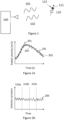
- Figure 1 shows a radar transceiver 100 monitoring the path of a projectile 110 by way of an emitted radar signal 101 and a reflected radar signal 102.
- the radar generates a series of observations of the path of the projectile, comprising information about the radial velocity of the projectile relative to the radar transceiver.
- the projectile 110 rotates about an axis 111 with a frequency of rotation, or spin rate, 112.
- spin is a spin rate, typically measured in terms of the number of full revolutions of the projectile around its rotational axis per unit time, e.g. in revolutions per minute (RPM) or revolutions per second (RPS).
- Figure 2a shows a first time series 201 of observations of the radial velocity, given, e.g., in m/s, together with the center radial velocity 202.
- the observations of radial velocity exhibit a variation around the center radial velocity.
- the center radial velocity may be seen as an average radial velocity of the projectile with respect to the radar transceiver, while the observations of radial velocity vary around this center velocity.
- Figure 2b schematically shows the difference between the observed radial velocity and the center velocity over time, i.e. it shows a second time series 203 comprising the variation in the radial velocity around the center radial velocity.
- the method for estimating a spin of a projectile 110 disclosed here and shown in Figure 5 comprises obtaining S1 from a radar transceiver 100 a first time series 201 comprising observations of a radial velocity of the projectile 110 relative to the radar transceiver 100, and calculating S2, from the first time series 201, a center velocity 202 of the projectile 110.
- the method further comprises extracting S3 a second time series 203 comprising a variation in the first time series around the center velocity 202, estimating S4 a frequency of the second time series 203, and determining S5 the spin of the projectile 110 based on the frequency of the second time series 203.
- the projectile 110 may be a sports ball, such as a baseball, soccer ball, or golf ball.
- the connection between the frequency of the second time series 203 and the spin of the projectile 110 is, in general, that the frequency of the second times series 203 is also the frequency of rotation and thus equivalent to the spin rate. It should however be noted that the frequency of the second time series 203 may also be e.g. a higher harmonic of the frequency of rotation. Harmonics, or integer multiples, of the frequency of rotation will be present in the second time series 203, and both the frequency of rotation and each higher harmonic will be associated with a signal strength. The strength of the harmonics relative to that of the frequency of rotation may depend on such things as whether more than one part of the projectile is causing reflection of the radar signal. Note that the signal strength for a harmonic may be zero.
- the projectile may also experience a temporary deformation during part of its trajectory, as can be the case for a sports ball such as a golf ball that is hit by an implement such as a golf club.
- the impact can cause a temporary compression of the sports ball, which then results in a gradually declining temporary deformation of the sports ball during flight.
- This deformation then impacts the reflection of the radar signal and may introduce a second periodic variation with a frequency that is not directly related to the spin rate.
- the method may also comprise dividing S31 the second time series 203 into a plurality of time intervals 210a, 210b, 210c, estimating S41 a plurality of frequencies of the second time series 203, where each frequency corresponds to a respective time interval in the plurality of time intervals 210a, 210b, 210c, and determining S51 the spin of the projectile 110 based on the plurality of estimated frequencies.
- a length of a time interval may be the time in which the projectile will cover a set distance, where the time is calculated using a known center velocity of the projectile.
- the set distance may for example be 30-40 m.
- the length of the time interval may also be set such that a desired signal-to-noise ratio and resolution is obtained for the estimated frequency.
- the length of a time interval may be between 250 and 500 milliseconds.
- Dividing the second time series 203 into a plurality of time intervals makes it possible to obtain a plurality of initial estimated frequencies.
- the estimated value of the frequency of the second time series 203 can be affected by measurement noise or measurement errors, rendering a single estimated frequency of the second time series 203 potentially unreliable.
- With a plurality of estimated frequencies it is possible to apply statistical methods to obtain a final estimate of the frequency that is more reliable than an estimate derived from a single time interval.
- Determining S51 the spin of the projectile 110 based on the plurality of estimated frequencies may also comprise obtaining a distribution 300 of the plurality of estimated frequencies. From a distribution of a plurality of estimated frequencies it is possible to extract a final estimate of the frequency.
- the final estimate of the frequency can be extracted through calculating a probability density function 310 for the plurality of estimated frequencies, optionally as a convolution of a histogram of the plurality of estimated frequencies with a kernel, optionally a Gaussian kernel. Subsequently the frequency corresponding to one of the resulting local maxima 311 in the probability density function 310 is identified as the final estimate of the frequency. Selection of the correct local maximum 311 can for example be performed on the basis of a probability mass associated with each local maximum. The probability mass corresponds to the integral of the probability density function in an interval 312 comprising the local maximum. The interval may be limited by the points closest to the local maximum at which the probability density function falls below a fixed threshold value or below a value corresponding to a percentage of the height of the local maximum.
- Selection of the correct local maximum 311 can also be performed on the basis of how many of the estimated frequencies in the plurality of estimated frequencies are equal or close to the frequency corresponding to the local maximum, optionally taking into account the number of estimates of the frequencies associated with other local maxima that correspond to harmonics of the frequency corresponding to the local maximum.
- the time interval between observations in the first time series 201 may be set to half the expected period of rotation of the projectile 110 at a highest expected spin. The time interval can also be less than half the expected period of rotation.
- the time interval between observations in the first time series 201 may be constant. As another example, the time interval between observations in the first time series 201 may be variable.
- the calculation S2 of a center velocity 202 of the projectile 110 from the first time series 201 may as an example be performed though use of a low-pass filter.
- a cut-off frequency for the low-pass filter may then be configured in dependence of an expected variation in velocity along the projectile trajectory.
- the center velocity 202 may be calculated through piecewise fitting of a function to the first time series 201.
- Extraction S3 of the second time series 203 may then be performed through subtraction of the determined center velocity 202 from the first time series 201.
- Estimating S4 the frequency of the second time series 203 may comprise using a power spectrum 400 calculated from the second time series 203 as a basis for a maximum likelihood estimation of the frequency.
- the power spectrum can for example be found as the square of the absolute value of the Fourier transform of the second time series 203.
- another representation of the power density of the signal at different frequencies can be used, such as a periodogram.
- a maximum likelihood estimation of the frequency may for example be obtained as follows.
- a plurality of candidate frequencies may be obtained, for example based on the frequencies at which the power spectrum 400 has local maxima 401.
- the height of the corresponding peak and peaks at integer multiples of the candidate frequency i.e. harmonics
- the candidate frequency with the highest measure of total power is then selected as the estimated frequency of the second time series 203.
- Maximum likelihood estimation of a frequency, in particular a fundamental frequency is well known in the art.
- the frequency may be a fundamental frequency.
- the fundamental frequency is herein defined as in the field of harmonic analysis, i.e. as the lowest frequency present in a periodic signal, the signal in this case being the second time series 203.
- a radar transceiver 100 arranged to obtain S1 a first time series 201 comprising observations of a radial velocity of the projectile 110 relative to the radar transceiver 100, calculate S2, from the first time series 201, a center velocity 202 of the projectile 110, extract S3 a second time series 203 comprising a variation in the first time series 201 around the center velocity 202, estimate S4 a frequency of the second time series 203, and determine S5 the spin of the projectile 110 based on the estimated frequency of the second time series 203.
- the radar transceiver may also be arranged to divide S31 the second time series 203 into a plurality of time intervals, estimate S41 a plurality of frequencies of the second time series 203, where each frequency corresponds to a respective time interval in the plurality of time intervals, and determine S51 the spin of the projectile 110 based on the plurality of estimated frequencies.
- the radar transceiver described above may, as an example, be a frequency modulated continuous wave, FMCW, radar transceiver.
- the radar transceiver may be a pulse-Doppler radar.
- the radar transceiver may be arranged to measure other properties of the projectile trajectory, such as velocity and position or the projectile 110 at different times.
- a means 601 of displaying the determined spin may be a display, such as a LED or LCD display.
- a means of displaying the determined spin may also be a computer running a computer program capable of displaying the determined spin.
- other properties of the projectile trajectory such as velocity and position of the projectile 110 at different times, may be displayed together with the determined spin.
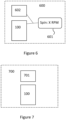
- the system 600 may also comprise an auxiliary sensor 602, wherein the spin estimate from the radar transceiver 100 is combined with data obtained from the auxiliary sensor 602.
- the auxiliary sensor may be a camera.
- the auxiliary sensor may be a LIDAR or sonar sensor.
- a processor 701 arranged to obtain S1 a first time series 201 comprising observations of a radial velocity of the projectile 110 relative to the radar transceiver 100, calculate S2, from the first time series 201, a center velocity 202 of the projectile 110, extract S3 a second time series 203 comprising a variation in the first time series 201 around the center velocity, estimate S4 a frequency of the second time series 203, and determine S5 the spin of the projectile 110 based on the frequency of the second time series 203.
- the processor 701 may also be arranged to divide S31 the second time series 203 into a plurality of time intervals, estimate S41 a plurality of frequencies of the second time series 203, where each frequency corresponds to a respective time interval in the plurality of time intervals, and determine S51 the spin of the projectile 110 based on the plurality of estimated frequencies.
- a system 700 comprising a radar transceiver 100 and a processor 701 as described above.
- a computer program for operating a radar transceiver 100 or processor 701 to determine the spin of a projectile 110 comprising computer code which, when run on processing circuitry of a radar transceiver 100 causes the radar transceiver 100 to execute a method as described above, and a computer program product comprising a computer program as described, and a computer readable storage medium on which the computer program is stored.
Landscapes
- Engineering & Computer Science (AREA)
- Radar, Positioning & Navigation (AREA)
- Remote Sensing (AREA)
- Physics & Mathematics (AREA)
- Computer Networks & Wireless Communication (AREA)
- General Physics & Mathematics (AREA)
- Health & Medical Sciences (AREA)
- General Health & Medical Sciences (AREA)
- Physical Education & Sports Medicine (AREA)
- Electromagnetism (AREA)
- Life Sciences & Earth Sciences (AREA)
- Biophysics (AREA)
- Radar Systems Or Details Thereof (AREA)
Description
- The present disclosure relates to the use of radar transceivers to determine the spin of a projectile.
- When monitoring the path of a projectile, it can be advantageous to be able to determine its rate of rotation, or spin, as it will affect the overall path of the projectile. This can for instance be of importance when monitoring the path of a sports ball such as a baseball or golf ball.
-
US8845442 discloses a method for determining the spin of a sports ball comprising calculating the spin from a modulation frequency of a reflected radar signal and harmonics of said modulation frequency. -
US9868044 - However, there is a need for more refined methods for determining the spin of a projectile.
-
US 2018/0136326 describes a radar system and method for determining a rotational state of a moving object. - The invention is defined by the appended claims.
- It is an object of the present disclosure to provide a method for determining the spin of a projectile. This object is obtained by a method according to claim 1.
- The variation in the first time series around the center velocity of the projectile is caused by reflections of the radar signal from features of the projectile, as said features rotate towards or away from the radar due to the spin. Thus, the frequency of the second time series depends on the spin rate, and the spin can easily be determined from the frequency.
- The method may also comprise dividing the second time series into a plurality of time intervals, estimating a plurality of frequencies of the second time series, where each frequency corresponds to a respective time interval in the plurality of time intervals, and determining the spin of the projectile based on the plurality of estimated frequencies.
- Advantageously, dividing the second time series into a plurality of time intervals may yield a more reliable final estimate of the spin. The estimated value of the frequency corresponding to a time interval can be affected by measurement noise or measurement errors, rendering it potentially unreliable. With a plurality of estimated frequencies, it is possible to apply statistical methods to obtain a final estimate of the spin that is more reliable than an estimate derived from a single estimated frequency.
- According to aspects, determining the spin of the projectile based on the plurality of estimated frequencies comprises obtaining a distribution of the plurality of estimated frequencies.
- According to other aspects, the method may comprise that a time interval between observations in the first time series is at most half an expected period of rotation of the projectile at a highest expected spin. This has the advantage that at least two observations of the radial velocity are obtained per rotation of the projectile, ensuring that the variation in the radial velocity due to spin is captured in the first time series.
- According to aspects, the time interval between observations in the first time series is constant. According to other aspects, the time interval between observations in the first time series is variable. The center velocity may be calculated through use of a low-pass filter or through piecewise fitting of a function to the first time series. Advantageously, both methods can yield reliable estimates of the center velocity.
- According to aspects, the second time series may be extracted through subtraction of the calculated center velocity from the first time series.
- According to aspects, estimating the frequency of the second time series may comprise using a power spectrum calculated from the second time series as a basis for a maximum likelihood estimation of the frequency. Advantageously, a power spectrum provides a measure of the power associated with each frequency present in the signal, which facilitates estimation of the frequency. According to aspects, the frequency may be a fundamental frequency of the signal. Advantageously, the fundamental frequency is generally equivalent to the spin rate.
- The object is also obtained by a radar transceiver according to claim 9.
- The radar transceiver may also be arranged to divide the second time series into a plurality of time intervals, estimate a plurality of frequencies of the second time series, where each frequency corresponds to a respective time interval in the plurality of time intervals, and determine the spin of the projectile based on the plurality of estimated of the frequencies.
- According to aspects, the radar transceiver may be a frequency modulated continuous wave, FMCW, radar transceiver.
- The object is further obtained by a system according to claim 11. Advantageously, incorporating a means of displaying the determined spin enables easier access to the determined spin for a person using the system
- According to aspects, the system may comprise an auxiliary sensor, and the spin estimate from the radar transceiver is combined with data obtained from the auxiliary sensor. Advantageously, combining the spin estimate with data obtained from an auxiliary sensor may facilitate evaluation of the projectile trajectory by a person using the system.
- The radar transceivers and systems disclosed herein are associated with the same advantages as discussed above in relation to the different methods.
- The object is also obtained by a computer readable storage medium according to claim 14 or by a computer product according to claim 15.
- Generally, all terms used in the claims are to be interpreted according to their ordinary meaning in the technical field, unless explicitly defined otherwise herein. All references to "a/an/the element, apparatus, component, means, step, etc." are to be interpreted openly as referring to at least one instance of the element, apparatus, component, means, step, etc., unless explicitly stated otherwise. Further features of, and advantages with, the present invention will become apparent when studying the appended claims and the following description.
- The present disclosure will now be described more in detail with reference to the appended drawings, where:
-
Figure 1 schematically illustrates observation of a projectile by a radar transceiver; -
Figure 2 schematically illustrates the change in radial velocity of a projectile over time; -
Figure 3 schematically illustrates a distribution of estimates of the spin of a projectile; -
Figure 4 schematically illustrates a power spectrum; -
Figure 5 is a flowchart illustrating methods in a radar transceiver according to the present disclosure; -
Figure 6 is a block diagram of a system comprising a radar transceiver; and -
Figure 7 is a block diagram of a system comprising a radar transceiver and a processor. - Aspects of the present disclosure will now be described more fully with reference to the accompanying drawings. Like numbers in the drawings refer to like elements throughout.
- As used herein, the singular forms "a", "an" and "the" are intended to include the plural forms as well, unless the context clearly indicates otherwise.
- Measurement of a projectile trajectory with a radar transceiver entails the radar transceiver emitting a radar signal, the radar signal being reflected at least in part by the projectile, and the transceiver receiving the reflected signal. From the modulation introduced into the signal through reflection against the projectile, trajectory parameters such as the position and velocity of the projectile can be extracted through methods well known in the art. Specifically, the radial velocity of the projectile relative to the radar transceiver can be obtained from a Doppler shift in the reflected signal.
- The strongest reflections of the radar signal frequently occur on asymmetric or uneven parts of the projectile. For an otherwise mostly spherically symmetric projectile such as e.g. a sports ball, reflections might occur in a place where two halves of the sports ball are joined, e.g., glued together. If the material of the projectile is at least partially transparent to radio waves, as is the case with many polymer-based materials, reflection can also occur from inhomogeneities in the material within the projectile. Occasionally, markings are added to sports balls to assist in observation and tracking with radar transceivers or other sensors, and these may also reflect radar signals. Some sports balls may also be configured to facilitate determination of spin using electromagnetic signals. For instance, an electrically conducting material may be arranged in the sports ball interior.
- As an example, consider a spherical projectile, e.g. a ball, moving away from the radar transceiver and simultaneously spinning around an axis of the ball. The largest contribution to the observed radial velocity will in this case be the center radial velocity of the projectile, i.e. the radial velocity that would be observed if the projectile were not spinning. This center radial velocity normally coincides with a radial velocity of the center of mass of the projectile relative to the radar transceiver. For a spinning projectile, however, the momentary observed radial velocity of the projectile relative to the radar transceiver will depend on the movement around the rotational axis of the part of the projectile causing the strongest reflection. When the part of the projectile causing the strongest reflection is rotating away from the transceiver, the momentary observed radial velocity will be higher than the center radial velocity. Conversely, when the part of the projectile causing strongest reflection is on the side rotating towards the transceiver, the momentary observed radial velocity will be lower than the center radial velocity. This periodic variation of the observed radial velocity around the center radial velocity can be used to extract the spin rate of the projectile. The spin rate can be determined in this way for most orientations of the rotational axis. The exception is a scenario where the rotational axis points towards the transceiver at every point in the projectile trajectory. However, such scenarios are very rare.
-
Figure 1 shows aradar transceiver 100 monitoring the path of a projectile 110 by way of an emittedradar signal 101 and a reflectedradar signal 102. The radar generates a series of observations of the path of the projectile, comprising information about the radial velocity of the projectile relative to the radar transceiver. The projectile 110 rotates about anaxis 111 with a frequency of rotation, or spin rate, 112. Herein, spin is a spin rate, typically measured in terms of the number of full revolutions of the projectile around its rotational axis per unit time, e.g. in revolutions per minute (RPM) or revolutions per second (RPS). -
Figure 2a shows afirst time series 201 of observations of the radial velocity, given, e.g., in m/s, together with the centerradial velocity 202. Note that the observations of radial velocity exhibit a variation around the center radial velocity. In fact, the center radial velocity may be seen as an average radial velocity of the projectile with respect to the radar transceiver, while the observations of radial velocity vary around this center velocity.Figure 2b schematically shows the difference between the observed radial velocity and the center velocity over time, i.e. it shows asecond time series 203 comprising the variation in the radial velocity around the center radial velocity. - The method for estimating a spin of a projectile 110 disclosed here and shown in
Figure 5 comprises obtaining S1 from a radar transceiver 100 afirst time series 201 comprising observations of a radial velocity of the projectile 110 relative to theradar transceiver 100, and calculating S2, from thefirst time series 201, acenter velocity 202 of the projectile 110. The method further comprises extracting S3 asecond time series 203 comprising a variation in the first time series around thecenter velocity 202, estimating S4 a frequency of thesecond time series 203, and determining S5 the spin of the projectile 110 based on the frequency of thesecond time series 203. The projectile 110 may be a sports ball, such as a baseball, soccer ball, or golf ball. - The connection between the frequency of the
second time series 203 and the spin of the projectile 110 is, in general, that the frequency of thesecond times series 203 is also the frequency of rotation and thus equivalent to the spin rate. It should however be noted that the frequency of thesecond time series 203 may also be e.g. a higher harmonic of the frequency of rotation. Harmonics, or integer multiples, of the frequency of rotation will be present in thesecond time series 203, and both the frequency of rotation and each higher harmonic will be associated with a signal strength. The strength of the harmonics relative to that of the frequency of rotation may depend on such things as whether more than one part of the projectile is causing reflection of the radar signal. Note that the signal strength for a harmonic may be zero. - Depending on how the projectile is launched it may also experience a temporary deformation during part of its trajectory, as can be the case for a sports ball such as a golf ball that is hit by an implement such as a golf club. The impact can cause a temporary compression of the sports ball, which then results in a gradually declining temporary deformation of the sports ball during flight. This deformation then impacts the reflection of the radar signal and may introduce a second periodic variation with a frequency that is not directly related to the spin rate.
- Optionally, the method may also comprise dividing S31 the
second time series 203 into a plurality oftime intervals second time series 203, where each frequency corresponds to a respective time interval in the plurality oftime intervals - Dividing the
second time series 203 into a plurality of time intervals makes it possible to obtain a plurality of initial estimated frequencies. The estimated value of the frequency of thesecond time series 203 can be affected by measurement noise or measurement errors, rendering a single estimated frequency of thesecond time series 203 potentially unreliable. With a plurality of estimated frequencies, it is possible to apply statistical methods to obtain a final estimate of the frequency that is more reliable than an estimate derived from a single time interval. - Determining S51 the spin of the projectile 110 based on the plurality of estimated frequencies may also comprise obtaining a
distribution 300 of the plurality of estimated frequencies. From a distribution of a plurality of estimated frequencies it is possible to extract a final estimate of the frequency. - As an example, the final estimate of the frequency can be extracted through calculating a
probability density function 310 for the plurality of estimated frequencies, optionally as a convolution of a histogram of the plurality of estimated frequencies with a kernel, optionally a Gaussian kernel. Subsequently the frequency corresponding to one of the resultinglocal maxima 311 in theprobability density function 310 is identified as the final estimate of the frequency. Selection of the correctlocal maximum 311 can for example be performed on the basis of a probability mass associated with each local maximum. The probability mass corresponds to the integral of the probability density function in aninterval 312 comprising the local maximum. The interval may be limited by the points closest to the local maximum at which the probability density function falls below a fixed threshold value or below a value corresponding to a percentage of the height of the local maximum. - Selection of the correct
local maximum 311 can also be performed on the basis of how many of the estimated frequencies in the plurality of estimated frequencies are equal or close to the frequency corresponding to the local maximum, optionally taking into account the number of estimates of the frequencies associated with other local maxima that correspond to harmonics of the frequency corresponding to the local maximum. - If the periodic variation in the observed radial velocity due to spin is to be detectable in the
first time series 201 and thesecond time series 203, a time interval between observations in thetime series 201 cannot exceed a period of rotation of the projectile due to the spin. If a highest expected value of the spin is known, the time interval between observations in thefirst time series 201 may be set to half the expected period of rotation of the projectile 110 at a highest expected spin. The time interval can also be less than half the expected period of rotation. - As an example, the time interval between observations in the
first time series 201 may be constant. As another example, the time interval between observations in thefirst time series 201 may be variable. - The calculation S2 of a
center velocity 202 of the projectile 110 from thefirst time series 201 may as an example be performed though use of a low-pass filter. A cut-off frequency for the low-pass filter may then be configured in dependence of an expected variation in velocity along the projectile trajectory. As another example, thecenter velocity 202 may be calculated through piecewise fitting of a function to thefirst time series 201. Extraction S3 of thesecond time series 203 may then be performed through subtraction of thedetermined center velocity 202 from thefirst time series 201. - Estimating S4 the frequency of the
second time series 203 may comprise using apower spectrum 400 calculated from thesecond time series 203 as a basis for a maximum likelihood estimation of the frequency. The power spectrum can for example be found as the square of the absolute value of the Fourier transform of thesecond time series 203. Optionally, another representation of the power density of the signal at different frequencies can be used, such as a periodogram. - A maximum likelihood estimation of the frequency may for example be obtained as follows. A plurality of candidate frequencies may be obtained, for example based on the frequencies at which the
power spectrum 400 haslocal maxima 401. For each candidate frequency, the height of the corresponding peak and peaks at integer multiples of the candidate frequency (i.e. harmonics) are added together to yield a measure of the total power in the signal associated with the candidate frequency. The candidate frequency with the highest measure of total power is then selected as the estimated frequency of thesecond time series 203. Maximum likelihood estimation of a frequency, in particular a fundamental frequency, is well known in the art. - Optionally, the frequency may be a fundamental frequency. The fundamental frequency is herein defined as in the field of harmonic analysis, i.e. as the lowest frequency present in a periodic signal, the signal in this case being the
second time series 203. - There is also herein disclosed a
radar transceiver 100 arranged to obtain S1 afirst time series 201 comprising observations of a radial velocity of the projectile 110 relative to theradar transceiver 100, calculate S2, from thefirst time series 201, acenter velocity 202 of the projectile 110, extract S3 asecond time series 203 comprising a variation in thefirst time series 201 around thecenter velocity 202, estimate S4 a frequency of thesecond time series 203, and determine S5 the spin of the projectile 110 based on the estimated frequency of thesecond time series 203. - The radar transceiver may also be arranged to divide S31 the
second time series 203 into a plurality of time intervals, estimate S41 a plurality of frequencies of thesecond time series 203, where each frequency corresponds to a respective time interval in the plurality of time intervals, and determine S51 the spin of the projectile 110 based on the plurality of estimated frequencies. - The radar transceiver described above may, as an example, be a frequency modulated continuous wave, FMCW, radar transceiver. As another example, the radar transceiver may be a pulse-Doppler radar. In addition to spin, the radar transceiver may be arranged to measure other properties of the projectile trajectory, such as velocity and position or the projectile 110 at different times.
- There is also herein disclosed a
system 600 for measurement of the spin of a projectile 110, the system comprising aradar transceiver 100 as described above and at least one means 601 of displaying the determined spin. A means 601 of displaying the determined spin may be a display, such as a LED or LCD display. A means of displaying the determined spin may also be a computer running a computer program capable of displaying the determined spin. Optionally, other properties of the projectile trajectory, such as velocity and position of the projectile 110 at different times, may be displayed together with the determined spin. - The
system 600 may also comprise anauxiliary sensor 602, wherein the spin estimate from theradar transceiver 100 is combined with data obtained from theauxiliary sensor 602. As an example, the auxiliary sensor may be a camera. As another example, the auxiliary sensor may be a LIDAR or sonar sensor. - There is also herein disclosed a
processor 701 arranged to obtain S1 afirst time series 201 comprising observations of a radial velocity of the projectile 110 relative to theradar transceiver 100, calculate S2, from thefirst time series 201, acenter velocity 202 of the projectile 110, extract S3 asecond time series 203 comprising a variation in thefirst time series 201 around the center velocity, estimate S4 a frequency of thesecond time series 203, and determine S5 the spin of the projectile 110 based on the frequency of thesecond time series 203. - The
processor 701 may also be arranged to divide S31 thesecond time series 203 into a plurality of time intervals, estimate S41 a plurality of frequencies of thesecond time series 203, where each frequency corresponds to a respective time interval in the plurality of time intervals, and determine S51 the spin of the projectile 110 based on the plurality of estimated frequencies. - There is also disclosed a
system 700 comprising aradar transceiver 100 and aprocessor 701 as described above. - Finally, there is herein disclosed a computer program for operating a
radar transceiver 100 orprocessor 701 to determine the spin of a projectile 110, the computer program comprising computer code which, when run on processing circuitry of aradar transceiver 100 causes theradar transceiver 100 to execute a method as described above, and a computer program product comprising a computer program as described, and a computer readable storage medium on which the computer program is stored.
Claims (15)
- A method for estimating a spin of a projectile (110), the method comprising:obtaining (S1) from a radar transceiver (100) a first time series (201) comprising observations of one or more trajectory parameters comprising a radial velocity of the projectile (110) relative to the radar transceiver (100);calculating (S2), from the first time series (201), a center radial velocity (202) of the projectile (110);extracting (S3) from the first time series (201) a second time series (203) comprising a variation of the radial velocity in the first time series (201) around the calculated center radial velocity (202);estimating (S4) a frequency of the second time series (203); anddetermining (S5) the spin of the projectile (110) based on the estimated frequency of the second time series (203).
- The method according to claim 1, wherein the method comprises:dividing (S31) the second time series (203) into a plurality of time intervals (210a, 210b, 210c);estimating (S41) a plurality of frequencies of the second time series (203), where each frequency corresponds to a respective time interval in the plurality of time intervals (210a, 210b, 210c); anddetermining (S51) the spin of the projectile (110) based on the plurality of estimated frequencies.
- The method according to claim 2, wherein determining (S51) the spin of the projectile (110) based on the plurality of estimated frequencies comprises obtaining a distribution (300) of the plurality of estimated frequencies.
- The method according to any previous claim, where a time interval between observations in the first time series (201) is at most half an expected period of rotation of the projectile (110) at a highest expected spin to ensure that a variation of the radial velocity is observed due to the spin of the projectile captured in the first time series (201).
- The method according to any previous claim, wherein the time interval between observations in the first time series (201) is constant, or wherein the time interval between observations in the first time series (201) is variable.
- The method according to any previous claim, wherein the center radial velocity (202) defines a radial velocity that would be observed if the projectile (110) were not spinning wherein the center radial velocity (202) is calculated (S2) through use of a low-pass filter, or wherein the center radial velocity (202) is calculated (S2) through piecewise fitting of a function to the first time series (201).
- The method according to any previous claim, wherein the second time series (203) is extracted (S3) through subtraction of the calculated center radial velocity (202) from the first time series (201).
- The method according to any previous claim, wherein estimating (S4) the frequency of the second time series (203) comprises using a power spectrum (400) calculated from the second time series (203) as a basis for a maximum likelihood estimation of the frequency,
wherein optionally the frequency is a fundamental frequency. - A radar transceiver (100) arranged to obtain (S1) a first time series (201) comprising observations of one or more trajectory parameters comprising a radial velocity of a projectile (110) relative to the radar transceiver (100); calculate (S2), from the first time series (201), a center radial velocity (202) of the projectile (110); extract (S3) a second time series (203) comprising a variation of the radial velocity in the first time series around the calculated center radial velocity (202); estimate (S4) a frequency of the second time series (203); and determine (S5) a spin of the projectile (110) based on the estimated frequency of the second time series (203).
- A radar transceiver (100) according to claim 9, further arranged to divide (S31) the second time series (203) into a plurality of time intervals; estimate (S41) a plurality of frequencies of the second time series (203), where each frequency corresponds to a respective time interval in the plurality of time intervals (210a, 210b, 210c); and determine (S51) the spin of the projectile (110) based on the plurality of estimated frequencies, where optionally the radar transceiver (100) is a frequency modulated continuous wave, FMCW, radar transceiver.
- A system (600) for measurement of a spin of a projectile (110), the system comprising a radar transceiver (100) according to any of claims 9 to 10 and at least one means (601) of displaying the determined spin.
- A system (600) according to claim 11, comprising an auxiliary sensor (602), wherein the spin determined by the radar transceiver (100) is combined with data obtained from the auxiliary sensor (602).
- A system (700) comprising a radar transceiver (100) according to any of claims 9 to 10 and a processor (701) arranged to execute a method according to any one of claims 1 to 8.
- A computer readable medium storing a computer program for operating a radar transceiver (100) according to any of the claims 9 to 10 to determine a spin of a projectile (110), the computer program comprising computer code which, when run on processing circuitry of the radar transceiver (100) causes the radar transceiver (100) to execute a method according to any one of claims 1-8.
- A computer product for operating a radar transceiver (100) or a processor to determine a spin of a projectile (110), the computer product comprising computer code, which when run on processing circuitry of the radar transceiver (100) or on the processor causes the processing circuitry or the processor to execute a method according to any one of claims 1 to 8.
Applications Claiming Priority (2)
| Application Number | Priority Date | Filing Date | Title |
|---|---|---|---|
| SE2030185A SE544234C2 (en) | 2020-06-03 | 2020-06-03 | Method for determing spin of a projectile |
| PCT/EP2021/064210 WO2021244943A1 (en) | 2020-06-03 | 2021-05-27 | Method for determining spin of a projectile |
Publications (3)
| Publication Number | Publication Date |
|---|---|
| EP4162288A1 EP4162288A1 (en) | 2023-04-12 |
| EP4162288B1 true EP4162288B1 (en) | 2024-10-23 |
| EP4162288C0 EP4162288C0 (en) | 2024-10-23 |
Family
ID=76250332
Family Applications (1)
| Application Number | Title | Priority Date | Filing Date |
|---|---|---|---|
| EP21729481.8A Active EP4162288B1 (en) | 2020-06-03 | 2021-05-27 | Method for determining spin of a projectile |
Country Status (9)
| Country | Link |
|---|---|
| US (3) | US11513208B2 (en) |
| EP (1) | EP4162288B1 (en) |
| JP (1) | JP7425896B2 (en) |
| KR (1) | KR20230022948A (en) |
| CN (1) | CN115867823A (en) |
| AU (1) | AU2021283650B2 (en) |
| ES (1) | ES2992215T3 (en) |
| SE (1) | SE544234C2 (en) |
| WO (1) | WO2021244943A1 (en) |
Families Citing this family (7)
| Publication number | Priority date | Publication date | Assignee | Title |
|---|---|---|---|---|
| SE544234C2 (en) * | 2020-06-03 | 2022-03-08 | Topgolf Sweden Ab | Method for determing spin of a projectile |
| US11779809B1 (en) | 2022-07-29 | 2023-10-10 | Topgolf International, Inc. | Method and system utilizing a golf shot API proxy |
| US20240115918A1 (en) * | 2022-10-06 | 2024-04-11 | Hitters Group, LLC. | Apparatus, methods, and systems for providing a baseball facility to allow a plurality of players to hit a baseball onto a single field |
| US12350563B1 (en) | 2023-11-22 | 2025-07-08 | Topgolf International, Inc. | Game with a fully scoreable outfield |
| US12246231B1 (en) | 2023-11-27 | 2025-03-11 | Topgolf International, Inc. | Reactive game play |
| EP4621757A1 (en) | 2024-03-22 | 2025-09-24 | Topgolf Sweden AB | Managing module and method for managing a captured trace of a golf ball |
| WO2026072405A1 (en) | 2024-09-25 | 2026-04-02 | Topgolf International, Inc. | Bandwidth reduction in a motion tracking apparatus |
Family Cites Families (36)
| Publication number | Priority date | Publication date | Assignee | Title |
|---|---|---|---|---|
| US5281971A (en) * | 1977-02-28 | 1994-01-25 | Ceridian Corporation | Radar techniques for detection of particular targets |
| US4728057A (en) * | 1985-11-22 | 1988-03-01 | Ship Systems, Inc. | Spin-stabilized projectile with pulse receiver and method of use |
| NL8600710A (en) * | 1986-03-20 | 1987-10-16 | Hollandse Signaalapparaten Bv | DEVICE FOR DETERMINING THE ROTATION POSITION OF AN OBJECT ROTATING ON AN AXIS. |
| US5246232A (en) * | 1992-01-22 | 1993-09-21 | Colorado Time Systems | Method and apparatus for determining parameters of the motion of an object |
| US6244971B1 (en) | 1999-01-28 | 2001-06-12 | The Distancecaddy Company, Llc | Spin determination for a rotating object |
| US20020107078A1 (en) * | 2000-12-11 | 2002-08-08 | Collins Robert J. | Detecting movement characteristics of an object |
| EP1698380B9 (en) * | 2005-03-03 | 2010-07-21 | Interactive Sports Games A/S | Determination of spin parameters of a sports ball |
| US10393870B2 (en) | 2005-03-03 | 2019-08-27 | Trackman A/S | Determination of spin parameters of a sports ball |
| US9645235B2 (en) | 2005-03-03 | 2017-05-09 | Trackman A/S | Determination of spin parameters of a sports ball |
| CA2740109C (en) | 2008-10-08 | 2016-01-19 | Interactive Sports Technologies Inc. | Sports simulation system |
| KR102033703B1 (en) | 2009-01-29 | 2019-10-17 | 트랙맨 에이/에스 | An assembly comprising a radar and an imaging element |
| JP5617481B2 (en) * | 2010-09-24 | 2014-11-05 | 横浜ゴム株式会社 | Ball measuring device |
| US9036864B2 (en) * | 2011-08-12 | 2015-05-19 | Edh Holdings (South Africa) (Pty) Ltd. | Ball trajectory and bounce position detection |
| WO2013172015A1 (en) * | 2012-05-16 | 2013-11-21 | 横浜ゴム株式会社 | Ball for ball game |
| KR101472274B1 (en) | 2013-01-08 | 2014-12-12 | (주) 골프존 | Device for sensing moving ball and method for the same |
| WO2014110398A1 (en) * | 2013-01-10 | 2014-07-17 | Edh Us Llc | Ball spin rate measurement |
| KR101810440B1 (en) * | 2013-11-13 | 2017-12-20 | 요코하마 고무 가부시키가이샤 | Moving body rotation speed measurement device |
| US10151831B2 (en) | 2013-12-03 | 2018-12-11 | Edh (Us) Llc | Golf ball spin axis measurement |
| US9911046B1 (en) * | 2014-11-13 | 2018-03-06 | The United States Of America, As Represented By The Secretary Of The Navy | Method and apparatus for computer vision analysis of spin rate of marked projectiles |
| US10605910B2 (en) * | 2015-01-06 | 2020-03-31 | Alphawave Golf (Pty) Ltd | Golf ball tracking system |
| KR101723432B1 (en) | 2015-06-12 | 2017-04-18 | 주식회사 골프존 | Device for sensing moving ball and method for the same |
| US9955126B2 (en) * | 2015-08-19 | 2018-04-24 | Rapsodo Pte. Ltd. | Systems and methods of analyzing moving objects |
| US10593048B2 (en) | 2016-01-07 | 2020-03-17 | Rapsodo Pte. Ltd. | Object surface matching with a template for flight parameter measurement |
| KR20180002408A (en) | 2016-06-29 | 2018-01-08 | 주식회사 크리에이츠 | Method, system and non-transitory computer-readable recording medium for measuring ball spin |
| KR101826837B1 (en) | 2016-08-12 | 2018-02-08 | 주식회사 골프존 | Device for calculating information on flight of ball, method for the same and recording medium recording the method readable by computing device |
| US10838057B2 (en) * | 2016-10-14 | 2020-11-17 | Lockheed Martin Corporation | Radar system and method for determining a rotational state of a moving object |
| ES2877049T3 (en) * | 2017-01-30 | 2021-11-16 | Topgolf Sweden Ab | System and procedure for tracking three-dimensional objects using a combination of radar and image data |
| KR101931592B1 (en) | 2017-12-12 | 2019-03-13 | 주식회사 골프존 | Device for sensing a moving ball and method for computing parameters of moving ball using the same |
| US10850179B2 (en) | 2018-03-13 | 2020-12-01 | Trackman A/S | System and method for determining a spin axis of a sports ball |
| US20200023235A1 (en) | 2018-07-17 | 2020-01-23 | Trackman A/S | System and method for optimizing a sports ball launch |
| EP3877061B1 (en) * | 2018-11-08 | 2026-02-18 | Full-Swing Golf, Inc. | Launch monitor |
| US10835803B2 (en) | 2019-03-18 | 2020-11-17 | Rapsodo Pte. Ltd. | Object trajectory simulation |
| US20200330830A1 (en) * | 2019-04-17 | 2020-10-22 | PFC Shared Services, LLC | Golf Ball Tracking System |
| US10935657B2 (en) * | 2019-05-07 | 2021-03-02 | Applied Concepts, Inc. | System and method for precision spin measurement using doppler radar |
| WO2021005577A1 (en) | 2019-07-11 | 2021-01-14 | Trackman A/S | System and method for determining spin measurements using ball marking |
| SE544234C2 (en) * | 2020-06-03 | 2022-03-08 | Topgolf Sweden Ab | Method for determing spin of a projectile |
-
2020
- 2020-06-03 SE SE2030185A patent/SE544234C2/en unknown
-
2021
- 2021-05-27 KR KR1020237000193A patent/KR20230022948A/en active Pending
- 2021-05-27 EP EP21729481.8A patent/EP4162288B1/en active Active
- 2021-05-27 ES ES21729481T patent/ES2992215T3/en active Active
- 2021-05-27 AU AU2021283650A patent/AU2021283650B2/en active Active
- 2021-05-27 CN CN202180039579.0A patent/CN115867823A/en active Pending
- 2021-05-27 US US17/613,678 patent/US11513208B2/en active Active
- 2021-05-27 WO PCT/EP2021/064210 patent/WO2021244943A1/en not_active Ceased
- 2021-05-27 JP JP2022573325A patent/JP7425896B2/en active Active
-
2022
- 2022-11-16 US US17/988,705 patent/US12105184B2/en active Active
-
2024
- 2024-09-05 US US18/825,793 patent/US20240427003A1/en active Pending
Also Published As
| Publication number | Publication date |
|---|---|
| US20220221572A1 (en) | 2022-07-14 |
| SE544234C2 (en) | 2022-03-08 |
| US20240427003A1 (en) | 2024-12-26 |
| SE2030185A1 (en) | 2021-12-04 |
| JP7425896B2 (en) | 2024-01-31 |
| WO2021244943A1 (en) | 2021-12-09 |
| JP2023528026A (en) | 2023-07-03 |
| AU2021283650B2 (en) | 2024-04-18 |
| KR20230022948A (en) | 2023-02-16 |
| US20230082660A1 (en) | 2023-03-16 |
| US11513208B2 (en) | 2022-11-29 |
| US12105184B2 (en) | 2024-10-01 |
| EP4162288C0 (en) | 2024-10-23 |
| ES2992215T3 (en) | 2024-12-10 |
| EP4162288A1 (en) | 2023-04-12 |
| CN115867823A (en) | 2023-03-28 |
| AU2021283650A1 (en) | 2022-12-15 |
Similar Documents
| Publication | Publication Date | Title |
|---|---|---|
| AU2021283650B2 (en) | Method for determining spin of a projectile | |
| US20240316402A1 (en) | System and method for determining a spin axis of a sports ball | |
| US11364428B2 (en) | Device for sensing a moving ball and method for computing parameters of moving ball using the same | |
| US11675045B2 (en) | Method and apparatus for adaptively filtering radar clutter | |
| US20100073218A1 (en) | Method and apparatus for radar surveillance and detection of sea targets | |
| JP5617480B2 (en) | Ball measuring device and ball measuring method | |
| FR2776779A1 (en) | METEOROLOGICAL RADAR SYSTEM | |
| EP1980873A2 (en) | History or image based methods for altitude determination in a radar altimeter | |
| JP2005521040A (en) | Target signature calculation and recognition system and method | |
| US9460242B2 (en) | Method for simulating run | |
| US6501418B1 (en) | Patrol speed acquisition in police Doppler radar | |
| EP1759224B1 (en) | Improvements relating to velocity extraction | |
| HK40091346A (en) | Method for determining spin of a projectile | |
| JP2725955B2 (en) | Method and apparatus for sensitivity speed control | |
| CN117452342A (en) | A chaff interference detection method based on polarization characteristics | |
| US12204047B2 (en) | Method and system for detecting the tumbling characteristics of space objects | |
| KR20160126394A (en) | Method and apparatus for measuring velocity using RADAR |
Legal Events
| Date | Code | Title | Description |
|---|---|---|---|
| STAA | Information on the status of an ep patent application or granted ep patent |
Free format text: STATUS: UNKNOWN |
|
| STAA | Information on the status of an ep patent application or granted ep patent |
Free format text: STATUS: THE INTERNATIONAL PUBLICATION HAS BEEN MADE |
|
| PUAI | Public reference made under article 153(3) epc to a published international application that has entered the european phase |
Free format text: ORIGINAL CODE: 0009012 |
|
| STAA | Information on the status of an ep patent application or granted ep patent |
Free format text: STATUS: REQUEST FOR EXAMINATION WAS MADE |
|
| 17P | Request for examination filed |
Effective date: 20221222 |
|
| AK | Designated contracting states |
Kind code of ref document: A1 Designated state(s): AL AT BE BG CH CY CZ DE DK EE ES FI FR GB GR HR HU IE IS IT LI LT LU LV MC MK MT NL NO PL PT RO RS SE SI SK SM TR |
|
| REG | Reference to a national code |
Ref country code: HK Ref legal event code: DE Ref document number: 40083540 Country of ref document: HK |
|
| DAV | Request for validation of the european patent (deleted) | ||
| DAX | Request for extension of the european patent (deleted) | ||
| GRAP | Despatch of communication of intention to grant a patent |
Free format text: ORIGINAL CODE: EPIDOSNIGR1 |
|
| STAA | Information on the status of an ep patent application or granted ep patent |
Free format text: STATUS: GRANT OF PATENT IS INTENDED |
|
| GRAJ | Information related to disapproval of communication of intention to grant by the applicant or resumption of examination proceedings by the epo deleted |
Free format text: ORIGINAL CODE: EPIDOSDIGR1 |
|
| STAA | Information on the status of an ep patent application or granted ep patent |
Free format text: STATUS: REQUEST FOR EXAMINATION WAS MADE |
|
| INTG | Intention to grant announced |
Effective date: 20240529 |
|
| GRAP | Despatch of communication of intention to grant a patent |
Free format text: ORIGINAL CODE: EPIDOSNIGR1 |
|
| STAA | Information on the status of an ep patent application or granted ep patent |
Free format text: STATUS: GRANT OF PATENT IS INTENDED |
|
| INTC | Intention to grant announced (deleted) | ||
| INTG | Intention to grant announced |
Effective date: 20240711 |
|
| GRAS | Grant fee paid |
Free format text: ORIGINAL CODE: EPIDOSNIGR3 |
|
| GRAA | (expected) grant |
Free format text: ORIGINAL CODE: 0009210 |
|
| STAA | Information on the status of an ep patent application or granted ep patent |
Free format text: STATUS: THE PATENT HAS BEEN GRANTED |
|
| AK | Designated contracting states |
Kind code of ref document: B1 Designated state(s): AL AT BE BG CH CY CZ DE DK EE ES FI FR GB GR HR HU IE IS IT LI LT LU LV MC MK MT NL NO PL PT RO RS SE SI SK SM TR |
|
| REG | Reference to a national code |
Ref country code: GB Ref legal event code: FG4D |
|
| REG | Reference to a national code |
Ref country code: CH Ref legal event code: EP |
|
| REG | Reference to a national code |
Ref country code: DE Ref legal event code: R096 Ref document number: 602021020657 Country of ref document: DE |
|
| REG | Reference to a national code |
Ref country code: IE Ref legal event code: FG4D |
|
| U01 | Request for unitary effect filed |
Effective date: 20241023 |
|
| U07 | Unitary effect registered |
Designated state(s): AT BE BG DE DK EE FI FR IT LT LU LV MT NL PT RO SE SI Effective date: 20241030 |
|
| REG | Reference to a national code |
Ref country code: ES Ref legal event code: FG2A Ref document number: 2992215 Country of ref document: ES Kind code of ref document: T3 Effective date: 20241210 |
|
| PG25 | Lapsed in a contracting state [announced via postgrant information from national office to epo] |
Ref country code: IS Free format text: LAPSE BECAUSE OF FAILURE TO SUBMIT A TRANSLATION OF THE DESCRIPTION OR TO PAY THE FEE WITHIN THE PRESCRIBED TIME-LIMIT Effective date: 20250223 Ref country code: HR Free format text: LAPSE BECAUSE OF FAILURE TO SUBMIT A TRANSLATION OF THE DESCRIPTION OR TO PAY THE FEE WITHIN THE PRESCRIBED TIME-LIMIT Effective date: 20241023 |
|
| PG25 | Lapsed in a contracting state [announced via postgrant information from national office to epo] |
Ref country code: NO Free format text: LAPSE BECAUSE OF FAILURE TO SUBMIT A TRANSLATION OF THE DESCRIPTION OR TO PAY THE FEE WITHIN THE PRESCRIBED TIME-LIMIT Effective date: 20250123 |
|
| PG25 | Lapsed in a contracting state [announced via postgrant information from national office to epo] |
Ref country code: GR Free format text: LAPSE BECAUSE OF FAILURE TO SUBMIT A TRANSLATION OF THE DESCRIPTION OR TO PAY THE FEE WITHIN THE PRESCRIBED TIME-LIMIT Effective date: 20250124 |
|
| PG25 | Lapsed in a contracting state [announced via postgrant information from national office to epo] |
Ref country code: PL Free format text: LAPSE BECAUSE OF FAILURE TO SUBMIT A TRANSLATION OF THE DESCRIPTION OR TO PAY THE FEE WITHIN THE PRESCRIBED TIME-LIMIT Effective date: 20241023 |
|
| PG25 | Lapsed in a contracting state [announced via postgrant information from national office to epo] |
Ref country code: RS Free format text: LAPSE BECAUSE OF FAILURE TO SUBMIT A TRANSLATION OF THE DESCRIPTION OR TO PAY THE FEE WITHIN THE PRESCRIBED TIME-LIMIT Effective date: 20250123 |
|
| U20 | Renewal fee for the european patent with unitary effect paid |
Year of fee payment: 5 Effective date: 20250423 |
|
| PG25 | Lapsed in a contracting state [announced via postgrant information from national office to epo] |
Ref country code: SM Free format text: LAPSE BECAUSE OF FAILURE TO SUBMIT A TRANSLATION OF THE DESCRIPTION OR TO PAY THE FEE WITHIN THE PRESCRIBED TIME-LIMIT Effective date: 20241023 |
|
| PGFP | Annual fee paid to national office [announced via postgrant information from national office to epo] |
Ref country code: GB Payment date: 20250423 Year of fee payment: 5 Ref country code: ES Payment date: 20250602 Year of fee payment: 5 |
|
| PG25 | Lapsed in a contracting state [announced via postgrant information from national office to epo] |
Ref country code: SK Free format text: LAPSE BECAUSE OF FAILURE TO SUBMIT A TRANSLATION OF THE DESCRIPTION OR TO PAY THE FEE WITHIN THE PRESCRIBED TIME-LIMIT Effective date: 20241023 |
|
| PG25 | Lapsed in a contracting state [announced via postgrant information from national office to epo] |
Ref country code: CZ Free format text: LAPSE BECAUSE OF FAILURE TO SUBMIT A TRANSLATION OF THE DESCRIPTION OR TO PAY THE FEE WITHIN THE PRESCRIBED TIME-LIMIT Effective date: 20241023 |
|
| PLBE | No opposition filed within time limit |
Free format text: ORIGINAL CODE: 0009261 |
|
| STAA | Information on the status of an ep patent application or granted ep patent |
Free format text: STATUS: NO OPPOSITION FILED WITHIN TIME LIMIT |
|
| 26N | No opposition filed |
Effective date: 20250724 |
|
| REG | Reference to a national code |
Ref country code: CH Ref legal event code: H13 Free format text: ST27 STATUS EVENT CODE: U-0-0-H10-H13 (AS PROVIDED BY THE NATIONAL OFFICE) Effective date: 20251223 |
|
| PG25 | Lapsed in a contracting state [announced via postgrant information from national office to epo] |
Ref country code: CH Free format text: LAPSE BECAUSE OF NON-PAYMENT OF DUE FEES Effective date: 20250531 |
|
| PG25 | Lapsed in a contracting state [announced via postgrant information from national office to epo] |
Ref country code: MC Free format text: LAPSE BECAUSE OF FAILURE TO SUBMIT A TRANSLATION OF THE DESCRIPTION OR TO PAY THE FEE WITHIN THE PRESCRIBED TIME-LIMIT Effective date: 20241023 |
|
| PG25 | Lapsed in a contracting state [announced via postgrant information from national office to epo] |
Ref country code: IE Free format text: LAPSE BECAUSE OF NON-PAYMENT OF DUE FEES Effective date: 20250527 |
|
| U1N | Appointed representative for the unitary patent procedure changed after the registration of the unitary effect |
Representative=s name: NORENS PATENTBYRA AB; SE |