EP4162154B1 - Clamp system and filter arrangement and methods - Google Patents
Clamp system and filter arrangement and methods Download PDFInfo
- Publication number
- EP4162154B1 EP4162154B1 EP21735825.8A EP21735825A EP4162154B1 EP 4162154 B1 EP4162154 B1 EP 4162154B1 EP 21735825 A EP21735825 A EP 21735825A EP 4162154 B1 EP4162154 B1 EP 4162154B1
- Authority
- EP
- European Patent Office
- Prior art keywords
- clamp
- filter
- support member
- filter element
- support
- Prior art date
- Legal status (The legal status is an assumption and is not a legal conclusion. Google has not performed a legal analysis and makes no representation as to the accuracy of the status listed.)
- Active
Links
Images













Classifications
-
- B—PERFORMING OPERATIONS; TRANSPORTING
- B01—PHYSICAL OR CHEMICAL PROCESSES OR APPARATUS IN GENERAL
- B01D—SEPARATION
- B01D46/00—Filters or filtering processes specially modified for separating dispersed particles from gases or vapours
- B01D46/0002—Casings; Housings; Frame constructions
- B01D46/0005—Mounting of filtering elements within casings, housings or frames
-
- B—PERFORMING OPERATIONS; TRANSPORTING
- B01—PHYSICAL OR CHEMICAL PROCESSES OR APPARATUS IN GENERAL
- B01D—SEPARATION
- B01D46/00—Filters or filtering processes specially modified for separating dispersed particles from gases or vapours
- B01D46/02—Particle separators, e.g. dust precipitators, having hollow filters made of flexible material
- B01D46/023—Pockets filters, i.e. multiple bag filters mounted on a common frame
-
- B—PERFORMING OPERATIONS; TRANSPORTING
- B01—PHYSICAL OR CHEMICAL PROCESSES OR APPARATUS IN GENERAL
- B01D—SEPARATION
- B01D46/00—Filters or filtering processes specially modified for separating dispersed particles from gases or vapours
- B01D46/10—Particle separators, e.g. dust precipitators, using filter plates, sheets or pads having plane surfaces
- B01D46/12—Particle separators, e.g. dust precipitators, using filter plates, sheets or pads having plane surfaces in multiple arrangements
- B01D46/121—V-type arrangements
-
- B—PERFORMING OPERATIONS; TRANSPORTING
- B01—PHYSICAL OR CHEMICAL PROCESSES OR APPARATUS IN GENERAL
- B01D—SEPARATION
- B01D46/00—Filters or filtering processes specially modified for separating dispersed particles from gases or vapours
- B01D46/42—Auxiliary equipment or operation thereof
- B01D46/4227—Manipulating filters or filter elements, e.g. handles or extracting tools
-
- B—PERFORMING OPERATIONS; TRANSPORTING
- B01—PHYSICAL OR CHEMICAL PROCESSES OR APPARATUS IN GENERAL
- B01D—SEPARATION
- B01D2265/00—Casings, housings or mounting for filters specially adapted for separating dispersed particles from gases or vapours
- B01D2265/02—Non-permanent measures for connecting different parts of the filter
- B01D2265/027—Quick closing means for, e.g. filter heads, caps, maintenance openings
-
- B—PERFORMING OPERATIONS; TRANSPORTING
- B01—PHYSICAL OR CHEMICAL PROCESSES OR APPARATUS IN GENERAL
- B01D—SEPARATION
- B01D2271/00—Sealings for filters specially adapted for separating dispersed particles from gases or vapours
- B01D2271/02—Gaskets, sealings
-
- B—PERFORMING OPERATIONS; TRANSPORTING
- B01—PHYSICAL OR CHEMICAL PROCESSES OR APPARATUS IN GENERAL
- B01D—SEPARATION
- B01D2279/00—Filters adapted for separating dispersed particles from gases or vapours specially modified for specific uses
- B01D2279/60—Filters adapted for separating dispersed particles from gases or vapours specially modified for specific uses for the intake of internal combustion engines or turbines
-
- B—PERFORMING OPERATIONS; TRANSPORTING
- B01—PHYSICAL OR CHEMICAL PROCESSES OR APPARATUS IN GENERAL
- B01D—SEPARATION
- B01D46/00—Filters or filtering processes specially modified for separating dispersed particles from gases or vapours
- B01D46/52—Particle separators, e.g. dust precipitators, using filters embodying folded corrugated or wound sheet material
- B01D46/521—Particle separators, e.g. dust precipitators, using filters embodying folded corrugated or wound sheet material using folded, pleated material
-
- F—MECHANICAL ENGINEERING; LIGHTING; HEATING; WEAPONS; BLASTING
- F02—COMBUSTION ENGINES; HOT-GAS OR COMBUSTION-PRODUCT ENGINE PLANTS
- F02C—GAS-TURBINE PLANTS; AIR INTAKES FOR JET-PROPULSION PLANTS; CONTROLLING FUEL SUPPLY IN AIR-BREATHING JET-PROPULSION PLANTS
- F02C7/00—Features, components parts, details or accessories, not provided for in, or of interest apart form groups F02C1/00 - F02C6/00; Air intakes for jet-propulsion plants
- F02C7/04—Air intakes for gas-turbine plants or jet-propulsion plants
- F02C7/05—Air intakes for gas-turbine plants or jet-propulsion plants having provisions for obviating the penetration of damaging objects or particles
- F02C7/055—Air intakes for gas-turbine plants or jet-propulsion plants having provisions for obviating the penetration of damaging objects or particles with intake grids, screens or guards
Definitions
- This disclosure relates to air filter systems. In certain applications, it concerns air filters for use in air intake of gas turbine systems and a clamp arrangement. Methods are also provided.
- Gas turbine systems are useful in generating electricity. These types of systems are convenient in that they can be constructed quickly and they produce fewer harmful emissions than coal or oil. Gas turbines utilize air for combustion purposes. The combustion air needs to be clean. To ensure clean air for combustion, air filters have been used to clean the air taken into the gas turbine system.
- Filters are used to purify the air intake for gas turbines.
- An example gas turbine air intake system is disclosed in U.S. 8,673,040 .
- Another example is disclosed in US 2014/096493 .
- the air filters used in these intake systems need to be periodically removed and replaced. It is desirable to find a convenient system for allowing for the quick and easy servicing of these air filters. In particular, it is desirable to have a system in which a single clamp system can be used for both the first filter and second filter, and allow the second filter to remain sealed in placed while the first filter is being serviced.
- This disclosure provides a solution to the problem in the prior art in the form of a clamp system according to claim 1, a filter system according to claim 8 and a method of servicing a filter arrangement according to claim 15.
- the solution provided herein allows for a single clamp that seals both a first filter and second filter to the support grid of an intake air system of a gas turbine and also allows for keeping the second filter in sealing engagement with the support grid while releasing the first filter for replacement.
- the clamp can also selectively release the second element for periodic removal and replacement.
- a clamp system for releasably attaching a filter assembly to a support grid
- the clamp system includes: (a) an elongated support member with first and second opposite open ends, a first slide channel adjacent the first end; and a second slide channel adjacent the second end; (b) a first clamp slidably mounted in the first open end; (c) a second clamp slidably mounted in the second open end; (d) a first slide pin arrangement slidably mounted in the first slide channel between a locked and a released position; (e) a second slide pin arrangement slidably mounted in the second slide channel between a locked and a released position; (f) an elongated omega clamp removably mounted to cover the support member; the omega clamp having first and second spaced through slots; (i) the first through slot slidably accommodating a portion of the first slide pin arrangement; (ii) the second through slot slidably accommodating a portion of the second slide pin arrangement; (
- the clamp system can further include a separate maintenance tool constructed and arranged to engage each of the first and second pivot rods and apply an axial force against the omega clamp.
- the maintenance tool can include (a) a head defining a recess sized to engage the first and second pivot rods, and a cam surface on a portion of the head opposite of the recess; and (b) a grasping handle extending from the head.
- Each of the first and second pivot rods includes a barrel nut on a portion of the pivot rods opposite of the hinge point.
- Each of the first clamp and second clamp includes: (a) a slide rod sized to be slidably received within one of the first and second open ends of the support member; (b) a post secured to and perpendicular to the slide rod; and (c) a flange secured to a distal portion of the post and parallel to and facing the slide rod to form a gasket holding recess therebetween.
- Each of the first and second slide pin arrangements includes: (a) a pin slide rod sized to slide within one of the first and second slide channels; (b) a support secured to and perpendicular to the pin slide rod; (c) a pin flange secured to a distal portion of the support and parallel to the pin slide rod with an interior side facing the pin slide rod and an opposite exterior side; and (d) pin projecting from the exterior side and sized to slide within one of the first and second slots in the omega clamp.
- the omega clamp comprises: (a) a base with a pair of legs extending perpendicular to the base; (i) the base defining the first and second through slots; (ii) the base having an exterior side and an opposite interior side; (b) each of the legs being bent at a non-zero angle remote from the base and away from each other; the legs and the interior side of the base defining an open channel; and (c) first and second pin slider keepers secured to the interior side of the base and overlapping a portion of the first and second through slots.
- the omega clamp comprises: (a) a base with a pair of legs extending perpendicular to the base; (i) the base defining the first and second through slots; (ii) the base having an exterior side and an opposite interior side; (b) each of the legs being bent at a non-zero angle remote from the base and away from each other; the legs and the interior side of the base defining an open channel; and (c) first and second pin slider keepers secured to the interior side of the base and overlapping a portion of the first and second through slots; (i) the first and second pin slider keepers being sized to slidably receive one of the pin flanges to put the first and second slide pin arrangements in the locked positions; and wherein when the first and second slide pin arrangements are slid to the released position, each of the pin flanges are slid to be free of the first and second pin slider keepers, and the omega clamp is free to be pivoted with the first and second pivot rods along the pivot axis away from covering the support member.
- a clamp system for releasably attaching a filter assembly to a support grid comprising: (a) a support member; (b) first and second clamps slidably mounted at opposite ends of the support member; (c) a first and second slide pin arrangements slidably mounted a portion of the support member; (d) an omega clamp removably mounted to cover the support member and slidably accommodating a portion of the first and second slide pin arrangement; (e) first and second pivot rods extending through and connecting the omega clamp and the support member; the first and second pivot rods each having a hinge point in the support member and a pivot axis along a length of the support member between opposite ends of the support member; and wherein, when the first and second slide pin arrangements are slid to a released position, the omega clamp is free to be pivoted with the first and second pivot rods along the pivot axis away from covering the support member.
- a filter system comprising: (a) a support grid having a frame with opposite first and second sides; (b) a first filter element oriented along the first side of the support grid; (c) a second filter oriented on the support grid directly across and opposing the first filter; and (d) a single clamp system releasably securing both the first filter element and the second filter element to the frame.
- the clamp system comprises: (a) a support member; (b) first and second clamps slidably mounted at opposite ends of the support member; (c) a first and second slide pin arrangements slidably mounted a portion of the support member; (d) an omega clamp removably mounted to cover the support member and slidably accommodating a portion of the first and second slide pin arrangement; (e) first and second pivot rods extending through and connecting the omega clamp and the support member; the first and second pivot rods each having a hinge point in the support member and a pivot axis along a length of the support member between opposite ends of the support member; and wherein, when the first and second slide pin arrangements are slid to a released position, the omega clamp is free to be pivoted with the first and second pivot rods along the pivot axis away from covering the support member.
- the clamp system includes: (a) an elongated support member with first and second opposite open ends, a first slide channel adjacent the first end; and a second slide channel adjacent the second end; (b) a first clamp slidably mounted in the first open end; (c) a second clamp slidably mounted in the second open end; (d) a first slide pin arrangement slidably mounted in the first slide channel between a locked and a released position; (e) a second slide pin arrangement slidably mounted in the second slide channel between a locked and a released position; (f) an elongated omega clamp removably mounted to cover the support member; the omega clamp having first and second spaced through slots; (i) the first through slot slidably accommodating a portion of the first slide pin arrangement; (ii) the second through slot slidably accommodating a portion of the second slide pin arrangement; (g) first and second pivot rods extending through and connecting the omega clamp and the support member; the first and second pivot rods each having a hinge point in the support
- the filter system can include (a) the first filter includes a perimeter frame with a gasket thereon; (b) the second filter includes a perimeter frame with a gasket thereon; and (c) a seal is formed with the first filter perimeter gasket being between and against the first and second clamps and the perimeter frame of the second filter.
- a seal is formed with the second filter perimeter gasket being between and against the omega clamp and the support grid frame.
- the first filter comprises a pocket filter
- the second filter comprises a pocket filter
- a method of servicing a filter arrangement in a gas turbine air inlet system comprising: (a) releasing a single clamp holding both of the first filter element and second filter element in place in sealing engagement on the support grid; (b) while the second filter element remains in sealing engagement on the support grid, removing the first filter element; and (c) providing a replacement first filter element and engaging the single clamp to seal the replacement first filter element to the support grid.
- the method can further comprise: (a) before the step of providing a replacement first filter element, releasing another part of the single clamp to remove the second filter element; and (b) providing a replacement second filter element and engaging the single clamp to seal the replacement second filter element to the support grid.
- the method can further include using the single clamp as variously characterized above.
- a clamp system for releasably attaching a filter assembly to a support grid
- the clamp system comprising a plurality of clamp rods; a first elongated support member with openings, each opening being sized to fit over one of the clamp rods; a first slide plate slidably mounted in the first support member; the first slide plate having openings alignable with the openings in the first support member; the first slide plate having an end handle; a second elongated support member with openings, each opening in the second support member sized to fit over one of the clamp rods; and a plurality of handgrips, each handgrip constructed and arranged to engage one of the clamp rods and apply an axial force against the second support member.
- the clamp system can further include a second slide plate slidably mounted in the second support member; the second slide plate having openings alignable with the openings in the second support member; and the second slide plate having an end handle.
- the handgrips each comprises: a head defining a recess sized to engage one of the clamp rods, and a cam surface on a portion of the head opposite of the recess; and a grasping handle extending from the head.
- the first support member may have a rectangular cross-sectional wall with opposite open ends, and the openings in the first support member extend through opposing sides of the wall; and the second support member may have a rectangular cross-sectional wall with opposite open ends, and the openings in the second support member extend through opposing sides of the wall of the second support member.
- the first slide plate openings have a narrowed region and a wider region.
- the second slide plate openings have a narrowed region and a wider region.
- a filter system using a clamp system comprising: a support grid having a frame with opposite upstream and downstream sides; a first filter element oriented along the upstream side of the support grid; a second filter element oriented on the support grid on the downstream side directly across and opposing the first filter element; and a single clamp system releasably securing both the first filter element and the second filter element to the frame.
- the second filter element may have a second element gasket pressed against the upstream side of the support grid; and the first filter element may have a first element gasket pressed against the clamp system.
- the clamp system comprises: one or more clamp rods extending from the support grid; a first elongated support member holding a first slide plate and positioned over the clamp rods; the first support member being positioned against the second element gasket; a second elongated support member positioned over the clamp rods and against the first element gasket, such that the first element gasket is positioned between and against the first support member and second support member; and one or more handgrips removably secured to the clamp rods and applying an axial force against the second support member.
- Further embodiments may comprise a second slide plate being held by the second support member and positioned over the clamp rods.
- first filter elements there are a plurality of first filter elements on the upstream side of the support grid; and the first filter elements comprise pocket filter elements or V-bank elements.
- the second filter elements there are a plurality of second filter elements on the downstream side of the support grid; and the second filter elements comprise V-bank filter elements.
- a method of servicing a filter arrangement in a gas turbine air inlet system having a support grid having a frame with opposite upstream and downstream sides; a first filter element releasably sealed to the upstream side of the support grid; and a second filter element releasably sealed to the upstream side of the support grid directly across and opposing the first filter element; the method comprising: releasing a single clamp assembly holding both of the first filter element and second filter element in place in sealing engagement on the support grid; while the second filter element remains in sealing engagement on the support grid, removing the first filter element; and providing a replacement first filter element and engaging the single clamp assembly to seal the replacement first filter element to the support grid.
- the method may further comprise, before the step of providing a replacement first filter element, releasing another part of the single clamp assembly to remove the second filter element; and providing a replacement second filter element and engaging the single clamp assembly to seal the replacement second filter element to the support grid.
- the step of engaging the single clamp assembly to seal the replacement first filter element to the support grid includes grasping a handgrip and rotating the handgrip from an open position to a closed position to apply an axial force against the clamp assembly.
- the step of engaging the single clamp assembly can include, after rotating the handgrip to apply an axial force against the clamp assembly, moving a first slide plate to lock the second filter element into a sealed position against the support grid.
- the method can further include, after the step of moving a first slide plate to lock the second filter element into a sealed position against the support grid, moving a second slide pate to lock the first filter element into a sealed position; and rotating the handgrip back to the open position and removing the handgrip.
- the method can include the single clamp assembly as variously characterized above.
- FIG. 1 shows a portion of a gas turbine air inlet system having a first filter element 20 and a second filter element 22.
- FIG. 1 also shows a portion of a first filter element 20 both vertically above and below the first element 20 shown in its entirety.
- the second filter element 22 also shows a portion of another second element 22 both vertically above and vertically below it.
- FIG. 1 a portion of a support grid 24 having a frame 26 is shown.
- the support grid 24 will include a matrix of several, for example hundreds, of rectangular grids with openings 28. Each opening 28 accommodates one of the second filters 22 and one of the first filters 20.
- the support grid 26 has opposite first and second sides 29, 30.
- the first side 29 is generally an upstream side, while the side 30 is a downstream side.
- the first filter element 20 and the second filter element 22 will be oriented on the support grid 24 in opposition to each other, such that the first filter element 20 is on the upstream side 24, while the second filter element 22 is on the downstream side 30.
- FIG. 1 Also visible in FIG. 1 is a clamp system 32.
- the clamp system 32 is shown at an upper portion of FIG. 1 as being exploded from the support grid 24, while the clamp system 32 at a lower portion of the FIG. is shown secured to the support grid 24.
- the clamp system 32 is a single clamp system that releasably secures the both the first filter element 20 and the second filter element 22 to the frame 26 of the support grid 24.
- the first filter element 20 includes a perimeter frame 34 all along each side of the first element 20.
- the perimeter frame includes a first side 34a ( FIG. 7 ) facing away from the filter media 21 and an opposite second side 34b facing toward the filter media 21.
- a gasket 36 ( FIGS. 7 and 8 ).
- Gasket 36 is secured to the frame 34 on the first side 34a facing away from the filter media 21 and is along the entire perimeter of the first element 20.
- the gasket 36 can be made from a variety of materials, including a soft foam.
- the second element 22 includes a perimeter frame 38 as can be seen in FIG. 1 the perimeter frame 38 is along the entire perimeter of the second element 22.
- the perimeter frame 38 includes a first side 38a facing away from the filter media 23, and an opposite second side 38b ( FIG. 7 ) facing toward the filter media 23.
- Secured to the perimeter frame 38 of the second element 22 is a gasket 40.
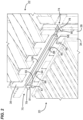
- the gasket 40 is not on the side 38a that is visible in FIG. 1 but can be seen in the cross-section in FIG. 7 at 38b.
- the gasket 40 is on a portion of the frame 38 that faces a remaining part of the second element 22.
- the gasket 40 for the second filter element 22 is compressed against the first or upstream side 29 of the frame 26 of the support grid 24.
- the gasket 36 of the first filter element 20 is then pressed against the frame 38 (first side 38a of the frame 38) of the second element 22.
- the clamp 32 holds the first filter element 20 and second filter element 22 in place in sealing engagement against the support grid 24.
- air to be filtered enters the first filter element 20, in which particulate and debris are removed by passing through the filter media 21.
- the filtered air then flows through the second element 22 by flowing from inside of the second element 22 through the media 23 to the outside on the downstream side, and then proceeds to the gas turbine.
- the first filter element 20 is located generally on an upstream side of the support grid 24, while the second element 22 is primarily located on the downstream side of the support grid 24, although the seal made with the gasket 40 of the second element 22 is along the first or upstream side 29 of the support grid 24.
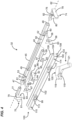
- an example clamp system 32 is illustrated in an exploded view.
- the clamp system 32 is used for releasably attaching the filter assembly, comprising the first element 20 and the second element 22 to the support grid 24.
- the clamp system 32 allows for using the single system 32 to hold both the first filter element 20 and the second filter element 22 in place in sealing engagement on the support grid 24. While the second filter element 22 remains in sealing engagement on the support grid 24, the clamp system 32 can be released to allow for removal and replacement of the first filter element 20.
- the clamp system 32 also allows for periodic removal and replacement of second element 22. Typically, the first filter elements 20 need removal and replacement at more frequent intervals than the second elements 22.
- the clamp system 32 includes an elongated support member or tube 45.
- the support tube 45 has first and second opposite open ends 46, 47.
- the support tube 45 also includes a first slide channel 48 adjacent to the first end 46, and a second slide channel 49 adjacent the second end 47.
- the first and second slide channels 48, 49 are formed by openings in the tube 45 spaced from the ends 46, 47.
- the tube 45 further includes a through hole 52 through the enclosure 50 and a remaining portion of the tube 45 and a through hole 53 through the enclosure 51 and a remaining portion of the tube 45.
- the through holes 52, 53 receive projections or pegs 55, 56 ( FIG. 1 ) extending from the frame 26 of the support grid 24. This allows for mounting of the tube 45 on and against the frame 26 of the grid 24.
- the clamp system 32 further includes first and second pivot rods 58, 59.
- the first and second pivot rods 58, 59 each has a swivel type hinge point 60, 61 held within the support tube 45 within a respective one of the enclosures 50, 51.
- the first and second pivot rods 58, 59 pivot along a pivot axis 62 which is along a length of the support tube 45 between the first and second open ends 46, 47.
- Arrows 63, 64 show in general the direction of pivoting of the rods 58, 59 about their hinge points 60, 61. The purpose for this pivoting is described further below.
- each of the first and second pivot rods 58, 59 includes a barrel nut 66, 67 on a portion of the pivot rod 58, 59 that is remote from or opposite of the hinge points 60, 61.
- the barrel nuts 66, 67 allow for engagement with a maintenance tool 70, described further below.
- the clamp system 32 further includes a first clamp 74 slidably mounted in the first open end 46 and a second clamp 75 slidably mounted in the second open end 47.
- Each of the first clamp 74 and second clamp 75 includes a slide rod 76, 77 sized to slide within one of the first and second open ends 46, 47 of the support tube 45.
- An extension or post 78, 79 is secured to and perpendicular to the respective slide rod 76, 77.
- a flange 80, 81 is secured to a distal portion of the respective post 78, 79 and is parallel to and facing the slide rod 76, 77 to form a gasket holding recess 82, 83 therebetween.
- the first clamp and second clamp 74, 75 releasably hold the first filter elements 20 in place in sealing engagement .
- the clamp system 32 further includes a first slide pin arrangement and a second slide pin arrangement 86, 87.
- the first slide pin arrangement 86 is slidably mounted in the first slide channel 48 between a locked and a released position.
- the second slide pin arrangement 87 is slidably mounted in the second slide channel 49 between a locked and released position.
- the locked position the second filter element 22 is secured in place against the grid 24.
- the unlocked position the second filter element 22 can be removed from the grid 24 for servicing (replacement). This is described further below.
- Each of the first and second slide pin arrangements 86, 87 includes a pin slide rod 89, 90 sized to slide within a respective one of the first and second slide channels 48, 49.
- the slide channels 48, 49 are within the enclosures 50, 51.
- Each of the first and second slide pin arrangements 86, 87 further includes a respective support 91, 92 secured to and perpendicular to the pin slide rod 89, 90.
- a pin flange 93, 94 is secured to a distal portion of the respective support 91, 92 and parallel to the pin slide rod 89, 90 with an interior side of the pin flange 93, 94 facing the respective pin slide rod 89, 90.
- the pin flange 93, 94 also has an opposite exterior side.
- Each of the first and second slide pin arrangements 86, 87 further includes a pin 95, 96.
- the pins 95, 96 project from the exterior side of the pin flange 93, 94 and is sized to slide within first and second slots 98, 99 of an omega clamp 100.
- the clamp system 32 includes elongated omega clamp 100.
- the omega clamp 100 is removably mounted to cover the support tube 45.
- the omega clamp 100 includes a base 102 with a pair of legs 103, 104 extending perpendicular to the base 102.
- the base 102 defines the first and second through slots 98, 99, which accommodate the pins 95, 96. As can be seen in FIG. 4 , the slots 98, 99 are spaced from the opposite ends of the omega clamp 100 and also spaced from each other.
- the base 102 had an exterior side 106 ( FIG. 7 ) and an opposite interior side 107 ( FIG. 7 ).
- Each of the legs 103, 104 is bent at a non-zero angle remote from the base 102 and away from each other to form pressing flanges 108, 109.
- the non-zero angles can include a range of, for example, 30-90° of the pressing flanges 108, 108 from the portion of the legs 103, 104 that are perpendicular to the base 102, but many embodiments are possible.
- the legs 103, 104 and the interior side 107 of the base 102 define an open channel 110.
- the omega clamp 100 further includes first and second pin slider keepers 112, 113.
- the pin slider keepers 112, 113 are shown in broken lines, as they are on the interior side 107 of the base 102.
- the slider keepers 112, 113 overlap a portion of the first and second through slots 98, 99.
- the first and second pin slider keepers 112, 113 are sized to slidably receive a respective one of the pin flanges 93, 94 to put the first and second slide pin arrangements 86, 87 in the locked positions.
- the omega clamp 100 is free to be pivoted with the first and second pivot rods 58, 59 along the pivot axis 62 and away from covering the support tube 45.
- each of the pin flanges 93, 94 is slid to be free of the first and second pin slider keepers 112, 113, and the omega clamp 100 is free to be pivoted along the pivot axis 62 in the direction of arrow 63, 64.
- the first and second pivot rods 58, 59 extend through and connect the omega clamp 100 and the support tube 45.
- the base 102 of the omega clamp 100 includes through holes 114, 115, which accommodate the pivot rods 58, 59.
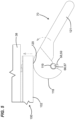
- the clamp system 32 includes a separate maintenance tool 70.
- the maintenance tool 70 is constructed and arranged to engage each of the first and second pivot rods 58, 59 and apply an axial force against the omega clamp 100 during servicing of the second filter elements 22.
- the maintenance tool 70 includes a head 118 defining a recess 119 sized to engage the first and second pivot rods 58, 59.
- the head 118 includes a cam surface 120 on a portion of the head 118 opposite of the recess 119.
- the maintenance tool 70 also includes a grasping handle 121 sized to be gripped by a human hand. The grasping handle 121 extends from the head 118.
- the maintenance tool 70 can be used so that the recess 119 is placed on the barrel nut 66, 67 of a respective one of the pivot rods 58, 59.
- the maintenance tool 70 is then rotated or pivoted about the barrel nut 66, 67, and this moves the camming surface 120 against the omega clamp 100.
- the camming surface 120 can be moved to provide a force against the base 102 of the omega clamp 100. This then applies pressure to the frame 38 of the second element 22 to press against the gasket 40 of the second element 22.
- FIG. 3 shows a portion of the system when the first element 20 and second element 22 are in place, and the clamp system 32 is engaged securing both elements 20, 22 in place.
- the pin 95 of the first slide pin arrangement 86 can be seen in a locked position, in which it is in the position to the most outside portion of the first slide 98. It is being held by the first slider keeper 112.
- the first pivot rod 58 can been seen extending through the hole 114 in the omega clamp 100.
- the flange 80 of the first clamp 74 can be seen pressing against the frame 34 of the first filter element 20.
- the first step is to slide the first and second clamps 74, 75 in an outward direction from the rest of the assembly, such that they are slid away from each other and toward the outside.
- This can be seen in FIG. 2 , in which the clamps 74, 75 have been slid away so that the flanges 80, 81 are away from what would be the frame 34 of the first filter element 20.
- This step allows the second filter element 22 to remain in sealing engagement on the support grid 24, but releases the first element 20 so that it can be removed.
- a new, replacement first element 20 can be provided.
- the new first element 20 is placed so that the perimeter frame 34 of the first element 20 holding the gasket 36 can be placed against the first side of the perimeter frame 38a.
- the replacement filter element 20 can be axially pressed against the frame 38a of the second element 22, and then the first and second clamps 74, 75 can again be slid inwardly toward each other so that the flanges 80, 81 are resting against the perimeter frame 34 on the second side 34b of the perimeter frame 34 that is opposite from the first side 34a on which the gasket 36 is located.
- the flanges 80, 81 help to hold the first element 20 in place, with a seal formed against the frame 38 (second side 38b) of the second element 22. See FIG. 7 .
- the gas turbine inlet system is shut down.
- the first filter element 20 is removed, by the steps above. That is, the first and second clamps 74, 75 are moved away from each other to the outside, which allows for release and removal of the first element 20.
- the maintenance tool 70 is used to press the omega clamp 100 against the perimeter frame 38 of the second element 22 and compress the gasket 40 of the second element 22 to a maximum displacement.
- the maintenance tool 70 is used by placing the recess 119 against the barrel nut 66, 67 and pivoting the maintenance tool 70 so that the cam surface 120 presses against the base 102 of the omega clamp 100.
- the pins 95, 96 are moved or slid toward each other to the inside within their respective slots 98, 99. This releases the pin flanges 93, 94 from the pin slider keepers 112, 113. This also releases the omega clamp 100 from the support tube 45.
- the omega clamp 100 can then be pulled and lifted out of the way of the second filter element 22.
- it can be pivoted in the direction of arrows 63, 64 ( FIG. 4 ) and along the pivot axis 62 either upwardly as shown in FIG. 6 or downwardly, along with pivot rods 58, 59. This then allows access to the second element 22, so that the second element 22 can be removed from the support grid 24.
- a new second element 22 is provided and placed in the opening 28.
- the gasket 40 is pressed against the first side 29 of the support grid 24.
- the omega clamp 100 is then pivoted over the perimeter frame 38 of the second element 22 so that the gasket 40 of the second element 22 is pressed between and against the perimeter frame 38 (i.e., second side 38b) of the second element 22 and the support grid 24.
- the first element 20 is then placed directly across and in opposition to the second element 22 so that the gasket 36 of the first element 20 is pressed against the frame 38 (i.e., first side 38a) of the second element 22.
- the first and second clamps 74, 75 are then moved to the inside so that the flanges 80, 81 press against the second side 34b and hold the perimeter frame 34 of the first element 20.
- a gas turbine air inlet system is shown at 200.
- the gas turbine air inlet system 200 is similar to that as described in U.S. 8,673,040 .
- the support grid 24 includes frame 26 having upstream side 29 and opposite downstream side 30. Each opening in the support grid 24 accommodates at least one first filter element 202 on the upstream side 29 and one second filter element 204 on the downstream side 30.
- the support grid 24 includes a matrix of several, for example hundreds, of first filter elements 202 on the upstream side 29 and second filter elements 204 on the downstream side 30.
- first filter element 202 and second filter element 204 are typically oriented on the support grid 24 directly across from each other and covering one of the openings 28 in the support grid 24.
- the first filter elements 202 comprise pocket filter elements 205, while the second filter elements 204 comprise v-bank filter elements 206.
- Example pocket filter elements are described in US 7,931,723 ,.
- Example v-bank filter elements are described in US 8425644 , US 10486094 , US 7334490 , US 9623356 , and US8951321 .
- the first filter elements 202 could also be v-bank filter elements.
- the first filter element 202 and the second filter element 204 each has a perimeter gasket 201, 203, which is constructed and arranged to be axially pressed to form a seal.
- a single clamp system 210 is used to releasably secure both a first filter element 202 and second filter element 204 to the frame 26 of the support grid 24.
- clamp system 210 is depicted.
- the clamp system 210 releasably attaches the filter assembly, comprising the first filter element 202 and the second filter element 204 to the support grid 24.
- the clamp system 210 includes a plurality of clamp rods 212, 214.
- each clamp system 210 includes two clamp rods 212, 214.
- the clamp rods 212, 214 will generally be non-removably secured to the frame 26 to project therefrom.
- Each of the rods 212, 214 has a cylindrical base 216 extending from a grid engaging portion to about halfway of the length of the rod 212, 214.
- the other half of the rod 212, 214 extending to a free (terminal) end has a narrowed section 218 being a handgrip-engaging section 218 shaped to receive one of the handgrips 220, 222.
- the narrowed section 218 comprises a projection 219 extending from a side or lateral portion thereof.
- the support tube 224 can have a single ( FIGS. 45-49 ) or a plurality of openings.
- the openings 232, 234 match up and are in axial alignment with the clamp rods 212, 214.
- Each opening 232, 234 is sized to receive or be fit over one of the clamp rods 212, 214. Openings 232, 234 also extend through the flange plate 230.
- the clamp system 210 further includes a first slide plate 236.
- the first slide plate 236 is removably and slidably mounted in the first support tube 224.
- the first slide plate 236 is insertable through the open end 228 and is within the rectangular wall 226.
- the first slide plate 236 has openings shown at 238, 240.
- the openings 238, 240 are alignable with the openings 232, 234 of the first support tube 224.
- the openings 238, 240 can be shaped to assist with locking the second filter element 204 in sealing engagement with the grid 24, as further describe below.
- the openings 238, 240 have a narrowed region 242 and a wider region 244.
- the first slide plate 236 further includes an end handle 246.
- the end handle 246 will project out of the first support tube 224 extending from the open end 228, when the first slide plate 236 is positioned within the first support tube 224.
- the end handle 246 can be used to move the slide plate 236 between the locked and unlocked position.
- the end handle 246 is generally perpendicular to a remaining portion of the first slide plate 236.
- the clamp system, 210 further includes a second elongated support profile, member, or tube 250.
- the second support tube 250 further includes a plurality of openings shown at opening 252 and 254. Each opening 252, 254 is arranged and sized to fit over one of the clamp rods 212, 214.
- the second support tube 250 has a rectangular cross-sectional wall 256.
- the wall 256 has opposite open ends 257, 258.
- the openings 252, 254 extend through opposing sides of the wall 256.
- FIG. 18 Also shown in FIG. 18 is a mounting plate 260 with posts 262, 264 projecting therefrom.
- Mounting bases 266, 268 receive the posts 262, 264.
- the mounting bases 266, 268 are secured to the rods 212, 214.
- the assembly including the plate 260 with posts 262, 264 and mounting bases 266, 268 are secured to or can be integral with the support grid 24. Many variations are possible.
- the hand grips 220, 222 are analogous to the maintenance tool 70 described previously.
- the hand grips 220, 222 are constructed and arranged to engage one of the clamp rods 212, 214 and apply an axial force against the support tube 250.
- the hand grips 220, 222 each include a head 270.
- the head 270 defines a recess 272 sized to engage the grip engaging section or narrower section 218 of the rods 212, 214.
- Each head 270 further includes a cam surface 275 in the form of a flattened area and on a portion of the head 270 that is opposite of the recess 272.
- a grasping handle 276 is sized for comfortable gripping by a human hand extends from the head 270.
- each hand grip 220, 222 has its head 270 split into head pieces 277, 278. Between the head pieces 277, 278 is a receiving slot 280.
- the receiving slot 280 is sized to fit around the hand grip engaging section 218 of the rods 212, 214.
- Each head piece 277, 278 includes recessed 272, which will hook onto the projection 219 of the rods 212, 214.
- the hand grips 220, 222 can be fit around the rods 212, 214 such that the recess 272 in the head 270 will engage the projection 219, and the hand grip 220 can be pivoted from an unlocked position shown at 282 in FIGS. 9 and 17 to a locked 284 also shown in FIG. 9 .
- the unlocked position includes the cam surface 272 being out of engagement with the second support tube 250 and the handles 276 extending away from the support grid 24.
- the locked position 284 include the cam surface 274 being against the second support tube 250 and the handles 276 generally pointing to each other and almost generally parallel to the support grid 24.
- the second filter element 204 is initially placed through one of the openings in the support grid 24 such that it is on the downstream side 30, with its gasket 203 on the upstream side 29 and against the frame 26.
- the first support tube 224 along with the first slide plate 236, is then placed over the rods 212, 214, such that the flange plate 230 of the support tube 224 is against a header frame of the second filter element 204.
- the slide plate 236 can then be moved or slid by pulling on end handle 246 in a direction laterally outwardly from the second filter element 204.
- the gasket 203 is not yet compressed.
- the second support profile or tube 250 is placed over the rods 212, 214, and the hand grips 220, 222 are loosely fit onto the clamp rods 212, 214.
- the first filter element 202 is then installed by placing the header frame of the first filter element 202 underneath the second support tube 250.
- the hand grips 220, 222 are then rotated from a position where the handles 276 are generally perpendicular to the frame 26, to a position in which the handles 276 are generally parallel to the frame 26. This will compress both of the gaskets 201, 203 of the first filter element 202 and second filter element 204.
- the slide plate 236 is moved or slid by grasping the end handle 246 and moving it in a direction toward the elements 202, 204, which keeps the second filter element 204 clamped with the gasket 203 in the compressed state and allows for online changing of the first filter elements 202.
- the process is done in reverse, by releasing the clamp system 210 holding both the first filter element 202 and second filter element 204 in place and in sealing engagement on the support grid 24. While the second filter element 204 remains in sealing engagement, the first filter element 202 is removed. A replacement first filter element 202 is provided and the single clamp system 210 is engaged to seal the replacement first filter element 202 to the support grid 24.
- the step of engaging the single clamp system 210 can include grasping the hand grips 220, 222 and rotating the hand grips 220, 222 from an open position to a closed position to apply an axial force against the clamp system 210. After rotating the hand grips 220, 222, the first slide plate 236 can be moved to lock the second filter element 204 into a sealed position against the support grid 24.
- the second filter element 204 can also be replaced. This is done by, after removing the first filter element 202, sliding the slide plate 236 to an unlocked or released position by moving it laterally (sideways) away from the elements 202, 204. This releases the seal of the gasket 203 on the second element 204.
- the first support tube 224 can then be removed, which allows the second filter element 204 to be removed from the frame 26.
- a replacement second element 204 is then provided and inserted into the opening in the frame 26, with the gasket 203 against the upstream side 29 of the frame 26.
- the first support tube 224 is again mounted onto the rods 212, 214.
- the second support tube 250 is then mounted onto the rods 212, 214, and the first filter element 202 is oriented so that the gasket 201 is between the first support tube 224 and second support tube 250.
- the hand grips 220, 222 are rotated such that the cam surface 274 is moved against the second support tube 250 to apply axial force to the first and second support tubes 224, 250 compressing the gaskets 201, 203.
- the first slide plate 236 is then moved into a locked position, sliding in a direction toward the elements 202, 204.
- FIGS. 20-39 an alternative embodiment for the clamp system 210 is provided, depicted generally at 201'.
- the difference between the clamp system 210 and clamp system 210' is the existence of a second slide plate 300 ( FIG. 38 ).
- the second slide plate 300 is held by the second support tube 250 and is positioned over the clamp rods 212, 214.
- the second slide plate 300 includes an end handle 302 projecting generally perpendicular to a remaining portion thereof.
- both the first slide plate 236 and second slide plate 300 are moved or slid into the locked position, in which the first slide plate 236 secures that gasket 203 of the second filter element 204 into a sealed position, and the second slide plate 300 secures the gasket 201 of the first filter element 202 into a sealed position, after that, the hand grips 220, 222 are removable from the overall system, and both the first filter element 202 and the second filter element 204 are secured in place.
- the motion to move the first slide plate 236 and second slide plate 300 to the locked position includes moving the slide plates 236, 300 laterally outwardly, in a direction away from the filter elements 202, 204.
- the end handles 246, 302 are on opposite sides of the elements 202, 204 and are moved away from each other when being moved to the locked position.
- this motion could be reversed - that is, instead of moving the slide plates 236, 300 laterally away from each other to the locked position, they could be designed oppositely so that moving the slide plates 236, 300 laterally toward each other results in the locked position.
- the second slide plate 300 is slid by moving it inwardly toward a direction of the first filter element 202 and second filter element 204. This will allow the second support tube 250 to be lifted or pivoted and remove the first filter element 202. A replacement first filter element 202 then can then be provided and oriented with the gasket 201 between the first support tube 224 and the second support tube 250. The hand grips 220, 222 can then again be engaged with the rods 212, 214 and rotated to compress the second support tube 250 against the gasket 201 of the first filter element 202. The second slide plate 300 can then be moved to lock the first filter element 202 into a sealed position.
- the second filter element 204 will also be replaced, and, after removing the first filter element 202 as described above, the second filter element 204 can be removed and replaced, as described in detail with respect to the embodiment of FIGS. 9-19 .
- FIGS. 40-44 show a variation of the embodiment of FIGS 9-19 , with the same reference numerals being used to show similar parts.
- this embodiment instead of having the second support member 250, there is a second support member 250' having the same profile shape as the first elongated support member 224.
- FIGS. 45-49 show a variation of the embodiment of FIGS 9-19 , with the same reference numerals being used to show similar parts.
- this embodiment instead of having a pair of handgrips 220, 222, there is a single handgrip 220' centered on the support members 224, 250. There is also only a single clamp rod 212' fixed to the grid 26, horizontally centered for each filter 204, 205.
- FIGS. 50-57 show a variation of the embodiment of FIGS 9-19 , with the same reference numerals being used to show similar parts.
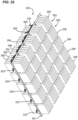
- both the first filter element 202 and the second filter element 204 are V-bank filter elements 206. There is greater horizontal and vertical spacing between each element 206, than in the embodiment of FIGS. 9-19 , one of the purposes being to accommodate additional handgrips, as explained below.
- the system 200 includes handgrips 223 along the lateral sides of each element 206 to help hold the elements 206 in place on the frame 26. Extending from vertically members of frame 26 are connector rods 213 that engage with handgrips 223. There are also clamp members 285, 286 to help clamp the elements 206 in place against the element frame headers 287, 288.
- the air filtration systems above can be used in a variety of environments and systems.
- the air filtration systems described above can be used to filter incoming air to prevent airborne viruses.
- Such applications can include livestock environments, such as swine farms, poultry, and other livestock in which airborne viruses could transmit.
- Static positive pressure air filtration systems using small turbine units can be used.
- Filter elements with filtration ratings from MERV 14 to HEPA can be applied to capture relevant airborne viruses.
- One unit can providing 250,000 CFM with 90 filter elements, and multiple units can be configured to meet overall air flow requirements based on livestock population to be housed.
- a positive pressure filtration system is used, which results in a smaller system, and has advantages of ease of maintenance and better security during changeover. It will have up to 1.0 inch of water positive pressure differential, and less than 300 filter units.
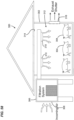
- the barn 302 can be for a variety of livestock such as swine 304, or can be for poultry (e.g., chickens, turkeys), sheep, goats, cattle / bovines, horses, etc.
- poultry e.g., chickens, turkeys
- sheep, goats e.g., sheep, goats
- cattle / bovines e.g., horses, etc.
- the system 300 includes filtration system 306, which can include any of the systems described above in connections with FIGS. 1-57 .
- the filtration system 306 draws in air from the outside atmosphere at an inlet region 308.
- the air is filtered to remove contaminants, including viruses, and the filtered air exits through an outlet region 310 in the interior 312 of the barn 302.
- the outlet region 310 is adjacent a ceiling 314 of the livestock area in the interior 312 of the barn 302.
- Interior air from the interior 312 of the barn 302 is exhausted to the outer atmosphere from the barn 302 through an exhaust shutter 316.
Landscapes
- Chemical & Material Sciences (AREA)
- Chemical Kinetics & Catalysis (AREA)
- Engineering & Computer Science (AREA)
- Combustion & Propulsion (AREA)
- Mechanical Engineering (AREA)
- General Engineering & Computer Science (AREA)
- Filtering Of Dispersed Particles In Gases (AREA)
Description
- This disclosure relates to air filter systems. In certain applications, it concerns air filters for use in air intake of gas turbine systems and a clamp arrangement. Methods are also provided.
- Although the present disclosure may be applied in a variety of applications, it was developed for use with gas turbine filter systems. Gas turbine systems are useful in generating electricity. These types of systems are convenient in that they can be constructed quickly and they produce fewer harmful emissions than coal or oil. Gas turbines utilize air for combustion purposes. The combustion air needs to be clean. To ensure clean air for combustion, air filters have been used to clean the air taken into the gas turbine system.
- Filters are used to purify the air intake for gas turbines. An example gas turbine air intake system is disclosed in
U.S. 8,673,040 . Another example is disclosed inUS 2014/096493 . - The air filters used in these intake systems need to be periodically removed and replaced. It is desirable to find a convenient system for allowing for the quick and easy servicing of these air filters. In particular, it is desirable to have a system in which a single clamp system can be used for both the first filter and second filter, and allow the second filter to remain sealed in placed while the first filter is being serviced.
- This disclosure provides a solution to the problem in the prior art in the form of a clamp system according to claim 1, a filter system according to claim 8 and a method of servicing a filter arrangement according to claim 15.
- For example, the solution provided herein allows for a single clamp that seals both a first filter
and second filter to the support grid of an intake air system of a gas turbine and also allows for keeping the second filter in sealing engagement with the support grid while releasing the first filter for replacement. The clamp can also selectively release the second element for periodic removal and replacement. - In a first aspect, not part of the claimed invention, a clamp system for releasably attaching a filter assembly to a support grid is provided; the clamp system includes: (a) an elongated support member with first and second opposite open ends, a first slide channel adjacent the first end; and a second slide channel adjacent the second end; (b) a first clamp slidably mounted in the first open end; (c) a second clamp slidably mounted in the second open end; (d) a first slide pin arrangement slidably mounted in the first slide channel between a locked and a released position; (e) a second slide pin arrangement slidably mounted in the second slide channel between a locked and a released position; (f) an elongated omega clamp removably mounted to cover the support member; the omega clamp having first and second spaced through slots; (i) the first through slot slidably accommodating a portion of the first slide pin arrangement; (ii) the second through slot slidably accommodating a portion of the second slide pin arrangement; (g) first and second pivot rods extending through and connecting the omega clamp and the support member; the first and second pivot rods each having a hinge point in the support member and a pivot axis along a length of the support member between the first and second open ends of the support member; wherein, when the first and second slide pin arrangements are slid to the released position, the omega clamp is free to be pivoted with the first and second pivot rods along the pivot axis away from covering the support member.
- The clamp system can further include a separate maintenance tool constructed and arranged to engage each of the first and second pivot rods and apply an axial force against the omega clamp.
- The maintenance tool can include (a) a head defining a recess sized to engage the first and second pivot rods, and a cam surface on a portion of the head opposite of the recess; and (b) a grasping handle extending from the head.
- Each of the first and second pivot rods includes a barrel nut on a portion of the pivot rods opposite of the hinge point.
- Each of the first clamp and second clamp includes: (a) a slide rod sized to be slidably received within one of the first and second open ends of the support member; (b) a post secured to and perpendicular to the slide rod; and (c) a flange secured to a distal portion of the post and parallel to and facing the slide rod to form a gasket holding recess therebetween.
- Each of the first and second slide pin arrangements includes: (a) a pin slide rod sized to slide within one of the first and second slide channels; (b) a support secured to and perpendicular to the pin slide rod; (c) a pin flange secured to a distal portion of the support and parallel to the pin slide rod with an interior side facing the pin slide rod and an opposite exterior side; and (d) pin projecting from the exterior side and sized to slide within one of the first and second slots in the omega clamp.
- The omega clamp comprises: (a) a base with a pair of legs extending perpendicular to the base; (i) the base defining the first and second through slots; (ii) the base having an exterior side and an opposite interior side; (b) each of the legs being bent at a non-zero angle remote from the base and away from each other; the legs and the interior side of the base defining an open channel; and (c) first and second pin slider keepers secured to the interior side of the base and overlapping a portion of the first and second through slots.
- The omega clamp comprises: (a) a base with a pair of legs extending perpendicular to the base; (i) the base defining the first and second through slots; (ii) the base having an exterior side and an opposite interior side; (b) each of the legs being bent at a non-zero angle remote from the base and away from each other; the legs and the interior side of the base defining an open channel; and (c) first and second pin slider keepers secured to the interior side of the base and overlapping a portion of the first and second through slots; (i) the first and second pin slider keepers being sized to slidably receive one of the pin flanges to put the first and second slide pin arrangements in the locked positions; and wherein when the first and second slide pin arrangements are slid to the released position, each of the pin flanges are slid to be free of the first and second pin slider keepers, and the omega clamp is free to be pivoted with the first and second pivot rods along the pivot axis away from covering the support member.
- In another aspect, not part of the claimed invention, a clamp system for releasably attaching a filter assembly to a support grid is provided comprising: (a) a support member; (b) first and second clamps slidably mounted at opposite ends of the support member; (c) a first and second slide pin arrangements slidably mounted a portion of the support member; (d) an omega clamp removably mounted to cover the support member and slidably accommodating a portion of the first and second slide pin arrangement; (e) first and second pivot rods extending through and connecting the omega clamp and the support member; the first and second pivot rods each having a hinge point in the support member and a pivot axis along a length of the support member between opposite ends of the support member; and wherein, when the first and second slide pin arrangements are slid to a released position, the omega clamp is free to be pivoted with the first and second pivot rods along the pivot axis away from covering the support member.
- In another aspect, not part of the claimed invention, a filter system is provided comprising: (a) a support grid having a frame with opposite first and second sides; (b) a first filter element oriented along the first side of the support grid; (c) a second filter oriented on the support grid directly across and opposing the first filter; and (d) a single clamp system releasably securing both the first filter element and the second filter element to the frame.
- The clamp system comprises: (a) a support member; (b) first and second clamps slidably mounted at opposite ends of the support member; (c) a first and second slide pin arrangements slidably mounted a portion of the support member; (d) an omega clamp removably mounted to cover the support member and slidably accommodating a portion of the first and second slide pin arrangement; (e) first and second pivot rods extending through and connecting the omega clamp and the support member; the first and second pivot rods each having a hinge point in the support member and a pivot axis along a length of the support member between opposite ends of the support member; and wherein, when the first and second slide pin arrangements are slid to a released position, the omega clamp is free to be pivoted with the first and second pivot rods along the pivot axis away from covering the support member.
- The clamp system includes: (a) an elongated support member with first and second opposite open ends, a first slide channel adjacent the first end; and a second slide channel adjacent the second end; (b) a first clamp slidably mounted in the first open end; (c) a second clamp slidably mounted in the second open end; (d) a first slide pin arrangement slidably mounted in the first slide channel between a locked and a released position; (e) a second slide pin arrangement slidably mounted in the second slide channel between a locked and a released position; (f) an elongated omega clamp removably mounted to cover the support member; the omega clamp having first and second spaced through slots; (i) the first through slot slidably accommodating a portion of the first slide pin arrangement; (ii) the second through slot slidably accommodating a portion of the second slide pin arrangement; (g) first and second pivot rods extending through and connecting the omega clamp and the support member; the first and second pivot rods each having a hinge point in the support member and a pivot axis along a length of the support member between the first and second open ends of the support member; wherein, when the first and second slide pin arrangements are slid to the released position, the omega clamp is free to be pivoted with the first and second pivot rods along the pivot axis away from covering the support member.
- The filter system can include (a) the first filter includes a perimeter frame with a gasket thereon; (b) the second filter includes a perimeter frame with a gasket thereon; and (c) a seal is formed with the first filter perimeter gasket being between and against the first and second clamps and the perimeter frame of the second filter.
- A seal is formed with the second filter perimeter gasket being between and against the omega clamp and the support grid frame.
- In one example, the first filter comprises a pocket filter; and the second filter comprises a pocket filter.
- In another aspect, not part of the claimed invention, a method of servicing a filter arrangement in a gas turbine air inlet system is provided; the system having a support grid having a frame with opposite first and second sides; a first filter element releasably sealed to the first side of the support grid; and a second filter releasably sealed to the first side of the support grid directly across and opposing the first filter; the method comprising: (a) releasing a single clamp holding both of the first filter element and second filter element in place in sealing engagement on the support grid; (b) while the second filter element remains in sealing engagement on the support grid, removing the first filter element; and (c) providing a replacement first filter element and engaging the single clamp to seal the replacement first filter element to the support grid.
- The method can further comprise: (a) before the step of providing a replacement first filter element, releasing another part of the single clamp to remove the second filter element; and (b) providing a replacement second filter element and engaging the single clamp to seal the replacement second filter element to the support grid.
- The method can further include using the single clamp as variously characterized above.
- In another aspect, according to claim 1, a clamp system for releasably attaching a filter assembly to a support grid is provided The clamp system comprising a plurality of clamp rods; a first elongated support member with openings, each opening being sized to fit over one of the clamp rods; a first slide plate slidably mounted in the first support member; the first slide plate having openings alignable with the openings in the first support member; the first slide plate having an end handle; a second elongated support member with openings, each opening in the second support member sized to fit over one of the clamp rods; and a plurality of handgrips, each handgrip constructed and arranged to engage one of the clamp rods and apply an axial force against the second support member.
- The clamp system can further include a second slide plate slidably mounted in the second support member; the second slide plate having openings alignable with the openings in the second support member; and the second slide plate having an end handle.
- In many examples, the handgrips each comprises: a head defining a recess sized to engage one of the clamp rods, and a cam surface on a portion of the head opposite of the recess; and a grasping handle extending from the head.
- The first support member may have a rectangular cross-sectional wall with opposite open ends, and the openings in the first support member extend through opposing sides of the wall; and the second support member may have a rectangular cross-sectional wall with opposite open ends, and the openings in the second support member extend through opposing sides of the wall of the second support member.
- In one or more examples, the first slide plate openings have a narrowed region and a wider region.
- In example embodiments, the second slide plate openings have a narrowed region and a wider region.
- There can be two clamp rods and two handgrips.
- In another aspect, according to claim 8, a filter system using a clamp system according to claim 1 is provided comprising: a support grid having a frame with opposite upstream and downstream sides; a first filter element oriented along the upstream side of the support grid; a second filter element oriented on the support grid on the downstream side directly across and opposing the first filter element; and a single clamp system releasably securing both the first filter element and the second filter element to the frame.
- The second filter element may have a second element gasket pressed against the upstream side of the support grid; and the first filter element may have a first element gasket pressed against the clamp system.
- In example embodiments, the clamp system comprises: one or more clamp rods extending from the support grid; a first elongated support member holding a first slide plate and positioned over the clamp rods; the first support member being positioned against the second element gasket; a second elongated support member positioned over the clamp rods and against the first element gasket, such that the first element gasket is positioned between and against the first support member and second support member; and one or more handgrips removably secured to the clamp rods and applying an axial force against the second support member.
- Further embodiments may comprise a second slide plate being held by the second support member and positioned over the clamp rods.
- In further embodiments there are a plurality of first filter elements on the upstream side of the support grid; and the first filter elements comprise pocket filter elements or V-bank elements.
- In further embodiments there are a plurality of second filter elements on the downstream side of the support grid; and the second filter elements comprise V-bank filter elements.
- In another aspect, a method of servicing a filter arrangement in a gas turbine air inlet system is provided; the system having a support grid having a frame with opposite upstream and downstream sides; a first filter element releasably sealed to the upstream side of the support grid; and a second filter element releasably sealed to the upstream side of the support grid directly across and opposing the first filter element; the method comprising: releasing a single clamp assembly holding both of the first filter element and second filter element in place in sealing engagement on the support grid; while the second filter element remains in sealing engagement on the support grid, removing the first filter element; and providing a replacement first filter element and engaging the single clamp assembly to seal the replacement first filter element to the support grid.
- The method may further comprise, before the step of providing a replacement first filter element, releasing another part of the single clamp assembly to remove the second filter element; and providing a replacement second filter element and engaging the single clamp assembly to seal the replacement second filter element to the support grid.
- In an embodiment not part of the claimed invention, the step of engaging the single clamp assembly to seal the replacement first filter element to the support grid includes grasping a handgrip and rotating the handgrip from an open position to a closed position to apply an axial force against the clamp assembly.
- In an embodiment not part of the claimed invention, the step of engaging the single clamp assembly can include, after rotating the handgrip to apply an axial force against the clamp assembly, moving a first slide plate to lock the second filter element into a sealed position against the support grid.
- In an embodiment not part of the claimed invention, the method can further include, after the step of moving a first slide plate to lock the second filter element into a sealed position against the support grid, moving a second slide pate to lock the first filter element into a sealed position; and rotating the handgrip back to the open position and removing the handgrip.
- In an embodiment not part of the claimed invention, the method can include the single clamp assembly as variously characterized above.
- A variety of examples of desirable features or methods are set forth in the description that follows.
-
-
FIG. 1 is a perspective, exploded view of a filter system for use with a gas turbine air system, the FIG. depicting a first filter element, a second filter element, a portion of the gas turbine support grid, and a clamp system; -
FIG. 2 is a perspective view of the system ofFIG. 1 , with the second filter element secured in place, and the first filter element being removed from the support grid; -
FIG. 3 is a perspective view of a portion of the system ofFIG. 1 with both the first filter element and second element in place against the support grid and the clamp system engaged securing both the first filter element and second filter element; -
FIG. 4 is an exploded, perspective view of the clamp system used inFIGS. 1-3 ; -
FIG. 5 is an enlarged front view of a portion of the clamp system during one step of servicing the second filter elements; -
FIG. 6 is a perspective view showing one step of servicing the second filter elements; -
FIG. 7 is an enlarged view showing a cross-section of both the first filter element and second filter element in sealing engagement against the support grid of the gas turbine air inlet system; and -
FIG. 8 is a schematic, perspective view showing the gasket of the first filter element, with the remaining part of the first filter element hidden to enhance clarity, and how it is held in place by the clamp system. -
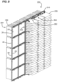
FIG. 9 is a perspective view of another embodiment of a gas turbine air inlet system, constructed in accordance with principles of this disclosure; -
FIG. 10 is the system ofFIG. 9 , but smaller, to show reference to additional drawings; -
FIG. 11 is an enlarged view of the portion shown at A ofFIG. 10 ; -
FIG. 12 is an enlarged view of the portion shown at B ofFIG. 10 ; -
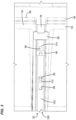
FIG. 13 is a top plan view of the system ofFIG. 9 , -
FIG. 14 is a cross-sectional view of a portion shown at cross section C-C ofFIG. 13 ; -
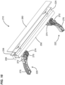
FIG. 15 is a perspective view showing a clamp system used in the air inlet system ofFIG. 9 ; -
FIG. 16 is another perspective view of the clamp system ofFIG. 15 ; -
FIG. 17 is a top plan view of the clamp system ofFIG. 15 ; -
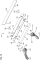
FIG. 18 is an exploded perspective view of the clamp system ofFIG. 15 ; -
FIG. 19 is another exploded perspective view of the clamp system ofFIG. 15 ; -
FIG. 20 is a perspective view of a clamp rod used in another embodiment of a clamp system shown inFIGS. 24-39 ; -
FIG. 21 is a perspective view of another clamp rod used in clamp system ofFIGS. 24-39 ; -
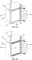
FIG. 22 is a perspective view of a portion of the air inlet system using the clamp system ofFIGS. 24-39 ; -
FIG. 23 is a view similar toFIG. 22 , but showing another part of the clamp system ofFIGS. 24-39 ; -
FIG. 24 is a perspective view of the clamp assembly used for the air inlet system ofFIGS. 22 and 23 ; -
FIG. 25 is an enlarged view of section A ofFIG. 24 ; -
FIG. 26 is a front view of the clamp system ofFIG. 24 ; -
FIG. 27 is a cross-sectional view of section 27-27 ofFIG. 26 ; -
FIG. 28 is a perspective view of the air inlet system during one step of applying the clamp system ofFIGS. 24-27 ; -
FIG. 29 is a perspective view showing another step of applying the clamp system ofFIGS. 24-27 ; -
FIG. 30 is a cross-sectional view of a portion of the clamp system shown inFIG. 29 ; -
FIG. 31 is a perspective view showing another step of applying the clamp system ofFIGS. 24-27 ; -
FIG. 32 is a perspective view of a portion of the air inlet system having the clamp system ofFIGS. 24-27 ; -
FIG. 33 is an enlarged perspective view of the portion shown at Y ofFIG. 32 ; -
FIG. 34 is an enlarged perspective view of the portion shown at Z ofFIG. 32 ; -
FIG. 35 is a perspective view showing the clamp system ofFIGS. 24-27 ; -
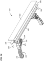
FIG. 36 is another perspective view of clamp system ofFIG. 35 ; -
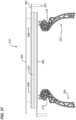
FIG. 37 is a top plan view of the clamp system ofFIG. 35 ; -
FIG. 38 is an exploded perspective view of the clamp system ofFIG. 35 ; -
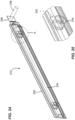
FIG. 39 is another exploded perspective view of the clamp system ofFIG. 35 ; -
FIG. 40 is an exploded perspective view of a variation of the system ofFIGS. 9-19 ; -
FIG. 41 is a perspective view of a portion of the system ofFIG. 40 ; -
FIG. 42 is an enlarged cross-sectional view of a portion ofFIG. 41 ; -
FIG. 43 is a top plan view of the system ofFIG. 40 ; -
FIG. 44 is an enlarged view of a portion ofFIG. 43 ; -
FIG. 45 is an exploded perspective view of a variation of the system ofFIGS. 9-19 ; -
FIG. 46 is a perspective view of a portion of the system ofFIG. 45 ; -
FIG. 47 is an enlarged cross-sectional view of a portion ofFIG. 46 ; -
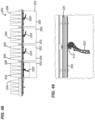
FIG. 48 is a top plan view of the system ofFIG. 45 ; -
FIG. 49 is an enlarged view of a portion ofFIG. 48 ; -
FIG. 50 is an exploded perspective view of a variation of the system ofFIGS. 9-19 ; -
FIG. 51 is a perspective view of a portion of the system ofFIG. 50 ; -
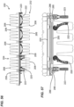
FIG. 52 is an enlarged cross-sectional view of a portion ofFIG. 51 ; -
FIG. 53 is an enlarged cross-sectional view of a portion ofFIG. 51 ; -
FIG. 54 is an enlarged cross-sectional view of a portion ofFIG. 51 ; -
FIG. 55 is a perspective view of the system ofFIG 51 ; -
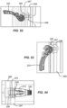
FIG. 56 is a top plan view of the system ofFIG. 55 ; -
FIG. 57 is an enlarged view of a portion ofFIG. 56 ; and -
FIG. 58 is a schematic view of an example system utilizing one or more of the filtration systems and components ofFIG. 1-57 . -
FIG. 1 shows a portion of a gas turbine air inlet system having afirst filter element 20 and asecond filter element 22.FIG. 1 also shows a portion of afirst filter element 20 both vertically above and below thefirst element 20 shown in its entirety. Similarly, thesecond filter element 22 also shows a portion of anothersecond element 22 both vertically above and vertically below it. - A variety of different types of filter elements can be used. In this particular example, the
first filter element 20 is a pocket filter element, such as shown and described inU.S. 7,931,723 . Thesecond filter element 22 can also be a pocket filter, although a number of different variations are possible. Each of theelements 20, - 22 has
filter media first filter element 20 could also be a v-bank filter. - In
FIG. 1 , a portion of asupport grid 24 having aframe 26 is shown. Thesupport grid 24 will include a matrix of several, for example hundreds, of rectangular grids withopenings 28. Eachopening 28 accommodates one of thesecond filters 22 and one of the first filters 20. In this example, thesupport grid 26 has opposite first andsecond sides first side 29 is generally an upstream side, while theside 30 is a downstream side. When installed, thefirst filter element 20 and thesecond filter element 22 will be oriented on thesupport grid 24 in opposition to each other, such that thefirst filter element 20 is on theupstream side 24, while thesecond filter element 22 is on thedownstream side 30. - Also visible in
FIG. 1 is aclamp system 32. Theclamp system 32 is shown at an upper portion ofFIG. 1 as being exploded from thesupport grid 24, while theclamp system 32 at a lower portion of the FIG. is shown secured to thesupport grid 24. Theclamp system 32 is a single clamp system that releasably secures the both thefirst filter element 20 and thesecond filter element 22 to theframe 26 of thesupport grid 24. - The
first filter element 20 includes aperimeter frame 34 all along each side of thefirst element 20. The perimeter frame includes a first side 34a (FIG. 7 ) facing away from thefilter media 21 and an oppositesecond side 34b facing toward thefilter media 21. Secured to theperimeter frame 34 on the first side 34a is a gasket 36 (FIGS. 7 and8 ).Gasket 36 is secured to theframe 34 on the first side 34a facing away from thefilter media 21 and is along the entire perimeter of thefirst element 20. Thegasket 36 can be made from a variety of materials, including a soft foam. - The
second element 22 includes aperimeter frame 38 as can be seen inFIG. 1 theperimeter frame 38 is along the entire perimeter of thesecond element 22. Theperimeter frame 38 includes afirst side 38a facing away from thefilter media 23, and an oppositesecond side 38b (FIG. 7 ) facing toward thefilter media 23. Secured to theperimeter frame 38 of thesecond element 22 is agasket 40. Thegasket 40 is not on theside 38a that is visible inFIG. 1 but can be seen in the cross-section inFIG. 7 at 38b. Thegasket 40 is on a portion of theframe 38 that faces a remaining part of thesecond element 22. As can be appreciated from reviewingFIG. 1 andFIG. 7 , thegasket 40 for thesecond filter element 22 is compressed against the first orupstream side 29 of theframe 26 of thesupport grid 24. Thegasket 36 of thefirst filter element 20 is then pressed against the frame 38 (first side 38a of the frame 38) of thesecond element 22. Theclamp 32 holds thefirst filter element 20 andsecond filter element 22 in place in sealing engagement against thesupport grid 24. - In general, in operation of the gas turbine air inlet system, air to be filtered enters the
first filter element 20, in which particulate and debris are removed by passing through thefilter media 21. The filtered air then flows through thesecond element 22 by flowing from inside of thesecond element 22 through themedia 23 to the outside on the downstream side, and then proceeds to the gas turbine. In this arrangement, thefirst filter element 20 is located generally on an upstream side of thesupport grid 24, while thesecond element 22 is primarily located on the downstream side of thesupport grid 24, although the seal made with thegasket 40 of thesecond element 22 is along the first orupstream side 29 of thesupport grid 24. - In reference now to
FIG. 4 , anexample clamp system 32 is illustrated in an exploded view. - The
clamp system 32 is used for releasably attaching the filter assembly, comprising thefirst element 20 and thesecond element 22 to thesupport grid 24. Theclamp system 32 allows for using thesingle system 32 to hold both thefirst filter element 20 and thesecond filter element 22 in place in sealing engagement on thesupport grid 24. While thesecond filter element 22 remains in sealing engagement on thesupport grid 24, theclamp system 32 can be released to allow for removal and replacement of thefirst filter element 20. Theclamp system 32 also allows for periodic removal and replacement ofsecond element 22. Typically, thefirst filter elements 20 need removal and replacement at more frequent intervals than thesecond elements 22. - The
clamp system 32 includes an elongated support member ortube 45. Thesupport tube 45 has first and second opposite open ends 46, 47. Thesupport tube 45 also includes afirst slide channel 48 adjacent to thefirst end 46, and asecond slide channel 49 adjacent thesecond end 47. The first andsecond slide channels tube 45 spaced from theends first enclosure 50 and asecond enclosure 51, such that the region between the ends of theenclosure - The
tube 45 further includes a throughhole 52 through theenclosure 50 and a remaining portion of thetube 45 and a throughhole 53 through theenclosure 51 and a remaining portion of thetube 45. The through holes 52, 53 receive projections or pegs 55, 56 (FIG. 1 ) extending from theframe 26 of thesupport grid 24. This allows for mounting of thetube 45 on and against theframe 26 of thegrid 24. - The
clamp system 32 further includes first andsecond pivot rods second pivot rods type hinge point support tube 45 within a respective one of theenclosures second pivot rods pivot axis 62 which is along a length of thesupport tube 45 between the first and second open ends 46, 47.Arrows rods - In addition, in
FIG. 4 , each of the first andsecond pivot rods barrel nut pivot rod maintenance tool 70, described further below. - The
clamp system 32 further includes afirst clamp 74 slidably mounted in the firstopen end 46 and asecond clamp 75 slidably mounted in the secondopen end 47. Each of thefirst clamp 74 andsecond clamp 75 includes aslide rod support tube 45. An extension or post 78, 79 is secured to and perpendicular to therespective slide rod flange respective post slide rod gasket holding recess second clamp first filter elements 20 in place in sealing engagement . - The
clamp system 32 further includes a first slide pin arrangement and a secondslide pin arrangement slide pin arrangement 86 is slidably mounted in thefirst slide channel 48 between a locked and a released position. The secondslide pin arrangement 87 is slidably mounted in thesecond slide channel 49 between a locked and released position. In the locked position, thesecond filter element 22 is secured in place against thegrid 24. In the unlocked position, thesecond filter element 22 can be removed from thegrid 24 for servicing (replacement). This is described further below. - Each of the first and second
slide pin arrangements pin slide rod second slide channels slide channels enclosures slide pin arrangements respective support pin slide rod - A
pin flange respective support pin slide rod pin flange pin slide rod pin flange slide pin arrangements pin pins pin flange second slots omega clamp 100. - The
clamp system 32 includeselongated omega clamp 100. Theomega clamp 100 is removably mounted to cover thesupport tube 45. Theomega clamp 100 includes a base 102 with a pair oflegs base 102. Thebase 102 defines the first and second throughslots pins FIG. 4 , theslots omega clamp 100 and also spaced from each other. - The base 102 had an exterior side 106 (
FIG. 7 ) and an opposite interior side 107 (FIG. 7 ). Each of thelegs base 102 and away from each other to formpressing flanges pressing flanges legs base 102, but many embodiments are possible. Thelegs interior side 107 of the base 102 define an open channel 110. - The
omega clamp 100 further includes first and secondpin slider keepers FIG. 4 , thepin slider keepers interior side 107 of thebase 102. Theslider keepers slots - The first and second
pin slider keepers pin flanges slide pin arrangements slide pin arrangements omega clamp 100 is free to be pivoted with the first andsecond pivot rods pivot axis 62 and away from covering thesupport tube 45. That is, when the first and secondpin slide arrangements pin flanges pin slider keepers omega clamp 100 is free to be pivoted along thepivot axis 62 in the direction ofarrow - When assembled, the first and
second pivot rods omega clamp 100 and thesupport tube 45. Thebase 102 of theomega clamp 100 includes throughholes pivot rods - Still in reference to
FIG. 4 , theclamp system 32 includes aseparate maintenance tool 70. Themaintenance tool 70 is constructed and arranged to engage each of the first andsecond pivot rods omega clamp 100 during servicing of thesecond filter elements 22. - The
maintenance tool 70 includes ahead 118 defining arecess 119 sized to engage the first andsecond pivot rods head 118 includes acam surface 120 on a portion of thehead 118 opposite of therecess 119. Themaintenance tool 70 also includes agrasping handle 121 sized to be gripped by a human hand. The graspinghandle 121 extends from thehead 118. - As can be seen in
FIG. 5 , themaintenance tool 70 can be used so that therecess 119 is placed on thebarrel nut pivot rods maintenance tool 70 is then rotated or pivoted about thebarrel nut camming surface 120 against theomega clamp 100. Specifically, thecamming surface 120 can be moved to provide a force against thebase 102 of theomega clamp 100. This then applies pressure to theframe 38 of thesecond element 22 to press against thegasket 40 of thesecond element 22. -
FIG. 3 shows a portion of the system when thefirst element 20 andsecond element 22 are in place, and theclamp system 32 is engaged securing bothelements pin 95 of the firstslide pin arrangement 86 can be seen in a locked position, in which it is in the position to the most outside portion of thefirst slide 98. It is being held by thefirst slider keeper 112. Thefirst pivot rod 58 can been seen extending through thehole 114 in theomega clamp 100. Theflange 80 of thefirst clamp 74 can be seen pressing against theframe 34 of thefirst filter element 20. - An example method of servicing the filter arrangement is now explained. In reference to
FIG. 2 , the first step is to slide the first andsecond clamps FIG. 2 , in which theclamps flanges frame 34 of thefirst filter element 20. This step allows thesecond filter element 22 to remain in sealing engagement on thesupport grid 24, but releases thefirst element 20 so that it can be removed. A new, replacementfirst element 20 can be provided. The newfirst element 20 is placed so that theperimeter frame 34 of thefirst element 20 holding thegasket 36 can be placed against the first side of theperimeter frame 38a. Thereplacement filter element 20 can be axially pressed against theframe 38a of thesecond element 22, and then the first andsecond clamps flanges perimeter frame 34 on thesecond side 34b of theperimeter frame 34 that is opposite from the first side 34a on which thegasket 36 is located. Theflanges first element 20 in place, with a seal formed against the frame 38 (second side 38b) of thesecond element 22. SeeFIG. 7 . - From time to time, it will also be desirable to service and replace the
second elements 22. During this maintenance step, the gas turbine inlet system is shut down. First, thefirst filter element 20 is removed, by the steps above. That is, the first andsecond clamps first element 20. Next, themaintenance tool 70 is used to press theomega clamp 100 against theperimeter frame 38 of thesecond element 22 and compress thegasket 40 of thesecond element 22 to a maximum displacement. Themaintenance tool 70 is used by placing therecess 119 against thebarrel nut maintenance tool 70 so that thecam surface 120 presses against thebase 102 of theomega clamp 100. - Next, the
pins respective slots pin flanges pin slider keepers omega clamp 100 from thesupport tube 45. - Reference is now made to
FIG. 6 . Theomega clamp 100 can then be pulled and lifted out of the way of thesecond filter element 22. In particular, it can be pivoted in the direction ofarrows 63, 64 (FIG. 4 ) and along thepivot axis 62 either upwardly as shown inFIG. 6 or downwardly, along withpivot rods second element 22, so that thesecond element 22 can be removed from thesupport grid 24. - A new
second element 22 is provided and placed in theopening 28. Thegasket 40 is pressed against thefirst side 29 of thesupport grid 24. Theomega clamp 100 is then pivoted over theperimeter frame 38 of thesecond element 22 so that thegasket 40 of thesecond element 22 is pressed between and against the perimeter frame 38 (i.e.,second side 38b) of thesecond element 22 and thesupport grid 24. Thefirst element 20 is then placed directly across and in opposition to thesecond element 22 so that thegasket 36 of thefirst element 20 is pressed against the frame 38 (i.e.,first side 38a) of thesecond element 22. The first andsecond clamps flanges second side 34b and hold theperimeter frame 34 of thefirst element 20. - In
FIG. 9 , a gas turbine air inlet system is shown at 200. The gas turbineair inlet system 200 is similar to that as described inU.S. 8,673,040 . There are rows and columns of filter elements arranged on a tube sheet or support grid, as described previously with respect to supportgrid 24. Thesupport grid 24 includesframe 26 havingupstream side 29 and oppositedownstream side 30. Each opening in thesupport grid 24 accommodates at least onefirst filter element 202 on theupstream side 29 and onesecond filter element 204 on thedownstream side 30. As can be seen inFIG. 9 , thesupport grid 24 includes a matrix of several, for example hundreds, offirst filter elements 202 on theupstream side 29 andsecond filter elements 204 on thedownstream side 30. - As depicted, the
first filter element 202 andsecond filter element 204 are typically oriented on thesupport grid 24 directly across from each other and covering one of theopenings 28 in thesupport grid 24. - Many different types of filter elements can be used. In the example shown, the
first filter elements 202 comprisepocket filter elements 205, while thesecond filter elements 204 comprise v-bank filter elements 206. Example pocket filter elements are described inUS 7,931,723 ,. Example v-bank filter elements are described inUS 8425644 ,US 10486094 US 7334490 ,US 9623356 US8951321 . In other embodiments, thefirst filter elements 202 could also be v-bank filter elements. - The
first filter element 202 and thesecond filter element 204 each has aperimeter gasket - As with the embodiment of
FIGS. 1-8 , asingle clamp system 210 is used to releasably secure both afirst filter element 202 andsecond filter element 204 to theframe 26 of thesupport grid 24. - In reference now to
FIGS. 16-19 ,clamp system 210 is depicted. Theclamp system 210 releasably attaches the filter assembly, comprising thefirst filter element 202 and thesecond filter element 204 to thesupport grid 24. Theclamp system 210 includes a plurality ofclamp rods - In the example shown, each
clamp system 210 includes twoclamp rods clamp rods frame 26 to project therefrom. Each of therods cylindrical base 216 extending from a grid engaging portion to about halfway of the length of therod rod section 218 being a handgrip-engagingsection 218 shaped to receive one of thehandgrips section 218 comprises aprojection 219 extending from a side or lateral portion thereof. - The
clamp system 210 further includes a first elongated support member ortube 224. Thefirst support tube 224 can be many different shapes having a variety of cross-sections. In the particular, non-limiting example shown, thefirst support tube 224 includes a generally rectangularcross-sectional wall 226 with opposite open ends 227, 228. Thewall 226 is positioned on aflange plate 230 supporting it along the length. - The
support tube 224 can have a single (FIGS. 45-49 ) or a plurality of openings. In the non-limiting example shown inFIGS. 9-19 , there are twoopenings openings clamp rods opening clamp rods Openings flange plate 230. - The
clamp system 210 further includes afirst slide plate 236. Thefirst slide plate 236 is removably and slidably mounted in thefirst support tube 224. In the example shown, thefirst slide plate 236 is insertable through theopen end 228 and is within therectangular wall 226. - The
first slide plate 236 has openings shown at 238, 240. Theopenings openings first support tube 224. Theopenings second filter element 204 in sealing engagement with thegrid 24, as further describe below. In the example shown, theopenings region 242 and awider region 244. - The
first slide plate 236 further includes anend handle 246. The end handle 246 will project out of thefirst support tube 224 extending from theopen end 228, when thefirst slide plate 236 is positioned within thefirst support tube 224. The end handle 246 can be used to move theslide plate 236 between the locked and unlocked position. The end handle 246 is generally perpendicular to a remaining portion of thefirst slide plate 236. - The clamp system, 210 further includes a second elongated support profile, member, or
tube 250. Thesecond support tube 250 further includes a plurality of openings shown atopening opening clamp rods - The
second support tube 250 has a rectangularcross-sectional wall 256. Thewall 256 has opposite open ends 257, 258. Theopenings wall 256. - Also shown in
FIG. 18 is a mountingplate 260 withposts bases posts bases rods plate 260 withposts bases support grid 24. Many variations are possible. - The hand grips 220, 222 are analogous to the
maintenance tool 70 described previously. The hand grips 220, 222 are constructed and arranged to engage one of theclamp rods support tube 250. - The hand grips 220, 222 each include a
head 270. Thehead 270 defines arecess 272 sized to engage the grip engaging section ornarrower section 218 of therods head 270 further includes a cam surface 275 in the form of a flattened area and on a portion of thehead 270 that is opposite of therecess 272. A graspinghandle 276 is sized for comfortable gripping by a human hand extends from thehead 270. - In
FIG. 19 , it can be seen how eachhand grip head 270 split intohead pieces head pieces slot 280. The receivingslot 280 is sized to fit around the handgrip engaging section 218 of therods head piece projection 219 of therods - In use, the hand grips 220, 222 can be fit around the
rods recess 272 in thehead 270 will engage theprojection 219, and thehand grip 220 can be pivoted from an unlocked position shown at 282 inFIGS. 9 and17 to a locked 284 also shown inFIG. 9 . The unlocked position includes thecam surface 272 being out of engagement with thesecond support tube 250 and thehandles 276 extending away from thesupport grid 24. The lockedposition 284 include thecam surface 274 being against thesecond support tube 250 and thehandles 276 generally pointing to each other and almost generally parallel to thesupport grid 24. - In the system of
FIGS. 9-19 , thesecond filter element 204 is initially placed through one of the openings in thesupport grid 24 such that it is on thedownstream side 30, with itsgasket 203 on theupstream side 29 and against theframe 26. Thefirst support tube 224 along with thefirst slide plate 236, is then placed over therods flange plate 230 of thesupport tube 224 is against a header frame of thesecond filter element 204. Theslide plate 236 can then be moved or slid by pulling onend handle 246 in a direction laterally outwardly from thesecond filter element 204. Thegasket 203 is not yet compressed. - Next, the second support profile or
tube 250 is placed over therods clamp rods first filter element 202 is then installed by placing the header frame of thefirst filter element 202 underneath thesecond support tube 250. The hand grips 220, 222 are then rotated from a position where thehandles 276 are generally perpendicular to theframe 26, to a position in which thehandles 276 are generally parallel to theframe 26. This will compress both of thegaskets first filter element 202 andsecond filter element 204. Next, theslide plate 236 is moved or slid by grasping theend handle 246 and moving it in a direction toward theelements second filter element 204 clamped with thegasket 203 in the compressed state and allows for online changing of thefirst filter elements 202. - To service the filter arrangement of
FIGS. 9-19 , the process is done in reverse, by releasing theclamp system 210 holding both thefirst filter element 202 andsecond filter element 204 in place and in sealing engagement on thesupport grid 24. While thesecond filter element 204 remains in sealing engagement, thefirst filter element 202 is removed. A replacementfirst filter element 202 is provided and thesingle clamp system 210 is engaged to seal the replacementfirst filter element 202 to thesupport grid 24. - The step of engaging the
single clamp system 210 can include grasping the hand grips 220, 222 and rotating the hand grips 220, 222 from an open position to a closed position to apply an axial force against theclamp system 210. After rotating the hand grips 220, 222, thefirst slide plate 236 can be moved to lock thesecond filter element 204 into a sealed position against thesupport grid 24. - Periodically, the
second filter element 204 can also be replaced. This is done by, after removing thefirst filter element 202, sliding theslide plate 236 to an unlocked or released position by moving it laterally (sideways) away from theelements gasket 203 on thesecond element 204. Thefirst support tube 224 can then be removed, which allows thesecond filter element 204 to be removed from theframe 26. A replacementsecond element 204 is then provided and inserted into the opening in theframe 26, with thegasket 203 against theupstream side 29 of theframe 26. Thefirst support tube 224 is again mounted onto therods second support tube 250 is then mounted onto therods first filter element 202 is oriented so that thegasket 201 is between thefirst support tube 224 andsecond support tube 250. The hand grips 220, 222 are rotated such that thecam surface 274 is moved against thesecond support tube 250 to apply axial force to the first andsecond support tubes gaskets first slide plate 236 is then moved into a locked position, sliding in a direction toward theelements - In reference now to
FIGS. 20-39 , an alternative embodiment for theclamp system 210 is provided, depicted generally at 201'. The difference between theclamp system 210 and clamp system 210' is the existence of a second slide plate 300 (FIG. 38 ). Thesecond slide plate 300 is held by thesecond support tube 250 and is positioned over theclamp rods second slide plate 300 includes anend handle 302 projecting generally perpendicular to a remaining portion thereof. In this system, after the hand grips 220, 222 are rotated into the locked position, both thefirst slide plate 236 andsecond slide plate 300 are moved or slid into the locked position, in which thefirst slide plate 236 secures thatgasket 203 of thesecond filter element 204 into a sealed position, and thesecond slide plate 300 secures thegasket 201 of thefirst filter element 202 into a sealed position, after that, the hand grips 220, 222 are removable from the overall system, and both thefirst filter element 202 and thesecond filter element 204 are secured in place. The motion to move thefirst slide plate 236 andsecond slide plate 300 to the locked position includes moving theslide plates filter elements elements slide plates slide plates - When the system of
FIGS. 20-39 is serviced, thesecond slide plate 300 is slid by moving it inwardly toward a direction of thefirst filter element 202 andsecond filter element 204. This will allow thesecond support tube 250 to be lifted or pivoted and remove thefirst filter element 202. A replacementfirst filter element 202 then can then be provided and oriented with thegasket 201 between thefirst support tube 224 and thesecond support tube 250. The hand grips 220, 222 can then again be engaged with therods second support tube 250 against thegasket 201 of thefirst filter element 202. Thesecond slide plate 300 can then be moved to lock thefirst filter element 202 into a sealed position. - Occasionally, the
second filter element 204 will also be replaced, and, after removing thefirst filter element 202 as described above, thesecond filter element 204 can be removed and replaced, as described in detail with respect to the embodiment ofFIGS. 9-19 . -
FIGS. 40-44 show a variation of the embodiment ofFIGS 9-19 , with the same reference numerals being used to show similar parts. In this embodiment, instead of having thesecond support member 250, there is a second support member 250' having the same profile shape as the firstelongated support member 224. -
FIGS. 45-49 show a variation of the embodiment ofFIGS 9-19 , with the same reference numerals being used to show similar parts. In this embodiment, instead of having a pair ofhandgrips support members grid 26, horizontally centered for eachfilter -
FIGS. 50-57 show a variation of the embodiment ofFIGS 9-19 , with the same reference numerals being used to show similar parts. - In this embodiment, both the
first filter element 202 and thesecond filter element 204 are V-bank filter elements 206. There is greater horizontal and vertical spacing between eachelement 206, than in the embodiment ofFIGS. 9-19 , one of the purposes being to accommodate additional handgrips, as explained below. - The
system 200 includeshandgrips 223 along the lateral sides of eachelement 206 to help hold theelements 206 in place on theframe 26. Extending from vertically members offrame 26 areconnector rods 213 that engage withhandgrips 223. There are also clampmembers elements 206 in place against theelement frame headers - The air filtration systems above can be used in a variety of environments and systems. For example, the air filtration systems described above can be used to filter incoming air to prevent airborne viruses. Such applications can include livestock environments, such as swine farms, poultry, and other livestock in which airborne viruses could transmit.
- Static positive pressure air filtration systems using small turbine units can be used. Filter elements with filtration ratings from MERV 14 to HEPA can be applied to capture relevant airborne viruses. One unit can providing 250,000 CFM with 90 filter elements, and multiple units can be configured to meet overall air flow requirements based on livestock population to be housed.
- In the prior art, a negative pressure air filtration with under 0.2 inch of water of pressure differential for sizing of the system is used. In these prior art systems, to provide high efficiency filtration and required flow, a significantly large systems are required. The systems described in this disclosure are about 1/3 of the size of prior art solutions with significantly reduced maintenance and operational resources.
- Using the air filtration systems of
FIGS. 1-57 , a positive pressure filtration system is used, which results in a smaller system, and has advantages of ease of maintenance and better security during changeover. It will have up to 1.0 inch of water positive pressure differential, and less than 300 filter units. - In reference now to
FIG. 58 , a system is shown at 300 having alivestock barn 302. Thebarn 302 can be for a variety of livestock such asswine 304, or can be for poultry (e.g., chickens, turkeys), sheep, goats, cattle / bovines, horses, etc. - The
system 300 includesfiltration system 306, which can include any of the systems described above in connections withFIGS. 1-57 . Thefiltration system 306 draws in air from the outside atmosphere at aninlet region 308. The air is filtered to remove contaminants, including viruses, and the filtered air exits through anoutlet region 310 in theinterior 312 of thebarn 302. As shown here, theoutlet region 310 is adjacent aceiling 314 of the livestock area in theinterior 312 of thebarn 302. Interior air from theinterior 312 of thebarn 302 is exhausted to the outer atmosphere from thebarn 302 through anexhaust shutter 316. - The above provides example principles of operation. Many embodiments can be made using these principles.
Claims (15)
- A clamp system (210) for releasably attaching a filter assembly to a support grid; the clamp system comprising:(a) one or more clamp rods (212, 214);(b) a first elongated support member (224) with openings (232, 234), each opening being sized to fit over one of the clamp rods;(c) a first slide plate (236) slidably mounted in the first support member;(i) the first slide plate having openings (238, 240) alignable with the openings in the first support member;(ii) the first slide plate having an end handle (246);(d) a second elongated support member (250) with openings (252, 254), each opening in the second support member sized to fit over one of the clamp rods; and(e) one or more handgrips (220, 222), each handgrip constructed and arranged to engage one of the clamp rods and apply an axial force against the second support member.
- The clamp system of claim 1 further comprising:(a) a second slide plate (300) slidably mounted in the second support member;(i) the second slide plate having openings alignable with the openings in the second support member; and(ii) the second slide plate having an end handle.
- The clamp system of any one of claims 1 and 2 wherein the handgrips each comprises:(a) a head (270) defining a recess sized to engage one of the clamp rods, and a cam surface on a portion of the head opposite of the recess; and(b) a grasping handle (276) extending from the head.
- The clamp system of any one of claims 1-3 wherein(a) the first support member has a rectangular cross-sectional wall with opposite open ends, and the openings in the first support member extend through opposing sides of the wall; and(b) the second support member has a rectangular cross-sectional wall with opposite open ends, and the openings in the second support member extend through opposing sides of the wall of the second support member.
- The clamp system of any one of claims 1-4 wherein the first slide plate openings have a narrowed region and a wider region.
- The clamp system of claim 2 wherein the second slide plate openings have a narrowed region and a wider region.
- The clamp system of any one of claims 1-6 wherein there are two clamp rods and two handgrips.
- A filter system using the clamp system of claim 1 comprising:(a) a support grid (24) having a frame with opposite upstream and downstream sides;(b) a first filter element (202) oriented along the upstream side of the support grid;(c) a second filter element (204) oriented on the support grid on the downstream side directly across and opposing the first filter element; and(d) a clamp system of claim 1 releasably securing both the first filter element and the second filter element to the frame.
- The filter system of claim 8 wherein:(a) the second filter element has a second element gasket (203) pressed against the upstream side of the support grid; and(b) the first filter element has a first element gasket (201) pressed against the clamp system.
- The filter system of any one of claims 8 and 9 wherein:(a) the one or more clamp rods extend from the support grid;(b) the first elongated support member hold a first slide plate and is positioned over the clamp rods;(i) the first support member being positioned against the second element gasket; and(c) the second elongated support member is positioned over the clamp rods and against the first element gasket, such that the first element gasket is positioned between and against the first support member and second support member.
- The filter system of claim 10 wherein the one or more handgrips are removably secured to the clamp rods and apply an axial force against the second support member.
- The filter system of any one of claims 10 and 11 further comprising a second slide plate being held by the second support member and positioned over the clamp rods.
- The filter system of any one of claims 8-12 wherein:(a) there are a plurality of first filter elements on the upstream side of the support grid; and(b) the first filter elements comprise pocket filter elements or V-bank filter elements.
- The filter system of any one of claims 8-13 wherein:(a) there are a plurality of second filter elements on the downstream side of the support grid; and(b) the second filter elements comprise V-bank filter elements.
- A method of servicing a filter arrangement in the filter system of claim 8; the method comprising:(a) releasing a single clamp system holding both of the first filter element and second filter element in place in sealing engagement on the support grid;(b) while the second filter element remains in sealing engagement on the support grid, removing the first filter element; and(c) providing a replacement first filter element and engaging the single clamp assembly to seal the replacement first filter element to the support grid.
Applications Claiming Priority (3)
| Application Number | Priority Date | Filing Date | Title |
|---|---|---|---|
| US202063035412P | 2020-06-05 | 2020-06-05 | |
| US202163140020P | 2021-01-21 | 2021-01-21 | |
| PCT/US2021/036006 WO2021248070A2 (en) | 2020-06-05 | 2021-06-04 | Clamp system and filter arrangement and methods |
Publications (3)
| Publication Number | Publication Date |
|---|---|
| EP4162154A2 EP4162154A2 (en) | 2023-04-12 |
| EP4162154B1 true EP4162154B1 (en) | 2025-06-04 |
| EP4162154C0 EP4162154C0 (en) | 2025-06-04 |
Family
ID=78830600
Family Applications (1)
| Application Number | Title | Priority Date | Filing Date |
|---|---|---|---|
| EP21735825.8A Active EP4162154B1 (en) | 2020-06-05 | 2021-06-04 | Clamp system and filter arrangement and methods |
Country Status (4)
| Country | Link |
|---|---|
| US (1) | US12383854B2 (en) |
| EP (1) | EP4162154B1 (en) |
| CN (1) | CN115968423B (en) |
| WO (1) | WO2021248070A2 (en) |
Family Cites Families (19)
| Publication number | Priority date | Publication date | Assignee | Title |
|---|---|---|---|---|
| US7332012B2 (en) * | 2004-07-21 | 2008-02-19 | Aaf-Mcquay Inc. | Multi-stage filtering apparatus |
| ATE531440T1 (en) | 2005-03-31 | 2011-11-15 | Donaldson Co Inc | AIR PURIFIER ARRANGEMENT |
| SG164301A1 (en) | 2005-10-24 | 2010-09-29 | Camfil Farr Inc | Method and apparatus for v-bank filter bed scanning |
| US7931723B2 (en) | 2006-03-09 | 2011-04-26 | Donaldson Company, Inc. | Filter assembly with pleated media pockets, and methods |
| US8425644B2 (en) | 2008-01-31 | 2013-04-23 | Anders Sundvik | High flow V-bank filter |
| US8673040B2 (en) | 2008-06-13 | 2014-03-18 | Donaldson Company, Inc. | Filter construction for use with air in-take for gas turbine and methods |
| US8105409B2 (en) * | 2009-01-30 | 2012-01-31 | General Electric Company | Filter retention system |
| US8052770B2 (en) * | 2009-03-13 | 2011-11-08 | General Electric Company | Filter retainer for turbine engine |
| US8048186B2 (en) * | 2009-04-02 | 2011-11-01 | General Electric Company | Filter retention systems and devices |
| US8956434B2 (en) * | 2009-06-22 | 2015-02-17 | Donaldson Company, Inc. | Filter element support assembly, quick installation system, and methods |
| US8303678B2 (en) * | 2009-12-30 | 2012-11-06 | General Electric Company | Intake air filter system |
| GB2491581A (en) | 2011-06-03 | 2012-12-12 | Aaf Ltd | Filter assembly |
| EP2800617B1 (en) | 2012-01-02 | 2020-06-17 | Camfil USA, Inc. | V-bank filter assembly with replaceable filters |
| US9205359B2 (en) * | 2012-10-09 | 2015-12-08 | W.L. Gore & Associates, Inc. | V-panel filters |
| EP3197583B1 (en) * | 2014-09-25 | 2018-11-21 | Camfil AB | V-type filter frame |
| CN107580521A (en) | 2015-05-15 | 2018-01-12 | 3M创新有限公司 | Collapsible V-type filter |
| US10512865B2 (en) * | 2017-02-06 | 2019-12-24 | Bha Altair, Llc | Devices and methods for aligning filters in a holding frame |
| US10434449B1 (en) * | 2017-07-26 | 2019-10-08 | Alan Coupal | Filter retaining mechanism with filter/pre-filter clip |
| US20230175717A1 (en) * | 2021-12-07 | 2023-06-08 | Donaldson Company, Inc. | Air filtration for livestock |
-
2021
- 2021-06-04 CN CN202180039822.9A patent/CN115968423B/en active Active
- 2021-06-04 WO PCT/US2021/036006 patent/WO2021248070A2/en not_active Ceased
- 2021-06-04 EP EP21735825.8A patent/EP4162154B1/en active Active
- 2021-06-04 US US18/000,788 patent/US12383854B2/en active Active
Also Published As
| Publication number | Publication date |
|---|---|
| WO2021248070A2 (en) | 2021-12-09 |
| CN115968423B (en) | 2025-11-11 |
| WO2021248070A3 (en) | 2022-02-03 |
| US20230211271A1 (en) | 2023-07-06 |
| CN115968423A (en) | 2023-04-14 |
| EP4162154A2 (en) | 2023-04-12 |
| US12383854B2 (en) | 2025-08-12 |
| EP4162154C0 (en) | 2025-06-04 |
Similar Documents
| Publication | Publication Date | Title |
|---|---|---|
| US9370740B2 (en) | Modular stacking filter system | |
| US8062402B2 (en) | Filter holding frame with clamping mechanism | |
| CN104138692B (en) | Filter element, dust arrester and method | |
| US20140130468A1 (en) | Filter assembly, and pre-filter device and pre-filter mounting plate therefor | |
| CN102803682B (en) | Filter element support assembly, quick installation system and method | |
| EP3577327B1 (en) | Devices and methods for aligning filters in a holding frame | |
| US9682338B2 (en) | Filter frame adapter | |
| CN209934310U (en) | Flue gas purifying equipment | |
| EP4162154B1 (en) | Clamp system and filter arrangement and methods | |
| CN108939735B (en) | Air purifier | |
| JPS6051370B2 (en) | filter unit | |
| CN118009458A (en) | Air purifying device | |
| SU1725981A1 (en) | Folding fibrous filter | |
| CN216367102U (en) | Drawer type active carbon exhaust treatment device | |
| CN210993760U (en) | Amination waste gas treatment device | |
| CN117146353A (en) | Indoor direct exhaust system | |
| CN216170824U (en) | Cluster type efficient air filtering unit | |
| CN217939646U (en) | Exhaust gas purification treatment device | |
| CN219615126U (en) | Waste gas dust removal filtering mechanism with mounting structure | |
| US3590562A (en) | Filter cell and mounting frame assembly | |
| CN212818765U (en) | Activated carbon filter box convenient to clearance | |
| CN215610562U (en) | A photocatalytic waste gas treatment device | |
| CN218530234U (en) | Exhaust-gas treatment structure convenient to clearance | |
| CN218741055U (en) | Dry-type exhaust gas pretreatment equipment | |
| CN223965555U (en) | Fresh air purifying device and fresh air conditioning unit |
Legal Events
| Date | Code | Title | Description |
|---|---|---|---|
| STAA | Information on the status of an ep patent application or granted ep patent |
Free format text: STATUS: UNKNOWN |
|
| STAA | Information on the status of an ep patent application or granted ep patent |
Free format text: STATUS: THE INTERNATIONAL PUBLICATION HAS BEEN MADE |
|
| PUAI | Public reference made under article 153(3) epc to a published international application that has entered the european phase |
Free format text: ORIGINAL CODE: 0009012 |
|
| STAA | Information on the status of an ep patent application or granted ep patent |
Free format text: STATUS: REQUEST FOR EXAMINATION WAS MADE |
|
| 17P | Request for examination filed |
Effective date: 20230105 |
|
| AK | Designated contracting states |
Kind code of ref document: A2 Designated state(s): AL AT BE BG CH CY CZ DE DK EE ES FI FR GB GR HR HU IE IS IT LI LT LU LV MC MK MT NL NO PL PT RO RS SE SI SK SM TR |
|
| DAV | Request for validation of the european patent (deleted) | ||
| DAX | Request for extension of the european patent (deleted) | ||
| GRAP | Despatch of communication of intention to grant a patent |
Free format text: ORIGINAL CODE: EPIDOSNIGR1 |
|
| STAA | Information on the status of an ep patent application or granted ep patent |
Free format text: STATUS: GRANT OF PATENT IS INTENDED |
|
| INTG | Intention to grant announced |
Effective date: 20250102 |
|
| GRAS | Grant fee paid |
Free format text: ORIGINAL CODE: EPIDOSNIGR3 |
|
| GRAA | (expected) grant |
Free format text: ORIGINAL CODE: 0009210 |
|
| STAA | Information on the status of an ep patent application or granted ep patent |
Free format text: STATUS: THE PATENT HAS BEEN GRANTED |
|
| AK | Designated contracting states |
Kind code of ref document: B1 Designated state(s): AL AT BE BG CH CY CZ DE DK EE ES FI FR GB GR HR HU IE IS IT LI LT LU LV MC MK MT NL NO PL PT RO RS SE SI SK SM TR |
|
| REG | Reference to a national code |
Ref country code: GB Ref legal event code: FG4D |
|
| REG | Reference to a national code |
Ref country code: CH Ref legal event code: EP |
|
| REG | Reference to a national code |
Ref country code: DE Ref legal event code: R096 Ref document number: 602021031794 Country of ref document: DE |
|
| REG | Reference to a national code |
Ref country code: IE Ref legal event code: FG4D |
|
| PGFP | Annual fee paid to national office [announced via postgrant information from national office to epo] |
Ref country code: AT Payment date: 20250721 Year of fee payment: 5 |
|
| U01 | Request for unitary effect filed |
Effective date: 20250626 |
|
| U07 | Unitary effect registered |
Designated state(s): AT BE BG DE DK EE FI FR IT LT LU LV MT NL PT RO SE SI Effective date: 20250703 |
|
| U20 | Renewal fee for the european patent with unitary effect paid |
Year of fee payment: 5 Effective date: 20250709 |
|
| PG25 | Lapsed in a contracting state [announced via postgrant information from national office to epo] |
Ref country code: ES Free format text: LAPSE BECAUSE OF FAILURE TO SUBMIT A TRANSLATION OF THE DESCRIPTION OR TO PAY THE FEE WITHIN THE PRESCRIBED TIME-LIMIT Effective date: 20250604 |
|
| PG25 | Lapsed in a contracting state [announced via postgrant information from national office to epo] |
Ref country code: NO Free format text: LAPSE BECAUSE OF FAILURE TO SUBMIT A TRANSLATION OF THE DESCRIPTION OR TO PAY THE FEE WITHIN THE PRESCRIBED TIME-LIMIT Effective date: 20250904 Ref country code: GR Free format text: LAPSE BECAUSE OF FAILURE TO SUBMIT A TRANSLATION OF THE DESCRIPTION OR TO PAY THE FEE WITHIN THE PRESCRIBED TIME-LIMIT Effective date: 20250905 |
|
| PG25 | Lapsed in a contracting state [announced via postgrant information from national office to epo] |
Ref country code: PL Free format text: LAPSE BECAUSE OF FAILURE TO SUBMIT A TRANSLATION OF THE DESCRIPTION OR TO PAY THE FEE WITHIN THE PRESCRIBED TIME-LIMIT Effective date: 20250604 |
|
| PGFP | Annual fee paid to national office [announced via postgrant information from national office to epo] |
Ref country code: GB Payment date: 20250717 Year of fee payment: 5 |
|
| PG25 | Lapsed in a contracting state [announced via postgrant information from national office to epo] |
Ref country code: HR Free format text: LAPSE BECAUSE OF FAILURE TO SUBMIT A TRANSLATION OF THE DESCRIPTION OR TO PAY THE FEE WITHIN THE PRESCRIBED TIME-LIMIT Effective date: 20250604 |
|
| PG25 | Lapsed in a contracting state [announced via postgrant information from national office to epo] |
Ref country code: RS Free format text: LAPSE BECAUSE OF FAILURE TO SUBMIT A TRANSLATION OF THE DESCRIPTION OR TO PAY THE FEE WITHIN THE PRESCRIBED TIME-LIMIT Effective date: 20250904 |
|
| PG25 | Lapsed in a contracting state [announced via postgrant information from national office to epo] |
Ref country code: IS Free format text: LAPSE BECAUSE OF FAILURE TO SUBMIT A TRANSLATION OF THE DESCRIPTION OR TO PAY THE FEE WITHIN THE PRESCRIBED TIME-LIMIT Effective date: 20251004 |
|
| PG25 | Lapsed in a contracting state [announced via postgrant information from national office to epo] |
Ref country code: SM Free format text: LAPSE BECAUSE OF FAILURE TO SUBMIT A TRANSLATION OF THE DESCRIPTION OR TO PAY THE FEE WITHIN THE PRESCRIBED TIME-LIMIT Effective date: 20250604 |
|
| PG25 | Lapsed in a contracting state [announced via postgrant information from national office to epo] |
Ref country code: CZ Free format text: LAPSE BECAUSE OF FAILURE TO SUBMIT A TRANSLATION OF THE DESCRIPTION OR TO PAY THE FEE WITHIN THE PRESCRIBED TIME-LIMIT Effective date: 20250604 |
|
| PG25 | Lapsed in a contracting state [announced via postgrant information from national office to epo] |
Ref country code: SK Free format text: LAPSE BECAUSE OF FAILURE TO SUBMIT A TRANSLATION OF THE DESCRIPTION OR TO PAY THE FEE WITHIN THE PRESCRIBED TIME-LIMIT Effective date: 20250604 |
|
| REG | Reference to a national code |
Ref country code: CH Ref legal event code: H13 Free format text: ST27 STATUS EVENT CODE: U-0-0-H10-H13 (AS PROVIDED BY THE NATIONAL OFFICE) Effective date: 20260127 |
|
| PG25 | Lapsed in a contracting state [announced via postgrant information from national office to epo] |
Ref country code: MC Free format text: LAPSE BECAUSE OF FAILURE TO SUBMIT A TRANSLATION OF THE DESCRIPTION OR TO PAY THE FEE WITHIN THE PRESCRIBED TIME-LIMIT Effective date: 20250604 |
|
| PLBE | No opposition filed within time limit |
Free format text: ORIGINAL CODE: 0009261 |
|
| STAA | Information on the status of an ep patent application or granted ep patent |
Free format text: STATUS: NO OPPOSITION FILED WITHIN TIME LIMIT |
|
| PG25 | Lapsed in a contracting state [announced via postgrant information from national office to epo] |
Ref country code: IE Free format text: LAPSE BECAUSE OF NON-PAYMENT OF DUE FEES Effective date: 20250604 |
|
| REG | Reference to a national code |
Ref country code: CH Ref legal event code: L10 Free format text: ST27 STATUS EVENT CODE: U-0-0-L10-L00 (AS PROVIDED BY THE NATIONAL OFFICE) Effective date: 20260416 |
|
| PG25 | Lapsed in a contracting state [announced via postgrant information from national office to epo] |
Ref country code: CH Free format text: LAPSE BECAUSE OF NON-PAYMENT OF DUE FEES Effective date: 20250630 |