EP4161216A1 - Lighting driver with remote indicator led and emergency test button - Google Patents
Lighting driver with remote indicator led and emergency test button Download PDFInfo
- Publication number
- EP4161216A1 EP4161216A1 EP21200649.8A EP21200649A EP4161216A1 EP 4161216 A1 EP4161216 A1 EP 4161216A1 EP 21200649 A EP21200649 A EP 21200649A EP 4161216 A1 EP4161216 A1 EP 4161216A1
- Authority
- EP
- European Patent Office
- Prior art keywords
- driver
- status indicator
- light
- pcb
- led
- Prior art date
- Legal status (The legal status is an assumption and is not a legal conclusion. Google has not performed a legal analysis and makes no representation as to the accuracy of the status listed.)
- Pending
Links
Images

Classifications
-
- H—ELECTRICITY
- H05—ELECTRIC TECHNIQUES NOT OTHERWISE PROVIDED FOR
- H05B—ELECTRIC HEATING; ELECTRIC LIGHT SOURCES NOT OTHERWISE PROVIDED FOR; CIRCUIT ARRANGEMENTS FOR ELECTRIC LIGHT SOURCES, IN GENERAL
- H05B45/00—Circuit arrangements for operating light-emitting diodes [LED]
- H05B45/50—Circuit arrangements for operating light-emitting diodes [LED] responsive to malfunctions or undesirable behaviour of LEDs; responsive to LED life; Protective circuits
-
- H—ELECTRICITY
- H05—ELECTRIC TECHNIQUES NOT OTHERWISE PROVIDED FOR
- H05B—ELECTRIC HEATING; ELECTRIC LIGHT SOURCES NOT OTHERWISE PROVIDED FOR; CIRCUIT ARRANGEMENTS FOR ELECTRIC LIGHT SOURCES, IN GENERAL
- H05B45/00—Circuit arrangements for operating light-emitting diodes [LED]
Definitions
- the present disclosure relates to lighting technology, and to status indicator LEDs as well as test switches thereof.
- the present disclosure relates to a driver for a light source, a method of operating the same, and a luminaire including the driver.
- Emergency lighting drivers equipped for manually initiated testing may be provided with a status indicator LED and a test button.
- Long wire connections between such an assembly and the driver can lead to problems with meeting EMC & transient standards as noise can be induced via the long leads. Avoiding these problems may complicate and/or impose limits on a design of the emergency lighting system.
- the present disclosure aims to improve the emergency lighting systems of the background art.
- An objective is to provide a lighting driver avoiding EMC & transient issues in connection with remote status indicator and test button assemblies.
- a first aspect of the present disclosure relates to a driver for a light source, including a printed circuit board (PCB); a status indicator LED preferably directly mounted on the PCB; and an optical fiber arrangement configured to deliver light emitted by the status indicator LED at a light sensor preferably directly mounted on the PCB and connected to a control circuitry of the driver.
- PCB printed circuit board
- a status indicator LED preferably directly mounted on the PCB
- an optical fiber arrangement configured to deliver light emitted by the status indicator LED at a light sensor preferably directly mounted on the PCB and connected to a control circuitry of the driver.
- the optical fiber arrangement may be configured to deliver light emitted by the status indicator LED partly at a status indicator light output spaced apart from the driver, and partly at the PCB-mounted light sensor via a test button spaced apart from the driver.
- the test button may be arranged to selectively block incident light through actuation.
- the driver may include an emergency lighting LED driver; and the light source may include an LED.
- the LED may be arranged to emit visible light.
- the LED may be arranged to emit invisible light.
- the control circuitry may be arranged to monitor a reception of the light sensor for detecting the actuation of the test button.
- the optical fiber arrangement may include a 1x2 optic coupler.
- the optical fiber arrangement may include a 1x2 fused fiber optic coupler.
- the status indicator light output may include a 1x2 optic coupler.
- the 1x2 optic coupler may be arranged to generate the light output through macro-bending.
- the status indicator light output and the test button may be integral with one another.
- the light sensor may include a photo diode.
- a second aspect of the present disclosure relates to a luminaire, including a driver of the first aspect or any of its implementations; and a light source operable by the driver.
- the test button may be arranged at a housing of the luminaire inside which the driver is arranged.
- a third aspect of the present disclosure relates to a method of operating a driver for a light source.
- the driver includes a PCB and a status indicator LED preferably directly mounted on the PCB.
- the method includes: using an optical fiber arrangement to deliver light emitted by the status indicator LED at a light sensor preferably directly mounted on the PCB and connected to a control circuitry of the driver.
- the present disclosure proposes using a flexible fibre-optic cable and a PCB-mounted status indicator LED to replace leaded status indicator LEDs, and implementing the test button function using optical feedback from the indicator LED.
- Light guides have been seen on luminaires previously but they have been of the solid type, usually built into the construction of the luminaire itself.
- Fibre-optic cables are non-conductive and thus immune to problems with passing transient tests & meeting EMC standards.
- optical fiber makes routing and positioning of the status indicator easier for the luminaire manufacturer when compared to solid light guides.
- Placing the status indicator LED on the driver PCB and using a flexible optical fibre to carry the light from the indicator through the luminaire to where ever needed by the luminaire design without picking up any noise may simplify a design and reduce development time for the both the driver designer and the luminaire manufacturer.
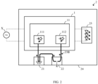
- FIG. 1 illustrates a luminaire 2 and a driver 1 in accordance with the present disclosure.
- the luminaire 2 includes the driver 1 and a light source 25 operable by the driver 1.
- the light source 25 may include an LED.
- the driver 1 may include an emergency lighting LED driver.
- the driver 1 includes a PCB 11 and a status indicator LED 111 preferably directly mounted on the PCB 11.
- the status indicator LED 111 may be arranged to emit visible light, and may additionally be arranged to emit invisible light.
- the driver 1 further includes an optical fiber arrangement 23A configured to deliver light emitted by the status indicator LED 111 at a light sensor 112 preferably directly mounted on the PCB 11 and connected to a control circuitry (not shown) of the driver 1.
- the light sensor 112 may include a photo diode.
- the optical fiber arrangement 23A may be configured to deliver light emitted by the status indicator LED 111 partly at a status indicator light output 21 spaced apart from the driver 1, and partly at the PCB-mounted light sensor 112 via a test button 22 spaced apart from the driver 1.
- the optical fiber arrangement 23A may include a 1x2 optic coupler, and may in particular include a 1x2 fused fiber optic coupler .
- the test button 22 may be arranged at a housing 24 of the luminaire 2 inside which the driver 1 is arranged, and may be arranged to selectively block incident light through actuation. As such, an actuation of the test button 22 will selectively block the light emitted by the status indicator LED 111 and partly delivered at the PCB-mounted light sensor 112 via the test button 22.
- the control circuitry of the driver 1 may be arranged to monitor a reception of the light sensor 112 for detecting the actuation of the test button 22.
- the status indicator light output 21 and the test button 22 may be integral with one another, i.e. may form an assembly.
- FIG. 2 illustrates a further luminaire 2 and driver 1 in accordance with the present disclosure.
- a 1x2 optic coupler may be included in the status indicator light output 21.
- the 1x2 optic coupler included in the status indicator light output 21 may be arranged to generate the light output through macro-bending.
- the fiber cable may be subjected to a significant amount of bending above a critical value of curvature. This inhibits the light guidance mechanism and causes light energy to be radiated from the fiber.
- the macro-bending may be accomplished in many ways, including leading the fiber around a member having a curvature or cylindric radius which is suitable of causing enough macro-bending losses for delivering light emitted by the status indicator LED 111 partly at the status indicator light output 21.
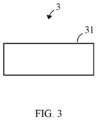
- FIG. 3 illustrates a flow chart of a method 3 in accordance with the present disclosure of operating a driver 1.
- the driver 1 includes a PCB 11 and a status indicator LED 111 preferably directly mounted on the PCB 11.
- the method 3 includes: using 31 an optical fiber arrangement 23A; 23B to deliver light emitted by the status indicator LED 111 at a light sensor 112, which is also preferably directly mounted on the PCB 11 and connected to a control circuitry of the driver 1.
Landscapes
- Circuit Arrangement For Electric Light Sources In General (AREA)
- Arrangement Of Elements, Cooling, Sealing, Or The Like Of Lighting Devices (AREA)
Abstract
Description
- The present disclosure relates to lighting technology, and to status indicator LEDs as well as test switches thereof. In particular, the present disclosure relates to a driver for a light source, a method of operating the same, and a luminaire including the driver.
- Emergency lighting systems are compulsory in many official buildings and workplaces so that people can find their way around safely in the unlikely event of a power failure.
- Emergency lighting drivers equipped for manually initiated testing may be provided with a status indicator LED and a test button. Long wire connections between such an assembly and the driver, for example in a meter range, can lead to problems with meeting EMC & transient standards as noise can be induced via the long leads. Avoiding these problems may complicate and/or impose limits on a design of the emergency lighting system.
- In view of the above-mentioned drawbacks and limitations, the present disclosure aims to improve the emergency lighting systems of the background art. An objective is to provide a lighting driver avoiding EMC & transient issues in connection with remote status indicator and test button assemblies.
- The objective is achieved by the embodiments as defined by the appended independent claims. Preferred embodiments are set forth in the dependent claims and in the following description and drawings.
- A first aspect of the present disclosure relates to a driver for a light source, including a printed circuit board (PCB); a status indicator LED preferably directly mounted on the PCB; and an optical fiber arrangement configured to deliver light emitted by the status indicator LED at a light sensor preferably directly mounted on the PCB and connected to a control circuitry of the driver.
- The optical fiber arrangement may be configured to deliver light emitted by the status indicator LED partly at a status indicator light output spaced apart from the driver, and partly at the PCB-mounted light sensor via a test button spaced apart from the driver. The test button may be arranged to selectively block incident light through actuation.
- The driver may include an emergency lighting LED driver; and the light source may include an LED.
- The LED may be arranged to emit visible light.
- The LED may be arranged to emit invisible light.
- The control circuitry may be arranged to monitor a reception of the light sensor for detecting the actuation of the test button.
- The optical fiber arrangement may include a 1x2 optic coupler.
- The optical fiber arrangement may include a 1x2 fused fiber optic coupler.
- The status indicator light output may include a 1x2 optic coupler.
- The 1x2 optic coupler may be arranged to generate the light output through macro-bending.
- The status indicator light output and the test button may be integral with one another.
- The light sensor may include a photo diode.
- A second aspect of the present disclosure relates to a luminaire, including a driver of the first aspect or any of its implementations; and a light source operable by the driver.
- The test button may be arranged at a housing of the luminaire inside which the driver is arranged.
- A third aspect of the present disclosure relates to a method of operating a driver for a light source. The driver includes a PCB and a status indicator LED preferably directly mounted on the PCB. The method includes: using an optical fiber arrangement to deliver light emitted by the status indicator LED at a light sensor preferably directly mounted on the PCB and connected to a control circuitry of the driver.
- The present disclosure proposes using a flexible fibre-optic cable and a PCB-mounted status indicator LED to replace leaded status indicator LEDs, and implementing the test button function using optical feedback from the indicator LED. Light guides have been seen on luminaires previously but they have been of the solid type, usually built into the construction of the luminaire itself.
- Fibre-optic cables are non-conductive and thus immune to problems with passing transient tests & meeting EMC standards.
- The flexible nature of optical fiber makes routing and positioning of the status indicator easier for the luminaire manufacturer when compared to solid light guides.
- Placing the status indicator LED on the driver PCB and using a flexible optical fibre to carry the light from the indicator through the luminaire to where ever needed by the luminaire design without picking up any noise may simplify a design and reduce development time for the both the driver designer and the luminaire manufacturer.
- The above-described aspects and implementations will now be explained with reference to the accompanying drawings, in which the same or similar reference numerals designate the same or similar elements.
- The features of these aspects and implementations may be combined with each other unless specifically stated otherwise.
- The drawings are to be regarded as being schematic representations, and elements illustrated in the drawings are not necessarily shown to scale. Rather, the various elements are represented such that their function and general purpose become apparent to those skilled in the art.
-
FIG. 1 illustrates a luminaire and a driver in accordance with the present disclosure; -
FIG. 2 illustrates a further luminaire and driver in accordance with the present disclosure; -
FIG. 3 illustrates a flow chart of a method in accordance with the present disclosure of operating a driver. -
FIG. 1 illustrates aluminaire 2 and a driver 1 in accordance with the present disclosure. - The
luminaire 2 includes the driver 1 and alight source 25 operable by the driver 1. Thelight source 25 may include an LED. - The driver 1 may include an emergency lighting LED driver. The driver 1 includes a PCB 11 and a
status indicator LED 111 preferably directly mounted on the PCB 11. Thestatus indicator LED 111 may be arranged to emit visible light, and may additionally be arranged to emit invisible light. - The driver 1 further includes an
optical fiber arrangement 23A configured to deliver light emitted by thestatus indicator LED 111 at alight sensor 112 preferably directly mounted on the PCB 11 and connected to a control circuitry (not shown) of the driver 1. Thelight sensor 112 may include a photo diode. - The
optical fiber arrangement 23A may be configured to deliver light emitted by thestatus indicator LED 111 partly at a statusindicator light output 21 spaced apart from the driver 1, and partly at the PCB-mountedlight sensor 112 via atest button 22 spaced apart from the driver 1. - To this end, the
optical fiber arrangement 23A may include a 1x2 optic coupler, and may in particular include a 1x2 fused fiber optic coupler . - The
test button 22 may be arranged at ahousing 24 of theluminaire 2 inside which the driver 1 is arranged, and may be arranged to selectively block incident light through actuation. As such, an actuation of thetest button 22 will selectively block the light emitted by thestatus indicator LED 111 and partly delivered at the PCB-mountedlight sensor 112 via thetest button 22. - The control circuitry of the driver 1 may be arranged to monitor a reception of the
light sensor 112 for detecting the actuation of thetest button 22. - The status
indicator light output 21 and thetest button 22 may be integral with one another, i.e. may form an assembly. -
FIG. 2 illustrates afurther luminaire 2 and driver 1 in accordance with the present disclosure. - In view of the degree of similarity of
FIGs. 1 and2 , similar items will not be described once again. - In the
optical fiber arrangement 23B ofFIG. 2 , a 1x2 optic coupler may be included in the statusindicator light output 21. - In particular, the 1x2 optic coupler included in the status
indicator light output 21 may be arranged to generate the light output through macro-bending. In other words, the fiber cable may be subjected to a significant amount of bending above a critical value of curvature. This inhibits the light guidance mechanism and causes light energy to be radiated from the fiber. - The macro-bending may be accomplished in many ways, including leading the fiber around a member having a curvature or cylindric radius which is suitable of causing enough macro-bending losses for delivering light emitted by the
status indicator LED 111 partly at the status indicatorlight output 21. -
FIG. 3 illustrates a flow chart of a method 3 in accordance with the present disclosure of operating a driver 1. - The driver 1 includes a PCB 11 and a
status indicator LED 111 preferably directly mounted on the PCB 11. - The method 3 includes: using 31 an
optical fiber arrangement 23A; 23B to deliver light emitted by thestatus indicator LED 111 at alight sensor 112, which is also preferably directly mounted on the PCB 11 and connected to a control circuitry of the driver 1. - Advantageously, the technical effects and advantages described above in relation with the driver 1 equally apply to the method 3 having corresponding features.
Claims (15)
- A driver (1) for a light source (25), includinga printed circuit board, PCB (11);a status indicator LED (111) preferably directly mounted on the PCB (11); andan optical fiber arrangement (23A; 23B) configured to deliver light emitted by the status indicator LED (111) at a light sensor (112) preferably directly mounted on the PCB (11) and connected to a control circuitry of the driver (1).
- The driver of claim 1,
the optical fiber arrangement (23A; 23B) configured to deliver light emitted by the status indicator LED (111)- partly at a status indicator light output (21) spaced apart from the driver (1), and- partly at the PCB-mounted light sensor (112) via a test button (22) spaced apart from the driver (1), the test button (22) arranged to selectively block incident light through actuation. - The driver of claim 1 or claim 2,the driver (1) including an emergency lighting LED driver; andthe light source (25) including an LED.
- The driver of any one of the preceding claims,
the status indicator LED (111) arranged to emit visible light. - The driver of any one of the preceding claims,
the LED status indicator (111) arranged to emit invisible light. - The driver (1) of any one of the preceding claims,
the control circuitry arranged to monitor a reception of the light sensor (112) for detecting the actuation of the test button (22). - The driver (1) of any one of the claims 1 to 6,
the optical fiber arrangement (23A) including a 1x2 optic coupler. - The driver (1) of claim 7,
the optical fiber arrangement (23A) including a 1x2 fused fiber optic coupler. - The driver (1) of any one of the claims 1 to 6,
the status indicator light output (21) including a 1x2 optic coupler. - The driver (1) of claim 9,
the 1x2 optic coupler arranged to generate the light output through macro-bending. - The driver (1) of any one of the preceding claims,
the status indicator light output (21) and the test button (22) being integral with one another. - The driver (1) of any one of the preceding claims,
the light sensor (112) including a photo diode. - A luminaire (2), includinga driver (1) of any one of the preceding claims; anda light source (25) operable by the driver (1).
- The luminaire (2) of claim 13,
the test button (22) arranged at a housing (24) of the luminaire (2) inside which the driver (1) is arranged. - A method (3) of operating a driver (1) for a light source (25),the driver (1) including a printed circuit board, PCB (11) and a status indicator LED (111) preferably directly mounted on the PCB (11);the method (3) includingusing (31) an optical fiber arrangement (23A; 23B) to deliver light emitted by the status indicator LED (111) at a light sensor (112) preferably directly mounted on the PCB (11) and connected to a control circuitry of the driver (1).
Priority Applications (2)
| Application Number | Priority Date | Filing Date | Title |
|---|---|---|---|
| EP21200649.8A EP4161216A1 (en) | 2021-10-04 | 2021-10-04 | Lighting driver with remote indicator led and emergency test button |
| PCT/EP2022/076063 WO2023057201A1 (en) | 2021-10-04 | 2022-09-20 | Lighting driver with remote indicator led and emergency test button |
Applications Claiming Priority (1)
| Application Number | Priority Date | Filing Date | Title |
|---|---|---|---|
| EP21200649.8A EP4161216A1 (en) | 2021-10-04 | 2021-10-04 | Lighting driver with remote indicator led and emergency test button |
Publications (1)
| Publication Number | Publication Date |
|---|---|
| EP4161216A1 true EP4161216A1 (en) | 2023-04-05 |
Family
ID=78078041
Family Applications (1)
| Application Number | Title | Priority Date | Filing Date |
|---|---|---|---|
| EP21200649.8A Pending EP4161216A1 (en) | 2021-10-04 | 2021-10-04 | Lighting driver with remote indicator led and emergency test button |
Country Status (2)
| Country | Link |
|---|---|
| EP (1) | EP4161216A1 (en) |
| WO (1) | WO2023057201A1 (en) |
Cited By (1)
| Publication number | Priority date | Publication date | Assignee | Title |
|---|---|---|---|---|
| EP4489525A1 (en) * | 2023-07-04 | 2025-01-08 | Tridonic GmbH & Co. KG | Status indication for emergency lighting equipment |
Citations (3)
| Publication number | Priority date | Publication date | Assignee | Title |
|---|---|---|---|---|
| JP2010071715A (en) * | 2008-09-17 | 2010-04-02 | Fuji Xerox Co Ltd | Testing machine for testing bending resistance of waveguide |
| US20120302874A1 (en) * | 2009-12-01 | 2012-11-29 | Hollstien David S | Non-invasive implant rupture detection system |
| US20180103303A1 (en) * | 2016-10-11 | 2018-04-12 | Fluke Corporation | Optically-addressable optical switch |
-
2021
- 2021-10-04 EP EP21200649.8A patent/EP4161216A1/en active Pending
-
2022
- 2022-09-20 WO PCT/EP2022/076063 patent/WO2023057201A1/en not_active Ceased
Patent Citations (3)
| Publication number | Priority date | Publication date | Assignee | Title |
|---|---|---|---|---|
| JP2010071715A (en) * | 2008-09-17 | 2010-04-02 | Fuji Xerox Co Ltd | Testing machine for testing bending resistance of waveguide |
| US20120302874A1 (en) * | 2009-12-01 | 2012-11-29 | Hollstien David S | Non-invasive implant rupture detection system |
| US20180103303A1 (en) * | 2016-10-11 | 2018-04-12 | Fluke Corporation | Optically-addressable optical switch |
Cited By (1)
| Publication number | Priority date | Publication date | Assignee | Title |
|---|---|---|---|---|
| EP4489525A1 (en) * | 2023-07-04 | 2025-01-08 | Tridonic GmbH & Co. KG | Status indication for emergency lighting equipment |
Also Published As
| Publication number | Publication date |
|---|---|
| WO2023057201A1 (en) | 2023-04-13 |
Similar Documents
| Publication | Publication Date | Title |
|---|---|---|
| RU2475905C2 (en) | Identifiable cable | |
| CA2957172C (en) | Optically interfaced remote data concentrator | |
| WO2023057201A1 (en) | Lighting driver with remote indicator led and emergency test button | |
| AU636395B2 (en) | Remote end detection | |
| EP3936755A1 (en) | Light module and mobile terminal | |
| JP5755853B2 (en) | Liquid detector and liquid identification system | |
| US20130223092A1 (en) | Aviation obstruction lighting | |
| US7512300B2 (en) | Compound optical and electrical conductors, and connectors therefor | |
| JP2013024738A (en) | Live-wire detection device | |
| US11527338B2 (en) | Patch cord inspecting system | |
| TW201418812A (en) | Optical coupler with light guide | |
| US7002453B2 (en) | Remote lamp status display via fiber optic system | |
| CN209401645U (en) | Back incident-type array photoelectric chip and its electric connection structure | |
| US7660497B2 (en) | Apparatus for transmitting optical signals between components which can be rotated relative to one another (rotary transmitter) | |
| US7015458B2 (en) | High density fiber optic output interface and system | |
| US11909146B2 (en) | Single Pair Ethernet connector | |
| US7380641B2 (en) | Elevator with a control using optical fibers | |
| CN221304044U (en) | Outdoor power supply prompting device | |
| CN219038819U (en) | Photoelectric sensor for detecting front and back surfaces of glass slide | |
| KR102004529B1 (en) | System for optic patch code measurement comprised optic fiber tap device for optic signal monitoring | |
| JP2001024590A (en) | Optical transmission line monitoring device | |
| CN115066580B (en) | Combined emergency wireless reporting antenna and indicator LED | |
| KR100707264B1 (en) | Optical module | |
| CN102193586A (en) | Electronic device | |
| JP2009545108A (en) | Illumination system with a light receiver for controlling an electronic ballast |
Legal Events
| Date | Code | Title | Description |
|---|---|---|---|
| PUAI | Public reference made under article 153(3) epc to a published international application that has entered the european phase |
Free format text: ORIGINAL CODE: 0009012 |
|
| STAA | Information on the status of an ep patent application or granted ep patent |
Free format text: STATUS: THE APPLICATION HAS BEEN PUBLISHED |
|
| AK | Designated contracting states |
Kind code of ref document: A1 Designated state(s): AL AT BE BG CH CY CZ DE DK EE ES FI FR GB GR HR HU IE IS IT LI LT LU LV MC MK MT NL NO PL PT RO RS SE SI SK SM TR |
|
| STAA | Information on the status of an ep patent application or granted ep patent |
Free format text: STATUS: REQUEST FOR EXAMINATION WAS MADE |
|
| 17P | Request for examination filed |
Effective date: 20230906 |
|
| RBV | Designated contracting states (corrected) |
Designated state(s): AL AT BE BG CH CY CZ DE DK EE ES FI FR GB GR HR HU IE IS IT LI LT LU LV MC MK MT NL NO PL PT RO RS SE SI SK SM TR |
|
| STAA | Information on the status of an ep patent application or granted ep patent |
Free format text: STATUS: EXAMINATION IS IN PROGRESS |
|
| 17Q | First examination report despatched |
Effective date: 20250117 |
|
| GRAP | Despatch of communication of intention to grant a patent |
Free format text: ORIGINAL CODE: EPIDOSNIGR1 |
|
| STAA | Information on the status of an ep patent application or granted ep patent |
Free format text: STATUS: GRANT OF PATENT IS INTENDED |
|
| INTG | Intention to grant announced |
Effective date: 20260407 |