EP4161209A1 - Method and apparatus for ue location report in a wireless communication system - Google Patents
Method and apparatus for ue location report in a wireless communication system Download PDFInfo
- Publication number
- EP4161209A1 EP4161209A1 EP22196666.6A EP22196666A EP4161209A1 EP 4161209 A1 EP4161209 A1 EP 4161209A1 EP 22196666 A EP22196666 A EP 22196666A EP 4161209 A1 EP4161209 A1 EP 4161209A1
- Authority
- EP
- European Patent Office
- Prior art keywords
- measurement
- report
- location
- cell
- information
- Prior art date
- Legal status (The legal status is an assumption and is not a legal conclusion. Google has not performed a legal analysis and makes no representation as to the accuracy of the status listed.)
- Granted
Links
Images





Classifications
-
- H—ELECTRICITY
- H04—ELECTRIC COMMUNICATION TECHNIQUE
- H04W—WIRELESS COMMUNICATION NETWORKS
- H04W64/00—Locating users or terminals or network equipment for network management purposes, e.g. mobility management
-
- G—PHYSICS
- G01—MEASURING; TESTING
- G01S—RADIO DIRECTION-FINDING; RADIO NAVIGATION; DETERMINING DISTANCE OR VELOCITY BY USE OF RADIO WAVES; LOCATING OR PRESENCE-DETECTING BY USE OF THE REFLECTION OR RERADIATION OF RADIO WAVES; ANALOGOUS ARRANGEMENTS USING OTHER WAVES
- G01S5/00—Position-fixing by co-ordinating two or more direction or position line determinations; Position-fixing by co-ordinating two or more distance determinations
- G01S5/0009—Transmission of position information to remote stations
- G01S5/0045—Transmission from base station to mobile station
- G01S5/0063—Transmission from base station to mobile station of measured values, i.e. measurement on base station and position calculation on mobile
-
- H—ELECTRICITY
- H04—ELECTRIC COMMUNICATION TECHNIQUE
- H04W—WIRELESS COMMUNICATION NETWORKS
- H04W24/00—Supervisory, monitoring or testing arrangements
- H04W24/08—Testing, supervising or monitoring using real traffic
-
- H—ELECTRICITY
- H04—ELECTRIC COMMUNICATION TECHNIQUE
- H04W—WIRELESS COMMUNICATION NETWORKS
- H04W24/00—Supervisory, monitoring or testing arrangements
- H04W24/10—Scheduling measurement reports ; Arrangements for measurement reports
-
- H—ELECTRICITY
- H04—ELECTRIC COMMUNICATION TECHNIQUE
- H04W—WIRELESS COMMUNICATION NETWORKS
- H04W36/00—Hand-off or reselection arrangements
- H04W36/0005—Control or signalling for completing the hand-off
- H04W36/0083—Determination of parameters used for hand-off, e.g. generation or modification of neighbour cell lists
- H04W36/0085—Hand-off measurements
- H04W36/0088—Scheduling hand-off measurements
-
- H—ELECTRICITY
- H04—ELECTRIC COMMUNICATION TECHNIQUE
- H04W—WIRELESS COMMUNICATION NETWORKS
- H04W84/00—Network topologies
- H04W84/02—Hierarchically pre-organised networks, e.g. paging networks, cellular networks, WLAN [Wireless Local Area Network] or WLL [Wireless Local Loop]
- H04W84/04—Large scale networks; Deep hierarchical networks
- H04W84/06—Airborne or Satellite Networks
Definitions
- This disclosure generally relates to wireless communication networks and, more particularly, to a method and apparatus for User Equipment (UE) location reporting in a wireless communication system to facilitate efficiency in location information reporting in Non-Terrestrial Networks (NTNs).
- UE User Equipment
- IP Internet Protocol
- An exemplary network structure is an Evolved Universal Terrestrial Radio Access Network (E-UTRAN).
- E-UTRAN Evolved Universal Terrestrial Radio Access Network
- the E-UTRAN system can provide high data throughput in order to realize the above-noted voice over IP and multimedia services.
- a new radio technology for the next generation e.g., 5G
- 5G next generation
- changes to the current body of 3GPP standard are currently being submitted and considered to evolve and finalize the 3GPP standard.
- UE User Equipment
- NTNs Non-Terrestrial Networks
- a method for a UE in a wireless communication system comprises receiving a first configuration to trigger measurement reporting based on a first event that distance between the UE and a first reference location of a serving cell becomes larger than a distance threshold and distance between the UE and a second reference location of a first neighbor cell becomes shorter than another distance threshold, and triggering a first measurement report based on the first event, wherein measured radio condition of the first neighbor cell is omitted or not included in the first measurement report.
- the invention described herein can be applied to or implemented in exemplary wireless communication systems and devices described below.
- the invention is described mainly in the context of the 3GPP architecture reference model. However, it is understood that with the disclosed information, one skilled in the art could easily adapt for use and implement aspects of the invention in a 3GPP2 network architecture as well as in other network architectures.
- Wireless communication systems are widely deployed to provide various types of communication such as voice, data, and so on. These systems may be based on code division multiple access (CDMA), time division multiple access (TDMA), orthogonal frequency division multiple access (OFDMA), 3GPP LTE (Long Term Evolution) wireless access, 3GPP LTE-A (Long Term Evolution Advanced) wireless access, 3GPP2 UMB (Ultra Mobile Broadband), WiMax, 3GPP NR (New Radio), or some other modulation techniques.
- CDMA code division multiple access
- TDMA time division multiple access
- OFDMA orthogonal frequency division multiple access
- 3GPP LTE Long Term Evolution
- 3GPP LTE-A Long Term Evolution Advanced wireless access
- 3GPP2 UMB Universal Mobile Broadband
- WiMax Wireless Broadband
- 3GPP NR New Radio
- the exemplary wireless communication systems and devices described below may be designed to support one or more standards such as the standard offered by a consortium named "3rd Generation Partnership Project” referred to herein as 3GPP, including: [1] RP-201256, “Solutions for NR to support non-terrestrial networks (NTN) "; [2] 3GPP TS 38.331 V16.5.0, “NR, RRC protocol specification "; [3] R2-2111614, “Stage-3 running RRC CR for NTN Rel-17 “; [4] RP-211774, “Status Report to TSG “; [5] 3GPP TR 38.821 V16.0.0, “Solutions for NR to support non-terrestrial networks (NTN) "; [6] R2-2011041, "Reply LS on SA WG2 assumptions from conclusion of study on architecture aspects for using satellite access in 5G "; [7] R2-2111221, “LS on UE TA reporting "; [8] R2-2111333, "
- FIG. 1 shows a multiple access wireless communication system according to one embodiment of the invention.
- An access network 100 includes multiple antenna groups, one including 104 and 106, another including 108 and 110, and an additional including 112 and 114. In FIG. 1 , only two antennas are shown for each antenna group, however, more or fewer antennas may be utilized for each antenna group.
- Access terminal (AT) 116 is in communication with antennas 112 and 114, where antennas 112 and 114 transmit information to access terminal 116 over forward link 120 and receive information from AT 116 over reverse link 118.
- AT 122 is in communication with antennas 106 and 108, where antennas 106 and 108 transmit information to AT 122 over forward link 126 and receive information from AT 122 over reverse link 124.
- communication links 118, 120, 124 and 126 may use different frequency for communication. For example, forward link 120 may use a different frequency than that used by reverse link 118.
- antenna groups each are designed to communicate to access terminals in a sector of the areas covered by access network 100.
- the transmitting antennas of access network 100 may utilize beamforming in order to improve the signal-to-noise ratio of forward links for the different access terminals 116 and 122. Also, an access network using beamforming to transmit to access terminals scattered randomly through its coverage normally causes less interference to access terminals in neighboring cells than an access network transmitting through a single antenna to all its access terminals.
- the AN may be a fixed station or base station used for communicating with the terminals and may also be referred to as an access point, a Node B, a base station, an enhanced base station, an eNodeB, or some other terminology.
- the AT may also be called User Equipment (UE), a wireless communication device, terminal, access terminal or some other terminology.
- UE User Equipment
- FIG. 2 is a simplified block diagram of an embodiment of a transmitter system 210 (also known as the access network) and a receiver system 250 (also known as access terminal (AT) or user equipment (UE)) in a MIMO system 200.
- a transmitter system 210 also known as the access network
- a receiver system 250 also known as access terminal (AT) or user equipment (UE)
- traffic data for a number of data streams is provided from a data source 212 to a transmit (TX) data processor 214.
- TX transmit
- each data stream is transmitted over a respective transmit antenna.
- TX data processor 214 formats, codes, and interleaves the traffic data for each data stream based on a particular coding scheme selected for that data stream to provide coded data.
- the coded data for each data stream may be multiplexed with pilot data using OFDM techniques.
- the pilot data is typically a known data pattern that is processed in a known manner and may be used at the receiver system to estimate the channel response.
- the multiplexed pilot and coded data for each data stream is then modulated (e.g., symbol mapped) based on a particular modulation scheme (e.g., BPSK, QPSK, M-PSK, or M-QAM) selected for that data stream to provide modulation symbols.
- the data rate, coding, and modulation for each data stream may be determined by instructions performed by processor 230.
- a memory 232 is coupled to processor 230.
- TX MIMO processor 220 may further process the modulation symbols (e.g., for OFDM).
- TX MIMO processor 220 then provides N T modulation symbol streams to N T transmitters (TMTR) 222a through 222t.
- TMTR TX MIMO processor 220 applies beamforming weights to the symbols of the data streams and to the antenna from which the symbol is being transmitted.
- Each transmitter 222 receives and processes a respective symbol stream to provide one or more analog signals, and further conditions (e.g., amplifies, filters, and upconverts) the analog signals to provide a modulated signal suitable for transmission over the MIMO channel.
- N T modulated signals from transmitters 222a through 222t are then transmitted from N T antennas 224a through 224t, respectively.
- the transmitted modulated signals are received by N R antennas 252a through 252r and the received signal from each antenna 252 is provided to a respective receiver (RCVR) 254a through 254r.
- Each receiver 254 conditions (e.g., filters, amplifies, and downconverts) a respective received signal, digitizes the conditioned signal to provide samples, and further processes the samples to provide a corresponding "received" symbol stream.
- An RX data processor 260 then receives and processes the N R received symbol streams from N R receivers 254 based on a particular receiver processing technique to provide N T "detected" symbol streams.
- the RX data processor 260 then demodulates, deinterleaves, and decodes each detected symbol stream to recover the traffic data for the data stream.
- the processing by RX data processor 260 is complementary to that performed by TX MIMO processor 220 and TX data processor 214 at transmitter system 210.
- a processor 270 periodically determines which pre-coding matrix to use (discussed below). Processor 270 formulates a reverse link message comprising a matrix index portion and a rank value portion.
- the reverse link message may comprise various types of information regarding the communication link and/or the received data stream.
- the reverse link message is then processed by a TX data processor 238, which also receives traffic data for a number of data streams from a data source 236, modulated by a modulator 280, conditioned by transmitters 254a through 254r, and transmitted back to transmitter system 210.
- the modulated signals from receiver system 250 are received by antennas 224, conditioned by receivers 222, demodulated by a demodulator 240, and processed by a RX data processor 242 to extract the reserve link message transmitted by the receiver system 250.
- Processor 230 determines which pre-coding matrix to use for determining the beamforming weights then processes the extracted message.
- Memory 232 may be used to temporarily store some buffered/computational data from 240 or 242 through Processor 230, store some buffed data from 212, or store some specific program codes.
- Memory 272 may be used to temporarily store some buffered/computational data from 260 through Processor 270, store some buffed data from 236, or store some specific program codes.
- FIG. 3 shows an alternative simplified functional block diagram of a communication device according to one embodiment of the invention.
- the communication device 300 in a wireless communication system can be utilized for realizing the UEs (or ATs) 116 and 122 in FIG. 1 , and the wireless communications system is preferably the NR system.
- the communication device 300 may include an input device 302, an output device 304, a control circuit 306, a central processing unit (CPU) 308, a memory 310, a program code 312, and a transceiver 314.
- the control circuit 306 executes the program code 312 in the memory 310 through the CPU 308, thereby controlling an operation of the communications device 300.
- the communications device 300 can receive signals input by a user through the input device 302, such as a keyboard or keypad, and can output images and sounds through the output device 304, such as a monitor or speakers.
- the transceiver 314 is used to receive and transmit wireless signals, delivering received signals to the control circuit 306, and outputting signals generated by the control circuit 306 wirelessly.
- FIG. 4 is a simplified block diagram of the program code 312 shown in FIG. 3 in accordance with an embodiment of the invention.
- the program code 312 includes an application layer 400, a Layer 3 portion 402, and a Layer 2 portion 404, and is coupled to a Layer 1 portion 406.
- the Layer 3 portion 402 generally performs radio resource control.
- the Layer 2 portion 404 generally performs link control.
- the Layer 1 portion 406 generally performs physical connections.
- the Layer 2 portion 404 may include a Radio Link Control (RLC) layer and a Medium Access Control (MAC) layer.
- the Layer 3 portion 402 may include a Radio Resource Control (RRC) layer.
- NTN non-terrestrial networks
- the network may configure an RRC_CONNECTED UE to perform measurements.
- the network may configure the UE to report them in accordance with the measurement configuration or perform conditional reconfiguration evaluation in accordance with the conditional reconfiguration.
- the measurement configuration is provided by means of dedicated signalling i.e. using the RRCReconfiguration or RRCResume.
- the network may configure the UE to perform the following types of measurements:
- the network may configure the UE to report the following measurement information based on SS/PBCH block(s):
- the network may configure the UE to report the following measurement information based on CSI-RS resources:
- each configuration consists of the following:
- Measurement identities For measurement reporting, a list of measurement identities where each measurement identity links one measurement object with one reporting configuration. By configuring multiple measurement identities, it is possible to link more than one measurement object to the same reporting configuration, as well as to link more than one reporting configuration to the same measurement object.
- the measurement identity is also included in the measurement report that triggered the reporting, serving as a reference to the network.
- conditional reconfiguration triggering one measurement identity links to exactly one conditional reconfiguration trigger configuration. And up to 2 measurement identities can be linked to one conditional reconfiguration execution condition.
- Quantity configurations The quantity configuration defines the measurement filtering configuration used for all event evaluation and related reporting, and for periodical reporting of that measurement.
- the network may configure up to 2 quantity configurations with a reference in the NR measurement object to the configuration that is to be used. In each configuration, different filter coefficients can be configured for different measurement quantities, for different RS types, and for measurements per cell and per beam.
- Measurement gaps Periods that the UE may use to perform measurements.
- a UE in RRC_CONNECTED maintains a measurement object list, a reporting configuration list, and a measurement identities list according to signalling and procedures in this specification.
- the measurement object list possibly includes NR measurement object(s), CLI measurement object(s) and inter-RAT objects.
- the reporting configuration list includes NR and inter-RAT reporting configurations. Any measurement object can be linked to any reporting configuration of the same RAT type. Some reporting configurations may not be linked to a measurement object. Likewise, some measurement objects may not be linked to a reporting configuration.
- the measurement procedures distinguish the following types of cells:
- the UE measures and reports on the serving cell(s), listed cells and/or detected cells.
- the UE measures and reports on listed cells and detected cells and, for RSSI and channel occupancy measurements, the UE measures and reports on the configured resources on the indicated frequency.
- the UE measures and reports on listed cells.
- the UE measures and reports on configured measurement resources (i.e. SRS resources and/or CLI-RSSI resources).
- An RRC_CONNECTED UE shall derive cell measurement results by measuring one or multiple beams associated per cell as configured by the network, as described in 5.5.3.3. For all cell measurement results, except for RSSI, and CLI measurement results in RRC_CONNECTED, the UE applies the layer 3 filtering as specified in 5.5.3.2, before using the measured results for evaluation of reporting criteria, measurement reporting or the criteria to trigger conditional reconfiguration execution.
- the network can configure RSRP, RSRQ, SINR, RSCP or EcN0 as trigger quantity.
- SINR SINR
- RSCP RSCP
- EcN0 the network can configure SRS-RSRP or CLI-RSSI as trigger quantity.
- reporting quantities can be any combination of quantities (i.e.
- reporting quantities can be either SRS-RSRP or CLI-RSSI.
- the network can configure up to 2 quantities, both using same RS type. The UE does not apply the layer 3 filtering as specified in 5.5.3.2 to derive the CBR measurements.
- the network may also configure the UE to report measurement information per beam (which can either be measurement results per beam with respective beam identifier(s) or only beam identifier(s)), derived as described in 5.5.3.3a. If beam measurement information is configured to be included in measurement reports, the UE applies the layer 3 beam filtering as specified in 5.5.3.2. On the other hand, the exact L1 filtering of beam measurements used to derive cell measurement results is implementation dependent.
- the UE shall:
- the UE shall:
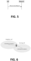
- FIG. 5 is a reproduction of Figure 5.5.5.1-1: Measurement reporting, from 3GPP TS 38.331 V16.5.0, "NR, RRC protocol specification. "
- This procedure is to transfer measurement results from the UE to the network.
- the UE shall initiate this procedure only after successful AS security activation.
- the UE shall set the measResults within the MeasurementReport message as follows:
- the UE For beam measurement information to be included in a measurement report the UE shall:
- the IE CommonLocationInfo is used to transfer detailed location information available at the UE to correlate measurements and UE position information.
- the first/leftmost bit of the first octet contains the most significant bit.
- locationTimeStamp Parameter type DisplacementTimeStamp defined in TS 37.355 [49].
- the first/leftmost bit of the first octet contains the most significant bit.
- locationCoordinate Parameter type LocationCoordinates defined in TS 37.355 [49].
- the first/leftmost bit of the first octet contains the most significant bit.
- locationError Parameter LocationError defined in TS 37.355 [49].
- the first/leftmost bit of the first octet contains the most significant bit.
- the first/leftmost bit of the first octet contains the most significant bit.
- velocityEstimate Parameter type Velocity defined in TS 37.355 [49].
- the first/leftmost bit of the first octet contains the most significant bit.
- the IE Loc ⁇ tionInfo is used to transfer available detailed location information, Bluetooth, WLAN and sensor available measurement results at the UE.
- the IE MeasConfig specifies measurements to be performed by the UE, and covers intra-frequency, inter-frequency and inter-RAT mobility as well as configuration of measurement gaps.
- MeasConfig field descriptions interFrequencyConfig-NoGap-r16 If the field is set to true, UE is configured to perform SSB based inter-frequency measurement without measurement gaps when the inter-frequency SSB is completely contained in the active DL BWP of the UE, as specified in TS 38.133 [14], clause 9.3. Otherwise, the SSB based inter-frequency measurement is performed within measurement gaps.
- measGapConfig Used to setup and release measurement gaps in NR.
- measIdToAddModList List of measurement identities to add and/or modify.
- measIdToRemoveList List of measurement identities to remove.
- measObjectToAddModList List of measurement objects to add and/or modify.
- s-MeasureConfig Threshold for NR SpCell RSRP measurement controlling when the UE is required to perform measurements on non-serving cells.
- Choice of ssb-RSRP corresponds to cell RSRP based on SS/PBCH block and choice of csi-RSRP corresponds to cell RSRP of CSI-RS.
- the IE MeasId is used to identify a measurement configuration, i.e., linking of a measurement object and a reporting configuration.
- the IE MeasResults covers measured results for intra-frequency, inter-frequency, inter-RAT mobility and measured results for sidelink.
- Section MeasResults field descriptions me ⁇ sId Identifies the measurement identity for which the reporting is being performed.
- measQuantityResults The value sinr is not included when it is used for LogMeasReport-r16.
- measResultForRSSI Includes measured RSSI result in dBm (see TS 38.215 [9]) and channelOccupancy which is the percentage of samples when the RSSI was above the configured channelOccupancyThreshold for the associated reportConfig.
- measResultServingMOList Measured results of measured cells with reference signals indicated in the serving cell measurement objects including measurement results of SpCell, configured SCell(s) and best neighbouring cell within measured cells with reference signals indicated in on each serving cell measurement object. If the sending of the MeasurementReport message is triggered by a measurement configured by the field sl-ConfigDedicatedForNR received within an E-UTRA RRCConnectionReconfiguration message (i.e. CBR measurements), this field is not applicable and its contents is ignored by the network.
- the IE ReportConfigNR specifies criteria for triggering of an NR measurement reporting event or of a CHO or CPC event. For events labelled AN with N equal to 1, 2 and so on, measurement reporting events and CHO or CPC events are based on cell measurement results, which can either be derived based on SS/PBCH block or CSI-RS.
- measurement reporting event is based on CLI measurement results, which can either be derived based on SRS-RSRP or CLI-RSSI.
- Event I1 Interference becomes higher than absolute threshold.
- ReportConfigNR field descriptions reportType Type of the configured measurement report In MR-DC, network does not configure report of type reportCGI using SRB3.
- the condTriggerConfig is used for CHO or CPC configuration.
- Table EventTriggerConfig field descriptions a3-Offset / a6-Offset Offset value(s) to be used in NR measurement report triggering condition for event a3/a6.
- the actual value is field value * 0.5 dB.
- the thresholds are differentiated by M.
- the network configures aN-Threshold1 only for events A1, A2, A4, A5 and a5-Threshold2 only for event A5.
- the network configures the same quantity for the MeasTriggerQuantity of the a5-Threshold1 and for the MeasTriggerQuantity of the a5-Threshold2.
- channelOccupancyThreshold RSSI threshold which is used for channel occupancy evaluation. eventId Choice of NR event triggered reporting criteria. maxNrofRS-IndexesToReport Max number of RS indexes to include in the measurement report for A1-A6 events.
- maxReportCells Max number of non-serving cells to include in the measurement report.
- reportAddNeighMeas Indicates that the UE shall include the best neighbour cells per serving frequency.
- reportAmount Number of measurement reports applicable for eventTriggered as well as for periodical report types.
- reportOnLeave Indicates whether or not the UE shall initiate the measurement reporting procedure when the leaving condition is met for a cell in cellsTriggeredList, as specified in 5.5.4.1.
- reportQuantityCell The cell measurement quantities to be included in the measurement report.
- reportQuantityRS-Indexes Indicates which measurement information per RS index the UE shall include in the measurement report. time To Trigger Time during which specific criteria for the event needs to be met in order to trigger a measurement report.
- UseT312 If value TRUE is configured, the UE shall use the timer T312 with the value t312 as specified in the corresponding measObjectNR. If value FALSE is configured, the timer T312 is considered as disabled. Network configures value TRUE only if reportType is set to eventTriggered. use White CellList Indicates whether only the cells included in the white-list of the associated measObject are applicable as specified in 5.5.4.1.
- the UE shall perform the actual UL PDCP Packet Average Delay measurement per DRB as specified in TS 38.314 [53] and the UE shall ignore the fields reportQuantityCell and maxReportCells.
- the applicable values for the corresponding reportInterval are (one of the) ⁇ ms120, ms240, ms480, ms640, ms1024, ms2048, ms5120, ms10240, ms20480, ms40960, min1,min6, min12, min30 ⁇ .
- the reportInterval indicates the periodicity for performing and reporting of UL PDCP Packet Average Delay per DRB measurement as specified in TS 38.314 [53].
- Use White CellList Indicates whether only the cells included in the white-list of the associated measObject are applicable as specified in 5.5.4.1.
- the IE ReportConfigToAddModList concerns a list of reporting configurations to add or modify.
- the NTN status report including agreements from 3GPP RAN2 #115 meeting is quoted as below from [4] RP-211774, "Status Report to TSG ":
- the network can configure the UE to send either the UE specific TA pre-compensation (for the details of the TA value, confirmation from RAN1 is needed) or the UE location information
- gNB can obtain a GNSS-based location information from the UE using existing signalling method, i.e., by configuring includeCommonLocationInfo in the corresponding reportConfig. It is up to SA3 to decide whether User Consent is required before NW acquires location information from the UE in NTN. RAN2 discuss whether to send LS to SA3
- Aperiodic location reporting (e.g., via DCI) is not supported.
- Event triggered-based UE location reporting are configured by gNB to obtain UE location update of mobile UEs in RRC_CONNECTED
- the measurement report, SMTC and some related configurations are specified in [2] 3GPP TS 38.331 V16.5.0, "NR, RRC protocol specification " with a NTN running CR, e.g., [3] R2-2111614, “Stage-3 running RRC CR for NTN Rel-17” as below:
- the UE shall setup the first SS/PBCH block measurement timing configuration (SMTC) in accordance with the received periodicityAndOffset parameter (providing Periodicity and Offset value for the following condition) in the smtc1 configuration.
- SMTC SS/PBCH block measurement timing configuration
- the first subframe of each SMTC occasion occurs at an SFN and subframe of the NR SpCell meeting the following condition:
- the UE shall setup an additional SS/PBCH block measurement timing configuration (SMTC) in accordance with the received periodicity parameter in the smtc2 configuration and use the Offset (derived from parameter periodicityAndOffset ) and duration parameter from the smtc1 configuration.
- SMTC SS/PBCH block measurement timing configuration
- the first subframe of each SMTC occasion occurs at an SFN and subframe of the NR SpCell meeting the above condition.
- the UE shall setup an additional SS/PBCH block measurement timing configuration (SMTC) in accordance with the received periodicity parameter in the smtc2-LP configuration and use the Offset (derived from parameter periodicityAndOffset ) and duration parameter from the smtc configuration for that frequency.
- SMTC SS/PBCH block measurement timing configuration
- the first subframe of each SMTC occasion occurs at an SFN and subframe of the NR SpCell or serving cell (for cell reselection) meeting the above condition.
- the IAB-MT shall setup an additional SS block measurement timing configuration in accordance with the received periodicityAndOffset parameter (using same condition as smtc1 to identify the SFN and the subframe for SMTC occasion) in each SSB-MTC3 configuration and use the duration and ssb-ToMeasure parameters from each SSB-MTC3 configuration.
- the UE shall not consider SS/PBCH block transmission in subframes outside the SMTC occasion for RRM measurements based on SS/PBCH blocks and for RRM measurements based on CSI-RS except for SFTD measurement (see TS 38.133 [14], subclause 9.3.8).
- the IE Me ⁇ sObjectNR specifies information applicable for SS/PBCH block(s) intra/inter-frequency measurements and/or CSI-RS intra/inter-frequency measurements.
- CellsToAddMod field descriptions celllndividualOffset Cell individual offsets applicable to a specific cell.
- physCellld Physical cell identity of a cell in the cell list.
- MeasObjectNR field descriptions absThreshCSI-RS-Consolidation Absolute threshold for the consolidation of measurement results per CSI-RS resource(s) from L1 filter(s). The field is used for the derivation of cell measurement results as described in 5.5.3.3 and the reporting of beam measurement information per CSI-RS resource as described in 5.5.5.2.
- blackCellsToAddModList List of cells to add/modify in the black list of cells. It applies only to SSB resources. blackCellsToRemoveList List of cells to remove from the black list of cells. cellsToAddModList List of cells to add/modify in the cell list. cellsToRemoveList List of cells to remove from the cell list. freqBandIndicatorNR The frequency band in which the SSB and/or CSI-RS indicated in this MeasObjectNR are located and according to which the UE shall perform the RRM measurements.
- meas CycleS Cell The parameter is used only when an SCell is configured on the frequency indicated by the measObjectNR and is in deactivated state, see TS 38.133 [14].
- gNB configures the parameter whenever an SCell is configured on the frequency indicated by the measObjectNR, but the field may also be signalled when an SCell is not configured.
- Value sf160 corresponds to 160 sub-frames
- value sf256 corresponds to 256 sub-frames and so on.
- nrofCSInrofCSI-RS-ResourcesToAverage Indicates the maximum number of measurement results per beam based on CSI-RS resources to be averaged.
- nrofSS-BlocksToAverage Indicates the maximum number of measurement results per beam based on SS/PBCH blocks to be averaged. The same value applies for each detected cell associated with this MeasObject.
- quantityConfigIndex Indicates the n -th element of quantityConfigNR-List provided in MeasConfig. referenceSignalConfig RS configuration for SS/PBCH block and CSI-RS.
- refFreqCSI-RS Point A which is used for mapping of CSI-RS to physical resources according to TS 38.211 [16] clause 7.4.1.5.3.
- smtc1 Primary measurement timing configuration (see clause 5.5.2.10).
- the periodicity is indicated by periodicity in smtc2 and the timing offset is equal to the offset indicated in periodicityAndOffset modulo periodicity.
- periodicity in smtc2 can only be set to a value strictly shorter than the periodicity indicated by periodicityAndOffset in smtc1 (e.g. if periodicityAndOffset indicates sf10, periodicity can only be set of sf5 , if periodicityAndOffset indicates sf5 , smtc2 cannot be configured).
- ssb-PositionQCL-Common Indicates the QCL relationship between SS/PBCH blocks for all measured cells as specified in TS 38.213 [13], clause 4.1. ssbSubcarrierSpacing Subcarrier spacing of SSB.
- t312 The value of timer T312. Value ms0 represents 0 ms, ms50 represents 50 ms and so on.
- Table SSB-ConfigMobility field descriptions deriveSSB-IndexFromCell If this field is set to true, UE assumes SFN and frame boundary alignment across cells on the same frequency carrier as specified in TS 38.133 [14].
- this field indicates whether the UE can utilize the timing of this serving cell to derive the index of SS block transmitted by neighbour cell. Otherwise, this field indicates whether the UE may use the timing of any detected cell on that target frequency to derive the SSB index of all neighbour cells on that frequency. ssb-ToMeasure The set of SS blocks to be measured within the SMTC measurement duration.
- the first/leftmost bit corresponds to SS/PBCH block index 0, the second bit corresponds to SS/PBCH block index 1, and so on.
- Value 0 in the bitmap indicates that the corresponding SS/PBCH block is not to be measured while value 1 indicates that the corresponding SS/PBCH block is to be measured (see TS 38.215 [9]).
- the UE measures on all SS blocks. Regardless of the value of this field, SS/PBCH blocks outside of the applicable smtc are not to be measured. See TS 38.215 [9] clause 5.1.1.
- This field is mandatory present if csi-rs-ResourceConfigMobility is configured, otherwise, it is absent.
- SSBorAssociatedSSB This field is mandatory present if ssb-ConfigMobility is configured or associatedSSB is configured in at least one cell. Otherwise, it is absent, Need R.
- IntraFreqConnected This field is optionally present, Need R if the UE is configured with a serving cell for which (absoluteFrequencySSB, subcarrierSpacing) in ServingCellConfigCommon is equal to ( ssbFrequency , ssbSubcarrierSpacing ) in this MeasObjectNR, otherwise, it is absent.
- SharedSpectrum This field is mandatory present if this MeasObject is for a frequency which operates with shared spectrum channel access. Otherwise, it is absent, Need R.
- the IE ReportConfigNR specifies criteria for triggering of an NR measurement reporting event or of a CHO or CPC event. For events labelled AN with N equal to 1, 2 and so on, measurement reporting events and CHO or CPC events are based on cell measurement results, which can either be derived based on SS/PBCH block or CSI-RS.
- measurement reporting event is based on CLI measurement results, which can either be derived based on SRS-RSRP or CLI-RSSI.
- Event I1 Interference becomes higher than absolute threshold.
- CondTriggerConfig field descriptions a3-Offset Offset value(s) to be used in NR conditional reconfiguration triggering condition for cond event a3.
- the actual value is field value * 0.5 dB.
- the selected trigger quantity e.g. RSRP, RSRQ, SINR
- RS Type e.g. SS/PBCH block, CSI-RS
- the network configures the same quantity for the MeasTriggerQuantity of the a5-Threshold1 and for the MeasTriggerQuantity of the a5-Threshold2.
- condEventId Choice of NR conditional reconfiguration event triggered criteria referenceLocation1 , referenceLocation2 Reference locations used for location based event. The referenceLocation1 is associated to serving cell and referenceLocation2 is associated to candidate target cell. time To Trigger Time during which specific criteria for the event needs to be met in order to execute the conditional reconfiguration evaluation.
- the network configures aN-Threshold1 only for events A1, A2, A4, A5 and a5-Threshold2 only for event A5.
- the network configures the same quantity for the MeasTriggerQuantity of the a5-Threshold1 and for the MeasTriggerQuantity of the a5-Threshold2.
- channelOccupancyThreshold RSSI threshold which is used for channel occupancy evaluation. eventId Choice of NR event triggered reporting criteria.
- maxReportCells Max number of non-serving cells to include in the measurement report.
- reportAddNeighMeas Indicates that the UE shall include the best neighbour cells per serving frequency.
- reportAmount Number of measurement reports applicable for eventTriggered as well as for periodical report types.
- reportOnLeave Indicates whether or not the UE shall initiate the measurement reporting procedure when the leaving condition is met for a cell in cellsTriggeredList, as specified in 5.5.4.1.
- reportQuantityCell The cell measurement quantities to be included in the measurement report.
- reportQuantityRS-Indexes Indicates which measurement information per RS index the UE shall include in the measurement report. time To Trigger Time during which specific criteria for the event needs to be met in order to trigger a measurement report.
- useT312 If value TRUE is configured, the UE shall use the timer T312 with the value t312 as specified in the corresponding measObjectNR. If value FALSE is configured, the timer T312 is considered as disabled. Network configures value TRUE only if reportType is set to eventTriggered. useWhiteCellList Indicates whether only the cells included in the white-list of the associated measObject are applicable as specified in 5.5.4.1.
- the IE SSB-MTC is used to configure measurement timing configurations, i.e., timing occasions at which the UE measures SSBs.
- pci-List PCIs that are known to follow this SMTC, used for IAB-node discovery.
- periodicityAndOffset Periodicity and offset of the measurement window in which to receive SS/PBCH blocks, see 5.5.2.10. Periodicity and offset are given in number of subframes.
- ssb-ToMeasure The set of SS blocks to be measured within the SMTC measurement duration. The first/leftmost bit corresponds to SS block index 0, the second bit corresponds to SS block index 1, and so on.
- Value 0 in the bitmap indicates that the corresponding SS block is not to be measured while value 1 indicates that the corresponding SS block is to be measured (see TS 38.215 [9]).
- the IAB-MT measures on all SS blocks. Regardless of the value of this field, SS blocks outside of the applicable smtc are not to be measured. See TS 38.215 [9] clause 5.1.1.
- Non-terrestrial networks are to be introduced in New Radio (NR) to use an airborne/spaceborne vehicle as a platform for providing mobile services (e.g., [1] RP-201256).
- the User Equipment (UE) may link to, camp on, and/or connect to the NTN network that involves airborne/spaceborne for transmission.
- the NTN may comprise various platforms, including low earth orbit (LEO) satellite, medium earth orbit (MEO) satellite, highly elliptical orbit (HEO) satellite, geostationary earth orbit (GEO) satellite, geostationary synchronous Orbit (GSO) satellite, non-geostationary synchronous orbit (NGSO) satellite, and/or high altitude platform station (HAPS).
- LEO low earth orbit
- MEO medium earth orbit
- HEO highly elliptical orbit
- GEO geostationary earth orbit
- GSO geostationary synchronous Orbit
- NGSO non-geostationary synchronous orbit
- HAPS high altitude platform station
- a LEO satellite could have an earth-fixed beam (e.g., the beam is temporarily fixed on a location during a time period) or an earth-moving beam (e.g., the beam is continuously moving along with the satellite).
- the NTN could offer a wide-area coverage and provide network (NW) access in the scenario when terrestrial networks (TN) are unfeasible (e.g., desert, polar area, and/or on an airplane). More details regarding different NTN platforms can be found in TR 38.821 (e.g., [5] 3GPP TR 38.821 V16.0.0).
- a Cell Identity (ID) used on Uu System Information Block (SIB) content (and probably on Xn) would be decoupled from cell ID used on NG/N2 interface.
- the NW is required to acquire the UE's location information to derive/map the Cell ID (e.g., [6] R2-2011041).
- the 3GPP RAN2 meeting e.g., [4] RP-211774
- the UE could report coarse location information during initial access in Msg5 (e.g., via RRCSetupComplete, RRCResumeComplete ).
- the coarse location information would be coarse and/or truncated Global Navigation Satellite System (GNSS) coordinates.
- GNSS Global Navigation Satellite System
- the UE could report (finer) GNSS-based location information using measurement report (e.g., in includeCommonLocationInfo (e.g., in [2] 3GPP TS 38.331 V16.5.0)).
- the UE could be configured by NW to provide UE location information (e.g., CommonLocationInfo (e.g., in [2] 3GPP TS 38.331 V16.5.0)) in Radio Resource Control connected state (RRC_CONNECTED_state) via (location) event triggered-based report and/or periodic (location) report.
- the User Consent would be needed for the UE to provide the UE location information (e.g., coarse location information, finer location information), which would be decided by 3GPP SA3.
- a UE could be configured by NW to measure multiple beams (at least one) of a cell to derive the cell quality.
- a UE could be configured by NW to measure the distance between the UE and a reference location (e.g., cell center, referenceLocation1, referenceLocation2 (e.g., in [3] R2-2111614)) of a NTN cell.
- the (NTN) cell may be a serving cell and/or a neighbor cell.
- the UE could be configured by the NW to initiate a measurement report based on event-triggering and/or a configured period.
- a triggering event e.g., criteria/condition for a triggering event
- the UE When a triggering event (e.g., criteria/condition for a triggering event) based on the measurement results is met, the UE would initiate a measurement reporting procedure to send the measurement results to the NW.
- a triggering event e.g., criteria/condition for a triggering event
- the UE When a triggering event (e.g., criteria/condition for a triggering event) is met, the UE would trigger a measurement report and/or initiate a measurement reporting procedure.
- a triggering event e.g., criteria/condition for a triggering event
- the UE When a triggering event (e.g., criteria/condition for a triggering event) is met, the UE would set a measurement report including measurement results.
- the triggering events may be that the radio condition of a serving cell and/or neighbor cell becomes better/worse than a threshold.
- the triggering events may be that the distance between the UE and (the reference point of) a serving cell and/or neighbor cell becomes larger/smaller than a threshold.
- the threshold may be an absolute threshold and/or an amount of offset.
- the UE would initiate a measurement reporting procedure to send the measurement results to the NW.
- the details regarding measurement report could be found in TS 38.331 (e.g., [2] 3GPP TS 38.331 V16.5.0) and aNTN running CR for TS 38.331 (e.g., [3] R2-2111614).
- One or more location-based triggering events would be defined for NTN.
- a measurement report could be triggered by the UE.
- the measurement report could include the latest measurement result(s) of the UE.
- a location-based triggering event may be based on the distance between the UE and/or a first reference location (e.g., cell center) of a serving cell and the distance between the UE and a second reference location (e.g., cell center) of a neighbor cell.
- a first location-based triggering event may be triggered by (or based on) the distance between the UE and a reference location (e.g., cell center) of a serving cell. For example, if the UE detects that the distance between the UE and the reference location of the serving cell becomes larger than a first threshold (e.g., provided in the configuration of the first location-based triggering event), the UE may consider the entering condition for this first event to be satisfied (for this serving cell). Alternatively and/or additionally, if the UE detects that the distance between the UE and the reference location of the serving cell becomes smaller than the first threshold, the UE may consider the leaving condition for this first event to be satisfied (for this serving cell).
- a first threshold e.g., provided in the configuration of the first location-based triggering event
- a second location-based triggering event may be triggered by (or based on) the distance between the UE and a reference location (e.g., cell center) of a neighbor cell. For example, if the UE detects that the distance between the UE and the reference location of the neighbor cell becomes smaller than a second threshold (e.g., provided in the configuration of the second location-based triggering event), the UE may consider the entering condition for this second event to be satisfied (for the neighbor cell). Alternatively and/or additionally, if the UE detects that the distance between the UE and the reference location (e.g., cell center) of the neighbor cell becomes larger than the second threshold, the UE may consider the leaving condition for this second event to be satisfied (for the neighbor cell).
- a second threshold e.g., provided in the configuration of the second location-based triggering event
- a third location-based triggering event may be triggered by (or based on) the distance between the UE and a reference location (e.g., cell center) of a serving cell and the distance between the UE and a reference location (e.g., cell center) of a neighbor cell. For example, if the UE detects that the distance between the UE and the reference location of the serving cell becomes larger than a first threshold (e.g., provided in configuration of the third location-based triggering event) and the distance between the UE and the reference location of the neighbor cell becomes smaller than a second threshold (e.g., provided in configuration of the third location-based triggering event), the UE may consider the entering condition for this third event to be satisfied.
- a first threshold e.g., provided in configuration of the third location-based triggering event
- a second threshold e.g., provided in configuration of the third location-based triggering event
- the UE may consider the leaving condition for this third event to be satisfied.
- the UE may consider the location-based triggering event is fulfilled/triggered.
- the UE may trigger a measurement report.
- the reference location of a cell may be the geographic location of the cell.
- the reference location of a cell may be the cell center (e.g., on the ground).
- the reference location of a cell may be a virtual location defined by the network (e.g., the geographical area is split into rectangular grids and the reference location is represented by indices of the grid).
- the location-based triggering event(s) may be (triggered by and/or based on) at least one or more of the following conditions:
- radio condition-based triggering events could be (triggered by and/or based on) at least one or more of the following conditions:
- a combination of one or more above measurement triggering events may be possible.
- a combination of different types of measurement triggering event may be possible.
- a measurement event could be based on both the location information and the radio condition.
- a measurement event could be defined by combining one of the legacy measurement events (e.g., event A1, A2, A3, A4, A5, and/or A6) and one of the location-based measurement events as described above.
- the UE considers the entering condition to be satisfied when the entering conditions of the combined two events are both satisfied, and the UE considers the leaving condition to be satisfied when the leaving conditions of the combined two events are both satisfied.
- a UE For the purpose of UE location requirements (e.g., for the NW to derive Cell ID) in NTN, a UE needs to report its location information to the network in a NTN cell.
- the UE would be configured to report UE location information in RRC_CONNECTED state.
- the UE location information may be included in a RRC message (e.g., RRCSetupComplete, RRCResumeComplete, MeasurementReport).
- the UE may be configured to provide a UE location report to the network.
- the UE location report may be included in a measurement report.
- the measurement report (or UE location report) may be triggered based on an event and/or periodically.
- a measurement report may include a variety of information in addition to the UE location (e.g., measurement result(s) of serving cell(s), measurement result(s) of neighbor cell(s), beam measurement result(s), best non-serving cell on a frequency, etc.).
- the information may be used to assist the NW for the handover decision (e.g., when to handover, which target cell to handover).
- the UE may transmit the measurement report including the measurement result for the serving cell and the measurement result for the neighbor cell triggering the condition-based triggering event. If the UE is configured to report UE location, the UE location information is included in the measurement report.
- the UE may transmit the measurement report including measurement result for the serving cell, measurement result for the neighbor cell triggering the location-based event, and the UE location information.
- the location-based triggering event is used for NTN where a Reference Signal Received Power (RSRP) result may be less reliable, the RSRP measurement results for the serving cell and/or neighbor cell may be less useful in a measurement report triggered by the location-based event.
- RSRP Reference Signal Received Power
- a measurement report is triggered (e.g., based on a triggering event and/or a periodical reporting timer as specified in TS 38.331 (e.g., [2] 3GPP TS 38.331 V16.5.0)) which may be for the purpose of location requirement, at least some information other than the UE location information in the measurement report may be less useful.
- the measurement result(s) of neighbor cell(s) may not be useful, e.g., when the UE is not in the cell edge.
- the measurement result(s) of serving cell quality may not differ too much in a NTN cell due to near-far effect as specified in TR 38.821 (e.g., [5] 3GPP TR 38.821 V16.0.0).
- the UE may need to report the location information more frequently while at least some other information in the measurement report may be not changed (or not change too much). For the purpose of location reporting, if the UE reports whole measurement report with the configured information, signaling overhead may be significant.
- the network could make handover decisions based on UE location information (if reported) or based on the measurement ID associated to the location-based event. Some methods to reduce the signaling overhead should be considered.
- a measurement report (or UE location report) may be a report including a UE location.
- a first measurement report (or UE location report) may be triggered for location reporting.
- a second measurement report (or UE location report) may be triggered for cell/beam quality reporting.
- a first information could be omitted (e.g., not provided, not included) in the first measurement report (or UE location report).
- the UE may omit (at least) one or more first information in the first measurement report (or UE location report).
- the UE may not provide and/or include (at least) one or more first information in the measurement report (or UE location report).
- the UE may provide and/or include (at least) one or more first information in the measurement report (or UE location report).
- a second information may be provided and/or included in the first measurement report (or UE location report).
- the UE may provide and/or include (at least) one or more second information in the first measurement report (or UE location report).
- the UE may provide and/or include one or more second information in a measurement report (or UE location report) and not provide and/or include one or more first information in the measurement report (or UE location report).
- the first measurement report (or UE location report) and the second measurement report (or UE location report) may be differentiated based on a configuration.
- the first measurement report may be triggered based on a first configuration.
- the second measurement report may be triggered based on a second configuration.
- the first configuration is different from the second configuration.
- the first configuration and/or the second configuration may be at least one of configurations specified in, e.g., periodic trigger, event trigger, location-based, measurement-based.
- the first measurement report (or UE location report) and the second measurement report (or UE location report) may be differentiated based on a trigger of the report.
- the first report may be triggered by a first trigger.
- the second report may be triggered by a second trigger.
- the first trigger is different from the second trigger.
- the first trigger and/or the second trigger may be at least one of triggers specified in the following (e.g., periodic trigger, event trigger, location-based, measurement-based).
- the first measurement report (or UE location report) and the second measurement report (or UE location report) may be differentiated based on a cell type.
- the cell may be a serving cell of the UE.
- the first report may be triggered when a serving cell of the UE is of a first type.
- the second report may be when a serving cell of the UE is of a second type.
- the first type is different from the second type.
- the first type and/or the second type may be at least one of the types specified in, e.g., a specific NW type, a specific NTN type.
- the first measurement report (or UE location report) and the second measurement report (or UE location report) may be differentiated based on location of the UE. For example, the first report may be triggered when the UE is in a first location. The second report may be when the UE is in a second location. The first location is different from the second location. The first location and/or the second location may be at least one of the locations specified in, e.g., cell edge, cell center, distance from a reference location.
- the first measurement report may be triggered for the purpose of location reporting.
- the first measurement report (or UE location report) may be triggered based on a configuration for location report.
- the first measurement report (or UE location report) may be triggered by a location-based triggering event.
- the first measurement report (or UE location report) may be triggered based on a location-based triggering event.
- the first measurement report (or UE location report) may be triggered based on the period for UE location report.
- the first measurement report (or UE location report) may be triggered when a periodic timer (e.g., for UE location report) expires.
- the first measurement report (or UE location report) may be triggered when the serving cell is of a specific NTN type (e.g., LEO, MEO, HEO, GEO, GSO, NGSO, HAPS) and/or of a specific NW type (e.g., NTN, TN).
- the first measurement report (or UE location report) may be triggered when the UE is in cell center (e.g., distance from a reference location is not larger than a threshold).
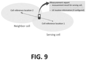
- the UE may trigger a first measurement report when the distance between the UE and a reference location (e.g., referenceLocation1 (e.g., in [3] R2-2111614) of the serving cell becomes larger than a threshold (e.g., Thresh1 (e.g., in [3] R2-2111614)) and the distance between the UE and a reference location (e.g., referenceLocation2 (e.g., in [3] R2-2111614)) of a neighbor cell becomes shorter than another threshold (e.g., Thresh2 (e.g., in [3] R2-2111614)).
- a threshold e.g., Thresh1 (e.g., in [3] R2-2111614)
- Thresh2 e.g., in [3] R2-2111614
- the first information may be a measurement result based on radio condition.
- the first information may be radio condition measurement result(s).
- the first information may be cell quality of a serving cell and/or neighbor cell(s).
- the first information may be measurement results of (radio condition of) a serving cell and/or a neighbor cell.
- the first information may be measurement results of (radio condition of) the cell (e.g., serving cell and/or neighbor cell) triggering a measurement report.
- the first information may be measurement results of (radio condition of) the cell (e.g., serving cell and/or neighbor cell) triggered/fulfilled triggering event.
- the first information may be measurement result(s) of beam measurement result(s) of one or more cells.
- the first information may be derived from SSB and/or Channel State Information Reference Signal (CSI-RS).
- the first information may be represented by RSRP, Reference Signal Received Quality (RSRQ) and/or Signal Interference plus Noise Ratio (SINR).
- the first information may be the best non-serving cell on a frequency.
- the first information may be a list of beams and/or cells.
- the second information may be UE location information (e.g., CommonLocationInfo (e.g., in [2] 3GPP TS 38.331 V16.5.0)).
- the second information may be a measurement result based on UE location.
- the second information may be a measurement result based on the distance between the UE and a reference location.
- the second information may be location measurement result(s).
- the second information may be the distance between the UE and a serving cell and/or a neighbor cell.
- the second information may be a GNSS-based location information.
- the second information may be the GNSS coordinates of the UE.
- the second information may be a distance (e.g., in km) between the UE and a cell center.
- the second information may be a distance (e.g., in km) between the UE and the last reported UE location.
- the second information may be a Timing Advance (TA) value.
- the second information may be TA difference (from the
- the first information may not be omitted (e.g., may be provided, and/or included) in a second measurement report.
- the second information may be and/or not be provided/included in the second measurement report.
- the UE may not omit the first information in the second measurement report.
- the UE may provide and/or include the first information in the second measurement report.
- the UE may provide and/or include the second information in the second measurement report.
- the UE may not provide and/or include the second information in the second measurement report.
- the second measurement report may be triggered for the purpose of cell/beam quality reporting.
- the second measurement report may be triggered based on a configuration for radio condition report.
- the second measurement report may be triggered by a radio condition-based measurement event.
- the second measurement report (or UE location report) may be triggered based on a radio condition-based triggering event.
- the second measurement report may be triggered based on a period for radio condition report.
- the second measurement report may be triggered when a periodic timer (e.g., for radio condition report) expires.
- the second measurement report (or UE location report) may be triggered when the UE is in cell edge (e.g., distance from a reference location is larger than a threshold).
- the UE may receive a first configuration to trigger measurement reporting based on a first event (e.g. location-based triggering event (e.g., eventD1)).
- the UE may receive a second configuration to trigger measurement reporting based on a second event (e.g., radio condition-based triggering event (e.g., eventA5)).
- the first event e.g., location-based triggering event
- the first event may be triggered/fulfilled when the distance between the UE and a first reference location of a serving cell (e.g., referenceLocation1) becomes larger than a distance threshold and the distance between the UE and a second reference location of a first neighbor cell (e.g., referenceLocation2) becomes shorter than another distance threshold.
- the first neighbor cell may be a (candidate) target cell of the first event (e.g., location-based triggering event (e.g., eventD1)).
- the second event e.g., radio condition-based triggering event
- the first neighbor cell and the second neighbor cell may be different neighbor cells.
- the first neighbor cell and the second neighbor cell may be same neighbor cell.
- the first neighbor cell and the second neighbor cell may be a cell neighboring to the serving cell.
- the UE may trigger a first measurement report based on the first event (e.g., location-based triggering event (e.g., eventD1)).
- the UE may trigger a first measurement report when the distance between the UE and the first reference location of the serving cell (e.g., referenceLocation1) becomes larger than the distance threshold and the distance between the UE and the second reference location of the first neighbor cell (e.g., referenceLocation2) becomes shorter than the another distance threshold.
- the UE may not include measured radio condition of the first neighbor cell in the first measurement report.
- the measured radio condition of the first neighbor cell may be omitted or not included in the first measurement report.
- the UE may include measured radio condition of the serving cell in the first measurement report.
- the measured radio condition of the serving cell may be not omitted or be included in the first measurement report.
- the UE may include a (coarse) location information (of the UE) in the first measurement report, e.g., if configured by the network.
- the (coarse) location information (of the UE) may be included in the first measurement report, e.g., if configured by the network.
- the UE may not include the (coarse) location information (of the UE) in the first measurement report, e.g., if not configured by the network.
- the (coarse) location information (of the UE) may be not included in the first measurement report, e.g., if not configured by the network.
- the UE may transmit the first measurement report to the network.
- the UE may trigger a second measurement report based on the second event (e.g., radio condition-based triggering event (e.g., eventA5)).
- the UE may trigger a second measurement report when the measurement results (of radio condition) of the serving cell (or PCell) becomes worse than the RSRP threshold and the measurement results (of radio condition) of the second neighbor cell becomes better than the another RSRP threshold.
- the UE may include measured radio condition of the second neighbor cell in the second measurement report.
- the measured radio condition of the second neighbor cell may be not omitted or be included in the second measurement report.
- the UE may include measured radio condition of the serving cell in the second measurement report.
- the measured radio condition of the serving cell may be not omitted or be included in the second measurement report.
- the UE may include a (coarse) location information (of the UE) in the second measurement report, e.g., if configured by the network.
- the (coarse) location information (of the UE) may be included in the second measurement report, e.g., if configured by the network.
- the UE may not include the (coarse) location information (of the UE) in the second measurement report, e.g., if not configured by the network.
- the (coarse) location information (of the UE) may be not included in the second measurement report, e.g., if not configured by the network.
- the UE may transmit the second measurement report to the network.
- the UE may omit (at least) one or more first information in the first measurement report (or UE location report) if the content of the one or more first information is the same as the content reported last time.
- the UE may omit (at least) one or more first information in the first measurement report (or UE location report) if the content of the one or more of first information is not above a threshold.
- the UE may omit (at least) one or more first information in the first measurement report (or UE location report) if a timer (e.g., periodic timer) is not running.
- the UE may omit (at least) one or more first information in the first measurement report (or UE location report) if receiving a NW indication.
- one, some, and/or all instances of "below a threshold” may correspond to, may be supplemented with, and/or may be replaced by "shorter than a threshold” and/or “smaller than a threshold”.
- one, some, and/or all instances of "above a threshold” may correspond to, may be supplemented with, and/or may be replaced by "longer than a threshold” and/or “larger than a threshold”.
- triggering event may correspond to, may be supplemented with, and/or may be replaced by "event”, “measurement event”, “measurement triggering event” and/or “measurement report triggering event”.
- the triggering event may be an event to trigger measurement report.
- the UE location information may be a coarse and/or a finer location information.
- the UE location information may be a GNSS-based location information.
- the UE location information may be GNSS coordinate(s) and/or part of GNSS coordinate(s).
- the UE location information may be locationInfo, commonLocationInfo and/or locationCoordinate as specified in TS 38.331 (e.g., [2] 3GPP TS 38.331 V16.5.0).
- the cell quality may be the radio condition and/or signaling strength of a cell, measured/derived by the UE.
- the cell quality and/or radio condition of a cell/beam may be with respect to SSB and/or CSI-RS.
- the cell quality and/or radio condition of a cell/beam may be represented by RSRP, RSRQ, and/or SINR.
- the UE may receive one or more measurement reporting configurations (e.g., MeasConfig, ReportConfigNR ) comprising a triggering event (e.g., eventA1, eventA2, eventA3, eventA4, eventA5, eventD1) and/or an interval (e.g., ReportInterval ) of a periodic timer, for location report and/or radio condition report.
- a triggering event e.g., eventA1, eventA2, eventA3, eventA4, eventA5, eventD1
- an interval e.g., ReportInterval
- the UE may receive configurations related to location-based and/or radio condition-based measurement (report).
- the UE may be in a cell of a NTN.
- the UE may be connected to a cell of a NTN.
- the UE may be connected to a LEO, GEO, MEO, HEO, and/or HAPS.
- a cell may be, may refer to a NTN cell.
- the UE may be referred to as the UE or a RRC entity of the UE.
- the UE may be a NR device.
- the UE may be a NR-light device.
- the UE may be a reduced capability device.
- the UE may be a mobile phone.
- the UE may be a wearable device.
- the UE may be a sensor.
- the UE may be a stationary device.
- the network may be a network node.
- the network may be a base station.
- the network may be an access point.
- the network may be an eNB.
- the network may be a gNB.
- the network may be a gateway.
- a method 1000 for a UE in a wireless communication system comprises receiving a first configuration of measurement reporting and a second configuration of measurement reporting from a NW (step 1002), triggering a first measurement report based on the first measurement reporting configuration, wherein a first information is provided in the first measurement report (step 1004), and triggering a second measurement report based on the second measurement reporting configuration, wherein the first information is not provided in the second measurement report (step 1006).
- the first information may be one or more measurement results based on radio condition.
- the first measurement report is triggered for (the purpose of) cell/beam quality reporting.
- the second measurement report is triggered for (the purpose of) location reporting.
- the method further comprises providing a second information in the second measurement report, wherein the second information is provided or not provided in the first measurement report.
- the second information may be one or more measurement results based on UE location.
- the second information may be UE location information.
- the device 300 includes a program code 312 stored in memory 310 of the transmitter.
- the CPU 308 could execute program code 312 to: (i) receive a first configuration of measurement reporting and a second configuration of measurement reporting from a NW; (ii) trigger a first measurement report based on the first measurement reporting configuration, wherein a first information is provided in the first measurement report; and (iii) trigger a second measurement report based on the second measurement reporting configuration, wherein the first information is not provided in the second measurement report.
- the CPU 308 can execute the program code 312 to perform all of the described actions, steps, and methods described above, below, or otherwise herein.
- the device 300 includes a program code 312 stored in memory 310 of the transmitter.
- the CPU 308 could execute program code 312 to: (i) transmit a first configuration of measurement reporting and a second configuration of measurement reporting to a UE; (ii) receive, from the UE, a first measurement report triggered based on the first measurement reporting configuration, wherein a first information is provided in the first measurement report; and (iii) receive, from the UE, a second measurement report triggered based on the second measurement reporting configuration, wherein the first information is not provided in the second measurement report.
- the CPU 308 can execute the program code 312 to perform all of the described actions, steps, and methods described above, below, or otherwise herein.
- Information about UE TA could be reported by the UE to the NW in NTN. If enabled by the NW, the information about UE TA could be reported during/at a Random Access (RA) procedure (e.g., in MSGA/Msg3 or Msg5) using Medium Access Control (MAC) Control Element (CE). The information about UE TA could be reported in initial access and/or in RRC connected mode. The TA reporting during/at RA procedure would be enabled/disabled by system information. The TA reporting during/at RA procedure may be controlled by a parameter (e.g., enableTA-Report ) included in a system information. And the TA reporting in RRC connected mode is event-triggered (e.g., configured by NW).
- a parameter e.g., enableTA-Report
- the reporting event would be based on a TA offset threshold between current information about UE TA and the last successfully reported information about UE TA. For example, if the TA value of the UE change above the TA offset threshold (e.g., the difference between current TA and the last successfully reported TA is above an offset) in RRC connected mode, the UE would trigger the TA reporting.
- dedicated signaling e.g., RRC configuration
- RRC configuration is used to configure the UE to report UE location information and/or TA related information for the purpose of TA reporting in RRC connected mode.
- the UE may report the information related to UE-specific TA during/at RA procedure (e.g., in initial access) using a MAC CE, if the reporting is enabled by system information (e.g., enableTA-Report in a system information is set to enabled, enableTA-Report is present in a system information).
- the UE may not report the information related to UE-specific TA during/at RA procedure (e.g., in initial access), if the reporting is disabled by system information (e.g., enableTA-Report in a system information is not set to enabled, enableTA-Report is absent in a system information).
- the UE may report the information related to UE-specific TA in RRC connected mode if configured by dedicated signaling and (at least) a reporting event is fulfilled/triggered.
- the UE may be configured to report the information related to UE-specific TA with content as TA related information and/or UE location information in RRC connected mode.
- the UE may be configured to report the information related to UE-specific TA with content as TA related information using MAC CE in RRC connected mode.
- the UE may be configured to report the information related to UE-specific TA with content as UE location information using RRC signaling in RRC connected mode.
- the TA reporting in RRC connected mode may be enabled/disabled by system information.
- the TA reporting in RRC connected mode may not be enabled/disabled by system information.
- the UE may report the information related to UE-specific TA during/at RA procedure (e.g., for RRC reconfiguration with sync and/or handover) in RRC connected mode using MAC CE, if the reporting is enabled by system information (e.g., included in Handover (HO) command message).
- the UE may not report the information related to UE-specific TA during RA procedure (e.g., for RRC reconfiguration with sync and/or handover) in RRC connected mode, if the reporting is disabled by system information (e.g., included in HO command message).
- Assistance information for SSB-based Measurement Timing Configuration (SMTC) (and/or measurement gap) configuration could be reported by a UE to a NW in NTN.
- the report of the assistance information for SMTC (and/or measurement gap) configuration may be configured by the NW, e.g., via a dedicated signaling, via RRC signaling, via RRC reconfiguration.
- the report of the assistance information for SMTC (and/or measurement gap) configuration may be event-triggered. The event to trigger the report may be based on how far the UE has moved (e.g., distance between the current UE location and the last reported UE location, distance between the current UE location and the UE location where the last report is made). For example, if the UE has moved a distance above a configured threshold (e.g., the difference between the current UE location and the last reported UE location is above the configured threshold), the UE may trigger the report.
- a configured threshold e.g., the difference between the current UE location and the last
- the UE may receive a configuration of the report of the assistance information for SMTC (and/or measurement gap) configuration.
- the configuration may configure the UE to trigger the report, e.g., periodically, and/or event triggered. If (or in response to) a report being triggered, the UE includes the assistance information for SMTC (and/or measurement gap) configuration in the report.
- the assistance information for SMTC (and/or measurement gap) configuration may assist the NW to configure a (proper) SMTC (and/or measurement gap) configuration for the UE.
- the NW may derive (or calculate) the propagation delay difference for the UE between a serving cell and a neighbor cell (e.g., the difference of the propagation delay from a serving cell to the UE and the propagation delay from a neighbor cell to the UE) based on the assistance information.
- the NW may use ephemeris of the serving cell and/or the neighbor cell for the derivation.
- the assistance information for SMTC (and/or measurement gap) configuration may be related to UE location.
- the assistance information may be UE location.
- the assistance information may be coarse UE location.
- the assistance information may be fine UE location.
- the assistance information for SMTC (and/or measurement gap) configuration may be related to propagation delay.
- the assistance information may be propagation delay difference.
- the assistance information may be propagation delay.
- the propagation delay difference may be between a serving cell to the UE (or the UE to a serving cell) and at least a neighbor cell to the UE (or the UE to at least a neighbor cell).
- the propagation delay may be from a serving cell to the UE (or from the UE to a serving cell).
- the propagation delay may be from a neighbor cell to the UE (or from the UE to a neighbor cell).
- the UE could be configured to provide some assistance information to the NW, e.g., when the UE is in RRC connected state.
- the assistance information may include UE location-related information, TA-related information, SMTC-related information.
- the assistance information may be included in a UE assistance information report and/or a UE location report.
- the report may be transmitted via a RRC message), e.g., RRC Setup Complete message, RRC Resume Complete message, Measurement Report, UE Assistance Information.
- the UE assistance information report and/or a UE location report may be triggered based on an event and/or periodically.
- the UE assistance information report (and/or the UE location report) may serve more than one purpose.
- a measurement report (e.g., as specified in NR RRC specification TS 38.331 (e.g., [2] 3GPP TS 38.331 V16.5.0)) may include a variety of information in addition to UE location (e.g., measurement result(s) of serving cell(s), measurement result(s) of neighbor cell(s), beam measurement result(s), best non-serving cell on a frequency, etc.).
- the information may be used to assist the NW for handover decisions (e.g., when to handover, which target cell to handover).
- a measurement report is triggered (e.g., based on a triggering event and/or a periodical reporting timer as specified in TS 38.331 (e.g., [2] 3GPP TS 38.331 V16.5.0)) for at least some purposes mentioned above (e.g., location requirement for NW to derive Cell ID, UE-specific TA change, SMTC and/or measurement gap configuration), at least some information other than UE location information in the measurement report may be less useful.
- the measurement result(s) of neighbor cell(s) may not be useful when the UE is not in the cell edge.
- the measurement result(s) of serving cell quality may not differ too much in a NTN cell due to near-far effect as specified in TR 38.821 (e.g., [5] 3GPP TR 38.821 V16.0.0).
- the UE may need to report the location information more frequently while at least some other information in the measurement report may be not changed (or not change too much). In such case(s), if the UE reports whole measurement report with the configured information, signaling overhead may be significant. Some methods to reduce the signaling overhead should be considered.
- the same assistance information (e.g., UE location) may be configured to be reported based on different triggers (e.g., based on UE moving distance, based on UE-specific TA change, based on location-based triggering event).
- the report may be transmitted via the same RRC message (e.g., measurement report).
- the content of the UE assistance information report may not necessarily be the same.
- Some (additional) information may be useful for some trigger but not useful for some other trigger.
- some information may be needed to differentiate the triggers. What information should be included in a UE assistance information report should be considered carefully in order to not induce unnecessary signaling overhead.
- the content of a UE assistance information report could be different from each other, e.g., based on its trigger.
- Information included in a first UE assistance information report could be different from information included in a second UE assistance information report.
- the UE assistance information report may be a UE location report, a measurement report, and/or a TA report.
- the UE assistance information report may be a UE assistance information message, a measurement report message, and/or a RRC message including UE location information.
- the measurement report may be triggered based on a location-based triggering event and/or a radio condition-based triggering event.
- a first information may be omitted (e.g., not provided, not included) in the first UE assistance information report.
- the UE may omit (at least) one or more first information in the first UE assistance information report.
- the UE may not provide and/or include (at least) one or more first information in the first UE assistance information report.
- a second information may be provided and/or included in the first UE assistance information report.
- the UE may provide and/or include (at least) one or more second information in the first UE assistance information report.
- the first information may not be omitted (e.g., may be provided, and/or included) in a second UE assistance information report.
- the second information may be and/or not be provided/included in the second UE assistance information report.
- the UE may not omit the first information in the second UE assistance information report.
- the UE may provide and/or include the first information in the second UE assistance information report.
- the UE may provide and/or include the second information in the second UE assistance information report.
- the UE may not provide and/or include the second information in the second UE assistance information report.
- the UE may omit (at least) one or more first information in the first UE assistance information report if the content of the one or more first information is the same as the content reported last time.
- the UE may omit (at least) one or more first information in the first UE assistance information report if the value of the one or more first information does not change above a threshold.
- the UE may omit (at least) one or more first information in the first UE assistance information report if a timer (e.g., periodic timer) is not running.
- the UE may omit (at least) one or more first information in the first UE assistance information report if receiving a NW indication.
- the first UE assistance information report and the second UE assistance information report may be differentiated based on a purpose of the report.
- the first UE assistance information report may be for a first purpose.
- the second UE assistance information report may be for a second purpose.
- the first purpose is different from the second purpose.
- the first purpose and/or the second purpose may be at least one of purposes specified in the following:
- the first UE assistance information report and the second UE assistance information report may be differentiated based on a condition (or trigger) to trigger the report.
- the first UE assistance information report may be triggered by a first trigger.
- the second UE assistance information report may be triggered by a second trigger.
- the first trigger is different from the second trigger.
- the first trigger and/or the second trigger may be at least one of the triggers specified in the following:
- the first UE assistance information report and the second UE assistance information report may be differentiated based on a message to transmit the report.
- the first UE assistance information report may be transmitted using a first message.
- the second UE assistance information report may be transmitted using a second message.
- the first message is different from the second message.
- the first message and/or the second message may be at least one of the messages specified in the following:
- the first UE assistance information report and the second UE assistance information report may be differentiated based on a configuration.
- the first UE assistance information report may be triggered based on a first configuration.
- the second UE assistance information report may be triggered based on a second configuration.
- the first configuration is different from the second configuration.
- the first configuration and/or the second configuration may be at least one of the configurations specified in the following:
- the first UE assistance information report and the second UE assistance information report may be differentiated based on a cell type.
- the cell may be a serving cell of the UE.
- the first UE assistance information report may be triggered when a serving cell of the UE is of a first type.
- the second report may be when a serving cell of the UE is of a second type.
- the first type is different from the second type.
- the first type and/or the second type may be at least one of the types specified in the following
- the first UE assistance information report and the second UE assistance information report may be differentiated based on location of the UE.
- the first UE assistance information report may be triggered when the UE is in a first location.
- the second UE assistance information report may be when the UE is in a second location.
- the first location is different from the second location.
- the first location and/or the second location may be at least one of the locations specified in the following:
- More than one differentiation mentioned above may be used jointly to differentiate the first UE assistance information report and the second UE assistance information report.
- the first information may be a radio measurement-related information.
- the second information may be a radio measurement-related information.
- the radio measurement-related information may be one or more of the following:
- the first information may be a UE location-related information.
- the second information may be a UE location-related information.
- the UE location-related information may be one or more of the following:
- the first information may be a TA-related information.
- the second information may be a TA-related information.
- the TA-related information may be one or more of the following:
- the first information may be a SMTC-related information.
- the second information may be a SMTC-related information.
- the SMTC-related information may be one or more of the following:
- the first information and/or the second information may be one or more of the following:
- a method 1010 for a UE in a wireless communication system comprises receiving a first configuration of UE assistance information and a second configuration of UE assistance information from a NW (step 1012), triggering a first UE assistance information report based on the first configuration, wherein a first information is provided in the first UE assistance information report (step 1014), and triggering a second UE assistance information report based on the second configuration, wherein the first information is not provided in the second UE assistance information report (step 1016).
- the method further comprises providing a second information in the second UE assistance information report, wherein the second information is provided or not provided in the first UE assistance information report.
- the first information may be one or more measurement results based on radio condition.
- the first UE assistance information report is triggered for (the purpose of) cell/beam quality reporting.
- the second UE assistance information report is triggered for (the purpose of) location reporting.
- the second UE assistance information report is triggered for (the purpose of) TA reporting.
- the second UE assistance information report is triggered for (the purpose of) SMTC (re)configuration.
- the second information may be one or more measurement result based on UE location.
- the second information may be UE location information.
- the device 300 includes a program code 312 stored in memory 310 of the transmitter.
- the CPU 308 could execute program code 312 to: (i) receive a first configuration of UE assistance information and a second configuration of UE assistance information from a NW; (ii) trigger a first UE assistance information report based on the first configuration, wherein a first information is provided in the first UE assistance information report; and (iii) trigger a second UE assistance information report based on the second configuration, wherein the first information is not provided in the second UE assistance information report.
- the CPU 308 can execute the program code 312 to perform all of the described actions, steps, and methods described above, below, or otherwise herein.
- the device 300 includes a program code 312 stored in memory 310 of the transmitter.
- the CPU 308 could execute program code 312 to: (i) transmit a first configuration of UE assistance information and a second configuration of UE assistance information; (ii) receive, from the UE, a first UE assistance information report triggered based on the first configuration, wherein a first information is provided in the first UE assistance information report; and (iii) receive, from the UE, a second UE assistance information report triggered based on the second configuration, wherein the first information is not provided in the second UE assistance information report.
- the CPU 308 can execute the program code 312 to perform all of the described actions, steps, and methods described above, below, or otherwise herein.
- a method 1020 for a UE in a wireless communication system comprises receiving a first configuration to trigger measurement reporting based on a first event that distance between the UE and a first reference location of a serving cell becomes larger than a distance threshold and distance between the UE and a second reference location of a first neighbor cell becomes shorter than another distance threshold (step 1022), and triggering a first measurement report based on the first event, wherein measured radio condition of the first neighbor cell is omitted or not included in the first measurement report (step 1024).
- the first event is a location-based triggering event.
- the method further comprises including a (coarse) location information in the first measurement report.
- the first reference location of the serving cell is referenceLocation1 and the second reference location of the first neighbor cell is referenceLocation2.
- the method further comprises receiving a second configuration to trigger measurement reporting based on a second event that measurement result (of radio condition) of a serving cell (or PCell) becomes worse than a Reference Signal Received Power (RSRP) threshold and measurement result (of radio condition) of a second neighbor cell becomes better than another RSRP threshold; and triggering a second measurement report based on the second event, wherein measured radio condition of the serving cell and/or the second neighbor cell is included or not omitted in the second measurement report.
- RSRP Reference Signal Received Power
- the second event is a radio condition based triggering event.
- the first neighbor cell and the second neighbor cell are the same cell.
- the UE determines to include measured radio condition of a neighbor cell based on triggering of the measurement report.
- the first measurement report and the second measurement report are differentiated based on triggering of the measurement report.
- the method further comprises determining to not include measured radio condition of a neighbor cell in a measurement report, wherein the measurement report is triggered by a location-based triggering event associated with the neighbor cell.
- the method further comprises transmitting the first measurement report and/or the second measurement report to a network.
- measured radio condition of the first neighbor cell is not included and measured radio condition of the serving cell is included in the first measurement report.
- the device 300 includes a program code 312 stored in memory 310 of the transmitter.
- the CPU 308 could execute program code 312 to: (i) receive a first configuration to trigger measurement reporting based on a first event that distance between the UE and a first reference location of a serving cell becomes larger than a distance threshold and distance between the UE and a second reference location of a first neighbor cell becomes shorter than another distance threshold; and (ii) trigger a first measurement report based on the first event, wherein measured radio condition of the first neighbor cell is omitted or not included in the first measurement report.
- the CPU 308 can execute the program code 312 to perform all of the described actions, steps, and methods described above, below, or otherwise herein.
- the device 300 includes a program code 312 stored in memory 310 of the transmitter.
- the CPU 308 could execute program code 312 to: (i) transmit a first configuration to trigger measurement reporting based on a first event that distance between a UE and a first reference location of a serving cell becomes larger than a distance threshold and distance between the UE and a second reference location of a first neighbor cell becomes shorter than another distance threshold; and (ii) receive, from the UE, a first measurement report triggered based on the first event, wherein measured radio condition of the first neighbor cell is omitted or not included in the first measurement report.
- the CPU 308 can execute the program code 312 to perform all of the described actions, steps, and methods described above, below, or otherwise herein.
- concurrent channels may be established based on pulse repetition frequencies. In some aspects, concurrent channels may be established based on pulse position or offsets. In some aspects, concurrent channels may be established based on time hopping sequences. In some aspects, concurrent channels may be established based on pulse repetition frequencies, pulse positions or offsets, and time hopping sequences.
- the various illustrative logical blocks, modules, and circuits described in connection with the aspects disclosed herein may be implemented within or performed by an integrated circuit ("IC"), an access terminal, or an access point.
- the IC may comprise a general purpose processor, a digital signal processor (DSP), an application specific integrated circuit (ASIC), a field programmable gate array (FPGA) or other programmable logic device, discrete gate or transistor logic, discrete hardware components, electrical components, optical components, mechanical components, or any combination thereof designed to perform the functions described herein, and may execute codes or instructions that reside within the IC, outside of the IC, or both.
- a general purpose processor may be a microprocessor, but in the alternative, the processor may be any conventional processor, controller, microcontroller, or state machine.
- a processor may also be implemented as a combination of computing devices, e.g., a combination of a DSP and a microprocessor, a plurality of microprocessors, one or more microprocessors in conjunction with a DSP core, or any other such configuration.
- a software module e.g., including executable instructions and related data
- other data may reside in a data memory such as RAM memory, flash memory, ROM memory, EPROM memory, EEPROM memory, registers, a hard disk, a removable disk, a CD-ROM, or any other form of computer-readable storage medium known in the art.
- a sample storage medium may be coupled to a machine such as, for example, a computer/processor (which may be referred to herein, for convenience, as a "processor") such the processor can read information (e.g., code) from and write information to the storage medium.
- a sample storage medium may be integral to the processor.
- the processor and the storage medium may reside in an ASIC.
- the ASIC may reside in user equipment.
- the processor and the storage medium may reside as discrete components in user equipment.
- any suitable computer-program product may comprise a computer-readable medium comprising codes relating to one or more of the aspects of the disclosure.
- a computer program product may comprise packaging materials.
Landscapes
- Engineering & Computer Science (AREA)
- Computer Networks & Wireless Communication (AREA)
- Signal Processing (AREA)
- Physics & Mathematics (AREA)
- General Physics & Mathematics (AREA)
- Astronomy & Astrophysics (AREA)
- Radar, Positioning & Navigation (AREA)
- Remote Sensing (AREA)
- Mobile Radio Communication Systems (AREA)
Abstract
Description
- This disclosure generally relates to wireless communication networks and, more particularly, to a method and apparatus for User Equipment (UE) location reporting in a wireless communication system to facilitate efficiency in location information reporting in Non-Terrestrial Networks (NTNs).
- With the rapid rise in demand for communication of large amounts of data to and from mobile communication devices, traditional mobile voice communication networks are evolving into networks that communicate with Internet Protocol (IP) data packets. Such IP data packet communication can provide users of mobile communication devices with voice over IP, multimedia, multicast and on-demand communication services.
- An exemplary network structure is an Evolved Universal Terrestrial Radio Access Network (E-UTRAN). The E-UTRAN system can provide high data throughput in order to realize the above-noted voice over IP and multimedia services. A new radio technology for the next generation (e.g., 5G) is currently being discussed by the 3GPP standards organization. Accordingly, changes to the current body of 3GPP standard are currently being submitted and considered to evolve and finalize the 3GPP standard.
- Methods, systems, and apparatuses are provided for User Equipment (UE) location reporting in a wireless communication system to facilitate efficiency in measurement reporting in Non-Terrestrial Networks (NTNs). A method and a UE according to the invention are defined by the independent claims, respectively.
- In various embodiments, with this and other concepts, systems, and methods of the present invention, a method for a UE in a wireless communication system comprises receiving a first configuration to trigger measurement reporting based on a first event that distance between the UE and a first reference location of a serving cell becomes larger than a distance threshold and distance between the UE and a second reference location of a first neighbor cell becomes shorter than another distance threshold, and triggering a first measurement report based on the first event, wherein measured radio condition of the first neighbor cell is omitted or not included in the first measurement report.
-
-
FIG. 1 shows a diagram of a wireless communication system, in accordance with embodiments of the present invention. -
FIG. 2 is a block diagram of a transmitter system (also known as access network) and a receiver system (also known as user equipment or UE), in accordance with embodiments of the present invention. -
FIG. 3 is a functional block diagram of a communication system, in accordance with embodiments of the present invention. -
FIG. 4 is a functional block diagram of the program code ofFIG. 3 , in accordance with embodiments of the present invention. -
FIG. 5 is a reproduction of Figure 5.5.5.1-1: Measurement reporting, from 3GPP TS 38.331 V16.5.0, "NR, RRC protocol specification". -
FIG. 6 illustrates an example of the concept of a location-based event, in accordance with embodiments of the present invention. -
FIG. 7 illustrates an example for measurement reporting triggered by a radio condition-based event, in accordance with embodiments of the present invention. -
FIG. 8 illustrates an example for measurement reporting triggered by a location-based event, in accordance with embodiments of the present invention. -
FIG. 9 illustrates an example for a UE triggering a first measurement report based on the location-based triggering event, in accordance with embodiments of the present invention. -
FIG. 10 is a flow diagram of a method of a UE receiving a first configuration of measurement reporting and a second configuration of measurement reporting from a NW, in accordance with embodiments of the present invention. -
FIG. 11 is a flow diagram of a method of a UE receiving a first configuration of UE assistance information and a second configuration of UE assistance information from a NW, in accordance with embodiments of the present invention. -
FIG. 12 is a flow diagram of a method of a UE receiving a first configuration to trigger measurement reporting based on a first event, in accordance with embodiments of the present invention. - The invention described herein can be applied to or implemented in exemplary wireless communication systems and devices described below. In addition, the invention is described mainly in the context of the 3GPP architecture reference model. However, it is understood that with the disclosed information, one skilled in the art could easily adapt for use and implement aspects of the invention in a 3GPP2 network architecture as well as in other network architectures.
- The exemplary wireless communication systems and devices described below employ a wireless communication system, supporting a broadcast service. Wireless communication systems are widely deployed to provide various types of communication such as voice, data, and so on. These systems may be based on code division multiple access (CDMA), time division multiple access (TDMA), orthogonal frequency division multiple access (OFDMA), 3GPP LTE (Long Term Evolution) wireless access, 3GPP LTE-A (Long Term Evolution Advanced) wireless access, 3GPP2 UMB (Ultra Mobile Broadband), WiMax, 3GPP NR (New Radio), or some other modulation techniques.
- In particular, the exemplary wireless communication systems and devices described below may be designed to support one or more standards such as the standard offered by a consortium named "3rd Generation Partnership Project" referred to herein as 3GPP, including: [1] RP-201256, "Solutions for NR to support non-terrestrial networks (NTN)"; [2] 3GPP TS 38.331 V16.5.0, "NR, RRC protocol specification"; [3] R2-2111614, "Stage-3 running RRC CR for NTN Rel-17"; [4] RP-211774, "Status Report to TSG"; [5] 3GPP TR 38.821 V16.0.0, "Solutions for NR to support non-terrestrial networks (NTN)"; [6] R2-2011041, "Reply LS on SA WG2 assumptions from conclusion of study on architecture aspects for using satellite access in 5G"; [7] R2-2111221, "LS on UE TA reporting"; [8] R2-2111333, "[116-e][103][NTN] SMTC/gaps (Nokia)"; and [9] RP-212803, "Status report WI NR-NTN-solutions". The standards and documents listed above are hereby expressly and fully incorporated herein by reference in their entirety.
-
FIG. 1 shows a multiple access wireless communication system according to one embodiment of the invention. An access network 100 (AN) includes multiple antenna groups, one including 104 and 106, another including 108 and 110, and an additional including 112 and 114. InFIG. 1 , only two antennas are shown for each antenna group, however, more or fewer antennas may be utilized for each antenna group. Access terminal (AT) 116 is in communication withantennas antennas terminal 116 overforward link 120 and receive information from AT 116 overreverse link 118. AT 122 is in communication withantennas antennas forward link 126 and receive information from AT 122 overreverse link 124. In a FDD system,communication links forward link 120 may use a different frequency than that used byreverse link 118. - Each group of antennas and/or the area in which they are designed to communicate is often referred to as a sector of the access network. In the embodiment, antenna groups each are designed to communicate to access terminals in a sector of the areas covered by
access network 100. - In communication over
forward links access network 100 may utilize beamforming in order to improve the signal-to-noise ratio of forward links for thedifferent access terminals - The AN may be a fixed station or base station used for communicating with the terminals and may also be referred to as an access point, a Node B, a base station, an enhanced base station, an eNodeB, or some other terminology. The AT may also be called User Equipment (UE), a wireless communication device, terminal, access terminal or some other terminology.
-
FIG. 2 is a simplified block diagram of an embodiment of a transmitter system 210 (also known as the access network) and a receiver system 250 (also known as access terminal (AT) or user equipment (UE)) in aMIMO system 200. At thetransmitter system 210, traffic data for a number of data streams is provided from adata source 212 to a transmit (TX)data processor 214. - Preferably, each data stream is transmitted over a respective transmit antenna. TX
data processor 214 formats, codes, and interleaves the traffic data for each data stream based on a particular coding scheme selected for that data stream to provide coded data. - The coded data for each data stream may be multiplexed with pilot data using OFDM techniques. The pilot data is typically a known data pattern that is processed in a known manner and may be used at the receiver system to estimate the channel response. The multiplexed pilot and coded data for each data stream is then modulated (e.g., symbol mapped) based on a particular modulation scheme (e.g., BPSK, QPSK, M-PSK, or M-QAM) selected for that data stream to provide modulation symbols. The data rate, coding, and modulation for each data stream may be determined by instructions performed by
processor 230. Amemory 232 is coupled toprocessor 230. - The modulation symbols for all data streams are then provided to a
TX MIMO processor 220, which may further process the modulation symbols (e.g., for OFDM). TX MIMOprocessor 220 then provides NT modulation symbol streams to NT transmitters (TMTR) 222a through 222t. In certain embodiments, TXMIMO processor 220 applies beamforming weights to the symbols of the data streams and to the antenna from which the symbol is being transmitted. - Each transmitter 222 receives and processes a respective symbol stream to provide one or more analog signals, and further conditions (e.g., amplifies, filters, and upconverts) the analog signals to provide a modulated signal suitable for transmission over the MIMO channel. NT modulated signals from
transmitters 222a through 222t are then transmitted from NT antennas 224a through 224t, respectively. - At
receiver system 250, the transmitted modulated signals are received by NR antennas 252a through 252r and the received signal from each antenna 252 is provided to a respective receiver (RCVR) 254a through 254r. Each receiver 254 conditions (e.g., filters, amplifies, and downconverts) a respective received signal, digitizes the conditioned signal to provide samples, and further processes the samples to provide a corresponding "received" symbol stream. - An RX
data processor 260 then receives and processes the NR received symbol streams from NR receivers 254 based on a particular receiver processing technique to provide NT "detected" symbol streams. The RXdata processor 260 then demodulates, deinterleaves, and decodes each detected symbol stream to recover the traffic data for the data stream. The processing by RXdata processor 260 is complementary to that performed by TX MIMOprocessor 220 and TXdata processor 214 attransmitter system 210. - A
processor 270 periodically determines which pre-coding matrix to use (discussed below).Processor 270 formulates a reverse link message comprising a matrix index portion and a rank value portion. - The reverse link message may comprise various types of information regarding the communication link and/or the received data stream. The reverse link message is then processed by a
TX data processor 238, which also receives traffic data for a number of data streams from adata source 236, modulated by amodulator 280, conditioned bytransmitters 254a through 254r, and transmitted back totransmitter system 210. - At
transmitter system 210, the modulated signals fromreceiver system 250 are received by antennas 224, conditioned by receivers 222, demodulated by ademodulator 240, and processed by aRX data processor 242 to extract the reserve link message transmitted by thereceiver system 250.Processor 230 then determines which pre-coding matrix to use for determining the beamforming weights then processes the extracted message. -
Memory 232 may be used to temporarily store some buffered/computational data from 240 or 242 throughProcessor 230, store some buffed data from 212, or store some specific program codes. AndMemory 272 may be used to temporarily store some buffered/computational data from 260 throughProcessor 270, store some buffed data from 236, or store some specific program codes. - Turning to
FIG. 3 , this figure shows an alternative simplified functional block diagram of a communication device according to one embodiment of the invention. As shown inFIG. 3 , the communication device 300 in a wireless communication system can be utilized for realizing the UEs (or ATs) 116 and 122 inFIG. 1 , and the wireless communications system is preferably the NR system. The communication device 300 may include aninput device 302, anoutput device 304, acontrol circuit 306, a central processing unit (CPU) 308, amemory 310, aprogram code 312, and atransceiver 314. Thecontrol circuit 306 executes theprogram code 312 in thememory 310 through theCPU 308, thereby controlling an operation of the communications device 300. The communications device 300 can receive signals input by a user through theinput device 302, such as a keyboard or keypad, and can output images and sounds through theoutput device 304, such as a monitor or speakers. Thetransceiver 314 is used to receive and transmit wireless signals, delivering received signals to thecontrol circuit 306, and outputting signals generated by thecontrol circuit 306 wirelessly. -
FIG. 4 is a simplified block diagram of theprogram code 312 shown inFIG. 3 in accordance with an embodiment of the invention. In this embodiment, theprogram code 312 includes anapplication layer 400, aLayer 3portion 402, and aLayer 2portion 404, and is coupled to aLayer 1portion 406. TheLayer 3portion 402 generally performs radio resource control. TheLayer 2portion 404 generally performs link control. TheLayer 1portion 406 generally performs physical connections. - For LTE, LTE-A, or NR systems, the
Layer 2portion 404 may include a Radio Link Control (RLC) layer and a Medium Access Control (MAC) layer. TheLayer 3portion 402 may include a Radio Resource Control (RRC) layer. - Any two or more than two of the following paragraphs, (sub-)bullets, points, actions, or claims described in each invention paragraph or section may be combined logically, reasonably, and properly to form a specific method.
- Any sentence, paragraph, (sub-)bullet, point, action, or claim described in each of the following invention paragraphs or sections may be implemented independently and separately to form a specific method or apparatus. Dependency, e.g., "based on", "more specifically", "example", etc., in the following invention disclosure is just one possible embodiment which would not restrict the specific method or apparatus.
- The description of the work item of non-terrestrial networks (NTN) in NR is specified in [1] RP-201256, "Solutions for NR to support non-terrestrial networks (NTN)":
- [...] The following control plane procedures enhancements should be specified (see TR 38.821)
- Idle mode:
- ∘ Definition of additional assistance information for cell selection/reselection (e.g. using UE location information, satellite Ephemeris information)
- ∘ Definition of NTN (satellite/HAPS) cell specific information in SIB
- Connected mode
- ∘ Enhancement necessary to take into account location information (UE & Satellite/HAPS) and/or ephemeris in determining when to perform hand-over, in order to have a high degree of hand-over control for hand-over robustness and coverage management.
- ∘ Enhancement to existing measurement configurations to address absolute propagation delay difference between satellites (e.g. SMTC measurement gap adaptation to the SSB/CSI-RS measurement window) [RAN2/4] .
- Service continuity for mobility from TN to NTN and from NTN to TN systems (to be addressed when connected mode mobility has sufficiently progressed)
- Identify potential issues associated to the use of the existing Location Services (LCS) application protocols to locate UE in the context of NTN and specify adaptations if any [RAN2/3]
- The measurement report and related configurations are specified in [2] 3GPP TS 38.331 V16.5.0, "NR, RRC protocol specification" as below:
- The network may configure an RRC_CONNECTED UE to perform measurements. The network may configure the UE to report them in accordance with the measurement configuration or perform conditional reconfiguration evaluation in accordance with the conditional reconfiguration. The measurement configuration is provided by means of dedicated signalling i.e. using the RRCReconfiguration or RRCResume.
- The network may configure the UE to perform the following types of measurements:
- NR measurements;
- Inter-RAT measurements of E-UTRA frequencies.
- Inter-RAT measurements of UTRA-FDD frequencies.
- The network may configure the UE to report the following measurement information based on SS/PBCH block(s):
- Measurement results per SS/PBCH block;
- Measurement results per cell based on SS/PBCH block(s);
- SS/PBCH block(s) indexes.
- The network may configure the UE to report the following measurement information based on CSI-RS resources:
- Measurement results per CSI-RS resource;
- Measurement results per cell based on CSI-RS resource(s);
- CSI-RS resource measurement identifiers.
- [...] The measurement configuration includes the following parameters:
- 1. Measurement objects: A list of objects on which the UE shall perform the measurements.
- For intra-frequency and inter-frequency measurements a measurement object indicates the frequency/time location and subcarrier spacing of reference signals to be measured. Associated with this measurement object, the network may configure a list of cell specific offsets, a list of 'blacklisted' cells and a list of 'whitelisted' cells. Blacklisted cells are not applicable in event evaluation or measurement reporting. Whitelisted cells are the only ones applicable in event evaluation or measurement reporting.
- The measObjectId of the MO which corresponds to each serving cell is indicated by servingCellMO within the serving cell configuration.
- For inter-RAT E-UTRA measurements a measurement object is a single E-UTRA carrier frequency. Associated with this E-UTRA carrier frequency, the network can configure a list of cell specific offsets, a list of 'blacklisted' cells and a list of 'whitelisted' cells. Blacklisted cells are not applicable in event evaluation or measurement reporting. Whitelisted cells are the only ones applicable in event evaluation or measurement reporting.
- For inter-RAT UTRA-FDD measurements a measurement object is a set of cells on a single UTRA-FDD carrier frequency.
- For CBR measurement of NR sidelink communication, a measurement object is a set of transmission resource pool(s) on a single carrier frequency for NR sidelink communication.
- For CLI measurements a measurement object indicates the frequency/time location of SRS resources and/or CLI-RSSI resources, and subcarrier spacing of SRS resources to be measured.
- 2. Reporting configurations: A list of reporting configurations where there can be one or multiple reporting configurations per measurement object. Each measurement reporting configuration consists of the following:
- Reporting criterion: The criterion that triggers the UE to send a measurement report. This can either be periodical or a single event description.
- RS type: The RS that the UE uses for beam and cell measurement results (SS/PBCH block or CSI-RS).
- Reporting format: The quantities per cell and per beam that the UE includes in the measurement report (e.g. RSRP) and other associated information such as the maximum number of cells and the maximum number beams per cell to report.
- In case of conditional reconfiguration, each configuration consists of the following:
- Execution criteria: The criteria the UE uses for conditional reconfiguration execution.
- RS type: The RS that the UE uses for obtaining beam and cell measurement results (SS/PBCH block-based or CSI-RS-based), used for evaluating conditional reconfiguration execution condition.
- 3. Measurement identities: For measurement reporting, a list of measurement identities where each measurement identity links one measurement object with one reporting configuration. By configuring multiple measurement identities, it is possible to link more than one measurement object to the same reporting configuration, as well as to link more than one reporting configuration to the same measurement object. The measurement identity is also included in the measurement report that triggered the reporting, serving as a reference to the network. For conditional reconfiguration triggering, one measurement identity links to exactly one conditional reconfiguration trigger configuration. And up to 2 measurement identities can be linked to one conditional reconfiguration execution condition.
- 4. Quantity configurations: The quantity configuration defines the measurement filtering configuration used for all event evaluation and related reporting, and for periodical reporting of that measurement. For NR measurements, the network may configure up to 2 quantity configurations with a reference in the NR measurement object to the configuration that is to be used. In each configuration, different filter coefficients can be configured for different measurement quantities, for different RS types, and for measurements per cell and per beam.
- 5. Measurement gaps: Periods that the UE may use to perform measurements.
- A UE in RRC_CONNECTED maintains a measurement object list, a reporting configuration list, and a measurement identities list according to signalling and procedures in this specification. The measurement object list possibly includes NR measurement object(s), CLI measurement object(s) and inter-RAT objects. Similarly, the reporting configuration list includes NR and inter-RAT reporting configurations. Any measurement object can be linked to any reporting configuration of the same RAT type. Some reporting configurations may not be linked to a measurement object. Likewise, some measurement objects may not be linked to a reporting configuration.
- The measurement procedures distinguish the following types of cells:
- 1. The NR serving cell(s) - these are the SpCell and one or more SCells.
- 2. Listed cells - these are cells listed within the measurement object(s).
- 3. Detected cells - these are cells that are not listed within the measurement object(s) but are detected by the UE on the SSB frequency(ies) and subcarrier spacing(s) indicated by the measurement object(s).
- For NR measurement object(s), the UE measures and reports on the serving cell(s), listed cells and/or detected cells. For inter-RAT measurements object(s) of E-UTRA, the UE measures and reports on listed cells and detected cells and, for RSSI and channel occupancy measurements, the UE measures and reports on the configured resources on the indicated frequency. For inter-RAT measurements object(s) of UTRA-FDD, the UE measures and reports on listed cells. For CLI measurement object(s), the UE measures and reports on configured measurement resources (i.e. SRS resources and/or CLI-RSSI resources).
- Whenever the procedural specification, other than contained in sub-clause 5.5.2, refers to a field it concerns a field included in the VarMeasConfig unless explicitly stated otherwise i.e. only the measurement configuration procedure covers the direct UE action related to the received measConfig.
- An RRC_CONNECTED UE shall derive cell measurement results by measuring one or multiple beams associated per cell as configured by the network, as described in 5.5.3.3. For all cell measurement results, except for RSSI, and CLI measurement results in RRC_CONNECTED, the UE applies the
layer 3 filtering as specified in 5.5.3.2, before using the measured results for evaluation of reporting criteria, measurement reporting or the criteria to trigger conditional reconfiguration execution. For cell measurements, the network can configure RSRP, RSRQ, SINR, RSCP or EcN0 as trigger quantity. For CLI measurements, the network can configure SRS-RSRP or CLI-RSSI as trigger quantity. For cell and beam measurements, reporting quantities can be any combination of quantities (i.e. only RSRP; only RSRQ; only SINR; RSRP and RSRQ; RSRP and SINR; RSRQ and SINR; RSRP, RSRQ and SINR; only RSCP; only EcN0; RSCP and EcN0), irrespective of the trigger quantity, and for CLI measurements, reporting quantities can be either SRS-RSRP or CLI-RSSI. For conditional reconfiguration execution, the network can configure up to 2 quantities, both using same RS type. The UE does not apply thelayer 3 filtering as specified in 5.5.3.2 to derive the CBR measurements. - The network may also configure the UE to report measurement information per beam (which can either be measurement results per beam with respective beam identifier(s) or only beam identifier(s)), derived as described in 5.5.3.3a. If beam measurement information is configured to be included in measurement reports, the UE applies the
layer 3 beam filtering as specified in 5.5.3.2. On the other hand, the exact L1 filtering of beam measurements used to derive cell measurement results is implementation dependent. - The UE shall:
- 1> whenever the UE has a measConfig, perform RSRP and RSRQ measurements for each serving cell for which servingCellMO is configured as follows:
- 2> if the reportConfig associated with at least one meαsId included in the measIdList within VarMeasConfig contains an rsType set to ssb and ssb-ConfigMobility is configured in the measObject indicated by the servingCellMO:
- 3> if the reportConfig associated with at least one meαsId included in the measIdList within VarMeasConfig contains a reportQuantityRS-Indexes and maxNrofRS-IndexesToReport and contains an rsType set to ssb:
4> derivelayer 3 filtered RSRP and RSRQ per beam for the serving cell based on SS/PBCH block, as described in 5.5.3.3a; - 3> derive serving cell measurement results based on SS/PBCH block, as described in 5.5.3.3;
- 3> if the reportConfig associated with at least one meαsId included in the measIdList within VarMeasConfig contains a reportQuantityRS-Indexes and maxNrofRS-IndexesToReport and contains an rsType set to ssb:
- 2> if the reportConfig associated with at least one meαsId included in the measIdList within VarMeasConfig contains an rsType set to csi-rs and CSI-RS-ResourceConfigMobility is configured in the measObject indicated by the servingCellMO:
- 3> if the reportConfig associated with at least one meαsId included in the measIdList within VarMeasConfig contains a reportQuantityRS-Indexes and maxNrofRS-IndexesToReport and contains an rsType set to csi-rs:
4> derivelayer 3 filtered RSRP and RSRQ per beam for the serving cell based on CSI-RS, as described in 5.5.3.3a; - 3> derive serving cell measurement results based on CSI-RS, as described in 5.5.3.3;
- 3> if the reportConfig associated with at least one meαsId included in the measIdList within VarMeasConfig contains a reportQuantityRS-Indexes and maxNrofRS-IndexesToReport and contains an rsType set to csi-rs:
- 2> if the reportConfig associated with at least one meαsId included in the measIdList within VarMeasConfig contains an rsType set to ssb and ssb-ConfigMobility is configured in the measObject indicated by the servingCellMO:
- 1> for each serving cell for which servingCellMO is configured, if the reportConfig associated with at least one measId included in the measIdList within VarMeasConfig contains SINR as trigger quantity and/or reporting quantity:
- 2> if the reportConfig contains rsType set to ssb and ssb-ConfigMobility is configured in the servingCellMO:
- 3> if the reportConfigcontains a reportQuantityRS-Indexes and maxNrojRS-IndexesToReport:
4> derivelayer 3 filtered SINR per beam for the serving cell based on SS/PBCH block, as described in 5.5.3.3a; - 3> derive serving cell SINR based on SS/PBCH block, as described in 5.5.3.3;
- 3> if the reportConfigcontains a reportQuantityRS-Indexes and maxNrojRS-IndexesToReport:
- 2> if the reportConfig contains rsType set to csi-rs and CSI-RS-ResourceConfigMobility is configured in the servingCellMO:
- 3> if the reportConfigcontains a reportQuantityRS-Indexes and maxNrofRS-IndexesToReport:
4> derivelayer 3 filtered SINR per beam for the serving cell based on CSI-RS, as described in 5.5.3.3a; - 3> derive serving cell SINR based on CSI-RS, as described in 5.5.3.3;
- 3> if the reportConfigcontains a reportQuantityRS-Indexes and maxNrofRS-IndexesToReport:
- 2> if the reportConfig contains rsType set to ssb and ssb-ConfigMobility is configured in the servingCellMO:
- 1> for each measId included in the measIdList within VarMeasConfig:
- [...]
- 2> if the reportType for the associated reportConfig is periodical, eventTriggered or condTriggerConfig:
- 3> if a measurement gap configuration is setup, or
- 3> if the UE does not require measurement gaps to perform the concerned measurements:
- 4> if s-MeasureConfig is not configured, or
- 4> if s-MeasureConfig is set to ssb-RSRP and the NR SpCell RSRP based on SS/PBCH block, after
layer 3 filtering, is lower than ssb-RSRP, or - 4> if s-MeasureConfig is set to csi-RSRP and the NR SpCell RSRP based on CSI-RS, after
layer 3 filtering, is lower than csi-RSRP:- 5> if the measObject is associated to NR and the rsType is set to csi-rs:
- 6> if reportQuantityRS-Indexes and maxNrofRS-IndexesToReport for the associated reportConfig are configured:
7> derivelayer 3 filtered beam measurements only based on CSI-RS for each measurement quantity indicated in reportQuantityRS-Indexes, as described in 5.5.3.3a; - 6> derive cell measurement results based on CSI-RS for the trigger quantity and each measurement quantity indicated in reportQuantityCell using parameters from the associated measObject, as described in 5.5.3.3;
- 6> if reportQuantityRS-Indexes and maxNrofRS-IndexesToReport for the associated reportConfig are configured:
- 5> if the measObject is associated to NR and the rsType is set to ssb:
- 6> if reportQuantityRS-Indexes and maxNrofRS-IndexesToReport for the associated reportConfig are configured:
7> derivelayer 3 beam measurements only based on SS/PBCH block for each measurement quantity indicated in reportQuantityRS-Indexes, as described in 5.5.3.3a; - 6> derive cell measurement results based on SS/PBCH block for the trigger quantity and each measurement quantity indicated in reportQuantityCell using parameters from the associated measObject, as described in 5.5.3.3;
- 6> if reportQuantityRS-Indexes and maxNrofRS-IndexesToReport for the associated reportConfig are configured:
- 5> if the measObject is associated to E-UTRA
6> perform the corresponding measurements associated to neighbouring cells on the frequencies indicated in the concerned measObject, as described in 5.5.3.2; - 5> if the measObject is associated to UTRA-FDD:
6> perform the corresponding measurements associated to neighbouring cells on the frequencies indicated in the concerned measObject, as described in 5.5.3.2;
- 5> if the measObject is associated to NR and the rsType is set to csi-rs:
- 4> if the measRSSI-ReportConfig is configured in the associated reportConfig:
5> perform the RSSI and channel occupancy measurements on the frequency indicated in the associated meαsObject;
- [...]
- If AS security has been activated successfully, the UE shall:
- 1> for each measId included in the measIdList within VarMeasConfig:
- 2> if the corresponding reportConfig includes a reportType set to eventTriggered or periodical:
- 3> if the corresponding measObject concerns NR:
- 4> if the corresponding reportConfig includes measRSSI-ReportConfig:
5> consider the resource indicated by the rmtc-Config on the associated frequency to be applicable; - 4> if the eventAl or eventA2 is configured in the corresponding reportConfig:
5> consider only the serving cell to be applicable; - 4> if the eventA3 or eventA5 is configured in the corresponding reportConfig:
5> if a serving cell is associated with a measObjectNR and neighbours are associated with another measObjectNR, consider any serving cell associated with the other measObjectNR to be a neighbouring cell as well; - 4> if corresponding reportConfig includes reportType set to periodical; or
- 4> for measurement events other than eventA1 or eventA2:
- 5> if useWhiteCellList is set to true:
6> consider any neighbouring cell detected based on parameters in the associated measObjectNR to be applicable when the concerned cell is included in the whiteCellsToAddModList defined within the VarMeasConfig for this measId; - 5> else:
6> consider any neighbouring cell detected based on parameters in the associated measObjectNR to be applicable when the concerned cell is not included in the blackCellsToAddModList defined within the VarMeasConfig for this measId;
- 5> if useWhiteCellList is set to true:
- 4> if the corresponding reportConfig includes measRSSI-ReportConfig:
- 3> if the corresponding measObject concerns NR:
- 2> if the reportType is set to eventTriggered and if the entry condition applicable for this event, i.e. the event corresponding with the eventId of the corresponding reportConfig within VarMeasConfig, is fulfilled for one or more applicable cells for all measurements after
layer 3 filtering taken during timeToTrigger defined for this event within the VarMeasConfig, while the VarMeasReportList does not include a measurement reporting entry for this meαsId (a first cell triggers the event):- 3> include a measurement reporting entry within the VarMeasReportList for this measId;
- 3> set the numberOfReportsSent defined within the VarMeasReportList for this measId to 0;
- 3> include the concerned cell(s) in the cellsTriggeredList defined within the VarMeasReportList for this measId;
- 3> if useT312 is set to true in reportConfig for this event:
- 4> if T310 for the corresponding SpCell is running; and
- 4> if T312 is not running for corresponding SpCell:
5> start timer T312 for the corresponding SpCell with the value of T312 configured in the corresponding measObjectNR;
- 3> initiate the measurement reporting procedure, as specified in 5.5.5;
- 2> else if the reportType is set to eventTriggered and if the entry condition applicable for this event, i.e. the event corresponding with the eventId of the corresponding reportConfig within VarMeasConfig, is fulfilled for one or more applicable cells not included in the cellsTriggeredList for all measurements after
layer 3 filtering taken during timeToTrigger defined for this event within the VarMeasConfig (a subsequent cell triggers the event):- 3> set the numberOfReportsSent defined within the VarMeasReportList for this meαsId to 0;
- 3> include the concerned cell(s) in the cellsTriggeredList defined within the VarMeasReportList for this measId;
- 3> if useT312 is set to true in reportConfig for this event:
- 4> if T310 for the corresponding SpCell is running; and
- 4> if T312 is not running for corresponding SpCell:
5> start timer T312 for the corresponding SpCell with the value of T312 configured in the corresponding measObjectNR;
- 3> initiate the measurement reporting procedure, as specified in 5.5.5;
- 2> else if the reportType is set to eventTriggered and if the leaving condition applicable for this event is fulfilled for one or more of the cells included in the cellsTriggeredList defined within the VarMeasReportList for this measId for all measurements after
layer 3 filtering taken during timeToTrigger defined within the VarMeasConfig for this event:- 3> remove the concerned cell(s) in the cellsTriggeredList defined within the VarMeasReportList for this measId;
- 3> if reportOnLeave is set to true for the corresponding reporting configuration:
4> initiate the measurement reporting procedure, as specified in 5.5.5; - 3> if the cellsTriggeredList defined within the VarMeasReportList for this meαsId is empty:
- 4> remove the measurement reporting entry within the VarMeasReportList for this meαsId;
- 4> stop the periodical reporting timer for this measId; if running;
- 2> else if the reportType is set to eventTriggered and if the entry condition applicable for this event, i.e. the event corresponding with the eventId of the corresponding reportConfig within VarMeasConfig, is fulfilled for one or more applicable transmission resource pools for all measurements taken during timeToTrigger defined for this event within the VarMeasConfig, while the VarMeasReportList does not include an measurement reporting entry for this meαsId (a first transmission resource pool triggers the event):
- 3> include a measurement reporting entry within the VarMeasReportList for this meαsId;
- 3> set the numberOfReportsSent defined within the VarMeasReportList for this measId to 0;
- 3> include the concerned transmission resource pool(s) in the poolsTriggeredList defined within the VarMeasReportList for this meαsId;
- 3> initiate the measurement reporting procedure, as specified in 5.5.5;
- 2> else if the reportType is set to eventTriggered and if the entry condition applicable for this event, i.e. the event corresponding with the eventId of the corresponding reportConfig within VarMeasConfig, is fulfilled for one or more applicable transmission resource pools not included in the poolsTriggeredList for all measurements taken during timeToTrigger defined for this event within the VarMeasConfig (a subsequent transmission resource pool triggers the event):
- 3> set the numberOfReportsSent defined within the VarMeasReportList for this measId to 0;
- 3> include the concerned transmission resource pool(s) in the poolsTriggeredList defined within the VarMeasReportList for this measId;
- 3> initiate the measurement reporting procedure, as specified in 5.5.5;
- 2> else if the reportType is set to eventTriggered and if the leaving condition applicable for this event is fulfilled for one or more applicable transmission resource pools included in the poolsTriggeredList defined within the VarMeasReportList for this measId for all measurements taken during timeToTrigger defined within the VarMeasConfig for this event:
- 3> remove the concerned transmission resource pool(s) in the poolsTriggeredList defined within the VarMeasReportList for this meαsId;
- 3> if the poolsTriggeredList defined within the VarMeasReportList for this meαsId is empty:
- 4> remove the measurement reporting entry within the VarMeasReportList for this meαsId;
- 4> stop the periodical reporting timer for this measId; if running
- 2> if the corresponding reportConfig includes a reportType set to eventTriggered or periodical:
- NOTE 1: Void.
- 2> if reportType is set to periodical and if a (first) measurement result is available:
- 3> include a measurement reporting entry within the VarMeasReportList for this meαsId;
- 3> set the numberOfReportsSent defined within the VarMeasReportList for this measId to 0;
- 3> if the corresponding reportConfig includes measRSSI-ReportConfig:
4> initiate the measurement reporting procedure as specified in 5.5.5 immediately when RSSI sample values are reported by the physical layer after the first L1 measurement duration; - 3> else if the reportAmount exceeds 1:
4> initiate the measurement reporting procedure, as specified in 5.5.5, immediately after the quantity to be reported becomes available for the NR SpCell; - 3> else (i.e. the reportAmount is equal to 1):
4> initiate the measurement reporting procedure, as specified in 5.5.5, immediately after the quantity to be reported becomes available for the NR SpCell and for the strongest cell among the applicable cells;
[...]
- 2> upon expiry of the periodical reporting timer for this measId:
3> initiate the measurement reporting procedure, as specified in 5.5.5. - 2> if the corresponding reportConfig includes a reportType is set to reportSFTD:
- 3> if the corresponding measObject concerns NR:
- 4> if the drx-SFTD-NeighMeas is included:
5> if the quantity to be reported becomes available for each requested pair of PCell and NR cell:- 6> stop timer T322;
- 6> initiate the measurement reporting procedure, as specified in 5.5.5;
- 4> else
5> initiate the measurement reporting procedure, as specified in 5.5.5, immediately after the quantity to be reported becomes available for each requested pair of PCell and NR cell or the maximal measurement reporting delay as specified in TS 38.133 [14];
- 4> if the drx-SFTD-NeighMeas is included:
- 3> else if the corresponding measObject concerns E-UTRA
4> initiate the measurement reporting procedure, as specified in 5.5.5, immediately after the quantity to be reported becomes available for the pair of PCell and E-UTRA PSCell or the maximal measurement reporting delay as specified in TS 38.133 [14];
[...]
- 3> if the corresponding measObject concerns NR:
- 2> upon the expiry of T321 for this measId:
- 3> include a measurement reporting entry within the VarMeasReportList for this measId;
- 3> set the numberOfReportsSent defined within the VarMeasReportList for this meαsId to 0;
- 3> initiate the measurement reporting procedure, as specified in 5.5.5.
- 2> upon the expiry of T322 for this measId:
3> initiate the measurement reporting procedure, as specified in 5.5.5. -
FIG. 5 is a reproduction of Figure 5.5.5.1-1: Measurement reporting, from 3GPP TS 38.331 V16.5.0, "NR, RRC protocol specification." - The purpose of this procedure is to transfer measurement results from the UE to the network. The UE shall initiate this procedure only after successful AS security activation.
- For the measId for which the measurement reporting procedure was triggered, the UE shall set the measResults within the MeasurementReport message as follows:
- 1> set the measId to the measurement identity that triggered the measurement reporting;
- 1> for each serving cell configured with servingCellMO:
- 2> if the reportConfig associated with the meαsId that triggered the measurement reporting includes rsType:
3> if the serving cell measurements based on the rsType included in the reportConfig that triggered the measurement report are available:
4> set the measResultServingCell within measResultServingMOList to include RSRP, RSRQ and the available SINR of the serving cell, derived based on the rsType included in the reportConfig that triggered the measurement report; - 2> else:
- 3> if SSB based serving cell measurements are available:
4> set the measResultServingCell within measResultServingMOList to include RSRP, RSRQ and the available SINR of the serving cell, derived based on SSB; - 3> else if CSI-RS based serving cell measurements are available:
4> set the measResultServingCell within measResultServingMOList to include RSRP, RSRQ and the available SINR of the serving cell, derived based on CSI-RS;
- 3> if SSB based serving cell measurements are available:
- 2> if the reportConfig associated with the meαsId that triggered the measurement reporting includes rsType:
- 1> set the servCellId within measResultServingMOList to include each NR serving cell that is configured with servingCellMO, if any;
- 1> if the reportConfig associated with the meαsId that triggered the measurement reporting includes reportQuantityRS-Indexes and maxNrofRS-IndexesToReport:
2> for each serving cell configured with serving CellMO, include beam measurement information according to the associated reportConfig as described in 5.5.5.2; - 1> if the reportConfig associated with the meαsId that triggered the measurement reporting includes reportAddNeighMeαs:
2> for each measObjectId referenced in the measIdList which is also referenced with serving CellMO, other than the measObjectId corresponding with the measId that triggered the measurement reporting:
3> if the measObjectNR indicated by the servingCellMO includes the RS resource configuration corresponding to the rsType indicated in the reportConfig:- 4> set the measResultBestNeighCell within measResultServingMOList to include the physCellId and the available measurement quantities based on the reportQuantityCell and rsType indicated in reportConfig of the non-serving cell corresponding to the concerned measObjectNR with the highest measured RSRP if RSRP measurement results are available for cells corresponding to this measObjectNR, otherwise with the highest measured RSRQ if RSRQ measurement results are available for cells corresponding to this measObjectNR, otherwise with the highest measured SINR;
- 4> if the reportConfig associated with the meαsId that triggered the measurement reporting includes reportQuantityRS-Indexes and maxNrofRS-IndexesToReport:
5> for each best non-serving cell included in the measurement report:
6> include beam measurement information according to the associated reportConfig as described in 5.5.5.2;
- 1> if the reportConfig associated with the meαsId that triggered the measurement reporting is set to eventTriggered and eventID is set to eventA3, or eventA4, or eventA5, or eventB1, or eventB2:
2> if the UE is in NE-DC and the measurement configuration that triggered this measurement report is associated with the MCG:
3> set the measResultServFreqListEUTRA-SCG to include an entry for each E-UTRA SCG serving frequency with the following:- 4> include carrierFreq of the E-UTRA serving frequency;
- 4> set the measResultServingCell to include the available measurement quantities that the UE is configured to measure by the measurement configuration associated with the SCG;
- 4> if reportConfig associated with the meαsId that triggered the measurement reporting includes reportAddNeighMeαs:
5> set the measResultServFreqListEUTRA-SCG to include within measResultBestNeighCell the quantities of the best non-serving cell, based on RSRP, on the concerned serving frequency;
- 1> if reportConfig associated with the meαsId that triggered the measurement reporting is set to eventTriggered and eventID is set to eventA3, or eventA4, or eventA5:
2> if the UE is in NR-DC and the measurement configuration that triggered this measurement report is associated with the MCG:
3> set the measResultServFreqListNR-SCG to include for each NR SCG serving cell that is configured with serving CellMO, if any, the following:- 4> if the reportConfig associated with the meαsId that triggered the measurement reporting includes rsType:
5> if the serving cell measurements based on the rsType included in the reportConfig that triggered the measurement report are available according to the measurement configuration associated with the SCG:
6> set the measResultServingCell within measResultServFreqListNR-SCG to include RSRP, RSRQ and the available SINR of the serving cell, derived based on the rsType included in the reportConfig that triggered the measurement report; - 4> else:
- 5> if SSB based serving cell measurements are available according to the measurement configuration associated with the SCG:
6> set the measResultServingCell within measResultServFreqListNR-SCG to include RSRP, RSRQ and the available SINR of the serving cell, derived based on SSB; - 5> else if CSI-RS based serving cell measurements are available according to the measurement configuration associated with the SCG:
6> set the measResultServingCell within measResultServFreqListNR-SCG to include RSRP, RSRQ and the available SINR of the serving cell, derived based on CSI-RS;
- 5> if SSB based serving cell measurements are available according to the measurement configuration associated with the SCG:
- 4> if results for the serving cell derived based on SSB are included:
5> include the ssbFrequency to the value indicated by ssbFrequency as included in the MeasObjectNR of the serving cell; - 4> if results for the serving cell derived based on CSI-RS are included:
5> include the refFreqCSI-RS to the value indicated by refFreqCSI-RS as included in the MeasObjectNR of the serving cell; - 4> if the reportConfig associated with the meαsId that triggered the measurement reporting includes reportQuantityRS-Indexes and maxNrofRS-IndexesToReport:
5> for each serving cell configured with serving CellMO, include beam measurement information according to the associated reportConfig as described in 5.5.5.2, where availability is considered according to the measurement configuration associated with the SCG; - 4> if reportConfig associated with the meαsId that triggered the measurement reporting includes reportAddNeighMeαs:
5> if the measObjectNR indicated by the servingCellMO includes the RS resource configuration corresponding to the rsType indicated in the reportConfig:
6> set the measResultBestNeighCellListNR within measResultServFreqListNR-SCG to include one entry with the physCellId and the available measurement quantities based on the reportQuantityCell and rsType indicated in reportConfig of the non-serving cell corresponding to the concerned measObjectNR with the highest measured RSRP if RSRP measurement results are available for cells corresponding to this measObjectNR, otherwise with the highest measured RSRQ if RSRQ measurement results are available for cells corresponding to this measObjectNR, otherwise with the highest measured SINR, where availability is considered according to the measurement configuration associated with the SCG;
7> if the reportConfig associated with the meαsId that triggered the measurement reporting includes reportQuantityRS-Indexes and maxNrofRS-IndexesToReport:
8> for each best non-serving cell included in the measurement report:
9> include beam measurement information according to the associated reportConfig as described in 5.5.5.2, where availability is considered according to the measurement configuration associated with the SCG;
- 4> if the reportConfig associated with the meαsId that triggered the measurement reporting includes rsType:
- 1> if the measRSSI-ReportConfig is configured within the corresponding reportConfig for this measId:
- 2> set the rssi-Result to the linear average of sample value(s) provided by lower layers in the reportInterval;
- 2> set the channelOccupancy to the rounded percentage of sample values which are beyond the channelOccupancyThreshold within all the sample values in the reportInterval;
- 1> if there is at least one applicable neighbouring cell to report:
2> if the reportType is set to eventTriggered or periodical:
3> set the measResultNeighCells to include the best neighbouring cells up to maxReportCells in accordance with the following:- 4> if the reportType is set to eventTriggered:
5> include the cells included in the cellsTriggeredList as defined within the VarMeasReportList for this measId; - 4> else:
5> include the applicable cells for which the new measurement results became available since the last periodical reporting or since the measurement was initiated or reset; - 4> for each cell that is included in the measResultNeighCells, include the physCellId;
- 4> if the reportType is set to eventTriggered or periodical:
5> for each included cell, include thelayer 3 filtered measured results in accordance with the reportConfig for this measId; ordered as follows:- 6> if the measObject associated with this meαsId concerns NR:
- 7> if rsType in the associated reportConfig is set to ssb:
- 8> set resultsSSB-Cell within the measResult to include the SS/PBCH block based quantity(ies) indicated in the reportQuantityCell within the concerned reportConfig, in decreasing order of the sorting quantity, determined as specified in 5.5.5.3, i.e. the best cell is included first;
- 8> if reportQuantityRS-Indexes and maxNrofRS-IndexesToReport are configured, include beam measurement information as described in 5.5.5.2;
- 7> else if rsType in the associated reportConfig is set to csi-rs:
- 8> set resultsCSI-RS-Cell within the measResult to include the CSI-RS based quantity(ies) indicated in the reportQuantityCell within the concerned reportConfig, in decreasing order of the sorting quantity, determined as specified in 5.5.5.3, i.e. the best cell is included first;
- 8> if reportQuantityRS-Indexes and maxNrofRS-IndexesToReport are configured, include beam measurement information as described in 5.5.5.2;
- 7> if rsType in the associated reportConfig is set to ssb:
- 6> if the measObject associated with this meαsId concerns E-UTRA:
7> set the measResult to include the quantity(ies) indicated in the reportQuantity within the concerned reportConfigInterRAT in decreasing order of the sorting quantity, determined as specified in 5.5.5.3, i.e. the best cell is included first; - 6> if the measObject associated with this meαsId concerns UTRA-FDD and if ReportConfigInterRA T includes the reportQuantityUTRA-FDD:
7> set the measResult to include the quantity(ies) indicated in the reportQuantityUTRA-FDD within the concerned reportConfigInterRAT in decreasing order of the sorting quantity, determined as specified in 5.5.5.3, i.e. the best cell is included first;
[...]
- 6> if the measObject associated with this meαsId concerns NR:
- 4> if the reportType is set to eventTriggered:
- 1> if the corresponding measObject concerns NR:
- 2> if the reportSFTD-Meas is set to true within the corresponding reportConfigNR for this measId:
3> set the measResultSFTD-NR in accordance with the following:- 4> set sfn-OffsetResult and frαmeBoundαryOffsetResult to the measurement results provided by lower layers;
- 4> if the reportRSRP is set to true;
5> set rsrp-Result to the RSRP of the NR PSCell derived based on SSB;
- 2> else if the reportSFTD-NeighMeas is included within the corresponding reportConfigNR for this measId:
3> for each applicable cell which measurement results are available, include an entry in the measResultCellListSFTD-NR and set the contents as follows:- 4> set physCellId to the physical cell identity of the concered NR neighbour cell.
- 4> set sfn-OffsetResult and frαmeBoundαryOffsetResult to the measurement results provided by lower layers;
- 4> if the reportRSRP is set to true:
5> set rsrp-Result to the RSRP of the concerned cell derived based on SSB;
- 2> if the reportSFTD-Meas is set to true within the corresponding reportConfigNR for this measId:
- 1> else if the corresponding measObject concerns E-UTRA
2> if the reportSFTD-Meas is set to true within the corresponding reportConfigInterRAT for this measId:
3> set the measResultSFTD-EUTRA in accordance with the following:- 4> set sfn-OffsetResult and frαmeBoundαryOffsetResult to the measurement results provided by lower layers;
- 4> if the reportRSRP is set to true;
5> set rsrpResult-EUTRA to the RSRP of the EUTRA PSCell;
- 1> if avareage uplink PDCP delay values are available:
2> set the ul-PDCP-DelayValueResultList to include the corresponding average uplink PDCP delay values; - 1> if the includeCommonLocationInfo is configured in the corresponding reportConfig for this meαsId and detailed location information that has not been reported is available, set the content of commonLocationInfo of the locationInfo as follows:
- 2> include the locationTimestamp;
- 2> include the locationCoordinate, if available;
- 2> include the velocityEstimate, if available;
- 2> include the locationError, if available;
- 2> include the locationSource, if available;
- 2> if available, include the gnss-TOD-msec,
[...]
- 1> increment the numberOfReportsSent as defined within the VarMeasReportList for this meαsId by 1;
- 1> stop the periodical reporting timer, if running;
- 1> if the numberOfReportsSent as defined within the VarMeasReportList for this meαsId is less than the reportAmount as defined within the corresponding reportConfig for this measId:
2> start the periodical reporting timer with the value of reportInterval as defined within the corresponding reportConfig for this meαsId;
[...] - 1> else if the UE is in (NG)EN-DC:
- 2> if SRB3 is configured:
3> submit the MeasurementReport message via SRB3 to lower layers for transmission, upon which the procedure ends; - 2> else:
3> submit the MeasurementReport message via E-UTRA embedded in E-UTRA RRC message ULInformationTransferMRDC as specified in TS 36.331 [10].
- 2> if SRB3 is configured:
- 1> else if the UE is in NR-DC:
- 2> if the measurement configuration that triggered this measurement report is associated with the SCG:
- 3> if SRB3 is configured:
4> submit the MeasurementReport message via SRB3 to lower layers for transmission, upon which the procedure ends; - 3> else:
4> submit the MeasurementReport message via SRB1 embedded in NR RRC message ULInformationTransferMRDC as specified in 5.7.2a.3;
- 3> if SRB3 is configured:
- 2> else:
3> submit the MeasurementReport message via SRB1 to lower layers for transmission, upon which the procedure ends;
- 2> if the measurement configuration that triggered this measurement report is associated with the SCG:
- 1> else:
2> submit the MeasurementReport message to lower layers for transmission, upon which the procedure ends. - For beam measurement information to be included in a measurement report the UE shall:
- 1> if reportType is set to eventTriggered:
2> consider the trigger quantity as the sorting quantity if available, otherwise RSRP as sorting quantity if available, otherwise RSRQ as sorting quantity if available, otherwise SINR as sorting quantity; - 1> if reportType is set to periodical:
- 2> if a single reporting quantity is set to true in reportQuantityRS-Indexes;
3> consider the configured single quantity as the sorting quantity; - 2> else:
- 3> if rsrp is set to true;
4> consider RSRP as the sorting quantity; - 3> else:
4> consider RSRQ as the sorting quantity;
- 3> if rsrp is set to true;
- 2> if a single reporting quantity is set to true in reportQuantityRS-Indexes;
- 1> set rsIndexResults to include up to maxNrofRS-IndexesToReport SS/PBCH block indexes or CSI-RS indexes in order of decreasing sorting quantity as follows:
- 2> if the measurement information to be included is based on SS/PBCH block:
- 3> include within resultsSSB-Indexes the index associated to the best beam for that SS/PBCH block sorting quantity and if absThreshSS-BlocksConsolidation is included in the VarMeasConfig for the measObject associated to the cell for which beams are to be reported, the remaining beams whose sorting quantity is above absThreshSS-BlocksConsolidation;
- 3> if includeBeamMeasurements is configured, include the SS/PBCH based measurement results for the quantities in reportQuantityRS-Indexes set to true for each SS/PBCH block index;
- 2> else if the beam measurement information to be included is based on CSI-RS:
- 3> include within resultsCSI-RS-Indexes the index associated to the best beam for that CSI-RS sorting quantity and, if absThreshCSI-RS-Consolidation is included in the VarMeasConfig for the measObject associated to the cell for which beams are to be reported, the remaining beams whose sorting quantity is above absThreshCSI-RS-Consolidation;
- 3> if includeBeamMeasurements is configured, include the CSI-RS based measurement results for the quantities in reportQuantityRS-Indexes set to true for each CSI-RS index.
- 2> if the measurement information to be included is based on SS/PBCH block:
- The IE CommonLocationInfo is used to transfer detailed location information available at the UE to correlate measurements and UE position information.
-

CommonLocationInfo field descriptions gnss-TOD-msec Parameter type gnss-TOD-msec defined in TS 37.355 [49]. The first/leftmost bit of the first octet contains the most significant bit. locationTimeStamp Parameter type DisplacementTimeStamp defined in TS 37.355 [49]. The first/leftmost bit of the first octet contains the most significant bit. locationCoordinate Parameter type LocationCoordinates defined in TS 37.355 [49]. The first/leftmost bit of the first octet contains the most significant bit. locationError Parameter LocationError defined in TS 37.355 [49]. The first/leftmost bit of the first octet contains the most significant bit. locationSource Parameter LocationSource defined in TS 37.355 [49]. The first/leftmost bit of the first octet contains the most significant bit. velocityEstimate Parameter type Velocity defined in TS 37.355 [49]. The first/leftmost bit of the first octet contains the most significant bit. - The IE LocαtionInfo is used to transfer available detailed location information, Bluetooth, WLAN and sensor available measurement results at the UE.
-

- The IE MeasConfig specifies measurements to be performed by the UE, and covers intra-frequency, inter-frequency and inter-RAT mobility as well as configuration of measurement gaps.
-


MeasConfig field descriptions interFrequencyConfig-NoGap-r16 If the field is set to true, UE is configured to perform SSB based inter-frequency measurement without measurement gaps when the inter-frequency SSB is completely contained in the active DL BWP of the UE, as specified in TS 38.133 [14], clause 9.3. Otherwise, the SSB based inter-frequency measurement is performed within measurement gaps. measGapConfig Used to setup and release measurement gaps in NR. measIdToAddModList List of measurement identities to add and/or modify. measIdToRemoveList List of measurement identities to remove. measObjectToAddModList List of measurement objects to add and/or modify. measObjectToRemoveList List of measurement objects to remove. reportConfigToAddModList List of measurement reporting configurations to add and/or modify. reportConfigToRemoveList List of measurement reporting configurations to remove. s-MeasureConfig Threshold for NR SpCell RSRP measurement controlling when the UE is required to perform measurements on non-serving cells. Choice of ssb-RSRP corresponds to cell RSRP based on SS/PBCH block and choice of csi-RSRP corresponds to cell RSRP of CSI-RS. - The IE MeasId is used to identify a measurement configuration, i.e., linking of a measurement object and a reporting configuration.
-
MeasId ::= INTEGER (1..maxNrofMeasId)


| MeasResultNR field descriptions |
| cellResults |
| Cell level measurement results. |
| locationInfo |
| Positioning related information and measurements. |
| physCellld |
| The physical cell identity of the NR cell for which the reporting is being performed. |
| resultsSSB-Cell |
| Cell level measurement results based on SS/PBCH related measurements. |
| resultsSSB-Indexes |
| Beam level measurement results based on SS/PBCH related measurements. |
| resultsCSI-RS-Cell |
| Cell level measurement results based on CSI-RS related measurements. |
| resultsCSI-RS-Indexes |
| Beam level measurement results based on CSI-RS related measurements. |
| rsIndexResults |
| Beam level measurement results. |
| MeasResults field descriptions |
| meαsId |
| Identifies the measurement identity for which the reporting is being performed. |
| measQuantityResults |
| The value sinr is not included when it is used for LogMeasReport-r16. |
| measResultCellListSFTD-NR |
| SFTD measurement results between the PCell and the NR neighbour cell(s) in NR standalone. |
| measResultCLI |
| CLI measurement results. |
| measResultEUTRA |
| Measured results of an E-UTRA cell. |
| measResultForRSSI |
| Includes measured RSSI result in dBm (see TS 38.215 [9]) and channelOccupancy which is the percentage of samples when the RSSI was above the configured channelOccupancyThreshold for the associated reportConfig. |
| measResultListEUTRA |
| List of measured results for the maximum number of reported best cells for an E-UTRA measurement identity. |
| measResultListNR |
| List of measured results for the maximum number of reported best cells for an NR measurement identity. |
| measResultListUTRA-FDD |
| List of measured results for the maximum number of reported best cells for a UTRA-FDD measurement identity. |
| measResultNR |
| Measured results of an NR cell. |
| measResultServFreqListEUTRA-SCG |
| Measured results of the E-UTRA SCG serving frequencies: the measurement result of PSCell and each SCell, if any, and of the best neighbouring cell on each E-UTRA SCG serving frequency. |
| measResultServFreqListNR-SCG |
| Measured results of the NR SCG serving frequencies: the measurement result of PSCell and each SCell, if any, and of the best neighbouring cell on each NR SCG serving frequency. |
| measResultServingMOList |
| Measured results of measured cells with reference signals indicated in the serving cell measurement objects including measurement results of SpCell, configured SCell(s) and best neighbouring cell within measured cells with reference signals indicated in on each serving cell measurement object. If the sending of the MeasurementReport message is triggered by a measurement configured by the field sl-ConfigDedicatedForNR received within an E-UTRA RRCConnectionReconfiguration message (i.e. CBR measurements), this field is not applicable and its contents is ignored by the network. |
- Event A1: Serving becomes better than absolute threshold;
- Event A2: Serving becomes worse than absolute threshold;
- Event A3: Neighbour becomes amount of offset better than PCell/PSCell;
- Event A4: Neighbour becomes better than absolute threshold;
- Event A5: PCell/PSCell becomes worse than absolute thresholdl AND Neighbour/SCell becomes better than another absolute threshold2;
- Event A6: Neighbour becomes amount of offset better than SCell;
- CondEvent A3: Conditional reconfiguration candidate becomes amount of offset better than PCell/PSCell;
- CondEvent A5: PCell/PSCell becomes worse than absolute thresholdl AND Conditional reconfiguration candidate becomes better than another absolute threshold2;


| ReportConfigNR field descriptions |
| reportType |
| Type of the configured measurement report. In MR-DC, network does not configure report of type reportCGI using SRB3. The condTriggerConfig is used for CHO or CPC configuration. |
| EventTriggerConfig field descriptions |
| a3-Offset/a6-Offset |
| Offset value(s) to be used in NR measurement report triggering condition for event a3/a6. The actual value is field value * 0.5 dB. |
| aN-ThresholdM |
| Threshold value associated to the selected trigger quantity (e.g. RSRP, RSRQ, SINR) per RS Type (e.g. SS/PBCH block, CSI-RS) to be used in NR measurement report triggering condition for event number aN. If multiple thresholds are defined for event number aN, the thresholds are differentiated by M. The network configures aN-Threshold1 only for events A1, A2, A4, A5 and a5-Threshold2 only for event A5. In the same eventA5, the network configures the same quantity for the MeasTriggerQuantity of the a5-Threshold1 and for the MeasTriggerQuantity of the a5-Threshold2. |
| channelOccupancyThreshold |
| RSSI threshold which is used for channel occupancy evaluation. |
| eventId |
| Choice of NR event triggered reporting criteria. |
| maxNrofRS-IndexesToReport |
| Max number of RS indexes to include in the measurement report for A1-A6 events. |
| maxReportCells |
| Max number of non-serving cells to include in the measurement report. |
| reportAddNeighMeas |
| Indicates that the UE shall include the best neighbour cells per serving frequency. |
| reportAmount |
| Number of measurement reports applicable for eventTriggered as well as for periodical report types. |
| reportOnLeave |
| Indicates whether or not the UE shall initiate the measurement reporting procedure when the leaving condition is met for a cell in cellsTriggeredList, as specified in 5.5.4.1. |
| reportQuantityCell |
| The cell measurement quantities to be included in the measurement report. |
| reportQuantityRS-Indexes |
| Indicates which measurement information per RS index the UE shall include in the measurement report. |
| time To Trigger |
| Time during which specific criteria for the event needs to be met in order to trigger a measurement report. |
| useT312 |
| If value TRUE is configured, the UE shall use the timer T312 with the value t312 as specified in the corresponding measObjectNR. If value FALSE is configured, the timer T312 is considered as disabled. Network configures value TRUE only if reportType is set to eventTriggered. |
| use White CellList |
| Indicates whether only the cells included in the white-list of the associated measObject are applicable as specified in 5.5.4.1. |
| PeriodicalReportConfig field descriptions |
| maxNrofRS-IndexesToReport |
| Max number of RS indexes to include in the measurement report. |
| maxReportCells |
| Max number of non-serving cells to include in the measurement report. |
| reportAddNeighMeas |
| Indicates that the UE shall include the best neighbour cells per serving frequency. |
| reportAmount |
| Number of measurement reports applicable for eventTriggered as well as for periodical report types |
| reportQuantityCell |
| The cell measurement quantities to be included in the measurement report. |
| reportQuantityRS-Indexes |
| Indicates which measurement information per RS index the UE shall include in the measurement report. |
| ul-DelayValueConfig |
| If the field is present, the UE shall perform the actual UL PDCP Packet Average Delay measurement per DRB as specified in TS 38.314 [53] and the UE shall ignore the fields reportQuantityCell and maxReportCells. The applicable values for the corresponding reportInterval are (one of the) {ms120, ms240, ms480, ms640, ms1024, ms2048, ms5120, ms10240, ms20480, ms40960, min1,min6, min12, min30}. The reportInterval indicates the periodicity for performing and reporting of UL PDCP Packet Average Delay per DRB measurement as specified in TS 38.314 [53]. |
| use White CellList |
| Indicates whether only the cells included in the white-list of the associated measObject are applicable as specified in 5.5.4.1. |

- 1. Send new LS to SA3 for the need of NTN specific user consent for obtaining UE location by gNB.
- 1. If accepted by SA3, if the gNB has user consent to obtain UE location in NTN, reporting of finer location information/full GNSS coordinates in RRC_CONNECTED can be supported after AS security is enabled
- 2. Periodic location reporting can also be configured by gNB to obtain UE location update of mobile UEs in RRC_CONNECTED. RAN2 discuss whether it is part of existing periodic measurement report configuration or a new configuration for periodic reporting of UE location.
- SFN mod T = (FLOOR (Offset/10));
- if the Periodicity is larger than sf5:
subframe = Offset mod 10; - else:
subframe = Offset or (Offset +5); - with T = CEIL(Periodicity/10).


| CellsToAddMod field descriptions |
| celllndividualOffset |
| Cell individual offsets applicable to a specific cell. |
| physCellld |
| Physical cell identity of a cell in the cell list. |
| MeasObjectNR field descriptions |
| absThreshCSI-RS-Consolidation |
| Absolute threshold for the consolidation of measurement results per CSI-RS resource(s) from L1 filter(s). The field is used for the derivation of cell measurement results as described in 5.5.3.3 and the reporting of beam measurement information per CSI-RS resource as described in 5.5.5.2. |
| absThreshSS-BlocksConsolidation |
| Absolute threshold for the consolidation of measurement results per SS/PBCH block(s) from L1 filter(s). The field is used for the derivation of cell measurement results as described in 5.5.3.3 and the reporting of beam measurement information per SS/PBCH block index as described in 5.5.5.2. |
| blackCellsToAddModList |
| List of cells to add/modify in the black list of cells. It applies only to SSB resources. |
| blackCellsToRemoveList |
| List of cells to remove from the black list of cells. |
| cellsToAddModList |
| List of cells to add/modify in the cell list. |
| cellsToRemoveList |
| List of cells to remove from the cell list. |
| freqBandIndicatorNR |
| The frequency band in which the SSB and/or CSI-RS indicated in this MeasObjectNR are located and according to which the UE shall perform the RRM measurements. This field is always provided when the network configures measurements with this MeasObjectNR. |
| meas CycleS Cell |
| The parameter is used only when an SCell is configured on the frequency indicated by the measObjectNR and is in deactivated state, see TS 38.133 [14]. gNB configures the parameter whenever an SCell is configured on the frequency indicated by the measObjectNR, but the field may also be signalled when an SCell is not configured. Value sf160 corresponds to 160 sub-frames, value sf256 corresponds to 256 sub-frames and so on. |
| nrofCSInrofCSI-RS-ResourcesToAverage |
| Indicates the maximum number of measurement results per beam based on CSI-RS resources to be averaged. The same value applies for each detected cell associated with this MeasObjectNR. |
| nrofSS-BlocksToAverage |
| Indicates the maximum number of measurement results per beam based on SS/PBCH blocks to be averaged. The same value applies for each detected cell associated with this MeasObject. |
| offsetMO |
| Offset values applicable to all measured cells with reference signal(s) indicated in this MeasObjectNR. |
| quantityConfigIndex |
| Indicates the n-th element of quantityConfigNR-List provided in MeasConfig. |
| referenceSignalConfig |
| RS configuration for SS/PBCH block and CSI-RS. |
| refFreqCSI-RS |
| Point A which is used for mapping of CSI-RS to physical resources according to TS 38.211 [16] clause 7.4.1.5.3. |
| smtc1 |
| Primary measurement timing configuration. (see clause 5.5.2.10). |
| smtc2 |
| Secondary measurement timing configuration for SS corresponding to this MeasObjectNR with PCI listed in pci-List. For these SS, the periodicity is indicated by periodicity in smtc2 and the timing offset is equal to the offset indicated in periodicityAndOffset modulo periodicity. periodicity in smtc2 can only be set to a value strictly shorter than the periodicity indicated by periodicityAndOffset in smtc1 (e.g. if periodicityAndOffset indicates sf10, periodicity can only be set of sf5, if periodicityAndOffset indicates sf5, smtc2 cannot be configured). |
| smtc3list |
| Measurement timing configuration list for SS corresponding to IAB-MT. This is used for the IAB-node's discovery of other IAB-nodes and the IAB-Donor-DUs. |
| smtc4List |
| Measurement timing configuration list for NTN deployments. Details FFS. FFS whether smtc1 or smtc2 can be configured with this. |
| ssbFrequency |
| Indicates the frequency of the SS associated to this MeasObjectNR. For operation with shared spectrum channel access, this field is a k*30 kHz shift from the sync raster where k = 0,1,2, and so on if the reportType within the corresponding ReportConfigNR is set to reportCGI (see TS 38.211 [16], clause 7.4.3.1). Frequencies are considered to be on the sync raster if they are also identifiable with a GSCN value (see TS 38.101-1 [15]). |
| ssb-PositionQCL-Common |
| Indicates the QCL relationship between SS/PBCH blocks for all measured cells as specified in TS 38.213 [13], clause 4.1. |
| ssbSubcarrierSpacing |
| Subcarrier spacing of SSB. Only the values 15 kHz or 30 kHz (FR1), and 120 kHz or 240 kHz (FR2) are applicable. |
| t312 |
| The value of timer T312. Value ms0 represents 0 ms, ms50 represents 50 ms and so on. |
| whiteCellsToAddModList |
| List of cells to add/modify in the white list of cells. It applies only to SSB resources. |
| whiteCellsToRemoveList |
| List of cells to remove from the white list of cells. |
| SSB-ConfigMobility field descriptions |
| deriveSSB-IndexFromCell |
| If this field is set to true, UE assumes SFN and frame boundary alignment across cells on the same frequency carrier as specified in TS 38.133 [14]. Hence, if the UE is configured with a serving cell for which (absoluteFrequencySSB, subcarrierSpacing) in ServingCellConfigCommon is equal to (ssbFrequency, ssbSubcarrierSpacing) in this MeasObjectNR, this field indicates whether the UE can utilize the timing of this serving cell to derive the index of SS block transmitted by neighbour cell. Otherwise, this field indicates whether the UE may use the timing of any detected cell on that target frequency to derive the SSB index of all neighbour cells on that frequency. |
| ssb-ToMeasure |
| The set of SS blocks to be measured within the SMTC measurement duration. The first/leftmost bit corresponds to SS/PBCH block index 0, the second bit corresponds to SS/ |
| Conditional Presence | Explanation |
| CSI-RS | This field is mandatory present if csi-rs-ResourceConfigMobility is configured, otherwise, it is absent. |
| SSBorAssociatedSSB | This field is mandatory present if ssb-ConfigMobility is configured or associatedSSB is configured in at least one cell. Otherwise, it is absent, Need R. |
| IntraFreqConnected | This field is optionally present, Need R if the UE is configured with a serving cell for which (absoluteFrequencySSB, subcarrierSpacing) in ServingCellConfigCommon is equal to (ssbFrequency, ssbSubcarrierSpacing) in this MeasObjectNR, otherwise, it is absent. |
| SharedSpectrum | This field is mandatory present if this MeasObject is for a frequency which operates with shared spectrum channel access. Otherwise, it is absent, Need R. |
- Event A1: Serving becomes better than absolute threshold;
- Event A2: Serving becomes worse than absolute threshold;
- Event A3: Neighbour becomes amount of offset better than PCell/PSCell;
- Event A4: Neighbour becomes better than absolute threshold;
- Event A5: PCell/PSCell becomes worse than absolute thresholdl AND Neighbour/SCell becomes better than another absolute threshold2;
- Event A6: Neighbour becomes amount of offset better than SCell;
- Event D1 :Distance between UE and a reference location referenceLocation1 becomes larger than configured thresholdl Thresh1 and distance between UE and a reference location referenceLocation2 becomes shorter than configured threshold Thresh2
- CondEvent A3: Conditional reconfiguration candidate becomes amount of offset better than PCell/PSCell;
- CondEvent A4: Conditional reconfiguration candidate becomes better than absolute threshold;
- CondEvent A5: PCell/PSCell becomes worse than absolute thresholdl AND Conditional reconfiguration candidate becomes better than another absolute threshold2;
- CondEvent D1: Distance between UE and a reference location referenceLocation1 becomes larger than configured threshold Thresh1 and distance between UE and a reference location referenceLocation2 of conditional reconfiguration candidate becomes shorter than configured threshold Thresh2;
- CondEvent Tl: Time measured at UE becomes more than configured threshold Thresh1but is less than Thresh2;
- CondEvent A3: Conditional reconfiguration candidate becomes amount of offset better than PCell/PSCell;
- CondEvent A5: PCell/PSCell becomes worse than absolute thresholdl AND Conditional reconfiguration candidate becomes better than another absolute threshold2;


| CondTriggerConfig field descriptions |
| a3-Offset |
| Offset value(s) to be used in NR conditional reconfiguration triggering condition for cond event a3. The actual value is field value * 0.5 dB. |
| a5-Threshold1/ a5-Threshold2 |
| Threshold value associated to the selected trigger quantity (e.g. RSRP, RSRQ, SINR) per RS Type (e.g. SS/PBCH block, CSI-RS) to be used in NR conditional reconfiguration triggering condition for cond event a5. In the same condeventA5, the network configures the same quantity for the MeasTriggerQuantity of the a5-Threshold1 and for the MeasTriggerQuantity of the a5-Threshold2. |
| condEventId |
| Choice of NR conditional reconfiguration event triggered criteria. |
| referenceLocation1, referenceLocation2 |
| Reference locations used for location based event. The referenceLocation1 is associated to serving cell and referenceLocation2 is associated to candidate target cell. |
| time To Trigger |
| Time during which specific criteria for the event needs to be met in order to execute the conditional reconfiguration evaluation. |
| EventTriggerConfig field descriptions |
| a3-Offset/a6-Offset |
| Offset value(s) to be used in NR measurement report triggering condition for event a3/a6. The actual value is field value * 0.5 dB. |
| aN-ThresholdM |
| Threshold value associated to the selected trigger quantity (e.g. RSRP, RSRQ, SINR) per RS Type (e.g. SS/PBCH block, CSI-RS) to be used in NR measurement report triggering condition for event number aN. If multiple thresholds are defined for event number aN, the thresholds are differentiated by M. The network configures aN-Threshold1 only for events A1, A2, A4, A5 and a5-Threshold2 only for event A5. In the same eventA5, the network configures the same quantity for the MeasTriggerQuantity of the a5-Threshold1 and for the MeasTriggerQuantity of the a5-Threshold2. |
| channelOccupancyThreshold |
| RSSI threshold which is used for channel occupancy evaluation. |
| eventId |
| Choice of NR event triggered reporting criteria. |
| maxNrofRS-IndexesToReport |
| Max number of RS indexes to include in the measurement report for A1-A6 events. |
| maxReportCells |
| Max number of non-serving cells to include in the measurement report. |
| reportAddNeighMeas |
| Indicates that the UE shall include the best neighbour cells per serving frequency. |
| reportAmount |
| Number of measurement reports applicable for eventTriggered as well as for periodical report types. |
| reportOnLeave |
| Indicates whether or not the UE shall initiate the measurement reporting procedure when the leaving condition is met for a cell in cellsTriggeredList, as specified in 5.5.4.1. |
| reportQuantityCell |
| The cell measurement quantities to be included in the measurement report. |
| reportQuantityRS-Indexes |
| Indicates which measurement information per RS index the UE shall include in the measurement report. |
| time To Trigger |
| Time during which specific criteria for the event needs to be met in order to trigger a measurement report. |
| useT312 |
| If value TRUE is configured, the UE shall use the timer T312 with the value t312 as specified in the corresponding measObjectNR. If value FALSE is configured, the timer T312 is considered as disabled. Network configures value TRUE only if reportType is set to eventTriggered. |
| useWhiteCellList |
| Indicates whether only the cells included in the white-list of the associated measObject are applicable as specified in 5.5.4.1. |

| SSB-MTC3 field descriptions |
| duration |
| Duration of the measurement window in which to receive SS/PBCH blocks. It is given in number of subframes (see TS 38.213 [13], clause 4.1). |
| pci-List |
| PCIs that are known to follow this SMTC, used for IAB-node discovery. |
| periodicityAndOffset |
| Periodicity and offset of the measurement window in which to receive SS/PBCH blocks, see 5.5.2.10. Periodicity and offset are given in number of subframes. |
| ssb-ToMeasure |
| The set of SS blocks to be measured within the SMTC measurement duration. The first/leftmost bit corresponds to SS block index 0, the second bit corresponds to |
- For Rel-17 NTN, Rel-17 NR operation is enhanced (e.g., the SMTC configuration and UE measurement gap configuration) aiming to address the issues associated with the different/larger propagation delays, and the satellites (considering e.g., their deployment, mobility, height, minimum elevation and prioritizing typical NTN scenarios).
- Rel-17 NTN will not rely only on network implementation to address the issue explained in
agreement 1. - Enhancements of the SMTC configuration is supported for Rel-17 NTN.
- Optional new UE assistance is defined in Rel-17 NTN for network to properly (re)configure the SMTC and/or measurement gap.
- For Rel-17 NTN, one or more SMTC configuration(s) associated to one frequency can be configured. FFS solution details.
- The SMTC configuration can be associated with a set of cells (e.g., per satellite or any other suitable set per gNB determination).
- The multiple SMTC configurations are enabled by introducing different new offsets in addition to the legacy SMTC configuration. FFS how the offsets will be managed/signalled.
- The configuration of one or multiple offsets is left up to the network implementation.
- It is up to network to update the SMTC configuration of the UE to accommodate the different propagation delays.
- The specific maximum number of SMTC configuration in one measurement object with the same ssbFrequency can be 4. And a LS will be sent to RAN4 to confirm the conclusion.
- In NTN, NW-based solution is supported, i.e. the final SMTC/measurement gap configuration is generated and provided by NW in NTN to a given UE (based on the propagation delay difference between at least one target cell and the serving cell of a given UE). FFS whether UE-based solution is supported or not.
- In NTN, it is necessary of the UE to report assistant information to the NW (which can be configured by NW or upon NW's request) to assist NW calculating the offset for SMTC/GAP configurations. FFS the detailed information.
- The UE can be configured with multiple SMTCs per carrier. FFS if the UE can use only a partial set or all of them in parallel, and in case FFS whether based on network configuration or UE implementation.
- Not introducing new mechanisms (e.g., based on MAC CE) to activate/deactivate SMTCs for NTN neighbor measurements. Which SMTCs the UE will consider is only based on RRC configuration (UE based solutions are not excluded by this).
- RAN2 will decide which option to choose for NTN assistance information for SMTC/MG once SA3 feedback on user consent is received.
- If propagation delay based UE assistance information for NTN SMTC is agreed, it is defined in the form of propagation delay difference.
- RAN2 assumes FL delay is known to and compensated by the network. RAN2 also assumes the UE needs to have neighbor cell ephemeris for the propagation delay estimation.
- In NW-based SMTC solution the UE is not allowed to apply shifts to configured SMTCs.
- Measurement gap related aspects for Rel-17 NTN will be addressed in Rel-17 NTN WI. Coordination and avoiding overlap with other WIs and WGs is recommended.
- RAN2 will reuse at least the SMTC agreements made for UE assistance information reporting also in the area of measurement gaps for NTN.
- UE assistance information for NTN SMTC adjustments is event-triggered. Details of the triggering event are FFS (pending the decision on supported assistance information type).
- RAN2 aims to minimize the number of configurable measurement gaps required for monitoring configured SMTCs in NTN. At least gap length and UE capabilities impact the number of required measurement gaps.
- UE-based solution for SMTC adjustments in NTN is supported for IDLE/INACTIVE UEs. FFS how does the UE perform the necessary shifts in SMTC.
- In NW-based solutions, the network can configure up to 2 SMTCs in parallel and the UE uses all of them, i.e. there is no switching between or activation/deactivation of configured SMTCs. FFS whether this (UE support for 2 SMTCs) requires a UE capability. A UE can optionally indicate support for 4 SMTCs (in this case the NW can configure up to 4 SMTCs in parallel).
- the distance between the UE and the reference location of the serving cell (or a neighbor cell) becomes below a threshold;
- the distance between the UE and the reference location of the serving cell (or a neighbor cell) becomes above a threshold;
- the distance between the UE and the reference location of a neighbor cell becomes the amount of offset below the distance between the UE and the reference location of the primary cell (PCell) (or primary serving cell (PSCell), or serving cell);
- the distance between the UE and the reference location of a neighbor cell becomes below a threshold;
- the distance between the UE and the reference location (e.g., referenceLocation1 (e.g., in [3] R2-2111614)) of the PCell (or PSCell, or serving cell) becomes above a threshold (e.g., Thresh1 (e.g., in [3] R2-2111614)) and the distance between the UE and the reference location (e.g., referenceLocation2 (e.g., in [3] R2-2111614)) of a neighbor cell and/or SCell becomes below another threshold (e.g., Thresh2 (e.g., in [3] R2-2111614)); and/or
- the distance between the UE and the reference location of a neighbor cell becomes the amount of offset below the distance between the UE and the reference location of the secondary cell (SCell) (or serving cell).
- Event A1: the radio condition of a serving cell becomes better than a threshold;
- Event A2: the radio condition of a serving cell becomes worse than a threshold;
- (Cond)Event A3: the radio condition of a neighbor cell becomes the amount of offset better than the PCell (or PSCell);
- (Cond)Event A4: the radio condition of a neighbor cell becomes better than a threshold;
- (Cond)Event A5: the radio condition of PCell (or PSCell, or serving cell) becomes worse than a threshold and the radio condition of a neighbor and/or SCell becomes better than another threshold; and/or
- Event A6: the radio condition of a neighbor cell becomes the amount of offset better than the radio condition of a SCell;
- location update;
- TA update;
- (request of) SMTC (re)configuration;
- (request of) measurement gap (re)configuration; and/or
- cell/beam quality reporting.
- periodic trigger, e.g., upon a timer expiry;
- location-based event, e.g., based on distance between UE location and a reference location (of a serving cell and/or a neighbor cell);
- location-based event combined with measurement-based event;
- measurement-based event solely, e.g., serving and/or neighbor cell measurement result better/lower than a threshold;
- requested by NW, e.g., via a system information, via a dedicated signaling;
- TA value change over a threshold;
- UE moving distance (or UE location change) over a threshold;
- propagation delay difference change over a threshold; and/or
- difference between NW configuration and UE measurement over a threshold.
- measurement report;
- UE assistance information;
- UE information response;
- RRC setup complete;
- RRC resume complete;
- RRC reconfiguration complete; and/or
- RRC re-establishment complete.
- measurement report related configuration, e.g., reportConfigNR;
- measurement-based event configuration (e.g., eventA1, eventA2, eventA3, eventA4, eventA5, eventD1);
- location-based event configuration;
- TA-related configuration;
- system information, e.g., enableTA-report;
- SMTC-related configuration; and/or
- measurement gap-related configuration.
- NW type of a cell, e.g., TN, NTN;
- NTN type of a cell, e.g., LEO, MEO, HEO, GEO, GSO, NGSO, HAPS;
- Radio Access Technology (RAT) type of a cell, e.g., NR, Evolved Universal Terrestrial Radio Access (E-UTRA); and/or
- indicated by a cell list, e.g., white list, black list, allowed cell list.
- UE location with respect to a cell, e.g., cell edge, cell center;
- UE location with respect to a reference location, e.g., distance from a reference location;
- UE location with respect to last reported UE location, e.g., distance from a last reported location; and/or
- UE location indicated/configured by NW
- measurement result based on radio condition;
- radio condition measurement result(s);
- cell quality and/or measurement result(s) of a serving cell and/or neighbor cell(s);
- measurement result(s) of beam measurement result(s) of one or more cell;
- derived from SSB and/or CSI-RS;
- represented by RSRP, RSRQ and/or SINR;
- best non-serving cell on a frequency; and/or
- a list of beams and/or cells.
- UE location information (e.g., CommonLocationInfo (e.g., in [2] 3GPP TS 38.331 V16.5.0);
- measurement result based on UE location;
- measurement result based on the distance between the UE and a reference location;
- location measurement result(s);
- distance between the UE and a serving cell and/or neighbor cell;
- GNSS-based location information (e.g., truncated GNSS coordinates of the UE);
- GNSS coordinates of the UE;
- distance (e.g., in km) between the UE and a cell center; and/or
- distance (e.g., in km) between the UE and the last reported UE location.
- TA value, e.g., full TA, UE-specific TA, service link TA;
- TA difference, e.g., from the last reported TA;
- difference between full TA and the cell-specific K offset;
- a component or combination of the components in the UE's TA formula as specified in [7] R2-2111221 (i.e., TTA = (NTA + NTA,UE-specific + NTA,common + NTA,offset) × Tc) and a K offset;
- UE location information (e.g., CommonLocationInfo (e.g., in [2] 3GPP TS 38.331 V16.5.0));
- GNSS-based location information (e.g., truncated GNSS coordinates of the UE); and/or
- GNSS coordinates of the UE.
- propagation delay;
- propagation delay difference, e.g., between serving cell and neighbor cells;
- UE location information (e.g., CommonLocationInfo (e.g., in [2] 3GPP TS 38.331 V16.5.0));
- GNSS-based location information (e.g., truncated GNSS coordinates of the UE); and/or
- GNSS coordinates of the UE.
- cause, e.g., location update, Location Services (LCS), TA report, SMTC configuration;
- trigger, e.g., periodic, requested by NW, location-based event, measurement-based event; and/or
- indication of a SMTC configuration, e.g., identity of SMTC configuration, which SMTC configuration should be reconfigured.
Claims (15)
- A method (1020) for a User Equipment, UE, comprising:receiving (1022) a first configuration to trigger measurement reporting based on a first event that distance between the UE and a first reference location of a serving cell becomes larger than a distance threshold and distance between the UE and a second reference location of a first neighbor cell becomes shorter than another distance threshold; andtriggering (1024) a first measurement report based on the first event, wherein measured radio condition of the first neighbor cell is omitted or not included in the first measurement report.
- The method of claim 1, further comprising including a location information in the first measurement report.
- The method of any one of claims 1 and 2, wherein the first reference location of the serving cell is referenceLocation1 and the second reference location of the first neighbor cell is referenceLocation2.
- The method of any one of claims 1 to 3, further comprising:receiving a second configuration to trigger measurement reporting based on a second event that measurement result of a serving cell becomes worse than a Reference Signal Received Power, RSRP, threshold and measurement result of a second neighbor cell becomes better than another RSRP threshold; andtriggering a second measurement report based on the second event, wherein measured radio condition of the serving cell and/or the second neighbor cell is included or not omitted in the second measurement report.
- The method of claim 4, whereinthe first neighbor cell and the second neighbor cell are the same cell, and/orthe first measurement report and the second measurement report are differentiated based on triggering of the measurement report.
- The method of any one of claims 1 to 5, wherein the UE determines to include measured radio condition of a neighbor cell based on triggering of the measurement report.
- The method of any one of claims 1 to 6,further comprising determining to not include measured radio condition of a neighbor cell in a measurement report, wherein the measurement report is triggered by a location-based triggering event associated with the neighbor cell, and/orfurther comprising transmitting the first measurement report and/or the second measurement report to a network, and/orwherein measured radio condition of the first neighbor cell is not included and measured radio condition of the serving cell is included in the first measurement report.
- A User Equipment (300), UE, comprising:a memory (310); anda processor (308) operatively coupled to the memory (310), wherein the processor (308) is configured to execute program code to:receive a first configuration to trigger measurement reporting based on a first event that distance between the UE and a first reference location of a serving cell becomes larger than a distance threshold and distance between the UE and a second reference location of a first neighbor cell becomes shorter than another distance threshold; andtrigger a first measurement report based on the first event, wherein measured radio condition of the first neighbor cell is omitted or not included in the first measurement report.
- The UE of claim 8, wherein the processor is further configured to execute program code to include a location information in the first measurement report.
- The UE of any one of claims 8 and 9, wherein the first reference location of the serving cell is referenceLocation1 and the second reference location of the first neighbor cell is referenceLocation2.
- The method of any one of claims 8 to 10, wherein the processor is further configured to execute program code to:receive a second configuration to trigger measurement reporting based on a second event that measurement result of a serving cell becomes worse than a Reference Signal Received Power, RSRP, threshold and measurement result of a second neighbor cell becomes better than another RSRP threshold; andtrigger a second measurement report based on the second event, wherein measured radio condition of the serving cell and/or the second neighbor cell is included or not omitted in the second measurement report.
- The UE of claim 11, whereinthe first neighbor cell and the second neighbor cell are the same cell, and/orthe first measurement report and the second measurement report are differentiated based on triggering of the measurement report.
- The UE of any one of claims 8 to 12, wherein the UE determines to include measured radio condition of a neighbor cell based on triggering of the measurement report.
- The UE of any one of claims 8 to 13, wherein the processor is further configured to:execute program code to determine to not include measured radio condition of a neighbor cell in a measurement report, wherein the measurement report is triggered by a location-based triggering event associated with the neighbor cell, and/orexecute program code to transmit the first measurement report and/or the second measurement report to a network.
- The UE of any one of claims 8 to 14, wherein measured radio condition of the first neighbor cell is not included and measured radio condition of the serving cell is included in the first measurement report.
Applications Claiming Priority (2)
| Application Number | Priority Date | Filing Date | Title |
|---|---|---|---|
| US202163251927P | 2021-10-04 | 2021-10-04 | |
| US202163287928P | 2021-12-09 | 2021-12-09 |
Publications (2)
| Publication Number | Publication Date |
|---|---|
| EP4161209A1 true EP4161209A1 (en) | 2023-04-05 |
| EP4161209B1 EP4161209B1 (en) | 2024-10-30 |
Family
ID=83689272
Family Applications (1)
| Application Number | Title | Priority Date | Filing Date |
|---|---|---|---|
| EP22196666.6A Active EP4161209B1 (en) | 2021-10-04 | 2022-09-20 | Method and apparatus for ue location report in a wireless communication system |
Country Status (5)
| Country | Link |
|---|---|
| US (1) | US11743755B2 (en) |
| EP (1) | EP4161209B1 (en) |
| KR (2) | KR20230048597A (en) |
| CN (1) | CN115942371B (en) |
| ES (1) | ES3008919T3 (en) |
Cited By (4)
| Publication number | Priority date | Publication date | Assignee | Title |
|---|---|---|---|---|
| WO2024210804A1 (en) * | 2023-04-06 | 2024-10-10 | Telefonaktiebolaget Lm Ericsson (Publ) | Report on leave for event combination |
| WO2024234011A1 (en) * | 2023-05-11 | 2024-11-14 | Ofinno, Llc | Reference location reporting |
| US20250113317A1 (en) * | 2023-09-28 | 2025-04-03 | Qualcomm Incorporated | Timing advance reporting formats based on cell type |
| WO2026028009A1 (en) * | 2024-07-30 | 2026-02-05 | Nokia Technologies Oy | Measurement configuration adaptation |
Families Citing this family (16)
| Publication number | Priority date | Publication date | Assignee | Title |
|---|---|---|---|---|
| CN111866937B (en) * | 2019-04-26 | 2023-07-21 | 中国移动通信有限公司研究院 | Information reporting and receiving method, device, related equipment and storage medium |
| US20240422719A1 (en) * | 2021-11-05 | 2024-12-19 | Beijing Xiaomi Mobile Software Co., Ltd. | Location information updating method and apparatus |
| US20250048288A1 (en) * | 2021-12-22 | 2025-02-06 | Beijing Xiaomi Mobile Software Co., Ltd. | Measurement capability information generation method and apparatus |
| CN118785222A (en) * | 2023-04-07 | 2024-10-15 | 北京三星通信技术研究有限公司 | User equipment, method performed by a base station, and user equipment and base station |
| EP4674199A1 (en) * | 2023-04-10 | 2026-01-07 | Telefonaktiebolaget LM Ericsson (publ) | Method and apparatus for location service |
| WO2024108988A1 (en) * | 2023-06-15 | 2024-05-30 | Zte Corporation | Systems and methods for synchronization signal block (ssb) enhancement |
| CN120111431A (en) * | 2023-12-05 | 2025-06-06 | 维沃移动通信有限公司 | Location information reporting or receiving method, terminal and network side device |
| US20250234229A1 (en) * | 2024-01-17 | 2025-07-17 | Qualcomm Incorporated | Measurement gap |
| WO2025211666A1 (en) * | 2024-04-05 | 2025-10-09 | 현대자동차주식회사 | Method and device for ue-initiated beam reporting operation |
| US20250338197A1 (en) * | 2024-04-29 | 2025-10-30 | T-Mobile Usa, Inc. | Cell-specific dynamic thresholding for handover triggers |
| WO2025230273A1 (en) * | 2024-04-30 | 2025-11-06 | Samsung Electronics Co., Ltd. | Method and apparatus for handling rlf in wireless network |
| GB2642962A (en) * | 2024-07-24 | 2026-02-04 | Nokia Technologies Oy | Enhancement on timing advance determination |
| WO2026034937A1 (en) * | 2024-08-06 | 2026-02-12 | 엘지전자 주식회사 | Satellite-related communication |
| WO2026035090A1 (en) * | 2024-08-08 | 2026-02-12 | Lg Electronics Inc. | Beam measurement reporting including entering beam and leaving beam indicators |
| WO2026095490A1 (en) * | 2024-10-31 | 2026-05-07 | 엘지전자 주식회사 | Method performed by terminal or network in wireless communication system, and device therefor |
| WO2026025976A1 (en) * | 2025-03-27 | 2026-02-05 | Lenovo (Beijing) Limited | Support of event triggered csi reporting |
Citations (2)
| Publication number | Priority date | Publication date | Assignee | Title |
|---|---|---|---|---|
| EP3142399A1 (en) * | 2015-09-10 | 2017-03-15 | MediaTek Inc. | Apparatuses and methods for avoiding location exposure |
| WO2021062729A1 (en) * | 2019-09-30 | 2021-04-08 | Oppo广东移动通信有限公司 | Handover processing method, communication device and terminal device |
Family Cites Families (7)
| Publication number | Priority date | Publication date | Assignee | Title |
|---|---|---|---|---|
| US9503925B2 (en) | 2012-07-23 | 2016-11-22 | Lg Electronics Inc. | Method for measuring and reporting CSI-RS in wireless communication system, and apparatus for supporting same |
| US9826448B2 (en) | 2014-07-11 | 2017-11-21 | Qualcomm Incorporated | Handover management in air-to-ground wireless communication |
| KR20260023106A (en) * | 2018-03-13 | 2026-02-20 | 텔레호낙티에볼라게트 엘엠 에릭슨(피유비엘) | Beam reporting configuration for serving frequency measurements |
| CN111294733B (en) * | 2018-12-17 | 2021-07-06 | 展讯通信(上海)有限公司 | A kind of mobility management method, device and storage medium in satellite communication |
| JP7621370B2 (en) * | 2020-02-27 | 2025-01-24 | 中興通訊股▲ふん▼有限公司 | Collecting and reporting quality of experience information |
| CN113518397B (en) * | 2020-04-10 | 2025-03-04 | 华为技术有限公司 | A measurement method and device |
| EP4156850A1 (en) * | 2020-05-19 | 2023-03-29 | Guangdong Oppo Mobile Telecommunications Corp., Ltd. | Measurement method and apparatus, terminal device and network device |
-
2022
- 2022-09-20 US US17/948,522 patent/US11743755B2/en active Active
- 2022-09-20 EP EP22196666.6A patent/EP4161209B1/en active Active
- 2022-09-20 CN CN202211144584.0A patent/CN115942371B/en active Active
- 2022-09-20 ES ES22196666T patent/ES3008919T3/en active Active
- 2022-09-20 KR KR1020220118463A patent/KR20230048597A/en not_active Ceased
-
2024
- 2024-05-22 KR KR1020240066601A patent/KR20240083082A/en active Pending
Patent Citations (2)
| Publication number | Priority date | Publication date | Assignee | Title |
|---|---|---|---|---|
| EP3142399A1 (en) * | 2015-09-10 | 2017-03-15 | MediaTek Inc. | Apparatuses and methods for avoiding location exposure |
| WO2021062729A1 (en) * | 2019-09-30 | 2021-04-08 | Oppo广东移动通信有限公司 | Handover processing method, communication device and terminal device |
Non-Patent Citations (3)
| Title |
|---|
| 3GPP TR 38.821 |
| 3GPP TS 38.331 |
| ERICSSON: "Stage-3 running RRC CR for NTN Rel-17", vol. RAN WG2, no. Electronic Meeting; 20210816 - 20210827, 6 August 2021 (2021-08-06), XP052034755, Retrieved from the Internet <URL:https://ftp.3gpp.org/tsg_ran/WG2_RL2/TSGR2_115-e/Docs/R2-2108345.zip 38331_runningCR_R2-2108345_Stage3 NTN.docx> [retrieved on 20210806] * |
Cited By (4)
| Publication number | Priority date | Publication date | Assignee | Title |
|---|---|---|---|---|
| WO2024210804A1 (en) * | 2023-04-06 | 2024-10-10 | Telefonaktiebolaget Lm Ericsson (Publ) | Report on leave for event combination |
| WO2024234011A1 (en) * | 2023-05-11 | 2024-11-14 | Ofinno, Llc | Reference location reporting |
| US20250113317A1 (en) * | 2023-09-28 | 2025-04-03 | Qualcomm Incorporated | Timing advance reporting formats based on cell type |
| WO2026028009A1 (en) * | 2024-07-30 | 2026-02-05 | Nokia Technologies Oy | Measurement configuration adaptation |
Also Published As
| Publication number | Publication date |
|---|---|
| CN115942371A (en) | 2023-04-07 |
| KR20230048597A (en) | 2023-04-11 |
| US11743755B2 (en) | 2023-08-29 |
| KR20240083082A (en) | 2024-06-11 |
| US20230109017A1 (en) | 2023-04-06 |
| EP4161209B1 (en) | 2024-10-30 |
| ES3008919T3 (en) | 2025-03-25 |
| CN115942371B (en) | 2024-02-27 |
Similar Documents
| Publication | Publication Date | Title |
|---|---|---|
| EP4161209B1 (en) | Method and apparatus for ue location report in a wireless communication system | |
| US20250142407A1 (en) | Method and apparatus for deriving cell reference location in a wireless communication system | |
| US11483720B2 (en) | Communications device and method | |
| US12477409B2 (en) | Implementing the idle mode while out of a RAN coverage area | |
| JP6553127B2 (en) | Method and apparatus for handling measurements in a wireless communication system | |
| US9445339B2 (en) | Methods and nodes supporting cell change | |
| US9674740B2 (en) | Method and arrangement for mobility procedures supporting user equipment groups | |
| US9237468B2 (en) | Method for logging and reporting information on interference by IDC terminal in wireless communication system and device for supporting same | |
| US10009908B2 (en) | Methods of operating wireless terminals and network nodes using high speed vehicle network indicators and related wireless terminals and network nodes | |
| US8553563B2 (en) | Methods and apparatus to limit reporting of neighbor cell measurements | |
| EP2506610A2 (en) | Method and apparatus to improve high-speed mobility in a wireless communication system | |
| US20220353949A1 (en) | Method and apparatus for handling measurement configuration in a wireless communication system | |
| EP3261267A1 (en) | Method and apparatus for utilizing ue (user equipment) beamforming in a wireless communication system | |
| GB2621930A (en) | Enhancements for non-terrestrial network mobility | |
| WO2019194727A1 (en) | Systems and methods for adjusting parameters based on an airborne status | |
| Komine et al. | A proposal of cell selection algorithm for LTE handover optimization | |
| KR20240102968A (en) | communication system | |
| HK40091832B (en) | Method and apparatus for user equipment location reporting in a wireless communication system | |
| HK40091832A (en) | Method and apparatus for user equipment location reporting in a wireless communication system | |
| CN121240156A (en) | Network switching method |
Legal Events
| Date | Code | Title | Description |
|---|---|---|---|
| PUAI | Public reference made under article 153(3) epc to a published international application that has entered the european phase |
Free format text: ORIGINAL CODE: 0009012 |
|
| STAA | Information on the status of an ep patent application or granted ep patent |
Free format text: STATUS: THE APPLICATION HAS BEEN PUBLISHED |
|
| AK | Designated contracting states |
Kind code of ref document: A1 Designated state(s): AL AT BE BG CH CY CZ DE DK EE ES FI FR GB GR HR HU IE IS IT LI LT LU LV MC MK MT NL NO PL PT RO RS SE SI SK SM TR |
|
| STAA | Information on the status of an ep patent application or granted ep patent |
Free format text: STATUS: REQUEST FOR EXAMINATION WAS MADE |
|
| 17P | Request for examination filed |
Effective date: 20230601 |
|
| RBV | Designated contracting states (corrected) |
Designated state(s): AL AT BE BG CH CY CZ DE DK EE ES FI FR GB GR HR HU IE IS IT LI LT LU LV MC MK MT NL NO PL PT RO RS SE SI SK SM TR |
|
| STAA | Information on the status of an ep patent application or granted ep patent |
Free format text: STATUS: EXAMINATION IS IN PROGRESS |
|
| 17Q | First examination report despatched |
Effective date: 20230822 |
|
| GRAP | Despatch of communication of intention to grant a patent |
Free format text: ORIGINAL CODE: EPIDOSNIGR1 |
|
| STAA | Information on the status of an ep patent application or granted ep patent |
Free format text: STATUS: GRANT OF PATENT IS INTENDED |
|
| INTG | Intention to grant announced |
Effective date: 20240712 |
|
| RAP3 | Party data changed (applicant data changed or rights of an application transferred) |
Owner name: ASUSTEK COMPUTER INC. |
|
| RIN1 | Information on inventor provided before grant (corrected) |
Inventor name: OU, MENG-HUI Inventor name: HUANG, YI-HSUAN |
|
| GRAS | Grant fee paid |
Free format text: ORIGINAL CODE: EPIDOSNIGR3 |
|
| GRAA | (expected) grant |
Free format text: ORIGINAL CODE: 0009210 |
|
| STAA | Information on the status of an ep patent application or granted ep patent |
Free format text: STATUS: THE PATENT HAS BEEN GRANTED |
|
| P01 | Opt-out of the competence of the unified patent court (upc) registered |
Free format text: CASE NUMBER: APP_51124/2024 Effective date: 20240910 |
|
| AK | Designated contracting states |
Kind code of ref document: B1 Designated state(s): AL AT BE BG CH CY CZ DE DK EE ES FI FR GB GR HR HU IE IS IT LI LT LU LV MC MK MT NL NO PL PT RO RS SE SI SK SM TR |
|
| REG | Reference to a national code |
Ref country code: GB Ref legal event code: FG4D |
|
| REG | Reference to a national code |
Ref country code: CH Ref legal event code: EP |
|
| REG | Reference to a national code |
Ref country code: DE Ref legal event code: R096 Ref document number: 602022007216 Country of ref document: DE |
|
| REG | Reference to a national code |
Ref country code: IE Ref legal event code: FG4D |
|
| REG | Reference to a national code |
Ref country code: NL Ref legal event code: FP |
|
| REG | Reference to a national code |
Ref country code: LT Ref legal event code: MG9D |
|
| REG | Reference to a national code |
Ref country code: ES Ref legal event code: FG2A Ref document number: 3008919 Country of ref document: ES Kind code of ref document: T3 Effective date: 20250325 |
|
| PG25 | Lapsed in a contracting state [announced via postgrant information from national office to epo] |
Ref country code: PT Free format text: LAPSE BECAUSE OF FAILURE TO SUBMIT A TRANSLATION OF THE DESCRIPTION OR TO PAY THE FEE WITHIN THE PRESCRIBED TIME-LIMIT Effective date: 20250228 Ref country code: HR Free format text: LAPSE BECAUSE OF FAILURE TO SUBMIT A TRANSLATION OF THE DESCRIPTION OR TO PAY THE FEE WITHIN THE PRESCRIBED TIME-LIMIT Effective date: 20241030 Ref country code: IS Free format text: LAPSE BECAUSE OF FAILURE TO SUBMIT A TRANSLATION OF THE DESCRIPTION OR TO PAY THE FEE WITHIN THE PRESCRIBED TIME-LIMIT Effective date: 20250228 |
|
| PG25 | Lapsed in a contracting state [announced via postgrant information from national office to epo] |
Ref country code: FI Free format text: LAPSE BECAUSE OF FAILURE TO SUBMIT A TRANSLATION OF THE DESCRIPTION OR TO PAY THE FEE WITHIN THE PRESCRIBED TIME-LIMIT Effective date: 20241030 |
|
| REG | Reference to a national code |
Ref country code: AT Ref legal event code: MK05 Ref document number: 1738212 Country of ref document: AT Kind code of ref document: T Effective date: 20241030 |
|
| PG25 | Lapsed in a contracting state [announced via postgrant information from national office to epo] |
Ref country code: BG Free format text: LAPSE BECAUSE OF FAILURE TO SUBMIT A TRANSLATION OF THE DESCRIPTION OR TO PAY THE FEE WITHIN THE PRESCRIBED TIME-LIMIT Effective date: 20241030 |
|
| PG25 | Lapsed in a contracting state [announced via postgrant information from national office to epo] |
Ref country code: NO Free format text: LAPSE BECAUSE OF FAILURE TO SUBMIT A TRANSLATION OF THE DESCRIPTION OR TO PAY THE FEE WITHIN THE PRESCRIBED TIME-LIMIT Effective date: 20250130 |
|
| PG25 | Lapsed in a contracting state [announced via postgrant information from national office to epo] |
Ref country code: AT Free format text: LAPSE BECAUSE OF FAILURE TO SUBMIT A TRANSLATION OF THE DESCRIPTION OR TO PAY THE FEE WITHIN THE PRESCRIBED TIME-LIMIT Effective date: 20241030 Ref country code: GR Free format text: LAPSE BECAUSE OF FAILURE TO SUBMIT A TRANSLATION OF THE DESCRIPTION OR TO PAY THE FEE WITHIN THE PRESCRIBED TIME-LIMIT Effective date: 20250131 Ref country code: LV Free format text: LAPSE BECAUSE OF FAILURE TO SUBMIT A TRANSLATION OF THE DESCRIPTION OR TO PAY THE FEE WITHIN THE PRESCRIBED TIME-LIMIT Effective date: 20241030 |
|
| PG25 | Lapsed in a contracting state [announced via postgrant information from national office to epo] |
Ref country code: PL Free format text: LAPSE BECAUSE OF FAILURE TO SUBMIT A TRANSLATION OF THE DESCRIPTION OR TO PAY THE FEE WITHIN THE PRESCRIBED TIME-LIMIT Effective date: 20241030 |
|
| PG25 | Lapsed in a contracting state [announced via postgrant information from national office to epo] |
Ref country code: RS Free format text: LAPSE BECAUSE OF FAILURE TO SUBMIT A TRANSLATION OF THE DESCRIPTION OR TO PAY THE FEE WITHIN THE PRESCRIBED TIME-LIMIT Effective date: 20250130 |
|
| PG25 | Lapsed in a contracting state [announced via postgrant information from national office to epo] |
Ref country code: SM Free format text: LAPSE BECAUSE OF FAILURE TO SUBMIT A TRANSLATION OF THE DESCRIPTION OR TO PAY THE FEE WITHIN THE PRESCRIBED TIME-LIMIT Effective date: 20241030 |
|
| PG25 | Lapsed in a contracting state [announced via postgrant information from national office to epo] |
Ref country code: DK Free format text: LAPSE BECAUSE OF FAILURE TO SUBMIT A TRANSLATION OF THE DESCRIPTION OR TO PAY THE FEE WITHIN THE PRESCRIBED TIME-LIMIT Effective date: 20241030 |
|
| PG25 | Lapsed in a contracting state [announced via postgrant information from national office to epo] |
Ref country code: EE Free format text: LAPSE BECAUSE OF FAILURE TO SUBMIT A TRANSLATION OF THE DESCRIPTION OR TO PAY THE FEE WITHIN THE PRESCRIBED TIME-LIMIT Effective date: 20241030 |
|
| PG25 | Lapsed in a contracting state [announced via postgrant information from national office to epo] |
Ref country code: RO Free format text: LAPSE BECAUSE OF FAILURE TO SUBMIT A TRANSLATION OF THE DESCRIPTION OR TO PAY THE FEE WITHIN THE PRESCRIBED TIME-LIMIT Effective date: 20241030 |
|
| PG25 | Lapsed in a contracting state [announced via postgrant information from national office to epo] |
Ref country code: SK Free format text: LAPSE BECAUSE OF FAILURE TO SUBMIT A TRANSLATION OF THE DESCRIPTION OR TO PAY THE FEE WITHIN THE PRESCRIBED TIME-LIMIT Effective date: 20241030 |
|
| PG25 | Lapsed in a contracting state [announced via postgrant information from national office to epo] |
Ref country code: CZ Free format text: LAPSE BECAUSE OF FAILURE TO SUBMIT A TRANSLATION OF THE DESCRIPTION OR TO PAY THE FEE WITHIN THE PRESCRIBED TIME-LIMIT Effective date: 20241030 |
|
| REG | Reference to a national code |
Ref country code: DE Ref legal event code: R097 Ref document number: 602022007216 Country of ref document: DE |
|
| PGFP | Annual fee paid to national office [announced via postgrant information from national office to epo] |
Ref country code: NL Payment date: 20250703 Year of fee payment: 4 |
|
| PLBE | No opposition filed within time limit |
Free format text: ORIGINAL CODE: 0009261 |
|
| STAA | Information on the status of an ep patent application or granted ep patent |
Free format text: STATUS: NO OPPOSITION FILED WITHIN TIME LIMIT |
|
| PG25 | Lapsed in a contracting state [announced via postgrant information from national office to epo] |
Ref country code: SE Free format text: LAPSE BECAUSE OF FAILURE TO SUBMIT A TRANSLATION OF THE DESCRIPTION OR TO PAY THE FEE WITHIN THE PRESCRIBED TIME-LIMIT Effective date: 20241030 |
|
| 26N | No opposition filed |
Effective date: 20250731 |
|
| PGFP | Annual fee paid to national office [announced via postgrant information from national office to epo] |
Ref country code: DE Payment date: 20250624 Year of fee payment: 4 |
|
| PGFP | Annual fee paid to national office [announced via postgrant information from national office to epo] |
Ref country code: IT Payment date: 20250930 Year of fee payment: 4 |
|
| PGFP | Annual fee paid to national office [announced via postgrant information from national office to epo] |
Ref country code: ES Payment date: 20251003 Year of fee payment: 4 |
|
| REG | Reference to a national code |
Ref country code: CH Ref legal event code: H13 Free format text: ST27 STATUS EVENT CODE: U-0-0-H10-H13 (AS PROVIDED BY THE NATIONAL OFFICE) Effective date: 20260425 |
|
| PG25 | Lapsed in a contracting state [announced via postgrant information from national office to epo] |
Ref country code: LU Free format text: LAPSE BECAUSE OF NON-PAYMENT OF DUE FEES Effective date: 20250920 |
|
| REG | Reference to a national code |
Ref country code: BE Ref legal event code: MM Effective date: 20250930 |
|
| PG25 | Lapsed in a contracting state [announced via postgrant information from national office to epo] |
Ref country code: LT Free format text: LAPSE BECAUSE OF FAILURE TO SUBMIT A TRANSLATION OF THE DESCRIPTION OR TO PAY THE FEE WITHIN THE PRESCRIBED TIME-LIMIT Effective date: 20241030 |
|
| PG25 | Lapsed in a contracting state [announced via postgrant information from national office to epo] |
Ref country code: MC Free format text: LAPSE BECAUSE OF FAILURE TO SUBMIT A TRANSLATION OF THE DESCRIPTION OR TO PAY THE FEE WITHIN THE PRESCRIBED TIME-LIMIT Effective date: 20241030 |
|
| PG25 | Lapsed in a contracting state [announced via postgrant information from national office to epo] |
Ref country code: IE Free format text: LAPSE BECAUSE OF NON-PAYMENT OF DUE FEES Effective date: 20250920 Ref country code: CH Free format text: LAPSE BECAUSE OF NON-PAYMENT OF DUE FEES Effective date: 20250930 Ref country code: BE Free format text: LAPSE BECAUSE OF NON-PAYMENT OF DUE FEES Effective date: 20250930 |
|
| PGFP | Annual fee paid to national office [announced via postgrant information from national office to epo] |
Ref country code: FR Payment date: 20260630 Year of fee payment: 5 |