EP4161166A1 - Transmission control method and information processing apparatus - Google Patents
Transmission control method and information processing apparatus Download PDFInfo
- Publication number
- EP4161166A1 EP4161166A1 EP22198855.3A EP22198855A EP4161166A1 EP 4161166 A1 EP4161166 A1 EP 4161166A1 EP 22198855 A EP22198855 A EP 22198855A EP 4161166 A1 EP4161166 A1 EP 4161166A1
- Authority
- EP
- European Patent Office
- Prior art keywords
- transmitting
- power
- receiving station
- code word
- station
- Prior art date
- Legal status (The legal status is an assumption and is not a legal conclusion. Google has not performed a legal analysis and makes no representation as to the accuracy of the status listed.)
- Granted
Links
Images







Classifications
-
- H—ELECTRICITY
- H04—ELECTRIC COMMUNICATION TECHNIQUE
- H04W—WIRELESS COMMUNICATION NETWORKS
- H04W72/00—Local resource management
- H04W72/50—Allocation or scheduling criteria for wireless resources
- H04W72/56—Allocation or scheduling criteria for wireless resources based on priority criteria
- H04W72/563—Allocation or scheduling criteria for wireless resources based on priority criteria of the wireless resources
-
- H—ELECTRICITY
- H04—ELECTRIC COMMUNICATION TECHNIQUE
- H04L—TRANSMISSION OF DIGITAL INFORMATION, e.g. TELEGRAPHIC COMMUNICATION
- H04L1/00—Arrangements for detecting or preventing errors in the information received
- H04L1/0001—Systems modifying transmission characteristics according to link quality, e.g. power backoff
- H04L1/0006—Systems modifying transmission characteristics according to link quality, e.g. power backoff by adapting the transmission format
- H04L1/0007—Systems modifying transmission characteristics according to link quality, e.g. power backoff by adapting the transmission format by modifying the frame length
-
- H—ELECTRICITY
- H04—ELECTRIC COMMUNICATION TECHNIQUE
- H04L—TRANSMISSION OF DIGITAL INFORMATION, e.g. TELEGRAPHIC COMMUNICATION
- H04L1/00—Arrangements for detecting or preventing errors in the information received
- H04L1/12—Arrangements for detecting or preventing errors in the information received by using return channel
- H04L1/16—Arrangements for detecting or preventing errors in the information received by using return channel in which the return channel carries supervisory signals, e.g. repetition request signals
- H04L1/18—Automatic repetition systems, e.g. Van Duuren systems
-
- H—ELECTRICITY
- H04—ELECTRIC COMMUNICATION TECHNIQUE
- H04W—WIRELESS COMMUNICATION NETWORKS
- H04W52/00—Power management, e.g. Transmission Power Control [TPC] or power classes
- H04W52/04—Transmission power control [TPC]
- H04W52/30—Transmission power control [TPC] using constraints in the total amount of available transmission power
- H04W52/34—TPC management, i.e. sharing limited amount of power among users or channels or data types, e.g. cell loading
- H04W52/346—TPC management, i.e. sharing limited amount of power among users or channels or data types, e.g. cell loading distributing total power among users or channels
-
- H—ELECTRICITY
- H04—ELECTRIC COMMUNICATION TECHNIQUE
- H04W—WIRELESS COMMUNICATION NETWORKS
- H04W52/00—Power management, e.g. Transmission Power Control [TPC] or power classes
- H04W52/04—Transmission power control [TPC]
- H04W52/38—TPC being performed in particular situations
- H04W52/42—TPC being performed in particular situations in systems with time, space, frequency or polarisation diversity
-
- H—ELECTRICITY
- H04—ELECTRIC COMMUNICATION TECHNIQUE
- H04W—WIRELESS COMMUNICATION NETWORKS
- H04W72/00—Local resource management
- H04W72/04—Wireless resource allocation
- H04W72/044—Wireless resource allocation based on the type of the allocated resource
- H04W72/0473—Wireless resource allocation based on the type of the allocated resource the resource being transmission power
Definitions
- the present disclosure relates to a transmission control method and an information processing apparatus.
- the Third Generation Partnership Project (3GPP) a standardization organization that standardizes mobile communications, has set the coverage enhancement (the expansion of a communication range) as a subject in Release 17.
- coverage enhancement the expansion of a communication range
- a prior art related to the present disclosure is a technique to improve the signal to noise ratio (SNR) at a receiving station by repeatedly transmitting a same signal, and integrating the same signals at the receiving station (e.g. 3GPP TR 38.830, Study on NR coverage enhancements (Release 17), December 2020 ).
- SNR signal to noise ratio
- Another prior art is a technique that allows a plurality of terminals, which can perform non-orthogonal multiple access (NOMA) to the base station, to transmit data in a same time zone using a same frequency band (e.g. M. Moriyama, T. Takizawa, M. Oodo, H. Tezuka, and F. Kojima, "Experimental Evaluation of a Novel Up-link NOMA System for IoT communication Equipping Repetition Transmission and Receive Diversity", IEICE Trans. Commun., Vol. E102 -B, No. 8, pp. 1467-1476 ).
- NOMA non-orthogonal multiple access
- An aspect of the present disclosure is a transmission control method for a plurality of transmitting stations which are connected to a wireless communication partner receiving station by non-orthogonal multiple access, and each of which is capable of transmitting a same signal to the receiving station by repetition for a predetermined number of times at a predetermined cycle, wherein an information processing apparatus executes: acquiring information indicating a code word length for each of the plurality of transmitting stations to use for the repetition; and assigning, to each of the plurality of transmitting stations, transmitting power for ensuring a receiving power difference at the receiving station which is required between transmitting stations, so that the shorter the code word length the higher the receiving power at the receiving station.
- Another aspect of the present disclosure is an information processing apparatus, including a controller, wherein for a plurality of transmitting stations which are connected to a wireless communication partner receiving station by non-orthogonal multiple access, and each of which is capable of transmitting a same signal to the receiving station by repetition for a predetermined number of times at a predetermined cycle, the controller executes: acquiring information indicating a code word length for each of the plurality of transmitting stations to use for the repetition; and assigning, to each of the plurality of transmitting stations, transmitting power for ensuring a receiving power difference at the receiving station which is required between transmitting stations, so that the shorter the code word length the higher the receiving power at the receiving station.
- Another aspect of the present disclosure is a transmission control method in a first transmitting station included in a plurality of transmitting stations which are connected to a wireless communication partner receiving station by non-orthogonal multiple access, and each of which is capable of transmitting a same signal to the receiving station by repetition for a predetermined number of times at a predetermined cycle, wherein the first transmitting station executes: transmitting a code word length used for the repetition to the receiving station; receiving information that indicates the transmitting power which is assigned based on the code word length to be used for the repetition; and performing the repetition using the transmitting power.
- Other aspect of the present disclosure may include a wireless communication system which includes the above mentioned plurality of transmitting stations and receiving station, a program which causes a computer to operate as the above mentioned transmitting stations, receiving station or information processing apparatus, and a non-transitory storage medium which records the above mentioned program.
- good delay control can be performed for transmitting stations which perform the repetition transmission.
- FIG. 1A is a diagram depicting a first configuration example of a wireless communication system according to embodiment.
- FIG. 1B is a diagram depicting a second configuration example of the wireless communication system.
- the wireless communication system according to the first configuration example includes a base station (BS) 1 and a plurality of terminals 2 (#0 to #K-1, K is a natural number that includes 0), which communicate with the base station 1 wirelessly.
- the base station 1 is an example of a receiving station
- the plurality of terminals 2 are an example of a plurality of transmitting stations.
- Each of the plurality of terminals 2 is called a "user equipment (UE)".
- Each of the plurality of terminals 2 includes an antenna 20, a radio 2a connected with the antenna 20, and a control device 2b connected with the radio 2a.
- the control device 2b acquires (receives) data from a sensor 3 or the like.
- the control device 2b controls the radio 2a to transmit data signals or control signals to the base station 1, or to receive control signals and the like from the base station 1.
- the radio 2a converts transmission target signals, including the data signals and control signals, into radio signals, and emits (transmits) the radio signals from the antenna 20.
- the radio 2a also converts the radio signals received from the antenna 20 into signal format, which can be handled by the control device 2b.
- a number of antennas 20 may be one or two or more.
- the terminal 2 may have two or more antennas, so that multiple-input and multiple-output (MIMO) communication is performed with the base station 1.
- MIMO multiple-input and multiple
- the base station 1 includes one or two or more antennas 10, a radio 1a connected with the antenna 10, and a control device 1b connected with the radio 1a.
- the radio 1a and the control device 1b have the same functions as the radio 2a and the control device 2b.
- the control device 1b can transmit data received from the terminal 2 to a server 4 or the like.
- the control device 1b is an example of an information processing apparatus (computer).
- the information processing apparatus may be included in the base station 1, or may be a terminal device (e.g. server) that is different from (independent from) the base station 1.
- a terminal device as a server may have a function to calculate a number of times of the repetition transmission to the plurality of terminals 2 and the transmitting power that is used for each time, and to notify (transmit) the calculation result to each terminal 2.
- data acquired by each of the plurality of terminals 2 from the sensor 3 can be stored on the server 4 via the base station 1. Further, the data from the server 4 can be transmitted to each of the terminals 2 via the base station 1.
- the terminal 2 may be a fixed terminal or a mobile terminal.
- the mobile terminal may be a portable terminal or an onboard terminal.
- the onboard terminal may be a terminal used inside a vehicle, or a terminal installed in the vehicle.
- a base station 1A which includes at least two distributed base stations and a control device 1b, may be used instead of the base station 1.
- a distributed base station includes the antenna 10 and the radio 1a, and is called a "remote radio head (RRH)" (radio unit).
- the control device 1b to which at least two distributed base stations are connected, is called a “base band unit (BBU)" (signal processing unit).
- BBU base band unit
- the base station 1 and each of the plurality of terminals 2 perform communication (transmission/reception of signals) using a downlink (DL) and an uplink (UL).
- DL is a line from the base station 1 to the terminal 2, and includes a control channel (control CH) that is used for transmission (notification) of the control signals.
- UL is a line from the terminal 2 to the base station 1, and includes the control CH and a shared channel (shared CH) that is used for transmission of data (user data).
- the shared CH is also called a "data channel”.
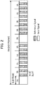
- FIG. 2 is a diagram depicting an example of a radio frame that is applied to the wireless communication system.
- the radio frame has a predetermined duration.
- the radio frame length is 10 ms in 5G, but may be shorter or longer than 10 ms.
- the radio frame is divided into a plurality of multiple sub-frames. In 5G, the sub-frame length is specified to 1 ms, and one radio frame is divided into 10 sub-frames.
- the sub-frame length and the number of divisions are not limited to the example in 5G.
- One sub-frame may be further divided into two or more slots (slot length: 500 ⁇ m). As indicated in FIG.
- each sub-frame of the radio frame is assigned to DL or UL.
- DL and UL are assigned such that four ULs continue after one DL. This assignment, however, is changeable.
- a slot in a sub-frame assigned to a UL is equally divided, where a reference signal (RS) is mapped to the first half portion, and a data signal (DS) is mapped to the latter half portion.
- RS reference signal
- DS data signal
- the reference signal is a known signal in the receiving station (base station 1), and is used to estimate a channel (called a "propagation path" or a "communication channel") of a wireless signal.
- the data signal is a signal generated by modulating and encoding the user data in accordance with a predetermined modulation and coding scheme (MCS).
- MCS modulation and coding scheme
- the wireless communication system has the following features in the uplink communication of data signals.
- the first feature is that in the wireless communication system according to the present embodiment, a configured grant (CG) is used.
- CG configured grant
- the frequency channels and slots that can be used for a CG are notified to the terminal 2 in advance, a different reference signal is provided for each terminal 2, and a CG is implemented by transmitting the reference signal along with the data signal (payload).
- a CG a communication delay caused by the procedure for the terminal to acquire a grant (communication permission) from the base station can be prevented.
- the second feature is that in the wireless communication system, wireless signals (reference signals and data signals) are transmitted from a plurality of terminals 2 using the same frequency domain and the same time domain (slot) based on the non-orthogonal multiple access.
- each terminal 2 transmits the wireless signals at a transmitting power specified by the base station 1, so that in the base station 1, a desired receiving power difference is generated between the terminals 2. If NOMA is used, the wait time of signal transmission can be decreased. However, in the base station 1, interference between each terminal 2 need be suppressed and cancelled.
- FIG. 3 is an explanatory diagram of power multiplexing and interference suppression and cancellation techniques.
- the diagram on the left schematically indicates the receiving power at the base station 1 of the wireless signals transmitted from terminals A, B and C, which is an example of the plurality of terminals 2.
- data signals received from the terminals A, B and C are superimposed with the receiving power at the base station 1 (superimposed signals).
- the power difference D1 between the receiving power of the terminal A and the receiving power of the terminal B, and the power difference D2 between the receiving power of the terminal B and the receiving power of the terminal C are at least the receiving power difference (required power difference ⁇ P) between terminals 2 at the base station 1, which is required for appropriate interference suppression and cancellation respectively.
- the base station 1 determines the propagation path characteristic based on the reference signal, and performs demodulation and decoding on the superimposed signals using this propagation path characteristic, whereby data from the terminal A can be acquired.
- the above mentioned wireless communication system which includes the UL communication using CG and NOMA, and the interference suppression and cancellation techniques (e.g. SIC) is called “simultaneous transmission access boosting low-latency (STABLE)" by the present inventor.
- the transmission (repetition) control method according to the present invention is also applicable to a wireless communication system to which NOMA other than STABLE is used.
- the successive interface cancellation (SIC) algorithm is used for the algorithm to perform the interference suppression and cancellation of signals from the terminal A from the superimposed signal.
- SIC is an algorithm that successively determines a signal for each terminal in descending order of the received signal strength indicator (RSSI), and eliminates the signal.
- the SIC algorithm uses an estimated value of the communication channel (propagation path) characteristic between a terminal 2, which uses a reference signal unique to the terminal 2, and the base station 1.
- the signal transmitted from a terminal 2 of which received signal strength is highest (terminal A) is reproduced (generated) (this signal is called a "replica signal") using the estimated value of the propagation path characteristic, and this signal is subtracted from the superimposed signal.
- this signal is called a "replica signal”
- demodulation and decoding using the propagation path characteristic are performed on the superimposed signal after the data signal from the terminal A is cancelled, whereby the data from the terminal B can be acquired.
- a replica signal of the data signal transmitted from the terminal B is generated using the SIC algorithm, and the replica signal is subtracted from the superimposed signal, whereby the interference caused by the data signal from the terminal B is cancelled (removed), and a data signal transmitted from the terminal C remains (see the diagram at the right in FIG. 3 ).
- demodulation and decoding using the propagation path characteristic, based on the reference signal from the terminal C are performed on the above signal, whereby the data from the terminal C can be acquired.
- each of the plurality of terminals 2 can perform repetition.
- "Repetition” refers to repeatedly transmitting a same signal successively at a predetermined cycle (e.g. in slot units).
- a signal transmitted from a terminal 2 by repetition is received and integrated by the base station 1. Adding the received signals by integration improves SNR, and thereby reception quality (SINR or propagation loss) improves.
- the code word length used for generating a data signal may be made uniform among the plurality of terminals 2.
- each of the plurality of terminals 2 may independently determine the code word length to be used, and performs the repetition in a state where different encoding rates coexist. The coexistence of different code word lengths occurs when the MCS to be used is different among the terminals 2, for example.
- the repetition is performed to increase the SNR by integrating the signals received by the repetition, and to improve the SINR.
- the plurality of terminals 2 may be arranged in ascending order of the propagation loss, and transmitting power is assigned to the plurality of terminals 2 such that the smaller the propagation loss the higher the receiving power at the base station.
- FIG. 4 is a diagram depicting an example of repetition.
- K-1 5 terminals 2 that perform the UL communication by NOMA.
- the identification information (user ID) of each of the five terminals 2 is “1", “2", “3", “4" and “5" respectively.
- the sequence of the numbers of the terminals "1” to "5" is in descending order of the propagation loss between each terminal and the base station 1.
- the code word lengths of terminals "1" to "5" are not the same.
- the code word lengths which the terminals "1" and "5" use for repetition are lengths that use four slots to transmit data signals for one cycle of repetition.
- the code word length which the terminal "2" uses for repetition is a length that uses two slots to transmit data signals for one cycle of repetition.
- the code word lengths which the terminals "3" and "4" use for repetition are the lengths that use one slot to transmit data signals for one cycle of repetition.
- FIG. 5 is a diagram depicting hardware configuration examples of the base station 1 and the terminal 2.
- the base station 1 includes M number of antennas 10 (10-1 to 10-M (M is a natural number)) indicated in FIG. 1A , a radio (wireless processing device) 1a, and a control device 1b.
- the control device 1b includes a processor 11, a storage device (memory) 12, an internal interface 13, and a network interface 14 to communicate with other base stations and the like.
- the processor 11 is also called a "central processing unit (CPU)" or a “microprocessor unit (MPU)".
- the processor 11 is not limited to a single processor, but may have a multi-processor configuration.
- a single physical CPU connected via a single socket may have a multi-core configuration.
- the processor 11 may include an arithmetic unit having various circuit configurations, such as a digital signal processor (DSP) and a graphics processing unit (GPU).
- DSP digital signal processor
- GPU graphics processing unit
- the processor 11 may be linked with an integrated circuit (IC) or other digital circuits or analog circuits.
- the integrated circuit can be an LSI, an application specific integrated circuit (ASIC), or a programmable logic device (PLD), for example.
- the PLD is a field programmable gate array (FPGA), for example.
- the processor 11 may be a micro-computer (MCU), a system-on-a-chip (SoC), a system LSI, or a chip set, for example.
- the processor 11 is an example of the controller (control unit).
- the storage device 12 stores an instruction sequence (computer program) executed by the processor 11, data processed by the processor 11, and the like.
- the internal interface (internal IF) 13 is a circuit to connect various peripheral devices to the processor 11.
- the network interface (NW-IF) 14 is a communication device for the base station 1 to access a network to which other base stations are connected.
- the network to which other base stations are connected is also called a "backhaul".
- a backhaul is a cable network based on optical communication.
- the radio 1a includes a transmitter that transmits wireless signals and a receiver that receives wireless signals, and is connected to the antennas 10 (10-1, ... 10-M).
- the radio 1a may have M number of transmitters and receivers, and the same number of antennas respectively.
- the terminal 2 includes the antenna 20, the radio (wireless processing device) 2a, and the control device 2b.
- the control device 2b includes a processor 21, a storage device (memory) 22, an internal interface (internal IF) 23, and a network interface (NW-IF) 24 to communicate with other base stations and the like.
- the processor 21, the storage device 22, the internal IF 23, the NW-IF 24 and the radio 2a have the same functions as the processor 11, the storage device 12, the internal IF 13, the NW-IF 14 and the radio 1a respectively.
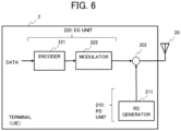
- FIG. 6 is a block diagram depicting a configuration example of the terminal.
- the terminal 2 operates as a device, including an RS unit 210 and a DS unit 220, by the processor 21 indicated in FIG. 5 executing the programs stored in the storage device 22.
- the RS unit 210 includes an RS generation unit 211.
- the RS generation unit 211 generates a reference signal.
- the DS unit 220 includes an encoding unit 221 (encoder) and a modulation unit 222 (modulator).
- the encoding unit 221 performs a predetermined error correction encoding for data that is inputted (user data).
- the error correction encoding is turbo encoding, for example, but may be a different encoding format. Before turbo encoding, a cyclic redundancy check (CRC), for example, may be performed.
- CRC cyclic redundancy check
- the modulation unit 222 generates data signals by performing digital modulation on the encoded data.
- the digital modulation method is, for example, quadrature amplitude modulation (QAM), phase shift keying (PSK) or the like.
- QAM quadrature amplitude modulation
- PSK phase shift keying
- the encoding and modulation methods are selected in accordance with the MCS that is set in the terminal 2.
- the terminal 2 further includes a multiplexer (multiplexing unit) 202.
- the output terminal of the multiplexer 202 is connected to the antenna 20.
- the multiplexer 202 switches to output the data signal, whereby the reference signal and the data signal for one slot are connected to the antenna 20.
- a signal block called the "cyclic prefix (CP)"
- CP cyclic prefix
- the data signals are generated so that the same data signal is transmitted from the base station 1 for a specified number of repetitions (N times). Alternately, a generated data signal may be reproduced and transmitted for a number of repetitions (N times).
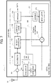
- FIG. 7 is a diagram depicting a configuration example of the base station 1.
- the base station 1 operates as the apparatus having the blocks indicated in FIG. 7 by the processor 11 of the base station 1 executing the programs stored in the storage device 12.
- the base station 1 includes the antenna 10, a demultiplexer 101, an RS unit 110 and a DS unit 120. Out of the signals received from the antenna 10, the demultiplexer 101, transmits a reference signal to an integration unit (integrator) 111 of the RS unit 110, and transmits a data signal to an integration unit (integrator) 121 of the DS unit 120 by a switch operation. At this time, the CPs attached to the reference signal and the data signal are cancelled.
- the integration unit 111 acquires a reference signal having sufficient receiving signal power by adding the reference signals received by the repetition.
- a communication channel estimation unit (path estimator) 112 calculates an estimated value of the communication channel characteristic (channel vector) using the integrated reference signal. This estimation value is used for demodulation processing by the demodulation unit 123 and for generating the replica signal.
- the DS unit 120 includes the integration unit 121, a replica cancellation unit (replica canceller, replica remover) 122, the demodulation unit 123, a decoding unit (decoder) 124 and a replica generation unit (replica generator) 126.
- the integration unit 121 adds the data signals repeatedly transmitted for a number of times of repetition Nk (N number of slots) assigned to the target terminal 2 (terminal k), so as to increase the SNR of the received signals, and thereby the SINR is improved.
- the replica cancellation unit 122 subtracts the replica signal, which was generated by the replica generation unit 126, from the integrated received signals (superimposed signals).
- the demodulation unit 123 separates the data signal of the target terminal 2 (terminal 2 of which transmitting power value is the maximum, out of the terminals which transmitted the superimposed signals) using an estimated value of the communication channel characteristic received from the communication channel estimation unit 112, and performs demodulation on the separated data signal.
- the decoding unit 124 decodes the data encoded by the encoding unit 221 of the terminal 2, and outputs the original data.
- the replica generation unit 126 includes an encoding unit (encoder) 127, a modulation unit (modulator) 128 and a multiplication unit 129.
- the encoding unit 127 and the modulation unit 128 perform the encoding and digital modulation, which were performed in the terminal 2, on the data outputted from the decoding unit 124.
- the multiplication unit 129 multiplies the modulated data by the estimated value of the communication channel characteristic between the target terminal 2 (terminal 2 which transmitted the decoded data) and the base station 1. Thereby the replica signal is generated.
- the replica signal is supplied to the replica cancellation unit 122.
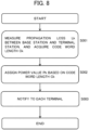
- FIG. 8 is a flow chart depicting a processing example at the base station 1.
- the processing in FIG. 8 is performed by the processor 11 (control device 1b) of the base station 1, for example.
- This processing is performed in the case where a plurality of terminals 2 transmit data to the base station 1, and is started at a timing when the base station 1 received, via a UL control channel, a transmission request for the data signal, which was transmitted from the terminal 2, for example.
- the start trigger is not limited to this.
- the input parameters to the processor 11 are as follows.
- the input parameters are stored in the storage device 12, for example. However, the input parameters may be stored at a location other than the storage device 12. Further, the processor 11 may acquire a part or all of the input parameters from a network.
- step S001 the processor 11 measures the propagation loss Lk between the base station 1 and each terminal 2, for K number of terminals 2 (terminal k: 0 ⁇ K-1), which performs UL communication using NOMA.
- the processor 11 also acquires the code word length C k (used for data transmission) which is transmitted from each of the K number of terminals 2.
- step S002 the processor 11 assigns the transmitting power value P k , based on the code word length C k , to each of the K number of terminals 2.
- the output parameter is as follows.
- the base station 1 transmits information including the output parameter to each of the plurality of terminals 2 via the DL control channel.
- the base station 1 can include the information that indicates the number of times of repeat, the repeat starting slot and the frequency channel used for the repeat. This information may be transmitted to the terminal 2 using a means other than the DL control channel.
- FIG. 9 is a flow chart exemplifying details of step S001 in FIG. 8 .
- the processor 11 instructs each terminal 2 to set the transmitting power in the transmitting power value p k,UE , and to transmit a control signal. This instruction is transmitted via the DL control channel, for example.
- step S012 the processor 11 measures the received signal strength r k,BS of the control signal which each terminal 2 transmitted with the transmitting power value p k,UE , in accordance with the above mentioned instruction.
- This control signal is transmitted via the UL control channel, for example.
- step S013 the processor 11 calculates the propagation loss L k between the terminal 2 and the base station 1 by subtracting the received signal strength r k,BS from the transmitting power value p k,UE .
- the base station 1 includes a plurality of antennas 10
- an average value of the propagation loss related to the received signal by each antenna 10 may be used as the propagation loss L k in step S013.
- step S014 the processor 11 acquires information (e.g. MCS) indicating the code word length C k , which each terminal 2 uses for the repetition and is included in the control signal, and stores this information in the storage device 22 or the like.
- information e.g. MCS
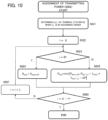
- FIG. 10 is a flow chart exemplifying details of the step S002 in FIG. 8 .
- the processor 11 determines k(i) as the terminal station ID when the code word length C k is in ascending order (in the order from the shorter length).
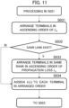
- FIG. 11 is a flow chart for describing details of step S021.
- the processor 11 arranges the K number of terminals 2 in ascending order of the shorter code word length C k .
- step S032 the processor 11 determines whether there are terminals having a same rank of two or more (terminals having the same code word length) among the K number of terminals 2, in the result of arranging the terminals in ascending order of the shorter code word length Ck. In other words, the processor 11 determines whether the same code word lengths C k exit among the code word lengths C k of the K number of terminals 2. Processing advances to step S033 if it is determined that the same code word lengths exist, or processing advances to step S034 if not.
- step S033 the terminals in the same rank are arranged in ascending order of the propagation loss L k .
- the transmitting power is assigned such that the received power at the base station 1 becomes high, whereby the SNR can be improved.
- step S034 k(i), which is the terminal ID, is assigned to each of the terminals k which are ranked in the state where there are no same rank.
- k(i) is a function which decreases as the value of i increases. In other words, the value of k(i) becomes a smaller value as the rank based on the code word length is higher.
- step S022 the processor 11 sets the value of the argument i to 0.
- step S023 the processor 11 determines whether the current value of i is 0 (minimum value of i). Processing advances to step S024 if it is determined that the value of i is 0, or processing advances to step S025 is not.
- step S024 the processor 11 sets the transmitting power value P k(i) to be assigned to the terminal k(i) to the maximum transmitting power P max,UE .
- a desired value lower than P max,UE may be used. Then processing advances to step S026.
- the processor 11 determines the transmitting power value P k(i) of the terminal k(i) to a smaller value out of the following first value and the second value.
- the second value becomes a value smaller than the first value.
- the second value becomes a value that is the required power difference ⁇ P or more, so that a sufficient power difference is acquired between terminals.
- step S026 the processor 11 determines whether the current value of i is K-1 (maximum value of i). The flow in FIG. 10 ends if it is determined that the value of i is K-1, or processing advances to step S027 if not.
- step S027 the value of i is incremented (1 is added to the current value of i), and processing returns to step S023.
- FIG. 12 is a diagram depicting an example of a modified repetition executed in the wireless communication system.
- the order of the terminals "1" to “5" is changed to "3" ⁇ "4" ⁇ “2" ⁇ “1” ⁇ "5" in the order of the shorter code word length, and transmitting power is assigned sequentially in descending order. Thereby the receiving power at the base station becomes higher in this order, and becomes the state indicated in FIG. 13 .
- the terminal "3" out of the terminals "1” to "5", the terminal "3", of which code word length is shortest, is ranked the highest.
- the code word length of the terminal "3” is the length of one slot, hence the delay required for demodulation and decoding of a signal from the terminal "3" is the length of one slot.
- the minimum delay from the start of repetition at a same timing (repetition start slot) of the terminals "1" to "5" to the start of demodulation and decoding of the signal can be shortened.
- appropriate delay control can be performed on the terminal "3" that perform repetition.
- the terminal "3" has a short code word length, and can acquire an appropriate demodulation and decoding result (required block error rate (BLER)) quickly by setting a high transmitting power, whereby the repetition of the terminal "3" can be quickly stopped.
- BLER block error rate
- FIG. 13 is a diagram depicting an experiment example related to the repetition using the wireless communication system according to the present embodiment.
- the environment of the experiment example is as follows.
- the user IDs are arranged in ascending order of the code word length (including the adjustment using propagation loss).
- the maximum transmitting power out of the plurality of terminals 2 that perform the repetition is assigned to the terminal 2 of which code word length is the shortest, hence the minimum delay required for demodulation and decoding of the signal from this terminal 2 is shortened.
- appropriate delay control can be performed for the terminals 2 which perform repetition.
- the wireless communication system includes a plurality of transmitting stations (terminals 2) which are connected to the wireless communication partner receiving station (base station 1) by non-orthogonal multiple access ( FIGS. 1A and 1B ).
- Each of the plurality of terminals 2 can transmit a same signal to the base station 1 successively for a predetermined number of times at a predetermined cycle (number of slots) by the repetition ( FIG. 4 ).
- the processor 11 also assigns to each of the plurality of terminals 2, the transmitting power for ensuring a required power difference ⁇ P which is required between the terminals 2, so that the shorter the code word length the higher the received power at the base station. Thereby the maximum receiving power, among the plurality of terminals 2, is assigned to the terminal 2 of which code word length is shortest.
- the minimum delay (required number of slots) which is required to start demodulation and decoding of this terminal 2 can be shortened, compared with the case of assigning higher transmitting power as the propagation loss is larger. As a result, appropriate delay control can be performed for the terminals 2 which perform the repetition.
- the processor 11 or the control device 1b assigns the transmitting power to at least two terminals 2, which are included in the plurality of terminals 2 and have the same code word length, so that the higher the receiving quality (the smaller the propagation loss) at the base station 1 the higher the receiving power (S083 in FIG. 11 , FIG. 10 ).
- the reception quality SINR or error rate
- the processor 11 or the control device 1b can acquire information that indicates the code word length which each of the plurality of the terminals 2 transmitted to the base station 1. For example, as indicated in FIG. 9 , the processor 11 or the control device 1b (base station 1) instructs the plurality of terminals 2 to transmit signals at a predetermined transmitting power (specified transmitting power) (S011). Then the processor 11 or the control device 1b can acquire information that indicates the code word length in the signal transmitted from each of the plurality of terminals 2 to the base station 1 in accordance with this instruction (S014).
- the processor 11 or the control device 1b can acquire the reception quality (propagation loss L k ) at the base station 1 of the signal transmitted to the base station 1.
- the acquisition of the code word length and the measurement of the propagation loss can be performed at the same time (efficiently).
- the acquisition of the code word length and the measurement of the propagation loss may be performed independently.
- the processor 11 or the control device 1b may perform the following steps. That is, the processor 11 or the control device 1b determines the ranks of the plurality of terminals 2, so that the shorter the code word length the higher the rank ( FIG. 11 ). Further, in the assignment of the transmitting power, the processor 11 or the control device 1b assigns the maximum transmitting power (P max,UE ) that is assignable, to the terminal k(0) of which rank is the highest among the plurality of terminals 2 so that the received power at the base station becomes maximum.
- P max,UE the maximum transmitting power
- the processor 11 or the control device 1b calculates the transmitting power that is assigned to each of the terminals other than the terminal k(0) at the highest rank, so that the required power difference ⁇ P of the receiving power at the base station is ensured, in a range of power that is lower than P max,UE (S025 in FIG. 10 ). Thereby a power difference appropriate for SIC can be provided to each terminal 2, and the level of transmitting power that can improve the SINR can be assigned to each terminal 2 of which rank is second or less.
- the processor 11 or the control device 1b can transmit information, which includes the transmitting power assigned to the plurality of terminals 2, to the plurality of terminals 2.
- This information can be transmitted via a UL control channel or the like (S003 in FIG. 8 ).
- the terminal 2 receives this information and can set the transmitting power used for the repetition.
- the terminal 2 may receive information which indicates a number of times of repetition, a repetition start timing and a frequency channel to be used, along with the information which indicates the transmitting power.
- each of the plurality of terminals 2 that perform the repetition is an example of the "first transmitting station", and the terminals 2 can receive information that indicates the transmitting power which is assigned to the plurality of terminals 2, so that the shorter the code word length of the terminal 2 the higher the receiving power at the base station 1.
- the terminal 2 can also execute: receiving an instruction from the base station 1, including the information indicating the code word length used for the repetition in the signal; and transmitting the signal in accordance with the instruction to the base station 1. At this time, the terminal 2 can transmit the signal in accordance with the instruction at the transmitting power specified by the base station 1.
- a processing step which was described based on the assumption that one device executes that step may be shared by a plurality of devices. Further, a processing step which was described based on the assumption that difference devices execute that step may be executed by one device.
- a kind of hardware configuration (server configuration) that implements each function may be freely changed.
- the present disclosure may also be implemented by supplying a computer program storing the functions described in the above embodiment to a computer, and one or more processors included in the computer reading and executing the program.
- This computer program may be provided to the computer by a non-transitory computer-readable storage medium that can be connected to the system bus of the computer, or may be provided to the computer via a network.
- the non-transitory computer-readable storage medium is an arbitrary type of disk, such as a magnetic disk (e.g. floppy (registered trademark) disk, hard disk drive (HDD)) and an optical disk (e.g.
- CD-ROM compact disc-read only memory
- DVD disk DVD disk
- Blu-ray disk a read only memory
- RAM random access memory
- EPROM erasable programmable read-only memory
- EEPROM electrically erasable programmable read-only memory
- magnetic card a magnetic card
- flash memory an optical card
- optical card an arbitrary type of medium suitable for storing electronic instructions.
Landscapes
- Engineering & Computer Science (AREA)
- Signal Processing (AREA)
- Computer Networks & Wireless Communication (AREA)
- Quality & Reliability (AREA)
- Mobile Radio Communication Systems (AREA)
Abstract
Description
- The present disclosure relates to a transmission control method and an information processing apparatus.
- The Third Generation Partnership Project (3GPP), a standardization organization that standardizes mobile communications, has set the coverage enhancement (the expansion of a communication range) as a subject in Release 17. In conference discussions, a technique to implement communications that satisfy desired communication requirements, regardless the distance from the base station, was considered, to include cases where the propagation loss between the base station and the terminal is large.
- A prior art related to the present disclosure is a technique to improve the signal to noise ratio (SNR) at a receiving station by repeatedly transmitting a same signal, and integrating the same signals at the receiving station (e.g. 3GPP TR 38.830, Study on NR coverage enhancements (Release 17), December 2020).
- Another prior art is a technique that allows a plurality of terminals, which can perform non-orthogonal multiple access (NOMA) to the base station, to transmit data in a same time zone using a same frequency band (e.g. M. Moriyama, T. Takizawa, M. Oodo, H. Tezuka, and F. Kojima, "Experimental Evaluation of a Novel Up-link NOMA System for IoT communication Equipping Repetition Transmission and Receive Diversity", IEICE Trans. Commun., Vol. E102 -B, No. 8, pp. 1467-1476).
- It is an object of the present disclosure to provide a technique that allows a transmitting station, which performs repetitive transmission, to control delays appropriately.
- An aspect of the present disclosure is a transmission control method for a plurality of transmitting stations which are connected to a wireless communication partner receiving station by non-orthogonal multiple access, and each of which is capable of transmitting a same signal to the receiving station by repetition for a predetermined number of times at a predetermined cycle, wherein an information processing apparatus executes: acquiring information indicating a code word length for each of the plurality of transmitting stations to use for the repetition; and assigning, to each of the plurality of transmitting stations, transmitting power for ensuring a receiving power difference at the receiving station which is required between transmitting stations, so that the shorter the code word length the higher the receiving power at the receiving station.
- Another aspect of the present disclosure is an information processing apparatus, including a controller, wherein for a plurality of transmitting stations which are connected to a wireless communication partner receiving station by non-orthogonal multiple access, and each of which is capable of transmitting a same signal to the receiving station by repetition for a predetermined number of times at a predetermined cycle, the controller executes: acquiring information indicating a code word length for each of the plurality of transmitting stations to use for the repetition; and assigning, to each of the plurality of transmitting stations, transmitting power for ensuring a receiving power difference at the receiving station which is required between transmitting stations, so that the shorter the code word length the higher the receiving power at the receiving station.
- Another aspect of the present disclosure is a transmission control method in a first transmitting station included in a plurality of transmitting stations which are connected to a wireless communication partner receiving station by non-orthogonal multiple access, and each of which is capable of transmitting a same signal to the receiving station by repetition for a predetermined number of times at a predetermined cycle, wherein the first transmitting station executes: transmitting a code word length used for the repetition to the receiving station; receiving information that indicates the transmitting power which is assigned based on the code word length to be used for the repetition; and performing the repetition using the transmitting power.
- Other aspect of the present disclosure may include a wireless communication system which includes the above mentioned plurality of transmitting stations and receiving station, a program which causes a computer to operate as the above mentioned transmitting stations, receiving station or information processing apparatus, and a non-transitory storage medium which records the above mentioned program.
- According to the present disclosure, good delay control can be performed for transmitting stations which perform the repetition transmission.
-
-
FIG. 1A is a diagram depicting a first configuration example of a wireless communication system, andFIG. 1B is a diagram depicting a second configuration example of the wireless communication system; -
FIG. 2 is a diagram depicting an example of a radio frame (wireless frame) that is applied to the wireless communication system; -
FIG. 3 is an explanatory diagram of power multiplexing, interference suppression and cancellation techniques; -
FIG. 4 is a diagram depicting an example of repetition in the wireless communication system; -
FIG. 5 is a diagram depicting hardware configuration example of a base station and a terminal; -
FIG. 6 is a block diagram depicting a configuration example of the terminal; -
FIG. 7 is a block diagram depicting a configuration example of the base station; -
FIG. 8 is a flow chart depicting a processing example in the base station; -
FIG. 9 is a flow chart exemplifying details of step S001 inFIG. 8 ; -
FIG. 10 is a flow chart depicting details of step S002 atFIG. 8 ; -
FIG. 11 is a flow chart depicting details of step S021 inFIG. 10 ; -
FIG. 12 is a diagram depicting an example of a modified repetition executed in the wireless communication system; and -
FIG. 13 is a diagram depicting an experiment example related to the repetition. -
FIG. 1A is a diagram depicting a first configuration example of a wireless communication system according to embodiment.FIG. 1B is a diagram depicting a second configuration example of the wireless communication system. The wireless communication system according to the first configuration example includes a base station (BS) 1 and a plurality of terminals 2 (#0 to #K-1, K is a natural number that includes 0), which communicate with thebase station 1 wirelessly. Thebase station 1 is an example of a receiving station, and the plurality ofterminals 2 are an example of a plurality of transmitting stations. - Each of the plurality of
terminals 2 is called a "user equipment (UE)". Each of the plurality ofterminals 2 includes anantenna 20, aradio 2a connected with theantenna 20, and acontrol device 2b connected with theradio 2a. Thecontrol device 2b acquires (receives) data from asensor 3 or the like. Thecontrol device 2b controls theradio 2a to transmit data signals or control signals to thebase station 1, or to receive control signals and the like from thebase station 1. Theradio 2a converts transmission target signals, including the data signals and control signals, into radio signals, and emits (transmits) the radio signals from theantenna 20. Theradio 2a also converts the radio signals received from theantenna 20 into signal format, which can be handled by thecontrol device 2b. A number ofantennas 20 may be one or two or more. Theterminal 2 may have two or more antennas, so that multiple-input and multiple-output (MIMO) communication is performed with thebase station 1. - The
base station 1 includes one or two ormore antennas 10, aradio 1a connected with theantenna 10, and acontrol device 1b connected with theradio 1a. Theradio 1a and thecontrol device 1b have the same functions as theradio 2a and thecontrol device 2b. Thecontrol device 1b can transmit data received from theterminal 2 to aserver 4 or the like. Thecontrol device 1b is an example of an information processing apparatus (computer). The information processing apparatus may be included in thebase station 1, or may be a terminal device (e.g. server) that is different from (independent from) thebase station 1. In other words, such a terminal device as a server may have a function to calculate a number of times of the repetition transmission to the plurality ofterminals 2 and the transmitting power that is used for each time, and to notify (transmit) the calculation result to eachterminal 2. - According to the wireless communication system, data acquired by each of the plurality of
terminals 2 from the sensor 3 (e.g. Internet of Things (IoT) data) can be stored on theserver 4 via thebase station 1. Further, the data from theserver 4 can be transmitted to each of theterminals 2 via thebase station 1. Theterminal 2 may be a fixed terminal or a mobile terminal. The mobile terminal may be a portable terminal or an onboard terminal. The onboard terminal may be a terminal used inside a vehicle, or a terminal installed in the vehicle. - As the second configuration example in
FIG. 1B indicates, abase station 1A, which includes at least two distributed base stations and acontrol device 1b, may be used instead of thebase station 1. A distributed base station includes theantenna 10 and theradio 1a, and is called a "remote radio head (RRH)" (radio unit). Thecontrol device 1b, to which at least two distributed base stations are connected, is called a "base band unit (BBU)" (signal processing unit). In the following, thebase station 1 having the first configuration example will be described. - In the first and second configuration examples, the
base station 1 and each of the plurality ofterminals 2 perform communication (transmission/reception of signals) using a downlink (DL) and an uplink (UL). DL is a line from thebase station 1 to theterminal 2, and includes a control channel (control CH) that is used for transmission (notification) of the control signals. UL, on the other hand, is a line from theterminal 2 to thebase station 1, and includes the control CH and a shared channel (shared CH) that is used for transmission of data (user data). The shared CH is also called a "data channel". - UL signals and DL signals are transmitted using a time domain assigned by the time division multiplexing.
FIG. 2 is a diagram depicting an example of a radio frame that is applied to the wireless communication system. InFIG. 2 , the radio frame has a predetermined duration. The radio frame length is 10 ms in 5G, but may be shorter or longer than 10 ms. The radio frame is divided into a plurality of multiple sub-frames. In 5G, the sub-frame length is specified to 1 ms, and one radio frame is divided into 10 sub-frames. The sub-frame length and the number of divisions, however, are not limited to the example in 5G. One sub-frame may be further divided into two or more slots (slot length: 500 µm). As indicated inFIG. 2 , each sub-frame of the radio frame is assigned to DL or UL. In the example inFIG. 2 , DL and UL are assigned such that four ULs continue after one DL. This assignment, however, is changeable. A slot in a sub-frame assigned to a UL is equally divided, where a reference signal (RS) is mapped to the first half portion, and a data signal (DS) is mapped to the latter half portion. However, the arrangement of the reference signal and the data signal in one slot is changeable as necessary. - The reference signal is a known signal in the receiving station (base station 1), and is used to estimate a channel (called a "propagation path" or a "communication channel") of a wireless signal. The data signal is a signal generated by modulating and encoding the user data in accordance with a predetermined modulation and coding scheme (MCS).
- The wireless communication system has the following features in the uplink communication of data signals. The first feature is that in the wireless communication system according to the present embodiment, a configured grant (CG) is used. As indicated in
FIG. 2 , in the UL communication, the frequency channels and slots that can be used for a CG are notified to theterminal 2 in advance, a different reference signal is provided for each terminal 2, and a CG is implemented by transmitting the reference signal along with the data signal (payload). By using a CG, a communication delay caused by the procedure for the terminal to acquire a grant (communication permission) from the base station can be prevented. - The second feature is that in the wireless communication system, wireless signals (reference signals and data signals) are transmitted from a plurality of
terminals 2 using the same frequency domain and the same time domain (slot) based on the non-orthogonal multiple access. In this case, each terminal 2 transmits the wireless signals at a transmitting power specified by thebase station 1, so that in thebase station 1, a desired receiving power difference is generated between theterminals 2. If NOMA is used, the wait time of signal transmission can be decreased. However, in thebase station 1, interference between each terminal 2 need be suppressed and cancelled. -
FIG. 3 is an explanatory diagram of power multiplexing and interference suppression and cancellation techniques. InFIG. 3 , the diagram on the left schematically indicates the receiving power at thebase station 1 of the wireless signals transmitted from terminals A, B and C, which is an example of the plurality ofterminals 2. In this example, data signals received from the terminals A, B and C are superimposed with the receiving power at the base station 1 (superimposed signals). The power difference D1 between the receiving power of the terminal A and the receiving power of the terminal B, and the power difference D2 between the receiving power of the terminal B and the receiving power of the terminal C are at least the receiving power difference (required power difference ΔP) betweenterminals 2 at thebase station 1, which is required for appropriate interference suppression and cancellation respectively. - The
base station 1 determines the propagation path characteristic based on the reference signal, and performs demodulation and decoding on the superimposed signals using this propagation path characteristic, whereby data from the terminal A can be acquired. The above mentioned wireless communication system, which includes the UL communication using CG and NOMA, and the interference suppression and cancellation techniques (e.g. SIC) is called "simultaneous transmission access boosting low-latency (STABLE)" by the present inventor. The transmission (repetition) control method according to the present invention, however, is also applicable to a wireless communication system to which NOMA other than STABLE is used. - For the algorithm to perform the interference suppression and cancellation of signals from the terminal A from the superimposed signal, the successive interface cancellation (SIC) algorithm is used. SIC is an algorithm that successively determines a signal for each terminal in descending order of the received signal strength indicator (RSSI), and eliminates the signal. The SIC algorithm uses an estimated value of the communication channel (propagation path) characteristic between a terminal 2, which uses a reference signal unique to the
terminal 2, and thebase station 1. In other words, in processing with the SIC algorithm, the signal transmitted from aterminal 2 of which received signal strength is highest (terminal A) is reproduced (generated) (this signal is called a "replica signal") using the estimated value of the propagation path characteristic, and this signal is subtracted from the superimposed signal. Thereby the interference by the data signal from the terminal A is cancelled (removed) from the superimposed signal (see the diagram at the center inFIG. 3 ). - Then demodulation and decoding using the propagation path characteristic, based on the reference signal from the terminal B, are performed on the superimposed signal after the data signal from the terminal A is cancelled, whereby the data from the terminal B can be acquired. Further, a replica signal of the data signal transmitted from the terminal B is generated using the SIC algorithm, and the replica signal is subtracted from the superimposed signal, whereby the interference caused by the data signal from the terminal B is cancelled (removed), and a data signal transmitted from the terminal C remains (see the diagram at the right in
FIG. 3 ). Then demodulation and decoding using the propagation path characteristic, based on the reference signal from the terminal C, are performed on the above signal, whereby the data from the terminal C can be acquired. - In the wireless communication system, each of the plurality of
terminals 2 can perform repetition. "Repetition" refers to repeatedly transmitting a same signal successively at a predetermined cycle (e.g. in slot units). A signal transmitted from aterminal 2 by repetition is received and integrated by thebase station 1. Adding the received signals by integration improves SNR, and thereby reception quality (SINR or propagation loss) improves. - In some cases during the repetition, the code word length used for generating a data signal (that is, the encoding rate) may be made uniform among the plurality of
terminals 2. On the other hand, each of the plurality ofterminals 2 may independently determine the code word length to be used, and performs the repetition in a state where different encoding rates coexist. The coexistence of different code word lengths occurs when the MCS to be used is different among theterminals 2, for example. - The repetition is performed to increase the SNR by integrating the signals received by the repetition, and to improve the SINR. For this, in some cases the plurality of
terminals 2 may be arranged in ascending order of the propagation loss, and transmitting power is assigned to the plurality ofterminals 2 such that the smaller the propagation loss the higher the receiving power at the base station. -
FIG. 4 is a diagram depicting an example of repetition. InFIG. 4 , it is assumed that there are five (K-1 = 5)terminals 2 that perform the UL communication by NOMA. The identification information (user ID) of each of the fiveterminals 2 is "1", "2", "3", "4" and "5" respectively. The sequence of the numbers of the terminals "1" to "5" is in descending order of the propagation loss between each terminal and thebase station 1. The code word lengths of terminals "1" to "5" are not the same. In the example inFIG. 4 , the code word lengths which the terminals "1" and "5" use for repetition are lengths that use four slots to transmit data signals for one cycle of repetition. The code word length which the terminal "2" uses for repetition is a length that uses two slots to transmit data signals for one cycle of repetition. The code word lengths which the terminals "3" and "4" use for repetition are the lengths that use one slot to transmit data signals for one cycle of repetition. - As indicated in
FIG. 4 , in the case where the code word length of a terminal located at an order lower than terminal "1", of which receiving power at the base station is highest (that is, in the case of the terminals "2", "3" and "4" in the example inFIG. 4 ), is shorter than the code word length of the terminal "1", the following problem occurs. That is, it takes four slots to receive the data signals from the terminal "1", hence the minimum delay to cancel the signals from the terminal "1" by generating a replica signal of the signal from the terminal "1" using SIC becomes four slots. However, in the reception of the four slots, each of the terminals "2", "3" and "4" has already completed reception to perform normal demodulation and decoding. Nonetheless, the wait time due to the minimum delay is generated for the terminal "1", and a long delay time is generated until the decoding results are received from these terminals. In the following, a wireless communication system and a transmission control method for the transmitting station in which at least the above mentioned problem can be solved will be described. -
FIG. 5 is a diagram depicting hardware configuration examples of thebase station 1 and theterminal 2. InFIG. 5 , thebase station 1 includes M number of antennas 10 (10-1 to 10-M (M is a natural number)) indicated inFIG. 1A , a radio (wireless processing device) 1a, and acontrol device 1b. Thecontrol device 1b includes aprocessor 11, a storage device (memory) 12, aninternal interface 13, and anetwork interface 14 to communicate with other base stations and the like. - The
processor 11 is also called a "central processing unit (CPU)" or a "microprocessor unit (MPU)". Theprocessor 11 is not limited to a single processor, but may have a multi-processor configuration. In theprocessor 11, a single physical CPU connected via a single socket may have a multi-core configuration. Further, theprocessor 11 may include an arithmetic unit having various circuit configurations, such as a digital signal processor (DSP) and a graphics processing unit (GPU). Theprocessor 11 may be linked with an integrated circuit (IC) or other digital circuits or analog circuits. The integrated circuit can be an LSI, an application specific integrated circuit (ASIC), or a programmable logic device (PLD), for example. The PLD is a field programmable gate array (FPGA), for example. Theprocessor 11 may be a micro-computer (MCU), a system-on-a-chip (SoC), a system LSI, or a chip set, for example. Theprocessor 11 is an example of the controller (control unit). - The
storage device 12 stores an instruction sequence (computer program) executed by theprocessor 11, data processed by theprocessor 11, and the like. The internal interface (internal IF) 13 is a circuit to connect various peripheral devices to theprocessor 11. - The network interface (NW-IF) 14 is a communication device for the
base station 1 to access a network to which other base stations are connected. The network to which other base stations are connected is also called a "backhaul". A backhaul is a cable network based on optical communication. - The
radio 1a includes a transmitter that transmits wireless signals and a receiver that receives wireless signals, and is connected to the antennas 10 (10-1, ... 10-M). Theradio 1a may have M number of transmitters and receivers, and the same number of antennas respectively. - In
FIG. 5 , theterminal 2 includes theantenna 20, the radio (wireless processing device) 2a, and thecontrol device 2b. Thecontrol device 2b includes aprocessor 21, a storage device (memory) 22, an internal interface (internal IF) 23, and a network interface (NW-IF) 24 to communicate with other base stations and the like. - The
processor 21, thestorage device 22, the internal IF 23, the NW-IF 24 and theradio 2a have the same functions as theprocessor 11, thestorage device 12, the internal IF 13, the NW-IF 14 and theradio 1a respectively. -
FIG. 6 is a block diagram depicting a configuration example of the terminal. Theterminal 2 operates as a device, including anRS unit 210 and aDS unit 220, by theprocessor 21 indicated inFIG. 5 executing the programs stored in thestorage device 22. TheRS unit 210 includes anRS generation unit 211. TheRS generation unit 211 generates a reference signal. - The
DS unit 220 includes an encoding unit 221 (encoder) and a modulation unit 222 (modulator). Theencoding unit 221 performs a predetermined error correction encoding for data that is inputted (user data). The error correction encoding is turbo encoding, for example, but may be a different encoding format. Before turbo encoding, a cyclic redundancy check (CRC), for example, may be performed. - The
modulation unit 222 generates data signals by performing digital modulation on the encoded data. The digital modulation method is, for example, quadrature amplitude modulation (QAM), phase shift keying (PSK) or the like. The encoding and modulation methods are selected in accordance with the MCS that is set in theterminal 2. - The
terminal 2 further includes a multiplexer (multiplexing unit) 202. The output terminal of themultiplexer 202 is connected to theantenna 20. After outputting the reference signal, themultiplexer 202 switches to output the data signal, whereby the reference signal and the data signal for one slot are connected to theantenna 20. In the respective previous stages of the reference signal and the data signal, a signal block, called the "cyclic prefix (CP)", may be set to compensate for the influence of the delay wave. In the case of the repetition, the data signals are generated so that the same data signal is transmitted from thebase station 1 for a specified number of repetitions (N times). Alternately, a generated data signal may be reproduced and transmitted for a number of repetitions (N times). -
FIG. 7 is a diagram depicting a configuration example of thebase station 1. Thebase station 1 operates as the apparatus having the blocks indicated inFIG. 7 by theprocessor 11 of thebase station 1 executing the programs stored in thestorage device 12. As indicated inFIG. 7 , thebase station 1 includes theantenna 10, ademultiplexer 101, anRS unit 110 and aDS unit 120. Out of the signals received from theantenna 10, thedemultiplexer 101, transmits a reference signal to an integration unit (integrator) 111 of theRS unit 110, and transmits a data signal to an integration unit (integrator) 121 of theDS unit 120 by a switch operation. At this time, the CPs attached to the reference signal and the data signal are cancelled. - The
integration unit 111 acquires a reference signal having sufficient receiving signal power by adding the reference signals received by the repetition. A communication channel estimation unit (path estimator) 112 calculates an estimated value of the communication channel characteristic (channel vector) using the integrated reference signal. This estimation value is used for demodulation processing by thedemodulation unit 123 and for generating the replica signal. - The
DS unit 120 includes theintegration unit 121, a replica cancellation unit (replica canceller, replica remover) 122, thedemodulation unit 123, a decoding unit (decoder) 124 and a replica generation unit (replica generator) 126. Theintegration unit 121 adds the data signals repeatedly transmitted for a number of times of repetition Nk (N number of slots) assigned to the target terminal 2 (terminal k), so as to increase the SNR of the received signals, and thereby the SINR is improved. - The
replica cancellation unit 122 subtracts the replica signal, which was generated by thereplica generation unit 126, from the integrated received signals (superimposed signals). Thedemodulation unit 123 separates the data signal of the target terminal 2 (terminal 2 of which transmitting power value is the maximum, out of the terminals which transmitted the superimposed signals) using an estimated value of the communication channel characteristic received from the communicationchannel estimation unit 112, and performs demodulation on the separated data signal. Thedecoding unit 124 decodes the data encoded by theencoding unit 221 of theterminal 2, and outputs the original data. - The
replica generation unit 126 includes an encoding unit (encoder) 127, a modulation unit (modulator) 128 and amultiplication unit 129. Theencoding unit 127 and themodulation unit 128 perform the encoding and digital modulation, which were performed in theterminal 2, on the data outputted from thedecoding unit 124. Themultiplication unit 129 multiplies the modulated data by the estimated value of the communication channel characteristic between the target terminal 2 (terminal 2 which transmitted the decoded data) and thebase station 1. Thereby the replica signal is generated. The replica signal is supplied to thereplica cancellation unit 122. -
FIG. 8 is a flow chart depicting a processing example at thebase station 1. The processing inFIG. 8 is performed by the processor 11 (control device 1b) of thebase station 1, for example. This processing is performed in the case where a plurality ofterminals 2 transmit data to thebase station 1, and is started at a timing when thebase station 1 received, via a UL control channel, a transmission request for the data signal, which was transmitted from theterminal 2, for example. The start trigger, however, is not limited to this. The input parameters to theprocessor 11 are as follows. - Terminal ID (user ID) k: k is a value in range from a minimum value "0" to a maximum value "K-1"
- Maximum transmitting power Pmax,UE: the allowable maximum value of the transmitting power that the
terminal 2 can use - Required power difference ΔP: receiving power difference between terminals at the base station, which is required to perform appropriate interference suppression and cancellation
- The input parameters are stored in the
storage device 12, for example. However, the input parameters may be stored at a location other than thestorage device 12. Further, theprocessor 11 may acquire a part or all of the input parameters from a network. - In step S001, the
processor 11 measures the propagation loss Lk between thebase station 1 and each terminal 2, for K number of terminals 2 (terminal k: 0 ~ K-1), which performs UL communication using NOMA. Theprocessor 11 also acquires the code word length Ck (used for data transmission) which is transmitted from each of the K number ofterminals 2. - In step S002, the
processor 11 assigns the transmitting power value Pk, based on the code word length Ck, to each of the K number ofterminals 2. At the point when step S003 ends, the output parameter is as follows. - Transmitting power Pk specified to each of the K number of terminals 2 (terminals having terminal ID: k = 0 to K-1)
- In step S003, the
base station 1 transmits information including the output parameter to each of the plurality ofterminals 2 via the DL control channel. At this time, in the information to be transmitted to theterminal 2, thebase station 1 can include the information that indicates the number of times of repeat, the repeat starting slot and the frequency channel used for the repeat. This information may be transmitted to theterminal 2 using a means other than the DL control channel. -
FIG. 9 is a flow chart exemplifying details of step S001 inFIG. 8 . In step S011, theprocessor 11 instructs each terminal 2 to set the transmitting power in the transmitting power value pk,UE, and to transmit a control signal. This instruction is transmitted via the DL control channel, for example. - In step S012, the
processor 11 measures the received signal strength rk,BS of the control signal which each terminal 2 transmitted with the transmitting power value pk,UE, in accordance with the above mentioned instruction. This control signal is transmitted via the UL control channel, for example. - In step S013, the
processor 11 calculates the propagation loss Lk between the terminal 2 and thebase station 1 by subtracting the received signal strength rk,BS from the transmitting power value pk,UE. In the case where thebase station 1 includes a plurality ofantennas 10, an average value of the propagation loss related to the received signal by eachantenna 10 may be used as the propagation loss Lk in step S013. - In step S014, the
processor 11 acquires information (e.g. MCS) indicating the code word length Ck, which each terminal 2 uses for the repetition and is included in the control signal, and stores this information in thestorage device 22 or the like. -
FIG. 10 is a flow chart exemplifying details of the step S002 inFIG. 8 . In step S021, theprocessor 11 determines k(i) as the terminal station ID when the code word length Ck is in ascending order (in the order from the shorter length). -
FIG. 11 is a flow chart for describing details of step S021. In step S031, theprocessor 11 arranges the K number ofterminals 2 in ascending order of the shorter code word length Ck. - In step S032, the
processor 11 determines whether there are terminals having a same rank of two or more (terminals having the same code word length) among the K number ofterminals 2, in the result of arranging the terminals in ascending order of the shorter code word length Ck. In other words, theprocessor 11 determines whether the same code word lengths Ck exit among the code word lengths Ck of the K number ofterminals 2. Processing advances to step S033 if it is determined that the same code word lengths exist, or processing advances to step S034 if not. - In step S033, the terminals in the same rank are arranged in ascending order of the propagation loss Lk. By increasing the rank of the
terminal 2 of which propagation loss is smaller, the transmitting power is assigned such that the received power at thebase station 1 becomes high, whereby the SNR can be improved. - In step S034, k(i), which is the terminal ID, is assigned to each of the terminals k which are ranked in the state where there are no same rank. k(i) is a function which decreases as the value of i increases. In other words, the value of k(i) becomes a smaller value as the rank based on the code word length is higher.
- An example will be described below. It is assumed, for example, that there are four terminals k (k = 0 to 3), and the values of the code word lengths Ck of these terminals k are as follows.
C0 = 5, C1 = 1, C2 = 2, C3 = 1 - Further, it is assumed that the propagation loss Lk of each terminal k is as follows.
L0 = 90, L1 = 80, L2 = 85, L3 = 75 - In the above example, the order based on Ck is C1 = C3, C2 and C0. Since C1 = C3, the propagation loss L1 and the propagation loss L3 thereof are compared. As a result, C3, of which propagation loss is lower (loss is higher), is placed at a higher rank than C1. Therefore the final order is C3, C1, C2 and C0. The value of k(i) of each terminal k = 0 to 3 becomes as follows, for example.
k(i=0) = 3, k(i=1) = 1, k(i=2) = 2, and k(i=3) = 0 - Referring back to
FIG. 10 , in step S022, theprocessor 11 sets the value of the argument i to 0. In step S023, theprocessor 11 determines whether the current value of i is 0 (minimum value of i). Processing advances to step S024 if it is determined that the value of i is 0, or processing advances to step S025 is not. - In step S024, the
processor 11 sets the transmitting power value Pk(i) to be assigned to the terminal k(i) to the maximum transmitting power Pmax,UE. Thereby the transmitting power of the terminal k(0), that is of the terminal k = 3, in the above example is set to the maximum transmitting power. Instead of the maximum transmitting power Pmax,UE, a desired value lower than Pmax,UE may be used. Then processing advances to step S026. - In the case where processing advances to step S025, the
processor 11 determines the transmitting power value Pk(i) of the terminal k(i) to a smaller value out of the following first value and the second value. - First value: maximum transmitting power Pmax,UE
- Second value: a value determined by subtracting the difference between the propagation loss Lk(i) and the propagation loss Lk(i-1) and the required power difference ΔP, from the power value Pk(i-1) of the terminal k(i-1)
- The second value becomes a value smaller than the first value. The second value becomes a value that is the required power difference ΔP or more, so that a sufficient power difference is acquired between terminals.
- In step S026, the
processor 11 determines whether the current value of i is K-1 (maximum value of i). The flow inFIG. 10 ends if it is determined that the value of i is K-1, or processing advances to step S027 if not. In step S027, the value of i is incremented (1 is added to the current value of i), and processing returns to step S023. In this way, the transmitting power value Pk(i) is determined for each terminal k (i = 1 to 3) indicated in the above mentioned example. Thereby the transmitting power is assigned to each terminal k, such that a power difference of at least the required power difference ΔP is ensured between the terminals k. -
FIG. 12 is a diagram depicting an example of a modified repetition executed in the wireless communication system. When the processing steps related to the flow charts inFIGS. 8 to 13 are performed on theterminals 2 of which terminal IDs are "1" to "5" indicated inFIG. 4 , the following operation is performed. That is, the terminals "1" to "5" are arranged in ascending order of the code word length Ck (including adjustment based on the propagation loss Lk) (steps S031 to S033), then the initial power value is assigned to the terminals "1" to "5" respectively (steps S023 to S027). Therefore the order of the terminals "1" to "5" is changed to "3" → "4" → "2" → "1" → "5" in the order of the shorter code word length, and transmitting power is assigned sequentially in descending order. Thereby the receiving power at the base station becomes higher in this order, and becomes the state indicated inFIG. 13 . Here, out of the terminals "1" to "5", the terminal "3", of which code word length is shortest, is ranked the highest. The code word length of the terminal "3" is the length of one slot, hence the delay required for demodulation and decoding of a signal from the terminal "3" is the length of one slot. In this way, according to the present embodiment, the minimum delay from the start of repetition at a same timing (repetition start slot) of the terminals "1" to "5" to the start of demodulation and decoding of the signal can be shortened. In other words, appropriate delay control can be performed on the terminal "3" that perform repetition. The terminal "3" has a short code word length, and can acquire an appropriate demodulation and decoding result (required block error rate (BLER)) quickly by setting a high transmitting power, whereby the repetition of the terminal "3" can be quickly stopped. -
FIG. 13 is a diagram depicting an experiment example related to the repetition using the wireless communication system according to the present embodiment. The environment of the experiment example is as follows. - Inter-site distance (ISD): 1732 m
- Non line-of-sight (NLOS) environment
- Maximum transmitting power: 23 dBm
- Number of antennas at base station 1: 2
- Randomly select three types corresponding to MCS = 1, 3, 5
- Error correcting code: low density parity check (LDPC)
- In the graph at the left side of
FIG. 13 , a plurality of user IDs (terminals 2) "1" to "6" are arranged in ascending order of the propagation loss. The ordinate of the graph is a number of slots that are required to start demodulation and decoding. - At the graph at the right side, on the other hand, the user IDs are arranged in ascending order of the code word length (including the adjustment using propagation loss). In this case, the maximum transmitting power out of the plurality of
terminals 2 that perform the repetition is assigned to theterminal 2 of which code word length is the shortest, hence the minimum delay required for demodulation and decoding of the signal from thisterminal 2 is shortened. Thus appropriate delay control can be performed for theterminals 2 which perform repetition. - The wireless communication system according to the present embodiment includes a plurality of transmitting stations (terminals 2) which are connected to the wireless communication partner receiving station (base station 1) by non-orthogonal multiple access (
FIGS. 1A and1B ). Each of the plurality ofterminals 2 can transmit a same signal to thebase station 1 successively for a predetermined number of times at a predetermined cycle (number of slots) by the repetition (FIG. 4 ). - The information processing apparatus included in the
base station 1, that is, acontrol device 1b including theprocessor 11, acquires information indicating a code word length for each of the plurality ofterminals 2 to use for the repetition (S014 inFIG. 9 ). Theprocessor 11 also assigns to each of the plurality ofterminals 2, the transmitting power for ensuring a required power difference ΔP which is required between theterminals 2, so that the shorter the code word length the higher the received power at the base station. Thereby the maximum receiving power, among the plurality ofterminals 2, is assigned to theterminal 2 of which code word length is shortest. Therefore the minimum delay (required number of slots) which is required to start demodulation and decoding of thisterminal 2 can be shortened, compared with the case of assigning higher transmitting power as the propagation loss is larger. As a result, appropriate delay control can be performed for theterminals 2 which perform the repetition. - In the embodiment, the
processor 11 or thecontrol device 1b assigns the transmitting power to at least twoterminals 2, which are included in the plurality ofterminals 2 and have the same code word length, so that the higher the receiving quality (the smaller the propagation loss) at thebase station 1 the higher the receiving power (S083 inFIG. 11 ,FIG. 10 ). By assigning the transmitting power so that the smaller the propagation loss of theterminal 2, the higher the receiving power at the base station, as described above, the reception quality (SINR or error rate) can be improved. - In the embodiment, the
processor 11 or thecontrol device 1b can acquire information that indicates the code word length which each of the plurality of theterminals 2 transmitted to thebase station 1. For example, as indicated inFIG. 9 , theprocessor 11 or thecontrol device 1b (base station 1) instructs the plurality ofterminals 2 to transmit signals at a predetermined transmitting power (specified transmitting power) (S011). Then theprocessor 11 or thecontrol device 1b can acquire information that indicates the code word length in the signal transmitted from each of the plurality ofterminals 2 to thebase station 1 in accordance with this instruction (S014). - In the embodiment, in accordance with the instruction, the
processor 11 or thecontrol device 1b can acquire the reception quality (propagation loss Lk) at thebase station 1 of the signal transmitted to thebase station 1. Thereby the acquisition of the code word length and the measurement of the propagation loss can be performed at the same time (efficiently). However, the acquisition of the code word length and the measurement of the propagation loss may be performed independently. - In the embodiment, the
processor 11 or thecontrol device 1b may perform the following steps. That is, theprocessor 11 or thecontrol device 1b determines the ranks of the plurality ofterminals 2, so that the shorter the code word length the higher the rank (FIG. 11 ). Further, in the assignment of the transmitting power, theprocessor 11 or thecontrol device 1b assigns the maximum transmitting power (Pmax,UE) that is assignable, to the terminal k(0) of which rank is the highest among the plurality ofterminals 2 so that the received power at the base station becomes maximum. Then theprocessor 11 or thecontrol device 1b calculates the transmitting power that is assigned to each of the terminals other than the terminal k(0) at the highest rank, so that the required power difference ΔP of the receiving power at the base station is ensured, in a range of power that is lower than Pmax,UE (S025 inFIG. 10 ). Thereby a power difference appropriate for SIC can be provided to each terminal 2, and the level of transmitting power that can improve the SINR can be assigned to eachterminal 2 of which rank is second or less. - In the embodiment, the
processor 11 or thecontrol device 1b can transmit information, which includes the transmitting power assigned to the plurality ofterminals 2, to the plurality ofterminals 2. This information can be transmitted via a UL control channel or the like (S003 inFIG. 8 ). Theterminal 2 receives this information and can set the transmitting power used for the repetition. Theterminal 2 may receive information which indicates a number of times of repetition, a repetition start timing and a frequency channel to be used, along with the information which indicates the transmitting power. - In the embodiment, each of the plurality of
terminals 2 that perform the repetition is an example of the "first transmitting station", and theterminals 2 can receive information that indicates the transmitting power which is assigned to the plurality ofterminals 2, so that the shorter the code word length of theterminal 2 the higher the receiving power at thebase station 1. - The
terminal 2 can also execute: receiving an instruction from thebase station 1, including the information indicating the code word length used for the repetition in the signal; and transmitting the signal in accordance with the instruction to thebase station 1. At this time, theterminal 2 can transmit the signal in accordance with the instruction at the transmitting power specified by thebase station 1. - The processing and means described in the present disclosure may be freely combined and used as long as technical inconsistency is not generated. A processing step which was described based on the assumption that one device executes that step may be shared by a plurality of devices. Further, a processing step which was described based on the assumption that difference devices execute that step may be executed by one device. In the computer system, a kind of hardware configuration (server configuration) that implements each function may be freely changed.
- The present disclosure may also be implemented by supplying a computer program storing the functions described in the above embodiment to a computer, and one or more processors included in the computer reading and executing the program. This computer program may be provided to the computer by a non-transitory computer-readable storage medium that can be connected to the system bus of the computer, or may be provided to the computer via a network. The non-transitory computer-readable storage medium is an arbitrary type of disk, such as a magnetic disk (e.g. floppy (registered trademark) disk, hard disk drive (HDD)) and an optical disk (e.g. CD-ROM, DVD disk, Blu-ray disk), a read only memory (ROM), a random access memory (RAM), an EPROM, an EEPROM, a magnetic card, a flash memory, an optical card, and an arbitrary type of medium suitable for storing electronic instructions.
Claims (20)
- A transmission control method for a plurality of transmitting stations (2) which are connected to a wireless communication partner receiving station (1) by non-orthogonal multiple access, and each of which is capable of transmitting a same signal to the receiving station (1) by repetition for a predetermined number of times at a predetermined cycle, wherein
an information processing apparatus (1b) executes:acquiring information indicating a code word length for each of the plurality of transmitting stations (2) to use for the repetition; andassigning, to each of the plurality of transmitting stations (2), transmitting power for ensuring a receiving power difference at the receiving station (1) which is required between transmitting stations (2), so that the shorter the code word length the higher the receiving power at the receiving station (1). - The transmission control method according to claim 1, wherein
the information processing apparatus (1b) assigns transmitting power to at least two transmitting stations (2) which are included in the plurality of transmitting stations (2) and have the same code word length, so that the higher the reception quality at the receiving station (1) the higher the receiving power at the receiving station (1). - The transmission control method according to claim 1 or 2, wherein
the information processing apparatus (1b) acquires information that indicates the code word length which each of the plurality of transmitting stations (2) transmitted to the receiving station (1). - The transmission control method according to claim 1 or 2, whereinthe information processing apparatus (1b) instructs the plurality of transmitting stations (2) to transmit signals at a predetermined transmitting power, andacquires information that indicates the code word length included in the signals which were transmitted from the plurality of transmitting stations (2) to the receiving station (1) in accordance with the instruction.
- The transmission control method according to claim 4, wherein
the information processing apparatus (1b) acquires the reception quality at the receiving station (1) of the signal transmitted to the receiving station (1). - The transmission control method according to any one of claims 1 to 5, wherein
the information processing apparatus (1b) determines the ranks of the plurality of transmitting stations (2) so that the shorter the code word length the higher the rank, and in the assignment of the transmitting power, the information processing apparatus (1b) assigns the maximum transmitting power that is assignable to the transmitting station (2) of which rank is the highest among the plurality of transmitting stations (2), and calculates the transmitting power that is assigned to each of the transmitting stations (2) other than the transmitting station (2) at the highest rank, so that the receiving power difference at the receiving station (1) is ensured in a range of power that is lower than the maximum transmitting power. - The transmission control method according to any one of claims 1 to 6, wherein
the information processing apparatus (1b) transmits information, including the transmitting power assigned to the plurality of transmitting stations (2), to the plurality of transmitting stations (2). - An information processing apparatus (1b) comprising a controller (11), whereinfor a plurality of transmitting stations (2) which are connected to a wireless communication partner receiving station (1) by non-orthogonal multiple access, and each of which is capable of transmitting a same signal to the receiving station (1) by repetition for a predetermined number of times at a predetermined cycle,the controller (11) is configured to execute:acquiring information indicating a code word length for each of the plurality of transmitting stations (2) to use for the repetition; andassigning, to each of the plurality of transmitting stations (2), transmitting power for ensuring a receiving power difference at the receiving station (1) which is required between transmitting stations (2), so that the shorter the code word length the higher the receiving power at the receiving station (1).
- The information processing apparatus (1b) according to claim 8, wherein
the controller (11) is configured to assign transmitting power to at least two transmitting stations (2) which are included in the plurality of transmitting stations (2) and have the same code word length, so that the higher the reception quality at the receiving station (1) the higher the receiving power at the receiving station (1). - The information processing apparatus (1b) according to claim 8 or 9, wherein
the controller (11) is configured to acquire information that indicates the code word length which each of the plurality of transmitting stations (2) transmitted to the receiving station (1). - The information processing apparatus (1b) according to claim 8 or 9, whereinthe controller (11) is configured to instruct the plurality of transmitting stations (2) to transmit signals at a predetermined transmitting power, andto acquire information that indicates the code word length included in the signals which were transmitted from the plurality of transmitting stations (2) to the receiving station (1) in accordance with the instruction.
- The information processing apparatus (1b) according to claim 11, wherein
the controller (11) is configured to acquire the reception quality at the receiving station (1) of the signal transmitted to the receiving station (1). - The information processing apparatus (1b) according to any one of claims 8 to 12, wherein
the controller (11) is configured to determine the ranks of the plurality of transmitting stations (2) so that the shorter the code word length the higher the rank, and in the assignment of the transmitting power, the controller (11) is configured to assign the maximum transmitting power that is assignable to the transmitting station (2) of which rank is the highest among the plurality of transmitting stations (2), and to calculate the transmitting power that is assigned to each of the transmitting stations (2) other than the transmitting station (2) at the highest rank, so that the receiving power difference at the receiving station (1) is ensured in a range of power that is lower than the maximum transmitting power. - The information processing apparatus (1b) according to any one of claims 8 to 13, wherein
the controller (11) is configured to transmit information, including the transmitting power assigned to the plurality of transmitting stations (2), to the plurality of transmitting stations (2). - The information processing apparatus (1b) according to any one of claims 8 to 14, wherein the information processing apparatus (1b) is included in the receiving station (1) .
- A transmission control method in a first transmitting station (2) included in a plurality of transmitting stations (2) which are connected to a wireless communication partner receiving station (1) by non-orthogonal multiple access, and each of which is capable of transmitting a same signal to the receiving station (1) by repetition for a predetermined number of times at a predetermined cycle, wherein
the first transmitting station (2) executes:transmitting a code word length used for the repetition to the receiving station (1);receiving information that indicates the transmitting power which is assigned based on the code word length to be used for the repetition; andperforming the repetition using the transmitting power. - The transmission control method according to claim 16, wherein
the first transmitting station (2) receives the information that indicates the transmitting power which is assigned to the plurality of transmitting stations (2), so that the shorter the code word length the higher the receiving power at the receiving station (1). - The transmission control method according to claim 16 or 17, wherein
the first transmitting station (2) further executes:receiving an instruction from the receiving station (1);including the information that indicates the code word length used for the repetition in a signal in accordance with the instruction; andtransmitting the signal in accordance with the instruction to the receiving station (1). - The transmission control method according to claim 18, wherein
the first transmitting station (2) transmits the signal in accordance with the instruction with the transmitting power specified by the receiving station (1). - The transmission control method according to any one of claims 16 to 19, wherein
the first transmitting station (2) receives information that indicates a start timing of the repetition, a frequency channel used for the repetition, and a number of times of the repetition.
Priority Applications (1)
| Application Number | Priority Date | Filing Date | Title |
|---|---|---|---|
| EP24206168.7A EP4468795A3 (en) | 2021-09-30 | 2022-09-29 | Transmission control method and information processing apparatus |
Applications Claiming Priority (1)
| Application Number | Priority Date | Filing Date | Title |
|---|---|---|---|
| JP2021161548A JP7667055B2 (en) | 2021-09-30 | 2021-09-30 | Transmission control method and information processing device |
Related Child Applications (2)
| Application Number | Title | Priority Date | Filing Date |
|---|---|---|---|
| EP24206168.7A Division EP4468795A3 (en) | 2021-09-30 | 2022-09-29 | Transmission control method and information processing apparatus |
| EP24206168.7A Division-Into EP4468795A3 (en) | 2021-09-30 | 2022-09-29 | Transmission control method and information processing apparatus |
Publications (2)
| Publication Number | Publication Date |
|---|---|
| EP4161166A1 true EP4161166A1 (en) | 2023-04-05 |
| EP4161166B1 EP4161166B1 (en) | 2024-11-20 |
Family
ID=83508822
Family Applications (2)
| Application Number | Title | Priority Date | Filing Date |
|---|---|---|---|
| EP22198855.3A Active EP4161166B1 (en) | 2021-09-30 | 2022-09-29 | Transmission control method and information processing apparatus |
| EP24206168.7A Pending EP4468795A3 (en) | 2021-09-30 | 2022-09-29 | Transmission control method and information processing apparatus |
Family Applications After (1)
| Application Number | Title | Priority Date | Filing Date |
|---|---|---|---|
| EP24206168.7A Pending EP4468795A3 (en) | 2021-09-30 | 2022-09-29 | Transmission control method and information processing apparatus |
Country Status (4)
| Country | Link |
|---|---|
| US (2) | US12432769B2 (en) |
| EP (2) | EP4161166B1 (en) |
| JP (1) | JP7667055B2 (en) |
| CN (1) | CN115915375A (en) |
Citations (3)
| Publication number | Priority date | Publication date | Assignee | Title |
|---|---|---|---|---|
| WO2018083601A1 (en) * | 2016-11-01 | 2018-05-11 | Akuon Peter Odero | Systems and methods for communication |
| WO2019178736A1 (en) * | 2018-03-20 | 2019-09-26 | 富士通株式会社 | Control information reception and transmission methods and, apparatuses, and communication system |
| WO2019195103A1 (en) * | 2018-04-04 | 2019-10-10 | Idac Holdings, Inc. | Methods of harq for noma |
Family Cites Families (20)
| Publication number | Priority date | Publication date | Assignee | Title |
|---|---|---|---|---|
| US5841768A (en) * | 1996-06-27 | 1998-11-24 | Interdigital Technology Corporation | Method of controlling initial power ramp-up in CDMA systems by using short codes |
| US6335922B1 (en) * | 1997-02-11 | 2002-01-01 | Qualcomm Incorporated | Method and apparatus for forward link rate scheduling |
| CA2424556C (en) * | 1997-04-17 | 2009-11-24 | Ntt Mobile Communications Network Inc. | Base station apparatus of mobile communication system |
| EP1040689B1 (en) * | 1998-07-16 | 2013-09-11 | Samsung Electronics Co., Ltd. | Processing packet data in mobile communication system |
| KR100401211B1 (en) * | 1998-09-03 | 2004-03-30 | 삼성전자주식회사 | Communication apparatus and method for reverse pilot signal in code division multiple access communication system |
| JP2000201101A (en) * | 1999-01-07 | 2000-07-18 | Fujitsu Ltd | Spreading communication system and its mobile device |
| USRE44010E1 (en) * | 1999-03-17 | 2013-02-19 | Interdigital Technology Corporation | Modular base station with variable communication capacity |
| JP2001320326A (en) * | 2000-03-03 | 2001-11-16 | Sony Corp | Communication system, communication method and communication device |
| US20090323641A1 (en) | 2006-11-10 | 2009-12-31 | Panasonic Corporation | Radio communication mobile station device and mcs selection method |
| US8245092B2 (en) * | 2008-11-03 | 2012-08-14 | Apple Inc. | Method for efficient control signaling of two codeword to one codeword transmission |
| KR101734948B1 (en) * | 2009-10-09 | 2017-05-12 | 삼성전자주식회사 | Method of Power Headroom Report, Resource Allocation and Power Control |
| CN102083187B (en) * | 2010-01-15 | 2013-02-20 | 电信科学技术研究院 | Method, system and device for transmitting uplink information and processing uplink information |
| JP5073770B2 (en) * | 2010-02-19 | 2012-11-14 | 株式会社エヌ・ティ・ティ・ドコモ | Mobile terminal apparatus, radio base station apparatus, and radio communication method |
| JP5484547B1 (en) * | 2012-11-07 | 2014-05-07 | ソフトバンクモバイル株式会社 | Transmission power control method and base station in base station of LTE radio communication system |
| EP3402257B1 (en) | 2016-01-07 | 2025-09-03 | Panasonic Intellectual Property Management Co., Ltd. | Communication device and communication method |
| JP2016195413A (en) * | 2016-06-20 | 2016-11-17 | 株式会社Nttドコモ | User terminal, radio base station, and radio communication method |
| WO2018208134A1 (en) * | 2017-05-12 | 2018-11-15 | 엘지전자 주식회사 | Method for controlling transmit power in wireless communication system and apparatus therefor |
| CN110504987B (en) * | 2019-07-30 | 2020-11-06 | 北京大学 | A resource allocation and access method in an open wireless channel |
| US11234199B2 (en) * | 2020-01-15 | 2022-01-25 | Ofinno, Llc | Power control procedure in a wireless network |
| CN112039347B (en) * | 2020-07-15 | 2021-08-06 | 上海交通大学 | A modular intelligent combined wind power converter and its control method |
-
2021
- 2021-09-30 JP JP2021161548A patent/JP7667055B2/en active Active
-
2022
- 2022-09-29 US US17/936,564 patent/US12432769B2/en active Active
- 2022-09-29 CN CN202211204140.1A patent/CN115915375A/en active Pending
- 2022-09-29 EP EP22198855.3A patent/EP4161166B1/en active Active
- 2022-09-29 EP EP24206168.7A patent/EP4468795A3/en active Pending
-
2025
- 2025-09-05 US US19/320,709 patent/US20260006632A1/en active Pending
Patent Citations (3)
| Publication number | Priority date | Publication date | Assignee | Title |
|---|---|---|---|---|
| WO2018083601A1 (en) * | 2016-11-01 | 2018-05-11 | Akuon Peter Odero | Systems and methods for communication |
| WO2019178736A1 (en) * | 2018-03-20 | 2019-09-26 | 富士通株式会社 | Control information reception and transmission methods and, apparatuses, and communication system |
| WO2019195103A1 (en) * | 2018-04-04 | 2019-10-10 | Idac Holdings, Inc. | Methods of harq for noma |
Non-Patent Citations (2)
| Title |
|---|
| "Experimental Evaluation of a Novel Up-link NOMA System for IoT communication Equipping Repetition Transmission and Receive Diversity", IEICE TRANS. COMMUN., vol. E102, no. 8, pages 1467 - 1476 |
| "Study on NR coverage enhancements (Release 17", 3GPP TR 38.830, December 2020 (2020-12-01) |
Also Published As
| Publication number | Publication date |
|---|---|
| EP4468795A2 (en) | 2024-11-27 |
| EP4161166B1 (en) | 2024-11-20 |
| JP2023051088A (en) | 2023-04-11 |
| JP7667055B2 (en) | 2025-04-22 |
| US20230096450A1 (en) | 2023-03-30 |
| US12432769B2 (en) | 2025-09-30 |
| CN115915375A (en) | 2023-04-04 |
| US20260006632A1 (en) | 2026-01-01 |
| EP4468795A3 (en) | 2024-12-18 |
Similar Documents
| Publication | Publication Date | Title |
|---|---|---|
| RU2501163C1 (en) | Base station (versions), transmission method (versions) and mobile communication system | |
| CN113826411B (en) | Base station, terminal and communication method | |
| JP5736298B2 (en) | Radio base station apparatus and interference control method | |
| KR20170016349A (en) | Devices and methods for facilitating non-orthogonal wireless communications | |
| EA026041B1 (en) | Wireless communication system, communication apparatus, wireless communication method and terminal apparatus | |
| CN103152091A (en) | Signal transmitting method, device and system | |
| US20200252165A1 (en) | Terminal and communication method | |
| WO2018028387A1 (en) | Data transmission method and device | |
| US20200153571A1 (en) | Segment Based Reference Signal | |
| JP2022512463A (en) | Precoding settings | |
| EP4161166B1 (en) | Transmission control method and information processing apparatus | |
| EP4161163A1 (en) | Transmission control method and information processing apparatus | |
| CN114830789B (en) | Downlink data receiving method, sending method, device, equipment and storage medium | |
| CN114374412B (en) | Receiving side device and wireless communication method | |
| KR20210094090A (en) | Space-Time Block Codes for Quasi-Orthogonal Multiple Access-based WLAN Systems | |
| CN112583534A (en) | Method for sending and receiving signaling, network equipment and terminal | |
| US20240007150A1 (en) | Telecommunication method for iterative reception and corresponding devices | |
| CN114375059B (en) | Base station and communication method | |
| CN115152304A (en) | Data transmission method and device | |
| WO2019192719A1 (en) | Message and rate based user grouping in non-orthogonal multiple access (noma) networks | |
| JP7262411B2 (en) | Receiving device, transmitting device, communication method, and program | |
| RU2782241C1 (en) | Data transmission method and communication device | |
| JP2023050835A (en) | Information processing device, transmitting device, and method | |
| CN121308906A (en) | A communication method and apparatus |
Legal Events
| Date | Code | Title | Description |
|---|---|---|---|
| PUAI | Public reference made under article 153(3) epc to a published international application that has entered the european phase |
Free format text: ORIGINAL CODE: 0009012 |
|
| STAA | Information on the status of an ep patent application or granted ep patent |
Free format text: STATUS: REQUEST FOR EXAMINATION WAS MADE |
|
| 17P | Request for examination filed |
Effective date: 20220929 |
|
| AK | Designated contracting states |
Kind code of ref document: A1 Designated state(s): AL AT BE BG CH CY CZ DE DK EE ES FI FR GB GR HR HU IE IS IT LI LT LU LV MC MK MT NL NO PL PT RO RS SE SI SK SM TR |
|
| GRAP | Despatch of communication of intention to grant a patent |
Free format text: ORIGINAL CODE: EPIDOSNIGR1 |
|
| GRAP | Despatch of communication of intention to grant a patent |
Free format text: ORIGINAL CODE: EPIDOSNIGR1 |
|
| STAA | Information on the status of an ep patent application or granted ep patent |
Free format text: STATUS: GRANT OF PATENT IS INTENDED |
|
| INTG | Intention to grant announced |
Effective date: 20240614 |
|
| RIC1 | Information provided on ipc code assigned before grant |
Ipc: H04W 52/42 20090101ALI20240531BHEP Ipc: H04W 52/34 20090101AFI20240531BHEP |
|
| GRAS | Grant fee paid |
Free format text: ORIGINAL CODE: EPIDOSNIGR3 |
|
| GRAA | (expected) grant |
Free format text: ORIGINAL CODE: 0009210 |
|
| STAA | Information on the status of an ep patent application or granted ep patent |
Free format text: STATUS: THE PATENT HAS BEEN GRANTED |
|
| AK | Designated contracting states |
Kind code of ref document: B1 Designated state(s): AL AT BE BG CH CY CZ DE DK EE ES FI FR GB GR HR HU IE IS IT LI LT LU LV MC MK MT NL NO PL PT RO RS SE SI SK SM TR |
|
| REG | Reference to a national code |
Ref country code: GB Ref legal event code: FG4D |
|
| P01 | Opt-out of the competence of the unified patent court (upc) registered |
Free format text: CASE NUMBER: APP_57265/2024 Effective date: 20241019 |
|
| REG | Reference to a national code |
Ref country code: CH Ref legal event code: EP |
|
| REG | Reference to a national code |
Ref country code: DE Ref legal event code: R096 Ref document number: 602022007887 Country of ref document: DE |
|
| REG | Reference to a national code |
Ref country code: IE Ref legal event code: FG4D |
|
| REG | Reference to a national code |
Ref country code: LT Ref legal event code: MG9D |
|
| REG | Reference to a national code |
Ref country code: NL Ref legal event code: MP Effective date: 20241120 |
|
| PG25 | Lapsed in a contracting state [announced via postgrant information from national office to epo] |
Ref country code: HR Free format text: LAPSE BECAUSE OF FAILURE TO SUBMIT A TRANSLATION OF THE DESCRIPTION OR TO PAY THE FEE WITHIN THE PRESCRIBED TIME-LIMIT Effective date: 20241120 Ref country code: PT Free format text: LAPSE BECAUSE OF FAILURE TO SUBMIT A TRANSLATION OF THE DESCRIPTION OR TO PAY THE FEE WITHIN THE PRESCRIBED TIME-LIMIT Effective date: 20250320 Ref country code: IS Free format text: LAPSE BECAUSE OF FAILURE TO SUBMIT A TRANSLATION OF THE DESCRIPTION OR TO PAY THE FEE WITHIN THE PRESCRIBED TIME-LIMIT Effective date: 20250320 |
|
| PG25 | Lapsed in a contracting state [announced via postgrant information from national office to epo] |
Ref country code: NL Free format text: LAPSE BECAUSE OF FAILURE TO SUBMIT A TRANSLATION OF THE DESCRIPTION OR TO PAY THE FEE WITHIN THE PRESCRIBED TIME-LIMIT Effective date: 20241120 Ref country code: FI Free format text: LAPSE BECAUSE OF FAILURE TO SUBMIT A TRANSLATION OF THE DESCRIPTION OR TO PAY THE FEE WITHIN THE PRESCRIBED TIME-LIMIT Effective date: 20241120 |
|
| REG | Reference to a national code |
Ref country code: AT Ref legal event code: MK05 Ref document number: 1744685 Country of ref document: AT Kind code of ref document: T Effective date: 20241120 |
|
| PG25 | Lapsed in a contracting state [announced via postgrant information from national office to epo] |
Ref country code: BG Free format text: LAPSE BECAUSE OF FAILURE TO SUBMIT A TRANSLATION OF THE DESCRIPTION OR TO PAY THE FEE WITHIN THE PRESCRIBED TIME-LIMIT Effective date: 20241120 |
|
| PG25 | Lapsed in a contracting state [announced via postgrant information from national office to epo] |
Ref country code: ES Free format text: LAPSE BECAUSE OF FAILURE TO SUBMIT A TRANSLATION OF THE DESCRIPTION OR TO PAY THE FEE WITHIN THE PRESCRIBED TIME-LIMIT Effective date: 20241120 |
|
| PG25 | Lapsed in a contracting state [announced via postgrant information from national office to epo] |
Ref country code: NO Free format text: LAPSE BECAUSE OF FAILURE TO SUBMIT A TRANSLATION OF THE DESCRIPTION OR TO PAY THE FEE WITHIN THE PRESCRIBED TIME-LIMIT Effective date: 20250220 |
|
| PG25 | Lapsed in a contracting state [announced via postgrant information from national office to epo] |
Ref country code: LV Free format text: LAPSE BECAUSE OF FAILURE TO SUBMIT A TRANSLATION OF THE DESCRIPTION OR TO PAY THE FEE WITHIN THE PRESCRIBED TIME-LIMIT Effective date: 20241120 Ref country code: GR Free format text: LAPSE BECAUSE OF FAILURE TO SUBMIT A TRANSLATION OF THE DESCRIPTION OR TO PAY THE FEE WITHIN THE PRESCRIBED TIME-LIMIT Effective date: 20250221 Ref country code: AT Free format text: LAPSE BECAUSE OF FAILURE TO SUBMIT A TRANSLATION OF THE DESCRIPTION OR TO PAY THE FEE WITHIN THE PRESCRIBED TIME-LIMIT Effective date: 20241120 |
|
| PG25 | Lapsed in a contracting state [announced via postgrant information from national office to epo] |
Ref country code: PL Free format text: LAPSE BECAUSE OF FAILURE TO SUBMIT A TRANSLATION OF THE DESCRIPTION OR TO PAY THE FEE WITHIN THE PRESCRIBED TIME-LIMIT Effective date: 20241120 |
|
| PG25 | Lapsed in a contracting state [announced via postgrant information from national office to epo] |
Ref country code: RS Free format text: LAPSE BECAUSE OF FAILURE TO SUBMIT A TRANSLATION OF THE DESCRIPTION OR TO PAY THE FEE WITHIN THE PRESCRIBED TIME-LIMIT Effective date: 20250220 |
|
| PG25 | Lapsed in a contracting state [announced via postgrant information from national office to epo] |
Ref country code: SM Free format text: LAPSE BECAUSE OF FAILURE TO SUBMIT A TRANSLATION OF THE DESCRIPTION OR TO PAY THE FEE WITHIN THE PRESCRIBED TIME-LIMIT Effective date: 20241120 |
|
| PG25 | Lapsed in a contracting state [announced via postgrant information from national office to epo] |
Ref country code: DK Free format text: LAPSE BECAUSE OF FAILURE TO SUBMIT A TRANSLATION OF THE DESCRIPTION OR TO PAY THE FEE WITHIN THE PRESCRIBED TIME-LIMIT Effective date: 20241120 |
|
| PG25 | Lapsed in a contracting state [announced via postgrant information from national office to epo] |
Ref country code: EE Free format text: LAPSE BECAUSE OF FAILURE TO SUBMIT A TRANSLATION OF THE DESCRIPTION OR TO PAY THE FEE WITHIN THE PRESCRIBED TIME-LIMIT Effective date: 20241120 |
|
| PG25 | Lapsed in a contracting state [announced via postgrant information from national office to epo] |
Ref country code: RO Free format text: LAPSE BECAUSE OF FAILURE TO SUBMIT A TRANSLATION OF THE DESCRIPTION OR TO PAY THE FEE WITHIN THE PRESCRIBED TIME-LIMIT Effective date: 20241120 |
|
| PG25 | Lapsed in a contracting state [announced via postgrant information from national office to epo] |
Ref country code: SK Free format text: LAPSE BECAUSE OF FAILURE TO SUBMIT A TRANSLATION OF THE DESCRIPTION OR TO PAY THE FEE WITHIN THE PRESCRIBED TIME-LIMIT Effective date: 20241120 |
|
| PG25 | Lapsed in a contracting state [announced via postgrant information from national office to epo] |
Ref country code: CZ Free format text: LAPSE BECAUSE OF FAILURE TO SUBMIT A TRANSLATION OF THE DESCRIPTION OR TO PAY THE FEE WITHIN THE PRESCRIBED TIME-LIMIT Effective date: 20241120 |
|
| PG25 | Lapsed in a contracting state [announced via postgrant information from national office to epo] |
Ref country code: IT Free format text: LAPSE BECAUSE OF FAILURE TO SUBMIT A TRANSLATION OF THE DESCRIPTION OR TO PAY THE FEE WITHIN THE PRESCRIBED TIME-LIMIT Effective date: 20241120 |
|
| REG | Reference to a national code |
Ref country code: DE Ref legal event code: R097 Ref document number: 602022007887 Country of ref document: DE |
|
| PG25 | Lapsed in a contracting state [announced via postgrant information from national office to epo] |
Ref country code: SE Free format text: LAPSE BECAUSE OF FAILURE TO SUBMIT A TRANSLATION OF THE DESCRIPTION OR TO PAY THE FEE WITHIN THE PRESCRIBED TIME-LIMIT Effective date: 20241120 |
|
| PLBE | No opposition filed within time limit |
Free format text: ORIGINAL CODE: 0009261 |
|
| STAA | Information on the status of an ep patent application or granted ep patent |
Free format text: STATUS: NO OPPOSITION FILED WITHIN TIME LIMIT |
|
| REG | Reference to a national code |
Ref country code: DE Ref legal event code: R084 Ref document number: 602022007887 Country of ref document: DE |
|
| PGFP | Annual fee paid to national office [announced via postgrant information from national office to epo] |
Ref country code: DE Payment date: 20250805 Year of fee payment: 4 |
|
| PGFP | Annual fee paid to national office [announced via postgrant information from national office to epo] |
Ref country code: FR Payment date: 20250808 Year of fee payment: 4 |
|
| 26N | No opposition filed |
Effective date: 20250821 |