EP4161136A1 - Increased uplink capacity for campus networks via tdd interference mitigation - Google Patents
Increased uplink capacity for campus networks via tdd interference mitigation Download PDFInfo
- Publication number
- EP4161136A1 EP4161136A1 EP21200124.2A EP21200124A EP4161136A1 EP 4161136 A1 EP4161136 A1 EP 4161136A1 EP 21200124 A EP21200124 A EP 21200124A EP 4161136 A1 EP4161136 A1 EP 4161136A1
- Authority
- EP
- European Patent Office
- Prior art keywords
- uplink
- interference
- served
- ues
- isolation
- Prior art date
- Legal status (The legal status is an assumption and is not a legal conclusion. Google has not performed a legal analysis and makes no representation as to the accuracy of the status listed.)
- Granted
Links
Images

Classifications
-
- H—ELECTRICITY
- H04—ELECTRIC COMMUNICATION TECHNIQUE
- H04W—WIRELESS COMMUNICATION NETWORKS
- H04W28/00—Network traffic management; Network resource management
- H04W28/02—Traffic management, e.g. flow control or congestion control
- H04W28/0231—Traffic management, e.g. flow control or congestion control based on communication conditions
- H04W28/0236—Traffic management, e.g. flow control or congestion control based on communication conditions radio quality, e.g. interference, losses or delay
-
- H—ELECTRICITY
- H04—ELECTRIC COMMUNICATION TECHNIQUE
- H04W—WIRELESS COMMUNICATION NETWORKS
- H04W28/00—Network traffic management; Network resource management
- H04W28/02—Traffic management, e.g. flow control or congestion control
- H04W28/0205—Traffic management, e.g. flow control or congestion control at the air interface
-
- H—ELECTRICITY
- H04—ELECTRIC COMMUNICATION TECHNIQUE
- H04W—WIRELESS COMMUNICATION NETWORKS
- H04W28/00—Network traffic management; Network resource management
- H04W28/02—Traffic management, e.g. flow control or congestion control
- H04W28/0231—Traffic management, e.g. flow control or congestion control based on communication conditions
Definitions
- This invention relates to systems and methods for mitigating downlink to uplink interference and uplink to downlink interference in a Time Division Duplex (TDD) communications system.
- TDD Time Division Duplex
- Campus networks are a new development within the ecosystem of mobile networks. Current networks have been designed and deployed for offering services to the public, especially end customers. In the future, there is the possibility to augment the list of offered services by offering private networks to business customers such as, for example, Campus networks.
- a Campus network can be seen as a dedicated small-scale deployment of the exiting large-scale public networks. However, there are several differences when comparing them in detail. One of them is related to the type of data traffic. In public networks, most data traffic flows from the Internet towards the end customer (downlink), whereas there is little traffic in the opposite direction (uplink). This is especially the case for video streaming services. Campus networks are often used for industrial services, where different types of traffic dominate. In general, industrial traffic is not dominated by downlink traffic. In many cases even uplink traffic dominates. For example, cameras can transmit several video streams in uplink.
- a Campus network can be implemented via the most recent mobile radio network technology, 5G.
- 5G In the main 5G frequency band at 3.x GHz, Time Division Duplex (TDD) is applied.
- TDD Time Division Duplex
- uplink and downlink transmissions take place in the same frequency band by switching in time domain.
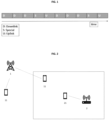
- FIG. 1 illustrates an example of a Time Division Duplex (TDD) frame structure.
- TDD Time Division Duplex
- the special slot guarantees a time-wise separation from downlink to uplink, such that no downlink signals are present at times of uplink transmission. Switching from uplink to downlink does not require this (due to lower power of uplink signals compared to downlink).
- TDD systems offer the advantage of a flexible configuration of the number of uplink and downlink slots. For the mentioned applications with high uplink requirements, it would therefore be possible to configure a high number of uplink slots and provide high uplink capacity.
- TDD systems transmit and receive on the same or neighbouring frequency band results in four interference scenarios:
- Campus networks are intended to serve industrial applications which often require a higher UL capacity than typical consumer applications served by public networks. This means that it may be necessary to apply, in Campus networks, other TDD frame structures that have more UL slots than the default frame structure used by the public networks on the adjacent frequency bands.
- a first communications network comprising a first BS and second communications network comprising a second BS, both within the same as well as in neighbouring bands, can operate at different TDD frame structures and thus use more downlink slots.
- a method for mitigating downlink, DL, to uplink, UL, interference in a Time Division Duplex, TDD, communications system comprising: a first communications network comprising a first Base Station, BS, and one or more user equipment, UEs, served by the first BS; and second communications network comprising a second BS, one or more user equipment, UEs, served by the second BS and a network Operation and Maintenance, O&M, entity, wherein the second BS is physically isolated from the first BS in terms of radio propagation.
- the method comprises the steps of: transmitting, by the first BS towards one or more UEs served by the first BS, information on a first frequency band, and receiving, by the second BS from one or more UEs served by the second BS, information on UL time slots in a second frequency band; measuring, by the second BS, a level of isolation from the first BS by: determining, by the second BS, UL time slots that are potentially affected by DL to UL interference, stopping transmission, by the second BS, of UL scheduling grants for the UL time slots that are potentially affected by interference, such that the one or more UEs served by the second BS do not transmit information during predetermined intervals in the UL time slots that are potentially affected by downlink to uplink interference, measuring a level of interference received within the uplink time slots potentially affected by downlink to uplink interference, and calculating the level of isolation based on the measured level of interference of the uplink time slots and an expected level of interference of the uplink time slots; determining, by the second BS, if
- the method may further comprise: determining, by the second BS, whether the measured level of isolation has been critical more than a predetermined period of time and, in case that it has been critical more than a predetermined period of time, performing the following steps: informing, by the second BS to the O&M entity, that the measured level of isolation has been critical for more than a predetermined period of time; and stopping use of the one or more interfered uplink time slots until the measured level of isolation becomes not critical.
- the expected level of interference is a level of interference as measured during installation of the second communications network and/or second BS or is predetermined.
- the second BS after determining, by the second BS, that the measured level of isolation has been critical for more than a predetermined period of time may further comprise: sending, by the second BS, a message towards the first BS, wherein the message comprises an indication to: reduce power on selected beams or apply slot blanking.
- the first frequency band and the second frequency band may be the same frequency band.
- the first frequency band and the second frequency band may be adjacent frequency bands.
- determining, by the second BS, uplink time slots that are potentially affected by downlink to uplink interference may further comprise: if the second BS has knowledge of TDD frame configuration information and start time information of the TDD frame of the first BS: checking, by the second BS, if the uplink time slots of the first BS and the second BS are not aligned, and if they are not aligned, determining, by the second BS, which uplink time slots are potentially affected by downlink to uplink interference, if the BS does not have knowledge of TDD frame configuration information and start time information of the TDD frame: determining, by the second BS, that all uplink time slots are potentially affected by downlink to uplink interference.
- a method for mitigating uplink to downlink interference in a Time Division Duplex, TDD, communications system comprising: a first communications network comprising a first Base Station, BS, and one or more user equipment, UEs, served by the first BS; a second communications network comprising a second BS and one or more user equipments, UEs, served by the second BS.
- the method comprises the steps of: receiving, by at least one UE served by the first BS, from the first BS, information on a first frequency band, and transmitting, by at least one UE, served by the second BS, to the second BS, information on a second frequency band; continuously checking, by the first BS, information feedback by the one or more UEs; determining, by the first BS, based on the feedback information, for each UE served by the first BS whether the UE is subject to uplink to downlink interference; determining, by the first BS, which uplink time slots are potentially subject to uplink to downlink interference by detecting whether the first BS and the one or more UEs served by the first BS, are not aligned with the second BS and the one or more UEs served by the second BS, wherein it is determined that they are not aligned if a UE served by the first BS is receiving in a downlink time slot and a UE served by the second BS is transmitting in an uplink time slot or
- optimizing the future usage of the slots may comprise: scheduling, by the first BS, slots that are potentially interfered to one or more UEs that are not subject to uplink to downlink interference; and scheduling, by the first BS, slots that are not potentially subject to uplink to downlink interference to one or more UEs that are subject to uplink to downlink interference.
- the first frequency band and the second frequency band may be the same frequency band.
- the first frequency band and the second frequency band may be adjacent frequency bands.
- the information feedback by the one or more UEs are: acknowledgments, ACKs, and/or negative acknowledgements, NACKs, referring to previous transmissions from the first BS to the at least one UE.
- a Time Division Duplex, TDD, communications system for mitigating downlink, DL, to uplink, UL, interference
- the communications system comprising: a first communications network comprising a first Base Station, BS, and one or more user equipment, UEs, served by the first BS; and second communications network comprising a second BS, one or more user equipment, UEs, served by the second BS and a network Operation and Maintenance, O&M, entity, wherein the second BS is physically isolated from the first BS in terms of radio propagation, wherein: the first BS is configured to transmit towards one or more UEs served by the first BS, information on a first frequency band, and the second BS is configured to receive from one or more UEs served by the second BS, information on UL time slots in a second frequency band; the second BS is configured to measure, a level of isolation by being configured to: determine UL time slots that are potentially affected by DL to UL interference, stop transmission of
- a Time Division Duplex, TDD, communications system for mitigating uplink to downlink interference in, the communications system comprising: a first communications network comprising a first Base Station, BS, and one or more user equipment, UEs, served by the first BS; a second communications network comprising a second BS and one or more user equipments, UEs, served by the second BS, wherein: at least one UE served by the first BS is configured to receive information on a first frequency band from the first BS, and at least one UE served by the second BS is configured to transmit information on a second frequency band to the second BS; the first BS is configured to continuously check information feedback by the one or more UEs; the first BS is configured to determine, based on the feedback information, for each UE served by the first BS whether the UE is subject to uplink to downlink interference; the first BS is configured to determine which uplink time slots are potentially subject to uplink to downlink interference by detecting whether the first
- FIG. 2 illustrates an exemplary communications system for mitigating the uplink-to-downlink interference according to an embodiment of the invention.
- the communications system comprises a first network and a second network.
- the first network comprises at least a first base station (BS) 1 and at least one User Equipment (UE) 11 served by the first BS 1.
- the first BS 1 may operate at a first frequency band.
- the second network may be a Campus network.
- the second network comprises at least a second BS 2, a network Operation and Maintenance (O&M) entity 3, and at least one UE 21 served by the second BS 2.
- O&M Operation and Maintenance
- the second BS 2 is physically isolated in terms of radio propagation from the first BS 1 (for example, by walls providing physical outdoor to indoor isolation or any other suitable physical isolation).
- the first BS 1 is transmitting information on a first frequency band towards one or more UEs 11 served by the first BS 1 and that the second BS 2 receives information on UL time slots in a second frequency band from one or more UEs 21 served by the second BS 2.
- the first frequency band and the second frequency band may be the same frequency band or may be adjacent frequency bands.
- FIG. 3 illustrates an exemplary scenario for monitoring the physical isolation and corresponding action in a communications system comprising a first and second network physically isolated from the first network according to an embodiment of the invention.
- a lack of isolation between the first and second base stations 1, 2 may happen, for example, due to an open window.
- the second BS 2 has to measure, constantly or every predetermined period of time, the physical isolation.
- the second BS 2 determines the UL time slots that are potentially affected by DL to UL interference and stops the transmission of UL scheduling grants for the UL time slots that are potentially affected by interference, such that the one or more UEs served by the second BS 2 do not transmit information during predetermined intervals in the UL time slots that are potentially affected by downlink to uplink interference.
- the determination, by the second BS 2, of which uplink time slots are potentially affected by downlink to uplink interference may comprise the following steps/actions depending on whether the second BS 2 has knowledge or not of the TDD frame configuration information and start time information of the TDD frame of the first BS 1.
- the second BS 2 checks if the uplink time slots of the first BS 1 and the second BS 2 are not aligned.
- aligned means that in all slots in which the seconds BS 2 receives data from its UEs in uplink, also the first BS 1 receives data in uplink. If they are not aligned, the second BS 2 determines which uplink time slots are potentially affected by downlink to uplink interference. If they are aligned, the slots are potentially not affected by downlink to uplink interference.
- the second BS 2 may determine that all uplink time slots are potentially affected by downlink to uplink interference.
- the second BS 2 can measure a level of interference received within the uplink time slots that are potentially affected by downlink to uplink interference.
- the second BS 2 calculates the level of isolation based on the measured level of interference of the uplink time slots and an expected level of interference of the uplink time slots.
- the expected level of interference may be a level of interference as measured during installation of the second communications network and/or second BS 2.
- the expected level of interference may be predetermined.
- a higher interference e.g. resulting from lacking isolation due to an open window
- the second BS 2 can determine if the measured level of isolation is critical. To do so, the second BS 2 compares the measured level of isolation with a predetermined threshold.
- the second BS 2 is configured to perform, as long as the measured level of isolation is critical, one or more of the following actions:
- the second BS 2 may continuously monitor/measure the level of isolation as described above, until it determines that the measured level of isolation is not critical anymore. Once the level of isolation is not critical, the second BS 2 may revert all the actions that were taken when the level of isolation was critical.
- the second BS 2 may also determine whether the measured level of isolation has been critical during more than a predetermined period of time and perform additional actions accordingly. For example, in case that the second BS 2 determines that the level of isolation has been critical during an extended period of time, the second BS 2 may inform to the network Operation and Maintenance (O&M) entity that the measured level of isolation has been critical more than a predetermined period of time. In addition, the second BS 2 may stop using the one or more interfered uplink time slots until the measured level of isolation becomes not critical.
- O&M Operation and Maintenance
- the second BS 2 may send a message towards the first BS 1 comprising an indication to: reduce power on selected beams or apply slot blanking.
- the physical isolation described above does not mitigate the interference of type B (uplink to downlink interference). Instead a novel scheduling algorithm in the BSs of the network which is subject to the interference (i.e. the public network) mitigates such interference.
- FIG. 2 also illustrates an exemplary communications system for mitigating the downlink-to-uplink interference comprising a first and second network according to this embodiment of the invention.
- the first network comprises at least a first base station (BS) 1 and at least one User Equipment (UE) 11 served by the first BS 1.
- the first BS 1 may operate at a first frequency band.
- the second network may be a Campus network.
- the second network comprises at least a second BS 2, a network Operation and Maintenance (O&M) entity 3, and at least one UE 21 served by the second BS 2.
- O&M Operation and Maintenance
- the physical isolation described above does not mitigate the interference of type B (uplink to downlink interference). Instead a novel scheduling algorithm in the first BSs of the network which is subject to the interference (i.e. the public network) mitigates such interference.
- the at least one UE 11 served by the first BS 1 receives information on a first frequency band from the first BS 1, and that the at least one UE 21 served by the second BS 2 transmits information on a second frequency band to the second BS 2.
- the first frequency band and the second frequency band may be the same frequency band or may be adjacent frequency bands.
- the first BS 1 continuously checks the information feedback by the one or more UEs 11.
- the information feedback by the one or more UEs 11 may be, for example, acknowledgments (ACKs) and/or negative acknowledgements (NACKs) that refer to previous transmissions from the first BS 1 to the at least one UE 11.
- ACKs acknowledgments
- NACKs negative acknowledgements
- the first BS 1 determines, for each UE 11 served by the first BS 1, whether the UE 11 is subject to uplink to downlink interference.
- the first BS 1 determines which uplink time slots are potentially subject to uplink to downlink interference by detecting whether the first BS 1 and the one or more UEs 11 served by the first BS 1 are not aligned with the second BS 2 and the one or more UEs 21 served by the second BS 2. Being not aligned means, for example, that a UE 11 served by the first BS 1 is receiving in a downlink time slot and a UE 21 served by the second BS 2 is transmitting in an uplink time slot or vice-versa.
- the first BS 1 creates a prediction of future slots that will also be subject to uplink to downlink interference based on the slots determined not aligned. This is possible due to the use of TDD frames. In more detail it is possible, because the TDD frame is continuously repeated (after frame 1 ends, frame 2 of the same structure starts).
- the first BS 1 optimizes the future usage of the slots.
- optimizing the future usage of the slots may comprise scheduling slots that are potentially interfered to one or more UEs 11 that are not subject to uplink to downlink interference.
- optimizing the future usage of the slots may comprise scheduling slots that are not potentially subject to uplink to downlink interference to one or more UEs 11 that are subject to uplink to downlink interference.
- the first BS or BSs of the first network are preconfigured with the information of which slots could be subject to interference.
- the steps of continuously checking the information feedback by the one or more UEs 11 and determining which uplink time slots are potentially subject to uplink to downlink interference would not be needed.
Landscapes
- Engineering & Computer Science (AREA)
- Computer Networks & Wireless Communication (AREA)
- Signal Processing (AREA)
- Mobile Radio Communication Systems (AREA)
Abstract
Description
- This invention relates to systems and methods for mitigating downlink to uplink interference and uplink to downlink interference in a Time Division Duplex (TDD) communications system.
- Campus networks are a new development within the ecosystem of mobile networks. Current networks have been designed and deployed for offering services to the public, especially end customers. In the future, there is the possibility to augment the list of offered services by offering private networks to business customers such as, for example, Campus networks.
- A Campus network can be seen as a dedicated small-scale deployment of the exiting large-scale public networks. However, there are several differences when comparing them in detail. One of them is related to the type of data traffic. In public networks, most data traffic flows from the Internet towards the end customer (downlink), whereas there is little traffic in the opposite direction (uplink). This is especially the case for video streaming services. Campus networks are often used for industrial services, where different types of traffic dominate. In general, industrial traffic is not dominated by downlink traffic. In many cases even uplink traffic dominates. For example, cameras can transmit several video streams in uplink.
- A Campus network can be implemented via the most recent mobile radio network technology, 5G. In the main 5G frequency band at 3.x GHz, Time Division Duplex (TDD) is applied. In this scenario, uplink and downlink transmissions take place in the same frequency band by switching in time domain.
-
Figure 1 illustrates an example of a Time Division Duplex (TDD) frame structure. Referring toFIG. 1 , within the first three slots D of the TDD frame, downlink transmission takes place. After that a special slot S is required to switch, before uplink transmission in the uplink slot U happens. Switching from uplink to downlink again requires no special slot. A special slot is required due to the transmit power imbalance of base stations (BSs) and mobile stations (MSs). In particular, base stations transmit with significantly higher transmit power than mobile stations. As a consequence of the above-mentioned transmit power imbalance, after a downlink (DL) transmission takes place, interfering signals from more distant high-power base stations can still arrive. Consequently, if an uplink (UL) transmission would take place at this point in time, it would be heavily interfered. The special slot guarantees a time-wise separation from downlink to uplink, such that no downlink signals are present at times of uplink transmission. Switching from uplink to downlink does not require this (due to lower power of uplink signals compared to downlink). - In view of the above, TDD systems offer the advantage of a flexible configuration of the number of uplink and downlink slots. For the mentioned applications with high uplink requirements, it would therefore be possible to configure a high number of uplink slots and provide high uplink capacity.
- However, the following problems limit the aforementioned potential advantages:
- Interference within one network: if single cells or base stations are configured to use more uplink slots, significant interference may occur onto the uplink slots in times where other surrounding base stations are performing downlink transmissions.
- Interference from out-of-band emissions: even in the case where there is no downlink to uplink interference within one network, downlink interference from networks in neighbouring bands (via so-called out-of-band emissions) can disturb uplink transmissions.
- In more detail, the fact that TDD systems transmit and receive on the same or neighbouring frequency band results in four interference scenarios:
- 1) One BS transmits, while a neighbouring/near-by BS receives on the same frequency band: the receiving BS tries to receive the signals of the User Equipments (UEs) in its radio cell. Since the transmission power of the transmitting BS is significantly higher than that of a UE, the transmitting BS creates interference even outside its own radio cells and thus disturbs the reception of the UE signals at the neighbouring BS.
- 2) One BS transmits, while a neighbouring/near-by BS receives on a neighbouring frequency band: the signal energy of a radio signal is never fully restricted to the intended frequency band, but a small part of the energy, the so-call out-of-band emission, is radiated in the neighbouring frequency bands. This results in the same problems as described in 1), although this happens only in a much smaller distance.
- 3) One UE transmits, while a near-by UE, served by a different BS on the same frequency, is receiving: for example, two UEs located in close vicinity at the cell borders of two different radio cells which operate on the same frequency band. If one of these UEs is transmitting while the other MS is receiving, the receiving UE will suffer from the interference of the other UE's transmission.
- 4) One UE transmits, while a near-by UE served by a different BS on neighbouring frequency is receiving: due to the out-of-band emissions, the effect as in 3) will happen even if the two UEs operate on neighbouring frequencies.
- For the sake of simplicity, the problems above have been described with respect to one network and a neighbouring network. However, there can be two networks in adjacent (upper and lower) bands. Therefore, the complexity of the problem increases.
- The above problems could be avoided or mitigated, if both base stations and their respective served UEs transmit and receive at the same time. This would imply that the radio cells must be synchronized and use the same UL/DL frame structure.
- This leads to the disadvantage that a network operator cannot adjust the UL/DL ratio locally according to the local traffic demand. Furthermore, a network operator must agree with the network operators of the neighbouring frequency bands on the UL/DL ratio and synchronize the frame timing. Consequently, the flexibility in adjusting UL/DL capacity to the actual traffic demand is severely limited.
- As described above, Campus networks are intended to serve industrial applications which often require a higher UL capacity than typical consumer applications served by public networks. This means that it may be necessary to apply, in Campus networks, other TDD frame structures that have more UL slots than the default frame structure used by the public networks on the adjacent frequency bands.
- In the case of a system comprising at least a Campus network and a public network, where the two networks use different TDD configurations where one has more uplink slots, there are slots where the BS of the public network is transmitting in DL, while BS of the Campus network tries to receive the UL transmissions of the campus UEs. This creates two kinds of interference:
- Type A) Consequence of the problems 1) and 2) mentioned above: the public network BS interferes with the signals of the campus UEs at the campus BS and degrade the UL transmissions of the campus UEs.
- Type B) Consequence of the problems 3) and 4) mentioned above: the campus UEs transmit in UL, while UEs served by the public network try receiving the DL transmission of the public network's BS. In this situation, the interference of the campus UEs degrade the DL reception of the UEs in the public network. This effect is particularly strong when both UEs are located inside a building because the building penetration loss attenuates the radio signal of the public network's BS and makes it more vulnerable to the out-of-band emissions of the transmitting campus UEs.
- According to the current state of the art, the negative impact of TDD interference can be minimized by the following three mechanisms:
- Coordination between public and campus networks by time-synchronization and use of the same TDD frame structures avoids simultaneous transmission of the public network in DL and the Campus network in UL. However, this has the drawback that the UL capacity of the campus network may be too low for industrial applications.
- Guard bands between the frequency bands of public and Campus network reduce the out-of-band emissions in the neighbouring band and thus the interference. However, this has the drawback that part of the frequency spectrum cannot be used, and the overall capacity of both networks is lower.
- Slot blanking: The BSs can be configured to not use slots which are heavily interfered, or which are the source of heavy interference. However, this results in a loss of capacity.
- Accordingly, it is an object of the present invention to enable the operation of campus networks with an increased number of uplink slots compared to conventional implementations, while avoiding the drawbacks of the state of the art.
- Furthermore, according to the invention, it is possible that a first communications network comprising a first BS and second communications network comprising a second BS, both within the same as well as in neighbouring bands, can operate at different TDD frame structures and thus use more downlink slots.
- The above objects are achieved by the features of the independent claims.
- According to an aspect of the invention there is provided a method for mitigating downlink, DL, to uplink, UL, interference in a Time Division Duplex, TDD, communications system, the communications system comprising: a first communications network comprising a first Base Station, BS, and one or more user equipment, UEs, served by the first BS; and second communications network comprising a second BS, one or more user equipment, UEs, served by the second BS and a network Operation and Maintenance, O&M, entity, wherein the second BS is physically isolated from the first BS in terms of radio propagation. The method comprises the steps of: transmitting, by the first BS towards one or more UEs served by the first BS, information on a first frequency band, and receiving, by the second BS from one or more UEs served by the second BS, information on UL time slots in a second frequency band; measuring, by the second BS, a level of isolation from the first BS by: determining, by the second BS, UL time slots that are potentially affected by DL to UL interference, stopping transmission, by the second BS, of UL scheduling grants for the UL time slots that are potentially affected by interference, such that the one or more UEs served by the second BS do not transmit information during predetermined intervals in the UL time slots that are potentially affected by downlink to uplink interference, measuring a level of interference received within the uplink time slots potentially affected by downlink to uplink interference, and calculating the level of isolation based on the measured level of interference of the uplink time slots and an expected level of interference of the uplink time slots; determining, by the second BS, if the measured level of isolation is critical by comparing the measured level of isolation with a predetermined threshold, wherein in case that it is determined that the measured level of isolation is critical the second BS performs, as long as the measured level of isolation is critical, one or more of the following steps: stopping transmission, in future frames, of UL scheduling grants for the one or more interfered UL time slots; and/or scheduling, in future frames, the one or more interfered time slots only for less critical data, wherein less critical data is data that can be re-transmitted in case of errors; and/or lowering a Modulation and Coding Scheme, MCS, for the one or more interfered uplink time slots; and/or scheduling, in future frames, the one or more interfered uplink time slots only for UEs close to the second BS that are received with a high-power level, wherein a UE close to the second BS that receives with a high-power level means that a path loss between the second BS and the UE is below a predetermined threshold; and/or informing, to the O&M entity, that the measured level of isolation is critical, and repeating the step of measuring the level of isolation and, if it is determined that the measured level of isolation is not critical anymore, reverting the previous one or more steps performed when the level of isolation was critical.
- Preferably, the method may further comprise: determining, by the second BS, whether the measured level of isolation has been critical more than a predetermined period of time and, in case that it has been critical more than a predetermined period of time, performing the following steps: informing, by the second BS to the O&M entity, that the measured level of isolation has been critical for more than a predetermined period of time; and stopping use of the one or more interfered uplink time slots until the measured level of isolation becomes not critical.
- Preferably, the expected level of interference is a level of interference as measured during installation of the second communications network and/or second BS or is predetermined.
- Preferably, after determining, by the second BS, that the measured level of isolation has been critical for more than a predetermined period of time may further comprise: sending, by the second BS, a message towards the first BS, wherein the message comprises an indication to: reduce power on selected beams or apply slot blanking.
- Preferably, the first frequency band and the second frequency band may be the same frequency band. Alternatively, the first frequency band and the second frequency band may be adjacent frequency bands.
- Preferably, determining, by the second BS, uplink time slots that are potentially affected by downlink to uplink interference may further comprise: if the second BS has knowledge of TDD frame configuration information and start time information of the TDD frame of the first BS: checking, by the second BS, if the uplink time slots of the first BS and the second BS are not aligned, and if they are not aligned, determining, by the second BS, which uplink time slots are potentially affected by downlink to uplink interference, if the BS does not have knowledge of TDD frame configuration information and start time information of the TDD frame: determining, by the second BS, that all uplink time slots are potentially affected by downlink to uplink interference.
- According to another aspect of the invention, there is provided a method for mitigating uplink to downlink interference in a Time Division Duplex, TDD, communications system, the communications system comprising: a first communications network comprising a first Base Station, BS, and one or more user equipment, UEs, served by the first BS; a second communications network comprising a second BS and one or more user equipments, UEs, served by the second BS. The method comprises the steps of: receiving, by at least one UE served by the first BS, from the first BS, information on a first frequency band, and transmitting, by at least one UE, served by the second BS, to the second BS, information on a second frequency band; continuously checking, by the first BS, information feedback by the one or more UEs; determining, by the first BS, based on the feedback information, for each UE served by the first BS whether the UE is subject to uplink to downlink interference; determining, by the first BS, which uplink time slots are potentially subject to uplink to downlink interference by detecting whether the first BS and the one or more UEs served by the first BS, are not aligned with the second BS and the one or more UEs served by the second BS, wherein it is determined that they are not aligned if a UE served by the first BS is receiving in a downlink time slot and a UE served by the second BS is transmitting in an uplink time slot or vice-versa; creating, by the first BS, a prediction of future slots that will also be subject to uplink to downlink interference based on the slots determined not aligned; and based on the determination result of the two determination steps above, optimizing, by the first BS, future usage of the slots.
- Preferably, optimizing the future usage of the slots may comprise: scheduling, by the first BS, slots that are potentially interfered to one or more UEs that are not subject to uplink to downlink interference; and scheduling, by the first BS, slots that are not potentially subject to uplink to downlink interference to one or more UEs that are subject to uplink to downlink interference.
- Preferably, the first frequency band and the second frequency band may be the same frequency band. Alternatively, the first frequency band and the second frequency band may be adjacent frequency bands.
- Preferably, the information feedback by the one or more UEs are: acknowledgments, ACKs, and/or negative acknowledgements, NACKs, referring to previous transmissions from the first BS to the at least one UE.
- According to another aspect of the invention, there is provided a Time Division Duplex, TDD, communications system for mitigating downlink, DL, to uplink, UL, interference, the communications system comprising: a first communications network comprising a first Base Station, BS, and one or more user equipment, UEs, served by the first BS; and second communications network comprising a second BS, one or more user equipment, UEs, served by the second BS and a network Operation and Maintenance, O&M, entity, wherein the second BS is physically isolated from the first BS in terms of radio propagation, wherein: the first BS is configured to transmit towards one or more UEs served by the first BS, information on a first frequency band, and the second BS is configured to receive from one or more UEs served by the second BS, information on UL time slots in a second frequency band; the second BS is configured to measure, a level of isolation by being configured to: determine UL time slots that are potentially affected by DL to UL interference, stop transmission of UL scheduling grants for the UL time slots that are potentially affected by interference, such that the one or more UEs served by the second BS do not transmit information during predetermined intervals in the UL time slots that are potentially affected by downlink to uplink interference, measure a level of interference received within the uplink time slots potentially affected by downlink to uplink interference, and calculate the level of isolation based on the measured level of interference of the uplink time slots and an expected level of interference of the uplink time slots; the second BS is configured to compare if the measured level of isolation is critical by comparing the measured level of isolation with a predetermined threshold, wherein in case that it is determined that the measured level of isolation is critical the second BS is configured to perform, as long as the measured level of isolation is critical, one or more of the following actions: stop transmission, in future frames, of UL scheduling grants for the one or more interfered UL time slots; and/or scheduling, in future frames, the one or more interfered time slots only for less critical data, wherein less critical data is data that can be re-transmitted in case of errors; and/or lower a Modulation and Coding Scheme, MCS, for the one or more interfered uplink time slots; and/or schedule, in future frames, the one or more interfered uplink time slots only for UEs close to the second BS that are received with a high-power level, wherein a UE close to the second BS that receives with a high-power level means that a path loss between the second BS and the UE is below a predetermined threshold; and/or inform, to the O&M entity, that the measured level of isolation is critical, and repeat the measurement of the level of isolation and, if it is determined that the measured level of isolation is not critical anymore, revert the previous one or more actions performed when the level of isolation was critical.
- According to another aspect of the invention, there is provided a Time Division Duplex, TDD, communications system for mitigating uplink to downlink interference in, the communications system comprising: a first communications network comprising a first Base Station, BS, and one or more user equipment, UEs, served by the first BS; a second communications network comprising a second BS and one or more user equipments, UEs, served by the second BS, wherein: at least one UE served by the first BS is configured to receive information on a first frequency band from the first BS, and at least one UE served by the second BS is configured to transmit information on a second frequency band to the second BS; the first BS is configured to continuously check information feedback by the one or more UEs; the first BS is configured to determine, based on the feedback information, for each UE served by the first BS whether the UE is subject to uplink to downlink interference; the first BS is configured to determine which uplink time slots are potentially subject to uplink to downlink interference by detecting whether the first BS and the one or more UEs served by the first BS, are not aligned with the second BS and the one or more UEs served by the second BS, wherein it is determined that they are not aligned if a UE served by the first BS is receiving in a downlink time slot and a UE served by the second BS is transmitting in an uplink time slot or vice-versa; the first BS is configured to create a prediction of future slots that will also be subject to uplink to downlink interference based on the slots determined not aligned; and based on the determination result of the two determinations above, the first BS is configured to optimize future usage of the slots.
- Other aspects, features, and advantages will be apparent from the summary above, as well as from the description that follows, including the figures and the claims.
- In the drawings:
- FIG. 1
- illustrates an exemplary Time Division Duplex (TDD) Frame structure.
- FIG. 2
- illustrates an exemplary communications system for mitigating the uplink-to-downlink and downlink-to-uplink interference according to an embodiment of the invention.
- FIG. 3
- illustrates an exemplary communications system for monitoring the physical isolation of a second network physically isolated from a first network according to an embodiment of the invention.
- According to an embodiment of the invention, there is provided a communications system and a method which mitigates the interference of type A) as previously described.
-
FIG. 2 illustrates an exemplary communications system for mitigating the uplink-to-downlink interference according to an embodiment of the invention. InFIG. 2 , the communications system comprises a first network and a second network. - The first network comprises at least a first base station (BS) 1 and at least one User Equipment (UE) 11 served by the
first BS 1. Thefirst BS 1 may operate at a first frequency band. - The second network may be a Campus network. The second network comprises at least a
second BS 2, a network Operation and Maintenance (O&M) entity 3, and at least oneUE 21 served by thesecond BS 2. - The
second BS 2 is physically isolated in terms of radio propagation from the first BS 1 (for example, by walls providing physical outdoor to indoor isolation or any other suitable physical isolation). - In the present embodiment it is assumed that the
first BS 1 is transmitting information on a first frequency band towards one ormore UEs 11 served by thefirst BS 1 and that thesecond BS 2 receives information on UL time slots in a second frequency band from one ormore UEs 21 served by thesecond BS 2. - The first frequency band and the second frequency band may be the same frequency band or may be adjacent frequency bands.
- However, it is not possible to rely on such isolation, as the physical conditions can change at any time (e.g. open windows). It is therefore an aspect of the present invention to monitor the physical isolation and to trigger corresponding actions in case the physical isolation does not exist anymore. These principles are illustrated in
FIG. 3 and described as follows. -
FIG. 3 illustrates an exemplary scenario for monitoring the physical isolation and corresponding action in a communications system comprising a first and second network physically isolated from the first network according to an embodiment of the invention. - As shown in
FIG. 3 , at some point in time, a lack of isolation between the first andsecond base stations second BS 2 has to measure, constantly or every predetermined period of time, the physical isolation. - Accordingly, the
second BS 2 determines the UL time slots that are potentially affected by DL to UL interference and stops the transmission of UL scheduling grants for the UL time slots that are potentially affected by interference, such that the one or more UEs served by thesecond BS 2 do not transmit information during predetermined intervals in the UL time slots that are potentially affected by downlink to uplink interference. - Here, as an optional feature, the determination, by the
second BS 2, of which uplink time slots are potentially affected by downlink to uplink interference may comprise the following steps/actions depending on whether thesecond BS 2 has knowledge or not of the TDD frame configuration information and start time information of the TDD frame of thefirst BS 1. - In particular, if the
second BS 2 has knowledge of TDD frame configuration information and start time information of the TDD frame of thefirst BS 1, thesecond BS 2 checks if the uplink time slots of thefirst BS 1 and thesecond BS 2 are not aligned. The term aligned means that in all slots in which theseconds BS 2 receives data from its UEs in uplink, also thefirst BS 1 receives data in uplink. If they are not aligned, thesecond BS 2 determines which uplink time slots are potentially affected by downlink to uplink interference. If they are aligned, the slots are potentially not affected by downlink to uplink interference. - Alternatively, if the BS does not have knowledge of TDD frame configuration information and start time information of the TDD frame, the
second BS 2 may determine that all uplink time slots are potentially affected by downlink to uplink interference. - Once the UEs stop transmitting information, because they do not have any scheduling grants for the UL time slots that are potentially affected by interference, the
second BS 2 can measure a level of interference received within the uplink time slots that are potentially affected by downlink to uplink interference. - Thereafter, the
second BS 2 calculates the level of isolation based on the measured level of interference of the uplink time slots and an expected level of interference of the uplink time slots. - For example, the expected level of interference may be a level of interference as measured during installation of the second communications network and/or
second BS 2. Alternatively, the expected level of interference may be predetermined. - By comparing the measured level of interference with the expected one (e.g. measured throughout the installation), a higher interference (e.g. resulting from lacking isolation due to an open window) can be detected.
- After measuring the level of interference, the
second BS 2 can determine if the measured level of isolation is critical. To do so, thesecond BS 2 compares the measured level of isolation with a predetermined threshold. - If, as result of the above comparison, it is determined that the measured level of isolation is critical, the
second BS 2 is configured to perform, as long as the measured level of isolation is critical, one or more of the following actions: - Stop transmission, in future frames, of UL scheduling grants for the one or more interfered UL time slots. Alternatively, the
second BS 2 may schedule, in future frames, the one or more interfered time slots only for less critical data. For example, less critical data may be data that can be re-transmitted in case of errors. - Usage of a lower the Modulation and Coding Scheme (MCS) for the one or more interfered uplink time slots.
- Schedule, in future frames, the one or more interfered uplink time slots only for UEs close to the
second BS 2 that are received with a high-power level. For example, this can mean that a path loss between thesecond BS 2 and the UE is below a predetermined threshold such that the detected interference is acceptable. - Informing, to the O&M entity, that the measured level of isolation is critical.
- Parallelly, the
second BS 2 may continuously monitor/measure the level of isolation as described above, until it determines that the measured level of isolation is not critical anymore. Once the level of isolation is not critical, thesecond BS 2 may revert all the actions that were taken when the level of isolation was critical. - Additionally, as an optional feature, the
second BS 2 may also determine whether the measured level of isolation has been critical during more than a predetermined period of time and perform additional actions accordingly. For example, in case that thesecond BS 2 determines that the level of isolation has been critical during an extended period of time, thesecond BS 2 may inform to the network Operation and Maintenance (O&M) entity that the measured level of isolation has been critical more than a predetermined period of time. In addition, thesecond BS 2 may stop using the one or more interfered uplink time slots until the measured level of isolation becomes not critical. - Additionally, as an optional feature, after the
second BS 2 determines that the measured level of isolation has been critical more than a predetermined period of time, thesecond BS 2 may send a message towards thefirst BS 1 comprising an indication to: reduce power on selected beams or apply slot blanking. - According to an embodiment of the invention, there is provided a communications system and a method which mitigates the interference of type B) as previously described.
- The physical isolation described above does not mitigate the interference of type B (uplink to downlink interference). Instead a novel scheduling algorithm in the BSs of the network which is subject to the interference (i.e. the public network) mitigates such interference.
-
FIG. 2 also illustrates an exemplary communications system for mitigating the downlink-to-uplink interference comprising a first and second network according to this embodiment of the invention. - Again, in
FIG. 2 , the first network comprises at least a first base station (BS) 1 and at least one User Equipment (UE) 11 served by thefirst BS 1. Thefirst BS 1 may operate at a first frequency band. - The second network may be a Campus network. The second network comprises at least a
second BS 2, a network Operation and Maintenance (O&M) entity 3, and at least oneUE 21 served by thesecond BS 2. - However, in this case, the physical isolation described above does not mitigate the interference of type B (uplink to downlink interference). Instead a novel scheduling algorithm in the first BSs of the network which is subject to the interference (i.e. the public network) mitigates such interference.
- In the present embodiment it is assumed that the at least one
UE 11 served by thefirst BS 1 receives information on a first frequency band from thefirst BS 1, and that the at least oneUE 21 served by thesecond BS 2 transmits information on a second frequency band to thesecond BS 2. - The first frequency band and the second frequency band may be the same frequency band or may be adjacent frequency bands.
- The
first BS 1 continuously checks the information feedback by the one ormore UEs 11. - Here, the information feedback by the one or
more UEs 11 may be, for example, acknowledgments (ACKs) and/or negative acknowledgements (NACKs) that refer to previous transmissions from thefirst BS 1 to the at least oneUE 11. - Based on the feedback information, the
first BS 1 determines, for eachUE 11 served by thefirst BS 1, whether theUE 11 is subject to uplink to downlink interference. - The
first BS 1 determines which uplink time slots are potentially subject to uplink to downlink interference by detecting whether thefirst BS 1 and the one ormore UEs 11 served by thefirst BS 1 are not aligned with thesecond BS 2 and the one ormore UEs 21 served by thesecond BS 2. Being not aligned means, for example, that aUE 11 served by thefirst BS 1 is receiving in a downlink time slot and aUE 21 served by thesecond BS 2 is transmitting in an uplink time slot or vice-versa. - Thereafter, the
first BS 1 creates a prediction of future slots that will also be subject to uplink to downlink interference based on the slots determined not aligned. This is possible due to the use of TDD frames. In more detail it is possible, because the TDD frame is continuously repeated (afterframe 1 ends,frame 2 of the same structure starts). - Based on the above, the
first BS 1 optimizes the future usage of the slots. - For example, optimizing the future usage of the slots may comprise scheduling slots that are potentially interfered to one or
more UEs 11 that are not subject to uplink to downlink interference. - Besides, optimizing the future usage of the slots may comprise scheduling slots that are not potentially subject to uplink to downlink interference to one or
more UEs 11 that are subject to uplink to downlink interference. - In an alternative implementation of the novel scheduling algorithm, the first BS or BSs of the first network (e.g. the public network) are preconfigured with the information of which slots could be subject to interference. In this case the steps of continuously checking the information feedback by the one or
more UEs 11 and determining which uplink time slots are potentially subject to uplink to downlink interference would not be needed. - While the invention has been illustrated and described in detail in the drawings and foregoing description, such illustration and description are to be considered illustrative or exemplary and not restrictive. It will be understood that changes and modifications may be made by those of ordinary skill within the scope of the following claims. In particular, the present invention covers further embodiments with any combination of features from different embodiments described above and below.
- Furthermore, in the claims the word "comprising" does not exclude other elements or steps, and the indefinite article "a" or "an" does not exclude a plurality. A single unit may fulfil the functions of several features recited in the claims. The terms "essentially", "about", "approximately" and the like in connection with an attribute or a value particularly also define exactly the attribute or exactly the value, respectively. Any reference signs in the claims should not be construed as limiting the scope.
Claims (12)
- A method for mitigating downlink, DL, to uplink, UL, interference in a Time Division Duplex, TDD, communications system, the communications system comprising: a first communications network comprising a first base station, BS, (1) and one or more user equipment, UEs, (11) served by the first BS (1); and second communications network comprising a second BS (2), one or more user equipment, UEs, (21) served by the second BS (2) and a network Operation and Maintenance, O&M, entity, wherein the second BS (2) is physically isolated from the first BS (1) in terms of radio propagation, the method comprising the steps of:transmitting, by the first BS (1) towards one or more UEs (11) served by the first BS (1), information on a first frequency band, and receiving, by the second BS (2) from one or more UEs (21) served by the second BS (2), information on UL time slots in a second frequency band;measuring, by the second BS (2), a level of isolation from the first BS (1) by:determining, by the second BS (2), UL time slots that are potentially affected by DL to UL interference,stopping transmission, by the second BS (2), of UL scheduling grants for the UL time slots that are potentially affected by interference, such that the one or more UEs (21) served by the second BS (2) do not transmit information during predetermined intervals in the UL time slots that are potentially affected by downlink to uplink interference,measuring a level of interference received within the uplink time slots potentially affected by downlink to uplink interference, andcalculating the level of isolation based on the measured level of interference of the uplink time slots and an expected level of interference of the uplink time slots;determining, by the second BS (2), if the measured level of isolation is critical by comparing the measured level of isolation with a predetermined threshold,wherein in case that it is determined that the measured level of isolation is critical the second BS (2) performs, as long as the measured level of isolation is critical, one or more of the following steps:stopping transmission, in future frames, of UL scheduling grants for the one or more interfered UL time slots; and/or scheduling, in future frames, the one or more interfered time slots only for less critical data, wherein less critical data is data that can be re-transmitted in case of errors; and/orlowering a Modulation and Coding Scheme, MCS, for the one or more interfered uplink time slots; and/orscheduling, in future frames, the one or more interfered uplink time slots only for UEs (21) close to the second BS (2) that are received with a high-power level, wherein a UE (21) close to the second BS (2) that receives with a high-power level means that a path loss between the second BS (2) and the UE (21) is below a predetermined threshold; and/orinforming, to the O&M entity, that the measured level of isolation is critical, andrepeating the step of measuring the level of isolation and, if it is determined that the measured level of isolation is not critical anymore, reverting the previous one or more steps performed when the level of isolation was critical.
- The method of claim 1, further comprising:
determining, by the second BS (2), whether the measured level of isolation has been critical for more than a predetermined period of time and, in case that it has been critical for more than a predetermined period of time, performing the following steps:informing, by the second BS (2) to the O&M entity, that the measured level of isolation has been critical for more than a predetermined period of time; andstopping use of the one or more interfered uplink time slots until the measured level of isolation becomes not critical. - The method of claim 1 or 2, wherein the expected level of interference is a level of interference as measured during installation of the second communications network and/or second BS (2), or is predetermined.
- The method of any one of claims 1 to 3, wherein after determining, by the second BS (2), that the measured level of isolation has been critical for more than a predetermined period of time, the method further comprises:
sending, by the second BS (2), a message towards the first BS (1), wherein the message comprises an indication to: reduce power on selected beams or apply slot blanking. - The method of claims 1 to 4, wherein determining, by the second BS (2), uplink time slots that are potentially affected by downlink to uplink interference comprises:if the second BS (2) has knowledge of TDD frame configuration information and start time information of the TDD frame of the first BS (1):checking, by the second BS (2), if the uplink time slots of the first BS (1) and the second BS (2) are not aligned, andif they are not aligned, determining, by the second BS (2), which uplink time slots are potentially affected by downlink to uplink interference,if the BS does not have knowledge of TDD frame configuration information and start time information of the TDD frame:
determining, by the second BS (2), that all uplink time slots are potentially affected by downlink to uplink interference. - A method for mitigating uplink to downlink interference in a Time Division Duplex, TDD, communications system, the communications system comprising: a first communications network comprising a first base station, BS, (1) and one or more user equipment, UEs, (11) served by the first BS (1); a second communications network comprising a second BS (2) and one or more user equipment, UEs, (21) served by the second BS (2), the method comprising the steps of:receiving, by at least one UE (11) served by the first BS (1), from the first BS (1), information on a first frequency band, and transmitting, by at least one UE (21), served by the second BS (2), to the second BS (2), information on a second frequency band;continuously checking, by the first BS (1), information feedback by the one or more UEs (11);determining, by the first BS (1), based on the feedback information, for each UE (11) served by the first BS (1) whether the UE (11) is subject to uplink to downlink interference;determining, by the first BS (1), which uplink time slots are potentially subject to uplink to downlink interference by detecting whether the first BS (1) and the one or more UEs (11) served by the first BS (1), are not aligned with the second BS (2) and the one or more UEs (21) served by the second BS (2), wherein it is determined that they are not aligned if a UE (11) served by the first BS (1) is receiving in a downlink time slot and a UE (21) served by the second BS (2) is transmitting in an uplink time slot or vice-versa;creating, by the first BS (1), a prediction of future slots that will also be subject to uplink to downlink interference based on the slots determined not aligned; andbased on the determination result of the two determination steps above, optimizing, by the first BS (1), future usage of the slots.
- The method of claim 6, wherein optimizing the future usage of the slots comprises:scheduling, by the first BS (1), slots that are potentially interfered to one or more UEs (11) that are not subject to uplink to downlink interference; andscheduling, by the first BS (1), slots that are not potentially subject to uplink to downlink interference to one or more UEs (11) that are subject to uplink to downlink interference.
- The method of any one of claims 1 to 7, wherein the first frequency band and the second frequency band are the same frequency band.
- The method of nay one of claims 1 to 7, wherein the first frequency band and the second frequency band are adjacent frequency bands.
- The method of any one of claims 7 to 9, insofar as dependent on claim 7, wherein the information feedback by the one or more UEs (11) are: acknowledgments, ACKs, and/or negative acknowledgements, NACKs, referring to previous transmissions from the first BS (1) to the at least one UE (11).
- A Time Division Duplex, TDD, communications system for mitigating downlink, DL, to uplink, UL, interference, the communications system comprising: a first communications network comprising a first base station, BS, (1) and one or more user equipment, UEs, (11) served by the first BS (1); and second communications network comprising a second BS (2), one or more user equipment, UEs, (21) served by the second BS (2) and a network Operation and Maintenance, O&M, entity, wherein the second BS (2) is physically isolated from the first BS (1) in terms of radio propagation, wherein:the first BS (1) is configured to transmit towards one or more UEs (11) served by the first BS (1), information on a first frequency band, and the second BS (2) is configured to receive from one or more UEs (21) served by the second BS (2), information on UL time slots in a second frequency band;the second BS (2) is configured to measure, a level of isolation by being configured to:determine UL time slots that are potentially affected by DL to UL interference,stop transmission of UL scheduling grants for the UL time slots that are potentially affected by interference, such that the one or more UEs (21) served by the second BS (2) do not transmit information during predetermined intervals in the UL time slots that are potentially affected by downlink to uplink interference,measure a level of interference received within the uplink time slots potentially affected by downlink to uplink interference, andcalculate the level of isolation based on the measured level of interference of the uplink time slots and an expected level of interference of the uplink time slots;the second BS (2) is configured to compare if the measured level of isolation is critical by comparing the measured level of isolation with a predetermined threshold,wherein in case that it is determined that the measured level of isolation is critical the second BS (2) is configured to perform, as long as the measured level of isolation is critical, one or more of the following actions:stop transmission, in future frames, of UL scheduling grants for the one or more interfered UL time slots; and/or scheduling, in future frames, the one or more interfered time slots only for less critical data, wherein less critical data is data that can be re-transmitted in case of errors; and/orlower a Modulation and Coding Scheme, MCS, for the one or more interfered uplink time slots; and/orschedule, in future frames, the one or more interfered uplink time slots only for UEs (21) close to the second BS (2) that are received with a high-power level, wherein a UE (21) close to the second BS (2) that receives with a high-power level means that a path loss between the second BS (2) and the UE (21) is below a predetermined threshold; and/orinform, to the O&M entity, that the measured level of isolation is critical, andrepeat the measurement of the level of isolation and, if it is determined that the measured level of isolation is not critical anymore, revert the previous one or more actions performed when the level of isolation was critical.
- A Time Division Duplex, TDD, communications system for mitigating uplink to downlink interference in, the communications system comprising: a first communications network comprising a first Base Station, BS, (1) and one or more user equipment, UEs, (11) served by the first BS (1); a second communications network comprising a second BS (2) and one or more user equipment, UEs, (21) served by the second BS (2), wherein:at least one UE (11) served by the first BS (1) is configured to receive information on a first frequency band from the first BS (1), and at least one UE (21) served by the second BS (2) is configured to transmit information on a second frequency band to the second BS (2);the first BS (1) is configured to continuously check information feedback by the one or more UEs (11);the first BS (1) is configured to determine, based on the feedback information, for each UE (11) served by the first BS (1) whether the UE (11) is subject to uplink to downlink interference;the first BS (1) is configured to determine which uplink time slots are potentially subject to uplink to downlink interference by detecting whether the first BS (1) and the one or more UEs (11) served by the first BS (1), are not aligned with the second BS (2) and the one or more UEs (21) served by the second BS (2), wherein it is determined that they are not aligned if a UE (11) served by the first BS (1) is receiving in a downlink time slot and a UE (21) served by the second BS (2) is transmitting in an uplink time slot or vice-versa;the first BS (1) is configured to create a prediction of future slots that will also be subject to uplink to downlink interference based on the slots determined not aligned; andbased on the determination result of the two determinations above, the first BS (1) is configured to optimize future usage of the slots.
Priority Applications (1)
| Application Number | Priority Date | Filing Date | Title |
|---|---|---|---|
| EP21200124.2A EP4161136B1 (en) | 2021-09-30 | 2021-09-30 | Increased uplink capacity for campus networks via tdd interference mitigation |
Applications Claiming Priority (1)
| Application Number | Priority Date | Filing Date | Title |
|---|---|---|---|
| EP21200124.2A EP4161136B1 (en) | 2021-09-30 | 2021-09-30 | Increased uplink capacity for campus networks via tdd interference mitigation |
Publications (2)
| Publication Number | Publication Date |
|---|---|
| EP4161136A1 true EP4161136A1 (en) | 2023-04-05 |
| EP4161136B1 EP4161136B1 (en) | 2024-11-13 |
Family
ID=78211855
Family Applications (1)
| Application Number | Title | Priority Date | Filing Date |
|---|---|---|---|
| EP21200124.2A Active EP4161136B1 (en) | 2021-09-30 | 2021-09-30 | Increased uplink capacity for campus networks via tdd interference mitigation |
Country Status (1)
| Country | Link |
|---|---|
| EP (1) | EP4161136B1 (en) |
Citations (3)
| Publication number | Priority date | Publication date | Assignee | Title |
|---|---|---|---|---|
| US20120082070A1 (en) * | 2010-10-01 | 2012-04-05 | Clear Wireless, Llc | Enabling coexistence between wireless networks |
| US20130301423A1 (en) * | 2012-05-11 | 2013-11-14 | Alexander Sirotkin | Method, system and apparatus of time-division-duplex (tdd) uplink-downlink (ul-dl) interference management |
| US20150163815A1 (en) * | 2012-05-11 | 2015-06-11 | Nokia Solutions And Networks Oy | Method for uplink-downlink interference mitigation in heterogeneous network |
-
2021
- 2021-09-30 EP EP21200124.2A patent/EP4161136B1/en active Active
Patent Citations (3)
| Publication number | Priority date | Publication date | Assignee | Title |
|---|---|---|---|---|
| US20120082070A1 (en) * | 2010-10-01 | 2012-04-05 | Clear Wireless, Llc | Enabling coexistence between wireless networks |
| US20130301423A1 (en) * | 2012-05-11 | 2013-11-14 | Alexander Sirotkin | Method, system and apparatus of time-division-duplex (tdd) uplink-downlink (ul-dl) interference management |
| US20150163815A1 (en) * | 2012-05-11 | 2015-06-11 | Nokia Solutions And Networks Oy | Method for uplink-downlink interference mitigation in heterogeneous network |
Also Published As
| Publication number | Publication date |
|---|---|
| EP4161136B1 (en) | 2024-11-13 |
Similar Documents
| Publication | Publication Date | Title |
|---|---|---|
| US11284355B2 (en) | Interference measurement method and related device | |
| EP2922358B1 (en) | Interference processing at a serving base station | |
| US8908571B2 (en) | Enabling coexistence between wireless networks | |
| US7804797B2 (en) | Communication control device and communication control method | |
| US12425902B2 (en) | Mobile terminal, network node, system and methods | |
| US11146347B2 (en) | TDD sub-system of distributed antenna system using time division duplexing mode | |
| US20120082038A1 (en) | Enabling coexistence between fdd and tdd wireless networks | |
| US20170111870A1 (en) | System and Method for Direct Mobile Communications Power Control | |
| US9380590B2 (en) | Method and apparatus for handling the TDD tail problem for an ABS pattern | |
| EP4410016B1 (en) | Intelligent interference mitigation for time division duplexing broadband networks | |
| EP2991415A1 (en) | Node synchronization method and apparatus | |
| GB2538772A (en) | Beam scheduling | |
| US10595194B2 (en) | Wireless communications system, base station, terminal, and process method | |
| WO2012046657A1 (en) | Base station and method | |
| US20110223903A1 (en) | Apparatus And Method For Synchronization | |
| EP2485543A1 (en) | Wireless communication system, large cell base station and communication control method | |
| US20120214539A1 (en) | Method and Device for Adjusting an Uplink Transmission Power of a Mobile Terminal | |
| EP4161136B1 (en) | Increased uplink capacity for campus networks via tdd interference mitigation | |
| EP3998715B1 (en) | Apparatus and method for setting gain of radio frequency repeater by using synchronization signal | |
| EP4094496B1 (en) | Methods and apparatus to communicate with an end point device | |
| KR102571817B1 (en) | Apparatus for transmitting and receiving data through unlicensed band | |
| US20110039596A1 (en) | Basestation power control | |
| Hiltunen et al. | Performance of neighboring indoor 5G micro operators with dynamic TDD | |
| US10517034B2 (en) | Uplink-aware serving cell selection | |
| EP2530846A1 (en) | Method for setting up a wireless communication and wireless communication system |
Legal Events
| Date | Code | Title | Description |
|---|---|---|---|
| PUAI | Public reference made under article 153(3) epc to a published international application that has entered the european phase |
Free format text: ORIGINAL CODE: 0009012 |
|
| STAA | Information on the status of an ep patent application or granted ep patent |
Free format text: STATUS: REQUEST FOR EXAMINATION WAS MADE |
|
| 17P | Request for examination filed |
Effective date: 20220901 |
|
| AK | Designated contracting states |
Kind code of ref document: A1 Designated state(s): AL AT BE BG CH CY CZ DE DK EE ES FI FR GB GR HR HU IE IS IT LI LT LU LV MC MK MT NL NO PL PT RO RS SE SI SK SM TR |
|
| STAA | Information on the status of an ep patent application or granted ep patent |
Free format text: STATUS: EXAMINATION IS IN PROGRESS |
|
| 17Q | First examination report despatched |
Effective date: 20240429 |
|
| GRAP | Despatch of communication of intention to grant a patent |
Free format text: ORIGINAL CODE: EPIDOSNIGR1 |
|
| STAA | Information on the status of an ep patent application or granted ep patent |
Free format text: STATUS: GRANT OF PATENT IS INTENDED |
|
| INTG | Intention to grant announced |
Effective date: 20240813 |
|
| GRAS | Grant fee paid |
Free format text: ORIGINAL CODE: EPIDOSNIGR3 |
|
| GRAA | (expected) grant |
Free format text: ORIGINAL CODE: 0009210 |
|
| STAA | Information on the status of an ep patent application or granted ep patent |
Free format text: STATUS: THE PATENT HAS BEEN GRANTED |
|
| AK | Designated contracting states |
Kind code of ref document: B1 Designated state(s): AL AT BE BG CH CY CZ DE DK EE ES FI FR GB GR HR HU IE IS IT LI LT LU LV MC MK MT NL NO PL PT RO RS SE SI SK SM TR |
|
| REG | Reference to a national code |
Ref country code: GB Ref legal event code: FG4D |
|
| REG | Reference to a national code |
Ref country code: CH Ref legal event code: EP |
|
| REG | Reference to a national code |
Ref country code: DE Ref legal event code: R096 Ref document number: 602021021725 Country of ref document: DE |
|
| REG | Reference to a national code |
Ref country code: IE Ref legal event code: FG4D |
|
| REG | Reference to a national code |
Ref country code: LT Ref legal event code: MG9D |
|
| REG | Reference to a national code |
Ref country code: NL Ref legal event code: MP Effective date: 20241113 |
|
| PG25 | Lapsed in a contracting state [announced via postgrant information from national office to epo] |
Ref country code: PT Free format text: LAPSE BECAUSE OF FAILURE TO SUBMIT A TRANSLATION OF THE DESCRIPTION OR TO PAY THE FEE WITHIN THE PRESCRIBED TIME-LIMIT Effective date: 20250313 Ref country code: IS Free format text: LAPSE BECAUSE OF FAILURE TO SUBMIT A TRANSLATION OF THE DESCRIPTION OR TO PAY THE FEE WITHIN THE PRESCRIBED TIME-LIMIT Effective date: 20250313 Ref country code: HR Free format text: LAPSE BECAUSE OF FAILURE TO SUBMIT A TRANSLATION OF THE DESCRIPTION OR TO PAY THE FEE WITHIN THE PRESCRIBED TIME-LIMIT Effective date: 20241113 |
|
| PG25 | Lapsed in a contracting state [announced via postgrant information from national office to epo] |
Ref country code: FI Free format text: LAPSE BECAUSE OF FAILURE TO SUBMIT A TRANSLATION OF THE DESCRIPTION OR TO PAY THE FEE WITHIN THE PRESCRIBED TIME-LIMIT Effective date: 20241113 Ref country code: NL Free format text: LAPSE BECAUSE OF FAILURE TO SUBMIT A TRANSLATION OF THE DESCRIPTION OR TO PAY THE FEE WITHIN THE PRESCRIBED TIME-LIMIT Effective date: 20241113 |
|
| REG | Reference to a national code |
Ref country code: AT Ref legal event code: MK05 Ref document number: 1742598 Country of ref document: AT Kind code of ref document: T Effective date: 20241113 |
|
| PG25 | Lapsed in a contracting state [announced via postgrant information from national office to epo] |
Ref country code: BG Free format text: LAPSE BECAUSE OF FAILURE TO SUBMIT A TRANSLATION OF THE DESCRIPTION OR TO PAY THE FEE WITHIN THE PRESCRIBED TIME-LIMIT Effective date: 20241113 |
|
| PG25 | Lapsed in a contracting state [announced via postgrant information from national office to epo] |
Ref country code: ES Free format text: LAPSE BECAUSE OF FAILURE TO SUBMIT A TRANSLATION OF THE DESCRIPTION OR TO PAY THE FEE WITHIN THE PRESCRIBED TIME-LIMIT Effective date: 20241113 |
|
| PG25 | Lapsed in a contracting state [announced via postgrant information from national office to epo] |
Ref country code: NO Free format text: LAPSE BECAUSE OF FAILURE TO SUBMIT A TRANSLATION OF THE DESCRIPTION OR TO PAY THE FEE WITHIN THE PRESCRIBED TIME-LIMIT Effective date: 20250213 |
|
| PG25 | Lapsed in a contracting state [announced via postgrant information from national office to epo] |
Ref country code: LV Free format text: LAPSE BECAUSE OF FAILURE TO SUBMIT A TRANSLATION OF THE DESCRIPTION OR TO PAY THE FEE WITHIN THE PRESCRIBED TIME-LIMIT Effective date: 20241113 Ref country code: GR Free format text: LAPSE BECAUSE OF FAILURE TO SUBMIT A TRANSLATION OF THE DESCRIPTION OR TO PAY THE FEE WITHIN THE PRESCRIBED TIME-LIMIT Effective date: 20250214 Ref country code: AT Free format text: LAPSE BECAUSE OF FAILURE TO SUBMIT A TRANSLATION OF THE DESCRIPTION OR TO PAY THE FEE WITHIN THE PRESCRIBED TIME-LIMIT Effective date: 20241113 |
|
| PG25 | Lapsed in a contracting state [announced via postgrant information from national office to epo] |
Ref country code: PL Free format text: LAPSE BECAUSE OF FAILURE TO SUBMIT A TRANSLATION OF THE DESCRIPTION OR TO PAY THE FEE WITHIN THE PRESCRIBED TIME-LIMIT Effective date: 20241113 |
|
| PG25 | Lapsed in a contracting state [announced via postgrant information from national office to epo] |
Ref country code: RS Free format text: LAPSE BECAUSE OF FAILURE TO SUBMIT A TRANSLATION OF THE DESCRIPTION OR TO PAY THE FEE WITHIN THE PRESCRIBED TIME-LIMIT Effective date: 20250213 |
|
| PG25 | Lapsed in a contracting state [announced via postgrant information from national office to epo] |
Ref country code: SM Free format text: LAPSE BECAUSE OF FAILURE TO SUBMIT A TRANSLATION OF THE DESCRIPTION OR TO PAY THE FEE WITHIN THE PRESCRIBED TIME-LIMIT Effective date: 20241113 |
|
| PG25 | Lapsed in a contracting state [announced via postgrant information from national office to epo] |
Ref country code: DK Free format text: LAPSE BECAUSE OF FAILURE TO SUBMIT A TRANSLATION OF THE DESCRIPTION OR TO PAY THE FEE WITHIN THE PRESCRIBED TIME-LIMIT Effective date: 20241113 |
|
| PG25 | Lapsed in a contracting state [announced via postgrant information from national office to epo] |
Ref country code: EE Free format text: LAPSE BECAUSE OF FAILURE TO SUBMIT A TRANSLATION OF THE DESCRIPTION OR TO PAY THE FEE WITHIN THE PRESCRIBED TIME-LIMIT Effective date: 20241113 |
|
| PG25 | Lapsed in a contracting state [announced via postgrant information from national office to epo] |
Ref country code: RO Free format text: LAPSE BECAUSE OF FAILURE TO SUBMIT A TRANSLATION OF THE DESCRIPTION OR TO PAY THE FEE WITHIN THE PRESCRIBED TIME-LIMIT Effective date: 20241113 |
|
| PG25 | Lapsed in a contracting state [announced via postgrant information from national office to epo] |
Ref country code: SK Free format text: LAPSE BECAUSE OF FAILURE TO SUBMIT A TRANSLATION OF THE DESCRIPTION OR TO PAY THE FEE WITHIN THE PRESCRIBED TIME-LIMIT Effective date: 20241113 |
|
| PG25 | Lapsed in a contracting state [announced via postgrant information from national office to epo] |
Ref country code: CZ Free format text: LAPSE BECAUSE OF FAILURE TO SUBMIT A TRANSLATION OF THE DESCRIPTION OR TO PAY THE FEE WITHIN THE PRESCRIBED TIME-LIMIT Effective date: 20241113 |
|
| PG25 | Lapsed in a contracting state [announced via postgrant information from national office to epo] |
Ref country code: IT Free format text: LAPSE BECAUSE OF FAILURE TO SUBMIT A TRANSLATION OF THE DESCRIPTION OR TO PAY THE FEE WITHIN THE PRESCRIBED TIME-LIMIT Effective date: 20241113 |
|
| REG | Reference to a national code |
Ref country code: DE Ref legal event code: R097 Ref document number: 602021021725 Country of ref document: DE |
|
| PG25 | Lapsed in a contracting state [announced via postgrant information from national office to epo] |
Ref country code: SE Free format text: LAPSE BECAUSE OF FAILURE TO SUBMIT A TRANSLATION OF THE DESCRIPTION OR TO PAY THE FEE WITHIN THE PRESCRIBED TIME-LIMIT Effective date: 20241113 |
|
| PLBE | No opposition filed within time limit |
Free format text: ORIGINAL CODE: 0009261 |
|
| STAA | Information on the status of an ep patent application or granted ep patent |
Free format text: STATUS: NO OPPOSITION FILED WITHIN TIME LIMIT |
|
| PGFP | Annual fee paid to national office [announced via postgrant information from national office to epo] |
Ref country code: DE Payment date: 20250919 Year of fee payment: 5 |
|
| PGFP | Annual fee paid to national office [announced via postgrant information from national office to epo] |
Ref country code: GB Payment date: 20250923 Year of fee payment: 5 |
|
| PGFP | Annual fee paid to national office [announced via postgrant information from national office to epo] |
Ref country code: FR Payment date: 20250926 Year of fee payment: 5 |
|
| 26N | No opposition filed |
Effective date: 20250814 |
|
| REG | Reference to a national code |
Ref country code: CH Ref legal event code: H13 Free format text: ST27 STATUS EVENT CODE: U-0-0-H10-H13 (AS PROVIDED BY THE NATIONAL OFFICE) Effective date: 20260504 |
|
| PG25 | Lapsed in a contracting state [announced via postgrant information from national office to epo] |
Ref country code: LU Free format text: LAPSE BECAUSE OF NON-PAYMENT OF DUE FEES Effective date: 20250930 |
|
| REG | Reference to a national code |
Ref country code: BE Ref legal event code: MM Effective date: 20250930 |
|
| PG25 | Lapsed in a contracting state [announced via postgrant information from national office to epo] |
Ref country code: LT Free format text: LAPSE BECAUSE OF FAILURE TO SUBMIT A TRANSLATION OF THE DESCRIPTION OR TO PAY THE FEE WITHIN THE PRESCRIBED TIME-LIMIT Effective date: 20241113 |
|
| PG25 | Lapsed in a contracting state [announced via postgrant information from national office to epo] |
Ref country code: MC Free format text: LAPSE BECAUSE OF FAILURE TO SUBMIT A TRANSLATION OF THE DESCRIPTION OR TO PAY THE FEE WITHIN THE PRESCRIBED TIME-LIMIT Effective date: 20241113 |
|
| PG25 | Lapsed in a contracting state [announced via postgrant information from national office to epo] |
Ref country code: IE Free format text: LAPSE BECAUSE OF NON-PAYMENT OF DUE FEES Effective date: 20250930 Ref country code: CH Free format text: LAPSE BECAUSE OF NON-PAYMENT OF DUE FEES Effective date: 20250930 Ref country code: BE Free format text: LAPSE BECAUSE OF NON-PAYMENT OF DUE FEES Effective date: 20250930 |