EP4161051A1 - Photodetection device - Google Patents
Photodetection device Download PDFInfo
- Publication number
- EP4161051A1 EP4161051A1 EP21812073.1A EP21812073A EP4161051A1 EP 4161051 A1 EP4161051 A1 EP 4161051A1 EP 21812073 A EP21812073 A EP 21812073A EP 4161051 A1 EP4161051 A1 EP 4161051A1
- Authority
- EP
- European Patent Office
- Prior art keywords
- hole
- detection device
- light
- pinhole
- light detection
- Prior art date
- Legal status (The legal status is an assumption and is not a legal conclusion. Google has not performed a legal analysis and makes no representation as to the accuracy of the status listed.)
- Withdrawn
Links
Images






Classifications
-
- H—ELECTRICITY
- H10—SEMICONDUCTOR DEVICES; ELECTRIC SOLID-STATE DEVICES NOT OTHERWISE PROVIDED FOR
- H10F—INORGANIC SEMICONDUCTOR DEVICES SENSITIVE TO INFRARED RADIATION, LIGHT, ELECTROMAGNETIC RADIATION OF SHORTER WAVELENGTH OR CORPUSCULAR RADIATION
- H10F77/00—Constructional details of devices covered by this subclass
- H10F77/40—Optical elements or arrangements
- H10F77/407—Optical elements or arrangements indirectly associated with the devices
-
- H—ELECTRICITY
- H10—SEMICONDUCTOR DEVICES; ELECTRIC SOLID-STATE DEVICES NOT OTHERWISE PROVIDED FOR
- H10F—INORGANIC SEMICONDUCTOR DEVICES SENSITIVE TO INFRARED RADIATION, LIGHT, ELECTROMAGNETIC RADIATION OF SHORTER WAVELENGTH OR CORPUSCULAR RADIATION
- H10F39/00—Integrated devices, or assemblies of multiple devices, comprising at least one element covered by group H10F30/00, e.g. radiation detectors comprising photodiode arrays
- H10F39/80—Constructional details of image sensors
- H10F39/806—Optical elements or arrangements associated with the image sensors
-
- G—PHYSICS
- G01—MEASURING; TESTING
- G01J—MEASUREMENT OF INTENSITY, VELOCITY, SPECTRAL CONTENT, POLARISATION, PHASE OR PULSE CHARACTERISTICS OF INFRARED, VISIBLE OR ULTRAVIOLET LIGHT; COLORIMETRY; RADIATION PYROMETRY
- G01J1/00—Photometry, e.g. photographic exposure meter
- G01J1/02—Details
- G01J1/04—Optical or mechanical part supplementary adjustable parts
- G01J1/0407—Optical elements not provided otherwise, e.g. manifolds, windows, holograms, gratings
- G01J1/0411—Optical elements not provided otherwise, e.g. manifolds, windows, holograms, gratings using focussing or collimating elements, i.e. lenses or mirrors; Aberration correction
-
- G—PHYSICS
- G01—MEASURING; TESTING
- G01J—MEASUREMENT OF INTENSITY, VELOCITY, SPECTRAL CONTENT, POLARISATION, PHASE OR PULSE CHARACTERISTICS OF INFRARED, VISIBLE OR ULTRAVIOLET LIGHT; COLORIMETRY; RADIATION PYROMETRY
- G01J1/00—Photometry, e.g. photographic exposure meter
- G01J1/02—Details
- G01J1/04—Optical or mechanical part supplementary adjustable parts
- G01J1/0407—Optical elements not provided otherwise, e.g. manifolds, windows, holograms, gratings
- G01J1/0437—Optical elements not provided otherwise, e.g. manifolds, windows, holograms, gratings using masks, aperture plates, spatial light modulators, spatial filters, e.g. reflective filters
-
- G—PHYSICS
- G03—PHOTOGRAPHY; CINEMATOGRAPHY; ANALOGOUS TECHNIQUES USING WAVES OTHER THAN OPTICAL WAVES; ELECTROGRAPHY; HOLOGRAPHY
- G03B—APPARATUS OR ARRANGEMENTS FOR TAKING PHOTOGRAPHS OR FOR PROJECTING OR VIEWING THEM; APPARATUS OR ARRANGEMENTS EMPLOYING ANALOGOUS TECHNIQUES USING WAVES OTHER THAN OPTICAL WAVES; ACCESSORIES THEREFOR
- G03B15/00—Special procedures for taking photographs; Apparatus therefor
- G03B15/006—Apparatus mounted on flying objects
-
- G—PHYSICS
- G03—PHOTOGRAPHY; CINEMATOGRAPHY; ANALOGOUS TECHNIQUES USING WAVES OTHER THAN OPTICAL WAVES; ELECTROGRAPHY; HOLOGRAPHY
- G03B—APPARATUS OR ARRANGEMENTS FOR TAKING PHOTOGRAPHS OR FOR PROJECTING OR VIEWING THEM; APPARATUS OR ARRANGEMENTS EMPLOYING ANALOGOUS TECHNIQUES USING WAVES OTHER THAN OPTICAL WAVES; ACCESSORIES THEREFOR
- G03B19/00—Cameras
- G03B19/02—Still-picture cameras
- G03B19/16—Pin-hole cameras
-
- G—PHYSICS
- G03—PHOTOGRAPHY; CINEMATOGRAPHY; ANALOGOUS TECHNIQUES USING WAVES OTHER THAN OPTICAL WAVES; ELECTROGRAPHY; HOLOGRAPHY
- G03B—APPARATUS OR ARRANGEMENTS FOR TAKING PHOTOGRAPHS OR FOR PROJECTING OR VIEWING THEM; APPARATUS OR ARRANGEMENTS EMPLOYING ANALOGOUS TECHNIQUES USING WAVES OTHER THAN OPTICAL WAVES; ACCESSORIES THEREFOR
- G03B30/00—Camera modules comprising integrated lens units and imaging units, specially adapted for being embedded in other devices, e.g. mobile phones or vehicles
-
- G—PHYSICS
- G06—COMPUTING OR CALCULATING; COUNTING
- G06V—IMAGE OR VIDEO RECOGNITION OR UNDERSTANDING
- G06V40/00—Recognition of biometric, human-related or animal-related patterns in image or video data
- G06V40/10—Human or animal bodies, e.g. vehicle occupants or pedestrians; Body parts, e.g. hands
- G06V40/12—Fingerprints or palmprints
- G06V40/13—Sensors therefor
- G06V40/1318—Sensors therefor using electro-optical elements or layers, e.g. electroluminescent sensing
-
- G—PHYSICS
- G06—COMPUTING OR CALCULATING; COUNTING
- G06V—IMAGE OR VIDEO RECOGNITION OR UNDERSTANDING
- G06V40/00—Recognition of biometric, human-related or animal-related patterns in image or video data
- G06V40/10—Human or animal bodies, e.g. vehicle occupants or pedestrians; Body parts, e.g. hands
- G06V40/16—Human faces, e.g. facial parts, sketches or expressions
- G06V40/161—Detection; Localisation; Normalisation
- G06V40/166—Detection; Localisation; Normalisation using acquisition arrangements
-
- H—ELECTRICITY
- H10—SEMICONDUCTOR DEVICES; ELECTRIC SOLID-STATE DEVICES NOT OTHERWISE PROVIDED FOR
- H10F—INORGANIC SEMICONDUCTOR DEVICES SENSITIVE TO INFRARED RADIATION, LIGHT, ELECTROMAGNETIC RADIATION OF SHORTER WAVELENGTH OR CORPUSCULAR RADIATION
- H10F39/00—Integrated devices, or assemblies of multiple devices, comprising at least one element covered by group H10F30/00, e.g. radiation detectors comprising photodiode arrays
- H10F39/10—Integrated devices
- H10F39/12—Image sensors
- H10F39/198—Contact-type image sensors [CIS]
-
- H—ELECTRICITY
- H10—SEMICONDUCTOR DEVICES; ELECTRIC SOLID-STATE DEVICES NOT OTHERWISE PROVIDED FOR
- H10F—INORGANIC SEMICONDUCTOR DEVICES SENSITIVE TO INFRARED RADIATION, LIGHT, ELECTROMAGNETIC RADIATION OF SHORTER WAVELENGTH OR CORPUSCULAR RADIATION
- H10F77/00—Constructional details of devices covered by this subclass
- H10F77/50—Encapsulations or containers
-
- H—ELECTRICITY
- H10—SEMICONDUCTOR DEVICES; ELECTRIC SOLID-STATE DEVICES NOT OTHERWISE PROVIDED FOR
- H10K—ORGANIC ELECTRIC SOLID-STATE DEVICES
- H10K59/00—Integrated devices, or assemblies of multiple devices, comprising at least one organic light-emitting element covered by group H10K50/00
- H10K59/60—OLEDs integrated with inorganic light-sensitive elements, e.g. with inorganic solar cells or inorganic photodiodes
- H10K59/65—OLEDs integrated with inorganic image sensors
Definitions
- the present disclosure relates to a light detection device.
- Patent Literature 1 An imaging device that performs imaging using a pinhole is known (refer to Patent Literature 1, for example).
- Patent Literature 1 JP 2016-25164 A
- the present disclosure in one aspect, aims to provide a light detection device capable of suppressing impairment of sense of quality in a portion constituting a pinhole.
- a light detection device includes: a pinhole body provided with a through hole; and an optical sensor that is provided behind the pinhole body and receives light transmitted through the through hole, wherein a first aperture of the through hole is smaller than a second aperture of the through hole, the first aperture being provided in a first surface of the pinhole body, the first surface being a surface on an incident surface side of the light, the second aperture being provided in a second surface of the pinhole body, the second surface being a surface opposite to the first surface.
- FIGS. 1 and 2 are diagrams conceptually illustrating light detection by pinholes.
- FIGS. 1 and 2 illustrate two types of pinholes PH1 and PH2 having different aperture areas.
- Solid arrows extending downward from the top in the drawing conceptually indicate beams of light traveling toward the pinhole PH1 and the pinhole PH2.
- the pinhole PH1 and the pinhole PH2 have the same depth and mutually different aperture areas.
- the aperture area of the pinhole PH2 is smaller than the aperture area of the pinhole PH1. Accordingly, an angle of view V2 corresponding to the pinhole PH2 is smaller than an angle of view V1 corresponding to the pinhole PH1.
- An image forming range R2 of the pinhole PH2 is smaller (narrower) than an image forming range R1 of the pinhole PH1. In this manner, by using a pinhole having a small aperture area, it is possible to improve definition, modulation transfer function (MTF), and the like (hereinafter, simply referred to as "definition, etc.”). When the aperture areas of the pinholes are the same, definition, etc. is improved by using a pinhole having a large depth.
- MTF modulation transfer function
- FIG. 3 is a diagram illustrating an example of a schematic configuration of a light detection device according to an embodiment.
- an XYZ coordinate system is illustrated.
- the Z-axis direction corresponds to the depth (front-rear) direction of the light detection device.
- the X-axis direction and the Y-axis direction respectively correspond to horizontal (right-left) and vertical (up-down) directions of the light detection device.
- a detection target of the light detection device is assumed to exist in front of the light detection device (on the Z-axis positive direction side).
- FIG. 3 is a cross-sectional view of the light detection device 1 when viewed from a direction (in this example, the Y-axis direction) intersecting the Z-axis direction.
- the light detection device 1 includes: a pinhole body 10; and an optical sensor 20 provided behind (on the Z-axis negative direction side of) the pinhole body 10.
- the pinhole body 10 is provided with a through hole H.
- the through hole H is a hole (pinhole) penetrating the pinhole body 10 in the Z-axis direction.
- the through hole H is illustrated as two holes, namely, a first hole H1 and a second hole H2.
- a portion of the pinhole body 10 corresponding to the first hole H1 is referred to as a surface portion 11 in the drawing.
- a portion of the pinhole body 10 corresponding to the second hole H2 is referred to as a base portion 12 in the drawing.
- the surface portion 11 and the base portion 12 may be formed as separately molded portions or an integrally molded portion.
- the surface portion 11 has a front surface 111, a back surface 112, an inner side surface 113, and an outer side surface 114.
- the front surface 111 and the back surface 112 extend in an XY plane direction and face each other in the Z-axis direction.
- the front surface 111 constitutes a first surface which is a light incident surface side of the pinhole body 10.
- a first aperture O1 of the through hole H disposed in the front surface 111 is smaller than a second aperture O2 of the through hole H disposed in a second surface (a back surface 122 to be described below) opposite to the front surface 111.
- the back surface 112 is a surface opposite to the front surface 111 in the surface portion 11.
- the inner side surface 113 and the outer side surface 114 extend in the Z-axis direction and face each other in the X-axis direction (or the Y-axis direction).
- the inner side surface 113 forms the first hole H1 of the through hole H.
- a separation distance between the inner side surfaces 113 facing each other across the first hole H1 is constant in a depth direction.
- the first hole H1 has a cross-sectional shape having a constant aperture area in the depth direction.
- the inner side surface 113 may have a light absorbing surface. With this configuration, light reflection in the first hole H1 is suppressed, leading to reduction of noise (stray light or the like) caused by reflected light.
- the light absorbing surface may be formed by performing application, plating, etching, or the like, of a light absorbing material (for example, black paint) to a portion corresponding to the inner side surface 113 of the surface portion 11. Light absorption processing may be performed instead of applying the light absorbing material or the like.
- the outer side surface 114 is a surface opposite to the inner side surface 113 in the surface portion 11, and constitutes a part of the outer side surface of the pinhole body 10.
- the base portion 12 has a back surface 122, an inner side surface 123, and an outer side surface 124. In a case where the base portion 12 is formed separately from the surface portion 11, the base portion also has a front surface 121. Hereinafter, this case will be described.
- the front surface 121 and the back surface 122 extend in the XY plane direction and face each other in the Z-axis direction.
- the front surface 121 is a front-side surface of the base portion 12 and faces the back surface 112 of the surface portion 11.
- the back surface 122 is a surface of the base portion 12 opposite to the front surface 121.
- the back surface 122 constitutes a second surface opposite to a front surface 111 (first surface) of the pinhole body 10.
- the back surface 122 faces the optical sensor 20.
- the back surface 122 may have a light absorbing surface. With this configuration, light reflection on the back surface 122 is suppressed, leading to reduction of noise caused by reflected light.
- the light absorbing surface may be similar to the light absorbing surface of the inner side surface 113 described above.
- the second aperture O2 of the through hole H provided on the back surface 122 is larger than the first aperture O1 of the through hole H provided on the front surface 111.
- the inner side surface 123 and the outer side surface 124 extend in the Z-axis direction and face each other in the X-axis direction (or the Y-axis direction).
- the inner side surface 123 forms the second hole H2 of the through hole H.
- the depth of the second hole H2 from the back surface 122 is greater than the depth of the first hole H1 from the front surface 111.
- the separation distance between the inner side surfaces 123 facing each other across the second hole H2 is constant in the depth direction.
- the second hole H2 has an aperture area larger than the aperture area of the first hole H1 at the boundary between the first hole H1 and the second hole H2, and has a cross-sectional shape (cylindrical shape) in which the aperture area is constant in the depth direction of the second hole H2.
- the inner side surface 123 may have a light absorbing surface. With this configuration, light reflection in the second hole H2 is suppressed, leading to reduction of noise caused by reflected light.
- the light absorbing surface may be similar to the inner side surface 113 described above.
- An angle of view corresponding to the first hole H1 is referred to as an angle of view V in the drawing.
- a line indicating the angle of view V is referred to as an angle of view line VL.
- the angle of view line VL is a virtual straight line passing through the front end of the one inner side surface 113 and the rear end of the other inner side surface 113 facing each other with the first hole H1 interposed therebetween.
- the second hole H2 may have a size that does not interfere with image formation by the first hole H1.
- the inner side surface 123 forming the second hole H2 is positioned outside the angle of view line VL. That is, the angle of view V corresponding to the first hole H1 is not to be narrowed by the second hole H2.
- the optical sensor 20 receives light passing through the through hole H.
- the optical sensor 20 is provided behind the pinhole body 10.
- the optical sensor 20 has a light receiving surface 20a.
- the light receiving surface 20a extends in the XY plane direction and faces the back surface 112 and the back surface 122 of the pinhole body 10 in the Z-axis direction.
- the light receiving surface 20a is formed to receive light within the angle of view V.
- the area of the light receiving surface 20a may be larger than the aperture area of the second hole H2. With this dimension, even when the optical sensor 20 is provided separated from the pinhole body 10 in particular, the light within the angle of view V can be received by the light receiving surface 20a.
- FIG. 4 is a front view illustrating an example of an appearance of a schematic configuration of the pinhole body.
- the aperture of the first hole H1 has a circular shape.
- the front surface 111 of the surface portion 11 of the pinhole body 10 occupies most of the pinhole body 10. This portion is a portion that is often observed or touched by the user of the light detection device 1 (that is, regarded as an indicator of the sense of quality of the pinhole body 10 by the user). Therefore, the front surface 111 of the surface portion 11 has a large effect on the sense of quality of the pinhole body 10.
- This sense of quality comes from the material, the thickness (the length in the Z-axis direction), and the like of the surface portion 11 and the base portion 12 provided on the back side of the surface portion 11 (that is, the entire pinhole body 10).
- the material are metals such as stainless steel and aluminum.
- the material is not limited thereto, and various materials may be used. The greater the thickness of pinhole body 10, the higher the sense of quality is likely to be obtained. The smaller the thickness of the pinhole body 10, the more likely the sense of quality is to be impaired.
- FIG. 5 is a rear view illustrating an example of an appearance of a schematic configuration of the pinhole body.
- the aperture of the second hole H2 has a circular shape.
- the back surface 112 of the surface portion 11 of the pinhole body 10 and the back surface 122 of the base portion 12 occupy most of the pinhole body 10.
- the first aperture O1 having a small aperture area functions as an aperture of the pinhole. Since the second aperture O2 has an aperture area larger than that of the first aperture O1, the second aperture O2 does not interfere with the pinhole function of the first aperture O1. In the presence of not only the portion corresponding to the first aperture O1 (surface portion 11) but also the portion corresponding to the second aperture O2 (base portion 12), the thickness of the pinhole body 10 is easily maintained (or easily increased).
- the angle of view V can be increased by thinning the portion (surface portion 11) corresponding to the first aperture O1.
- the pinhole body 10 capable of having the sense of quality has a thickness of 300 ⁇ m or more, for example.
- Such a pinhole body 10 can be manufactured as follows, for example. First, six plate members each having a thickness of 50 ⁇ m are prepared. One of the plate members is processed to have the first hole H1 (for example, a diameter of 50 ⁇ m or the like) so as to be used as the surface portion 11. The remaining five plate members are processed to have the second hole H2 (for example, a diameter of 250 ⁇ m or a diameter of 700 ⁇ m) so as to be used as the base portion 12. These plate members are bonded to each other by diffusion bonding or the like, so as to obtain the pinhole body 10.
- first hole H1 for example, a diameter of 50 ⁇ m or the like
- the second hole H2 for example, a diameter of 250 ⁇ m or a diameter of 700 ⁇ m
- Such a pinhole body 10 may be a stacked body having a structure with stacked layers.
- the surface portion 11 has a single layer structure (corresponding to one plate member), while the base portion 12 has a multilayer structure (corresponding to five plate members).
- the second hole of the pinhole body may have various cross-sectional shapes other than the cross-sectional shape illustrated in FIG. 3 described above. Some examples of the cross-sectional shape of the pinhole body will be described with reference to FIGS. 6 to 10 .
- a through hole HA of a pinhole body 10A illustrated in FIG. 6 has a second hole H2A.
- the second hole H2A has a tapered cross-sectional shape in which the aperture area increases at a constant rate toward deeper portions in the depth direction.
- the base portion 12A of the pinhole body 10 has an inner side surface 123A forming the second hole H2A. The separation distance between the inner side surfaces 123A facing each other across the second hole H2A increases toward deeper portions in the depth direction of the second hole H2A.
- the second hole H2A has the same aperture area as the aperture area of the first hole H1 at the boundary between the first hole H1 and the second hole H2A, and has a cross-sectional shape (tapered shape) in which the aperture area increases at a constant rate toward deeper portions in the depth direction of the second hole H2A.
- a through hole HB of a pinhole body 10B illustrated in FIG. 7 has a second hole H2B.
- the second hole H2B has a cross-sectional shape in which the aperture area increases at a different rate toward deeper portions in the depth direction.
- the base portion 12B of the pinhole body 10B has an inner side surface 123B forming the second hole H2B. The separation distance between the inner side surfaces 123B facing each other across the second hole H2B increases toward deeper portions in the depth direction of the second hole H2B.
- the second hole H2B has the same aperture area as the aperture area of the first hole H1 at the boundary between the first hole H1 and the second hole H2B, and has a cross-sectional shape (funnel shape curved to bulge downward) that increases from the boundary toward deeper portions in the depth direction of the second hole H2B (at a gradually decreasing change rate).
- the cross-sectional shape of the second hole H2B may be a funnel shape curved so as to bulge upward.
- a through hole HC of a pinhole body 10C illustrated in FIG. 8 has a second hole H2C.
- the second hole H2C has a cross-sectional shape in which the aperture area increases stepwise toward deeper portions in the depth direction.
- a base portion 12C of the pinhole body 10C has an inner side surface 123C forming the second hole H2C. The separation distance between the inner side surfaces 123C facing each other across the second hole H2C increases stepwise toward deeper portions in the depth direction of the second hole H2C.
- the second hole H2C has an aperture area that is one step larger than the aperture area of the first hole H1 at the boundary between the first hole H1 and the second hole H2C, and has a cross-sectional shape (staircase shape) that further increases stepwise toward deeper portions in the depth direction of the second hole H2C.
- a through hole HD of a pinhole body 10D illustrated in FIG. 9 has a second hole H2D.
- the second hole H2D has a cross-sectional shape in which the aperture area increases stepwise toward deeper portions in the depth direction.
- a base portion 12D of the pinhole body 10D has an inner side surface 123D forming the second hole H2D. The separation distance between the inner side surfaces 123D facing each other across the second hole H2D increases stepwise while alternating reduction and expansion toward deeper portions in the depth direction of the second hole H2D.
- the second hole H2D has an aperture area that is one step larger than the aperture area of the first hole H1 at the boundary between the first hole H1 and the second hole H2D, and has a shape (wedge shape) that further increases stepwise while alternating reduction and expansion toward deeper portions in the depth direction of the second hole H2D.
- a through hole HE of a pinhole body 10E illustrated in FIG. 10 has a second hole H2E.
- the second hole H2E has a cross-sectional shape in which the aperture area increases stepwise toward deeper portions in the depth direction.
- An inner side surface 123E of a base portion 12E of a pinhole body 10E is further recessed in a direction away from the optical sensor 20 (Z-axis positive direction) as compared with the inner surface 123D ( FIG. 9 ).
- a part of a back surface 112E of a surface portion 11E of the pinhole body 10E is recessed in a direction away from the optical sensor 20 (Z-axis positive direction) so as to form a part of the second hole H2E.
- the second hole H2E has an aperture area that is one step larger than the aperture area of the first hole H1 at the boundary between the first hole H1 and the second hole H2E, and has a shape (inclined wedge shape) that further increases stepwise toward deeper portions in the depth direction of the second hole H2E.
- the second holes H2A to H2E are obtained, for example, by preparing a plate-like (thin film-like) material to be a base material of the base portions 12A to 12E and processing the material into a desired shape by machining. Examples of the machining method include cutting and laser machining.
- the shapes of the first hole H1A to the first hole H1E and the second hole H2A to the second hole H2E may be manufactured by the imprint fabrication. At this time, a plurality of molds may be used.
- the surface portion 11A to the surface portion 11E and the base portion 12A to the base portion 12E may be grown by performing plating or the like on the shape formed by the imprint fabrication.
- FIGS. 11 to 13 are rear views illustrating an example of an appearance of a schematic configuration of the pinhole body.
- the aperture of a second hole H2C1 has a circular shape similarly to the aperture of the first hole H1C.
- a surface forming the second hole H2C1 is illustrated as an inner side surface 123C1.
- the aperture of a second hole H2C2 has a rectangular shape (in this example, a square shape).
- a surface forming the second hole H2C2 is illustrated as an inner side surface 123C2.
- the aperture of a second hole H2C3 has a polygonal shape (hexagonal shape in this example).
- a surface forming the second hole H2C3 is illustrated as an inner side surface 123C3.
- the aperture of the second hole has a rectangular shape, a polygonal shape, or the like as illustrated in FIGS. 12 and 13 , it is possible, with a plurality of through holes, to increase (for example, maximize) the area of the image while suppressing overlapping of images formed by adjacent through holes, as compared with the case of the circular shape. This leads to acquisition of a larger amount of information.
- the pinhole body has a plurality of through holes having aperture areas different from each other. This will be described with reference to FIG. 14 .
- FIG. 14 is a diagram illustrating an example of arrangement of a plurality of through holes having different aperture areas.
- a pinhole body 10F illustrated in FIG. 14 has three types of through holes: a through hole HF1 to a through hole HF3.
- FIG. 14 is a front view of the pinhole body 10F.
- An optical sensor (not illustrated) that receives light passing through the through holes HF1 to HF3 is provided behind the through holes HF1 to HF3.
- the through holes HF1 to HF3 have aperture areas different from each other, and are provided at different positions.
- the aperture area (for example, 40 ⁇ m) of a first hole H1F2 of the through hole HF2 is smaller than the aperture area (for example, 50 ⁇ m) of a first hole H1F1 of the through hole HF1.
- An aperture area (for example, 60 ⁇ m) of a first hole H1F3 of the through hole HF3 is larger than an aperture area of the first hole H1F1 of the through hole HF1.
- a second hole H2F1 of the through hole HF1, a second hole H2F2 of the through hole HF2, and a second hole H2F3 of the through hole HF3 may have a similar relationship.
- the light passing through each of the plurality of through holes can be detected by the optical sensor.
- an optimum detection result for example, an image or the like
- the detection accuracy for example, image recognition accuracy or the like
- the pinhole body is provided as a pinhole array having a plurality of through holes provided in the form of an array. This will be described with reference to FIGS. 15 to 18 .
- FIG. 15 is a diagram illustrating an example of a schematic configuration of a light detection device including a pinhole array.
- a light detection device 1G illustrated in FIG. 15 has a difference in that it includes a pinhole body 10G instead of the pinhole body 10 and further includes a wall 30.
- the pinhole body 10G has a plurality of through holes H provided in the form of an array.
- the pinhole body 10G is formed as a plurality of pinhole bodies 10 provided in the form of an array.
- the wall 30 extends from a region between the plurality of through holes H toward a corresponding region of the optical sensor 20.
- the wall 30 extends from the back surface 122 of the base portion 12 towards the optical sensor 20.
- One end of the wall 30 is in contact with the back surface 122 of the base portion 12.
- the other end of the wall 30 is in contact with the optical sensor 20.
- the wall 30 is provided so as to block the angle of view line VL (so as to intersect the angle of view line VL).
- the wall 30 may be made of the same material as or a different material from base portion 12 of the pinhole body 10.
- the surface of the wall 30 may have a light absorbing surface. With this configuration, light reflection on the wall 30 is suppressed, leading to reduction of noise caused by reflected light.
- the light absorbing surface may be similar to the light absorbing surface of the inner side surface 113 described above.
- the wall 30 is in contact with the optical sensor 20.
- the wall may be separated from the optical sensor.
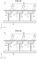
- a light detection device 1H illustrated in FIG. 16 the other end of a wall 30H is separated from the optical sensor 20.
- the wall 30H is provided so as to block the angle of view line VL, the effect similar to the effect of the wall 30 is obtained.
- one end of the wall 30H may be separated from the base portion 12.
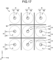
- FIG. 17 is a diagram illustrating an example of arrangement of through holes and walls in the pinhole array.
- FIG. 17 illustrates an example of a schematic configuration of a front view of the pinhole body 10G (plan view of the array).
- the plurality of through holes H are arranged at equal intervals in the X-axis direction and the Y-axis direction (the row direction and the column direction).
- the wall 30 partitions the through hole H into a quadrangular shape.
- FIG. 18 is a diagram illustrating another example of the arrangement of the through holes and the walls in the pinhole array.
- FIG. 18 illustrates another example of a schematic configuration of a front view of the pinhole body 10G (plan view of the array).
- the through holes H in adjacent columns (or rows) are arranged to be shifted from each other by an interval that is half the interval of the through holes H in each column.
- the wall 30 partitions the through hole H into a hexagonal shape.
- the wall 30 may partition the through hole H into any polygonal shape. This achieves high density arrangement of the plurality of through holes H.
- CMOS complementary metal oxide semiconductor
- CCD charge coupled device
- FIG. 19 is a diagram illustrating an example of a photodiode array used as an optical sensor.
- An optical sensor 20J included in a light detection device 1J illustrated in FIG. 19 includes a plurality of photodiodes PD provided in the form of an array.
- the photodiodes PD may be provided separated from each other.
- An example of the separation distance is 2 to 100 times the size of the photodiode PD.
- CMOS sensor or CCD sensor As the optical sensor will increase the unit price of the optical sensor.
- a light detection device using a pinhole body an image is formed in a wide range, but the brightness is greatly different between the center and the periphery of the image.
- imaging with this condition is performed by a single type of device, it is necessary to use a device having a very large dynamic range.
- the definition and the like of the obtained image are not so high and it is not necessary to reduce the pixel size of the optical sensor (image sensor) (where there is no need to use a high-definition sensor).
- the optical sensor 20J photodiode array
- the light detection device may be mounted on a transmissive display. This will be described with reference to FIG. 20 .
- FIG. 20 is a diagram illustrating an example of a schematic configuration of a display equipped with a light detection device.
- a light detection device 1K is provided in a transmissive display 40.
- An example of the transmissive display 40 is an organic light emitting diode (OLED) display.
- the transmissive display 40 includes a plurality of display pixel regions 41 and a corresponding plurality of wiring regions 42.
- the display pixel region 41 includes display pixels corresponding to individual colors of RGB, for example.
- the interval (pitch) of the adjacent display pixel regions 41 is 0.065 mm, for example.
- the display pixel region 41 is a portion that transmits light (light transmitting portion).
- the wiring region 42 includes a thin film transistor (TFT), a signal line, and the like used for purposes such as pixel driving of the corresponding display pixel region 41.
- the wiring region 42 is a portion that does not transmit light.
- the light detection device 1K is provided in the transmissive display 40 such that the through hole H is located in the display pixel region 41 (light transmitting portion).
- FIG. 20 illustrates the first hole H1 and the inner side surface 113 of the through hole H within the pinhole body 10.
- the second hole H2 and the optical sensor 20 described above are provided behind the first hole H1.
- the transmissive display 40 is provided with a light shielding member 43.
- the light shielding member 43 has substantially the same size (area) as the transmissive display 40.
- the light shielding member 43 shields a portion other than the through hole H in the transmissive display 40.
- the light shielding member 43 may be built, for example, when forming a TFT layer in the wiring region 42. With the present of the light shielding member 43, the transmissive display 40 has a structure that transmits light only through the first hole H1 and does not transmit light through other portions.
- the light detection device 1K it is possible to perform both display of an image and a video by the transmissive display 40 and detection (for example, imaging) of light from the front of the transmissive display 40.
- the light detection device can be used for various applications including an image sensor (imaging device or the like).
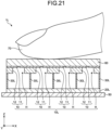
- the light detection device is applied as a fingerprint sensor (fingerprint detection device). This will be described with reference to FIG. 21 .
- FIG. 21 is a diagram illustrating an example of a schematic configuration of a light detection device applied as a fingerprint sensor.
- a light detection device 1L illustrated in FIG. 21 includes a pinhole body 10L, an optical sensor 20L, a wall 30L, a substrate 50, and a light guide plate 60 (for example, a glass plate).
- the pinhole body 10L includes a plurality of pinhole bodies 10 provided in the form of an array.
- the optical sensor 20L is a CMOS sensor, for example, and is provided on the light guide plate 60.
- the light guide plate 60 is provided in the pinhole body 10 L provided as a pinhole array.
- An example of the first application is fingerprint authentication.
- the fingerprint image is acquired in close-up by the light detection device including the pinhole array.
- Examples of applicable plate member through which a micropore (particularly indicating the first hole in a through hole) is drilled include various materials such as a metal having a thickness of 500 ⁇ m, a metal foil having a thickness of several nm, and an organic material such as leather.
- an aperture area having a diameter of about 30 ⁇ is optimal. This makes it possible to achieve both a size which is small enough but does not impair the sense of quality and a size large enough for achieving high luminance.
- a smartphone For a smartphone, a wearable device, and the like, it is suitable to use a configuration in which the light detection device is used for a display (refer to FIG. 20 ).
- Examples of wearable devices are smartwatches, head mounted displays (HMDs), and eyeglasses.
- a second application example is face authentication.
- a face image at a position away from several tens of centimeters to several meters is collected by the light detection device.
- the light detection device may be incorporated in a wall, an electrical appliance, or the like.
- Examples of applicable plate member through which a micropore is drilled include various materials such as a metal having a thickness of 500 ⁇ m, a metal foil having a thickness of several nm, and an organic material such as leather. Fabrication by printing is also possible. The optimum size of the micropore size varies depending on the authentication distance.
- an aperture area having a diameter of about 30 ⁇ m is optimal.
- an aperture area having a diameter of about 300 ⁇ m is optimal.
- a configuration of utilizing the light detection device in a display (refer to FIG. 20 ) is suitable.
- a third application example is object recognition in a refrigerator.
- the light detection device recognizes what is in the refrigerator.
- a refrigerator is often stuffed with many items, and blind spots are likely to occur, making it necessary to arrange a large number of sensors in order to prevent the blind spots.
- a micropore having a diameter of about 100 ⁇ m is drilled in a wall of a refrigerator, and an image is formed through the micropore.
- a large number of low-cost light detection devices of about 1 mm may be disposed on the entire walls, such as front, rear, left, right, and top and bottom walls inside the refrigerator.
- a fourth application example is a fall detection sensor.
- the light detection device monitors an abnormal state, such as a fall of a person falls due to illness or the like.
- an abnormal state such as a fall of a person falls due to illness or the like.
- a photodiode array (refer to FIG. 19 ) may be used as the imaging element instead of the CMOS.
- a fifth application example is automotive external sensing. Sensing at various wavelengths is needed. A high depth of field is also needed. A configuration including a plurality of micropores having different aperture areas (refer to FIG. 14 ) may be used. This is because a configuration capable of simultaneously utilizing a plurality of wavelengths and depth of field in the same sensor may be suitable.
- a sixth application example is a human sensor and a fire detection sensor. Sensing at various wavelengths is needed. On the other hand, low power consumption is needed.
- a photodiode array (refer to FIG. 19 ) may be used instead of a CMOS sensor or the like. By arranging PDs having different light receiving wavelengths, it is possible to have a configuration suitable for collecting information of various wavelengths at the same time.
- the light detection device 1 includes: the pinhole body 10 having the through hole H; and the optical sensor 20 that is provided behind the pinhole body 10 and receives light transmitted through the through hole H.
- the first aperture O1 of the through hole H arranged on the front surface 111 (first surface on the light incident surface side) of the pinhole body 10 is smaller than the second aperture O2 of the through hole H arranged on the back surface 122 (second surface opposite to the first surface).
- the through hole H may have the first hole H1 including the first aperture O1 and the second hole H2 including the second aperture 02, in which the depth of the second hole H2 from the back surface 122 may be greater than the depth of the first hole H1 from the front surface 111.
- the second hole H2 may have a size that does not interfere with image formation by the first hole H1.
- the first aperture O1 having a small aperture area functions as an aperture of the pinhole. Since the second aperture O2 has an aperture area larger than that of the first aperture O1, the second aperture O2 does not interfere with the pinhole function of the first aperture O1. In the presence of not only the portion corresponding to the first aperture O1 (surface portion 11) but also the portion corresponding to the second aperture O2 (base portion 12), the thickness of the pinhole body 10 is easily maintained (or easily increased).
- the angle of view V can be increased by thinning the portion (surface portion 11) corresponding to the first aperture O1.
- the aperture area of the second hole H2 may be constant with respect to the depth direction of the second hole H2. Since the second hole H2 has such a simple shape, the second hole H2 can be easily obtained.
- the aperture area of the second hole H2A to the second hole H2E may substantially increase toward the deeper portions in the depth direction of the second hole H2A to the second hole H2E.
- Examples of cross-sectional shapes of such second holes include a funnel shape ( FIG. 7 ), a staircase shape ( FIG. 8 ) and a wedge shape ( FIGS. 9 and 10 ). According to the second hole H2A to the second hole H2E with these shapes, the light reflected by the light receiving surface 20a of the optical sensor 20 is suppressed from being reflected again in the second hole H2A to the second hole H2E and returning to the light receiving surface 20a.
- the aperture of the second hole H2C2 and the aperture of the second hole H2C2 may have a polygonal shape. With these shapes, for example, in a case where a plurality of through holes is provided, it is possible to increase the area of images while suppressing overlapping of images formed by adjacent holes. This leads to acquisition of a larger amount of information.
- the pinhole body 10F may have the through holes HF1 to HF3 having aperture areas different from each other.
- the pinhole body 10G may be a pinhole array having the plurality of through holes H provided in the form of an array.
- the light detection device 1G may further include the wall 30 extending from a region between the plurality of through holes H toward a corresponding region of the optical sensor 20. This makes it possible to prevent incidence of unnecessary light, that is, overlapping of images formed by adjacent through holes H with each other. This makes it possible to acquire a large amount of information with a small light receiving area (for example, an imaging area).
- the wall 30 may be disposed so as to partition the through hole H into a polygonal shape. This makes it possible to arrange the plurality of through holes H at high density.
- the optical sensor 20J may be a photodiode array in which a plurality of photodiodes is arranged separated from each other. This can reduce the cost of the optical sensor.
- the light detection device 1K may be provided in the transmissive display 40 such that the through hole H is located in the light transmitting portion (display pixel region 41) of the transmissive display 40. This makes it possible to perform both display of an image and a video by the transmissive display 40 and detection (for example, imaging) of light from the front of the transmissive display 40.
- the pinhole body 10 may be a stacked body. This makes it possible to obtain the pinhole body 10 having a desired thickness using a plurality of plate members.
- the pinhole body 10 may have inner side surfaces (the inner side surface 113 and the inner side surface 123) forming the through hole H, and the inner side surface (the inner side surface 113 and/or the inner side surface 123) may have a light absorbing surface. With this configuration, light reflection in the through hole H is suppressed, making it possible to reduce the noise caused by reflected light.
- the pinhole body 10 may have the back surface 122 facing the optical sensor 20, and the back surface 122 may have a light absorbing surface. With this configuration, light reflection on the back surface 122 is suppressed, making it possible to reduce the noise caused by reflected light.
- the light detection device may be an imaging device or a fingerprint detection device as described with reference to FIG. 21 . This makes it possible to provide an imaging device or a fingerprint detection device capable of suppressing impairment of sense of quality.
- the technology according to the present disclosure (the present technology) is applicable to various products.
- the technology according to the present disclosure may be applied to devices mounted on any of moving objects such as automobiles, electric vehicles, hybrid electric vehicles, motorcycles, bicycles, personal mobility, airplanes, drones, ships, and robots.
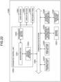
- FIG. 22 is a block diagram illustrating a schematic configuration example of a vehicle control system, which is an example of a moving object control system to which the technology according to the present disclosure is applicable.
- the vehicle control system 12000 includes a plurality of electronic control units connected to each other via a communication network 12001.
- the vehicle control system 12000 includes a driving system control unit 12010, a body system control unit 12020, an outside-vehicle information detecting unit 12030, an in-vehicle information detecting unit 12040, and an integrated control unit 12050.
- a microcomputer 12051, a sound/image output section 12052, and a vehicle-mounted network interface (I/F) 12053 are illustrated as a functional configuration of the integrated control unit 12050.
- the driving system control unit 12010 controls the operation of devices related to the driving system of the vehicle in accordance with various kinds of programs.
- the driving system control unit 12010 functions as a control device for a driving force generating device for generating the driving force of the vehicle, such as an internal combustion engine, a driving motor, or the like, a driving force transmitting mechanism for transmitting the driving force to wheels, a steering mechanism for adjusting the steering angle of the vehicle, a braking device for generating the braking force of the vehicle, and the like.
- the body system control unit 12020 controls the operation of various kinds of devices provided to a vehicle body in accordance with various kinds of programs.
- the body system control unit 12020 functions as a control device for a keyless entry system, a smart key system, a power window device, or various kinds of lamps such as a headlamp, a backup lamp, a brake lamp, a turn signal, a fog lamp, or the like.
- radio waves transmitted from a mobile device as an alternative to a key or signals of various kinds of switches can be input to the body system control unit 12020.
- the body system control unit 12020 receives these input radio waves or signals, and controls a door lock device, the power window device, the lamps, or the like of the vehicle.
- the outside-vehicle information detecting unit 12030 detects information about the outside of the vehicle including the vehicle control system 12000.
- the outside-vehicle information detecting unit 12030 is connected with an imaging section 12031.
- the outside-vehicle information detecting unit 12030 makes the imaging section 12031 image an image of the outside of the vehicle, and receives the imaged image.
- the outside-vehicle information detecting unit 12030 may perform processing of detecting an object such as a human, a vehicle, an obstacle, a sign, a character on a road surface, or the like, or processing of detecting a distance thereto.
- the imaging section 12031 is an optical sensor that receives light, and which outputs an electric signal corresponding to a received light amount of the light.
- the imaging section 12031 can output the electric signal as an image, or can output the electric signal as information about a measured distance.
- the light received by the imaging section 12031 may be visible light, or may be invisible light such as infrared rays or the like.
- the in-vehicle information detecting unit 12040 detects information about the inside of the vehicle.
- the in-vehicle information detecting unit 12040 is, for example, connected with a driver state detecting section 12041 that detects the state of a driver.
- the driver state detecting section 12041 for example, includes a camera that images the driver.
- the in-vehicle information detecting unit 12040 may calculate a degree of fatigue of the driver or a degree of concentration of the driver, or may determine whether the driver is dozing.
- the microcomputer 12051 can calculate a control target value for the driving force generating device, the steering mechanism, or the braking device on the basis of the information about the inside or outside of the vehicle which information is obtained by the outside-vehicle information detecting unit 12030 or the in-vehicle information detecting unit 12040, and output a control command to the driving system control unit 12010.
- the microcomputer 12051 can perform cooperative control intended to implement functions of an advanced driver assistance system (ADAS) which functions include collision avoidance or shock mitigation for the vehicle, following driving based on a following distance, vehicle speed maintaining driving, a warning of collision of the vehicle, a warning of deviation of the vehicle from a lane, or the like.
- ADAS advanced driver assistance system
- the microcomputer 12051 can perform cooperative control intended for automated driving, which makes the vehicle to travel automatedly without depending on the operation of the driver, or the like, by controlling the driving force generating device, the steering mechanism, the braking device, or the like on the basis of the information about the outside or inside of the vehicle which information is obtained by the outside-vehicle information detecting unit 12030 or the in-vehicle information detecting unit 12040.
- the microcomputer 12051 can output a control command to the body system control unit 12020 on the basis of the information about the outside of the vehicle which information is obtained by the outside-vehicle information detecting unit 12030.
- the microcomputer 12051 can perform cooperative control intended to prevent a glare by controlling the headlamp so as to change from a high beam to a low beam, for example, in accordance with the position of a preceding vehicle or an oncoming vehicle detected by the outside-vehicle information detecting unit 12030.
- the sound/image output section 12052 transmits an output signal of at least one of a sound and an image to an output device capable of visually or auditorily notifying information to an occupant of the vehicle or the outside of the vehicle.
- an audio speaker 12061, a display section 12062, and an instrument panel 12063 are illustrated as the output device.
- the display section 12062 may, for example, include at least one of an on-board display and a head-up display.
- FIG. 23 is a diagram illustrating an example of the installation position of the imaging section 12031.
- the imaging section 12031 includes imaging sections 12101, 12102, 12103, 12104, and 12105.
- the imaging sections 12101, 12102, 12103, 12104, and 12105 are, for example, disposed at positions on a front nose, sideview mirrors, a rear bumper, and a back door of the vehicle 12100 as well as a position on an upper portion of a windshield within the interior of the vehicle.
- the imaging section 12101 provided to the front nose and the imaging section 12105 provided to the upper portion of the windshield within the interior of the vehicle obtain mainly an image of the front of the vehicle 12100.
- the imaging sections 12102 and 12103 provided to the sideview mirrors obtain mainly an image of the sides of the vehicle 12100.
- the imaging section 12104 provided to the rear bumper or the back door obtains mainly an image of the rear of the vehicle 12100.
- the imaging section 12105 provided to the upper portion of the windshield within the interior of the vehicle is used mainly to detect a preceding vehicle, a pedestrian, an obstacle, a signal, a traffic sign, a lane, or the like.
- FIG. 23 illustrates an example of photographing ranges of the imaging sections 12101 to 12104.
- An imaging range 12111 represents the imaging range of the imaging section 12101 provided to the front nose.
- Imaging ranges 12112 and 12113 respectively represent the imaging ranges of the imaging sections 12102 and 12103 provided to the sideview mirrors.
- An imaging range 12114 represents the imaging range of the imaging section 12104 provided to the rear bumper or the back door.
- a bird's-eye image of the vehicle 12100 as viewed from above is obtained by superimposing image data imaged by the imaging sections 12101 to 12104, for example.
- At least one of the imaging sections 12101 to 12104 may have a function of obtaining distance information.
- at least one of the imaging sections 12101 to 12104 may be a stereo camera constituted of a plurality of imaging elements, or may be an imaging element having pixels for phase difference detection.
- the microcomputer 12051 can determine a distance to each three-dimensional object within the imaging ranges 12111 to 12114 and a temporal change in the distance (relative speed with respect to the vehicle 12100) on the basis of the distance information obtained from the imaging sections 12101 to 12104, and thereby extract, as a preceding vehicle, a nearest three-dimensional object in particular that is present on a traveling path of the vehicle 12100 and which travels in substantially the same direction as the vehicle 12100 at a predetermined speed (for example, equal to or more than 0 km/hour). Further, the microcomputer 12051 can set a following distance to be maintained in front of a preceding vehicle in advance, and perform automatic brake control (including following stop control), automatic acceleration control (including following start control), or the like. It is thus possible to perform cooperative control intended for automated driving that makes the vehicle travel automatedly without depending on the operation of the driver or the like.
- automatic brake control including following stop control
- automatic acceleration control including following start control
- the microcomputer 12051 can classify three-dimensional object data on three-dimensional objects into three-dimensional object data of a two-wheeled vehicle, a standard-sized vehicle, a large-sized vehicle, a pedestrian, a utility pole, and other three-dimensional objects on the basis of the distance information obtained from the imaging sections 12101 to 12104, extract the classified three-dimensional object data, and use the extracted three-dimensional object data for automatic avoidance of an obstacle.
- the microcomputer 12051 identifies obstacles around the vehicle 12100 as obstacles that the driver of the vehicle 12100 can recognize visually and obstacles that are difficult for the driver of the vehicle 12100 to recognize visually. Then, the microcomputer 12051 determines a collision risk indicating a risk of collision with each obstacle.
- the microcomputer 12051 In a situation in which the collision risk is equal to or higher than a set value and there is thus a possibility of collision, the microcomputer 12051 outputs a warning to the driver via the audio speaker 12061 or the display section 12062, and performs forced deceleration or avoidance steering via the driving system control unit 12010. The microcomputer 12051 can thereby assist in driving to avoid collision.
- At least one of the imaging sections 12101 to 12104 may be an infrared camera that detects infrared rays.
- the microcomputer 12051 can, for example, recognize a pedestrian by determining whether or not there is a pedestrian in imaged images of the imaging sections 12101 to 12104. Such recognition of a pedestrian is, for example, performed by a procedure of extracting characteristic points in the imaged images of the imaging sections 12101 to 12104 as infrared cameras and a procedure of determining whether or not it is the pedestrian by performing pattern matching processing on a series of characteristic points representing the contour of the object.
- the sound/image output section 12052 controls the display section 12062 so that a square contour line for emphasis is displayed so as to be superimposed on the recognized pedestrian.
- the sound/image output section 12052 may also control the display section 12062 so that an icon or the like representing the pedestrian is displayed at a desired position.
- the technology according to the present disclosure can be suitably applied to the imaging section 12031 among the configurations described above.
- the technology according to the present disclosure it is possible to suppress impairment of sense of quality.
- the technology according to the present disclosure (the present technology) is applicable to various products.
- the techniques according to the present disclosure may be applied to endoscopic surgery systems.
- FIG. 24 is a view illustrating an example of a schematic configuration of an endoscopic surgery system to which the technology according to an embodiment of the present disclosure (present technology) can be applied.
- FIG. 24 a state is illustrated in which a surgeon (medical doctor) 11131 is using an endoscopic surgery system 11000 to perform surgery for a patient 11132 on a patient bed 11133.
- the endoscopic surgery system 11000 includes an endoscope 11100, other surgical tools 11110 such as a pneumoperitoneum tube 11111 and an energy treatment tool 11112, a supporting arm apparatus 11120 which supports the endoscope 11100 thereon, and a cart 11200 on which various apparatus for endoscopic surgery are mounted.
- the endoscope 11100 includes a lens barrel 11101 having a region of a predetermined length from a distal end thereof to be inserted into a body lumen of the patient 11132, and a camera head 11102 connected to a proximal end of the lens barrel 11101.
- the endoscope 11100 is depicted which includes as a hard mirror having the lens barrel 11101 of the hard type.
- the endoscope 11100 may otherwise be included as a soft mirror having the lens barrel 11101 of the soft type.
- the lens barrel 11101 has, at a distal end thereof, an opening in which an objective lens is fitted.
- a light source apparatus 11203 is connected to the endoscope 11100 such that light generated by the light source apparatus 11203 is introduced to a distal end of the lens barrel 11101 by a light guide extending in the inside of the lens barrel 11101 and is irradiated toward an observation target in a body lumen of the patient 11132 through the objective lens.
- the endoscope 11100 may be a direct view mirror or may be a perspective view mirror or a side view mirror.
- An optical system and an image pickup element are provided in the inside of the camera head 11102 such that reflected light (observation light) from the observation target is condensed on the image pickup element by the optical system.
- the observation light is photo-electrically converted by the image pickup element to generate an electric signal corresponding to the observation light, namely, an image signal corresponding to an observation image.
- the image signal is transmitted as RAW data to a CCU 11201.
- the CCU 11201 includes a central processing unit (CPU), a graphics processing unit (GPU) or the like and integrally controls operation of the endoscope 11100 and a display apparatus 11202. Further, the CCU 11201 receives an image signal from the camera head 11102 and performs, for the image signal, various image processes for displaying an image based on the image signal such as, for example, a development process (demosaic process).
- a development process demosaic process
- the display apparatus 11202 displays thereon an image based on an image signal, for which the image processes have been performed by the CCU 11201, under the control of the CCU 11201.
- the light source apparatus 11203 includes a light source such as, for example, a light emitting diode (LED) and supplies irradiation light upon imaging of a surgical region to the endoscope 11100.
- a light source such as, for example, a light emitting diode (LED) and supplies irradiation light upon imaging of a surgical region to the endoscope 11100.
- LED light emitting diode
- An inputting apparatus 11204 is an input interface for the endoscopic surgery system 11000.
- a user can perform inputting of various kinds of information or instruction inputting to the endoscopic surgery system 11000 through the inputting apparatus 11204.
- the user would input an instruction or a like to change an image pickup condition (type of irradiation light, magnification, focal distance or the like) by the endoscope 11100.
- a treatment tool controlling apparatus 11205 controls driving of the energy treatment tool 11112 for cautery or incision of a tissue, sealing of a blood vessel or the like.
- a pneumoperitoneum apparatus 11206 feeds gas into a body lumen of the patient 11132 through the pneumoperitoneum tube 11111 to inflate the body lumen in order to secure the field of view of the endoscope 11100 and secure the working space for the surgeon.
- a recorder 11207 is an apparatus capable of recording various kinds of information relating to surgery.
- a printer 11208 is an apparatus capable of printing various kinds of information relating to surgery in various forms such as a text, an image or a graph.
- the light source apparatus 11203 which supplies irradiation light when a surgical region is to be imaged to the endoscope 11100 may include a white light source which includes, for example, an LED, a laser light source or a combination of them.
- a white light source includes a combination of red, green, and blue (RGB) laser light sources, since the output intensity and the output timing can be controlled with a high degree of accuracy for each color (each wavelength), adjustment of the white balance of a picked up image can be performed by the light source apparatus 11203.
- RGB red, green, and blue
- the light source apparatus 11203 may be controlled such that the intensity of light to be outputted is changed for each predetermined time.
- driving of the image pickup element of the camera head 11102 in synchronism with the timing of the change of the intensity of light to acquire images time-divisionally and synthesizing the images an image of a high dynamic range free from underexposed blocked up shadows and overexposed highlights can be created.
- the light source apparatus 11203 may be configured to supply light of a predetermined wavelength band ready for special light observation.
- special light observation for example, by utilizing the wavelength dependency of absorption of light in a body tissue to irradiate light of a narrow band in comparison with irradiation light upon ordinary observation (namely, white light), narrow band observation (narrow band imaging) of imaging a predetermined tissue such as a blood vessel of a superficial portion of the mucous membrane or the like in a high contrast is performed.
- fluorescent observation for obtaining an image from fluorescent light generated by irradiation of excitation light may be performed.
- fluorescent observation it is possible to perform observation of fluorescent light from a body tissue by irradiating excitation light on the body tissue (autofluorescence observation) or to obtain a fluorescent light image by locally injecting a reagent such as indocyanine green (ICG) into a body tissue and irradiating excitation light corresponding to a fluorescent light wavelength of the reagent upon the body tissue.
- a reagent such as indocyanine green (ICG)
- ICG indocyanine green
- the light source apparatus 11203 can be configured to supply such narrowband light and/or excitation light suitable for special light observation as described above.
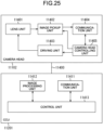
- FIG. 25 is a block diagram illustrating an example of a functional configuration of the camera head 11102 and the CCU 11201 illustrated in FIG. 24 .
- the camera head 11102 includes a lens unit 11401, an image pickup unit 11402, a driving unit 11403, a communication unit 11404 and a camera head controlling unit 11405.
- the CCU 11201 includes a communication unit 11411, an image processing unit 11412 and a control unit 11413.
- the camera head 11102 and the CCU 11201 are connected for communication to each other by a transmission cable 11400.
- the lens unit 11401 is an optical system, provided at a connecting location to the lens barrel 11101. Observation light taken in from a distal end of the lens barrel 11101 is guided to the camera head 11102 and introduced into the lens unit 11401.
- the lens unit 11401 includes a combination of a plurality of lenses including a zoom lens and a focusing lens.
- the number of image pickup elements which is included by the image pickup unit 11402 may be one (single-plate type) or a plural number (multi-plate type). Where the image pickup unit 11402 is configured as that of the multi-plate type, for example, image signals corresponding to respective R, G and B are generated by the image pickup elements, and the image signals may be synthesized to obtain a color image.
- the image pickup unit 11402 may also be configured so as to have a pair of image pickup elements for acquiring respective image signals for the right eye and the left eye ready for three dimensional (3D) display. If 3D display is performed, then the depth of a living body tissue in a surgical region can be comprehended more accurately by the surgeon 11131. It is to be noted that, where the image pickup unit 11402 is configured as that of stereoscopic type, a plurality of systems of lens units 11401 are provided corresponding to the individual image pickup elements.
- the image pickup unit 11402 may not necessarily be provided on the camera head 11102.
- the image pickup unit 11402 may be provided immediately behind the objective lens in the inside of the lens barrel 11101.
- the driving unit 11403 includes an actuator and moves the zoom lens and the focusing lens of the lens unit 11401 by a predetermined distance along an optical axis under the control of the camera head controlling unit 11405. Consequently, the magnification and the focal point of a picked up image by the image pickup unit 11402 can be adjusted suitably.
- the communication unit 11404 includes a communication apparatus for transmitting and receiving various kinds of information to and from the CCU 11201.
- the communication unit 11404 transmits an image signal acquired from the image pickup unit 11402 as RAW data to the CCU 11201 through the transmission cable 11400.
- the communication unit 11404 receives a control signal for controlling driving of the camera head 11102 from the CCU 11201 and supplies the control signal to the camera head controlling unit 11405.
- the control signal includes information relating to image pickup conditions such as, for example, information that a frame rate of a picked up image is designated, information that an exposure value upon image picking up is designated and/or information that a magnification and a focal point of a picked up image are designated.
- the image pickup conditions such as the frame rate, exposure value, magnification or focal point may be designated by the user or may be set automatically by the control unit 11413 of the CCU 11201 on the basis of an acquired image signal.
- an auto exposure (AE) function, an auto focus (AF) function and an auto white balance (AWB) function are incorporated in the endoscope 11100.
- the camera head controlling unit 11405 controls driving of the camera head 11102 on the basis of a control signal from the CCU 11201 received through the communication unit 11404.
- the communication unit 11411 includes a communication apparatus for transmitting and receiving various kinds of information to and from the camera head 11102.
- the communication unit 11411 receives an image signal transmitted thereto from the camera head 11102 through the transmission cable 11400.
- the communication unit 11411 transmits a control signal for controlling driving of the camera head 11102 to the camera head 11102.
- the image signal and the control signal can be transmitted by electrical communication, optical communication or the like.
- the image processing unit 11412 performs various image processes for an image signal in the form of RAW data transmitted thereto from the camera head 11102.
- the control unit 11413 performs various kinds of control relating to image picking up of a surgical region or the like by the endoscope 11100 and display of a picked up image obtained by image picking up of the surgical region or the like. For example, the control unit 11413 creates a control signal for controlling driving of the camera head 11102.
- control unit 11413 controls, on the basis of an image signal for which image processes have been performed by the image processing unit 11412, the display apparatus 11202 to display a picked up image in which the surgical region or the like is imaged.
- control unit 11413 may recognize various objects in the picked up image using various image recognition technologies.
- the control unit 11413 can recognize a surgical tool such as forceps, a particular living body region, bleeding, mist when the energy treatment tool 11112 is used and so forth by detecting the shape, color and so forth of edges of objects included in a picked up image.
- the control unit 11413 may cause, when it controls the display apparatus 11202 to display a picked up image, various kinds of surgery supporting information to be displayed in an overlapping manner with an image of the surgical region using a result of the recognition. Where surgery supporting information is displayed in an overlapping manner and presented to the surgeon 11131, the burden on the surgeon 11131 can be reduced and the surgeon 11131 can proceed with the surgery with certainty.
- the transmission cable 11400 which connects the camera head 11102 and the CCU 11201 to each other is an electric signal cable ready for communication of an electric signal, an optical fiber ready for optical communication or a composite cable ready for both of electrical and optical communications.
- communication is performed by wired communication using the transmission cable 11400
- the communication between the camera head 11102 and the CCU 11201 may be performed by wireless communication.
- the technique according to the present disclosure may be applied to, for example, a microscopic surgery system or the like.
Landscapes
- Engineering & Computer Science (AREA)
- Physics & Mathematics (AREA)
- General Physics & Mathematics (AREA)
- Human Computer Interaction (AREA)
- Multimedia (AREA)
- Theoretical Computer Science (AREA)
- Chemical & Material Sciences (AREA)
- Inorganic Chemistry (AREA)
- Spectroscopy & Molecular Physics (AREA)
- Sustainable Development (AREA)
- Life Sciences & Earth Sciences (AREA)
- Health & Medical Sciences (AREA)
- General Health & Medical Sciences (AREA)
- Oral & Maxillofacial Surgery (AREA)
- Optical Elements Other Than Lenses (AREA)
- Image Input (AREA)
- Photometry And Measurement Of Optical Pulse Characteristics (AREA)
- Solid State Image Pick-Up Elements (AREA)
- Transforming Light Signals Into Electric Signals (AREA)
- Studio Devices (AREA)
- Light Receiving Elements (AREA)
Abstract
Description
- The present disclosure relates to a light detection device. Background
- An imaging device that performs imaging using a pinhole is known (refer to
Patent Literature 1, for example). - Patent Literature 1:
JP 2016-25164 A - In order to obtain a high angle of view with the pinhole, it is conceivable to reduce the depth of the pinhole This, however, would thin a portion constituting the pinhole, leading to impairment of sense of quality.
- The present disclosure, in one aspect, aims to provide a light detection device capable of suppressing impairment of sense of quality in a portion constituting a pinhole.
- A light detection device according to one aspect of the present disclosure includes: a pinhole body provided with a through hole; and an optical sensor that is provided behind the pinhole body and receives light transmitted through the through hole, wherein a first aperture of the through hole is smaller than a second aperture of the through hole, the first aperture being provided in a first surface of the pinhole body, the first surface being a surface on an incident surface side of the light, the second aperture being provided in a second surface of the pinhole body, the second surface being a surface opposite to the first surface.
-
-
FIG. 1 is a conceptual view illustrating light detection using a pinhole. -
FIG. 2 is a conceptual view illustrating light detection using a pinhole. -
FIG. 3 is a diagram illustrating an example of a schematic configuration of a light detection device according to an embodiment. -
FIG. 4 is a front view illustrating an example of an appearance of a pinhole body. -
FIG. 5 is a front view illustrating an example of an appearance of a pinhole body. -
FIG. 6 is a view illustrating an example of a cross-sectional shape of a pinhole body. -
FIG. 7 is a view illustrating an example of a cross-sectional shape of a pinhole body. -
FIG. 8 is a view illustrating an example of a cross-sectional shape of a pinhole body. -
FIG. 9 is a view illustrating an example of a cross-sectional shape of a pinhole body. -
FIG. 10 is a view illustrating an example of a cross-sectional shape of a pinhole body. -
FIG. 11 is a view illustrating an example of an aperture shape of a pinhole body. -
FIG. 12 is a view illustrating an example of an aperture shape of a pinhole body. -
FIG. 13 is a view illustrating an example of an aperture shape of a pinhole body. -
FIG. 14 is a view illustrating an arrangement example of a plurality of through holes having different aperture areas. -
FIG. 15 is a diagram illustrating an example of a schematic configuration of a light detection device including a pinhole array. -
FIG. 16 is a diagram illustrating an example of a schematic configuration of a light detection device including a pinhole array. -
FIG. 17 is a diagram illustrating an example of arrangement of through holes and walls in a pinhole array. -
FIG. 18 is a diagram illustrating an example of arrangement of through holes and walls in a pinhole array. -
FIG. 19 is a view illustrating an example of a photodiode array used as an optical sensor. -
FIG. 20 is a diagram illustrating an example of a schematic configuration of a display equipped with a light detection device. -
FIG. 21 is a diagram illustrating an example of a schematic configuration of a light detection device applied as a fingerprint sensor. -
FIG. 22 is a block diagram illustrating an example of schematic configuration of a vehicle control system. -
FIG. 23 is a diagram illustrating an example of installation positions of an outside-vehicle information detector and an imaging section. -
FIG. 24 is a diagram illustrating an example of a schematic configuration of an endoscopic surgery system. -
FIG. 25 is a block diagram illustrating an example of a functional configuration of a camera head and a CCU. - Embodiments of the present disclosure will be described below in detail with reference to the drawings. In each of the following embodiments, the same parts are denoted by the same reference numerals, and a repetitive description thereof will be omitted.
- The present disclosure will be described in the following order.
- 1. Introduction
- 2. Embodiments
- 2.1 Example of cross-sectional shape of pinhole body
- 2.2 Arrangement example of plurality of through holes having different aperture areas.
- 2.3 Example of pinhole array
- 2.4 Example of photodiode sensor
- 2.5 Example of mounting on display
- 2.6 Example of fingerprint sensor
- 3. Application Examples
- 4. Effects
- 5. Example of application to moving object
- 6. Example of application to endoscopic surgery system
-
FIGS. 1 and 2 are diagrams conceptually illustrating light detection by pinholes.FIGS. 1 and 2 illustrate two types of pinholes PH1 and PH2 having different aperture areas. Solid arrows extending downward from the top in the drawing conceptually indicate beams of light traveling toward the pinhole PH1 and the pinhole PH2. - In the example illustrated in
FIGS. 1 and 2 , the pinhole PH1 and the pinhole PH2 have the same depth and mutually different aperture areas. The aperture area of the pinhole PH2 is smaller than the aperture area of the pinhole PH1. Accordingly, an angle of view V2 corresponding to the pinhole PH2 is smaller than an angle of view V1 corresponding to the pinhole PH1. An image forming range R2 of the pinhole PH2 is smaller (narrower) than an image forming range R1 of the pinhole PH1. In this manner, by using a pinhole having a small aperture area, it is possible to improve definition, modulation transfer function (MTF), and the like (hereinafter, simply referred to as "definition, etc."). When the aperture areas of the pinholes are the same, definition, etc. is improved by using a pinhole having a large depth. - For example, in order to increase the angle of view while maintaining the definition and the like, it is necessary to reduce the depth of the pinhole. In order to thin the portion where the pinhole is formed, there would be a need to use a very thin film-like material, and this would impair a sense of quality. It is desirable to maintain the angle of view and/or the definition, etc. while suppressing the impairment of sense of quality.
-
FIG. 3 is a diagram illustrating an example of a schematic configuration of a light detection device according to an embodiment. In the figure, an XYZ coordinate system is illustrated. The Z-axis direction corresponds to the depth (front-rear) direction of the light detection device. The X-axis direction and the Y-axis direction respectively correspond to horizontal (right-left) and vertical (up-down) directions of the light detection device. A detection target of the light detection device is assumed to exist in front of the light detection device (on the Z-axis positive direction side). -
FIG. 3 is a cross-sectional view of thelight detection device 1 when viewed from a direction (in this example, the Y-axis direction) intersecting the Z-axis direction. Thelight detection device 1 includes: apinhole body 10; and anoptical sensor 20 provided behind (on the Z-axis negative direction side of) thepinhole body 10. - The
pinhole body 10 is provided with a through hole H. The through hole H is a hole (pinhole) penetrating thepinhole body 10 in the Z-axis direction. For convenience of description, the through hole H is illustrated as two holes, namely, a first hole H1 and a second hole H2. A portion of thepinhole body 10 corresponding to the first hole H1 is referred to as asurface portion 11 in the drawing. A portion of thepinhole body 10 corresponding to the second hole H2 is referred to as abase portion 12 in the drawing. Thesurface portion 11 and thebase portion 12 may be formed as separately molded portions or an integrally molded portion. - The
surface portion 11 has afront surface 111, aback surface 112, aninner side surface 113, and anouter side surface 114. - The
front surface 111 and theback surface 112 extend in an XY plane direction and face each other in the Z-axis direction. Thefront surface 111 constitutes a first surface which is a light incident surface side of thepinhole body 10. A first aperture O1 of the through hole H disposed in thefront surface 111 is smaller than a second aperture O2 of the through hole H disposed in a second surface (aback surface 122 to be described below) opposite to thefront surface 111. Theback surface 112 is a surface opposite to thefront surface 111 in thesurface portion 11. - The
inner side surface 113 and theouter side surface 114 extend in the Z-axis direction and face each other in the X-axis direction (or the Y-axis direction). Theinner side surface 113 forms the first hole H1 of the through hole H. When viewed in the direction intersecting the Z-axis direction (in this example, the Y-axis direction), a separation distance between the inner side surfaces 113 facing each other across the first hole H1 is constant in a depth direction. The first hole H1 has a cross-sectional shape having a constant aperture area in the depth direction. Theinner side surface 113 may have a light absorbing surface. With this configuration, light reflection in the first hole H1 is suppressed, leading to reduction of noise (stray light or the like) caused by reflected light. The light absorbing surface may be formed by performing application, plating, etching, or the like, of a light absorbing material (for example, black paint) to a portion corresponding to theinner side surface 113 of thesurface portion 11. Light absorption processing may be performed instead of applying the light absorbing material or the like. Theouter side surface 114 is a surface opposite to theinner side surface 113 in thesurface portion 11, and constitutes a part of the outer side surface of thepinhole body 10. - The
base portion 12 has aback surface 122, aninner side surface 123, and anouter side surface 124. In a case where thebase portion 12 is formed separately from thesurface portion 11, the base portion also has afront surface 121. Hereinafter, this case will be described. - The
front surface 121 and theback surface 122 extend in the XY plane direction and face each other in the Z-axis direction. Thefront surface 121 is a front-side surface of thebase portion 12 and faces theback surface 112 of thesurface portion 11. Theback surface 122 is a surface of thebase portion 12 opposite to thefront surface 121. Theback surface 122 constitutes a second surface opposite to a front surface 111 (first surface) of thepinhole body 10. Theback surface 122 faces theoptical sensor 20. Theback surface 122 may have a light absorbing surface. With this configuration, light reflection on theback surface 122 is suppressed, leading to reduction of noise caused by reflected light. The light absorbing surface may be similar to the light absorbing surface of theinner side surface 113 described above. The second aperture O2 of the through hole H provided on theback surface 122 is larger than the first aperture O1 of the through hole H provided on thefront surface 111. - The
inner side surface 123 and theouter side surface 124 extend in the Z-axis direction and face each other in the X-axis direction (or the Y-axis direction). Theinner side surface 123 forms the second hole H2 of the through hole H. The depth of the second hole H2 from theback surface 122 is greater than the depth of the first hole H1 from thefront surface 111. When viewed in the direction intersecting the Z-axis direction (in this example, the Y-axis direction), the separation distance between the inner side surfaces 123 facing each other across the second hole H2 is constant in the depth direction. The second hole H2 has an aperture area larger than the aperture area of the first hole H1 at the boundary between the first hole H1 and the second hole H2, and has a cross-sectional shape (cylindrical shape) in which the aperture area is constant in the depth direction of the second hole H2. Theinner side surface 123 may have a light absorbing surface. With this configuration, light reflection in the second hole H2 is suppressed, leading to reduction of noise caused by reflected light. The light absorbing surface may be similar to theinner side surface 113 described above. - An angle of view corresponding to the first hole H1 is referred to as an angle of view V in the drawing. In
FIG. 3 , a line indicating the angle of view V is referred to as an angle of view line VL. The angle of view line VL is a virtual straight line passing through the front end of the oneinner side surface 113 and the rear end of the otherinner side surface 113 facing each other with the first hole H1 interposed therebetween. The second hole H2 may have a size that does not interfere with image formation by the first hole H1. In this case, theinner side surface 123 forming the second hole H2 is positioned outside the angle of view line VL. That is, the angle of view V corresponding to the first hole H1 is not to be narrowed by the second hole H2. - The
optical sensor 20 receives light passing through the through hole H. Theoptical sensor 20 is provided behind thepinhole body 10. Theoptical sensor 20 has alight receiving surface 20a. Thelight receiving surface 20a extends in the XY plane direction and faces theback surface 112 and theback surface 122 of thepinhole body 10 in the Z-axis direction. Thelight receiving surface 20a is formed to receive light within the angle of view V. The area of thelight receiving surface 20a may be larger than the aperture area of the second hole H2. With this dimension, even when theoptical sensor 20 is provided separated from thepinhole body 10 in particular, the light within the angle of view V can be received by thelight receiving surface 20a. -
FIG. 4 is a front view illustrating an example of an appearance of a schematic configuration of the pinhole body. In this example, the aperture of the first hole H1 has a circular shape. When viewed from the front, thefront surface 111 of thesurface portion 11 of thepinhole body 10 occupies most of thepinhole body 10. This portion is a portion that is often observed or touched by the user of the light detection device 1 (that is, regarded as an indicator of the sense of quality of thepinhole body 10 by the user). Therefore, thefront surface 111 of thesurface portion 11 has a large effect on the sense of quality of thepinhole body 10. This sense of quality comes from the material, the thickness (the length in the Z-axis direction), and the like of thesurface portion 11 and thebase portion 12 provided on the back side of the surface portion 11 (that is, the entire pinhole body 10). Examples of the material are metals such as stainless steel and aluminum. However, the material is not limited thereto, and various materials may be used. The greater the thickness ofpinhole body 10, the higher the sense of quality is likely to be obtained. The smaller the thickness of thepinhole body 10, the more likely the sense of quality is to be impaired. -
FIG. 5 is a rear view illustrating an example of an appearance of a schematic configuration of the pinhole body. In this example, the aperture of the second hole H2 has a circular shape. When viewed from the rear, theback surface 112 of thesurface portion 11 of thepinhole body 10 and theback surface 122 of thebase portion 12 occupy most of thepinhole body 10. - In the
light detection device 1 described above, the first aperture O1 having a small aperture area, among the first aperture O1 and the second aperture O2 (the first hole H1 and the second hole H2), functions as an aperture of the pinhole. Since the second aperture O2 has an aperture area larger than that of the first aperture O1, the second aperture O2 does not interfere with the pinhole function of the first aperture O1. In the presence of not only the portion corresponding to the first aperture O1 (surface portion 11) but also the portion corresponding to the second aperture O2 (base portion 12), the thickness of thepinhole body 10 is easily maintained (or easily increased). The angle of view V can be increased by thinning the portion (surface portion 11) corresponding to the first aperture O1. Even in this case, since the thickness ofpinhole body 10 is maintained, the sense of quality would not be impaired. This configuration also maintains the strength. For example, if there is a partially thin portion in thepinhole body 10, the sense of quality might be deteriorated at the time of processing such as hairline processing. However, this configuration can also suppress such deterioration in the sense of quality. - The
pinhole body 10 capable of having the sense of quality has a thickness of 300 µm or more, for example. Such apinhole body 10 can be manufactured as follows, for example. First, six plate members each having a thickness of 50 µm are prepared. One of the plate members is processed to have the first hole H1 (for example, a diameter of 50 µm or the like) so as to be used as thesurface portion 11. The remaining five plate members are processed to have the second hole H2 (for example, a diameter of 250 µm or a diameter of 700 µm) so as to be used as thebase portion 12. These plate members are bonded to each other by diffusion bonding or the like, so as to obtain thepinhole body 10. Such apinhole body 10 may be a stacked body having a structure with stacked layers. In the above-described example, thesurface portion 11 has a single layer structure (corresponding to one plate member), while thebase portion 12 has a multilayer structure (corresponding to five plate members). - The second hole of the pinhole body may have various cross-sectional shapes other than the cross-sectional shape illustrated in
FIG. 3 described above. Some examples of the cross-sectional shape of the pinhole body will be described with reference toFIGS. 6 to 10 . - A through hole HA of a
pinhole body 10A illustrated inFIG. 6 has a second hole H2A. The second hole H2A has a tapered cross-sectional shape in which the aperture area increases at a constant rate toward deeper portions in the depth direction. Thebase portion 12A of thepinhole body 10 has aninner side surface 123A forming the second hole H2A. The separation distance between theinner side surfaces 123A facing each other across the second hole H2A increases toward deeper portions in the depth direction of the second hole H2A. The second hole H2A has the same aperture area as the aperture area of the first hole H1 at the boundary between the first hole H1 and the second hole H2A, and has a cross-sectional shape (tapered shape) in which the aperture area increases at a constant rate toward deeper portions in the depth direction of the second hole H2A. - A through hole HB of a
pinhole body 10B illustrated inFIG. 7 has a second hole H2B. The second hole H2B has a cross-sectional shape in which the aperture area increases at a different rate toward deeper portions in the depth direction. Thebase portion 12B of thepinhole body 10B has aninner side surface 123B forming the second hole H2B. The separation distance between the inner side surfaces 123B facing each other across the second hole H2B increases toward deeper portions in the depth direction of the second hole H2B. The second hole H2B has the same aperture area as the aperture area of the first hole H1 at the boundary between the first hole H1 and the second hole H2B, and has a cross-sectional shape (funnel shape curved to bulge downward) that increases from the boundary toward deeper portions in the depth direction of the second hole H2B (at a gradually decreasing change rate). The cross-sectional shape of the second hole H2B may be a funnel shape curved so as to bulge upward. - A through hole HC of a
pinhole body 10C illustrated inFIG. 8 has a second hole H2C. The second hole H2C has a cross-sectional shape in which the aperture area increases stepwise toward deeper portions in the depth direction. Abase portion 12C of thepinhole body 10C has aninner side surface 123C forming the second hole H2C. The separation distance between the inner side surfaces 123C facing each other across the second hole H2C increases stepwise toward deeper portions in the depth direction of the second hole H2C. The second hole H2C has an aperture area that is one step larger than the aperture area of the first hole H1 at the boundary between the first hole H1 and the second hole H2C, and has a cross-sectional shape (staircase shape) that further increases stepwise toward deeper portions in the depth direction of the second hole H2C. - A through hole HD of a
pinhole body 10D illustrated inFIG. 9 has a second hole H2D. The second hole H2D has a cross-sectional shape in which the aperture area increases stepwise toward deeper portions in the depth direction. Abase portion 12D of thepinhole body 10D has aninner side surface 123D forming the second hole H2D. The separation distance between theinner side surfaces 123D facing each other across the second hole H2D increases stepwise while alternating reduction and expansion toward deeper portions in the depth direction of the second hole H2D. The second hole H2D has an aperture area that is one step larger than the aperture area of the first hole H1 at the boundary between the first hole H1 and the second hole H2D, and has a shape (wedge shape) that further increases stepwise while alternating reduction and expansion toward deeper portions in the depth direction of the second hole H2D. - A through hole HE of a
pinhole body 10E illustrated inFIG. 10 has a second hole H2E. The second hole H2E has a cross-sectional shape in which the aperture area increases stepwise toward deeper portions in the depth direction. Aninner side surface 123E of abase portion 12E of apinhole body 10E is further recessed in a direction away from the optical sensor 20 (Z-axis positive direction) as compared with theinner surface 123D (FIG. 9 ). A part of aback surface 112E of asurface portion 11E of thepinhole body 10E is recessed in a direction away from the optical sensor 20 (Z-axis positive direction) so as to form a part of the second hole H2E. The second hole H2E has an aperture area that is one step larger than the aperture area of the first hole H1 at the boundary between the first hole H1 and the second hole H2E, and has a shape (inclined wedge shape) that further increases stepwise toward deeper portions in the depth direction of the second hole H2E. - As described with reference to
FIGS. 6 to 10 , with a configuration in which the aperture area of the second hole substantially increases (including increasing stepwise in addition to increasing monotonically) toward deeper portions in the depth direction, it is possible to suppress a phenomenon that the light reflected by thelight receiving surface 20a of theoptical sensor 20 will be reflected again in the second hole and return to thelight receiving surface 20a. The second holes H2A to H2E are obtained, for example, by preparing a plate-like (thin film-like) material to be a base material of thebase portions 12A to 12E and processing the material into a desired shape by machining. Examples of the machining method include cutting and laser machining. The shapes of the first hole H1A to the first hole H1E and the second hole H2A to the second hole H2E may be manufactured by the imprint fabrication. At this time, a plurality of molds may be used. The surface portion 11A to thesurface portion 11E and thebase portion 12A to thebase portion 12E may be grown by performing plating or the like on the shape formed by the imprint fabrication. - Some examples of the aperture shape of the second hole of the pinhole body will be described with reference to
FIGS. 11 to 13 . Here, a case where the second hole has a staircase shape (corresponding to thepinhole body 10C inFIG. 8 ) will be described as an example.FIGS. 11 to 13 are rear views illustrating an example of an appearance of a schematic configuration of the pinhole body. - In the through hole HC1 illustrated in
FIG. 11 , the aperture of a second hole H2C1 has a circular shape similarly to the aperture of the first hole H1C. In the figure, a surface forming the second hole H2C1 is illustrated as an inner side surface 123C1. - In a through hole HC2 illustrated in
FIG. 12 , the aperture of a second hole H2C2 has a rectangular shape (in this example, a square shape). In the figure, a surface forming the second hole H2C2 is illustrated as an inner side surface 123C2. - In a through hole HC3 illustrated in
FIG. 13 , the aperture of a second hole H2C3 has a polygonal shape (hexagonal shape in this example). In the figure, a surface forming the second hole H2C3 is illustrated as an inner side surface 123C3. - Since the aperture of the second hole has a rectangular shape, a polygonal shape, or the like as illustrated in
FIGS. 12 and 13 , it is possible, with a plurality of through holes, to increase (for example, maximize) the area of the image while suppressing overlapping of images formed by adjacent through holes, as compared with the case of the circular shape. This leads to acquisition of a larger amount of information. - In one embodiment, the pinhole body has a plurality of through holes having aperture areas different from each other. This will be described with reference to
FIG. 14 . -
FIG. 14 is a diagram illustrating an example of arrangement of a plurality of through holes having different aperture areas. Apinhole body 10F illustrated inFIG. 14 has three types of through holes: a through hole HF1 to a through hole HF3.FIG. 14 is a front view of thepinhole body 10F. An optical sensor (not illustrated) that receives light passing through the through holes HF1 to HF3 is provided behind the through holes HF1 to HF3. - The through holes HF1 to HF3 have aperture areas different from each other, and are provided at different positions. In this example, the aperture area (for example, 40 µm) of a first hole H1F2 of the through hole HF2 is smaller than the aperture area (for example, 50 µm) of a first hole H1F1 of the through hole HF1. An aperture area (for example, 60 µm) of a first hole H1F3 of the through hole HF3 is larger than an aperture area of the first hole H1F1 of the through hole HF1. A second hole H2F1 of the through hole HF1, a second hole H2F2 of the through hole HF2, and a second hole H2F3 of the through hole HF3 may have a similar relationship. There may be a plurality of through holes having the same aperture area, and in this example, there are two through holes HF1.
- In the light detection device including the
pinhole body 10F, the light passing through each of the plurality of through holes can be detected by the optical sensor. In this case, by using the detection results of the plurality of beams of light, it is possible to obtain an optimum detection result (for example, an image or the like) as compared with the case of using only the detection result of one beam of light. For example, since the depth of field varies depending on the distance to the subject, the wavelength of light, and the like, it is possible to use the detection result of the light passing through the through hole giving the optimum depth of field among the plurality of through holes. By using the detection result of the light passing through the through hole other than the through hole giving the optimum depth of field, it is also possible to improve the detection accuracy (for example, image recognition accuracy or the like). - In one embodiment, the pinhole body is provided as a pinhole array having a plurality of through holes provided in the form of an array. This will be described with reference to
FIGS. 15 to 18 . -
FIG. 15 is a diagram illustrating an example of a schematic configuration of a light detection device including a pinhole array. As compared with the pinhole body 10 (FIG. 3 ), alight detection device 1G illustrated inFIG. 15 has a difference in that it includes apinhole body 10G instead of thepinhole body 10 and further includes awall 30. - The
pinhole body 10G has a plurality of through holes H provided in the form of an array. In this example, thepinhole body 10G is formed as a plurality ofpinhole bodies 10 provided in the form of an array. - The
wall 30 extends from a region between the plurality of through holes H toward a corresponding region of theoptical sensor 20. In this example, thewall 30 extends from theback surface 122 of thebase portion 12 towards theoptical sensor 20. One end of thewall 30 is in contact with theback surface 122 of thebase portion 12. The other end of thewall 30 is in contact with theoptical sensor 20. Thewall 30 is provided so as to block the angle of view line VL (so as to intersect the angle of view line VL). Thewall 30 may be made of the same material as or a different material frombase portion 12 of thepinhole body 10. The surface of thewall 30 may have a light absorbing surface. With this configuration, light reflection on thewall 30 is suppressed, leading to reduction of noise caused by reflected light. The light absorbing surface may be similar to the light absorbing surface of theinner side surface 113 described above. - In the case of the
light detection device 1G without thewall 30, unnecessary light from another through hole H (for example, an adjacent through hole H) is incident on theoptical sensor 20. By comparison, in the case of thelight detection device 1 including thewall 30, even when thepinhole bodies 10 are not arranged apart from each other, it is still possible to prevent incidence of unnecessary light, that is, prevent overlapping of images formed by the adjacent through holes H. This makes it possible to acquire a large amount of information with a small light receiving area (for example, an imaging area). - The above is example in which the
wall 30 is in contact with theoptical sensor 20. Alternatively, the wall may be separated from the optical sensor. In alight detection device 1H illustrated inFIG. 16 , the other end of awall 30H is separated from theoptical sensor 20. Also in this case, since thewall 30H is provided so as to block the angle of view line VL, the effect similar to the effect of thewall 30 is obtained. Note that, instead of the other end of thewall 30H, one end of thewall 30H may be separated from thebase portion 12. -
FIG. 17 is a diagram illustrating an example of arrangement of through holes and walls in the pinhole array.FIG. 17 illustrates an example of a schematic configuration of a front view of thepinhole body 10G (plan view of the array). In this example, the plurality of through holes H are arranged at equal intervals in the X-axis direction and the Y-axis direction (the row direction and the column direction). Thewall 30 partitions the through hole H into a quadrangular shape. -
FIG. 18 is a diagram illustrating another example of the arrangement of the through holes and the walls in the pinhole array.FIG. 18 illustrates another example of a schematic configuration of a front view of thepinhole body 10G (plan view of the array). In this example, the through holes H in adjacent columns (or rows) are arranged to be shifted from each other by an interval that is half the interval of the through holes H in each column. Thewall 30 partitions the through hole H into a hexagonal shape. - Not limited to the example illustrated in
FIGS. 17 and18 , thewall 30 may partition the through hole H into any polygonal shape. This achieves high density arrangement of the plurality of through holes H. - Typical examples of the optical sensor used in the light detection device include a complementary metal oxide semiconductor (CMOS) sensor and a charge coupled device (CCD) sensor. Alternatively, it is also allowable to use a sensor other than these sensors, for example, a photodiode array. This will be described with reference to
FIG. 19 . -
FIG. 19 is a diagram illustrating an example of a photodiode array used as an optical sensor. Anoptical sensor 20J included in alight detection device 1J illustrated inFIG. 19 includes a plurality of photodiodes PD provided in the form of an array. The photodiodes PD may be provided separated from each other. An example of the separation distance is 2 to 100 times the size of the photodiode PD. - Using a device such as a CMOS sensor or a CCD sensor as the optical sensor will increase the unit price of the optical sensor. In addition, when using a light detection device using a pinhole body, an image is formed in a wide range, but the brightness is greatly different between the center and the periphery of the image. When imaging with this condition is performed by a single type of device, it is necessary to use a device having a very large dynamic range. Meanwhile, there is another case where the definition and the like of the obtained image are not so high and it is not necessary to reduce the pixel size of the optical sensor (image sensor) (where there is no need to use a high-definition sensor). In this case, by using the
optical sensor 20J (photodiode array) with reference toFIG. 19 , it is possible to reduce the cost for the optical sensor while satisfying the required definition and the like. In addition, by using a photodiode PD different for each position (portion) in theoptical sensor 20J or by providing an A/D conversion characteristic (A/D system) different for each position, it is possible to achieve a sufficient dynamic range as a whole even if the dynamic range for each photodiode PD is not large. Furthermore, by arranging photodiodes having different effective light receiving wavelength bands, it is possible to constitute a sensor having a wide wavelength band. - The light detection device may be mounted on a transmissive display. This will be described with reference to
FIG. 20 . -
FIG. 20 is a diagram illustrating an example of a schematic configuration of a display equipped with a light detection device. In the example illustrated inFIG. 20 , alight detection device 1K is provided in atransmissive display 40. An example of thetransmissive display 40 is an organic light emitting diode (OLED) display. - The
transmissive display 40 includes a plurality ofdisplay pixel regions 41 and a corresponding plurality ofwiring regions 42. - The
display pixel region 41 includes display pixels corresponding to individual colors of RGB, for example. The interval (pitch) of the adjacentdisplay pixel regions 41 is 0.065 mm, for example. Thedisplay pixel region 41 is a portion that transmits light (light transmitting portion). - The
wiring region 42 includes a thin film transistor (TFT), a signal line, and the like used for purposes such as pixel driving of the correspondingdisplay pixel region 41. Thewiring region 42 is a portion that does not transmit light. - The
light detection device 1K is provided in thetransmissive display 40 such that the through hole H is located in the display pixel region 41 (light transmitting portion).FIG. 20 illustrates the first hole H1 and theinner side surface 113 of the through hole H within thepinhole body 10. The second hole H2 and theoptical sensor 20 described above are provided behind the first hole H1. - The
transmissive display 40 is provided with alight shielding member 43. In the example illustrated in the drawing, thelight shielding member 43 has substantially the same size (area) as thetransmissive display 40. Thelight shielding member 43 shields a portion other than the through hole H in thetransmissive display 40. Thelight shielding member 43 may be built, for example, when forming a TFT layer in thewiring region 42. With the present of thelight shielding member 43, thetransmissive display 40 has a structure that transmits light only through the first hole H1 and does not transmit light through other portions. - According to the
light detection device 1K, it is possible to perform both display of an image and a video by thetransmissive display 40 and detection (for example, imaging) of light from the front of thetransmissive display 40. - The light detection device can be used for various applications including an image sensor (imaging device or the like). In an embodiment, the light detection device is applied as a fingerprint sensor (fingerprint detection device). This will be described with reference to
FIG. 21 . -
FIG. 21 is a diagram illustrating an example of a schematic configuration of a light detection device applied as a fingerprint sensor. Alight detection device 1L illustrated inFIG. 21 includes apinhole body 10L, anoptical sensor 20L, awall 30L, asubstrate 50, and a light guide plate 60 (for example, a glass plate). Thepinhole body 10L includes a plurality ofpinhole bodies 10 provided in the form of an array. Theoptical sensor 20L is a CMOS sensor, for example, and is provided on thelight guide plate 60. Thelight guide plate 60 is provided in thepinhole body 10 L provided as a pinhole array. When afingertip 70 is placed on thelight guide plate 60, light from the corresponding portion of thefingertip 70 passes through thelight guide plate 60 and the through hole H, and is detected by theoptical sensor 20L. This detection result is acquired as fingerprint data (captured data) immediately above the through hole H. By cutting out and recombining a necessary portion of the captured data, a fingerprint image is generated. - Various forms of the light detection device described so far may be used alone or in combination as appropriate. Some examples will be described for a specific usage (application) of the light detection device.
- An example of the first application is fingerprint authentication. In this case, for example, as described above with reference to
FIGS. 17 ,18 , and21 , the fingerprint image is acquired in close-up by the light detection device including the pinhole array. Examples of applicable plate member through which a micropore (particularly indicating the first hole in a through hole) is drilled include various materials such as a metal having a thickness of 500 µm, a metal foil having a thickness of several nm, and an organic material such as leather. When the aperture of the micropore has a circular shape, an aperture area having a diameter of about 30 µ is optimal. This makes it possible to achieve both a size which is small enough but does not impair the sense of quality and a size large enough for achieving high luminance. For a smartphone, a wearable device, and the like, it is suitable to use a configuration in which the light detection device is used for a display (refer toFIG. 20 ). Examples of wearable devices are smartwatches, head mounted displays (HMDs), and eyeglasses. - A second application example is face authentication. In this case, a face image at a position away from several tens of centimeters to several meters is collected by the light detection device. Compared with the fingerprint authentication described above, the distance to the user is long, and thus, the demand for the sense of quality is less strict. The light detection device may be incorporated in a wall, an electrical appliance, or the like. Examples of applicable plate member through which a micropore is drilled include various materials such as a metal having a thickness of 500 µm, a metal foil having a thickness of several nm, and an organic material such as leather. Fabrication by printing is also possible. The optimum size of the micropore size varies depending on the authentication distance. When the authentication distance is about 30 cm, an aperture area having a diameter of about 30 µm is optimal. When the authentication distance is about 3 m, an aperture area having a diameter of about 300 µm is optimal. In the case of a TV, a configuration of utilizing the light detection device in a display (refer to
FIG. 20 ) is suitable. - A third application example is object recognition in a refrigerator. In this case, the light detection device recognizes what is in the refrigerator. A refrigerator is often stuffed with many items, and blind spots are likely to occur, making it necessary to arrange a large number of sensors in order to prevent the blind spots. A micropore having a diameter of about 100 µm is drilled in a wall of a refrigerator, and an image is formed through the micropore. A large number of low-cost light detection devices of about 1 mm may be disposed on the entire walls, such as front, rear, left, right, and top and bottom walls inside the refrigerator.
- A fourth application example is a fall detection sensor. In this case, the light detection device monitors an abnormal state, such as a fall of a person falls due to illness or the like. There is also a demand for monitoring in a place in consideration of privacy, such as a bath or a toilet. Basically, the same device as the face authentication is assumed. On the other hand, in a configuration considering privacy in particular, a photodiode array (refer to
FIG. 19 ) may be used as the imaging element instead of the CMOS. - A fifth application example is automotive external sensing. Sensing at various wavelengths is needed. A high depth of field is also needed. A configuration including a plurality of micropores having different aperture areas (refer to
FIG. 14 ) may be used. This is because a configuration capable of simultaneously utilizing a plurality of wavelengths and depth of field in the same sensor may be suitable. - A sixth application example is a human sensor and a fire detection sensor. Sensing at various wavelengths is needed. On the other hand, low power consumption is needed. As the imaging element, a photodiode array (refer to
FIG. 19 ) may be used instead of a CMOS sensor or the like. By arranging PDs having different light receiving wavelengths, it is possible to have a configuration suitable for collecting information of various wavelengths at the same time. - The light detection device described above is specified as follows, for example. As described with reference to
FIG. 3 and the like, thelight detection device 1 includes: thepinhole body 10 having the through hole H; and theoptical sensor 20 that is provided behind thepinhole body 10 and receives light transmitted through the through hole H. The first aperture O1 of the through hole H arranged on the front surface 111 (first surface on the light incident surface side) of thepinhole body 10 is smaller than the second aperture O2 of the through hole H arranged on the back surface 122 (second surface opposite to the first surface). For example, the through hole H may have the first hole H1 including the first aperture O1 and the second hole H2 including thesecond aperture 02, in which the depth of the second hole H2 from theback surface 122 may be greater than the depth of the first hole H1 from thefront surface 111. The second hole H2 may have a size that does not interfere with image formation by the first hole H1. - In the
light detection device 1 described above, the first aperture O1 having a small aperture area, among the first aperture O1 and the second aperture O2 (the first hole H1 and the second hole H2), functions as an aperture of the pinhole. Since the second aperture O2 has an aperture area larger than that of the first aperture O1, the second aperture O2 does not interfere with the pinhole function of the first aperture O1. In the presence of not only the portion corresponding to the first aperture O1 (surface portion 11) but also the portion corresponding to the second aperture O2 (base portion 12), the thickness of thepinhole body 10 is easily maintained (or easily increased). The angle of view V can be increased by thinning the portion (surface portion 11) corresponding to the first aperture O1. Even in this case, since the thickness ofpinhole body 10 is maintained, the sense of quality would not be impaired. This configuration also maintains the strength. For example, if there is a partially thin portion in thepinhole body 10, the sense of quality might be deteriorated at the time of processing such as hairline processing. However, this configuration can also suppress such deterioration in the sense of quality. - As described with reference to
FIG. 3 and the like, the aperture area of the second hole H2 may be constant with respect to the depth direction of the second hole H2. Since the second hole H2 has such a simple shape, the second hole H2 can be easily obtained. - As described with reference to
FIGS. 6 to 10 and the like, the aperture area of the second hole H2A to the second hole H2E may substantially increase toward the deeper portions in the depth direction of the second hole H2A to the second hole H2E. Examples of cross-sectional shapes of such second holes include a funnel shape (FIG. 7 ), a staircase shape (FIG. 8 ) and a wedge shape (FIGS. 9 and10 ). According to the second hole H2A to the second hole H2E with these shapes, the light reflected by thelight receiving surface 20a of theoptical sensor 20 is suppressed from being reflected again in the second hole H2A to the second hole H2E and returning to thelight receiving surface 20a. - As described with reference to
FIGS. 12 and 13 , the aperture of the second hole H2C2 and the aperture of the second hole H2C2 may have a polygonal shape. With these shapes, for example, in a case where a plurality of through holes is provided, it is possible to increase the area of images while suppressing overlapping of images formed by adjacent holes. This leads to acquisition of a larger amount of information. - As described with reference to
FIG. 14 , thepinhole body 10F may have the through holes HF1 to HF3 having aperture areas different from each other. By using the detection results of the plurality of beams of light passing through the individual through holes, it is possible to obtain an optimum detection result (for example, an image or the like) as compared with the case of using only the detection result of one beam of light. - As described with reference to
FIGS. 15, 16 , and the like, thepinhole body 10G may be a pinhole array having the plurality of through holes H provided in the form of an array. Thelight detection device 1G may further include thewall 30 extending from a region between the plurality of through holes H toward a corresponding region of theoptical sensor 20. This makes it possible to prevent incidence of unnecessary light, that is, overlapping of images formed by adjacent through holes H with each other. This makes it possible to acquire a large amount of information with a small light receiving area (for example, an imaging area). - As described with reference to
FIGS. 17 and18 , when thepinhole body 10G (pinhole array) is viewed from the front, thewall 30 may be disposed so as to partition the through hole H into a polygonal shape. This makes it possible to arrange the plurality of through holes H at high density. - As described with reference to
FIG. 19 , theoptical sensor 20J may be a photodiode array in which a plurality of photodiodes is arranged separated from each other. This can reduce the cost of the optical sensor. - As described with reference to
FIG. 20 , thelight detection device 1K may be provided in thetransmissive display 40 such that the through hole H is located in the light transmitting portion (display pixel region 41) of thetransmissive display 40. This makes it possible to perform both display of an image and a video by thetransmissive display 40 and detection (for example, imaging) of light from the front of thetransmissive display 40. - As described with reference to
FIG. 3 , thepinhole body 10 may be a stacked body. This makes it possible to obtain thepinhole body 10 having a desired thickness using a plurality of plate members. - The
pinhole body 10 may have inner side surfaces (theinner side surface 113 and the inner side surface 123) forming the through hole H, and the inner side surface (theinner side surface 113 and/or the inner side surface 123) may have a light absorbing surface. With this configuration, light reflection in the through hole H is suppressed, making it possible to reduce the noise caused by reflected light. - The
pinhole body 10 may have theback surface 122 facing theoptical sensor 20, and theback surface 122 may have a light absorbing surface. With this configuration, light reflection on theback surface 122 is suppressed, making it possible to reduce the noise caused by reflected light. - The light detection device may be an imaging device or a fingerprint detection device as described with reference to
FIG. 21 . This makes it possible to provide an imaging device or a fingerprint detection device capable of suppressing impairment of sense of quality. - The technology according to the present disclosure (the present technology) is applicable to various products. The technology according to the present disclosure may be applied to devices mounted on any of moving objects such as automobiles, electric vehicles, hybrid electric vehicles, motorcycles, bicycles, personal mobility, airplanes, drones, ships, and robots.
-
FIG. 22 is a block diagram illustrating a schematic configuration example of a vehicle control system, which is an example of a moving object control system to which the technology according to the present disclosure is applicable. - The
vehicle control system 12000 includes a plurality of electronic control units connected to each other via acommunication network 12001. In the example illustrated inFIG. 22 , thevehicle control system 12000 includes a drivingsystem control unit 12010, a bodysystem control unit 12020, an outside-vehicleinformation detecting unit 12030, an in-vehicleinformation detecting unit 12040, and anintegrated control unit 12050. In addition, amicrocomputer 12051, a sound/image output section 12052, and a vehicle-mounted network interface (I/F) 12053 are illustrated as a functional configuration of theintegrated control unit 12050. - The driving
system control unit 12010 controls the operation of devices related to the driving system of the vehicle in accordance with various kinds of programs. For example, the drivingsystem control unit 12010 functions as a control device for a driving force generating device for generating the driving force of the vehicle, such as an internal combustion engine, a driving motor, or the like, a driving force transmitting mechanism for transmitting the driving force to wheels, a steering mechanism for adjusting the steering angle of the vehicle, a braking device for generating the braking force of the vehicle, and the like. - The body
system control unit 12020 controls the operation of various kinds of devices provided to a vehicle body in accordance with various kinds of programs. For example, the bodysystem control unit 12020 functions as a control device for a keyless entry system, a smart key system, a power window device, or various kinds of lamps such as a headlamp, a backup lamp, a brake lamp, a turn signal, a fog lamp, or the like. In this case, radio waves transmitted from a mobile device as an alternative to a key or signals of various kinds of switches can be input to the bodysystem control unit 12020. The bodysystem control unit 12020 receives these input radio waves or signals, and controls a door lock device, the power window device, the lamps, or the like of the vehicle. - The outside-vehicle
information detecting unit 12030 detects information about the outside of the vehicle including thevehicle control system 12000. For example, the outside-vehicleinformation detecting unit 12030 is connected with animaging section 12031. The outside-vehicleinformation detecting unit 12030 makes theimaging section 12031 image an image of the outside of the vehicle, and receives the imaged image. On the basis of the received image, the outside-vehicleinformation detecting unit 12030 may perform processing of detecting an object such as a human, a vehicle, an obstacle, a sign, a character on a road surface, or the like, or processing of detecting a distance thereto. - The
imaging section 12031 is an optical sensor that receives light, and which outputs an electric signal corresponding to a received light amount of the light. Theimaging section 12031 can output the electric signal as an image, or can output the electric signal as information about a measured distance. In addition, the light received by theimaging section 12031 may be visible light, or may be invisible light such as infrared rays or the like. - The in-vehicle
information detecting unit 12040 detects information about the inside of the vehicle. The in-vehicleinformation detecting unit 12040 is, for example, connected with a driverstate detecting section 12041 that detects the state of a driver. The driverstate detecting section 12041, for example, includes a camera that images the driver. On the basis of detection information input from the driverstate detecting section 12041, the in-vehicleinformation detecting unit 12040 may calculate a degree of fatigue of the driver or a degree of concentration of the driver, or may determine whether the driver is dozing. - The
microcomputer 12051 can calculate a control target value for the driving force generating device, the steering mechanism, or the braking device on the basis of the information about the inside or outside of the vehicle which information is obtained by the outside-vehicleinformation detecting unit 12030 or the in-vehicleinformation detecting unit 12040, and output a control command to the drivingsystem control unit 12010. For example, themicrocomputer 12051 can perform cooperative control intended to implement functions of an advanced driver assistance system (ADAS) which functions include collision avoidance or shock mitigation for the vehicle, following driving based on a following distance, vehicle speed maintaining driving, a warning of collision of the vehicle, a warning of deviation of the vehicle from a lane, or the like. - In addition, the
microcomputer 12051 can perform cooperative control intended for automated driving, which makes the vehicle to travel automatedly without depending on the operation of the driver, or the like, by controlling the driving force generating device, the steering mechanism, the braking device, or the like on the basis of the information about the outside or inside of the vehicle which information is obtained by the outside-vehicleinformation detecting unit 12030 or the in-vehicleinformation detecting unit 12040. - In addition, the
microcomputer 12051 can output a control command to the bodysystem control unit 12020 on the basis of the information about the outside of the vehicle which information is obtained by the outside-vehicleinformation detecting unit 12030. For example, themicrocomputer 12051 can perform cooperative control intended to prevent a glare by controlling the headlamp so as to change from a high beam to a low beam, for example, in accordance with the position of a preceding vehicle or an oncoming vehicle detected by the outside-vehicleinformation detecting unit 12030. - The sound/
image output section 12052 transmits an output signal of at least one of a sound and an image to an output device capable of visually or auditorily notifying information to an occupant of the vehicle or the outside of the vehicle. In the example ofFIG. 22 , anaudio speaker 12061, adisplay section 12062, and aninstrument panel 12063 are illustrated as the output device. Thedisplay section 12062 may, for example, include at least one of an on-board display and a head-up display. -
FIG. 23 is a diagram illustrating an example of the installation position of theimaging section 12031. - In
FIG. 23 , theimaging section 12031 includesimaging sections - The
imaging sections vehicle 12100 as well as a position on an upper portion of a windshield within the interior of the vehicle. Theimaging section 12101 provided to the front nose and theimaging section 12105 provided to the upper portion of the windshield within the interior of the vehicle obtain mainly an image of the front of thevehicle 12100. Theimaging sections vehicle 12100. Theimaging section 12104 provided to the rear bumper or the back door obtains mainly an image of the rear of thevehicle 12100. Theimaging section 12105 provided to the upper portion of the windshield within the interior of the vehicle is used mainly to detect a preceding vehicle, a pedestrian, an obstacle, a signal, a traffic sign, a lane, or the like. - Incidentally,
FIG. 23 illustrates an example of photographing ranges of theimaging sections 12101 to 12104. Animaging range 12111 represents the imaging range of theimaging section 12101 provided to the front nose. Imaging ranges 12112 and 12113 respectively represent the imaging ranges of theimaging sections imaging range 12114 represents the imaging range of theimaging section 12104 provided to the rear bumper or the back door. A bird's-eye image of thevehicle 12100 as viewed from above is obtained by superimposing image data imaged by theimaging sections 12101 to 12104, for example. - At least one of the
imaging sections 12101 to 12104 may have a function of obtaining distance information. For example, at least one of theimaging sections 12101 to 12104 may be a stereo camera constituted of a plurality of imaging elements, or may be an imaging element having pixels for phase difference detection. - For example, the
microcomputer 12051 can determine a distance to each three-dimensional object within the imaging ranges 12111 to 12114 and a temporal change in the distance (relative speed with respect to the vehicle 12100) on the basis of the distance information obtained from theimaging sections 12101 to 12104, and thereby extract, as a preceding vehicle, a nearest three-dimensional object in particular that is present on a traveling path of thevehicle 12100 and which travels in substantially the same direction as thevehicle 12100 at a predetermined speed (for example, equal to or more than 0 km/hour). Further, themicrocomputer 12051 can set a following distance to be maintained in front of a preceding vehicle in advance, and perform automatic brake control (including following stop control), automatic acceleration control (including following start control), or the like. It is thus possible to perform cooperative control intended for automated driving that makes the vehicle travel automatedly without depending on the operation of the driver or the like. - For example, the
microcomputer 12051 can classify three-dimensional object data on three-dimensional objects into three-dimensional object data of a two-wheeled vehicle, a standard-sized vehicle, a large-sized vehicle, a pedestrian, a utility pole, and other three-dimensional objects on the basis of the distance information obtained from theimaging sections 12101 to 12104, extract the classified three-dimensional object data, and use the extracted three-dimensional object data for automatic avoidance of an obstacle. For example, themicrocomputer 12051 identifies obstacles around thevehicle 12100 as obstacles that the driver of thevehicle 12100 can recognize visually and obstacles that are difficult for the driver of thevehicle 12100 to recognize visually. Then, themicrocomputer 12051 determines a collision risk indicating a risk of collision with each obstacle. In a situation in which the collision risk is equal to or higher than a set value and there is thus a possibility of collision, themicrocomputer 12051 outputs a warning to the driver via theaudio speaker 12061 or thedisplay section 12062, and performs forced deceleration or avoidance steering via the drivingsystem control unit 12010. Themicrocomputer 12051 can thereby assist in driving to avoid collision. - At least one of the
imaging sections 12101 to 12104 may be an infrared camera that detects infrared rays. Themicrocomputer 12051 can, for example, recognize a pedestrian by determining whether or not there is a pedestrian in imaged images of theimaging sections 12101 to 12104. Such recognition of a pedestrian is, for example, performed by a procedure of extracting characteristic points in the imaged images of theimaging sections 12101 to 12104 as infrared cameras and a procedure of determining whether or not it is the pedestrian by performing pattern matching processing on a series of characteristic points representing the contour of the object. When themicrocomputer 12051 determines that there is a pedestrian in the imaged images of theimaging sections 12101 to 12104, and thus recognizes the pedestrian, the sound/image output section 12052 controls thedisplay section 12062 so that a square contour line for emphasis is displayed so as to be superimposed on the recognized pedestrian. The sound/image output section 12052 may also control thedisplay section 12062 so that an icon or the like representing the pedestrian is displayed at a desired position. - Hereinabove, an example of the vehicle control system to which the technology according to the present disclosure is applicable has been described. The technology according to the present disclosure can be suitably applied to the
imaging section 12031 among the configurations described above. By applying the technology according to the present disclosure to theimaging section 12031, it is possible to suppress impairment of sense of quality. - The technology according to the present disclosure (the present technology) is applicable to various products. For example, the techniques according to the present disclosure may be applied to endoscopic surgery systems.
-
FIG. 24 is a view illustrating an example of a schematic configuration of an endoscopic surgery system to which the technology according to an embodiment of the present disclosure (present technology) can be applied. - In
FIG. 24 , a state is illustrated in which a surgeon (medical doctor) 11131 is using anendoscopic surgery system 11000 to perform surgery for apatient 11132 on apatient bed 11133. As depicted, theendoscopic surgery system 11000 includes anendoscope 11100, othersurgical tools 11110 such as apneumoperitoneum tube 11111 and anenergy treatment tool 11112, a supportingarm apparatus 11120 which supports theendoscope 11100 thereon, and acart 11200 on which various apparatus for endoscopic surgery are mounted. - The
endoscope 11100 includes alens barrel 11101 having a region of a predetermined length from a distal end thereof to be inserted into a body lumen of thepatient 11132, and acamera head 11102 connected to a proximal end of thelens barrel 11101. In the example depicted, theendoscope 11100 is depicted which includes as a hard mirror having thelens barrel 11101 of the hard type. However, theendoscope 11100 may otherwise be included as a soft mirror having thelens barrel 11101 of the soft type. - The
lens barrel 11101 has, at a distal end thereof, an opening in which an objective lens is fitted. Alight source apparatus 11203 is connected to theendoscope 11100 such that light generated by thelight source apparatus 11203 is introduced to a distal end of thelens barrel 11101 by a light guide extending in the inside of thelens barrel 11101 and is irradiated toward an observation target in a body lumen of thepatient 11132 through the objective lens. It is to be noted that theendoscope 11100 may be a direct view mirror or may be a perspective view mirror or a side view mirror. - An optical system and an image pickup element are provided in the inside of the
camera head 11102 such that reflected light (observation light) from the observation target is condensed on the image pickup element by the optical system. The observation light is photo-electrically converted by the image pickup element to generate an electric signal corresponding to the observation light, namely, an image signal corresponding to an observation image. The image signal is transmitted as RAW data to aCCU 11201. - The
CCU 11201 includes a central processing unit (CPU), a graphics processing unit (GPU) or the like and integrally controls operation of theendoscope 11100 and adisplay apparatus 11202. Further, theCCU 11201 receives an image signal from thecamera head 11102 and performs, for the image signal, various image processes for displaying an image based on the image signal such as, for example, a development process (demosaic process). - The
display apparatus 11202 displays thereon an image based on an image signal, for which the image processes have been performed by theCCU 11201, under the control of theCCU 11201. - The
light source apparatus 11203 includes a light source such as, for example, a light emitting diode (LED) and supplies irradiation light upon imaging of a surgical region to theendoscope 11100. - An
inputting apparatus 11204 is an input interface for theendoscopic surgery system 11000. A user can perform inputting of various kinds of information or instruction inputting to theendoscopic surgery system 11000 through the inputtingapparatus 11204. For example, the user would input an instruction or a like to change an image pickup condition (type of irradiation light, magnification, focal distance or the like) by theendoscope 11100. - A treatment
tool controlling apparatus 11205 controls driving of theenergy treatment tool 11112 for cautery or incision of a tissue, sealing of a blood vessel or the like. Apneumoperitoneum apparatus 11206 feeds gas into a body lumen of thepatient 11132 through thepneumoperitoneum tube 11111 to inflate the body lumen in order to secure the field of view of theendoscope 11100 and secure the working space for the surgeon. Arecorder 11207 is an apparatus capable of recording various kinds of information relating to surgery. Aprinter 11208 is an apparatus capable of printing various kinds of information relating to surgery in various forms such as a text, an image or a graph. - It is to be noted that the
light source apparatus 11203 which supplies irradiation light when a surgical region is to be imaged to theendoscope 11100 may include a white light source which includes, for example, an LED, a laser light source or a combination of them. Where a white light source includes a combination of red, green, and blue (RGB) laser light sources, since the output intensity and the output timing can be controlled with a high degree of accuracy for each color (each wavelength), adjustment of the white balance of a picked up image can be performed by thelight source apparatus 11203. Further, in this case, if laser beams from the respective RGB laser light sources are irradiated time-divisionally on an observation target and driving of the image pickup elements of thecamera head 11102 are controlled in synchronism with the irradiation timings. Then images individually corresponding to the R, G and B colors can be also picked up time-divisionally. According to this method, a color image can be obtained even if color filters are not provided for the image pickup element. - Further, the
light source apparatus 11203 may be controlled such that the intensity of light to be outputted is changed for each predetermined time. By controlling driving of the image pickup element of thecamera head 11102 in synchronism with the timing of the change of the intensity of light to acquire images time-divisionally and synthesizing the images, an image of a high dynamic range free from underexposed blocked up shadows and overexposed highlights can be created. - Further, the
light source apparatus 11203 may be configured to supply light of a predetermined wavelength band ready for special light observation. In special light observation, for example, by utilizing the wavelength dependency of absorption of light in a body tissue to irradiate light of a narrow band in comparison with irradiation light upon ordinary observation (namely, white light), narrow band observation (narrow band imaging) of imaging a predetermined tissue such as a blood vessel of a superficial portion of the mucous membrane or the like in a high contrast is performed. Alternatively, in special light observation, fluorescent observation for obtaining an image from fluorescent light generated by irradiation of excitation light may be performed. In fluorescent observation, it is possible to perform observation of fluorescent light from a body tissue by irradiating excitation light on the body tissue (autofluorescence observation) or to obtain a fluorescent light image by locally injecting a reagent such as indocyanine green (ICG) into a body tissue and irradiating excitation light corresponding to a fluorescent light wavelength of the reagent upon the body tissue. Thelight source apparatus 11203 can be configured to supply such narrowband light and/or excitation light suitable for special light observation as described above. -
FIG. 25 is a block diagram illustrating an example of a functional configuration of thecamera head 11102 and theCCU 11201 illustrated inFIG. 24 . - The
camera head 11102 includes alens unit 11401, animage pickup unit 11402, adriving unit 11403, acommunication unit 11404 and a camerahead controlling unit 11405. TheCCU 11201 includes acommunication unit 11411, animage processing unit 11412 and acontrol unit 11413. Thecamera head 11102 and theCCU 11201 are connected for communication to each other by atransmission cable 11400. - The
lens unit 11401 is an optical system, provided at a connecting location to thelens barrel 11101. Observation light taken in from a distal end of thelens barrel 11101 is guided to thecamera head 11102 and introduced into thelens unit 11401. Thelens unit 11401 includes a combination of a plurality of lenses including a zoom lens and a focusing lens. - The number of image pickup elements which is included by the
image pickup unit 11402 may be one (single-plate type) or a plural number (multi-plate type). Where theimage pickup unit 11402 is configured as that of the multi-plate type, for example, image signals corresponding to respective R, G and B are generated by the image pickup elements, and the image signals may be synthesized to obtain a color image. Theimage pickup unit 11402 may also be configured so as to have a pair of image pickup elements for acquiring respective image signals for the right eye and the left eye ready for three dimensional (3D) display. If 3D display is performed, then the depth of a living body tissue in a surgical region can be comprehended more accurately by thesurgeon 11131. It is to be noted that, where theimage pickup unit 11402 is configured as that of stereoscopic type, a plurality of systems oflens units 11401 are provided corresponding to the individual image pickup elements. - Further, the
image pickup unit 11402 may not necessarily be provided on thecamera head 11102. For example, theimage pickup unit 11402 may be provided immediately behind the objective lens in the inside of thelens barrel 11101. - The driving
unit 11403 includes an actuator and moves the zoom lens and the focusing lens of thelens unit 11401 by a predetermined distance along an optical axis under the control of the camerahead controlling unit 11405. Consequently, the magnification and the focal point of a picked up image by theimage pickup unit 11402 can be adjusted suitably. - The
communication unit 11404 includes a communication apparatus for transmitting and receiving various kinds of information to and from theCCU 11201. Thecommunication unit 11404 transmits an image signal acquired from theimage pickup unit 11402 as RAW data to theCCU 11201 through thetransmission cable 11400. - In addition, the
communication unit 11404 receives a control signal for controlling driving of thecamera head 11102 from theCCU 11201 and supplies the control signal to the camerahead controlling unit 11405. The control signal includes information relating to image pickup conditions such as, for example, information that a frame rate of a picked up image is designated, information that an exposure value upon image picking up is designated and/or information that a magnification and a focal point of a picked up image are designated. - It is to be noted that the image pickup conditions such as the frame rate, exposure value, magnification or focal point may be designated by the user or may be set automatically by the
control unit 11413 of theCCU 11201 on the basis of an acquired image signal. In the latter case, an auto exposure (AE) function, an auto focus (AF) function and an auto white balance (AWB) function are incorporated in theendoscope 11100. - The camera
head controlling unit 11405 controls driving of thecamera head 11102 on the basis of a control signal from theCCU 11201 received through thecommunication unit 11404. - The
communication unit 11411 includes a communication apparatus for transmitting and receiving various kinds of information to and from thecamera head 11102. Thecommunication unit 11411 receives an image signal transmitted thereto from thecamera head 11102 through thetransmission cable 11400. - Further, the
communication unit 11411 transmits a control signal for controlling driving of thecamera head 11102 to thecamera head 11102. The image signal and the control signal can be transmitted by electrical communication, optical communication or the like. - The
image processing unit 11412 performs various image processes for an image signal in the form of RAW data transmitted thereto from thecamera head 11102. - The
control unit 11413 performs various kinds of control relating to image picking up of a surgical region or the like by theendoscope 11100 and display of a picked up image obtained by image picking up of the surgical region or the like. For example, thecontrol unit 11413 creates a control signal for controlling driving of thecamera head 11102. - Further, the
control unit 11413 controls, on the basis of an image signal for which image processes have been performed by theimage processing unit 11412, thedisplay apparatus 11202 to display a picked up image in which the surgical region or the like is imaged. Thereupon, thecontrol unit 11413 may recognize various objects in the picked up image using various image recognition technologies. For example, thecontrol unit 11413 can recognize a surgical tool such as forceps, a particular living body region, bleeding, mist when theenergy treatment tool 11112 is used and so forth by detecting the shape, color and so forth of edges of objects included in a picked up image. Thecontrol unit 11413 may cause, when it controls thedisplay apparatus 11202 to display a picked up image, various kinds of surgery supporting information to be displayed in an overlapping manner with an image of the surgical region using a result of the recognition. Where surgery supporting information is displayed in an overlapping manner and presented to thesurgeon 11131, the burden on thesurgeon 11131 can be reduced and thesurgeon 11131 can proceed with the surgery with certainty. - The
transmission cable 11400 which connects thecamera head 11102 and theCCU 11201 to each other is an electric signal cable ready for communication of an electric signal, an optical fiber ready for optical communication or a composite cable ready for both of electrical and optical communications. - Here, while, in the example depicted, communication is performed by wired communication using the
transmission cable 11400, the communication between thecamera head 11102 and theCCU 11201 may be performed by wireless communication. - An example of the endoscopic surgery system to which the technology according to the present disclosure can be applied has been described above. The technique according to the present disclosure can be applied to the
image pickup unit 11402 of thecamera head 11102 among the configurations described above. Application of the technology according to the present disclosure to thecamera head 11102 makes it possible to suppress impairment of the sense of quality. - Although the endoscopic surgery system has been described here as an example, the technique according to the present disclosure may be applied to, for example, a microscopic surgery system or the like.
- The embodiments of the present disclosure have been described above. However, the technical scope of the present disclosure is not limited to the above-described embodiments, and various modifications can be made without departing from the scope of the present disclosure. Moreover, it is allowable to combine the components across different embodiments and modifications as appropriate.
- The effects described in individual embodiments of the present specification are merely examples, and thus, there may be other effects, not limited to the exemplified effects.
- Note that the present technique can also have the following configurations.
- (1) A light detection device comprising:
- a pinhole body provided with a through hole; and
- an optical sensor that is provided behind the pinhole body and receives light transmitted through the through hole,
- wherein a first aperture of the through hole is smaller than a second aperture of the through hole, the first aperture being provided in a first surface of the pinhole body, the first surface being a surface on an incident surface side of the light, the second aperture being provided in a second surface of the pinhole body, the second surface being a surface opposite to the first surface.
- (2) The light detection device according to (1),
- wherein the through hole includes: a first hole including the first aperture; and a second hole including the second aperture, and
- a depth of the second hole from the second surface is greater than a depth of the first hole from the first surface.
- (3) The light detection device according to (2),
wherein the second hole has a size that does not hinder image formation performed through the first hole. - (4) The light detection device according to (2) or (3),
wherein an aperture area of the second hole is constant with respect to a depth direction of the second hole. - (5) The light detection device according to any one of (2) to (4),
wherein an aperture area of the second hole is substantially increased toward deeper portions in a depth direction of the second hole. - (6) The light detection device according to any one of (2) to (5),
wherein the second hole has at least one cross-sectional shape selected from a funnel shape, a staircase shape, and a wedge shape, when viewed from a direction intersecting a depth direction of the second hole. - (7) The light detection device according to any one of (2) to (6),
wherein the aperture of the second hole has a polygonal shape. - (8) The light detection device according to any one of (2) to (7),
wherein the pinhole body includes a plurality of the through holes having mutually different aperture areas. - (9) The light detection device according to any one of (1) to (8),
- the pinhole body being provided as a pinhole array, the pinhole array including a plurality of the through holes provided in a form of an array,
- the light detection device further comprising a wall extending from a region between the plurality of the through holes toward a corresponding region of the optical sensor.
- (10) The light detection device according to (9),
wherein, when the pinhole array is viewed from the front, the wall is disposed so as to partition the through hole into a polygonal shape. - (11) The light detection device according to any one of (1) to (10),
wherein the optical sensor is a photodiode array, the photodiode array including a plurality of photodiodes arranged to be separated from each other. - (12) The light detection device according to any one of (1) to (11),
wherein the through hole is provided in a transmissive display so as to be located in a light transmitting portion of the transmissive display. - (13) The light detection device according to any one of (1) to (12),
wherein the pinhole body is a stacked body. - (14) The light detection device according to any one of (1) to (13),
- wherein the pinhole body has an inner side surface forming the through hole, and
- the inner side surface forming the through hole has a light absorbing surface.
- (15) The light detection device according to any one of (1) to (14),
- wherein the pinhole body has a back surface facing the optical sensor, and
- the back surface facing the optical sensor has a light absorbing surface.
- (16) The light detection device according to any one of (1) to (15),
the light detection device being provided as an imaging device or a fingerprint detection device. -
- 1
- LIGHT DETECTION DEVICE
- 10
- PINHOLE BODY
- 11
- SURFACE PORTION
- 12
- BASE PORTION
- 20
- OPTICAL SENSOR
- 30
- WALL
- 40
- TRANSMISSIVE DISPLAY
- 41
- DISPLAY PIXEL REGION
- 42
- WIRING REGION
- 43
- LIGHT SHIELDING MEMBER
- 111
- FRONT SURFACE (FIRST SURFACE)
- 112
- BACK SURFACE
- 113
- INNER SIDE SURFACE
- 114
- OUTER SIDE SURFACE
- 121
- FRONT SURFACE
- 122
- BACK SURFACE (SECOND SURFACE)
- 123
- INNER SIDE SURFACE
- 124
- OUTER SIDE SURFACE
- H
- THROUGH HOLE
- H1
- FIRST HOLE
- H2
- SECOND HOLE
- O1
- FIRST APERTURE
- O2
- SECOND APERTURE
- PD
- PHOTODIODE
- V
- ANGLE OF VIEW
- VL
- ANGLE OF VIEW LINE
Claims (16)
- A light detection device comprising:a pinhole body provided with a through hole; andan optical sensor that is provided behind the pinhole body and receives light transmitted through the through hole,wherein a first aperture of the through hole is smaller than a second aperture of the through hole, the first aperture being provided in a first surface of the pinhole body, the first surface being a surface on an incident surface side of the light, the second aperture being provided in a second surface of the pinhole body, the second surface being a surface opposite to the first surface.
- The light detection device according to claim 1,wherein the through hole includes: a first hole including the first aperture; and a second hole including the second aperture, anda depth of the second hole from the second surface is greater than a depth of the first hole from the first surface.
- The light detection device according to claim 2,
wherein the second hole has a size that does not hinder image formation performed through the first hole. - The light detection device according to claim 2,
wherein an aperture area of the second hole is constant with respect to a depth direction of the second hole. - The light detection device according to claim 2,
wherein an aperture area of the second hole is substantially increased toward deeper portions in a depth direction of the second hole. - The light detection device according to claim 2,
wherein the second hole has at least one cross-sectional shape selected from a funnel shape, a staircase shape, and a wedge shape, when viewed from a direction intersecting a depth direction of the second hole. - The light detection device according to claim 2,
wherein the aperture of the second hole has a polygonal shape. - The light detection device according to claim 2,
wherein the pinhole body includes a plurality of the through holes having mutually different aperture areas. - The light detection device according to claim 1,the pinhole body being provided as a pinhole array, the pinhole array including a plurality of the through holes provided in a form of an array,the light detection device further comprising a wall extending from a region between the plurality of the through holes toward a corresponding region of the optical sensor.
- The light detection device according to claim 9,
wherein, when the pinhole array is viewed from the front, the wall is disposed so as to partition the through hole into a polygonal shape. - The light detection device according to claim 1,
wherein the optical sensor is a photodiode array, the photodiode array including a plurality of photodiodes arranged to be separated from each other. - The light detection device according to claim 1,
wherein the through hole is provided in a transmissive display so as to be located in a light transmitting portion of the transmissive display. - The light detection device according to claim 1,
wherein the pinhole body is a stacked body. - The light detection device according to claim 1,wherein the pinhole body has an inner side surface forming the through hole, andthe inner side surface forming the through hole has a light absorbing surface.
- The light detection device according to claim 1,wherein the pinhole body has a back surface facing the optical sensor, andthe back surface facing the optical sensor has a light absorbing surface.
- The light detection device according to claim 1,
the light detection device being provided as an imaging device or a fingerprint detection device.
Applications Claiming Priority (2)
| Application Number | Priority Date | Filing Date | Title |
|---|---|---|---|
| JP2020092717A JP2021190777A (en) | 2020-05-27 | 2020-05-27 | Light detector |
| PCT/JP2021/017493 WO2021241165A1 (en) | 2020-05-27 | 2021-05-07 | Photodetection device |
Publications (2)
| Publication Number | Publication Date |
|---|---|
| EP4161051A1 true EP4161051A1 (en) | 2023-04-05 |
| EP4161051A4 EP4161051A4 (en) | 2023-11-15 |
Family
ID=78745327
Family Applications (1)
| Application Number | Title | Priority Date | Filing Date |
|---|---|---|---|
| EP21812073.1A Withdrawn EP4161051A4 (en) | 2020-05-27 | 2021-05-07 | PHOTODETECTOR |
Country Status (5)
| Country | Link |
|---|---|
| US (1) | US20230246049A1 (en) |
| EP (1) | EP4161051A4 (en) |
| JP (1) | JP2021190777A (en) |
| CN (1) | CN115668960A (en) |
| WO (1) | WO2021241165A1 (en) |
Families Citing this family (4)
| Publication number | Priority date | Publication date | Assignee | Title |
|---|---|---|---|---|
| US20250147387A1 (en) * | 2022-03-07 | 2025-05-08 | Sony Group Corporation | Imaging device |
| KR20240141886A (en) * | 2023-03-20 | 2024-09-30 | 삼성디스플레이 주식회사 | display device AND MEthod for fabricating the same |
| WO2025192284A1 (en) * | 2024-03-12 | 2025-09-18 | ソニーグループ株式会社 | Imaging device |
| WO2026042521A1 (en) * | 2024-08-19 | 2026-02-26 | ソニーグループ株式会社 | Signal processing device, signal processing method, and imaging device |
Family Cites Families (14)
| Publication number | Priority date | Publication date | Assignee | Title |
|---|---|---|---|---|
| JPH1065132A (en) * | 1996-08-14 | 1998-03-06 | Sony Corp | Semiconductor imaging device |
| JPH11306332A (en) * | 1998-04-21 | 1999-11-05 | Digital Stream:Kk | Fingerprint detection device |
| JP2002062581A (en) * | 2000-08-18 | 2002-02-28 | Konica Corp | Photographing apparatus |
| US6853046B2 (en) * | 2002-09-24 | 2005-02-08 | Hamamatsu Photonics, K.K. | Photodiode array and method of making the same |
| JP5769449B2 (en) * | 2011-03-03 | 2015-08-26 | オリンパス株式会社 | Focus adjustment device |
| JP6051399B2 (en) | 2014-07-17 | 2016-12-27 | 関根 弘一 | Solid-state imaging device and manufacturing method thereof |
| WO2017022450A1 (en) * | 2015-07-31 | 2017-02-09 | ソニー株式会社 | Pinhole camera, electronic apparatus, and manufacturing method |
| KR101772324B1 (en) * | 2016-04-18 | 2017-08-28 | 고려대학교 산학협력단 | Variable pin-hole collimator and radiation imaging device using the same |
| US10324200B2 (en) * | 2017-05-15 | 2019-06-18 | General Electric Company | Systems and methods for improved collimation sensitivity |
| US10757320B2 (en) * | 2017-12-28 | 2020-08-25 | Waymo Llc | Multiple operating modes to expand dynamic range |
| WO2019207923A1 (en) * | 2018-04-26 | 2019-10-31 | 株式会社Nttドコモ | Display and imaging device |
| CN110536049A (en) * | 2018-05-25 | 2019-12-03 | 印象认知(北京)科技有限公司 | Image capture device, image-pickup method, electronic equipment and imaging device |
| KR102872943B1 (en) * | 2019-06-11 | 2025-10-20 | 삼성디스플레이 주식회사 | Display device |
| KR102894844B1 (en) * | 2019-09-26 | 2025-12-05 | 삼성디스플레이 주식회사 | Fingerprint sensor and display device including the same |
-
2020
- 2020-05-27 JP JP2020092717A patent/JP2021190777A/en active Pending
-
2021
- 2021-05-07 US US17/999,070 patent/US20230246049A1/en active Pending
- 2021-05-07 EP EP21812073.1A patent/EP4161051A4/en not_active Withdrawn
- 2021-05-07 CN CN202180035405.7A patent/CN115668960A/en not_active Withdrawn
- 2021-05-07 WO PCT/JP2021/017493 patent/WO2021241165A1/en not_active Ceased
Also Published As
| Publication number | Publication date |
|---|---|
| WO2021241165A1 (en) | 2021-12-02 |
| EP4161051A4 (en) | 2023-11-15 |
| CN115668960A (en) | 2023-01-31 |
| JP2021190777A (en) | 2021-12-13 |
| US20230246049A1 (en) | 2023-08-03 |
Similar Documents
| Publication | Publication Date | Title |
|---|---|---|
| US11810935B2 (en) | Imaging device, solid state image sensor, and electronic device | |
| US11296133B2 (en) | Imaging apparatus and electronic device | |
| EP4161051A1 (en) | Photodetection device | |
| US12324264B2 (en) | Solid-state imaging device and electronic device | |
| US11075241B2 (en) | Solid-state imaging device and electronic apparatus | |
| US11750932B2 (en) | Image processing apparatus, image processing method, and electronic apparatus | |
| US10915009B2 (en) | Compound-eye camera module and electronic device | |
| US12464842B2 (en) | Solid-state imaging device and electronic apparatus having light-shielding portions of different heights | |
| WO2020195180A1 (en) | Imaging element and imaging device | |
| US11715751B2 (en) | Solid-state imaging element, electronic apparatus, and semiconductor device | |
| US12211310B2 (en) | Imaging device | |
| US20240347557A1 (en) | Imaging device | |
| WO2018173793A1 (en) | Solid-state image capture element and electronic device | |
| US20240145506A1 (en) | Semiconductor package and electronic device | |
| US20230343802A1 (en) | Solid-state imaging device and electronic device | |
| JP2019050338A (en) | Imaging device, method of manufacturing imaging device, imaging device, and electronic apparatus | |
| US20250072146A1 (en) | Light detecting device |
Legal Events
| Date | Code | Title | Description |
|---|---|---|---|
| STAA | Information on the status of an ep patent application or granted ep patent |
Free format text: STATUS: THE INTERNATIONAL PUBLICATION HAS BEEN MADE |
|
| PUAI | Public reference made under article 153(3) epc to a published international application that has entered the european phase |
Free format text: ORIGINAL CODE: 0009012 |
|
| STAA | Information on the status of an ep patent application or granted ep patent |
Free format text: STATUS: REQUEST FOR EXAMINATION WAS MADE |
|
| 17P | Request for examination filed |
Effective date: 20221219 |
|
| AK | Designated contracting states |
Kind code of ref document: A1 Designated state(s): AL AT BE BG CH CY CZ DE DK EE ES FI FR GB GR HR HU IE IS IT LI LT LU LV MC MK MT NL NO PL PT RO RS SE SI SK SM TR |
|
| DAV | Request for validation of the european patent (deleted) | ||
| DAX | Request for extension of the european patent (deleted) | ||
| REG | Reference to a national code |
Ref country code: DE Ref legal event code: R079 Free format text: PREVIOUS MAIN CLASS: H04N0005225000 Ipc: H01L0031020300 |
|
| A4 | Supplementary search report drawn up and despatched |
Effective date: 20231013 |
|
| RIC1 | Information provided on ipc code assigned before grant |
Ipc: G01J 1/04 20060101ALI20231009BHEP Ipc: G01J 1/02 20060101ALI20231009BHEP Ipc: G03B 15/00 20210101ALI20231009BHEP Ipc: G03B 30/00 20210101ALI20231009BHEP Ipc: G03B 19/16 20210101ALI20231009BHEP Ipc: G06V 40/13 20220101ALI20231009BHEP Ipc: G06V 40/16 20220101ALI20231009BHEP Ipc: H01L 27/146 20060101ALI20231009BHEP Ipc: H01L 31/0232 20140101ALI20231009BHEP Ipc: H01L 31/0203 20140101AFI20231009BHEP |
|
| STAA | Information on the status of an ep patent application or granted ep patent |
Free format text: STATUS: THE APPLICATION HAS BEEN WITHDRAWN |
|
| 18W | Application withdrawn |
Effective date: 20250417 |