EP4161036A1 - Ornament and electronic device - Google Patents
Ornament and electronic device Download PDFInfo
- Publication number
- EP4161036A1 EP4161036A1 EP21811803.2A EP21811803A EP4161036A1 EP 4161036 A1 EP4161036 A1 EP 4161036A1 EP 21811803 A EP21811803 A EP 21811803A EP 4161036 A1 EP4161036 A1 EP 4161036A1
- Authority
- EP
- European Patent Office
- Prior art keywords
- fixing member
- flexible fixing
- flexible
- decorative ring
- disposed
- Prior art date
- Legal status (The legal status is an assumption and is not a legal conclusion. Google has not performed a legal analysis and makes no representation as to the accuracy of the status listed.)
- Pending
Links
Images


Classifications
-
- H—ELECTRICITY
- H04—ELECTRIC COMMUNICATION TECHNIQUE
- H04M—TELEPHONIC COMMUNICATION
- H04M1/00—Substation equipment, e.g. for use by subscribers
- H04M1/02—Constructional features of telephone sets
- H04M1/0202—Portable telephone sets, e.g. cordless phones, mobile phones or bar type handsets
- H04M1/0279—Improving the user comfort or ergonomics
- H04M1/0283—Improving the user comfort or ergonomics for providing a decorative aspect, e.g. customization of casings, exchangeable faceplate
-
- H—ELECTRICITY
- H04—ELECTRIC COMMUNICATION TECHNIQUE
- H04M—TELEPHONIC COMMUNICATION
- H04M1/00—Substation equipment, e.g. for use by subscribers
- H04M1/02—Constructional features of telephone sets
- H04M1/0202—Portable telephone sets, e.g. cordless phones, mobile phones or bar type handsets
- H04M1/026—Details of the structure or mounting of specific components
- H04M1/0264—Details of the structure or mounting of specific components for a camera module assembly
Definitions
- This application relates to the technical field of electronic devices, and specifically, to a decoration and an electronic device.
- the existing decoration includes a decorative ring and a fixing member disposed on an outer surface of the decorative ring.
- a portion of the decorative ring is disposed in a through hole in the housing, and the fixing member is fixed on a surface of a target component to fix the entire decoration. Because the fixing member needs to be fixed on the surface of the target component, when the target component has an uneven surface, the decorative ring is much likely to be uneven too. That is, there is a high probability that the decorative ring is uneven, resulting in a poor appearance of the electronic device.
- Embodiments of this application are intended to provide a decoration and an electronic device, so as to resolve the problem that because the fixing member needs to be fixed on a surface of a target component, the unevenness of the surface of the target component easily causes the unevenness of the decoration.
- an embodiment of this application provides a decoration, including: a decorative ring and a flexible fixing member, where the flexible fixing member is disposed on an outer surface of the decorative ring, the flexible fixing member extends away from the decorative ring along a radial direction of the decorative ring, and the flexible fixing member is fixedly connected to the decorative ring.
- an embodiment of this application provides an electronic device, including: a decoration according to the first aspect, a housing, and a target bracket, where the housing is provided with a through hole and an accommodating cavity that are in communication with each other, a portion of the decorative ring is disposed in the through hole and a portion of the decorative ring is disposed in the accommodating cavity, the flexible fixing member and the target bracket are both disposed in the accommodating cavity, and the flexible fixing member is located between the housing and the target bracket and is connected to at least one of the housing and the target bracket.
- the flexible fixing member is provided on the outer surface of the decorative ring, and the shape of the flexible fixing member can be adjusted correspondingly according to the surface shape of the target component, so that when the decoration is assembled into an electronic device, a probability of unevenness of the decoration can be reduced, and the appearance of the electronic device can be improved.
- first and second in the description and claims of this application are used for distinguishing similar objects, but are not necessarily used for describing a specific sequence or order. It should be understood that the data termed in such a way is interchangeable in proper circumstances so that the embodiments of this application described herein can be implemented in an order other than the order illustrated or described herein.
- first”, “second”, and the like are generally used to distinguish objects of the same category, rather than to define the number of objects. For example, there may be one object or a plurality of objects.
- “and/or” used in the specification and claims means at least one of the connected objects, and the character “/" generally indicates an "or” relationship between the associated objects.
- an embodiment of this application provides a decoration, including: a decorative ring 1 and a flexible fixing member 2, where the flexible fixing member 2 is disposed on an outer surface of the decorative ring 1, the flexible fixing member 2 extends away from the decorative ring 1 along a radial direction of the decorative ring 1, and the flexible fixing member 2 is fixedly connected to the decorative ring 1.
- the flexible fixing member 2 may be a foldable or bendable fixing member.
- the flexible fixing member 2 may be made of a flexible material.
- the flexible fixing member may be an object made of a silicone or plastic material.
- the flexible fixing member 2 and the decorative ring 1 may be integrally formed or separately formed.
- the flexible fixing member and the decorative ring cannot be separated, which can improve the reliability of the decorative ring.
- the flexible fixing member and the decorative ring being separately formed can be more convenient to manufacture and process.
- the flexible fixing member is provided on the outer surface of the decorative ring, and due to deformability of the flexible fixing member, the shape of the flexible fixing member can be adjusted according to the surface shape of the target component, so that when the decoration is assembled into an electronic device, a probability of unevenness of the decoration can be reduced, and the appearance of the electronic device can be improved.
- the components press the flexible fixing member.
- the flexible fixing member is deformed according to shapes of the components and pressing forces, so as to adapt to the layout of the internal components of the electronic device, thereby reducing the probability of unevenness of the decoration.
- a thickness of the flexible fixing member 2 may be less than a preset thickness.
- the preset thickness is a skirt thickness of a decoration in common electronic devices. In this way, an assembly space occupied by the decoration can be reduced.
- an overall thickness of the electronic device can also be reduced.
- the flexible fixing member 2 is a non-annular flexible fixing member.
- the flexible fixing member 2 is a flexible fixing ring, and the flexible fixing ring encircles the decorative ring.
- the flexible fixing member 2 when the flexible fixing member 2 is a non-annular flexible fixing member, the flexible fixing member 2 may be specifically a flexible fixing sheet of various shapes such as a rectangle, a square, a trapezoid, or a circle.
- the non-annular flexible fixing member is an annular flexible fixing member having a first gap. The first gap is a gap formed between the outer edge of the decorative ring and the outer edge of the flexible fixing ring.
- the flexible fixing member is a non-annular flexible fixing member
- the assembly space occupied by the flexible fixing member can be reduced in a targeted manner.
- the decoration has a non-annular flexible fixing member, and the flexible fixing member is disposed at a position in the electronic device having overlapping components that cause a partial protrusion. The decoration can effectively reduce the production cost while reducing the probability of unevenness of the decoration.
- the non-annular flexible fixing member may be an elongated member, and there are two flexible fixing members that are symmetrical with respect to the center of the decorative ring.
- the two flexible fixing members are disposed at a relatively flat position of the electronic device, so that a position of a non-flexible fixing member of the decorative ring faces a position having a protrusion in the electronic device. In this way, the electronic device has the decoration, and the probability of unevenness of the decoration can be effectively reduced.
- the flexible fixing member is an annular flexible fixing member that encircles the decorative ring. Due to the principle that the flexible fixing member is deformable, a height of the entire decorative ring can be adjusted while the entire decorative ring is fixed. This can not only further improve the fixing effect, but can also further reduce the probability of unevenness of the decorative ring.
- the decoration further includes a first fixing member 3.
- the first fixing member 3 is disposed on a side of the flexible fixing member 2 away from the decorative ring 1, and the first fixing member 3 is connected to the flexible fixing member 2.
- the first fixing member 3 may be specifically a rigid material such as a metal fixing member or a plastic fixing member.
- the first fixing member may also be a flexible fixing member made of a material different from the material of the flexible fixing member.
- the material of the flexible fixing member is a soft rubber material
- the material of the first fixing member is a hard rubber material.
- the flexible fixing member 2 and the first fixing member 3 may be integrally formed or separately formed.
- the decoration can have better reliability due to the inseparability.
- the flexible fixing member and the first fixing member being separately formed can be more convenient to manufacture and process due to the processing separability.
- the first fixing member is a rigid fixing member. Since the rigid fixing member is further provided on the side of the flexible fixing member away from the decorative ring, the rigid fixing member can reinforce the fixation of the decorative ring, so that the fixing effect can be better.
- the first fixing member 3 is a rigid fixing ring that encircles the decorative ring 1, and the flexible fixing member 2 is disposed in a first gap between the rigid fixing ring and the decorative ring 1.
- the flexible fixing member is a non-annular flexible fixing member, and the flexible fixing member is disposed in the first gap.
- the flexible fixing member may be an elongated shape, and there are two flexible fixing members that are symmetrical with respect to the center of the decorative ring.
- the flexible fixing member is connected to the rigid fixing ring, a protruding component in the electronic device is disposed in the first gap, the protruding component may press against the flexible fixing member, and the protruding component may also be disposed at a position of the first gap that is not the flexible fixing member.
- the flexible fixing member is an annular flexible fixing member and encircles the decorative ring.
- the rigid fixing member is disposed at one end of the flexible fixing member away from the decorative ring.
- the protruding component may be disposed at the position of the flexible fixing member. Due to the deformability of the flexible fixing member, the probability of unevenness of the decoration can be reduced.
- the rigid fixing ring may be directly connected to the decorative ring 1.
- the rigid fixing ring may also be connected to the decorative ring 1 through the flexible fixing ring.
- the flexible fixing member 2 is a flexible fixing ring that encircles the decorative ring 1
- the rigid fixing ring may be connected only to the side of the flexible fixing ring away from the decorative ring 1, so as to be spaced apart from the decorative ring 1.
- the rigid fixing member is the rigid fixing ring, a fixation area can be increased, making the fixation of the decoration more convenient.
- the rigid fixing ring encircles the decorative ring, and the flexible fixing member is disposed in the first gap between the rigid fixing ring and the decorative ring. This can also provide some protection for the flexible fixing member.
- the rigid fixing ring is further connected to the outer surface of the decorative ring 1.
- the rigid fixing ring being further connected to the outer surface of the decorative ring 1 may be specifically: in the case that the flexible fixing member 2 is a non-annular flexible fixing member, the side of the rigid fixing ring close to the decorative ring is further connected to the outer surface of the decorative ring 1, and the flexible fixing member 2 blocks the first gap.
- the rigid fixing ring is further connected to the outer surface of the decorative ring, so that the rigid fixing ring can directly support and fix the decorative ring. In this way, the fixing effect of the decorative ring can be further improved.
- the flexible fixing member 2 and the first fixing member 3 are not coplanar.
- the flexible fixing member 2 and the first fixing member 3 being not coplanar may mean that the first fixing member 3 is located below the flexible fixing member 2.
- the decoration can be better fixed on a relatively uneven surface.
- a limiting structure 4 is disposed at a joint between the flexible fixing member 2 and the decorative ring 1.
- the limiting structure 4 may be various limiting structures such as a limiting buckle or a limiting groove.
- the limiting structure is disposed at the joint between the flexible fixing member and the decorative ring, the position of the flexible fixing member can be easily defined, the accuracy of a mounting position of the flexible fixing member is improved, and relative movement between the flexible fixing member and the decorative ring can be limited.
- an embodiment of this application further provides an electronic device, including: a decoration described in the foregoing embodiment, a housing 5, and a target bracket 6.
- the housing 5 is provided with a through hole and an accommodating cavity that are in communication with each other, a portion of the decorative ring 1 is disposed in the through hole and a portion of the decorative ring 1 is disposed in the accommodating cavity, the flexible fixing member 2 and the target bracket 6 are both disposed in the accommodating cavity, and the flexible fixing member 2 is located between the housing 5 and the target bracket 6 and is connected to at least one of the housing 5 and the target bracket 6.
- the decoration described in the foregoing embodiment, the housing, and the target bracket are included; the housing is provided with the through hole and the accommodating cavity that are in communication with each other, a portion of the decorative ring is disposed in the through hole and a portion of the decorative ring is disposed in the accommodating cavity, the flexible fixing member and the target bracket are both disposed in the accommodating cavity, and the flexible fixing member is located between the housing and the target bracket and is connected to at least one of the housing and the target bracket, so that a probability of unevenness of the decoration can be reduced, and the appearance of the electronic device can be improved.
- the decoration further includes a first fixing member 3, the first fixing member 3 is disposed on a side of the flexible fixing member 2 away from the decorative ring 1, the first fixing member 3 is connected to the flexible fixing member 2, and the flexible fixing member 2 and the first fixing member 3 are not coplanar.
- the target bracket 6 is a mainboard bracket.
- the electronic device further includes a first sealing member 7.
- the flexible fixing member 2 is connected to each of the housing 5 and the mainboard bracket.
- the first fixing member 3 is disposed in the accommodating cavity and between the housing 5 and the mainboard bracket, the first fixing member 3 is connected to the mainboard bracket, and the first sealing member 7 is disposed in a second gap between the first fixing member 3 and the housing 5.
- the flexible fixing member 2 may be connected to the housing 5 through a first adhesive layer 8.
- the first adhesive layer 8 may be attached to each of the housing 5 and the flexible fixing member 2, and the first adhesive layer 8 may be a self-adhesive, a double-sided adhesive, or a foam adhesive.
- the connection between the flexible fixing member 2 and the mainboard bracket may mean that the mainboard bracket presses against the flexible fixing member 2.
- the first fixing member 3 may be connected to the mainboard bracket through a second adhesive layer 9.
- the second adhesive layer 9 may be attached to each of the mainboard bracket and the first fixing member 3, and the second adhesive layer 9 may be a self-adhesive, a double-sided adhesive, or a foam adhesive.
- the decoration further includes the first fixing member, the first fixing member is disposed on a side of the flexible fixing member away from the decorative ring, the first fixing member is connected to the flexible fixing member, and the flexible fixing member and the first fixing member are not coplanar.
- the target bracket is the mainboard bracket.
- the electronic device further includes the first sealing member.
- the flexible fixing member is connected to each of the housing and the mainboard bracket.
- the first fixing member is disposed in the accommodating cavity and between the housing and the mainboard bracket, the first fixing member is connected to the mainboard bracket, and the first sealing member is disposed in the second gap between the first fixing member and the housing.
- the decoration further includes a first fixing member 3, the first fixing member 3 is disposed on a side of the flexible fixing member 2 away from the decorative ring, the first fixing member 3 is connected to the flexible fixing member 2, and the flexible fixing member 2 and the first fixing member 3 are not coplanar.
- the target bracket 6 is a camera bracket, and a support member 10 is disposed on the camera bracket.
- the electronic device further includes a second sealing member 11.
- the flexible fixing member 2 is connected to each of the housing 5 and the support member 10.
- the first fixing member 3 is disposed in the accommodating cavity and between the housing 5 and the camera bracket, the first fixing member 3 is connected to the camera bracket, and the second sealing member 11 is disposed in a third gap between the flexible fixing member 3, the first fixing member 3, and the camera bracket, and the second sealing member 11 is disposed adjacent to the support member 10.
- the flexible fixing member 2 may be connected to the housing 5 through the second adhesive layer 12.
- the second adhesive layer 12 may be attached to each of the housing 5 and the flexible fixing member 2, and the second adhesive layer 112 may be a self-adhesive, a double-sided adhesive, or a foam adhesive.
- the connection between the flexible fixing member 2 and the support member 10 may mean that the support member 10 presses against the flexible fixing member 2.
- the first fixing member 3 may be connected to the camera bracket through a third adhesive layer 13.
- the third adhesive layer 13 may be attached to each of the camera bracket and the first fixing member 3, and the third adhesive layer 13 may be a self-adhesive, a double-sided adhesive, or a foam adhesive.
- the support member 10 may be connected to the camera bracket by welding, screw connection, snap connection, or other means. There may be one or more support members 10.
- the decoration further includes the first fixing member, where the first fixing member is disposed on a side of the flexible fixing member away from the decorative ring, the first fixing member is connected to the flexible fixing member, and the flexible fixing member and the first fixing member are not coplanar.
- the target bracket is the camera bracket, and the support member is disposed on the camera bracket.
- the electronic device further includes the second sealing member.
- the flexible fixing member is connected to each of the housing and the support member.
- the first fixing member is disposed in the accommodating cavity and between the housing and the camera bracket, the first fixing member is connected to the camera bracket, the second sealing member is disposed in the third gap between the flexible fixing member, the first fixing member, and the camera bracket, and the second sealing member is disposed adjacent to the support member.
Landscapes
- Engineering & Computer Science (AREA)
- Signal Processing (AREA)
- Casings For Electric Apparatus (AREA)
- Camera Bodies And Camera Details Or Accessories (AREA)
Abstract
Description
- This application claims priority to
Chinese Patent Application No. 202010474670.2, filed on May 29, 2020 - This application relates to the technical field of electronic devices, and specifically, to a decoration and an electronic device.
- Existing electronic devices are generally equipped with a camera module. In order to decorate and protect the camera module, a decoration is usually mounted between a housing and the camera module. In the process of implementing this application, the inventors have found that there are at least the following problems in the prior art: The existing decoration includes a decorative ring and a fixing member disposed on an outer surface of the decorative ring. During assembly, a portion of the decorative ring is disposed in a through hole in the housing, and the fixing member is fixed on a surface of a target component to fix the entire decoration. Because the fixing member needs to be fixed on the surface of the target component, when the target component has an uneven surface, the decorative ring is much likely to be uneven too. That is, there is a high probability that the decorative ring is uneven, resulting in a poor appearance of the electronic device.
- Embodiments of this application are intended to provide a decoration and an electronic device, so as to resolve the problem that because the fixing member needs to be fixed on a surface of a target component, the unevenness of the surface of the target component easily causes the unevenness of the decoration.
- To resolve the foregoing technical problem, this application is implemented as follows:
- According to a first aspect, an embodiment of this application provides a decoration, including: a decorative ring and a flexible fixing member, where the flexible fixing member is disposed on an outer surface of the decorative ring, the flexible fixing member extends away from the decorative ring along a radial direction of the decorative ring, and the flexible fixing member is fixedly connected to the decorative ring.
- According to a second aspect, an embodiment of this application provides an electronic device, including: a decoration according to the first aspect, a housing, and a target bracket, where
the housing is provided with a through hole and an accommodating cavity that are in communication with each other, a portion of the decorative ring is disposed in the through hole and a portion of the decorative ring is disposed in the accommodating cavity, the flexible fixing member and the target bracket are both disposed in the accommodating cavity, and the flexible fixing member is located between the housing and the target bracket and is connected to at least one of the housing and the target bracket. - In the embodiments of this application, the flexible fixing member is provided on the outer surface of the decorative ring, and the shape of the flexible fixing member can be adjusted correspondingly according to the surface shape of the target component, so that when the decoration is assembled into an electronic device, a probability of unevenness of the decoration can be reduced, and the appearance of the electronic device can be improved.
-
-
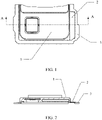
FIG. 1 is a diagram of a partial structure of a decoration according to an embodiment of this application; -
FIG. 2 is an A-A sectional view of the decoration shown inFIG. 1 ; -
FIG. 3 is a sectional view of another decoration according to an embodiment of this application; -
FIG. 4 is a schematic diagram of installation of the decoration shown inFIG. 1 ; -
FIG. 5 is an enlarged diagram of B shown inFIG. 4 ; -
FIG. 6 is a schematic diagram of installation of the decoration shown inFIG. 3 ; -
FIG. 7 is an enlarged diagram of C shown inFIG. 6 ; and -
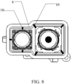
FIG. 8 is a diagram of a partial structure of an electronic device according to an embodiment of this application. - The technical solutions in the embodiments of this application are described below clearly and completely with reference to the accompanying drawings in the embodiments of this application. Apparently, the embodiments described are some rather than all of the embodiments of this application. All other embodiments derived by persons of ordinary skill in the art based on the embodiments of this application without creative efforts fall within the scope of protection of this application.
- The terms such as "first" and "second" in the description and claims of this application are used for distinguishing similar objects, but are not necessarily used for describing a specific sequence or order. It should be understood that the data termed in such a way is interchangeable in proper circumstances so that the embodiments of this application described herein can be implemented in an order other than the order illustrated or described herein. In addition, "first", "second", and the like are generally used to distinguish objects of the same category, rather than to define the number of objects. For example, there may be one object or a plurality of objects. In addition, "and/or" used in the specification and claims means at least one of the connected objects, and the character "/" generally indicates an "or" relationship between the associated objects.
- With reference to the accompanying drawings, a decoration and an electronic device provided in the embodiments of this application are described below in detail by using specific embodiments and application scenarios thereof.
- As shown in
FIG. 1 to FIG. 7 , an embodiment of this application provides a decoration, including: adecorative ring 1 and aflexible fixing member 2, where theflexible fixing member 2 is disposed on an outer surface of thedecorative ring 1, theflexible fixing member 2 extends away from thedecorative ring 1 along a radial direction of thedecorative ring 1, and theflexible fixing member 2 is fixedly connected to thedecorative ring 1. - In this embodiment of this application, the
flexible fixing member 2 may be a foldable or bendable fixing member. Specifically, theflexible fixing member 2 may be made of a flexible material. For example, the flexible fixing member may be an object made of a silicone or plastic material. - In an embodiment of this application, there may be one
flexible fixing member 2 that may be disposed at one end of an annular outer edge of thedecorative ring 1. In another embodiment of this application, there may be two flexible fixing members that are both disposed on the annular outer edge of thedecorative ring 1 and are symmetrical with respect to the center of the decorative ring. - The
flexible fixing member 2 and thedecorative ring 1 may be integrally formed or separately formed. When the flexible fixing member and the decorative ring are integrally formed, the flexible fixing member and the decorative ring cannot be separated, which can improve the reliability of the decorative ring. The flexible fixing member and the decorative ring being separately formed can be more convenient to manufacture and process. - In this embodiment of this application, the flexible fixing member is provided on the outer surface of the decorative ring, and due to deformability of the flexible fixing member, the shape of the flexible fixing member can be adjusted according to the surface shape of the target component, so that when the decoration is assembled into an electronic device, a probability of unevenness of the decoration can be reduced, and the appearance of the electronic device can be improved. For example, when there are too many local components in the electronic device, the components press the flexible fixing member. The flexible fixing member is deformed according to shapes of the components and pressing forces, so as to adapt to the layout of the internal components of the electronic device, thereby reducing the probability of unevenness of the decoration.
- Optionally, a thickness of the
flexible fixing member 2 may be less than a preset thickness. The preset thickness is a skirt thickness of a decoration in common electronic devices. In this way, an assembly space occupied by the decoration can be reduced. In addition, when an assembly position of the flexible fixing member is a bottleneck point in a thickness direction of the electronic device, an overall thickness of the electronic device can also be reduced. - Optionally, the
flexible fixing member 2 is a non-annular flexible fixing member. - Alternatively, the
flexible fixing member 2 is a flexible fixing ring, and the flexible fixing ring encircles the decorative ring. - In an embodiment of this application, when the
flexible fixing member 2 is a non-annular flexible fixing member, theflexible fixing member 2 may be specifically a flexible fixing sheet of various shapes such as a rectangle, a square, a trapezoid, or a circle. In another embodiment of this application, the non-annular flexible fixing member is an annular flexible fixing member having a first gap. The first gap is a gap formed between the outer edge of the decorative ring and the outer edge of the flexible fixing ring. - Since the flexible fixing member is a non-annular flexible fixing member, the assembly space occupied by the flexible fixing member can be reduced in a targeted manner. In some embodiments of this application, the decoration has a non-annular flexible fixing member, and the flexible fixing member is disposed at a position in the electronic device having overlapping components that cause a partial protrusion. The decoration can effectively reduce the production cost while reducing the probability of unevenness of the decoration.
- Optionally, the non-annular flexible fixing member may be an elongated member, and there are two flexible fixing members that are symmetrical with respect to the center of the decorative ring. The two flexible fixing members are disposed at a relatively flat position of the electronic device, so that a position of a non-flexible fixing member of the decorative ring faces a position having a protrusion in the electronic device. In this way, the electronic device has the decoration, and the probability of unevenness of the decoration can be effectively reduced.
- Optionally, the flexible fixing member is an annular flexible fixing member that encircles the decorative ring. Due to the principle that the flexible fixing member is deformable, a height of the entire decorative ring can be adjusted while the entire decorative ring is fixed. This can not only further improve the fixing effect, but can also further reduce the probability of unevenness of the decorative ring.
- Optionally, the decoration further includes a first fixing
member 3. Thefirst fixing member 3 is disposed on a side of theflexible fixing member 2 away from thedecorative ring 1, and the first fixingmember 3 is connected to theflexible fixing member 2. - In the embodiments of this application, the first fixing
member 3 may be specifically a rigid material such as a metal fixing member or a plastic fixing member. Certainly, the first fixing member may also be a flexible fixing member made of a material different from the material of the flexible fixing member. In some embodiments, the material of the flexible fixing member is a soft rubber material, and the material of the first fixing member is a hard rubber material. - The
flexible fixing member 2 and the first fixingmember 3 may be integrally formed or separately formed. When the flexible fixing member and the first fixing member are integrally formed, the decoration can have better reliability due to the inseparability. The flexible fixing member and the first fixing member being separately formed can be more convenient to manufacture and process due to the processing separability. - In some embodiments of this application, the first fixing member is a rigid fixing member. Since the rigid fixing member is further provided on the side of the flexible fixing member away from the decorative ring, the rigid fixing member can reinforce the fixation of the decorative ring, so that the fixing effect can be better.
- Optionally, the first fixing
member 3 is a rigid fixing ring that encircles thedecorative ring 1, and theflexible fixing member 2 is disposed in a first gap between the rigid fixing ring and thedecorative ring 1. - In some optional embodiments, the flexible fixing member is a non-annular flexible fixing member, and the flexible fixing member is disposed in the first gap. The flexible fixing member may be an elongated shape, and there are two flexible fixing members that are symmetrical with respect to the center of the decorative ring. The flexible fixing member is connected to the rigid fixing ring, a protruding component in the electronic device is disposed in the first gap, the protruding component may press against the flexible fixing member, and the protruding component may also be disposed at a position of the first gap that is not the flexible fixing member.
- In some other optional embodiments, the flexible fixing member is an annular flexible fixing member and encircles the decorative ring. The rigid fixing member is disposed at one end of the flexible fixing member away from the decorative ring. In a case that the electronic device has a protruding component, the protruding component may be disposed at the position of the flexible fixing member. Due to the deformability of the flexible fixing member, the probability of unevenness of the decoration can be reduced.
- In the embodiments of this application, the rigid fixing ring may be directly connected to the
decorative ring 1. In some embodiments, the rigid fixing ring may also be connected to thedecorative ring 1 through the flexible fixing ring. For example, as shown inFIG. 3 , when theflexible fixing member 2 is a flexible fixing ring that encircles thedecorative ring 1, the rigid fixing ring may be connected only to the side of the flexible fixing ring away from thedecorative ring 1, so as to be spaced apart from thedecorative ring 1. - Since the rigid fixing member is the rigid fixing ring, a fixation area can be increased, making the fixation of the decoration more convenient. In addition, the rigid fixing ring encircles the decorative ring, and the flexible fixing member is disposed in the first gap between the rigid fixing ring and the decorative ring. This can also provide some protection for the flexible fixing member.
- Optionally, in a case that the
flexible fixing member 2 is a non-annular flexible fixing member, the rigid fixing ring is further connected to the outer surface of thedecorative ring 1. - In this embodiment of this application, in the case that the
flexible fixing member 2 is a non-annular flexible fixing member, the rigid fixing ring being further connected to the outer surface of thedecorative ring 1 may be specifically: in the case that theflexible fixing member 2 is a non-annular flexible fixing member, the side of the rigid fixing ring close to the decorative ring is further connected to the outer surface of thedecorative ring 1, and theflexible fixing member 2 blocks the first gap. - In the case that the flexible fixing member is a non-annular flexible fixing member, the rigid fixing ring is further connected to the outer surface of the decorative ring, so that the rigid fixing ring can directly support and fix the decorative ring. In this way, the fixing effect of the decorative ring can be further improved.
- Optionally, the
flexible fixing member 2 and the first fixingmember 3 are not coplanar. - In the embodiments of this application, the
flexible fixing member 2 and the first fixingmember 3 being not coplanar may mean that the first fixingmember 3 is located below theflexible fixing member 2. - Because the flexible fixing member and the first fixing member are not coplanar, the decoration can be better fixed on a relatively uneven surface.
- Optionally, a limiting
structure 4 is disposed at a joint between theflexible fixing member 2 and thedecorative ring 1. - In the embodiments of this application, the limiting
structure 4 may be various limiting structures such as a limiting buckle or a limiting groove. - Because the limiting structure is disposed at the joint between the flexible fixing member and the decorative ring, the position of the flexible fixing member can be easily defined, the accuracy of a mounting position of the flexible fixing member is improved, and relative movement between the flexible fixing member and the decorative ring can be limited.
- As shown in
FIG. 4 to FIG. 8 , an embodiment of this application further provides an electronic device, including: a decoration described in the foregoing embodiment, ahousing 5, and atarget bracket 6. - The
housing 5 is provided with a through hole and an accommodating cavity that are in communication with each other, a portion of thedecorative ring 1 is disposed in the through hole and a portion of thedecorative ring 1 is disposed in the accommodating cavity, theflexible fixing member 2 and thetarget bracket 6 are both disposed in the accommodating cavity, and theflexible fixing member 2 is located between thehousing 5 and thetarget bracket 6 and is connected to at least one of thehousing 5 and thetarget bracket 6. - In this embodiment of this application, the decoration described in the foregoing embodiment, the housing, and the target bracket are included;
the housing is provided with the through hole and the accommodating cavity that are in communication with each other, a portion of the decorative ring is disposed in the through hole and a portion of the decorative ring is disposed in the accommodating cavity, the flexible fixing member and the target bracket are both disposed in the accommodating cavity, and the flexible fixing member is located between the housing and the target bracket and is connected to at least one of the housing and the target bracket, so that a probability of unevenness of the decoration can be reduced, and the appearance of the electronic device can be improved. - Optionally, the decoration further includes a first fixing
member 3, the first fixingmember 3 is disposed on a side of theflexible fixing member 2 away from thedecorative ring 1, the first fixingmember 3 is connected to theflexible fixing member 2, and theflexible fixing member 2 and the first fixingmember 3 are not coplanar. - The
target bracket 6 is a mainboard bracket. - The electronic device further includes a
first sealing member 7. - The
flexible fixing member 2 is connected to each of thehousing 5 and the mainboard bracket. - The
first fixing member 3 is disposed in the accommodating cavity and between thehousing 5 and the mainboard bracket, the first fixingmember 3 is connected to the mainboard bracket, and thefirst sealing member 7 is disposed in a second gap between the first fixingmember 3 and thehousing 5. - In the embodiments of this application, the
flexible fixing member 2 may be connected to thehousing 5 through a firstadhesive layer 8. Here, the firstadhesive layer 8 may be attached to each of thehousing 5 and theflexible fixing member 2, and the firstadhesive layer 8 may be a self-adhesive, a double-sided adhesive, or a foam adhesive. The connection between theflexible fixing member 2 and the mainboard bracket may mean that the mainboard bracket presses against theflexible fixing member 2. - The
first fixing member 3 may be connected to the mainboard bracket through a secondadhesive layer 9. Here, the secondadhesive layer 9 may be attached to each of the mainboard bracket and the first fixingmember 3, and the secondadhesive layer 9 may be a self-adhesive, a double-sided adhesive, or a foam adhesive. - The decoration further includes the first fixing member, the first fixing member is disposed on a side of the flexible fixing member away from the decorative ring, the first fixing member is connected to the flexible fixing member, and the flexible fixing member and the first fixing member are not coplanar. The target bracket is the mainboard bracket. The electronic device further includes the first sealing member. The flexible fixing member is connected to each of the housing and the mainboard bracket. The first fixing member is disposed in the accommodating cavity and between the housing and the mainboard bracket, the first fixing member is connected to the mainboard bracket, and the first sealing member is disposed in the second gap between the first fixing member and the housing. In this way, the decoration can be more firmly mounted in the electronic device, and the sealing performance of the electronic device can be further improved.
- Optionally, the decoration further includes a first fixing
member 3, the first fixingmember 3 is disposed on a side of theflexible fixing member 2 away from the decorative ring, the first fixingmember 3 is connected to theflexible fixing member 2, and theflexible fixing member 2 and the first fixingmember 3 are not coplanar. - The
target bracket 6 is a camera bracket, and asupport member 10 is disposed on the camera bracket. - The electronic device further includes a
second sealing member 11. - The
flexible fixing member 2 is connected to each of thehousing 5 and thesupport member 10. - The
first fixing member 3 is disposed in the accommodating cavity and between thehousing 5 and the camera bracket, the first fixingmember 3 is connected to the camera bracket, and the second sealingmember 11 is disposed in a third gap between theflexible fixing member 3, the first fixingmember 3, and the camera bracket, and the second sealingmember 11 is disposed adjacent to thesupport member 10. - In the embodiments of this application, the
flexible fixing member 2 may be connected to thehousing 5 through the secondadhesive layer 12. Here, the secondadhesive layer 12 may be attached to each of thehousing 5 and theflexible fixing member 2, and the second adhesive layer 112 may be a self-adhesive, a double-sided adhesive, or a foam adhesive. The connection between theflexible fixing member 2 and thesupport member 10 may mean that thesupport member 10 presses against theflexible fixing member 2. - The
first fixing member 3 may be connected to the camera bracket through a thirdadhesive layer 13. Here, the thirdadhesive layer 13 may be attached to each of the camera bracket and the first fixingmember 3, and the thirdadhesive layer 13 may be a self-adhesive, a double-sided adhesive, or a foam adhesive. - The
support member 10 may be connected to the camera bracket by welding, screw connection, snap connection, or other means. There may be one ormore support members 10. - The decoration further includes the first fixing member, where the first fixing member is disposed on a side of the flexible fixing member away from the decorative ring, the first fixing member is connected to the flexible fixing member, and the flexible fixing member and the first fixing member are not coplanar. The target bracket is the camera bracket, and the support member is disposed on the camera bracket. The electronic device further includes the second sealing member. The flexible fixing member is connected to each of the housing and the support member. The first fixing member is disposed in the accommodating cavity and between the housing and the camera bracket, the first fixing member is connected to the camera bracket, the second sealing member is disposed in the third gap between the flexible fixing member, the first fixing member, and the camera bracket, and the second sealing member is disposed adjacent to the support member. In this way, the decoration can be more firmly mounted in the electronic device, and the sealing performance of the electronic device can be further improved.
- It should be noted that, in this specification, the terms "include", "comprise", or any of their variants are intended to cover a non-exclusive inclusion, so that a process, method, article, or apparatus that includes a series of elements not only includes those elements but also includes other elements that are not expressly listed, or further includes elements inherent to such process, method, article, or apparatus. In the absence of more restrictions, an element defined by "including a " does not exclude other same elements in a process, method, article, or apparatus that includes the element.
- The embodiments of this application are described above with reference to the accompanying drawings, but this application is not limited to the foregoing specific implementations. The foregoing specific implementations are merely illustrative rather than restrictive. Under the enlightenment of this application, persons of ordinary skill in the art may figure out many forms that are not departing from the essence of this application and the scope of protection of the claims. All such forms fall within the protection of this application.
Claims (10)
- A decoration, comprising: a decorative ring and a flexible fixing member, wherein the flexible fixing member is disposed on an outer surface of the decorative ring, the flexible fixing member extends away from the decorative ring along a radial direction of the decorative ring, and the flexible fixing member is fixedly connected to the decorative ring.
- The decoration according to claim 1, wherein the flexible fixing member is a non-annular flexible fixing member; or
the flexible fixing member is a flexible fixing ring, wherein the flexible fixing ring encircles the decorative ring. - The decoration according to claim 1, further comprising a first fixing member, wherein the first fixing member is disposed on a side of the flexible fixing member away from the decorative ring, and the first fixing member is connected to the flexible fixing member.
- The decoration according to claim 3, wherein the first fixing member is a rigid fixing ring that encircles the decorative ring, and the flexible fixing member is disposed in a first gap between the rigid fixing ring and the decorative ring.
- The decoration according to claim 4, wherein in a case that the flexible fixing member is a non-annular flexible fixing member, the rigid fixing ring is further connected to the outer surface of the decorative ring.
- The decoration according to claim 3, wherein the flexible fixing member and the first fixing member are not coplanar.
- The decoration according to claim 1, wherein a limiting structure is disposed at a joint between the flexible fixing member and the decorative ring.
- An electronic device, comprising: the decoration according to any one of claims 1 to 7, a housing, and a target bracket, wherein
the housing is provided with a through hole and an accommodating cavity that are in communication with each other, a portion of the decorative ring is disposed in the through hole and a portion of the decorative ring is disposed in the accommodating cavity, the flexible fixing member and the target bracket are both disposed in the accommodating cavity, and the flexible fixing member is located between the housing and the target bracket and is connected to at least one of the housing and the target bracket. - The electronic device according to claim 8, wherein the decoration further comprises a first fixing member, wherein the first fixing member is disposed on a side of the flexible fixing member away from the decorative ring, the first fixing member is connected to the flexible fixing member, and the flexible fixing member and the first fixing member are not coplanar;the target bracket is a mainboard bracket;the electronic device further comprises a first sealing member;the flexible fixing member is connected to each of the housing and the mainboard bracket; andthe first fixing member is disposed in the accommodating cavity and between the housing and the mainboard bracket, the first fixing member is connected to the mainboard bracket, and the first sealing member is disposed in a second gap between the first fixing member and the housing.
- The electronic device according to claim 8, wherein the decoration further comprises a first fixing member, wherein the first fixing member is disposed on a side of the flexible fixing member away from the decorative ring, the first fixing member is connected to the flexible fixing member, and the flexible fixing member and the first fixing member are not coplanar;the target bracket is a camera bracket, and a support member is disposed on the camera bracket;the electronic device further comprises a second sealing member;the flexible fixing member is connected to each of the housing and the support member; andthe first fixing member is disposed in the accommodating cavity and between the housing and the camera bracket, the first fixing member is connected to the camera bracket, the second sealing member is disposed in a third gap between the flexible fixing member, the first fixing member, and the camera bracket, and the second sealing member is disposed adjacent to the support member.
Applications Claiming Priority (2)
| Application Number | Priority Date | Filing Date | Title |
|---|---|---|---|
| CN202010474670.2A CN111629092A (en) | 2020-05-29 | 2020-05-29 | Decorative Rings and Electronics |
| PCT/CN2021/096698 WO2021239103A1 (en) | 2020-05-29 | 2021-05-28 | Ornament and electronic device |
Publications (2)
| Publication Number | Publication Date |
|---|---|
| EP4161036A1 true EP4161036A1 (en) | 2023-04-05 |
| EP4161036A4 EP4161036A4 (en) | 2023-11-15 |
Family
ID=72260292
Family Applications (1)
| Application Number | Title | Priority Date | Filing Date |
|---|---|---|---|
| EP21811803.2A Pending EP4161036A4 (en) | 2020-05-29 | 2021-05-28 | ORNAMENT AND ELECTRONIC DEVICE |
Country Status (6)
| Country | Link |
|---|---|
| US (2) | US12113919B2 (en) |
| EP (1) | EP4161036A4 (en) |
| JP (1) | JP7493060B2 (en) |
| KR (1) | KR102754532B1 (en) |
| CN (1) | CN111629092A (en) |
| WO (1) | WO2021239103A1 (en) |
Families Citing this family (1)
| Publication number | Priority date | Publication date | Assignee | Title |
|---|---|---|---|---|
| CN111629092A (en) * | 2020-05-29 | 2020-09-04 | 维沃移动通信有限公司 | Decorative Rings and Electronics |
Family Cites Families (22)
| Publication number | Priority date | Publication date | Assignee | Title |
|---|---|---|---|---|
| JP2001215592A (en) * | 2000-01-31 | 2001-08-10 | Canon Inc | Electronics |
| US20090044920A1 (en) * | 2007-08-14 | 2009-02-19 | Angela De Angelis | Magnetic drapery valance ties |
| KR102064596B1 (en) * | 2013-03-11 | 2020-02-11 | 삼성전자 주식회사 | Electronic Device including a camera module |
| CN105346067A (en) * | 2015-11-23 | 2016-02-24 | 广东欧珀移动通信有限公司 | Decorative ring component of mobile equipment and mobile equipment with decorative ring component |
| CN205656637U (en) * | 2016-04-26 | 2016-10-19 | 广东欧珀移动通信有限公司 | Fingerprint identification subassembly, mobile terminal's apron subassembly and mobile terminal |
| CN105872335A (en) * | 2016-05-20 | 2016-08-17 | 深圳天珑无线科技有限公司 | Camera decorating part and mobile terminal |
| CN106095196B (en) * | 2016-08-16 | 2018-09-07 | 广东欧珀移动通信有限公司 | Input components and terminals |
| US10028397B2 (en) * | 2016-09-06 | 2018-07-17 | Apple Inc. | Electronic device with liquid-resistant SIM tray and audio module |
| CN107071240A (en) * | 2016-12-28 | 2017-08-18 | 深圳天珑无线科技有限公司 | A kind of camera decoration coil apparatus and electronic equipment |
| WO2018184289A1 (en) * | 2017-04-06 | 2018-10-11 | 华为技术有限公司 | Fingerprint identification assembly and terminal |
| CN207115276U (en) * | 2017-08-31 | 2018-03-16 | 广东欧珀移动通信有限公司 | Electronic equipment and its rear case component |
| CN207491070U (en) * | 2017-10-17 | 2018-06-12 | 广东欧珀移动通信有限公司 | Camera decoration, housing unit and terminal |
| CN207340024U (en) * | 2017-10-18 | 2018-05-08 | 南京粤讯电子科技有限公司 | Intelligent terminal |
| CN207783372U (en) * | 2018-01-26 | 2018-08-28 | 佳能企业股份有限公司 | Electronic device and stop structure thereof |
| CN108881681B (en) * | 2018-06-28 | 2021-04-06 | Oppo广东移动通信有限公司 | electronic device |
| CN210380949U (en) * | 2019-10-17 | 2020-04-21 | Oppo广东移动通信有限公司 | Housing assembly and electronic device |
| CN110730261A (en) * | 2019-10-28 | 2020-01-24 | Oppo广东移动通信有限公司 | Decorative ring assembly and mobile terminal |
| CN110896419B (en) * | 2019-11-25 | 2021-07-27 | Oppo广东移动通信有限公司 | Housing assembly, mobile terminal and assembly method of decorative parts |
| CN115473989B (en) * | 2019-11-25 | 2024-03-08 | 荣耀终端有限公司 | Camera mounts and electronics |
| CN210578848U (en) * | 2019-11-29 | 2020-05-19 | 维沃移动通信有限公司 | Electronic equipment |
| KR102813625B1 (en) * | 2020-02-10 | 2025-05-29 | 삼성전자주식회사 | Camera assembly and electronic device including the same |
| CN111629092A (en) * | 2020-05-29 | 2020-09-04 | 维沃移动通信有限公司 | Decorative Rings and Electronics |
-
2020
- 2020-05-29 CN CN202010474670.2A patent/CN111629092A/en active Pending
-
2021
- 2021-05-28 WO PCT/CN2021/096698 patent/WO2021239103A1/en not_active Ceased
- 2021-05-28 JP JP2022568992A patent/JP7493060B2/en active Active
- 2021-05-28 KR KR1020227044116A patent/KR102754532B1/en active Active
- 2021-05-28 EP EP21811803.2A patent/EP4161036A4/en active Pending
-
2022
- 2022-11-28 US US18/070,454 patent/US12113919B2/en active Active
-
2024
- 2024-09-10 US US18/830,467 patent/US20240430350A1/en active Pending
Also Published As
| Publication number | Publication date |
|---|---|
| CN111629092A (en) | 2020-09-04 |
| US20240430350A1 (en) | 2024-12-26 |
| WO2021239103A1 (en) | 2021-12-02 |
| US12113919B2 (en) | 2024-10-08 |
| US20230089610A1 (en) | 2023-03-23 |
| KR102754532B1 (en) | 2025-01-14 |
| JP7493060B2 (en) | 2024-05-30 |
| JP2023524885A (en) | 2023-06-13 |
| EP4161036A4 (en) | 2023-11-15 |
| KR20230009989A (en) | 2023-01-17 |
Similar Documents
| Publication | Publication Date | Title |
|---|---|---|
| US20240430350A1 (en) | Decoration and electronic device | |
| JP6247660B2 (en) | Vehicle roof antenna | |
| US10379276B2 (en) | Display device and method for forming the same | |
| US12302501B2 (en) | Curved display module and display device | |
| CN113380145A (en) | Support piece, flexible screen assembly and terminal equipment | |
| EP3483789A1 (en) | Biological identification module and mobile terminal | |
| CN113242341A (en) | Electronic device | |
| CN116830556A (en) | an electronic device | |
| CN107071240A (en) | A kind of camera decoration coil apparatus and electronic equipment | |
| US20150055350A1 (en) | Illumination device and display device | |
| US10965016B2 (en) | Electronic device casing and electronic device | |
| KR102030575B1 (en) | Parts and electronics | |
| CN112929547A (en) | Camera module and electronic equipment | |
| US6311934B1 (en) | Wire harness fixing device | |
| US20110157727A1 (en) | Cover member, lens unit and production method | |
| US7064797B2 (en) | Portable electronic apparatus having curved thin film-type display member | |
| US10345634B2 (en) | Display apparatus | |
| EP3331225B1 (en) | Electronic device shell and electronic device having the same | |
| JPH07336262A (en) | Microphone mounting structure for portable electronic devices | |
| CN107241469B (en) | Decorative ring, cover plate assembly, electronic device and manufacturing method of cover plate assembly | |
| KR20210156602A (en) | Display Apparatus | |
| CN112218187B (en) | Foam protection mechanism and electronic equipment | |
| EP4492571A1 (en) | Antenna device | |
| EP2642589A1 (en) | Film-like member and method for attaching same | |
| US20220234342A1 (en) | Method of attaching elastic protective film on object |
Legal Events
| Date | Code | Title | Description |
|---|---|---|---|
| STAA | Information on the status of an ep patent application or granted ep patent |
Free format text: STATUS: THE INTERNATIONAL PUBLICATION HAS BEEN MADE |
|
| PUAI | Public reference made under article 153(3) epc to a published international application that has entered the european phase |
Free format text: ORIGINAL CODE: 0009012 |
|
| STAA | Information on the status of an ep patent application or granted ep patent |
Free format text: STATUS: REQUEST FOR EXAMINATION WAS MADE |
|
| 17P | Request for examination filed |
Effective date: 20221222 |
|
| AK | Designated contracting states |
Kind code of ref document: A1 Designated state(s): AL AT BE BG CH CY CZ DE DK EE ES FI FR GB GR HR HU IE IS IT LI LT LU LV MC MK MT NL NO PL PT RO RS SE SI SK SM TR |
|
| DAV | Request for validation of the european patent (deleted) | ||
| DAX | Request for extension of the european patent (deleted) | ||
| A4 | Supplementary search report drawn up and despatched |
Effective date: 20231012 |
|
| RIC1 | Information provided on ipc code assigned before grant |
Ipc: H04M 1/02 20060101AFI20231006BHEP |
|
| STAA | Information on the status of an ep patent application or granted ep patent |
Free format text: STATUS: EXAMINATION IS IN PROGRESS |
|
| 17Q | First examination report despatched |
Effective date: 20250912 |
|
| GRAP | Despatch of communication of intention to grant a patent |
Free format text: ORIGINAL CODE: EPIDOSNIGR1 |
|
| STAA | Information on the status of an ep patent application or granted ep patent |
Free format text: STATUS: GRANT OF PATENT IS INTENDED |
|
| INTG | Intention to grant announced |
Effective date: 20260409 |