EP4160976A1 - Low loss routing for quantum communication - Google Patents
Low loss routing for quantum communication Download PDFInfo
- Publication number
- EP4160976A1 EP4160976A1 EP21200138.2A EP21200138A EP4160976A1 EP 4160976 A1 EP4160976 A1 EP 4160976A1 EP 21200138 A EP21200138 A EP 21200138A EP 4160976 A1 EP4160976 A1 EP 4160976A1
- Authority
- EP
- European Patent Office
- Prior art keywords
- quantum
- source
- wavelength
- quantum state
- router
- Prior art date
- Legal status (The legal status is an assumption and is not a legal conclusion. Google has not performed a legal analysis and makes no representation as to the accuracy of the status listed.)
- Granted
Links
Images


Classifications
-
- H—ELECTRICITY
- H04—ELECTRIC COMMUNICATION TECHNIQUE
- H04L—TRANSMISSION OF DIGITAL INFORMATION, e.g. TELEGRAPHIC COMMUNICATION
- H04L9/00—Cryptographic mechanisms or cryptographic arrangements for secret or secure communications; Network security protocols
- H04L9/08—Key distribution or management, e.g. generation, sharing or updating, of cryptographic keys or passwords
- H04L9/0816—Key establishment, i.e. cryptographic processes or cryptographic protocols whereby a shared secret becomes available to two or more parties, for subsequent use
- H04L9/0852—Quantum cryptography
- H04L9/0855—Quantum cryptography involving additional nodes, e.g. quantum relays, repeaters, intermediate nodes or remote nodes
-
- H—ELECTRICITY
- H04—ELECTRIC COMMUNICATION TECHNIQUE
- H04B—TRANSMISSION
- H04B10/00—Transmission systems employing electromagnetic waves other than radio-waves, e.g. infrared, visible or ultraviolet light, or employing corpuscular radiation, e.g. quantum communication
- H04B10/70—Photonic quantum communication
-
- H—ELECTRICITY
- H04—ELECTRIC COMMUNICATION TECHNIQUE
- H04J—MULTIPLEX COMMUNICATION
- H04J14/00—Optical multiplex systems
- H04J14/02—Wavelength-division multiplex systems
- H04J14/0227—Operation, administration, maintenance or provisioning [OAMP] of WDM networks, e.g. media access, routing or wavelength allocation
- H04J14/0254—Optical medium access
- H04J14/0256—Optical medium access at the optical channel layer
-
- H—ELECTRICITY
- H04—ELECTRIC COMMUNICATION TECHNIQUE
- H04J—MULTIPLEX COMMUNICATION
- H04J14/00—Optical multiplex systems
- H04J14/02—Wavelength-division multiplex systems
- H04J14/0227—Operation, administration, maintenance or provisioning [OAMP] of WDM networks, e.g. media access, routing or wavelength allocation
- H04J14/0254—Optical medium access
- H04J14/0267—Optical signaling or routing
-
- H—ELECTRICITY
- H04—ELECTRIC COMMUNICATION TECHNIQUE
- H04L—TRANSMISSION OF DIGITAL INFORMATION, e.g. TELEGRAPHIC COMMUNICATION
- H04L9/00—Cryptographic mechanisms or cryptographic arrangements for secret or secure communications; Network security protocols
- H04L9/08—Key distribution or management, e.g. generation, sharing or updating, of cryptographic keys or passwords
- H04L9/0816—Key establishment, i.e. cryptographic processes or cryptographic protocols whereby a shared secret becomes available to two or more parties, for subsequent use
- H04L9/0852—Quantum cryptography
Definitions
- the present invention provides a method of low loss routing for quantum communication according to the preamble of claim 1 and 2 and a system of low loss routing for quantum communication according to the preamble of claim 11.
- Quantum states of light in particular single photon states allow the transmission of quantum information between users and thus enable secure communication, for example via quantum key distribution (QKD).
- QKD quantum key distribution
- a challenge towards the realization of quantum communication networks is the routing of quantum states to multiple users.
- this object is achieved by a method of low loss routing for quantum communication according to claim 1.
- the object is achieved by a method of low loss routing for quantum communication, comprising a single photon source and/or a weak coherent light source for decoy state quantum key distribution, a router, two or more receivers, and a quantum network connecting each receiver via a quantum channel with the router, whereby the method comprises the steps
- the source comprises a modification means, and the source is connected with the router via a multi-wavelength quantum channel, and the modification means set the wavelength of the generated quantum state in step i) in order to enable a specific allocation of the quantum state in step ii) to a specific quantum channel to a specific receiver, in order to enable a quantum communication between the source and the specific receiver.
- this object is achieved by a method of low loss routing for quantum communication according to claim 2.
- the object is further achieved by a method of low loss routing for quantum communication, comprising an entangled photon pair source, a router, three or more receivers, and a quantum network connecting each receiver via a quantum channel with the source, whereby the method comprises the steps
- the source comprises a modification means, and the source is connected with the router via a multi-wavelength quantum channel, and the modification means set the wavelength of the generated quantum state, preferably of the signal and/or idler photon, in step i) in order to enable a specific allocation of the signal and idler photon in step ii) to two specific quantum channels to two specific receivers, in order to enable a quantum communication between the specific first and the specific second receivers.
- this object is achieved by a system of low loss routing for quantum communication according to claim 11.
- a system of low loss routing for quantum communication comprising
- the source comprises a modification means in order to set the wavelength of the generated quantum state, and the source is connected with the router via a multi-wavelength quantum channel.
- Allocation means here, that the quantum state is redirected or assigned to a quantum channel by the router based on the wavelengths. This means that the spectrum of the quantum state is not split into multiple wavelength bands like in known systems in order to enable a communication between different receivers.
- the advantage by an allocation is the higher communication rates by the use of the whole wavelength spectrum of the quantum state for a communication between the source and the specific receivers or two specific receivers.
- An advantage of the inventive method and system is the high communication rate between two receivers, or the source and one receiver. This is realized by the dynamic generation of the wavelength of the quantum states in the source in addition to the static and thus low loss allocation in the router and the use of the whole spectrum of the photon state.
- An advantage is, that not the network or the allocation means has to be adjusted or changed in order to enable a communication to different receivers, as in known systems, but the allocation is realized by the wavelength depending generation of the quantum state in the source by the modification means.
- the inventive method and system generate a quantum state with a specific wavelength and allocates the quantum state with a specific wavelength to the specific receiver.
- a source with a broad wavelength band is used splitting the broad wavelength band of the quantum state by a wavelength multiplexer into multiple parts which leads to a drastically loss of communication rate between two specific receivers.
- the object is further achieved by a method of low loss routing for quantum communication, according to one of the embodiments above, for a dynamic network with a new receiver.
- the method comprises the additional steps of:
- An advantage of the method for a dynamic network is the ability to add new receiver while not changing the components of the source and the router while still enable the high communication rate of the inventive method and system, even for the new receiver.
- This is realized by the inventive method and system by an allocation of a new wavelength to the new receiver and the ability of the generation of wavelength dependent quantum states by the source and the modification means.
- the components of the source and/or router are changed or a controllable multiplexer is used leading to high losses.
- An advantage of the inventive method and system is, that by adding a new receiver not the whole system for communication has to be changed and adapted, for example by changing the source and the router, but only a new wavelength is allocated to the new receivers and a quantum state with the new wavelength is generated by the source and the modification means.
- the single photon in step i) is generated by a single photon laser, preferably a quantum dot.
- the single photon in step i) is generated by a laser and an attenuator in order to attenuate the generated laser beam to a single photon level.
- the single photon in step i) is generated by a non-linear optical effect, preferably by four-wave-mixing.
- the single photon source is a single photon laser, or a laser and an attenuator in order to generate single photons, or a single photon source by the interaction of a pump laser with a non-linear crystal, preferably by four-wave-mixing in order to generate single photons.
- the weak coherent light pulse in step i) is generated by a laser and an attenuator in order to attenuate the generated laser beam to the weak coherent light pulse.
- the weak coherent light source is a laser and an attenuator in order to generate the weak coherent light pulse.
- the laser and the attenuator can be used as the single photon source and/or the weak coherent light source for example by generating single photons by driving the laser at a low power level, or by generating a weak coherent light pulse by driving the laser to various higher power levels or change the attenuation of the attenuator.
- the entangled photon pair in step i) is generated by a non-linear optical effect, preferably by four-wave-mixing or by down-conversion, preferably by spontaneous parametric down conversion.
- the entangle photon pair source is a parametric down-conversion source or a four-wave mixing source comprising a pump laser and a non-linear crystal.
- the modification means for the single photon source and/or the weak coherent light source is an adjustable optical cavity, whereby the source is located in or in front of the optical cavity.
- the set of the wavelength by the modification means for the single photon source and/or the weak coherent light source in step i) is realized by an adjustable optical cavity.
- the modification means for the single photon source is an adjustable heater or adjustable cooler for the laser generating the single photons and/or the weak coherent light pulse.
- the set of the wavelength by the modification means for the single photon source and/or the weak coherent light source in step i) is realized by set of the temperature of the laser of the source enable the source to generate a photon with the wavelength for the specific receiver.
- the modification means for the single photon source is an adjustable pump laser for the four-wave-mixing, and/or an adjustable heater or adjustable cooler for the non-linear crystal for four-wave-mixing in order to generate single photons.
- the set of the wavelength by the modification means for the single photon source in step i) is realized by set of the pump wavelength by an adjustable pump laser for four-wave-mixing, and/or by set of the temperature of the non-linear crystal for four-wave-mixing in order to generate single photons.
- the advantage of this embodiments is the precise adjustment of the wavelength of the generated quantum state.
- the modification means for the single photon source and/or the weak coherent light source is a dispersive element, preferably a reflective or transitive dispersive element, more preferably a grating, and/or a diffraction grating, and/or a filter, and/or a Bragg grating.
- the dispersive element is arranged in or behind the source.
- the set of the wavelength by the modification means for the single photon source and/or the weak coherent light source in step i) is realized by a dispersive element.
- the modification means for the entangled photon source is an adjustable pump laser of the source for pumping a non-linear crystal for down-conversion or for four-wave-mixing.
- the modification means for the entangled photon source is an adjustable heater or adjustable cooler for the non-linear crystal or for the pump laser.
- the set of the wavelength for the entangled photon source in step i) is realized by set of the pump wavelength for the non-linear crystal by an adjustable pump laser for down-conversion or four-wave-mixing or is realized by set of the temperature of the non-linear crystal for down-conversion or four-wave-mixing.
- Down-conversion or four-wave-mixing are nonlinear optical effects, whereby the interaction of the non-linear crystal with one or two wavelengths produces photons with new wavelengths.
- the wavelengths of the generated photons are dependent on the phase matching condition in these non-linear processes, for example dependent on the pump wavelength and/or on the temperature of the non-linear crystal.
- An advantage of this embodiment is the wavelength dependent generation of both photons of the entangled photon pair.
- the modification means for the entangled photon source, and/or the single photon source, and/or the weak coherent light source is an acousto-optic modulator, and/or an electro-optic modulator, and/or a phase modulator, and/or a Lithium niobate (LN) phase modulator in the source in order to realize a frequency shift of a generated photon in the source by a linear phase ramp of the modulator.
- LN Lithium niobate
- the set of the wavelength for the entangled photon source, and/or the single photon source, and/or the weak coherent light source in step i) is realized by a frequency shift of the wavelength of the quantum state due to a phase modulation of the quantum state, preferably by a linear phase ramp of the modulator.
- the modification means influences the wavelength in the generation process of the quantum state in the source or influences the wavelength by a change of the wavelength of the generated quantum state in the source.
- the first case can for example be realized by a single photon laser with an adjustable optical cavity or a temperature means, or by an entangled photon source by changing the pump wavelength and/or the temperature of the non-linear crystal. That means the modification means is a component of the source influencing the wavelength of the quantum state in the generation process.
- the second case can for example be realized by one of the modulators mentioned above in a single photon source or an entangled photon pair source. That means the modification means is a component of the source influencing the wavelength of the quantum state after the generation process.
- the wavelength bandwidth of the quantum state of the source is smaller as the wavelength bandwidth of the channels of the router, preferably smaller as the wavelength bandwidth of each channel of the router.
- the wavelength bandwidth of the generated single photons, or weak coherent light pulse, or signal photon and idler photon is smaller as the wavelength bandwidth of the channels of the router.
- the system comprises a control means, whereas control means set the wavelength of the quantum state in order to allow a communication between the source and one specific receiver, or between two specific receivers.
- control means set the wavelength of the quantum state in order to allow a communication between the source and one specific receiver, or between two specific receivers.
- the source, and/or the modification means is controlled by the control means.
- the whole wavelength bandwidth of the source is used for the communication between the source and one specific receiver, or between two specific receivers.
- the advantage of this embodiment is the higher transmission rates by the use of the whole wavelength bandwidth.
- the allocation in step ii) is a realized by static routing.
- the router is a static router. Static means here, that the routing is not realized by a switch or a movable or changeable element, but by a fixed and/or determined spatial separation of the quantum state according to its wavelength. The advantage of that embodiment is the lower cost of the router and the higher transmission rate in the router.
- the router is a grating, preferably a in fiber grating or a free space grating, preferably a Bragg grating.
- the allocation in step ii) is a realized by diffraction.
- the router is a diffractive optical element.
- the quantum channels are guided channels, preferably fiber channels or the quantum channels are unguided channels, preferably free space channels.
- the transmission is realized by guidance of the quantum state in a guided quantum channel, preferably in a fiber.
- the transmission is realized by the alignment of the quantum state at the router and a unguided transmission in an unguided channel, preferably in a free space channel.
- the router is a diffractive optical element in order to split a broad spectral bandwidth into multiple spectral channel-bandwidths and a mirror or a mirror system, and/or a lens or a lens system.
- the diffractive optical element realizes the wavelength separation, the mirror or lens system realizes the alignment or guidance of the quantum state in order to transmit the quantum state in an un-guided channel.
- Add a new channel for a guided channel means, that the router is connected with the channel.
- Add a new channel for an unguided channel means, that the router is adjusted in order to enable a transmission of the quantum state towards the new receivers by alignment.
- This adjustment can be realized for example by a diffractive optical element, and/or a mirror or mirror system, and/or lens or lens system.
- the detection in step iv) is realized by a measurement means and a detection means, whereby the measurement means set the property to be measured and the detection means detect the photon.
- a property to be measured for the communication could be for example the polarization, and/or the time, and/or orbital angular momentum (OAM) or spin angular momentum (SAM).
- the entangled photon state is entangled in the polarization, and/or the time, and/or orbital angular momentum (OAM) or spin angular momentum (SAM).
- the measurement means comprises a polarizer, and/or a polarizing beam splitter, and/or an electro-optical modulator, and/or an acousto-optic modulator, and/or one or more waveplates, and/or an interferometer, and/or a Spatial Light Modulator.
- the detection means is a single photon detector, preferably germanium (Ge), or silicon (Si), or germanium on silicon (Ge on Si) single-photon avalanche diode (SPAD), or Indium gallium arsenide (InGaAs/Inp) single photon detectors, or semiconductor-based single-photon avalanche diode (SPAD), or superconducting nanowire single-photon detector (SNSPD), or Silicon Avalanche Photodiodes (Si APD).
- a single photon detector preferably germanium (Ge), or silicon (Si), or germanium on silicon (Ge on Si) single-photon avalanche diode (SPAD), or Indium gallium arsenide (InGaAs/Inp) single photon detectors, or semiconductor-based single-photon avalanche diode (SPAD), or superconducting nanowire single-photon detector (SNSPD), or Silicon Avalanche Photodiodes (Si APD
- the detection means comprise one or more detectors to measure the photons in at least two mutually unbiased measurement bases, and/or to measure the photons in at least one or more orthogonal states.
- Fig. 1 shows the inventive system for low loss routing for quantum communication comprising a source 1 with a modification means 2, a router 3, a quantum network connecting each receiver 5 via a quantum channel 4 with the source 1.
- the source 1 in Fig. 1 can be a single photon source, and/or a weak coherent light source, or an entangled photon source.
- the source 1 generates a quantum state, whereby the wavelength of the quantum state is set by the modification means 2 and the source 1.
- the quantum state of the single photon source is a single photon.
- the quantum state of the weak coherent light source is a weak coherent light pulse.
- the quantum state of the entangled photon source is an entangled photon pair. The quantum state is then guided via a multi-wavelength channel 6 from the source 1 to the router 3.
- Set the wavelength of the generated quantum state means here, that the modification means 2 influences the wavelength in the generation process of the quantum state in the source 1 or influences the wavelength by a change of the wavelength of the quantum state in the source 1.
- the modification means 2 for the single photon source and/or the weak coherent light source can be an adjustable optical cavity, or an adjustable heater or adjustable cooler for the laser generating the single photons or the weak coherent light pulse, or an adjustable pump laser for the four-wave-mixing, and/or an adjustable heater or adjustable cooler for the non-linear crystal for four-wave-mixing, or a dispersive element, or an acousto-optic modulator, and/or an electro-optic modulator, and/or a phase modulator, and/or a Lithium niobate (LN) phase modulator.
- an adjustable optical cavity or an adjustable heater or adjustable cooler for the laser generating the single photons or the weak coherent light pulse
- an adjustable pump laser for the four-wave-mixing
- an adjustable heater or adjustable cooler for the non-linear crystal for four-wave-mixing
- a dispersive element or an acousto-optic modulator, and/or an electro-optic modulator, and/or a phase modul
- the modification means 2 for the entangled photon source can be an adjustable pump laser of the source for pumping a non-linear crystal for down-conversion or for four-wave-mixing, or adjustable heater or adjustable cooler for the non-linear crystal or for the pump laser, or an acousto-optic modulator, and/or an electro-optic modulator, and/or a phase modulator, and/or a Lithium niobate (LN) phase modulator.
- an adjustable pump laser of the source for pumping a non-linear crystal for down-conversion or for four-wave-mixing
- adjustable heater or adjustable cooler for the non-linear crystal or for the pump laser
- an acousto-optic modulator and/or an electro-optic modulator, and/or a phase modulator, and/or a Lithium niobate (LN) phase modulator.
- LN Lithium niobate
- the router 3 allocates the quantum state according to the wavelength of the quantum state to a specific quantum channel 4 in order to transmit the quantum state to a specific receiver 5, or in the case of an entangled photon pair to two specific receivers 5.
- the allocation is realized by a fixed correlation of the output of the router 3 with each quantum channel 4 and by a fixed redirection of the quantum state according to its wavelength in the router 3.
- Fig. 1 three receivers 5 are connected via the quantum channels 4 with the router 3 depicted by the solid lines.
- a new receiver 5 can be added to the network via a new quantum channel 4 depicted by dashed lines, without changing any components in the router 3 or the source 1.
- the communication to the new receiver 5 (dashed) is realized by the generation of the quantum state in the source 1 with the new wavelength by the source 1 and the modification means 2.
- Fig. 2 shows an example of the influence of the modification means 2 on the wavelength of a quantum state as a single photon.
- the solid line shows the wavelength spectrum of a generated quantum state, in the case of Fig. 2 for the quantum channel C3.
- the wavelength bandwidth of the quantum state of the source 1 is smaller than the wavelength bandwidth of the channels of the router 3.
- the communication with quantum channel C4 should be realized.
- modification means 2 and the source 1 generate by the influence of the modification means 2 the quantum states with a wavelength spectrum for quantum channel 4 C4 as depicted by the dashed line.
- Fig. 3 shows an example of the influence of the modification means 2 on the wavelength of a quantum state as an entangled photon pair.
- the wavelengths of the generated photons are dependent on the phase matching condition in non-linear processes like down-conversion or four wave mixing, for example dependent on the pump wavelength and/or on the temperature of the non-linear crystal.
- Fig. 3 shows the symmetric shift by the phase matching conditions of the signal photon in quantum channel C s 1 and the idler photon in quantum channel C i 1 toward the quantum channels C s 3 and C i 3 by the influence of the modification means 2 on the source 1.
- the modification means 2 is influencing the generation of the entangled photon pair and thus the wavelength of both entangled photons.
- This can be realized by the modification means 2 as an adjustable pump laser of the source for pumping a non-linear crystal for down-conversion or for four-wave-mixing, or an adjustable heater or an adjustable cooler for the non-linear crystal or for the pump laser. It is also possible to set the wavelength for both photons of an entangled photon pair separate by an acousto-optic modulator, and/or an electro-optic modulator, and/or a phase modulator, and/or a Lithium niobate (LN) phase modulator for each photon.
- LN Lithium niobate
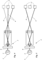
- Fig. 4 and 5 show the inventive system with a router 3 as a diffractive optical element and a lens system.
- the diffractive optical element realizes the wavelength separation, lens system realizes the alignment or guidance of the quantum state in order to transmit the quantum state in an un-guided quantum channel 4 to the receivers 5.
- an additional receiver 5 (dashed) can be added to the network for a communication between the new receiver 5 and an already existing receiver 5 ( Fig. 5 ), by the generation of a quantum state with a new wavelength in the source 1 and the modification means 2 and an allocation of the quantum state according to its wavelength to the new receiver 5.
Landscapes
- Engineering & Computer Science (AREA)
- Computer Networks & Wireless Communication (AREA)
- Signal Processing (AREA)
- Physics & Mathematics (AREA)
- Electromagnetism (AREA)
- Theoretical Computer Science (AREA)
- Computer Security & Cryptography (AREA)
- Optics & Photonics (AREA)
- Optical Modulation, Optical Deflection, Nonlinear Optics, Optical Demodulation, Optical Logic Elements (AREA)
- Optical Communication System (AREA)
- Data Exchanges In Wide-Area Networks (AREA)
Abstract
Description
- The present invention provides a method of low loss routing for quantum communication according to the preamble of
claim - Quantum states of light, in particular single photon states allow the transmission of quantum information between users and thus enable secure communication, for example via quantum key distribution (QKD). A challenge towards the realization of quantum communication networks is the routing of quantum states to multiple users.
- The majority of known quantum communication systems in networks is static and point to point from the source to a particular receiver, with the disadvantage that the system cannot be adapted or changed, for example in order to add new receivers. In static networks the routing is realized by a source with a broad wavelength spectrum, multiplexing of this broad spectrum into small wavelength-bands for the receivers and a fixed assignment of the wavelength-bands to the receivers. The broad spectrum of the source is split according to the number of receivers leading to a low single photon rate transmitted to each receiver and thus to a low communication rate in the case of multiple receivers.
- In known dynamic network systems where receivers can be added or removed electrically controlled optical routers are used with the disadvantage of high losses.
- It is an object of the present invention to provide a more flexible, improved, and cost-efficient method and system for quantum communication with a high communication bandwidth.
- According to the present invention this object is achieved by a method of low loss routing for quantum communication according to
claim 1. - The object is achieved by a method of low loss routing for quantum communication, comprising a single photon source and/or a weak coherent light source for decoy state quantum key distribution, a router, two or more receivers, and a quantum network connecting each receiver via a quantum channel with the router, whereby the method comprises the steps
- i) generation of a quantum state in the source and transmission of the quantum state to the router, whereby the quantum state is a single photon and/or a weak coherent light pulse;
- ii) allocation of the quantum state based on the wavelength of the quantum state to a quantum channel by the router;
- iii) transmission of the quantum state via the quantum channel to a receiver;
- iv) detection of the quantum state at the receiver in order to establish a quantum communication between the source and the receiver;
- According to the invention the source comprises a modification means, and the source is connected with the router via a multi-wavelength quantum channel, and the modification means set the wavelength of the generated quantum state in step i) in order to enable a specific allocation of the quantum state in step ii) to a specific quantum channel to a specific receiver, in order to enable a quantum communication between the source and the specific receiver.
- According to the present invention this object is achieved by a method of low loss routing for quantum communication according to
claim 2. - The object is further achieved by a method of low loss routing for quantum communication, comprising an entangled photon pair source, a router, three or more receivers, and a quantum network connecting each receiver via a quantum channel with the source, whereby the method comprises the steps
- i) generation of a quantum state in the source and transmission of the quantum state to the router, whereby the quantum state is an entangled photon pair with a signal photon and an idler photon;
- ii) allocation of the quantum state based on the wavelengths of the signal photon to a first quantum channel and the idler photon to a second quantum channel by the router;
- iii) transmission of the quantum state via the quantum channels to the two receivers, preferably a first and a second receiver;
- iv) detection of the quantum state at the two receivers in order to establish a quantum communication between the two receivers.
- According to the invention the source comprises a modification means, and the source is connected with the router via a multi-wavelength quantum channel, and the modification means set the wavelength of the generated quantum state, preferably of the signal and/or idler photon, in step i) in order to enable a specific allocation of the signal and idler photon in step ii) to two specific quantum channels to two specific receivers, in order to enable a quantum communication between the specific first and the specific second receivers.
- According to the present invention this object is achieved by a system of low loss routing for quantum communication according to claim 11.
- The object is further achieved by a system of low loss routing for quantum communication, comprising
- a source for the generation of a quantum state, preferably a single photon source, and/or a weak coherent light source for decoy state quantum key distribution, or an entangled photon pair source, and
- a router for the allocation of the quantum state to one or more quantum channels based on the wavelength of the quantum state, and
- a quantum network connecting each receiver via a quantum channel with the source for the transmission of the quantum state, and
- two or more receivers for the detection of the quantum state.
- According to the invention the source comprises a modification means in order to set the wavelength of the generated quantum state, and
the source is connected with the router via a multi-wavelength quantum channel. - Allocation means here, that the quantum state is redirected or assigned to a quantum channel by the router based on the wavelengths. This means that the spectrum of the quantum state is not split into multiple wavelength bands like in known systems in order to enable a communication between different receivers. The advantage by an allocation is the higher communication rates by the use of the whole wavelength spectrum of the quantum state for a communication between the source and the specific receivers or two specific receivers.
- An advantage of the inventive method and system is the high communication rate between two receivers, or the source and one receiver. This is realized by the dynamic generation of the wavelength of the quantum states in the source in addition to the static and thus low loss allocation in the router and the use of the whole spectrum of the photon state. An advantage is, that not the network or the allocation means has to be adjusted or changed in order to enable a communication to different receivers, as in known systems, but the allocation is realized by the wavelength depending generation of the quantum state in the source by the modification means.
- The inventive method and system generate a quantum state with a specific wavelength and allocates the quantum state with a specific wavelength to the specific receiver. In contrast to this in known systems a source with a broad wavelength band is used splitting the broad wavelength band of the quantum state by a wavelength multiplexer into multiple parts which leads to a drastically loss of communication rate between two specific receivers.
- The object is further achieved by a method of low loss routing for quantum communication, according to one of the embodiments above, for a dynamic network with a new receiver. According to the invention before the steps i) to iv) according to one of the embodiments above, the method comprises the additional steps of:
- a) addition of a new receiver to the network by connecting the router with the new receiver via a new quantum channel;
- b) allocation of a new wavelength in the router for the new receiver;
- c) step i) to iv) according to one of the embodiments above with a quantum state with the new wavelength by the modification means in order to establish a communication between the source and the new receiver or between a specific receiver and the new receiver.
- An advantage of the method for a dynamic network is the ability to add new receiver while not changing the components of the source and the router while still enable the high communication rate of the inventive method and system, even for the new receiver. This is realized by the inventive method and system by an allocation of a new wavelength to the new receiver and the ability of the generation of wavelength dependent quantum states by the source and the modification means. In known systems for dynamic networks either the components of the source and/or router are changed or a controllable multiplexer is used leading to high losses. An advantage of the inventive method and system is, that by adding a new receiver not the whole system for communication has to be changed and adapted, for example by changing the source and the router, but only a new wavelength is allocated to the new receivers and a quantum state with the new wavelength is generated by the source and the modification means.
- In a preferred embodiment, the single photon in step i) is generated by a single photon laser, preferably a quantum dot. In a preferred embodiment, the single photon in step i) is generated by a laser and an attenuator in order to attenuate the generated laser beam to a single photon level. In a preferred embodiment, the single photon in step i) is generated by a non-linear optical effect, preferably by four-wave-mixing. In a preferred embodiment, the single photon source is a single photon laser, or a laser and an attenuator in order to generate single photons, or a single photon source by the interaction of a pump laser with a non-linear crystal, preferably by four-wave-mixing in order to generate single photons.
- In a preferred embodiment, the weak coherent light pulse in step i) is generated by a laser and an attenuator in order to attenuate the generated laser beam to the weak coherent light pulse. In a preferred embodiment, the weak coherent light source is a laser and an attenuator in order to generate the weak coherent light pulse. The laser and the attenuator can be used as the single photon source and/or the weak coherent light source for example by generating single photons by driving the laser at a low power level, or by generating a weak coherent light pulse by driving the laser to various higher power levels or change the attenuation of the attenuator.
- In a preferred embodiment, the entangled photon pair in step i) is generated by a non-linear optical effect, preferably by four-wave-mixing or by down-conversion, preferably by spontaneous parametric down conversion. In a preferred embodiment, the entangle photon pair source is a parametric down-conversion source or a four-wave mixing source comprising a pump laser and a non-linear crystal.
- In a preferred embodiment, the modification means for the single photon source and/or the weak coherent light source is an adjustable optical cavity, whereby the source is located in or in front of the optical cavity. In a preferred embodiment, the set of the wavelength by the modification means for the single photon source and/or the weak coherent light source in step i) is realized by an adjustable optical cavity. The advantage of this embodiments is the precise wavelength modification, the small wavelength bandwidth of the generated quantum state, and that the source inside the optical cavity is excited to emit photons only in the desired wavelength leading to a higher emission rate. The small wavelength bandwidth enables the allocation of the wavelength in a very precise way without losses.
- In a preferred embodiment, the modification means for the single photon source is an adjustable heater or adjustable cooler for the laser generating the single photons and/or the weak coherent light pulse. In a preferred embodiment, the set of the wavelength by the modification means for the single photon source and/or the weak coherent light source in step i) is realized by set of the temperature of the laser of the source enable the source to generate a photon with the wavelength for the specific receiver. The advantage of this embodiments is the cheap and cost-efficient implementation of the modification means.
- In a preferred embodiment, the modification means for the single photon source is an adjustable pump laser for the four-wave-mixing, and/or an adjustable heater or adjustable cooler for the non-linear crystal for four-wave-mixing in order to generate single photons. In a preferred embodiment, the set of the wavelength by the modification means for the single photon source in step i) is realized by set of the pump wavelength by an adjustable pump laser for four-wave-mixing, and/or by set of the temperature of the non-linear crystal for four-wave-mixing in order to generate single photons. The advantage of this embodiments is the precise adjustment of the wavelength of the generated quantum state.
- In a preferred embodiment, the modification means for the single photon source and/or the weak coherent light source is a dispersive element, preferably a reflective or transitive dispersive element, more preferably a grating, and/or a diffraction grating, and/or a filter, and/or a Bragg grating. In a preferred embodiment, the dispersive element is arranged in or behind the source. In a preferred embodiment, the set of the wavelength by the modification means for the single photon source and/or the weak coherent light source in step i) is realized by a dispersive element. The advantage of this embodiments are the low costs and the precise wavelengths modification possibilities.
- In a preferred embodiment, the modification means for the entangled photon source is an adjustable pump laser of the source for pumping a non-linear crystal for down-conversion or for four-wave-mixing. In a preferred embodiment, the modification means for the entangled photon source is an adjustable heater or adjustable cooler for the non-linear crystal or for the pump laser. In a preferred embodiment, the set of the wavelength for the entangled photon source in step i) is realized by set of the pump wavelength for the non-linear crystal by an adjustable pump laser for down-conversion or four-wave-mixing or is realized by set of the temperature of the non-linear crystal for down-conversion or four-wave-mixing. Down-conversion or four-wave-mixing are nonlinear optical effects, whereby the interaction of the non-linear crystal with one or two wavelengths produces photons with new wavelengths. The wavelengths of the generated photons are dependent on the phase matching condition in these non-linear processes, for example dependent on the pump wavelength and/or on the temperature of the non-linear crystal. An advantage of this embodiment is the wavelength dependent generation of both photons of the entangled photon pair.
- In a preferred embodiment, the modification means for the entangled photon source, and/or the single photon source, and/or the weak coherent light source is an acousto-optic modulator, and/or an electro-optic modulator, and/or a phase modulator, and/or a Lithium niobate (LN) phase modulator in the source in order to realize a frequency shift of a generated photon in the source by a linear phase ramp of the modulator. In a preferred embodiment, the set of the wavelength for the entangled photon source, and/or the single photon source, and/or the weak coherent light source in step i) is realized by a frequency shift of the wavelength of the quantum state due to a phase modulation of the quantum state, preferably by a linear phase ramp of the modulator. An advantage of this embodiment is the possibility of a separate wavelength change of each photon of the quantum state behind the pair production step in the source.
- Set the wavelength of the generated quantum state means here, that the modification means influences the wavelength in the generation process of the quantum state in the source or influences the wavelength by a change of the wavelength of the generated quantum state in the source. The first case can for example be realized by a single photon laser with an adjustable optical cavity or a temperature means, or by an entangled photon source by changing the pump wavelength and/or the temperature of the non-linear crystal. That means the modification means is a component of the source influencing the wavelength of the quantum state in the generation process. The second case can for example be realized by one of the modulators mentioned above in a single photon source or an entangled photon pair source. That means the modification means is a component of the source influencing the wavelength of the quantum state after the generation process.
- In a preferred embodiment, the wavelength bandwidth of the quantum state of the source is smaller as the wavelength bandwidth of the channels of the router, preferably smaller as the wavelength bandwidth of each channel of the router. In a preferred embodiment, the wavelength bandwidth of the generated single photons, or weak coherent light pulse, or signal photon and idler photon is smaller as the wavelength bandwidth of the channels of the router. The advantage of this embodiment is that no photons are lost in the router by the allocation of the quantum states according to the wavelength to the intended receivers for the quantum communication. In contrast to that, in known systems the bandwidth of the source is split into multiple parts for multiple receivers introducing high losses, reducing the communication bandwidth by the losses and the number of the receivers.
- In a preferred embodiment, the system comprises a control means, whereas control means set the wavelength of the quantum state in order to allow a communication between the source and one specific receiver, or between two specific receivers. In a preferred embodiment, the source, and/or the modification means is controlled by the control means.
- In a preferred embodiment, the whole wavelength bandwidth of the source is used for the communication between the source and one specific receiver, or between two specific receivers. The advantage of this embodiment is the higher transmission rates by the use of the whole wavelength bandwidth.
- In a preferred embodiment, the allocation in step ii) is a realized by static routing. In a preferred embodiment, the router is a static router. Static means here, that the routing is not realized by a switch or a movable or changeable element, but by a fixed and/or determined spatial separation of the quantum state according to its wavelength. The advantage of that embodiment is the lower cost of the router and the higher transmission rate in the router.
- In a preferred embodiment, the router is a grating, preferably a in fiber grating or a free space grating, preferably a Bragg grating.
- In a preferred embodiment, the allocation in step ii) is a realized by diffraction. In a preferred embodiment, the router is a diffractive optical element.
- In a preferred embodiment, the quantum channels are guided channels, preferably fiber channels or the quantum channels are unguided channels, preferably free space channels. In a preferred embodiment, in step iii) the transmission is realized by guidance of the quantum state in a guided quantum channel, preferably in a fiber. In a preferred embodiment, in step iii) the transmission is realized by the alignment of the quantum state at the router and a unguided transmission in an unguided channel, preferably in a free space channel.
- In a preferred embodiment, the router is a diffractive optical element in order to split a broad spectral bandwidth into multiple spectral channel-bandwidths and a mirror or a mirror system, and/or a lens or a lens system. The diffractive optical element realizes the wavelength separation, the mirror or lens system realizes the alignment or guidance of the quantum state in order to transmit the quantum state in an un-guided channel.
- Add a new channel for a guided channel means, that the router is connected with the channel. Add a new channel for an unguided channel means, that the router is adjusted in order to enable a transmission of the quantum state towards the new receivers by alignment. This adjustment can be realized for example by a diffractive optical element, and/or a mirror or mirror system, and/or lens or lens system.
- In a preferred embodiment, the detection in step iv) is realized by a measurement means and a detection means, whereby the measurement means set the property to be measured and the detection means detect the photon. A property to be measured for the communication could be for example the polarization, and/or the time, and/or orbital angular momentum (OAM) or spin angular momentum (SAM). In a preferred embodiment, the entangled photon state is entangled in the polarization, and/or the time, and/or orbital angular momentum (OAM) or spin angular momentum (SAM).
- In a preferred embodiment, the measurement means comprises a polarizer, and/or a polarizing beam splitter, and/or an electro-optical modulator, and/or an acousto-optic modulator, and/or one or more waveplates, and/or an interferometer, and/or a Spatial Light Modulator.
- In a preferred embodiment, the detection means is a single photon detector, preferably germanium (Ge), or silicon (Si), or germanium on silicon (Ge on Si) single-photon avalanche diode (SPAD), or Indium gallium arsenide (InGaAs/Inp) single photon detectors, or semiconductor-based single-photon avalanche diode (SPAD), or superconducting nanowire single-photon detector (SNSPD), or Silicon Avalanche Photodiodes (Si APD).
- In a preferred embodiment, the detection means comprise one or more detectors to measure the photons in at least two mutually unbiased measurement bases, and/or to measure the photons in at least one or more orthogonal states.
- The above and other aspects, features and advantages of the present invention will become more apparent from the following detailed description when taken in conjunction with the accompanying drawings.
-
- Fig. 1:
- schematic diagram of the inventive system for low loss routing;
- Fig. 2:
- schematic diagram of the influence of the modification means on the wavelength of a single photon;
- Fig. 3:
- schematic diagram of the influence of the modification means on the wavelength of a photon pair;
- Fig. 4:
- schematic diagram of the inventive system with a diffractive optical element and lens system as a modification means;
- Fig. 5:
- change of the channel for the inventive system from
Fig. 4 . -
Fig. 1 shows the inventive system for low loss routing for quantum communication comprising asource 1 with a modification means 2, arouter 3, a quantum network connecting eachreceiver 5 via aquantum channel 4 with thesource 1. - The
source 1 inFig. 1 can be a single photon source, and/or a weak coherent light source, or an entangled photon source. Thesource 1 generates a quantum state, whereby the wavelength of the quantum state is set by the modification means 2 and thesource 1. The quantum state of the single photon source is a single photon. The quantum state of the weak coherent light source is a weak coherent light pulse. The quantum state of the entangled photon source is an entangled photon pair. The quantum state is then guided via amulti-wavelength channel 6 from thesource 1 to therouter 3. - Set the wavelength of the generated quantum state means here, that the modification means 2 influences the wavelength in the generation process of the quantum state in the
source 1 or influences the wavelength by a change of the wavelength of the quantum state in thesource 1. - The modification means 2 for the single photon source and/or the weak coherent light source can be an adjustable optical cavity, or an adjustable heater or adjustable cooler for the laser generating the single photons or the weak coherent light pulse, or an adjustable pump laser for the four-wave-mixing, and/or an adjustable heater or adjustable cooler for the non-linear crystal for four-wave-mixing, or a dispersive element, or an acousto-optic modulator, and/or an electro-optic modulator, and/or a phase modulator, and/or a Lithium niobate (LN) phase modulator.
- The modification means 2 for the entangled photon source can be an adjustable pump laser of the source for pumping a non-linear crystal for down-conversion or for four-wave-mixing, or adjustable heater or adjustable cooler for the non-linear crystal or for the pump laser, or an acousto-optic modulator, and/or an electro-optic modulator, and/or a phase modulator, and/or a Lithium niobate (LN) phase modulator.
- The
router 3 allocates the quantum state according to the wavelength of the quantum state to a specificquantum channel 4 in order to transmit the quantum state to aspecific receiver 5, or in the case of an entangled photon pair to twospecific receivers 5. The allocation is realized by a fixed correlation of the output of therouter 3 with eachquantum channel 4 and by a fixed redirection of the quantum state according to its wavelength in therouter 3. - As shown in
Fig. 1 threereceivers 5 are connected via thequantum channels 4 with therouter 3 depicted by the solid lines. Anew receiver 5 can be added to the network via a newquantum channel 4 depicted by dashed lines, without changing any components in therouter 3 or thesource 1. The communication to the new receiver 5 (dashed) is realized by the generation of the quantum state in thesource 1 with the new wavelength by thesource 1 and the modification means 2. -
Fig. 2 shows an example of the influence of the modification means 2 on the wavelength of a quantum state as a single photon. The solid line shows the wavelength spectrum of a generated quantum state, in the case ofFig. 2 for the quantum channel C3. The wavelength bandwidth of the quantum state of thesource 1 is smaller than the wavelength bandwidth of the channels of therouter 3. In a new step the communication with quantum channel C4 should be realized. - For that the modification means 2 and the
source 1 generate by the influence of the modification means 2 the quantum states with a wavelength spectrum forquantum channel 4 C4 as depicted by the dashed line. -
Fig. 3 shows an example of the influence of the modification means 2 on the wavelength of a quantum state as an entangled photon pair. The wavelengths of the generated photons are dependent on the phase matching condition in non-linear processes like down-conversion or four wave mixing, for example dependent on the pump wavelength and/or on the temperature of the non-linear crystal.Fig. 3 shows the symmetric shift by the phase matching conditions of the signal photon inquantum channel C s1 and the idler photon inquantum channel C i1 toward thequantum channels C s3 andC i3 by the influence of the modification means 2 on thesource 1. - The modification means 2 is influencing the generation of the entangled photon pair and thus the wavelength of both entangled photons. This can be realized by the modification means 2 as an adjustable pump laser of the source for pumping a non-linear crystal for down-conversion or for four-wave-mixing, or an adjustable heater or an adjustable cooler for the non-linear crystal or for the pump laser. It is also possible to set the wavelength for both photons of an entangled photon pair separate by an acousto-optic modulator, and/or an electro-optic modulator, and/or a phase modulator, and/or a Lithium niobate (LN) phase modulator for each photon.
-
Fig. 4 and 5 show the inventive system with arouter 3 as a diffractive optical element and a lens system. The diffractive optical element realizes the wavelength separation, lens system realizes the alignment or guidance of the quantum state in order to transmit the quantum state in an un-guidedquantum channel 4 to thereceivers 5. As inFig. 1 inFig. 4 an additional receiver 5 (dashed) can be added to the network for a communication between thenew receiver 5 and an already existing receiver 5 (Fig. 5 ), by the generation of a quantum state with a new wavelength in thesource 1 and the modification means 2 and an allocation of the quantum state according to its wavelength to thenew receiver 5. -
- 1
- source
- 2
- modification means
- 3
- router
- 4
- quantum channel
- 5
- receiver
- 6
- multi-wavelength quantum channel
Claims (15)
- Method of low loss routing for quantum communication, comprising a single photon source (1) and/or a weak coherent light source (1) for decoy state quantum key distribution, a router (3), two or more receivers (5), and a quantum network connecting each receiver (5) via a quantum channel (4) with the router (3), whereby the method comprises the stepsi) generation of a quantum state in the source (1) and transmission of the quantum state to the router (3), whereby the quantum state is a single photon and/or a weak coherent light pulse;ii) allocation of the quantum state based on the wavelength of the quantum state to a quantum channel (4) by the router (3);iii) transmission of the quantum state via the quantum channel (4) to a receiver (5);iv) detection of the quantum state at the receiver (5) in order to establish a quantum communication between the source (1) and the receiver (5);characterized in that
the source (1) comprises a modification means (2), and the source (1) is connected with the router (3) via a multi-wavelength quantum channel (6), and
the modification means (2) set the wavelength of the generated quantum state in step i) in order to enable a specific allocation of the quantum state in step ii) to a specific quantum channel (4) to a specific receiver (5), in order to enable a quantum communication between the source (1) and the specific receiver (5). - Method of low loss routing for quantum communication, comprising an entangled photon pair source (1), a router (3), three or more receivers (5), and a quantum network connecting each receiver via a quantum channel (4) with the source (1), whereby the method comprises the stepsi) generation of a quantum state in the source (1) and transmission of the quantum state to the router (3), whereby the quantum state is an entangled photon pair with a signal photon and an idler photon;ii) allocation of the quantum state based on the wavelengths of the signal photon to a first quantum channel (4) and the idler photon to a second quantum channel (4) by the router (3);iii) transmission of the quantum state via the quantum channels (4) to the two receivers (5), preferably a first and a second receiver (5);iv) detection of the quantum state at the two receivers (5) in order to establish a quantum communication between the two receivers (5);characterized in that
the source (1) comprises a modification means (2), and the source (1) is connected with the router (3) via a multi-wavelength quantum channel (6), and
the modification means (2) set the wavelength of the generated quantum state, preferably of the signal and/or idler photon, in step i) in order to enable a specific allocation of the signal and idler photon in step ii) to two specific quantum channels (4) to two specific receivers (5), in order to enable a quantum communication between the specific first and second receivers (5). - Method of low loss routing for quantum communication, according to one of the claims 1 or 2, for a dynamic network with a new receiver (5),
characterized in that
before the steps i) to iv) the method comprises for a dynamic network the additional steps of:a) addition of a new receiver (5) to the network by connecting the router (3) with the new receiver (5) via a new quantum channel (4);b) allocation of a new wavelength in the router (3) for the new receiver (5);c) step i) to iv) according to one of the claims 1 or 2 with a quantum state with the new wavelength by the modification means (2) in order to establish a communication between the source (1) and the new receiver (5) or between a specific receiver (5) and the new receiver (5). - Method according to one of the claims 1 or 3,characterized in thatthe single photon in step i) is generated by a single photon laser, preferably by a quantum dot, or by a laser and an attenuator in order to attenuate the generated laser beam to a single photon level, or by a non-linear optical effect, preferably by four-wave-mixing, and/orthe weak coherent light pulse in step i) is generated by a laser and an attenuator in order to attenuate the generated laser beam to the weak coherent light pulse.
- Method according to one of the claims 2 or 3,characterized in thatthe entangled photon pair in step i) is generated by a non-linear optical effect, preferably by four-wave-mixing or by down-conversion, preferably by spontaneous parametric down conversion.
- Method according to one of the claims 1 or 3 and 4,characterized in thatthe set of the wavelength by the modification means (2) for the single photon source (1) in step i) is realized by an adjustable optical cavity, or by set of the temperature of the laser of the source, or by set of the pump wavelength by an adjustable pump laser for the four-wave-mixing, and/or by set of the temperature of the non-linear crystal for four-wave-mixing in order to generate single photons, or by a dispersive element, or by a frequency shift of the wavelength of the quantum state due to a phase modulation of the quantum state, preferably by a linear phase ramp of a modulator, and/or the set of the wavelength by the modification means (2) for the weak coherent light source (1) in step i) is realized by an adjustable optical cavity, or by set of the temperature of the laser of the source, or by a dispersive element, or by a frequency shift of the wavelength of the quantum state due to a phase modulation of the quantum state, preferably by a linear phase ramp of a modulator.
- Method according to one of the claims 2 or 3 and 5,characterized in thatthe set of the wavelength for the entangled photon source (1) in step i) is realized by set of the pump wavelength for the non-linear crystal by an adjustable pump laser for down-conversion or four-wave-mixing, or by set of the temperature of the non-linear crystal for down-conversion or four-wave-mixing, and/or by a frequency shift of the wavelength of the quantum state due to a phase modulation of the quantum state, preferably by a linear phase ramp of a modulator behind the pair generation process.
- Method according to one of the claims 1 to 7,characterized in thatthe allocation in step ii) is a realized by static routing, preferably a in fiber grating or a free space grating, preferably a Bragg grating, orthe allocation in step ii) is a realized by diffraction.
- Method according to one of the claims 1 to 8,characterized in thatin step iii) the transmission is realized by guidance of the quantum state in a guided quantum channel (4), preferably in a fiber, and/orin step iii) the transmission is realized by the alignment of the quantum state at the router (3) and an unguided transmission in an unguided channel (4), preferably in a free space channel (4).
- Method according to one of the claims 1 to 9,characterized in thatthe detection in step iv) is realized by a measurement means and a detection means.
- System of low loss routing for quantum communication, comprising a source (1) for the generation of a quantum state, preferably a single photon source (1), and/or a weak coherent light source (1) for decoy state quantum key distribution, or an entangled photon pair source (1), and a router (3) for the allocation of the quantum state to one or more quantum channels (4) based on the wavelength of the quantum state, anda quantum network connecting each receiver (5) via a quantum channel (4) with the source (1) for the transmission of the quantum state, and two or more receivers (5) for the detection of the quantum state,characterized in thatthat the source (1) comprises a modification means (2) in order to set the wavelength of the generated quantum state, andthe source (1) is connected with the router (3) via a multi-wavelength quantum channel (6).
- System according to claim 11,characterized in thatthe single photon source (1) is a single photon laser, or a laser and an attenuator in order to generate single photons, or a single photon source (1) by the interaction of a pump laser with a non-linear crystal by four-wave-mixing in order to generate single photons, and/orthe weak coherent light source is a laser and an attenuator in order to generate a weak coherent light pulse, and/orthe entangle photon pair source (1) is a parametric down-conversion source (1) or a four-wave mixing source (1) comprising a pump laser and a non-linear crystal.
- System according to one of the claims 11 or 12,characterized in thatthe modification means (2) for the single photon source (1) is an adjustable optical cavity, or an adjustable heater or adjustable cooler for the laser generating the single photons, or an adjustable pump laser for the four-wave-mixing, and/or an adjustable heater or adjustable cooler for the non-linear crystal for four-wave-mixing in order to generate single photons, or a dispersive element, preferably a reflective or transitive dispersive element, more preferably a grating, and/or a diffraction grating, and/or a filter, and/or a Bragg grating, and/or an acousto-optic modulator, and/or an electro-optic modulator, and/or a phase modulator, and/or a Lithium niobate (LN) phase modulator in the source (1) in order to realize a frequency shift of a generated photon in the source (1) by a linear phase ramp of the modulator, and/or the modification means (2) for the weak coherent light source (1) is an adjustable optical cavity, or an adjustable heater or adjustable cooler for the laser generating weak coherent light pulse, or a dispersive element, preferably a reflective or transitive dispersive element, more preferably a grating, and/or a diffraction grating, and/or a filter, and/or a Bragg grating, and/or an acousto-optic modulator, and/or an electro-optic modulator, and/or a phase modulator, and/or a Lithium niobate (LN) phase modulator in the source (1) in order to realize a frequency shift of a generated photon in the source (1) by a linear phase ramp of the modulator.
- System according to one of the claims 11 to 13,characterized in thatthe modification means (2) for the entangled photon source (1) is an adjustable pump laser of the source (1) for pumping a non-linear crystal for down-conversion or for four-wave-mixing, or an adjustable heater or adjustable cooler for the non-linear crystal or for the pump laser, and/or an acousto-optic modulator, and/or an electro-optic modulator, and/or a phase modulator, and/or a Lithium niobate (LN) phase modulator in the source (1) in order to realize a frequency shift of a generated photon in the source (1) by a linear phase ramp of the modulator.
- System according to one of the claims 11 to 14,characterized in thatthe router (3) is a static router (3), preferably a in fiber grating or a free space grating, preferably a Bragg grating, or diffractive optical element.
Priority Applications (2)
| Application Number | Priority Date | Filing Date | Title |
|---|---|---|---|
| EP21200138.2A EP4160976B1 (en) | 2021-09-30 | 2021-09-30 | Low loss routing for quantum communication |
| ES21200138T ES3028614T3 (en) | 2021-09-30 | 2021-09-30 | Low loss routing for quantum communication |
Applications Claiming Priority (1)
| Application Number | Priority Date | Filing Date | Title |
|---|---|---|---|
| EP21200138.2A EP4160976B1 (en) | 2021-09-30 | 2021-09-30 | Low loss routing for quantum communication |
Publications (2)
| Publication Number | Publication Date |
|---|---|
| EP4160976A1 true EP4160976A1 (en) | 2023-04-05 |
| EP4160976B1 EP4160976B1 (en) | 2025-03-26 |
Family
ID=78293879
Family Applications (1)
| Application Number | Title | Priority Date | Filing Date |
|---|---|---|---|
| EP21200138.2A Active EP4160976B1 (en) | 2021-09-30 | 2021-09-30 | Low loss routing for quantum communication |
Country Status (2)
| Country | Link |
|---|---|
| EP (1) | EP4160976B1 (en) |
| ES (1) | ES3028614T3 (en) |
Cited By (1)
| Publication number | Priority date | Publication date | Assignee | Title |
|---|---|---|---|---|
| EP4708731A1 (en) * | 2024-08-23 | 2026-03-11 | The Boeing Company | Deployable quantum entanglement swapping system |
Citations (2)
| Publication number | Priority date | Publication date | Assignee | Title |
|---|---|---|---|---|
| US20070065154A1 (en) * | 2005-09-19 | 2007-03-22 | The Chinese University Of Hong Kong | Methods and system for quantum key distribution over multi-user WDM network with wavelength routing |
| US20090180616A1 (en) * | 2008-01-15 | 2009-07-16 | Mikhail Brodsky | Architecture for reconfigurable quantum key distribution networks based on entangled photons directed by a wavelength selective switch |
-
2021
- 2021-09-30 ES ES21200138T patent/ES3028614T3/en active Active
- 2021-09-30 EP EP21200138.2A patent/EP4160976B1/en active Active
Patent Citations (2)
| Publication number | Priority date | Publication date | Assignee | Title |
|---|---|---|---|---|
| US20070065154A1 (en) * | 2005-09-19 | 2007-03-22 | The Chinese University Of Hong Kong | Methods and system for quantum key distribution over multi-user WDM network with wavelength routing |
| US20090180616A1 (en) * | 2008-01-15 | 2009-07-16 | Mikhail Brodsky | Architecture for reconfigurable quantum key distribution networks based on entangled photons directed by a wavelength selective switch |
Cited By (1)
| Publication number | Priority date | Publication date | Assignee | Title |
|---|---|---|---|---|
| EP4708731A1 (en) * | 2024-08-23 | 2026-03-11 | The Boeing Company | Deployable quantum entanglement swapping system |
Also Published As
| Publication number | Publication date |
|---|---|
| ES3028614T3 (en) | 2025-06-19 |
| EP4160976B1 (en) | 2025-03-26 |
Similar Documents
| Publication | Publication Date | Title |
|---|---|---|
| US5173794A (en) | Wavelength division multiplexing using a tunable acousto-optic filter | |
| KR101190862B1 (en) | Single longitudinal mode laser based seed light module for wdm-pon | |
| Price et al. | High-speed quantum key distribution with wavelength-division multiplexing on integrated photonic devices | |
| EP3971638A1 (en) | Method for generating heralded single-photons | |
| WO2002087119A2 (en) | Optical signal transmitter | |
| Wang et al. | Multitap photonic microwave filters with arbitrary positive and negative coefficients using a polarization modulator and an optical polarizer | |
| EP4160976B1 (en) | Low loss routing for quantum communication | |
| US12057888B2 (en) | Laser light system with wavelength attenuation | |
| Fang et al. | A subnanosecond polarization-independent tunable filter/wavelength router using a Sagnac interferometer | |
| Mecozzi et al. | Optical spectral inversion without frequency shift by four-wave mixing using two pumps with orthogonal polarization | |
| US7587140B2 (en) | Optical time-division demultiplexing apparatus | |
| EP4287551A1 (en) | Secure quantum communication using frequency hopping | |
| Hu et al. | Demonstration of flexible optical time-division multiplexing system for high-speed free-space optical communications | |
| Contestabile et al. | Broad-band polarization-insensitive wavelength conversion at 10 Gb/s | |
| Wong et al. | Polarization-independent time-division demultiplexing using orthogonal-pumps four-wave mixing | |
| AU2008338787A1 (en) | In-channel residual chromatic dispersion measurement | |
| Kato | Wavelength-tunable multicolor Raman soliton generation using an ellipse polarized pump pulse and highly birefringent optical fibers | |
| CN117293633B (en) | A multi-channel broadband chaotic laser generator based on a micro-ring resonator | |
| Khan et al. | Cost-efficient distributed amplification in a bidirectional optical fiber link | |
| Chen et al. | 60-Gb/s mode division multiplexing and wavelength division multiplexing in Si multimode waveguides | |
| Lancis et al. | Temporal Lau effect: noncoherent regeneration of periodic pulse trains | |
| RU2825995C1 (en) | Method of generating trap states in system with quantum key distribution | |
| Capmany | Microwave photonic filters | |
| US20250309999A1 (en) | System in which quantum entanglement is shared | |
| Lee et al. | Entanglement Measurement Using Pump-Phase Control on an Up-Conversion Detector |
Legal Events
| Date | Code | Title | Description |
|---|---|---|---|
| PUAI | Public reference made under article 153(3) epc to a published international application that has entered the european phase |
Free format text: ORIGINAL CODE: 0009012 |
|
| STAA | Information on the status of an ep patent application or granted ep patent |
Free format text: STATUS: THE APPLICATION HAS BEEN PUBLISHED |
|
| AK | Designated contracting states |
Kind code of ref document: A1 Designated state(s): AL AT BE BG CH CY CZ DE DK EE ES FI FR GB GR HR HU IE IS IT LI LT LU LV MC MK MT NL NO PL PT RO RS SE SI SK SM TR |
|
| STAA | Information on the status of an ep patent application or granted ep patent |
Free format text: STATUS: REQUEST FOR EXAMINATION WAS MADE |
|
| 17P | Request for examination filed |
Effective date: 20230927 |
|
| RBV | Designated contracting states (corrected) |
Designated state(s): AL AT BE BG CH CY CZ DE DK EE ES FI FR GB GR HR HU IE IS IT LI LT LU LV MC MK MT NL NO PL PT RO RS SE SI SK SM TR |
|
| GRAP | Despatch of communication of intention to grant a patent |
Free format text: ORIGINAL CODE: EPIDOSNIGR1 |
|
| STAA | Information on the status of an ep patent application or granted ep patent |
Free format text: STATUS: GRANT OF PATENT IS INTENDED |
|
| INTG | Intention to grant announced |
Effective date: 20241021 |
|
| GRAS | Grant fee paid |
Free format text: ORIGINAL CODE: EPIDOSNIGR3 |
|
| GRAA | (expected) grant |
Free format text: ORIGINAL CODE: 0009210 |
|
| STAA | Information on the status of an ep patent application or granted ep patent |
Free format text: STATUS: THE PATENT HAS BEEN GRANTED |
|
| AK | Designated contracting states |
Kind code of ref document: B1 Designated state(s): AL AT BE BG CH CY CZ DE DK EE ES FI FR GB GR HR HU IE IS IT LI LT LU LV MC MK MT NL NO PL PT RO RS SE SI SK SM TR |
|
| P01 | Opt-out of the competence of the unified patent court (upc) registered |
Free format text: CASE NUMBER: APP_7832/2025 Effective date: 20250215 |
|
| REG | Reference to a national code |
Ref country code: GB Ref legal event code: FG4D |
|
| REG | Reference to a national code |
Ref country code: CH Ref legal event code: EP |
|
| REG | Reference to a national code |
Ref country code: DE Ref legal event code: R096 Ref document number: 602021028054 Country of ref document: DE |
|
| REG | Reference to a national code |
Ref country code: IE Ref legal event code: FG4D |
|
| REG | Reference to a national code |
Ref country code: ES Ref legal event code: FG2A Ref document number: 3028614 Country of ref document: ES Kind code of ref document: T3 Effective date: 20250619 |
|
| REG | Reference to a national code |
Ref country code: NL Ref legal event code: FP |
|
| PG25 | Lapsed in a contracting state [announced via postgrant information from national office to epo] |
Ref country code: RS Free format text: LAPSE BECAUSE OF FAILURE TO SUBMIT A TRANSLATION OF THE DESCRIPTION OR TO PAY THE FEE WITHIN THE PRESCRIBED TIME-LIMIT Effective date: 20250626 |
|
| PG25 | Lapsed in a contracting state [announced via postgrant information from national office to epo] |
Ref country code: FI Free format text: LAPSE BECAUSE OF FAILURE TO SUBMIT A TRANSLATION OF THE DESCRIPTION OR TO PAY THE FEE WITHIN THE PRESCRIBED TIME-LIMIT Effective date: 20250326 |
|
| REG | Reference to a national code |
Ref country code: LT Ref legal event code: MG9D |
|
| PG25 | Lapsed in a contracting state [announced via postgrant information from national office to epo] |
Ref country code: NO Free format text: LAPSE BECAUSE OF FAILURE TO SUBMIT A TRANSLATION OF THE DESCRIPTION OR TO PAY THE FEE WITHIN THE PRESCRIBED TIME-LIMIT Effective date: 20250626 |
|
| PG25 | Lapsed in a contracting state [announced via postgrant information from national office to epo] |
Ref country code: HR Free format text: LAPSE BECAUSE OF FAILURE TO SUBMIT A TRANSLATION OF THE DESCRIPTION OR TO PAY THE FEE WITHIN THE PRESCRIBED TIME-LIMIT Effective date: 20250326 |
|
| PG25 | Lapsed in a contracting state [announced via postgrant information from national office to epo] |
Ref country code: LV Free format text: LAPSE BECAUSE OF FAILURE TO SUBMIT A TRANSLATION OF THE DESCRIPTION OR TO PAY THE FEE WITHIN THE PRESCRIBED TIME-LIMIT Effective date: 20250326 |
|
| PG25 | Lapsed in a contracting state [announced via postgrant information from national office to epo] |
Ref country code: BG Free format text: LAPSE BECAUSE OF FAILURE TO SUBMIT A TRANSLATION OF THE DESCRIPTION OR TO PAY THE FEE WITHIN THE PRESCRIBED TIME-LIMIT Effective date: 20250326 Ref country code: GR Free format text: LAPSE BECAUSE OF FAILURE TO SUBMIT A TRANSLATION OF THE DESCRIPTION OR TO PAY THE FEE WITHIN THE PRESCRIBED TIME-LIMIT Effective date: 20250627 |
|
| PG25 | Lapsed in a contracting state [announced via postgrant information from national office to epo] |
Ref country code: SE Free format text: LAPSE BECAUSE OF FAILURE TO SUBMIT A TRANSLATION OF THE DESCRIPTION OR TO PAY THE FEE WITHIN THE PRESCRIBED TIME-LIMIT Effective date: 20250326 |
|
| PG25 | Lapsed in a contracting state [announced via postgrant information from national office to epo] |
Ref country code: SM Free format text: LAPSE BECAUSE OF FAILURE TO SUBMIT A TRANSLATION OF THE DESCRIPTION OR TO PAY THE FEE WITHIN THE PRESCRIBED TIME-LIMIT Effective date: 20250326 |
|
| PG25 | Lapsed in a contracting state [announced via postgrant information from national office to epo] |
Ref country code: PT Free format text: LAPSE BECAUSE OF FAILURE TO SUBMIT A TRANSLATION OF THE DESCRIPTION OR TO PAY THE FEE WITHIN THE PRESCRIBED TIME-LIMIT Effective date: 20250728 |
|
| PGFP | Annual fee paid to national office [announced via postgrant information from national office to epo] |
Ref country code: DE Payment date: 20250919 Year of fee payment: 5 |
|
| PG25 | Lapsed in a contracting state [announced via postgrant information from national office to epo] |
Ref country code: IT Free format text: LAPSE BECAUSE OF FAILURE TO SUBMIT A TRANSLATION OF THE DESCRIPTION OR TO PAY THE FEE WITHIN THE PRESCRIBED TIME-LIMIT Effective date: 20250326 Ref country code: PL Free format text: LAPSE BECAUSE OF FAILURE TO SUBMIT A TRANSLATION OF THE DESCRIPTION OR TO PAY THE FEE WITHIN THE PRESCRIBED TIME-LIMIT Effective date: 20250326 |
|
| PGFP | Annual fee paid to national office [announced via postgrant information from national office to epo] |
Ref country code: NL Payment date: 20250922 Year of fee payment: 5 |
|
| PGFP | Annual fee paid to national office [announced via postgrant information from national office to epo] |
Ref country code: FR Payment date: 20250926 Year of fee payment: 5 |
|
| PG25 | Lapsed in a contracting state [announced via postgrant information from national office to epo] |
Ref country code: EE Free format text: LAPSE BECAUSE OF FAILURE TO SUBMIT A TRANSLATION OF THE DESCRIPTION OR TO PAY THE FEE WITHIN THE PRESCRIBED TIME-LIMIT Effective date: 20250326 |
|
| PG25 | Lapsed in a contracting state [announced via postgrant information from national office to epo] |
Ref country code: RO Free format text: LAPSE BECAUSE OF FAILURE TO SUBMIT A TRANSLATION OF THE DESCRIPTION OR TO PAY THE FEE WITHIN THE PRESCRIBED TIME-LIMIT Effective date: 20250326 |
|
| PG25 | Lapsed in a contracting state [announced via postgrant information from national office to epo] |
Ref country code: SK Free format text: LAPSE BECAUSE OF FAILURE TO SUBMIT A TRANSLATION OF THE DESCRIPTION OR TO PAY THE FEE WITHIN THE PRESCRIBED TIME-LIMIT Effective date: 20250326 |
|
| PG25 | Lapsed in a contracting state [announced via postgrant information from national office to epo] |
Ref country code: IS Free format text: LAPSE BECAUSE OF FAILURE TO SUBMIT A TRANSLATION OF THE DESCRIPTION OR TO PAY THE FEE WITHIN THE PRESCRIBED TIME-LIMIT Effective date: 20250726 |
|
| REG | Reference to a national code |
Ref country code: DE Ref legal event code: R097 Ref document number: 602021028054 Country of ref document: DE |
|
| PG25 | Lapsed in a contracting state [announced via postgrant information from national office to epo] |
Ref country code: DK Free format text: LAPSE BECAUSE OF FAILURE TO SUBMIT A TRANSLATION OF THE DESCRIPTION OR TO PAY THE FEE WITHIN THE PRESCRIBED TIME-LIMIT Effective date: 20250326 |
|
| PG25 | Lapsed in a contracting state [announced via postgrant information from national office to epo] |
Ref country code: CZ Free format text: LAPSE BECAUSE OF FAILURE TO SUBMIT A TRANSLATION OF THE DESCRIPTION OR TO PAY THE FEE WITHIN THE PRESCRIBED TIME-LIMIT Effective date: 20250326 |
|
| PGFP | Annual fee paid to national office [announced via postgrant information from national office to epo] |
Ref country code: ES Payment date: 20251020 Year of fee payment: 5 |
|
| PLBE | No opposition filed within time limit |
Free format text: ORIGINAL CODE: 0009261 |
|
| STAA | Information on the status of an ep patent application or granted ep patent |
Free format text: STATUS: NO OPPOSITION FILED WITHIN TIME LIMIT |
|
| REG | Reference to a national code |
Ref country code: CH Ref legal event code: L10 Free format text: ST27 STATUS EVENT CODE: U-0-0-L10-L00 (AS PROVIDED BY THE NATIONAL OFFICE) Effective date: 20260211 |
|
| 26N | No opposition filed |
Effective date: 20260105 |
|
| REG | Reference to a national code |
Ref country code: CH Ref legal event code: H13 Free format text: ST27 STATUS EVENT CODE: U-0-0-H10-H13 (AS PROVIDED BY THE NATIONAL OFFICE) Effective date: 20260425 |