EP4160835A1 - Bus connection device - Google Patents
Bus connection device Download PDFInfo
- Publication number
- EP4160835A1 EP4160835A1 EP20937578.1A EP20937578A EP4160835A1 EP 4160835 A1 EP4160835 A1 EP 4160835A1 EP 20937578 A EP20937578 A EP 20937578A EP 4160835 A1 EP4160835 A1 EP 4160835A1
- Authority
- EP
- European Patent Office
- Prior art keywords
- bus
- conductor
- contact member
- connection device
- insulation
- Prior art date
- Legal status (The legal status is an assumption and is not a legal conclusion. Google has not performed a legal analysis and makes no representation as to the accuracy of the status listed.)
- Pending
Links
Images


Classifications
-
- H—ELECTRICITY
- H02—GENERATION; CONVERSION OR DISTRIBUTION OF ELECTRIC POWER
- H02B—BOARDS, SUBSTATIONS OR SWITCHING ARRANGEMENTS FOR THE SUPPLY OR DISTRIBUTION OF ELECTRIC POWER
- H02B13/00—Arrangement of switchgear in which switches are enclosed in, or structurally associated with, a casing, e.g. cubicle
- H02B13/005—Electrical connection between switchgear cells
-
- H—ELECTRICITY
- H01—ELECTRIC ELEMENTS
- H01R—ELECTRICALLY-CONDUCTIVE CONNECTIONS; STRUCTURAL ASSOCIATIONS OF A PLURALITY OF MUTUALLY-INSULATED ELECTRICAL CONNECTING ELEMENTS; COUPLING DEVICES; CURRENT COLLECTORS
- H01R13/00—Details of coupling devices of the kinds covered by groups H01R12/70 or H01R24/00 - H01R33/00
- H01R13/02—Contact members
- H01R13/15—Pins, blades or sockets having separate spring member for producing or increasing contact pressure
- H01R13/187—Pins, blades or sockets having separate spring member for producing or increasing contact pressure with spring member in the socket
-
- H—ELECTRICITY
- H01—ELECTRIC ELEMENTS
- H01R—ELECTRICALLY-CONDUCTIVE CONNECTIONS; STRUCTURAL ASSOCIATIONS OF A PLURALITY OF MUTUALLY-INSULATED ELECTRICAL CONNECTING ELEMENTS; COUPLING DEVICES; CURRENT COLLECTORS
- H01R13/00—Details of coupling devices of the kinds covered by groups H01R12/70 or H01R24/00 - H01R33/00
- H01R13/02—Contact members
- H01R13/20—Pins, blades, or sockets shaped, or provided with separate member, to retain co-operating parts together
-
- H—ELECTRICITY
- H01—ELECTRIC ELEMENTS
- H01R—ELECTRICALLY-CONDUCTIVE CONNECTIONS; STRUCTURAL ASSOCIATIONS OF A PLURALITY OF MUTUALLY-INSULATED ELECTRICAL CONNECTING ELEMENTS; COUPLING DEVICES; CURRENT COLLECTORS
- H01R31/00—Coupling parts supported only by co-operation with counterpart
- H01R31/06—Intermediate parts for linking two coupling parts, e.g. adapter
Definitions
- the present disclosure relates to a bus connection device.
- a bushing for connecting a solid insulation bus is provided at each board of the gas insulated switchgear, an adapter is attached to the bushing, and the bushing and the solid insulation bus are connected via the adapter. After the solid insulation bus is connected, an insulating plug is inserted into the adapter and is fixed, whereby the insulation bus connection work is completed.
- Patent Document 1 Japanese Patent No. 6563160
- the insulation performance of the insulation bus might be lowered when the insulation bus is connected. More specifically, at the time of fixing the insulating plug, a metal fixation screw attached to the bushing is inserted into the adapter and the fixation screw is screwed to an internal thread of the insulating plug, whereby the insulating plug is fixed. When the fixation screw is screwed to the internal thread of the insulating plug, the surface of the fixation screw and the internal thread surface of the insulating plug rub against each other, so that metal chips might be produced from the surface of the fixation screw. The insulation performance of the solid insulation bus might be lowered if the chips enter the insulation interface of the insulating plug.
- the present disclosure has been made to solve the above problem, and an object of the present disclosure is to provide a bus connection device that can prevent the insulation performance of an insulation bus from being lowered when the insulation bus is connected.
- a bus connection device is a bus connection device for connecting each of a plurality of electric devices and an insulation bus for connecting the plurality of electric devices, the bus connection device including: an adapter portion into which the insulation bus is inserted, the adapter portion having, therein, a connection terminal having an opening into which a bus conductor of the insulation bus is inserted; a bushing portion having a conductor portion therein and having one end connected to the electric device and another end inserted into the adapter portion, so as to be connected to the insulation bus via the connection terminal; and a conductive contact member provided to the opening of the connection terminal so as to contact with the bus conductor.
- the bus connection device can prevent the insulation performance of an insulation bus from being lowered when the insulation bus is connected.
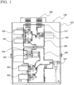
- FIG. 1 is a side sectional view showing a gas insulated switchgear according to embodiment 1.
- a gas insulated switchgear 100 has, inside a housing 101 thereof, a tank 109 for storing a circuit breaker. Inside the tank 109, a circuit breaker 102, a disconnector 103, and a ground switch 104 are stored. The disconnector 103 may be replaced with a ground switch.
- a compartment bushing 105 is provided on the upper side of the tank 109.
- a tank 108 for connecting a bus and storing a disconnector/ground switch is provided on the upper side of the compartment bushing 105.
- a plurality of disconnectors 103 (or ground switches) are provided, and a bushing portion 112 of a bus connection device 110 described later is provided at an upper surface of the tank 108.
- the bushing portion 112 has one end inside the tank 108 and another end outside the tank 108.
- a power cable 107 is provided on the back side of the tank 109.
- the bushing portion 112 is connected to a solid insulation bus 106, at the other end, i.e., outside the tank 108.
- a solid insulation bus 106 When a plurality of panels of gas insulated switchgears 100 are arranged in a row, the gas insulated switchgears 100 are connected to each other via the solid insulation bus 106.
- the solid insulation bus 106 is connected to the gas insulated switchgear 100 via the bus connection device 110.
- FIG. 2 is a side sectional view showing the bus connection device in embodiment 1.
- the bus connection device 110 includes an adapter portion 111 which is a connection part to the solid insulation bus 106, and the bushing portion 112 which is a connection part to the gas insulated switchgear 100.
- the adapter portion 111 has an opening on one side (right side in FIG. 3 ) in the axial direction of the solid insulation bus 106, and the solid insulation bus 106 is inserted into this opening.
- the solid insulation bus 106 has a bus conductor 106a at the center, and has an insulating layer 106b and a ground conductive layer 106c around the bus conductor 106a.
- the adapter portion 111 also has an opening on one side in a direction perpendicular to the axial direction of the solid insulation bus 106 (lower side in FIG. 2 ), and the bushing portion 112 is inserted into this opening.
- the bushing portion 112 extends in the direction perpendicular to the axial direction of the solid insulation bus 106 and has, therein, a conductor portion 112a having an end connected to an internal device of the gas insulated switchgear 100.
- a connection terminal 111b is provided inside the adapter portion 111.
- the connection terminal 111b is connected to the bus conductor 106a of the solid insulation bus 106 and is connected to another end of the conductor portion 112a of the bushing portion 112.
- the bus conductor 106a of the solid insulation bus 106 and the conductor portion 112a of the bushing portion 112 are connected via the connection terminal 111b in the adapter portion 111. Since one end of the conductor portion 112a of the bushing portion 112 is connected to the internal device of the gas insulated switchgear 100, the internal device of the gas insulated switchgear 100 and the solid insulation bus 106 are connected via the bus connection device 110.
- the adapter portion 111 is attached to the other end of the bushing portion 112, and the solid insulation bus 106 is connected to the adapter portion 111.
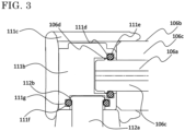
- FIG. 3 is an enlarged sectional view of a part S in FIG. 2 .
- the connection terminal 111b has a recess into which the bus conductor 106a is inserted, at a surface opposed to the solid insulation bus 106.
- a groove 111d is provided on a side surface of this recess (a surface opposed to the outer circumferential surface of the bus conductor 106a).
- a contact member 111e is attached to the groove 111d.
- the contact member 111e has a ring shape surrounding the circumference of the bus conductor 106a, and has high conductivity and high spring property.
- the contact member 111e is made of a copper alloy or the like.
- the contact member 111e contacts with both of the connection terminal 111b and the bus conductor 106a, to ensure conduction between the connection terminal 111b and the bus conductor 106a.
- the connection terminal 111b also has a recess into which the conductor portion 112a is inserted, at a surface opposed to the bushing portion 112.
- a groove 111f is provided on a side surface of this recess (a surface opposed to the outer circumferential surface of the conductor portion 112a).
- a contact member 111g is attached to the groove 111f.
- the contact member 111g has a ring shape surrounding the circumference of the conductor portion 112a, and is made of a copper alloy or the like, as with the contact member 111e.
- the contact member 111g contacts with both of the connection terminal 111b and the conductor portion 112a, to ensure conduction between the connection terminal 111b and the conductor portion 112a.
- the bus conductor 106a has, at an end part thereof, a projection 106d to be engaged with the contact member 111e.
- the conductor portion 112a has, at an end part thereof, a projection 112b to be engaged with the contact member 111g.
- the adapter portion 111 is made of rubber, and when the solid insulation bus 106 and the bushing portion 112 are inserted into the adapter portion 111, insulation performance at insulation interfaces is ensured by the surface pressure of rubber. By the surface pressure of rubber, the adapter portion 111 is subjected to a load in a direction opposite to the insertion direction of the solid insulation bus 106. Considering this, the contact member 111e and the projection 106d in an engaged state have a structure that can withstand the above surface pressure load. For example, the contact area between the contact member 111e and the projection 106d may be made sufficiently large. Thus, the contact member 111e and the projection 106d serve as a come-off stopper structure. The same applies to the contact member 111g and the projection 112b.
- a high-voltage-side conductive layer 111c of the solid insulation bus 106 is provided around the connection terminal 111b. This forms a structure for relaxing an electric field around the connection conductor 111b.
- FIG. 4 is a view of each of the contact member 111e and the contact member 111g shown in FIG. 3 , as seen from the insertion direction of each of the bus conductor 106a and the conductor portion 112a, and illustrates the come-off stopper structure according to embodiment 1.
- the projection 106d (projection 112b) only has to be provided at least at two parts on the bus conductor 106a (conductor portion 112a).
- the projection 106d (projection 112b) may be provided at three or more parts or over the entire range of the outer circumference.
- the gas insulated switchgear is described as an example of an electric device connected to the solid connection bus.
- any electric device such as a switchgear may be applied as long as a plurality of the electric devices are connected via the solid connection bus.
- the contact member is provided also on the bushing portion side.
- the contact member may be provided only on the solid insulation bus side.
- the conductive contact member to contact with the bus conductor of the solid insulation bus is provided at the connection terminal in the adapter portion.
- conduction with the bus conductor is ensured, and therefore it is unnecessary to attach an insulating plug as in the conventional case.
- production of metal chips at the time of attaching the insulating plug does not occur, and thus the insulation performance is not lowered by such chips.
- the conductor portion of the bushing portion and the bus conductor of the solid insulation bus each have a projection at the end part thereof, and the projection and the contact member are engaged with each other. This provides a come-off stopper prevention function so that the solid insulation bus does not readily come off after inserted.
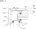
- FIG. 5 is an enlarged sectional view showing a bus connection device in embodiment 2 and corresponds to the part S in FIG. 2 in embodiment 1.
- a bus conductor 206a has, at an end part thereof, a groove 206d to be engaged with the contact member 111e.
- a conductor portion 212a has, at an end part thereof, a groove 212b to be engaged with the contact member 111g.
- the groove 206d is engaged with the contact member 111e by the contact member 111e fitting into the groove 206d, thus serving as a come-off stopper structure for the bus conductor 206a.
- the groove 212b is engaged with the contact member 111g by the contact member 111g fitting into the groove 212b, thus serving as a come-off stopper structure for the conductor portion 212a.
- the amounts of materials needed for manufacturing the conductor portion of the bushing portion and the bus conductor of the solid insulation bus can be reduced. That is, in embodiment 1, since the projections are provided to the bus conductor of the solid insulation bus and the like, thick conductor materials having diameters greater than required conductor diameters need to be used and cut to form the projections. In contrast, in embodiment 2, since the grooves are provided to the bus conductor of the solid insulation bus and the like, it is only necessary to use materials having required conductor diameters and form the grooves. Thus, the diameters of conductor materials needed for the bus conductor and the like can be reduced, whereby the material cost can be reduced.
Landscapes
- Engineering & Computer Science (AREA)
- Power Engineering (AREA)
- Gas-Insulated Switchgears (AREA)
Abstract
Description
- The present disclosure relates to a bus connection device.
- Conventionally, there has been a switchgear or a gas insulated switchgear with a plurality of electric devices such as switches connected via insulation buses (see, for example, Patent Document 1). For connection of switches and the like, a gas bus type in which bus conductors in a bus tank are connected is generally used, but in recent years, a solid insulation bus may also be used. In the case of the gas bus type, it is necessary to connect a bus tank in installation of a gas insulated switchgear, but in the case of using the solid insulation bus, such work is not needed and thus gas processing work on a site in installation of a gas insulated switchgear can be eliminated.
- As described above, there have been increasing cases of using the solid insulation bus for a bus part of the gas insulated switchgear. In the case of using the solid insulation bus, a bushing for connecting a solid insulation bus is provided at each board of the gas insulated switchgear, an adapter is attached to the bushing, and the bushing and the solid insulation bus are connected via the adapter. After the solid insulation bus is connected, an insulating plug is inserted into the adapter and is fixed, whereby the insulation bus connection work is completed.
- Patent Document 1:
Japanese Patent No. 6563160 - However, in the above conventional configuration, the insulation performance of the insulation bus might be lowered when the insulation bus is connected. More specifically, at the time of fixing the insulating plug, a metal fixation screw attached to the bushing is inserted into the adapter and the fixation screw is screwed to an internal thread of the insulating plug, whereby the insulating plug is fixed. When the fixation screw is screwed to the internal thread of the insulating plug, the surface of the fixation screw and the internal thread surface of the insulating plug rub against each other, so that metal chips might be produced from the surface of the fixation screw. The insulation performance of the solid insulation bus might be lowered if the chips enter the insulation interface of the insulating plug.
- The present disclosure has been made to solve the above problem, and an object of the present disclosure is to provide a bus connection device that can prevent the insulation performance of an insulation bus from being lowered when the insulation bus is connected.
- A bus connection device according to the present disclosure is a bus connection device for connecting each of a plurality of electric devices and an insulation bus for connecting the plurality of electric devices, the bus connection device including: an adapter portion into which the insulation bus is inserted, the adapter portion having, therein, a connection terminal having an opening into which a bus conductor of the insulation bus is inserted; a bushing portion having a conductor portion therein and having one end connected to the electric device and another end inserted into the adapter portion, so as to be connected to the insulation bus via the connection terminal; and a conductive contact member provided to the opening of the connection terminal so as to contact with the bus conductor.
- The bus connection device according to the present disclosure can prevent the insulation performance of an insulation bus from being lowered when the insulation bus is connected.
-
- [
FIG. 1] FIG. 1 is a side sectional view showing a gas insulated switchgear according to embodiment 1. - [
FIG. 2] FIG. 2 is a side sectional view showing a bus connection device in embodiment 1. - [
FIG. 3] FIG. 3 is an enlarged sectional view of a part S inFIG. 2 . - [
FIG. 4] FIG. 4 illustrates a come-off stopper structure according to embodiment 1. - [
FIG. 5] FIG. 5 is an enlarged sectional view showing a bus connection device in embodiment 2. - Embodiment 1 will be described with reference to
FIG. 1 to FIG. 4 .FIG. 1 is a side sectional view showing a gas insulated switchgear according to embodiment 1. A gas insulatedswitchgear 100 has, inside ahousing 101 thereof, atank 109 for storing a circuit breaker. Inside thetank 109, acircuit breaker 102, adisconnector 103, and aground switch 104 are stored. Thedisconnector 103 may be replaced with a ground switch. - A
compartment bushing 105 is provided on the upper side of thetank 109. Atank 108 for connecting a bus and storing a disconnector/ground switch is provided on the upper side of the compartment bushing 105. Inside thetank 108, a plurality of disconnectors 103 (or ground switches) are provided, and abushing portion 112 of abus connection device 110 described later is provided at an upper surface of thetank 108. Thebushing portion 112 has one end inside thetank 108 and another end outside thetank 108. Apower cable 107 is provided on the back side of thetank 109. - The
bushing portion 112 is connected to asolid insulation bus 106, at the other end, i.e., outside thetank 108. When a plurality of panels of gas insulatedswitchgears 100 are arranged in a row, the gas insulatedswitchgears 100 are connected to each other via thesolid insulation bus 106. - The
solid insulation bus 106 is connected to the gas insulatedswitchgear 100 via thebus connection device 110.FIG. 2 is a side sectional view showing the bus connection device in embodiment 1. Thebus connection device 110 includes anadapter portion 111 which is a connection part to thesolid insulation bus 106, and thebushing portion 112 which is a connection part to the gas insulatedswitchgear 100. Theadapter portion 111 has an opening on one side (right side inFIG. 3 ) in the axial direction of thesolid insulation bus 106, and thesolid insulation bus 106 is inserted into this opening. Thesolid insulation bus 106 has abus conductor 106a at the center, and has aninsulating layer 106b and a groundconductive layer 106c around thebus conductor 106a. - The
adapter portion 111 also has an opening on one side in a direction perpendicular to the axial direction of the solid insulation bus 106 (lower side inFIG. 2 ), and thebushing portion 112 is inserted into this opening. Thebushing portion 112 extends in the direction perpendicular to the axial direction of thesolid insulation bus 106 and has, therein, aconductor portion 112a having an end connected to an internal device of the gas insulatedswitchgear 100. - A
connection terminal 111b is provided inside theadapter portion 111. Theconnection terminal 111b is connected to thebus conductor 106a of thesolid insulation bus 106 and is connected to another end of theconductor portion 112a of thebushing portion 112. Thus, thebus conductor 106a of thesolid insulation bus 106 and theconductor portion 112a of thebushing portion 112 are connected via theconnection terminal 111b in theadapter portion 111. Since one end of theconductor portion 112a of thebushing portion 112 is connected to the internal device of the gas insulatedswitchgear 100, the internal device of the gas insulatedswitchgear 100 and thesolid insulation bus 106 are connected via thebus connection device 110. At the time of actually connecting thesolid insulation bus 106 to the gas insulatedswitchgear 100, theadapter portion 111 is attached to the other end of thebushing portion 112, and thesolid insulation bus 106 is connected to theadapter portion 111. -
FIG. 3 is an enlarged sectional view of a part S inFIG. 2 . Theconnection terminal 111b has a recess into which thebus conductor 106a is inserted, at a surface opposed to thesolid insulation bus 106. Agroove 111d is provided on a side surface of this recess (a surface opposed to the outer circumferential surface of thebus conductor 106a). Acontact member 111e is attached to thegroove 111d. Thecontact member 111e has a ring shape surrounding the circumference of thebus conductor 106a, and has high conductivity and high spring property. Thecontact member 111e is made of a copper alloy or the like. Thecontact member 111e contacts with both of theconnection terminal 111b and thebus conductor 106a, to ensure conduction between theconnection terminal 111b and thebus conductor 106a. Theconnection terminal 111b also has a recess into which theconductor portion 112a is inserted, at a surface opposed to thebushing portion 112. Agroove 111f is provided on a side surface of this recess (a surface opposed to the outer circumferential surface of theconductor portion 112a). Acontact member 111g is attached to thegroove 111f. Thecontact member 111g has a ring shape surrounding the circumference of theconductor portion 112a, and is made of a copper alloy or the like, as with thecontact member 111e. Thecontact member 111g contacts with both of theconnection terminal 111b and theconductor portion 112a, to ensure conduction between theconnection terminal 111b and theconductor portion 112a. - The
bus conductor 106a has, at an end part thereof, aprojection 106d to be engaged with thecontact member 111e. Theconductor portion 112a has, at an end part thereof, aprojection 112b to be engaged with thecontact member 111g. - The
adapter portion 111 is made of rubber, and when thesolid insulation bus 106 and thebushing portion 112 are inserted into theadapter portion 111, insulation performance at insulation interfaces is ensured by the surface pressure of rubber. By the surface pressure of rubber, theadapter portion 111 is subjected to a load in a direction opposite to the insertion direction of thesolid insulation bus 106. Considering this, thecontact member 111e and theprojection 106d in an engaged state have a structure that can withstand the above surface pressure load. For example, the contact area between thecontact member 111e and theprojection 106d may be made sufficiently large. Thus, thecontact member 111e and theprojection 106d serve as a come-off stopper structure. The same applies to thecontact member 111g and theprojection 112b. - A high-voltage-side
conductive layer 111c of thesolid insulation bus 106 is provided around theconnection terminal 111b. This forms a structure for relaxing an electric field around theconnection conductor 111b. -
FIG. 4 is a view of each of thecontact member 111e and thecontact member 111g shown inFIG. 3 , as seen from the insertion direction of each of thebus conductor 106a and theconductor portion 112a, and illustrates the come-off stopper structure according to embodiment 1. Theprojection 106d (projection 112b) only has to be provided at least at two parts on thebus conductor 106a (conductor portion 112a). Theprojection 106d (projection 112b) may be provided at three or more parts or over the entire range of the outer circumference. - In embodiment 1, the gas insulated switchgear is described as an example of an electric device connected to the solid connection bus. However, without limitation thereto, any electric device such as a switchgear may be applied as long as a plurality of the electric devices are connected via the solid connection bus.
- In embodiment 1, the contact member is provided also on the bushing portion side. However, the contact member may be provided only on the solid insulation bus side.
- According to embodiment 1, it is possible to prevent the insulation performance of the insulation bus from being lowered when the insulation bus is connected. More specifically, the conductive contact member to contact with the bus conductor of the solid insulation bus is provided at the connection terminal in the adapter portion. Thus, conduction with the bus conductor is ensured, and therefore it is unnecessary to attach an insulating plug as in the conventional case. As a result, production of metal chips at the time of attaching the insulating plug does not occur, and thus the insulation performance is not lowered by such chips.
- The conductor portion of the bushing portion and the bus conductor of the solid insulation bus each have a projection at the end part thereof, and the projection and the contact member are engaged with each other. This provides a come-off stopper prevention function so that the solid insulation bus does not readily come off after inserted.
- In addition, since attachment of the insulating plug is not needed, work is completed by merely inserting the solid insulation bus, and thus assemblability is improved.
- Next, embodiment 2 will be described with reference to
FIG. 5 . The same or corresponding parts as those in FIG. - 1 to
FIG. 4 are denoted by the same reference characters, and the description thereof is omitted. In embodiment 2, the basic structure is the same as that inFIG. 1 , but there is a difference in that, in embodiment 1, the projection is used as an engagement portion, whereas in embodiment 2, a groove is used as an engagement portion.FIG. 5 is an enlarged sectional view showing a bus connection device in embodiment 2 and corresponds to the part S inFIG. 2 in embodiment 1. Abus conductor 206a has, at an end part thereof, agroove 206d to be engaged with thecontact member 111e. Aconductor portion 212a has, at an end part thereof, agroove 212b to be engaged with thecontact member 111g. Thegroove 206d is engaged with thecontact member 111e by thecontact member 111e fitting into thegroove 206d, thus serving as a come-off stopper structure for thebus conductor 206a. Thegroove 212b is engaged with thecontact member 111g by thecontact member 111g fitting into thegroove 212b, thus serving as a come-off stopper structure for theconductor portion 212a. - The other matters are the same as in embodiment 1 and therefore the description thereof is omitted.
- According to embodiment 2, the same effects as in embodiment 1 can be provided.
- In addition, since the contact member is fitted into the groove and thus serves as a come-off stopper prevention, the bus conductor of the solid insulation bus and the conductor portion of the bushing portion are more unlikely to come off, as compared to embodiment 1.
- In addition, the amounts of materials needed for manufacturing the conductor portion of the bushing portion and the bus conductor of the solid insulation bus can be reduced. That is, in embodiment 1, since the projections are provided to the bus conductor of the solid insulation bus and the like, thick conductor materials having diameters greater than required conductor diameters need to be used and cut to form the projections. In contrast, in embodiment 2, since the grooves are provided to the bus conductor of the solid insulation bus and the like, it is only necessary to use materials having required conductor diameters and form the grooves. Thus, the diameters of conductor materials needed for the bus conductor and the like can be reduced, whereby the material cost can be reduced.
- Although the disclosure is described above in terms of various exemplary embodiments and implementations, it should be understood that the various features, aspects, and functionality described in one or more of the individual embodiments are not limited in their applicability to the particular embodiment with which they are described, but instead can be applied, alone or in various combinations to one or more of the embodiments of the disclosure.
- It is therefore understood that numerous modifications which have not been exemplified can be devised without departing from the scope of the present disclosure. For example, at least one of the constituent components may be modified, added, or eliminated. At least one of the constituent components mentioned in at least one of the preferred embodiments may be selected and combined with the constituent components mentioned in another preferred embodiment.
-
- 100 gas insulated switchgear
- 106 solid insulation bus
- 106a, 206a bus conductor
- 106d projection
- 110 bus connection device
- 111 adapter portion
- 111b connection terminal
- 111e, 111g contact member
- 112 bushing portion
- 112a, 212a conductor portion
- 112b projection
- 206d groove
- 212b groove
Claims (8)
- A bus connection device for connecting each of a plurality of electric devices and an insulation bus for connecting the plurality of electric devices, the bus connection device comprising:an adapter portion into which the insulation bus is inserted, the adapter portion having, therein, a connection terminal having an opening into which a bus conductor of the insulation bus is inserted;a bushing portion having a conductor portion therein and having one end connected to the electric device and another end inserted into the adapter portion, so as to be connected to the insulation bus via the connection terminal; anda conductive contact member provided to the opening of the connection terminal so as to contact with the bus conductor.
- The bus connection device according to claim 1, wherein
the contact member is engaged with an engagement portion provided at an end part of the bus conductor. - The bus connection device according to claim 1 or 2, wherein
the connection terminal has a second opening into which the conductor portion of the bushing portion is inserted, and a conductive second contact member is provided to the second opening so as to contact with the conductor portion of the bushing portion. - The bus connection device according to claim 3, wherein
the second contact member is engaged with an engagement portion provided at an end part of the conductor portion. - The bus connection device according to claim 2 or 4, wherein
the engagement portion is a projection provided at the end part of the bus conductor. - The bus connection device according to claim 2 or 4, wherein
the engagement portion is a groove which is provided at the end part of the bus conductor and into which the contact member is fitted. - The bus connection device according to claim 4, wherein
the engagement portion is a projection provided at the end part of the conductor portion. - The bus connection device according to claim 4, wherein
the engagement portion is a groove which is provided at the end part of the conductor portion and into which the contact member is fitted.
Applications Claiming Priority (1)
| Application Number | Priority Date | Filing Date | Title |
|---|---|---|---|
| PCT/JP2020/021271 WO2021240759A1 (en) | 2020-05-29 | 2020-05-29 | Bus connection device |
Publications (2)
| Publication Number | Publication Date |
|---|---|
| EP4160835A1 true EP4160835A1 (en) | 2023-04-05 |
| EP4160835A4 EP4160835A4 (en) | 2023-07-19 |
Family
ID=76650092
Family Applications (1)
| Application Number | Title | Priority Date | Filing Date |
|---|---|---|---|
| EP20937578.1A Pending EP4160835A4 (en) | 2020-05-29 | 2020-05-29 | BUS CONNECTION DEVICE |
Country Status (4)
| Country | Link |
|---|---|
| EP (1) | EP4160835A4 (en) |
| JP (1) | JP6899970B1 (en) |
| CN (1) | CN115668674A (en) |
| WO (1) | WO2021240759A1 (en) |
Family Cites Families (11)
| Publication number | Priority date | Publication date | Assignee | Title |
|---|---|---|---|---|
| JPS6280496A (en) | 1985-10-03 | 1987-04-13 | Nippon Foil Mfg Co Ltd | Fin material for heat exchanger |
| JPH0556541A (en) * | 1991-06-28 | 1993-03-05 | Fuji Electric Co Ltd | Insulation busbar connection device |
| DE19528127C2 (en) * | 1995-08-01 | 2000-05-04 | Abb Patent Gmbh | Contacting device for cable connections |
| JPWO2004051816A1 (en) * | 2002-12-04 | 2006-04-06 | 三菱電機株式会社 | Switchgear busbar connection structure |
| JP4690378B2 (en) * | 2007-10-25 | 2011-06-01 | 昭和電線ケーブルシステム株式会社 | connector |
| CN201270398Y (en) * | 2008-06-27 | 2009-07-08 | 上海市电力公司 | Dual row bus bar connecting device |
| CN102318154A (en) * | 2009-02-13 | 2012-01-11 | 三菱电机株式会社 | Contact device |
| JP5761108B2 (en) * | 2012-04-06 | 2015-08-12 | 日立金属株式会社 | Solid insulation bus termination connection |
| EP3073592B1 (en) * | 2013-11-19 | 2022-03-16 | Mitsubishi Electric Corporation | Bus connection device and switchgear using same |
| EP3905460A4 (en) * | 2018-12-26 | 2021-12-08 | Mitsubishi Electric Corporation | BUSBAR CONNECTING DEVICE |
| CN111009789A (en) * | 2019-12-25 | 2020-04-14 | 珠海沃顿电气有限公司 | Bus connecting device and switch cabinet with same |
-
2020
- 2020-05-29 JP JP2020552433A patent/JP6899970B1/en active Active
- 2020-05-29 WO PCT/JP2020/021271 patent/WO2021240759A1/en not_active Ceased
- 2020-05-29 EP EP20937578.1A patent/EP4160835A4/en active Pending
- 2020-05-29 CN CN202080101096.4A patent/CN115668674A/en active Pending
Also Published As
| Publication number | Publication date |
|---|---|
| JP6899970B1 (en) | 2021-07-07 |
| JPWO2021240759A1 (en) | 2021-12-02 |
| CN115668674A (en) | 2023-01-31 |
| EP4160835A4 (en) | 2023-07-19 |
| WO2021240759A1 (en) | 2021-12-02 |
Similar Documents
| Publication | Publication Date | Title |
|---|---|---|
| US20120231676A1 (en) | Casing for an electrical connector | |
| US9112322B2 (en) | Electrical connector with multiple interfaces | |
| CN101490780B (en) | Switches for power supply and distribution switchgear | |
| US7173809B2 (en) | Multiphase busbar system | |
| EP0087267B1 (en) | An electrical high-voltage connector and connection assembly | |
| EP3062403A1 (en) | Gas-insulated switchgear | |
| EP4131680A1 (en) | Gas-insulated switchgear | |
| JP6563160B1 (en) | Busbar connection device | |
| EP4160835A1 (en) | Bus connection device | |
| US7534151B1 (en) | Electrical connection terminal | |
| EP4421999A1 (en) | Touch protection cover, connection member, module connector and battery system | |
| US5872346A (en) | Metal-cladded electrical high-voltage switching installation with a power switch | |
| RU2430442C2 (en) | Connector to be mounted on casing with fuses | |
| US8193467B2 (en) | Insulator with disc-shaped carrier element | |
| US20150380865A1 (en) | Securing device for gis | |
| EP4318835A1 (en) | Solid insulated bus and gas-insulated switchgear provided therewith | |
| KR200235038Y1 (en) | Earth device for power cable | |
| JP4540910B2 (en) | Electrical connection device for power circuit breaker | |
| CN213879062U (en) | Gas-insulated metal-enclosed switch modules and their terminal closure assemblies | |
| KR102823190B1 (en) | Safety joint for detecting fault position including insulation cover | |
| CN112701005B (en) | Combined electric connection and isolating grounding switch using the same | |
| HK40050175B (en) | Busbar connecting device | |
| HK40050175A (en) | Busbar connecting device | |
| JP2005353540A (en) | Connection terminal structure of shielded cable and electrical connection structure thereof | |
| TW202547079A (en) | Deadbreak grounding device |
Legal Events
| Date | Code | Title | Description |
|---|---|---|---|
| STAA | Information on the status of an ep patent application or granted ep patent |
Free format text: STATUS: THE INTERNATIONAL PUBLICATION HAS BEEN MADE |
|
| PUAI | Public reference made under article 153(3) epc to a published international application that has entered the european phase |
Free format text: ORIGINAL CODE: 0009012 |
|
| STAA | Information on the status of an ep patent application or granted ep patent |
Free format text: STATUS: REQUEST FOR EXAMINATION WAS MADE |
|
| 17P | Request for examination filed |
Effective date: 20220908 |
|
| AK | Designated contracting states |
Kind code of ref document: A1 Designated state(s): AL AT BE BG CH CY CZ DE DK EE ES FI FR GB GR HR HU IE IS IT LI LT LU LV MC MK MT NL NO PL PT RO RS SE SI SK SM TR |
|
| A4 | Supplementary search report drawn up and despatched |
Effective date: 20230619 |
|
| RIC1 | Information provided on ipc code assigned before grant |
Ipc: H02B 13/00 20060101ALI20230614BHEP Ipc: H01R 31/06 20060101ALI20230614BHEP Ipc: H01R 13/627 20060101ALI20230614BHEP Ipc: H01R 13/53 20060101ALI20230614BHEP Ipc: H01R 13/20 20060101ALI20230614BHEP Ipc: H01R 13/187 20060101ALI20230614BHEP Ipc: H02B 1/20 20060101AFI20230614BHEP |
|
| DAV | Request for validation of the european patent (deleted) | ||
| DAX | Request for extension of the european patent (deleted) | ||
| STAA | Information on the status of an ep patent application or granted ep patent |
Free format text: STATUS: EXAMINATION IS IN PROGRESS |
|
| 17Q | First examination report despatched |
Effective date: 20250612 |