EP4160809A1 - Battery assembly and medical capsule - Google Patents
Battery assembly and medical capsule Download PDFInfo
- Publication number
- EP4160809A1 EP4160809A1 EP21818676.5A EP21818676A EP4160809A1 EP 4160809 A1 EP4160809 A1 EP 4160809A1 EP 21818676 A EP21818676 A EP 21818676A EP 4160809 A1 EP4160809 A1 EP 4160809A1
- Authority
- EP
- European Patent Office
- Prior art keywords
- connector
- battery
- negative electrode
- output portion
- positive electrode
- Prior art date
- Legal status (The legal status is an assumption and is not a legal conclusion. Google has not performed a legal analysis and makes no representation as to the accuracy of the status listed.)
- Withdrawn
Links
Images



Classifications
-
- H—ELECTRICITY
- H01—ELECTRIC ELEMENTS
- H01M—PROCESSES OR MEANS, e.g. BATTERIES, FOR THE DIRECT CONVERSION OF CHEMICAL ENERGY INTO ELECTRICAL ENERGY
- H01M50/00—Constructional details or processes of manufacture of the non-active parts of electrochemical cells other than fuel cells, e.g. hybrid cells
- H01M50/50—Current conducting connections for cells or batteries
- H01M50/502—Interconnectors for connecting terminals of adjacent batteries; Interconnectors for connecting cells outside a battery casing
-
- A—HUMAN NECESSITIES
- A61—MEDICAL OR VETERINARY SCIENCE; HYGIENE
- A61B—DIAGNOSIS; SURGERY; IDENTIFICATION
- A61B1/00—Instruments for performing medical examinations of the interior of cavities or tubes of the body by visual or photographical inspection, e.g. endoscopes; Illuminating arrangements therefor
- A61B1/04—Instruments for performing medical examinations of the interior of cavities or tubes of the body by visual or photographical inspection, e.g. endoscopes; Illuminating arrangements therefor combined with photographic or television appliances
- A61B1/041—Capsule endoscopes for imaging
-
- A—HUMAN NECESSITIES
- A61—MEDICAL OR VETERINARY SCIENCE; HYGIENE
- A61B—DIAGNOSIS; SURGERY; IDENTIFICATION
- A61B1/00—Instruments for performing medical examinations of the interior of cavities or tubes of the body by visual or photographical inspection, e.g. endoscopes; Illuminating arrangements therefor
- A61B1/00002—Operational features of endoscopes
- A61B1/00011—Operational features of endoscopes characterised by signal transmission
- A61B1/00016—Operational features of endoscopes characterised by signal transmission using wireless means
-
- A—HUMAN NECESSITIES
- A61—MEDICAL OR VETERINARY SCIENCE; HYGIENE
- A61B—DIAGNOSIS; SURGERY; IDENTIFICATION
- A61B1/00—Instruments for performing medical examinations of the interior of cavities or tubes of the body by visual or photographical inspection, e.g. endoscopes; Illuminating arrangements therefor
- A61B1/00002—Operational features of endoscopes
- A61B1/00025—Operational features of endoscopes characterised by power management
- A61B1/00027—Operational features of endoscopes characterised by power management characterised by power supply
- A61B1/00032—Operational features of endoscopes characterised by power management characterised by power supply internally powered
-
- A—HUMAN NECESSITIES
- A61—MEDICAL OR VETERINARY SCIENCE; HYGIENE
- A61B—DIAGNOSIS; SURGERY; IDENTIFICATION
- A61B1/00—Instruments for performing medical examinations of the interior of cavities or tubes of the body by visual or photographical inspection, e.g. endoscopes; Illuminating arrangements therefor
- A61B1/00064—Constructional details of the endoscope body
- A61B1/0011—Manufacturing of endoscope parts
-
- H—ELECTRICITY
- H01—ELECTRIC ELEMENTS
- H01M—PROCESSES OR MEANS, e.g. BATTERIES, FOR THE DIRECT CONVERSION OF CHEMICAL ENERGY INTO ELECTRICAL ENERGY
- H01M50/00—Constructional details or processes of manufacture of the non-active parts of electrochemical cells other than fuel cells, e.g. hybrid cells
- H01M50/20—Mountings; Secondary casings or frames; Racks, modules or packs; Suspension devices; Shock absorbers; Transport or carrying devices; Holders
-
- H—ELECTRICITY
- H01—ELECTRIC ELEMENTS
- H01M—PROCESSES OR MEANS, e.g. BATTERIES, FOR THE DIRECT CONVERSION OF CHEMICAL ENERGY INTO ELECTRICAL ENERGY
- H01M50/00—Constructional details or processes of manufacture of the non-active parts of electrochemical cells other than fuel cells, e.g. hybrid cells
- H01M50/20—Mountings; Secondary casings or frames; Racks, modules or packs; Suspension devices; Shock absorbers; Transport or carrying devices; Holders
- H01M50/204—Racks, modules or packs for multiple batteries or multiple cells
- H01M50/207—Racks, modules or packs for multiple batteries or multiple cells characterised by their shape
- H01M50/209—Racks, modules or packs for multiple batteries or multiple cells characterised by their shape adapted for prismatic or rectangular cells
-
- H—ELECTRICITY
- H01—ELECTRIC ELEMENTS
- H01M—PROCESSES OR MEANS, e.g. BATTERIES, FOR THE DIRECT CONVERSION OF CHEMICAL ENERGY INTO ELECTRICAL ENERGY
- H01M50/00—Constructional details or processes of manufacture of the non-active parts of electrochemical cells other than fuel cells, e.g. hybrid cells
- H01M50/20—Mountings; Secondary casings or frames; Racks, modules or packs; Suspension devices; Shock absorbers; Transport or carrying devices; Holders
- H01M50/204—Racks, modules or packs for multiple batteries or multiple cells
- H01M50/207—Racks, modules or packs for multiple batteries or multiple cells characterised by their shape
- H01M50/213—Racks, modules or packs for multiple batteries or multiple cells characterised by their shape adapted for cells having curved cross-section, e.g. round or elliptic
-
- H—ELECTRICITY
- H01—ELECTRIC ELEMENTS
- H01M—PROCESSES OR MEANS, e.g. BATTERIES, FOR THE DIRECT CONVERSION OF CHEMICAL ENERGY INTO ELECTRICAL ENERGY
- H01M50/00—Constructional details or processes of manufacture of the non-active parts of electrochemical cells other than fuel cells, e.g. hybrid cells
- H01M50/20—Mountings; Secondary casings or frames; Racks, modules or packs; Suspension devices; Shock absorbers; Transport or carrying devices; Holders
- H01M50/233—Mountings; Secondary casings or frames; Racks, modules or packs; Suspension devices; Shock absorbers; Transport or carrying devices; Holders characterised by physical properties of casings or racks, e.g. dimensions
- H01M50/24—Mountings; Secondary casings or frames; Racks, modules or packs; Suspension devices; Shock absorbers; Transport or carrying devices; Holders characterised by physical properties of casings or racks, e.g. dimensions adapted for protecting batteries from their environment, e.g. from corrosion
-
- H—ELECTRICITY
- H01—ELECTRIC ELEMENTS
- H01M—PROCESSES OR MEANS, e.g. BATTERIES, FOR THE DIRECT CONVERSION OF CHEMICAL ENERGY INTO ELECTRICAL ENERGY
- H01M50/00—Constructional details or processes of manufacture of the non-active parts of electrochemical cells other than fuel cells, e.g. hybrid cells
- H01M50/20—Mountings; Secondary casings or frames; Racks, modules or packs; Suspension devices; Shock absorbers; Transport or carrying devices; Holders
- H01M50/247—Mountings; Secondary casings or frames; Racks, modules or packs; Suspension devices; Shock absorbers; Transport or carrying devices; Holders specially adapted for portable devices, e.g. mobile phones, computers, hand tools or pacemakers
-
- H—ELECTRICITY
- H01—ELECTRIC ELEMENTS
- H01M—PROCESSES OR MEANS, e.g. BATTERIES, FOR THE DIRECT CONVERSION OF CHEMICAL ENERGY INTO ELECTRICAL ENERGY
- H01M50/00—Constructional details or processes of manufacture of the non-active parts of electrochemical cells other than fuel cells, e.g. hybrid cells
- H01M50/20—Mountings; Secondary casings or frames; Racks, modules or packs; Suspension devices; Shock absorbers; Transport or carrying devices; Holders
- H01M50/296—Mountings; Secondary casings or frames; Racks, modules or packs; Suspension devices; Shock absorbers; Transport or carrying devices; Holders characterised by terminals of battery packs
-
- H—ELECTRICITY
- H01—ELECTRIC ELEMENTS
- H01M—PROCESSES OR MEANS, e.g. BATTERIES, FOR THE DIRECT CONVERSION OF CHEMICAL ENERGY INTO ELECTRICAL ENERGY
- H01M50/00—Constructional details or processes of manufacture of the non-active parts of electrochemical cells other than fuel cells, e.g. hybrid cells
- H01M50/50—Current conducting connections for cells or batteries
-
- H—ELECTRICITY
- H01—ELECTRIC ELEMENTS
- H01M—PROCESSES OR MEANS, e.g. BATTERIES, FOR THE DIRECT CONVERSION OF CHEMICAL ENERGY INTO ELECTRICAL ENERGY
- H01M50/00—Constructional details or processes of manufacture of the non-active parts of electrochemical cells other than fuel cells, e.g. hybrid cells
- H01M50/50—Current conducting connections for cells or batteries
- H01M50/502—Interconnectors for connecting terminals of adjacent batteries; Interconnectors for connecting cells outside a battery casing
- H01M50/503—Interconnectors for connecting terminals of adjacent batteries; Interconnectors for connecting cells outside a battery casing characterised by the shape of the interconnectors
-
- H—ELECTRICITY
- H01—ELECTRIC ELEMENTS
- H01M—PROCESSES OR MEANS, e.g. BATTERIES, FOR THE DIRECT CONVERSION OF CHEMICAL ENERGY INTO ELECTRICAL ENERGY
- H01M50/00—Constructional details or processes of manufacture of the non-active parts of electrochemical cells other than fuel cells, e.g. hybrid cells
- H01M50/50—Current conducting connections for cells or batteries
- H01M50/502—Interconnectors for connecting terminals of adjacent batteries; Interconnectors for connecting cells outside a battery casing
- H01M50/509—Interconnectors for connecting terminals of adjacent batteries; Interconnectors for connecting cells outside a battery casing characterised by the type of connection, e.g. mixed connections
-
- H—ELECTRICITY
- H01—ELECTRIC ELEMENTS
- H01M—PROCESSES OR MEANS, e.g. BATTERIES, FOR THE DIRECT CONVERSION OF CHEMICAL ENERGY INTO ELECTRICAL ENERGY
- H01M50/00—Constructional details or processes of manufacture of the non-active parts of electrochemical cells other than fuel cells, e.g. hybrid cells
- H01M50/50—Current conducting connections for cells or batteries
- H01M50/502—Interconnectors for connecting terminals of adjacent batteries; Interconnectors for connecting cells outside a battery casing
- H01M50/509—Interconnectors for connecting terminals of adjacent batteries; Interconnectors for connecting cells outside a battery casing characterised by the type of connection, e.g. mixed connections
- H01M50/51—Connection only in series
-
- H—ELECTRICITY
- H01—ELECTRIC ELEMENTS
- H01M—PROCESSES OR MEANS, e.g. BATTERIES, FOR THE DIRECT CONVERSION OF CHEMICAL ENERGY INTO ELECTRICAL ENERGY
- H01M50/00—Constructional details or processes of manufacture of the non-active parts of electrochemical cells other than fuel cells, e.g. hybrid cells
- H01M50/50—Current conducting connections for cells or batteries
- H01M50/502—Interconnectors for connecting terminals of adjacent batteries; Interconnectors for connecting cells outside a battery casing
- H01M50/509—Interconnectors for connecting terminals of adjacent batteries; Interconnectors for connecting cells outside a battery casing characterised by the type of connection, e.g. mixed connections
- H01M50/512—Connection only in parallel
-
- H—ELECTRICITY
- H01—ELECTRIC ELEMENTS
- H01M—PROCESSES OR MEANS, e.g. BATTERIES, FOR THE DIRECT CONVERSION OF CHEMICAL ENERGY INTO ELECTRICAL ENERGY
- H01M50/00—Constructional details or processes of manufacture of the non-active parts of electrochemical cells other than fuel cells, e.g. hybrid cells
- H01M50/50—Current conducting connections for cells or batteries
- H01M50/502—Interconnectors for connecting terminals of adjacent batteries; Interconnectors for connecting cells outside a battery casing
- H01M50/514—Methods for interconnecting adjacent batteries or cells
- H01M50/516—Methods for interconnecting adjacent batteries or cells by welding, soldering or brazing
-
- H—ELECTRICITY
- H01—ELECTRIC ELEMENTS
- H01M—PROCESSES OR MEANS, e.g. BATTERIES, FOR THE DIRECT CONVERSION OF CHEMICAL ENERGY INTO ELECTRICAL ENERGY
- H01M50/00—Constructional details or processes of manufacture of the non-active parts of electrochemical cells other than fuel cells, e.g. hybrid cells
- H01M50/50—Current conducting connections for cells or batteries
- H01M50/502—Interconnectors for connecting terminals of adjacent batteries; Interconnectors for connecting cells outside a battery casing
- H01M50/521—Interconnectors for connecting terminals of adjacent batteries; Interconnectors for connecting cells outside a battery casing characterised by the material
- H01M50/522—Inorganic material
-
- A—HUMAN NECESSITIES
- A61—MEDICAL OR VETERINARY SCIENCE; HYGIENE
- A61H—PHYSICAL THERAPY APPARATUS, e.g. DEVICES FOR LOCATING OR STIMULATING REFLEX POINTS IN THE BODY; ARTIFICIAL RESPIRATION; MASSAGE; BATHING DEVICES FOR SPECIAL THERAPEUTIC OR HYGIENIC PURPOSES OR SPECIFIC PARTS OF THE BODY
- A61H21/00—Massage devices for cavities of the body, e.g. nose, ears and anus ; Vibration or percussion related aspects A61H23/00
-
- A—HUMAN NECESSITIES
- A61—MEDICAL OR VETERINARY SCIENCE; HYGIENE
- A61H—PHYSICAL THERAPY APPARATUS, e.g. DEVICES FOR LOCATING OR STIMULATING REFLEX POINTS IN THE BODY; ARTIFICIAL RESPIRATION; MASSAGE; BATHING DEVICES FOR SPECIAL THERAPEUTIC OR HYGIENIC PURPOSES OR SPECIFIC PARTS OF THE BODY
- A61H23/00—Percussion or vibration massage, e.g. using supersonic vibration; Suction-vibration massage; Massage with moving diaphragms
- A61H23/02—Percussion or vibration massage, e.g. using supersonic vibration; Suction-vibration massage; Massage with moving diaphragms with electric or magnetic drive
-
- H—ELECTRICITY
- H01—ELECTRIC ELEMENTS
- H01M—PROCESSES OR MEANS, e.g. BATTERIES, FOR THE DIRECT CONVERSION OF CHEMICAL ENERGY INTO ELECTRICAL ENERGY
- H01M2220/00—Batteries for particular applications
- H01M2220/30—Batteries in portable systems, e.g. mobile phone, laptop
-
- Y—GENERAL TAGGING OF NEW TECHNOLOGICAL DEVELOPMENTS; GENERAL TAGGING OF CROSS-SECTIONAL TECHNOLOGIES SPANNING OVER SEVERAL SECTIONS OF THE IPC; TECHNICAL SUBJECTS COVERED BY FORMER USPC CROSS-REFERENCE ART COLLECTIONS [XRACs] AND DIGESTS
- Y02—TECHNOLOGIES OR APPLICATIONS FOR MITIGATION OR ADAPTATION AGAINST CLIMATE CHANGE
- Y02E—REDUCTION OF GREENHOUSE GAS [GHG] EMISSIONS, RELATED TO ENERGY GENERATION, TRANSMISSION OR DISTRIBUTION
- Y02E60/00—Enabling technologies; Technologies with a potential or indirect contribution to GHG emissions mitigation
- Y02E60/10—Energy storage using batteries
Definitions
- the present invention relates to the field of medical device, and more particularly to a battery assembly and a medical capsule capable of outputting various voltages.
- a battery unit supplies power to other internal components. So, the safety, stability and other factors of the battery unit need to be comprehensively evaluated. At present, there are few large-capacity single-cell batteries that can meet the requirements of medical capsule devices, and basically only lithium batteries can be selected. However, the safety of lithium batteries in wide application needs to be verified.
- An object of the present invention is to provide a battery assembly and a medical capsule capable of outputting various voltages.
- the present invention uses the following technical solution:
- the battery is a silver oxide battery.
- the connector is a nickel-plated SPCC steel sheet, a nickel sheet or a copper sheet.
- each of the positive electrode connector, the negative electrode connector and the intermediate connector comprises a welding portion welded to an electrode of the battery and an output portion connected to the welding portion.
- the output portion of the positive electrode connector and the output portion of the negative electrode connector extend towards a side of the positive electrode of the battery pack or a side of the negative electrode of the battery pack, and the output portion of the intermediate connector extends towards another side of the battery pack.
- the battery assembly further comprises an insulation assembly arranged between adjacent batteries or between the connector and the batteries.
- the insulation assembly comprises an insulation gasket disposed around the negative electrode of the battery.
- each of the positive electrode connector, the negative electrode connector and the intermediate connector comprises a welding portion welded to an electrode of the battery and an output portion connected to the welding portion.
- the output portion of the positive electrode connector and the output portion of the negative electrode connector extend towards a side of the positive electrode of the battery pack, and the output portion of the intermediate connector extends towards a side of the negative electrode of the battery pack.
- the insulation assembly further comprises a first insulation sheet disposed on the side of the output portion of the negative electrode connector facing the battery.
- an insulation sheet is or is not disposed on the side of the output portion of the intermediate connector facing the battery.
- an insulation sheet is disposed on the side of the output portion of the intermediate connector facing the batteries.
- each of the positive electrode connector, the negative electrode connector, and the intermediate connector comprises a welding portion welded to an electrode of the battery and an output portion connected to the welding portion; wherein the output portion of the positive electrode connector and the output portion of the negative electrode connector both extend towards the side of the negative electrode of the battery pack, and the output portion of the intermediate connector extends towards the side of the positive electrode of the battery pack; and wherein the insulation assembly also comprises a second insulation sheet and a third insulation sheet, wherein the second insulation sheet is disposed on the side of the output portion of the positive electrode connector facing the battery, and the third insulation sheet is disposed on the side of the output portion of the intermediate connector facing the battery.
- a medical capsule comprises the battery assembly.
- the medical capsule is a vibrating capsule, and further comprises an enclosure, a vibration source and a control unit, wherein the vibration source and the control unit are housed in the enclosure, the control unit comprises a PCB, the positive electrode connector and the negative electrode connector are both electrically connected to the PCB, and the vibration source is electrically connected to both the PCB and the intermediate connector.
- the battery is a silver oxide battery.
- the connector is a nickel-plated SPCC steel sheet, a nickel sheet or a copper sheet.
- each of the positive electrode connector, the negative electrode connector and the intermediate connector comprises a welding portion welded to an electrode of the battery and an output portion connected to the welding portion.
- the output portion of the positive electrode connector and the output portion of the negative electrode connector extend towards a side of the positive electrode of the battery pack or a side of the negative electrode of the battery pack, and the output portion of the intermediate connector extends towards another side of the battery pack.
- the battery assembly further comprises an insulation assembly arranged between adjacent batteries or between the connector and the batteries.
- the insulation assembly comprises an insulation gasket disposed around the negative electrode of the battery.
- each of the positive electrode connector, the negative electrode connector and the intermediate connector comprises a welding portion welded to an electrode of the battery and an output portion connected to the welding portion; wherein the output portion of the positive electrode connector and the output portion of the negative electrode connector extend towards a side of the positive electrode of the battery pack, and the output portion of the intermediate connector extends towards a side of the negative electrode of the battery pack; wherein the insulation assembly further comprises a first insulation sheet (32) disposed on the side of the output portion of the negative electrode connector facing the battery; wherein an insulation sheet is or is not disposed on the side of the output portion of the intermediate connector facing the battery when one battery is arranged between the welding portion of the intermediate connector and the negative electrode of the battery pack; and wherein an insulation sheet is disposed on the side of the output portion of the intermediate connector facing the batteries when at least two batteries are arranged between the welding portion of the intermediate connector and the negative electrode of the battery pack.
- each of the positive electrode connector, the negative electrode connector, and the intermediate connector comprises a welding portion welded to an electrode of the battery and an output portion connected to the welding portion; wherein the output portion of the positive electrode connector and the output portion of the negative electrode connector both extend towards the side of the negative electrode of the battery pack, and the output portion of the intermediate connector extends towards the side of the positive electrode of the battery pack; and wherein the insulation assembly also comprises a second insulation sheet and a third insulation sheet, wherein the second insulation sheet is disposed on the side of the output portion of the positive electrode connector facing the battery, and the third insulation sheet is disposed on the side of the output portion of the intermediate connector facing the battery.
- the battery assembly can output a total voltage of the battery pack through the positive electrode connector and the negative electrode connector, and can also output a voltage of part of the battery pack through the cooperation of one of the positive electrode or the negative electrode with the intermediate connector, so that different voltages can be provided to different electrical components and also different voltages can be provided to the same electrical component as required.
- 100-battery assembly 100-battery assembly; 1-battery pack, 11-battery, 111-positive electrode, 112-negative electrode, 2-connector, 21-positive electrode connector, 22-negative electrode connector, 23-intermediate connector, 24-welding portion, 25-output portion, 251-output portion of positive electrode connector, 252-output portion of negative electrode connector, 253-output portion of intermediate connector, 3-insulation assembly, 31-insulation gasket, 32-first insulation sheet, 200-medical capsule, 4-enclosure, 5-vibration source, 6-control unit, 61-PCB, 62-reed switch, 7-fixing structure.
- a battery assembly 100 comprises a battery pack 1 and a plurality of connectors 2 electrically connected to the battery pack 1.
- the electrical connection may be realized by welding or conductive adhesive.
- the battery pack 1 comprises at least two batteries 11 connected in series.
- at least two batteries 11 are arranged in a stack, and the number of the batteries 11 can be adjusted according to a required output voltage.
- the battery 11 is a button type silver oxide battery, which is small in size, safe and stable enough to meet safety requirements of a medical capsule 200.
- the plurality of connectors 2 comprises a positive electrode connector 21 electrically connected to a positive electrode 111 of the battery pack 1, a negative electrode connector 22 electrically connected to the negative electrode 112 of the battery pack 1, and an intermediate connector 23 electrically connected to a positive electrode 111 of one of any two adjacent batteries 11 and a negative electrode 112 of the other of any two adjacent batteries 11. Therefore, the total voltage of the battery pack 1 can be output through the positive electrode connector 21 and the negative electrode connector 22, and the voltage of part of the battery pack 1 can be output through the cooperation of one of the positive electrode or the negative electrode with the intermediate connector 23, so as to supply power to different electrical components, or provide different voltages to the same electrical component as required.
- the voltage of part of the battery pack 1 can be output means that the battery pack 1 comprises at least two batteries 11 connected in series, and the voltages of N batteries 11 are output through the cooperation of one of the positive electrode or the negative electrode with the intermediate connector 23, wherein N is an integer not greater than the total number of the batteries 11 contained in the battery pack 11.
- the battery pack 1 comprises two batteries 11 connected in series, and the voltage of one battery 11 can be output.
- the number of the batteries 11 connected in series between the intermediate connector 23 and the positive electrode connector 21 and the number of the batteries 11 connected in series between the intermediate connector 23 and the negative electrode connector 22 can be adjusted according to a required output voltage. For example, one battery 11 is connected in series between the intermediate connector 23 and the positive electrode connector 21, or one battery 11 is connected in series between the intermediate connector 23 and the negative electrode connector 22, so that the voltage of a single battery 11 can be output.
- the connector 2 further comprises a welding portion 24 welded to the battery 11, and an output portion 25 connected to the welding portion 24.
- the welding portion 24 and the output portion 25 are integrally formed, and the output portion 25 can be bent into a desired shape to facilitate installation in the medical capsule 200.
- the connector 2 comprises the positive electrode connector 21, the negative electrode connector 22 and the intermediate connector 23.
- the structures of the positive electrode connector 21 and the negative electrode connector 22 are similar, and the welding portion 24 thereof is circular, which is convenient for multiple-point welding with the battery pack 1 and improves the welding stability.
- the welding portion 24 comprises a plurality of welding points, for example, the welding portion 24 comprises at least four welding points, which can be welded by soldering, highpressure spot welding or laser spot welding to improve the stability of power supply.
- the output portions 251 and 252 are strip-shaped for easy bending.
- the connector 2 is connected to the electrode of the battery 11 by a spot welding process, preferably by the laser spot welding, which features high consistency and high degree of automation.
- the connector 2 is welded to a printed circuit board (PCB) or a load electrical element by soldering, so as to maintain the stability of welding.
- PCB printed circuit board
- the intermediate connector 23 is strip-shaped, and the welding portion thereof is stacked between two adjacent batteries 11 after being welded to the two adjacent batteries 11.
- the connector 2 is a nickel-plated SPCC (Cold Rolled Steel, generally using cold-rolled carbon steel sheet and steel strip) steel sheet, a nickel sheet or a copper sheet, which can be welded to the electrode of the battery 11, the PCB and the load electrical element.
- a pure nickel sheet is selected to effectively avoid cold solder joint.
- the pure nickel sheet is formed from pure nickel commonly mentioned in the industry, which is allowed to contain trace impurities that cannot be eliminated in the purification process, not referring to 100% pure nickel.
- the output portion of the positive electrode connector 251 and the output portion of the negative electrode connector 252 extend towards a side of the positive electrode 111 of the battery pack 1 or a side of the negative electrode 112 of the battery pack 1, so as to be soldered to a same PCB.
- the output portion of the intermediate connector 253 extends towards another side of the battery pack 1.
- the output portion of the intermediate connector 253 is connected to a load electrical element, so as to cooperate with the PCB to output part of voltage of the whole battery pack 1 to the load electrical element.
- both the output portion of the positive electrode connector 251 and the output portion of the negative electrode connector 252 extend towards the side of the positive electrode 111 of the battery pack 1, so as to be soldered to the PCB.
- the output portion of the intermediate connector 253 extends towards the side of the negative electrode 112 of the battery pack 1.
- the battery assembly 100 further comprises an insulation assembly 3, and those skilled in the art can understand that the insulation assembly 3 is disposed between two components requiring insulation to avoid short circuit.
- the insulation assembly 3 is disposed between adjacent batteries 11, between the connector 2 and the battery 11, between the battery pack 100 and an adjacent PCB, or between the battery assembly 100 and other adjacent electrical components.
- the insulation assembly 3 comprises an annular insulation gasket 31 located around the negative electrode 112 of the battery 11, which is adhered to the negative electrode 112 of the battery 11 and just covers the positive electrode part around the negative electrode 112 of the battery 11, so as to avoid short circuit between the positive electrode area and the negative electrode area of the battery 11 caused by devices or other electrical contacts.
- the negative electrode 112 may be isolated from the positive electrode portion around the negative electrode 112, or the connector 2 connected to the negative electrode 112 may be isolated from the positive electrode portion around the negative electrode 112.
- the insulation gasket 31 is a film made of polyethylene terephthalate (PET), polyvinyl chloride (PVC), polypropylene (PP), or polyamide (PA) with backing.
- the thickness of the insulation gasket 31 is 0.01 mm to 0.5 mm, preferably 0.05 mm to 0.15 mm, which can not only meet the requirements of high conformance rate, but also achieve good insulation characteristics.
- the output portion of the positive electrode connector 251 and the output portion of the negative electrode connector 252 extend towards the side of the positive electrode 111 of the battery pack 1, and the output portion of the intermediate connector 253 extends towards the side of the negative electrode 112 of the battery pack 1. Insulation is required between the negative electrode connector 22 and the side wall of the battery pack 1.
- the insulation assembly 3 further comprises a first insulation sheet 32 disposed on a side of the output portion of the negative electrode connector 252 facing the battery 11, so as to insulate the negative electrode connector 22 from the side wall of the battery pack 1.
- the first insulation sheet 32 is bent and extends to a side of the positive electrode connector 21 away from the battery pack 1, so as to insulate and separate the whole battery assembly 100 from the PCB.
- the output portion of the intermediate connector 253 does not need to be insulated from the side wall of the battery 11. Therefore, the side of the output portion of the intermediate connector 253 facing the battery 11 may or may not be provided with an insulation sheet. If there are at least two batteries 11 between the welding portion of the intermediate connector 23 and the negative electrode 112 of the battery pack 1, an insulation sheet should be disposed on the side of the output portion of the intermediate connector 253 facing the batteries 11 to avoid short circuit.
- each of the output portion of the positive electrode connector 251 and the output portion of the negative electrode connector 252 extends towards the side of the negative electrode 112 of the battery pack 1
- the output portion of the intermediate connector 253 extends towards the side of the positive electrode 111 of the battery pack 1.
- the insulation assembly 3 further comprises a second insulation sheet disposed on a side of the output portion of the positive electrode connector 251 facing the battery 11, and a third insulation sheet disposed on a side of the output portion of the intermediate connector 253 facing the battery 11.
- the battery assembly 100 of the present invention may be used with a variety of medical capsules 200 including, but not limited to, vibrating capsules, endoscopic capsules, etc.
- the medical capsule 200 is a vibrating capsule, comprising an enclosure 4, a vibration source 5 housed in the enclosure 4, the battery assembly 100, and a control unit 6.
- the vibration source 5, the battery assembly 100 and the control unit 6 are fixed in the enclosure 4 by a fixing structure 7.
- the enclosure 4 and the vibration source 5 are any one of the prior art, and the battery assembly 100 is any one of the above.
- the control unit 6 comprises a PCB 61 and a reed switch 62 communicatively connected to the PCB 61.
- the positive electrode connector 21 and the negative electrode connector 22 are electrically connected to the PCB 61.
- the vibration source 5 is electrically connected to both the PCB 61 and the intermediate connector 23, so that different voltages can be output within the allowable voltage range of the vibration source 5.
- the battery assembly 100 of the present invention can output the total voltage of the battery pack 1 through the positive electrode connector 21 and the negative electrode connector 22, and can also output the voltage of part of the battery pack 1 through the cooperation of one of the positive electrode or the negative electrode and the intermediate connector 23, to power different electrical components or to supply different voltages to the same electrical component as required.
Landscapes
- Health & Medical Sciences (AREA)
- Life Sciences & Earth Sciences (AREA)
- Chemical & Material Sciences (AREA)
- General Chemical & Material Sciences (AREA)
- Electrochemistry (AREA)
- Chemical Kinetics & Catalysis (AREA)
- Surgery (AREA)
- Engineering & Computer Science (AREA)
- Veterinary Medicine (AREA)
- Animal Behavior & Ethology (AREA)
- General Health & Medical Sciences (AREA)
- Public Health (AREA)
- Biophysics (AREA)
- Biomedical Technology (AREA)
- Heart & Thoracic Surgery (AREA)
- Molecular Biology (AREA)
- Physics & Mathematics (AREA)
- Medical Informatics (AREA)
- Nuclear Medicine, Radiotherapy & Molecular Imaging (AREA)
- Optics & Photonics (AREA)
- Pathology (AREA)
- Radiology & Medical Imaging (AREA)
- Epidemiology (AREA)
- Pain & Pain Management (AREA)
- Physical Education & Sports Medicine (AREA)
- Rehabilitation Therapy (AREA)
- Computer Hardware Design (AREA)
- Otolaryngology (AREA)
- Reproductive Health (AREA)
- Manufacturing & Machinery (AREA)
- Computer Networks & Wireless Communication (AREA)
- Inorganic Chemistry (AREA)
- Battery Mounting, Suspending (AREA)
- Connection Of Batteries Or Terminals (AREA)
Abstract
Description
- The present invention relates to the field of medical device, and more particularly to a battery assembly and a medical capsule capable of outputting various voltages.
- With the development of science and technology, more advanced medical devices are developed for the diagnosis and treatment of human diseases. The development of ingestible medical devices represented by vibrating capsule and capsule endoscope greatly improves the comfort of treatment and avoids the occurrence of cross infection.
- For ingestible medical capsules, a battery unit supplies power to other internal components. So, the safety, stability and other factors of the battery unit need to be comprehensively evaluated. At present, there are few large-capacity single-cell batteries that can meet the requirements of medical capsule devices, and basically only lithium batteries can be selected. However, the safety of lithium batteries in wide application needs to be verified.
- Therefore, it is necessary to provide an improved battery assembly and medical capsule to solve the problem.
- An object of the present invention is to provide a battery assembly and a medical capsule capable of outputting various voltages.
- In order to achieve the object, the present invention uses the following technical solution:
- a battery assembly, comprises:
- a battery pack comprising at least two batteries connected in series; and
- a plurality of connectors electrically connected to the battery pack, comprising a positive electrode connector electrically connected to a positive electrode of the battery pack, a negative electrode connector electrically connected to a negative electrode of the battery pack, and an intermediate connector electrically connected to a positive electrode of one of any two adjacent batteries and a negative electrode of the other of the two adjacent batteries.
- Further, the battery is a silver oxide battery.
- Further, the connector is a nickel-plated SPCC steel sheet, a nickel sheet or a copper sheet.
- Further, each of the positive electrode connector, the negative electrode connector and the intermediate connector comprises a welding portion welded to an electrode of the battery and an output portion connected to the welding portion.
- Further, the output portion of the positive electrode connector and the output portion of the negative electrode connector extend towards a side of the positive electrode of the battery pack or a side of the negative electrode of the battery pack, and the output portion of the intermediate connector extends towards another side of the battery pack.
- Further, the battery assembly further comprises an insulation assembly arranged between adjacent batteries or between the connector and the batteries.
- Further, the insulation assembly comprises an insulation gasket disposed around the negative electrode of the battery.
- Alternatively, each of the positive electrode connector, the negative electrode connector and the intermediate connector comprises a welding portion welded to an electrode of the battery and an output portion connected to the welding portion. The output portion of the positive electrode connector and the output portion of the negative electrode connector extend towards a side of the positive electrode of the battery pack, and the output portion of the intermediate connector extends towards a side of the negative electrode of the battery pack. The insulation assembly further comprises a first insulation sheet disposed on the side of the output portion of the negative electrode connector facing the battery. When one battery is arranged between the welding portion of the intermediate connector and the negative electrode of the battery pack, an insulation sheet is or is not disposed on the side of the output portion of the intermediate connector facing the battery. When at least two batteries are arranged between the welding portion of the intermediate connector and the negative electrode of the battery pack, an insulation sheet is disposed on the side of the output portion of the intermediate connector facing the batteries.
- Alternatively, each of the positive electrode connector, the negative electrode connector, and the intermediate connector comprises a welding portion welded to an electrode of the battery and an output portion connected to the welding portion; wherein the output portion of the positive electrode connector and the output portion of the negative electrode connector both extend towards the side of the negative electrode of the battery pack, and the output portion of the intermediate connector extends towards the side of the positive electrode of the battery pack; and wherein the insulation assembly also comprises a second insulation sheet and a third insulation sheet, wherein the second insulation sheet is disposed on the side of the output portion of the positive electrode connector facing the battery, and the third insulation sheet is disposed on the side of the output portion of the intermediate connector facing the battery.
- In order to achieve the object, the present invention also uses the following technical solution:
a medical capsule comprises the battery assembly. - Further, the medical capsule is a vibrating capsule, and further comprises an enclosure, a vibration source and a control unit, wherein the vibration source and the control unit are housed in the enclosure, the control unit comprises a PCB, the positive electrode connector and the negative electrode connector are both electrically connected to the PCB, and the vibration source is electrically connected to both the PCB and the intermediate connector.
- Further, the battery is a silver oxide battery.
- Further, the connector is a nickel-plated SPCC steel sheet, a nickel sheet or a copper sheet.
- Further, each of the positive electrode connector, the negative electrode connector and the intermediate connector comprises a welding portion welded to an electrode of the battery and an output portion connected to the welding portion.
- Further, the output portion of the positive electrode connector and the output portion of the negative electrode connector extend towards a side of the positive electrode of the battery pack or a side of the negative electrode of the battery pack, and the output portion of the intermediate connector extends towards another side of the battery pack.
- Further, the battery assembly further comprises an insulation assembly arranged between adjacent batteries or between the connector and the batteries.
- Further, the insulation assembly comprises an insulation gasket disposed around the negative electrode of the battery.
- Alternatively, each of the positive electrode connector, the negative electrode connector and the intermediate connector comprises a welding portion welded to an electrode of the battery and an output portion connected to the welding portion; wherein the output portion of the positive electrode connector and the output portion of the negative electrode connector extend towards a side of the positive electrode of the battery pack, and the output portion of the intermediate connector extends towards a side of the negative electrode of the battery pack; wherein the insulation assembly further comprises a first insulation sheet (32) disposed on the side of the output portion of the negative electrode connector facing the battery; wherein an insulation sheet is or is not disposed on the side of the output portion of the intermediate connector facing the battery when one battery is arranged between the welding portion of the intermediate connector and the negative electrode of the battery pack; and wherein an insulation sheet is disposed on the side of the output portion of the intermediate connector facing the batteries when at least two batteries are arranged between the welding portion of the intermediate connector and the negative electrode of the battery pack.
- Alternatively, each of the positive electrode connector, the negative electrode connector, and the intermediate connector comprises a welding portion welded to an electrode of the battery and an output portion connected to the welding portion; wherein the output portion of the positive electrode connector and the output portion of the negative electrode connector both extend towards the side of the negative electrode of the battery pack, and the output portion of the intermediate connector extends towards the side of the positive electrode of the battery pack; and wherein the insulation assembly also comprises a second insulation sheet and a third insulation sheet, wherein the second insulation sheet is disposed on the side of the output portion of the positive electrode connector facing the battery, and the third insulation sheet is disposed on the side of the output portion of the intermediate connector facing the battery.
- In accordance with all aspects of the present invention, the battery assembly can output a total voltage of the battery pack through the positive electrode connector and the negative electrode connector, and can also output a voltage of part of the battery pack through the cooperation of one of the positive electrode or the negative electrode with the intermediate connector, so that different voltages can be provided to different electrical components and also different voltages can be provided to the same electrical component as required.
- In order to more clearly illustrate the technical solutions in the embodiments or prior art of the present invention, the following is a brief description of the accompanying drawings to be used in the description of the embodiments or prior art, and it will be apparent that the accompanying drawings in the following description are only embodiments of the present invention, and that other accompanying drawings may be obtained from the provided accompanying drawings without creative labor to a person of ordinary skill in the art.
-
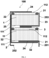
FIG. 1 is a structural diagram of a battery assembly according to a preferred embodiment of the present invention. -
FIG. 2 is an assembly diagram of a negative electrode, an insulation sheet and a negative electrode connector of a battery inFIG. 1 . -
FIG. 3 is an assembly diagram of a positive electrode and a positive electrode connector of the battery inFIG. 1 . -
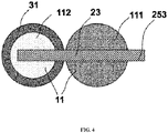
FIG. 4 is a schematic diagram illustrating an intermediate connector inFIG. 1 connected to the positive electrode and the negative electrode of two adjacent batteries respectively. -
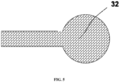
FIG. 5 is a structural diagram of a first insulation sheet. -
FIG. 6 is a structural diagram of a medical capsule according to a preferred embodiment of the present invention. - 100-battery assembly; 1-battery pack, 11-battery, 111-positive electrode, 112-negative electrode, 2-connector, 21-positive electrode connector, 22-negative electrode connector, 23-intermediate connector, 24-welding portion, 25-output portion, 251-output portion of positive electrode connector, 252-output portion of negative electrode connector, 253-output portion of intermediate connector, 3-insulation assembly, 31-insulation gasket, 32-first insulation sheet, 200-medical capsule, 4-enclosure, 5-vibration source, 6-control unit, 61-PCB, 62-reed switch, 7-fixing structure.
- The present invention is described in detail below with reference to the accompanying drawings and preferred embodiments. However, the embodiments are not intended to limit the invention, and the structural, method, or functional changes made by those skilled in the art in accordance with the embodiments are included in the scope of the present invention.
- In the figures of the present invention, some dimensions of a structure or portion may be exaggerated relative to other structures or portions for ease of illustration, and thus, are merely used to illustrate the basic structure of the subject matter of the present invention.
- In order to solve the above problem, referring to
FIGS. 1 to 5 , in the embodiments of the present invention, abattery assembly 100 comprises abattery pack 1 and a plurality ofconnectors 2 electrically connected to thebattery pack 1. The electrical connection may be realized by welding or conductive adhesive. - The
battery pack 1 comprises at least twobatteries 11 connected in series. Preferably, at least twobatteries 11 are arranged in a stack, and the number of thebatteries 11 can be adjusted according to a required output voltage. - In one embodiment, the
battery 11 is a button type silver oxide battery, which is small in size, safe and stable enough to meet safety requirements of amedical capsule 200. - The plurality of
connectors 2 comprises apositive electrode connector 21 electrically connected to apositive electrode 111 of thebattery pack 1, anegative electrode connector 22 electrically connected to thenegative electrode 112 of thebattery pack 1, and anintermediate connector 23 electrically connected to apositive electrode 111 of one of any twoadjacent batteries 11 and anegative electrode 112 of the other of any twoadjacent batteries 11. Therefore, the total voltage of thebattery pack 1 can be output through thepositive electrode connector 21 and thenegative electrode connector 22, and the voltage of part of thebattery pack 1 can be output through the cooperation of one of the positive electrode or the negative electrode with theintermediate connector 23, so as to supply power to different electrical components, or provide different voltages to the same electrical component as required. - "The voltage of part of the
battery pack 1 can be output" means that thebattery pack 1 comprises at least twobatteries 11 connected in series, and the voltages ofN batteries 11 are output through the cooperation of one of the positive electrode or the negative electrode with theintermediate connector 23, wherein N is an integer not greater than the total number of thebatteries 11 contained in thebattery pack 11. For example, thebattery pack 1 comprises twobatteries 11 connected in series, and the voltage of onebattery 11 can be output. - The number of the
batteries 11 connected in series between theintermediate connector 23 and thepositive electrode connector 21 and the number of thebatteries 11 connected in series between theintermediate connector 23 and thenegative electrode connector 22 can be adjusted according to a required output voltage. For example, onebattery 11 is connected in series between theintermediate connector 23 and thepositive electrode connector 21, or onebattery 11 is connected in series between theintermediate connector 23 and thenegative electrode connector 22, so that the voltage of asingle battery 11 can be output. - The
connector 2 further comprises awelding portion 24 welded to thebattery 11, and anoutput portion 25 connected to thewelding portion 24. Generally, thewelding portion 24 and theoutput portion 25 are integrally formed, and theoutput portion 25 can be bent into a desired shape to facilitate installation in themedical capsule 200. In this example, theconnector 2 comprises thepositive electrode connector 21, thenegative electrode connector 22 and theintermediate connector 23. - As shown in
FIG. 1 ,FIG. 2 andFIG. 3 , the structures of thepositive electrode connector 21 and thenegative electrode connector 22 are similar, and thewelding portion 24 thereof is circular, which is convenient for multiple-point welding with thebattery pack 1 and improves the welding stability. Thewelding portion 24 comprises a plurality of welding points, for example, thewelding portion 24 comprises at least four welding points, which can be welded by soldering, highpressure spot welding or laser spot welding to improve the stability of power supply. Theoutput portions - In a preferred solution, the
connector 2 is connected to the electrode of thebattery 11 by a spot welding process, preferably by the laser spot welding, which features high consistency and high degree of automation. Theconnector 2 is welded to a printed circuit board (PCB) or a load electrical element by soldering, so as to maintain the stability of welding. - Referring to
FIG. 1 andFIG. 4 , theintermediate connector 23 is strip-shaped, and the welding portion thereof is stacked between twoadjacent batteries 11 after being welded to the twoadjacent batteries 11. - Further, the
connector 2 is a nickel-plated SPCC (Cold Rolled Steel, generally using cold-rolled carbon steel sheet and steel strip) steel sheet, a nickel sheet or a copper sheet, which can be welded to the electrode of thebattery 11, the PCB and the load electrical element. Preferably, a pure nickel sheet is selected to effectively avoid cold solder joint. The pure nickel sheet is formed from pure nickel commonly mentioned in the industry, which is allowed to contain trace impurities that cannot be eliminated in the purification process, not referring to 100% pure nickel. - The output portion of the
positive electrode connector 251 and the output portion of thenegative electrode connector 252 extend towards a side of thepositive electrode 111 of thebattery pack 1 or a side of thenegative electrode 112 of thebattery pack 1, so as to be soldered to a same PCB. The output portion of theintermediate connector 253 extends towards another side of thebattery pack 1. The output portion of theintermediate connector 253 is connected to a load electrical element, so as to cooperate with the PCB to output part of voltage of thewhole battery pack 1 to the load electrical element. - In a specific embodiment, as shown in
FIGS. 1 to 5 , both the output portion of thepositive electrode connector 251 and the output portion of thenegative electrode connector 252 extend towards the side of thepositive electrode 111 of thebattery pack 1, so as to be soldered to the PCB. The output portion of theintermediate connector 253 extends towards the side of thenegative electrode 112 of thebattery pack 1. - Based on any of the above embodiments, the
battery assembly 100 further comprises aninsulation assembly 3, and those skilled in the art can understand that theinsulation assembly 3 is disposed between two components requiring insulation to avoid short circuit. For example, theinsulation assembly 3 is disposed betweenadjacent batteries 11, between theconnector 2 and thebattery 11, between thebattery pack 100 and an adjacent PCB, or between thebattery assembly 100 and other adjacent electrical components. - Specifically, the
insulation assembly 3 comprises anannular insulation gasket 31 located around thenegative electrode 112 of thebattery 11, which is adhered to thenegative electrode 112 of thebattery 11 and just covers the positive electrode part around thenegative electrode 112 of thebattery 11, so as to avoid short circuit between the positive electrode area and the negative electrode area of thebattery 11 caused by devices or other electrical contacts. For example, thenegative electrode 112 may be isolated from the positive electrode portion around thenegative electrode 112, or theconnector 2 connected to thenegative electrode 112 may be isolated from the positive electrode portion around thenegative electrode 112. - The
insulation gasket 31 is a film made of polyethylene terephthalate (PET), polyvinyl chloride (PVC), polypropylene (PP), or polyamide (PA) with backing. The thickness of theinsulation gasket 31 is 0.01 mm to 0.5 mm, preferably 0.05 mm to 0.15 mm, which can not only meet the requirements of high conformance rate, but also achieve good insulation characteristics. - As shown in
FIGS. 1 to 5 , the output portion of thepositive electrode connector 251 and the output portion of thenegative electrode connector 252 extend towards the side of thepositive electrode 111 of thebattery pack 1, and the output portion of theintermediate connector 253 extends towards the side of thenegative electrode 112 of thebattery pack 1. Insulation is required between thenegative electrode connector 22 and the side wall of thebattery pack 1. Theinsulation assembly 3 further comprises afirst insulation sheet 32 disposed on a side of the output portion of thenegative electrode connector 252 facing thebattery 11, so as to insulate thenegative electrode connector 22 from the side wall of thebattery pack 1. Preferably, thefirst insulation sheet 32 is bent and extends to a side of thepositive electrode connector 21 away from thebattery pack 1, so as to insulate and separate thewhole battery assembly 100 from the PCB. - In this embodiment, if there is only one
battery 11 between the welding portion of theintermediate connector 23 and thenegative electrode 112 of thebattery pack 1, the output portion of theintermediate connector 253 does not need to be insulated from the side wall of thebattery 11. Therefore, the side of the output portion of theintermediate connector 253 facing thebattery 11 may or may not be provided with an insulation sheet. If there are at least twobatteries 11 between the welding portion of theintermediate connector 23 and thenegative electrode 112 of thebattery pack 1, an insulation sheet should be disposed on the side of the output portion of theintermediate connector 253 facing thebatteries 11 to avoid short circuit. - Alternatively, each of the output portion of the
positive electrode connector 251 and the output portion of thenegative electrode connector 252 extends towards the side of thenegative electrode 112 of thebattery pack 1, and the output portion of theintermediate connector 253 extends towards the side of thepositive electrode 111 of thebattery pack 1. Theinsulation assembly 3 further comprises a second insulation sheet disposed on a side of the output portion of thepositive electrode connector 251 facing thebattery 11, and a third insulation sheet disposed on a side of the output portion of theintermediate connector 253 facing thebattery 11. - The
battery assembly 100 of the present invention may be used with a variety ofmedical capsules 200 including, but not limited to, vibrating capsules, endoscopic capsules, etc. - In one embodiment, referring to
FIG. 6 , themedical capsule 200 is a vibrating capsule, comprising an enclosure 4, avibration source 5 housed in the enclosure 4, thebattery assembly 100, and acontrol unit 6. Thevibration source 5, thebattery assembly 100 and thecontrol unit 6 are fixed in the enclosure 4 by a fixingstructure 7. - The enclosure 4 and the
vibration source 5 are any one of the prior art, and thebattery assembly 100 is any one of the above. - The
control unit 6 comprises aPCB 61 and areed switch 62 communicatively connected to thePCB 61. Thepositive electrode connector 21 and thenegative electrode connector 22 are electrically connected to thePCB 61. Thevibration source 5 is electrically connected to both thePCB 61 and theintermediate connector 23, so that different voltages can be output within the allowable voltage range of thevibration source 5. - In summary, the
battery assembly 100 of the present invention can output the total voltage of thebattery pack 1 through thepositive electrode connector 21 and thenegative electrode connector 22, and can also output the voltage of part of thebattery pack 1 through the cooperation of one of the positive electrode or the negative electrode and theintermediate connector 23, to power different electrical components or to supply different voltages to the same electrical component as required. - It should be understood that, although the specification is described in terms of embodiments, not every embodiment merely comprises an independent technical solution. Those skilled in the art should have the specification as a whole, and the technical solutions in each embodiment may also be combined as appropriate to form other embodiments that can be understood by those skilled in the art.
- The series of detailed descriptions set forth above are only specific to a feasible embodiment of the present invention and are not intended to limit the scope of protection of the present invention, and any equivalent embodiments or variations made without departing from the spirit of the art of the present invention shall be included within the scope of protection of the present invention.
Claims (15)
- A battery assembly, comprises:a battery pack comprising at least two batteries connected in series; anda plurality of connectors electrically connected to the battery pack, comprising a positive electrode connector electrically connected to a positive electrode of the battery pack, a negative electrode connector electrically connected to a negative electrode of the battery pack, and an intermediate connector electrically connected to a positive electrode of one of any two adjacent batteries and a negative electrode of the other of the two adjacent batteries.
- The battery assembly of claim 1, wherein the battery is a silver oxide battery.
- The battery assembly of claim 1, wherein the connector is a nickel-plated SPCC steel sheet, a nickel sheet or a copper sheet.
- The battery assembly of claim 1, wherein each of the positive electrode connector, the negative electrode connector and the intermediate connector comprises a welding portion welded to an electrode of the battery and an output portion connected to the welding portion.
- The battery assembly of claim 4, wherein the output portion of the positive electrode connector and the output portion of the negative electrode connector extend towards a side of the positive electrode of the battery pack or a side of the negative electrode of the battery pack , and the output portion of the intermediate connector extends towards another side of the battery pack .
- The battery assembly of claim 1, wherein the battery assembly further comprises an insulation assembly arranged between adjacent batteries or between the connector and the batteries .
- The battery assembly of claim 6, wherein the insulation assembly comprises an insulation gasket disposed around the negative electrode of the battery ;or, each of the positive electrode connector , the negative electrode connector and the intermediate connector comprises a welding portion welded to an electrode of the battery and an output portion connected to the welding portion ; wherein the output portion of the positive electrode connector and the output portion of the negative electrode connector extend towards a side of the positive electrode of the battery pack , and the output portion of the intermediate connector extends towards a side of the negative electrode of the battery pack ; wherein the insulation assembly further comprises a first insulation sheet disposed on the side of the output portion of the negative electrode connector facing the battery ; wherein an insulation sheet is or is not disposed on the side of the output portion of the intermediate connector facing the battery when one battery is arranged between the welding portion of the intermediate connector and the negative electrode of the battery pack ; and wherein an insulation sheet is disposed on the side of the output portion of the intermediate connector facing the batteries when at least two batteries are arranged between the welding portion of the intermediate connector and the negative electrode of the battery pack;or, each of the positive electrode connector , the negative electrode connector , and the intermediate connector comprises the welding portion welded to an electrode of the battery and the output portion connected to the welding portion ; wherein the output portion of the positive electrode connector and the output portion of the negative electrode connector both extend towards the side of the negative electrode of the battery pack , and the output portion of the intermediate connector extends towards the side of the positive electrode of the battery pack ; and wherein the insulation assembly also comprises a second insulation sheet and a third insulation sheet, wherein the second insulation sheet is disposed on the side of the output portion of the positive electrode connector facing the battery , and the third insulation sheet is disposed on the side of the output portion of the intermediate connector facing the battery .
- A medical capsule , comprises the battery assembly of claim 1.
- The medical capsule of claim 8, wherein the medical capsule is a vibrating capsule, and further comprises an enclosure, a vibration source and a control unit, wherein the vibration source and the control unit are housed in the enclosure, the control unit comprises a PCB , the positive electrode connector and the negative electrode connector are both electrically connected to the PCB , and the vibration source is electrically connected to both the PCB and the intermediate connector .
- The medical capsule of claim 8, wherein the battery is a silver oxide battery.
- The medical capsule of claim 8, wherein the connector is a nickel-plated SPCC steel sheet, a nickel sheet or a copper sheet.
- The medical capsule of claim 8, wherein each of the positive electrode connector , the negative electrode connector and the intermediate connector comprises a welding portion welded to an electrode of the battery and an output portion connected to the welding portion .
- The medical capsule of claim 12, wherein the output portion of the positive electrode connector and the output portion of the negative electrode connector extend towards a side of the positive electrode of the battery pack or a side of the negative electrode of the battery pack , and the output portion of the intermediate connector extends towards another side of the battery pack .
- The medical capsule of claim 9, wherein the battery assembly further comprises an insulation assembly arranged between adjacent batteries or between the connector and the batteries .
- The medical capsule of claim 14, wherein the insulation assembly comprises an insulation gasket disposed around the negative electrode of the battery ;or, each of the positive electrode connector , the negative electrode connector and the intermediate connector comprises a welding portion welded to an electrode of the battery and an output portion connected to the welding portion ; wherein the output portion of the positive electrode connector and the output portion of the negative electrode connector extend towards a side of the positive electrode of the battery pack , and the output portion of the intermediate connector extends towards a side of the negative electrode of the battery pack ; wherein the insulation assembly further comprises a first insulation sheet disposed on the side of the output portion of the negative electrode connector facing the battery ; wherein an insulation sheet is or is not disposed on the side of the output portion of the intermediate connector facing the battery when one battery is arranged between the welding portion of the intermediate connector and the negative electrode of the battery pack ; and wherein an insulation sheet is disposed on the side of the output portion of the intermediate connector facing the batteries when at least two batteries are arranged between the welding portion of the intermediate connector and the negative electrode of the battery pack;or, each of the positive electrode connector , the negative electrode connector , and the intermediate connector comprises the welding portion welded to an electrode of the battery and the output portion connected to the welding portion ; wherein the output portion of the positive electrode connector and the output portion of the negative electrode connector both extend towards the side of the negative electrode of the battery pack , and the output portion of the intermediate connector extends towards the side of the positive electrode of the battery pack ; and wherein the insulation assembly also comprises a second insulation sheet and a third insulation sheet, wherein the second insulation sheet is disposed on the side of the output portion of the positive electrode connector facing the battery , and the third insulation sheet is disposed on the side of the output portion of the intermediate connector facing the battery .
Applications Claiming Priority (2)
| Application Number | Priority Date | Filing Date | Title |
|---|---|---|---|
| CN202010486148.6A CN111490211A (en) | 2020-06-01 | 2020-06-01 | Battery components and medical capsules |
| PCT/CN2021/096832 WO2021244432A1 (en) | 2020-06-01 | 2021-05-28 | Battery assembly and medical capsule |
Publications (2)
| Publication Number | Publication Date |
|---|---|
| EP4160809A1 true EP4160809A1 (en) | 2023-04-05 |
| EP4160809A4 EP4160809A4 (en) | 2024-08-07 |
Family
ID=71813416
Family Applications (1)
| Application Number | Title | Priority Date | Filing Date |
|---|---|---|---|
| EP21818676.5A Withdrawn EP4160809A4 (en) | 2020-06-01 | 2021-05-28 | BATTERY ARRANGEMENT AND MEDICAL CAPSULE |
Country Status (6)
| Country | Link |
|---|---|
| US (1) | US20230346197A1 (en) |
| EP (1) | EP4160809A4 (en) |
| JP (1) | JP7644147B2 (en) |
| KR (1) | KR20230018464A (en) |
| CN (1) | CN111490211A (en) |
| WO (1) | WO2021244432A1 (en) |
Families Citing this family (3)
| Publication number | Priority date | Publication date | Assignee | Title |
|---|---|---|---|---|
| CN111490211A (en) * | 2020-06-01 | 2020-08-04 | 上海安翰医疗技术有限公司 | Battery components and medical capsules |
| CN114631768B (en) * | 2022-05-23 | 2026-04-10 | 安翰科技(武汉)股份有限公司 | capsule endoscopy |
| CN114639924B (en) * | 2022-05-23 | 2022-08-23 | 安翰科技(武汉)股份有限公司 | Battery mounting assembly and capsule endoscope |
Family Cites Families (17)
| Publication number | Priority date | Publication date | Assignee | Title |
|---|---|---|---|---|
| JPS562350Y2 (en) * | 1975-01-17 | 1981-01-20 | ||
| JP3336653B2 (en) * | 1993-01-16 | 2002-10-21 | ソニー株式会社 | Battery pack |
| JP2000138046A (en) * | 1998-10-30 | 2000-05-16 | Toshiba Battery Co Ltd | Sealed battery |
| CN104078630B (en) * | 2009-12-24 | 2017-02-08 | 三洋电机株式会社 | Battery pack |
| KR101283347B1 (en) * | 2010-09-07 | 2013-07-10 | 주식회사 엘지화학 | High-Output, Large-Capacity Battery Pack |
| CN201796976U (en) * | 2010-09-27 | 2011-04-13 | 张卫 | Variable voltage battery box |
| JP5835885B2 (en) * | 2010-11-12 | 2015-12-24 | オリンパス株式会社 | Capsule endoscope |
| US8609266B2 (en) * | 2011-02-18 | 2013-12-17 | Samsung Sdi Co., Ltd. | Battery pack |
| CN102545310A (en) * | 2011-11-29 | 2012-07-04 | 卢小平 | Power supply method and power supply device for underwater electric toys |
| EP2859832A4 (en) * | 2012-06-08 | 2016-03-02 | Olympus Corp | MEDICAL DEVICE OF THE CAPSULE TYPE |
| KR102099572B1 (en) * | 2013-12-03 | 2020-04-10 | 삼성에스디아이 주식회사 | Battery Pack |
| CN105877980B (en) * | 2015-04-27 | 2019-04-19 | 上海安翰医疗技术有限公司 | Physical therapy device and its control method inside alimentary canal |
| JP6654031B2 (en) * | 2015-12-14 | 2020-02-26 | セイコーインスツル株式会社 | Small electronic equipment |
| US10500127B2 (en) * | 2016-04-18 | 2019-12-10 | Ankon Medical Technologies (Shanghai) Co., Ltd. | Vivo device and method of using the same |
| US10541403B2 (en) * | 2016-10-14 | 2020-01-21 | Tiveni Mergeco, Inc. | Cylindrical battery cell configured with insulation component, and battery module containing the same |
| CN111490211A (en) * | 2020-06-01 | 2020-08-04 | 上海安翰医疗技术有限公司 | Battery components and medical capsules |
| CN212342708U (en) * | 2020-06-01 | 2021-01-12 | 上海安翰医疗技术有限公司 | Battery pack and medical capsule |
-
2020
- 2020-06-01 CN CN202010486148.6A patent/CN111490211A/en active Pending
-
2021
- 2021-05-28 JP JP2022574239A patent/JP7644147B2/en active Active
- 2021-05-28 EP EP21818676.5A patent/EP4160809A4/en not_active Withdrawn
- 2021-05-28 KR KR1020227046047A patent/KR20230018464A/en not_active Ceased
- 2021-05-28 WO PCT/CN2021/096832 patent/WO2021244432A1/en not_active Ceased
- 2021-05-28 US US18/007,731 patent/US20230346197A1/en active Pending
Also Published As
| Publication number | Publication date |
|---|---|
| WO2021244432A1 (en) | 2021-12-09 |
| KR20230018464A (en) | 2023-02-07 |
| CN111490211A (en) | 2020-08-04 |
| EP4160809A4 (en) | 2024-08-07 |
| JP7644147B2 (en) | 2025-03-11 |
| JP2023528840A (en) | 2023-07-06 |
| US20230346197A1 (en) | 2023-11-02 |
Similar Documents
| Publication | Publication Date | Title |
|---|---|---|
| EP4160809A1 (en) | Battery assembly and medical capsule | |
| KR102303827B1 (en) | Complex electrode assembly including a plurality of electrode assemblies and electrochemical device comprising the complex electrode assembly | |
| JP7603264B2 (en) | Electricity storage device and electricity storage module | |
| RU2332751C1 (en) | Electrodes connector containing plate and battery module used with it | |
| EP2219248A1 (en) | Electrode sheet, secondary battery and method for manufacturing the secondary battery | |
| JP5609905B2 (en) | Power storage device, secondary battery and vehicle | |
| US9184472B2 (en) | Battery pack and method of manufacturing battery pack with interconnected half contact pads | |
| TW200308113A (en) | Method for treating electrode tabs of crude cell for lithium secondary battery and crude cell and lithium secondary battery according to the method | |
| US10665395B2 (en) | Power storage device | |
| US11404682B2 (en) | Non-rectangular shaped electrodes utilizing complex shaped insulation | |
| KR20140104435A (en) | Electrical energy storage module and method for producing an electrical energy storage module | |
| US20190044122A1 (en) | Electric storage device | |
| JP2020524371A (en) | Battery module and manufacturing method thereof | |
| JP2013214464A (en) | Battery | |
| US20120106026A1 (en) | Electrical storage device | |
| CN212342708U (en) | Battery pack and medical capsule | |
| JP2021516436A (en) | Rechargeable battery and battery module | |
| JP7150714B2 (en) | BATTERY MODULE AND BATTERY MODULE MANUFACTURING METHOD | |
| CN218351514U (en) | Folding electrode, battery pack and electrical appliance | |
| KR20190112581A (en) | Voltage sensing module of terminal using elasticity and battery module comprising the same | |
| JP2019117703A (en) | Power storage element | |
| KR20130091086A (en) | Secondary battery of novel structure | |
| CN115084626A (en) | Battery device assembly method and battery device | |
| CN223514187U (en) | Battery module and electric equipment | |
| JP6261695B1 (en) | Storage module manufacturing method and storage module |
Legal Events
| Date | Code | Title | Description |
|---|---|---|---|
| STAA | Information on the status of an ep patent application or granted ep patent |
Free format text: STATUS: THE INTERNATIONAL PUBLICATION HAS BEEN MADE |
|
| PUAI | Public reference made under article 153(3) epc to a published international application that has entered the european phase |
Free format text: ORIGINAL CODE: 0009012 |
|
| STAA | Information on the status of an ep patent application or granted ep patent |
Free format text: STATUS: REQUEST FOR EXAMINATION WAS MADE |
|
| 17P | Request for examination filed |
Effective date: 20221230 |
|
| AK | Designated contracting states |
Kind code of ref document: A1 Designated state(s): AL AT BE BG CH CY CZ DE DK EE ES FI FR GB GR HR HU IE IS IT LI LT LU LV MC MK MT NL NO PL PT RO RS SE SI SK SM TR |
|
| DAV | Request for validation of the european patent (deleted) | ||
| DAX | Request for extension of the european patent (deleted) | ||
| A4 | Supplementary search report drawn up and despatched |
Effective date: 20240708 |
|
| RIC1 | Information provided on ipc code assigned before grant |
Ipc: A61H 23/02 20060101ALI20240702BHEP Ipc: H01M 50/502 20210101AFI20240702BHEP |
|
| STAA | Information on the status of an ep patent application or granted ep patent |
Free format text: STATUS: THE APPLICATION IS DEEMED TO BE WITHDRAWN |
|
| 18D | Application deemed to be withdrawn |
Effective date: 20250128 |