EP4160789A1 - Battery pack - Google Patents
Battery pack Download PDFInfo
- Publication number
- EP4160789A1 EP4160789A1 EP22198099.8A EP22198099A EP4160789A1 EP 4160789 A1 EP4160789 A1 EP 4160789A1 EP 22198099 A EP22198099 A EP 22198099A EP 4160789 A1 EP4160789 A1 EP 4160789A1
- Authority
- EP
- European Patent Office
- Prior art keywords
- inlet pipe
- outlet pipe
- pipe
- battery pack
- cooling plate
- Prior art date
- Legal status (The legal status is an assumption and is not a legal conclusion. Google has not performed a legal analysis and makes no representation as to the accuracy of the status listed.)
- Granted
Links
Images



Classifications
-
- H—ELECTRICITY
- H01—ELECTRIC ELEMENTS
- H01M—PROCESSES OR MEANS, e.g. BATTERIES, FOR THE DIRECT CONVERSION OF CHEMICAL ENERGY INTO ELECTRICAL ENERGY
- H01M10/00—Secondary cells; Manufacture thereof
- H01M10/60—Heating or cooling; Temperature control
- H01M10/65—Means for temperature control structurally associated with the cells
- H01M10/655—Solid structures for heat exchange or heat conduction
- H01M10/6556—Solid parts with flow channel passages or pipes for heat exchange
-
- H—ELECTRICITY
- H01—ELECTRIC ELEMENTS
- H01M—PROCESSES OR MEANS, e.g. BATTERIES, FOR THE DIRECT CONVERSION OF CHEMICAL ENERGY INTO ELECTRICAL ENERGY
- H01M10/00—Secondary cells; Manufacture thereof
- H01M10/60—Heating or cooling; Temperature control
- H01M10/61—Types of temperature control
- H01M10/613—Cooling or keeping cold
-
- H—ELECTRICITY
- H01—ELECTRIC ELEMENTS
- H01M—PROCESSES OR MEANS, e.g. BATTERIES, FOR THE DIRECT CONVERSION OF CHEMICAL ENERGY INTO ELECTRICAL ENERGY
- H01M10/00—Secondary cells; Manufacture thereof
- H01M10/60—Heating or cooling; Temperature control
- H01M10/62—Heating or cooling; Temperature control specially adapted for specific applications
- H01M10/625—Vehicles
-
- H—ELECTRICITY
- H01—ELECTRIC ELEMENTS
- H01M—PROCESSES OR MEANS, e.g. BATTERIES, FOR THE DIRECT CONVERSION OF CHEMICAL ENERGY INTO ELECTRICAL ENERGY
- H01M10/00—Secondary cells; Manufacture thereof
- H01M10/60—Heating or cooling; Temperature control
- H01M10/65—Means for temperature control structurally associated with the cells
- H01M10/653—Means for temperature control structurally associated with the cells characterised by electrically insulating or thermally conductive materials
-
- H—ELECTRICITY
- H01—ELECTRIC ELEMENTS
- H01M—PROCESSES OR MEANS, e.g. BATTERIES, FOR THE DIRECT CONVERSION OF CHEMICAL ENERGY INTO ELECTRICAL ENERGY
- H01M10/00—Secondary cells; Manufacture thereof
- H01M10/60—Heating or cooling; Temperature control
- H01M10/65—Means for temperature control structurally associated with the cells
- H01M10/655—Solid structures for heat exchange or heat conduction
- H01M10/6554—Rods or plates
-
- H—ELECTRICITY
- H01—ELECTRIC ELEMENTS
- H01M—PROCESSES OR MEANS, e.g. BATTERIES, FOR THE DIRECT CONVERSION OF CHEMICAL ENERGY INTO ELECTRICAL ENERGY
- H01M10/00—Secondary cells; Manufacture thereof
- H01M10/60—Heating or cooling; Temperature control
- H01M10/65—Means for temperature control structurally associated with the cells
- H01M10/656—Means for temperature control structurally associated with the cells characterised by the type of heat-exchange fluid
- H01M10/6567—Liquids
-
- H—ELECTRICITY
- H01—ELECTRIC ELEMENTS
- H01M—PROCESSES OR MEANS, e.g. BATTERIES, FOR THE DIRECT CONVERSION OF CHEMICAL ENERGY INTO ELECTRICAL ENERGY
- H01M10/00—Secondary cells; Manufacture thereof
- H01M10/60—Heating or cooling; Temperature control
- H01M10/65—Means for temperature control structurally associated with the cells
- H01M10/656—Means for temperature control structurally associated with the cells characterised by the type of heat-exchange fluid
- H01M10/6567—Liquids
- H01M10/6568—Liquids characterised by flow circuits, e.g. loops, located externally to the cells or cell casings
-
- H—ELECTRICITY
- H01—ELECTRIC ELEMENTS
- H01M—PROCESSES OR MEANS, e.g. BATTERIES, FOR THE DIRECT CONVERSION OF CHEMICAL ENERGY INTO ELECTRICAL ENERGY
- H01M50/00—Constructional details or processes of manufacture of the non-active parts of electrochemical cells other than fuel cells, e.g. hybrid cells
- H01M50/20—Mountings; Secondary casings or frames; Racks, modules or packs; Suspension devices; Shock absorbers; Transport or carrying devices; Holders
- H01M50/204—Racks, modules or packs for multiple batteries or multiple cells
-
- H—ELECTRICITY
- H01—ELECTRIC ELEMENTS
- H01M—PROCESSES OR MEANS, e.g. BATTERIES, FOR THE DIRECT CONVERSION OF CHEMICAL ENERGY INTO ELECTRICAL ENERGY
- H01M50/00—Constructional details or processes of manufacture of the non-active parts of electrochemical cells other than fuel cells, e.g. hybrid cells
- H01M50/30—Arrangements for facilitating escape of gases
- H01M50/35—Gas exhaust passages comprising elongated, tortuous or labyrinth-shaped exhaust passages
-
- H—ELECTRICITY
- H01—ELECTRIC ELEMENTS
- H01M—PROCESSES OR MEANS, e.g. BATTERIES, FOR THE DIRECT CONVERSION OF CHEMICAL ENERGY INTO ELECTRICAL ENERGY
- H01M50/00—Constructional details or processes of manufacture of the non-active parts of electrochemical cells other than fuel cells, e.g. hybrid cells
- H01M50/30—Arrangements for facilitating escape of gases
- H01M50/35—Gas exhaust passages comprising elongated, tortuous or labyrinth-shaped exhaust passages
- H01M50/358—External gas exhaust passages located on the battery cover or case
-
- H—ELECTRICITY
- H01—ELECTRIC ELEMENTS
- H01M—PROCESSES OR MEANS, e.g. BATTERIES, FOR THE DIRECT CONVERSION OF CHEMICAL ENERGY INTO ELECTRICAL ENERGY
- H01M50/00—Constructional details or processes of manufacture of the non-active parts of electrochemical cells other than fuel cells, e.g. hybrid cells
- H01M50/30—Arrangements for facilitating escape of gases
- H01M50/35—Gas exhaust passages comprising elongated, tortuous or labyrinth-shaped exhaust passages
- H01M50/367—Internal gas exhaust passages forming part of the battery cover or case; Double cover vent systems
-
- Y—GENERAL TAGGING OF NEW TECHNOLOGICAL DEVELOPMENTS; GENERAL TAGGING OF CROSS-SECTIONAL TECHNOLOGIES SPANNING OVER SEVERAL SECTIONS OF THE IPC; TECHNICAL SUBJECTS COVERED BY FORMER USPC CROSS-REFERENCE ART COLLECTIONS [XRACs] AND DIGESTS
- Y02—TECHNOLOGIES OR APPLICATIONS FOR MITIGATION OR ADAPTATION AGAINST CLIMATE CHANGE
- Y02E—REDUCTION OF GREENHOUSE GAS [GHG] EMISSIONS, RELATED TO ENERGY GENERATION, TRANSMISSION OR DISTRIBUTION
- Y02E60/00—Enabling technologies; Technologies with a potential or indirect contribution to GHG emissions mitigation
- Y02E60/10—Energy storage using batteries
Definitions
- the present disclosure relates to a battery pack.
- a secondary battery is a battery capable of charging and discharging electricity, and has a wide application range, including to relatively small portable electronic devices, mid-sized to large-sized automobiles, and power storage devices.
- a secondary battery may be used as a secondary battery cell, and the secondary battery cell may have a configuration in which a stack body, including a positive electrode, a negative electrode, and a separator, is disposed in an exterior material and an electrolyte fills the inside of the exterior material.
- a stack body including a positive electrode, a negative electrode, and a separator
- an electrolyte fills the inside of the exterior material.
- a plurality of secondary battery cells arranged to be dense in a battery pack, may be overcharged and exposed to various events such as a high-temperature external environment at any time, so that the battery pack may have a risk of ignition or explosion.
- An aspect of the present disclosure is to improve cooling efficiency of a battery cell.
- Another aspect of the present disclosure is to improve assembly efficiency and space utilization efficiency of a battery cell.
- a battery pack includes: a first cooling plate including a first cooling path, along which a refrigerant is circulated, and a first inlet pipe connected to the first cooling path; a second cooling plate including a second cooling path, along which a refrigerant is circulated, and a second inlet pipe connected to the second cooling path and sealingly coupled to the first inlet pipe; a main supply pipe branching from the first inlet pipe or the second inlet pipe and supplying a refrigerant to the first inlet pipe and the second inlet pipe; and a pack unit body including at least one battery cell and disposed between the first cooling plate and the second cooling plate.
- the first cooling plate may further include a first outlet pipe connected to the first cooling path
- the second cooling plate may further include a second outlet pipe connected to the second cooling path and sealingly coupled to the first outlet pipe.
- the battery pack may further include a main outlet pipe branching from the first outlet pipe or the second outlet pipe and discharging a refrigerant, received from the first outlet pipe and the second outlet pipe, to the outside.
- the first inlet pipe may be coupled to the second inlet pipe in a coupling direction, parallel to a height direction of the battery cell.
- the main supply pipe and the main outlet pipe may allow a refrigerant to flow in a first flow direction, perpendicular to the coupling direction.
- the first inlet pipe, the first outlet pipe, the second inlet pipe, and the second outlet pipe may allow a refrigerant to flow in a second flow direction, parallel to the coupling direction.
- At least one of the first inlet pipe and the first outlet pipe may be provided such that an external diameter in a coupling portion to at least one of the second inlet pipe and the second outlet pipe is smaller than an internal diameter in a coupling portion to at least one of the second inlet pipe and the second outlet pipe.
- the first inlet pipe and the first outlet pipe may be fitted and coupled to the second inlet pipe and the second outlet pipe, respectively.
- the first inlet pipe and the first outlet pipe may be provided to have a loose fit tolerance or a medium fit tolerance to the second inlet pipe and the second outlet pipe, respectively.
- the battery pack may further include: a sealing member disposed in at least one of a position between an external surface of the first inlet pipe and an internal surface of the second inlet pipe and a position between an external surface of the first outlet pipe and an internal surface of the second outlet pipe.
- the battery pack may further include: a side frame facing the pack unit body; and a cover member disposed between the first cooling plate or the second cooling plate and the pack unit body to cover the pack unit body.
- the cover member may be disposed between the first cooling plate and the back unit body, and the battery pack may further include a heat transfer material disposed in at least one of a position between the cover member and the first cooling plate and a position between the cover member and the pack unit body.
- the heat transfer material may also be disposed between the pack unit body and the second cooling plate.
- At least one of the first inlet pipe, the first outlet pipe, the second inlet pipe, the second outlet pipe, the main supply pipe, and the main outlet pipe may be provided to be flexible.
- the side frame may have a first venting hole and a second venting hole connected to the outside, and the side frame may further include a partition wall frame having a third venting hole connected to the first venting hole and connected to the side frame such that the third venting hole faces the pack unit body.
- FIG. 1 is a schematic cross-sectional view of a battery pack according to an embodiment of the present disclosure.
- a battery pack may include a first cooling plate 110 having a first cooling path 111 therein, a second cooling plate 120 having a second cooling path 121 therein, and a pack unit body 140 interposed between the first cooling plate 110 and the second cooling plate 120.
- a refrigerant for cooling may be present in each of the first cooling path 111 and the second cooling path 121.
- Water may be used as the refrigerant, but the type of the refrigerant is not limited by the present disclosure and may be appropriately selected and applied according to usage environments, capacity, and the like, of the battery pack.
- the first cooling plate 110, the second cooling plate 120, and the pack unit body 140 may be disposed in a direction, parallel to an X-axis, and may be stacked in a direction, parallel to a Y-axis. Each of the first cooling plate 110 and the second cooling plate 120 may be in contact with the pack unit body 140.
- the first cooling plate 110 may include a first inlet pipe 112 connected to the first cooling path 111 and extending in a negative Y-direction.
- the first inlet pipe 112 may be provided to allow the refrigerant to flow therein.
- the refrigerant may be introduced into the first cooling path 111 through the first inlet pipe 112.
- the second cooling plate 120 may include a second inlet pipe 122 connected to the second cooling path 121 and extending in a positive Y-direction.
- the second inlet pipe 122 may be provided to allow the refrigerant to flow therein.
- the second inlet pipe 122 may be sealingly coupled to the first inlet pipe 112, and may be separated from the first inlet pipe 112, as necessary.
- the refrigerant may be introduced into the second cooling path 121 through the second inlet pipe 122.
- the first cooling path 111 and the first inlet pipe 112 may be sealingly coupled to each other, and the second cooling path 121 and the second inlet pipe 122 may be sealingly coupled to each other.
- a sealing component such as an O-ring (not illustrated), may be used for sealingly coupling between the first cooling path 111 and the first inlet pipe 112 and between the second cooling path 121 and the second inlet pipe 122.
- a bracket for coupling (not illustrated) may be used as the sealing component, but exemplary embodiments are not limited thereto.
- the structure, in which the first cooling path 111 and the second cooling path 112 are respectively provided in the first cooling plate 110 and the second cooling plate 120, is not limited by the present disclosure.
- the first cooling path 111 and the second cooling path 121 may be respectively provided, in an appropriate form, in the first cooling plate 110 and the second cooling plate 120.
- a coupling direction a direction in which the first inlet pipe 112 and the second inlet pipe 122 are coupled to each other, may be perpendicular to the first cooling path 111.
- the coupling direction may be parallel to a Y-axis illustrated in FIG. 1 .
- the coupling direction may be parallel to a height direction of a battery cell 141.
- a separation direction a direction in which the first inlet pipe 112 and the second inlet pipe 122 are separated from each other while being coupled to each other, may be perpendicular to the first cooling path 111.
- the separation direction may be parallel to a Y-axis illustrated in FIG. 1 .
- the coupling direction is a negative Y-direction
- the separation direction may be a positive Y-direction.
- the coupling of the first inlet pipe 112 and the second inlet pipe 122 may be completed by seating the pack unit body 140 on the second cooling plate 120 and covering the first cooling plate 110 with the pack unit body 140. This may contribute to improvement of assembly efficiency of the battery pack.
- the main supply pipe 130 may branch from the second inlet pipe 122 in a direction, parallel to the second cooling path 121.
- the main supply pipe 130 may be provided to allow the refrigerant to flow therein.
- a flow path, provided in the main supply pipe 130, may be disposed in a direction, parallel to the second cooling path 121.
- the main supply pipe 130 may branch from the first inlet pipe 112.
- a cooling structure of the battery pack may be completed only by coupling the first inlet pipe 112 and the second inlet pipe 122 to each other without an additional fastening component. Accordingly, components required to assemble the battery pack may significantly decrease in size, and manufacturing costs may be reduced.
- the main supply pipe 130 may be formed to be integrated with the first inlet pipe 112 or the second inlet pipe 122.
- the number of mounted battery cells 141 may be increased as compared with the same volume.
- unnecessary components may be excluded to reduce a weight of the battery pack.
- the main supply pipe 130 may be connected to the pump 160.
- the pump 160 may receive the refrigerant from a tank (not illustrated) in which the refrigerant is stored, and may supply the received refrigerant to the main supply pipe 130.
- the pump 160 may be provided in a vehicle provided with a battery pack.
- exemplary embodiments are not limited thereto, and the pump 160 may be replaced with another power generation unit according to characteristics of a mechanical apparatus in which the battery pack is mounted.
- FIG. 2 is a partially perspective view of a battery pack according to an embodiment of the present disclosure.
- the first cooling plate 110 may include a first outlet pipe 113 connected to the first cooling path (111 of FIG. 1 ) in a region, different from a region in which the first inlet pipe 112 is disposed.
- the second cooling plate 120 may include a second outlet pipe 123 connected to the second cooling path (121 of FIG. 1 ) in a region, different from a region in which the second inlet pipe 122 is disposed.
- the second outlet pipe 123 may be sealingly coupled to the first outlet pipe 113.
- the first outlet pipe 113 and the second outlet pipe 123 may be coupled to each other in a direction, parallel to a Y-axis, and may be separated from each other in a direction, parallel to the Y-axis.
- the first outlet pipe 113 may be a path by which the refrigerant of the first cooling path (111 of FIG. 1 ) is discharged outwardly of the first cooling plate 110.
- the second outlet pipe 123 may be a path by which the refrigerant of the second cooling path (121 of FIG. 1 ) is discharged outwardly of the second cooling plate 120.
- the main outlet pipe 150 may branch from the first outlet pipe 113 or the second outlet pipe 123.
- the battery pack according to an embodiment may include a main outlet pipe 150 branching from the second outlet pipe 123.
- the main outlet pipe 150 may branch from the first outlet pipe 113.
- a cooling structure of the battery pack may be completed only by coupling the first outlet pipe 113 and the second outlet pipe 123 to each other without an additional fastening component. Accordingly, components required to assemble the battery pack may significantly decrease in size, and manufacturing costs may be reduced.
- the main outlet pipe 150 may be formed to be integrated with the first outlet pipe 113 or the second outlet pipe 123.
- the main outlet pipe 150 may be provided to discharge the refrigerant, supplied from the first outlet pipe 113 and the second outlet pipe 123, to the outside of the main outlet pipe 150.
- a drain pipe (not illustrated) may be additionally connected to the main outlet pipe 150 to collect refrigerant, and the collected refrigerant may be supplied to an additional heat exchange device (not illustrated). Accordingly, the refrigerant may be circulated in the first cooling path (111 of FIG. 1 ) and the second cooling path (121 of FIG. 1 ), and the cooling efficiency of the battery cell (141 of FIG. 1 ) may be improved.
- first inlet pipe 112, the second inlet pipe 122, the first outlet pipe 113, and the second outlet pipe 123 may be disposed in a front end region of the first cooling plate 110 or the second cooling plate 120.
- first inlet pipe 112 the second inlet pipe 122, the first outlet pipe 113, and the second outlet pipe 123 may be present on a lower surface or an upper surface of the cooling plate 110 or the second cooling plate 120.
- first inlet pipe 112, the second inlet pipe 122, the first outlet pipe 113 and the second outlet pipe 123 may be present outside a periphery of the back unit body (140 of FIG. 1 ) on the first cooling plate 110 or the second cooling plate 120. Accordingly, a cooling structure, capable of significantly reducing a volume of the battery pack, may be implemented.
- FIG. 3 is an enlarged cross-sectional view of front end regions of the first cooling plate 110 and the second cooling plate 120, and is a cross-sectional view of the first inlet pipe 112 and the second inlet pipe 122.
- a flow path, by which the refrigerant flows in the main supply pipe 130, may be connected to a flow path, by which the refrigerant is introduced from the first inlet pipe 112, and a flow path by which the refrigerant flows in the second inlet pipe 122.
- the refrigerant may flow in a first flow direction D1.
- the refrigerant, present in the main supply pipe 130 may be introduced into the first inlet pipe 112 and the second inlet pipe 122 by a pressure provided by the pump (160 of FIG. 1 ).
- the refrigerant may flow in a second flow direction.
- the second flow direction may be parallel to a direction in which the first inlet pipe 112 is coupled to the second inlet pipe 122, and may be perpendicular to the first flow direction.
- the second flow direction may include a second upper flow direction D21, a flow direction in the first inlet pipe 112, and a second lower flow direction D22, a flow direction in the second inlet pipe 122.
- the refrigerant may flow in the second upper flow direction D21 to be supplied to the first cooling path 111.
- the refrigerant may flow in the second lower flow direction D22 to be supplied to the second cooling path 121.
- a diameter of the flow path, by which the refrigerant flows in the first inlet pipe 112, and a diameter of the flow path, by which the refrigerant flows in the second inlet pipe 122, may be the same. Accordingly, the refrigerant may be uniformly distributed to the first cooling path 111 and the second cooling path 121.
- the refrigerant, present in the first cooling path 111 may be discharged through the first outlet pipe (113 of FIG. 2 ).
- the refrigerant, present in the second cooling path 121 may be discharged through the second outlet pipe (123 of FIG.).
- the refrigerant of the first outlet pipe (113 of FIG. 2 ) and the second outlet pipe (123 of FIG. 2 ) meet in the main outlet pipe (150 of FIG. 2 ), and may be finally discharged outwardly of the first cooling plate 110 and the second cooling plate 120 through the main outlet pipe (150 of FIG. 2 ).
- the battery cell 141 disposed to be followed by the first inlet pipe 112 and the second inlet pipe 122 in an X-axis direction, may have a side surface surrounded by a side frame 170.
- the side frame 170 may be in contact with the first cooling plate 110 and the second cooling plate 120 to protect the side surface of the battery cell 141.
- the side frame 170 may partition a space, in which the battery cell 141 is installed, and a space in which the first inlet pipe 112, the second inlet pipe 122, the first outlet pipe (113 of FIG. 2 ), and the second outlet pipe ( FIG. 2 of 123) are installed.
- the side frame 170 may prevent the refrigerant from being introduced into the battery cell 141 even when the refrigerant is discharged from the front end regions of the first cooling plate 110 and the second cooling plate 120.
- FIG. 4 is a cross-sectional view of the first inlet pipe 112 according to an embodiment of the present disclosure.
- the first inlet pipe 112 may have an internal flow path 112c provided therein, and a refrigerant may flow in the internal flow path 112c.
- the first inlet pipe 112 may have one side provided with a first flange 112d protruding in a positive X-direction and a negative X-direction.
- the first flange 112d may be in contact with the first cooling plate (110 of FIG. 3 ), and components such as a bolt (not illustrated), and the like, may pass through the first flange 112d.
- the first flange 112d may be welded to the first cooling plate (110 of FIG. 3 ) . According to the first flange 112d, the first inlet pipe 112 may be easily coupled to the first cooling plate (110 of FIG. 3 ) .
- the first inlet pipe 112 may have the other side provided with a plurality of projections 112a protruding in the positive X-direction and the negative X-direction.
- a region in which the projection 112a is present may be a coupling portion to the second inlet pipe (122 of FIG. 3 ) .
- an external diameter 112b of the region in which the projection 112a is present may be smaller than an internal diameter (122a of FIG. 5 ) of the second inlet pipe (122 of FIG. 5 ). Accordingly, the first inlet pipe 112 may be fitted and coupled to the second inlet pipe (122 of FIG. 3 ).
- the fitting coupling may contribute to improvement of assembling properties of the first inlet pipe 112 and the second inlet pipe (122 of FIG. 3 ).
- a sealing member 114 may be provided on an external surface of the first inlet pipe 112.
- the sealing member 114 may be disposed between the external surface of the first inlet pipe 112 and an internal surface of the second inlet pipe (122 of FIG. 3 ) to prevent the refrigerant from being discharged.
- the sealing member 114 may be formed of a material including rubber, urethane, or the like. However, exemplary embodiments are not limited thereto, and the material of the sealing member 114 may be appropriately changed and applied depending on the type of refrigerant, usage environments of the battery pack, specifications of the battery pack, and the like.
- the sealing member 114 may also be disposed between an external surface of the first outlet pipe (113 of FIG. 2 ) and an internal surface of the second outlet pipe (123 of FIG. 2 ).
- FIG. 5 is a cross-sectional view of a second inlet pipe 122 and a main supply pipe 130 according to an embodiment of the present disclosure.
- an internal flow path 122b may be formed in the second inlet pipe 122 in a direction, parallel to a Y-axis, and a refrigerant may flow in the internal flow path 122b.
- An internal diameter 122a in an uppermost portion of the second inlet pipe 122 in a positive Y-direction may be larger than an external diameter (112b of FIG. 4 ) of the first inlet pipe (112 of FIG. 4 ).
- the internal diameter 122a of the second inlet pipe 122 may be the same as an internal diameter 122a of an uppermost portion of the second inlet pipe 122 in a positive Y-direction, from an uppermost portion of the second inlet pipe 122 in the positive Y-direction to a certain section in the negative Y-direction.
- the section, in which the internal diameter of the second inlet pipe 122 is the same as the internal diameter 122a in the uppermost portion of the second inlet pipe 122 in the positive Y-direction, may be a coupling portion to the first inlet pipe (112 of FIG. 4 ).
- the internal diameter 122a in the uppermost portion of the second inlet pipe 122 in the positive Y-direction and the external diameter (112b of FIG. 4 ) of the first inlet pipe (112 of FIG. 4 ) may be provided to have a loose fit tolerance or a medium fit tolerance. Accordingly, fitting coupling between the first inlet pipe (112 of FIG. 4 ) and the second inlet pipe 122 may be facilitated, and assembling properties of the first inlet pipe (112 of FIG. 4 ) and the second inlet pipe 122 may be improved. What has been described above may be equally applied to coupling between the first outlet pipe (113 of FIG. 2 ) and the second outlet pipe (123 of FIG. 2 ).
- a lower portion of the second inlet pipe 122 in a negative Y-direction may be provided with a second flange 122c protruding in a radial direction of the second inlet pipe 122.
- the second flange 122c may be in contact with the second cooling plate (120 of FIG. 3 ), and components such as a bolt (not illustrated), and the like, may pass through the second flange 122c.
- the second flange 122c may be welded to the second cooling plate (120 of FIG. 3 ). According to the second flange 122c, the second inlet pipe 122 may be easily coupled to the second cooling plate (120 of FIG. 3 ).
- the main supply pipe 130 may branch from the second inlet pipe 122.
- An internal flow path 131 may be formed in the main supply pipe 130 in a direction, parallel to the X-axis, and may be connected to an internal flow path 122b of the second inlet pipe 122.
- the main supply pipe 130 may be provided to be integrated with the second inlet pipe 122, or may be coupled to the second inlet pipe 122 by welding, or the like.
- exemplary embodiments are not limited thereto.
- At least a portion of an external periphery of the main supply pipe 130 may have a shape protruding in a radial direction thereof, which may contribute to easy coupling between the main supply pipe 130 and a pipe (not illustrated) or a hose (not illustrated) extending from the pump (160 of FIG. 1 ).
- At least one of the first inlet pipe 112, the second inlet pipe (122 of FIG. 2 ), the first outlet pipe (113 of FIG. 2 ), the second outlet pipe (123 of FIG. 2 ), the main supply pipe (130 of FIG. 2 ), and the main outlet pipe (150 of FIG. 2 ) may be provided to be flexible.
- At least one of the first inlet pipe 112, the second inlet pipe (122 of FIG. 2 ), the first outlet pipe (113 of FIG. 2 ), the second outlet pipe (123 of FIG. 2 ), the main supply pipe (130 of FIG. 2 ), and the main outlet pipe (150 of FIG. 2 ) may be formed of a material including a flexible material.
- At least one of the first inlet pipe 112, the second inlet pipe (122 of FIG. 2 ), the first outlet pipe (113 of FIG. 2 ), the second outlet pipe (123 of FIG. 2 ), the main supply pipe (130 of FIG. 2 ), and the main outlet pipe (150 of FIG. 2 ) may be provided with a corrugated external periphery to be subject to at least one of extension, contraction, and bending deformation.
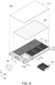
- FIG. 6 is an exploded perspective view of a battery pack 100 according to an embodiment of the present disclosure.
- the battery pack 100 may include a side frame 170 facing a pack unit body 140.
- the side frame 170 may include a partition wall frame 171 partitioning a space in which a plurality of pack unit bodies 140 are accommodated.
- the partition wall frame 171 may be disposed in a direction, parallel to an X-axis, and a direction, parallel to a Z-axis, and the plurality of pack unit bodies 140 may be accommodated in a space partitioned by the side frame 170 and the partition wall frame 171.
- the side frame 170 may have a first venting hole 170a in a region facing the partition wall frame 171.
- An inside of the side frame 170 may be provided have a hollow, and the hollow may be a second venting hole 170b.
- the second venting hole 170b may be a path by which gas is discharged outwardly of the battery pack.
- the partition wall frame 171 may have a third venting hole 171a in a region facing the pack unit body 140.
- the third venting hole 171a may be a path by which the gas, discharged from the pack unit body 140, is introduced.
- the gas, introduced into the third venting hole 171a may be introduced into the first venting hole 170a of the side frame 170 and may be then discharged outwardly through the second venting hole 170b. Matters regarding the number and diameter of the third venting hole 171a may be appropriately selected and applied depending on the number of battery cells 141, usage environments of the battery pack 100, specifications required for the battery pack 100, and the like, but exemplary embodiments are not limited thereto.
- a cover member 180 may be provided in upper portions of the pack unit body 140, the partition wall frame 171, and the side frame 170 in the positive Y-direction.
- the cover member 180 may be in contact with at least one of the side frame 170 and the partition wall frame 171, and may serve to block gas movement or gas propagation between the plurality of pack unit bodies 140.
- the cover member 180 may include a plurality of cover members provided to correspond to the pack unit bodies 140 in a one-to-one correspondence.
- exemplary embodiments are not limited thereto, and such a matter may be appropriately selected and applied depending on the usage environments of the battery pack, and the like.
- a first cooling plate 110 may be provided on an upper portion of the cover member 180 in a positive Y-direction.
- the cooling plate may be coupled to at least one of the cover member 180 and the side frame 170 to pressurize the cover member 180 and the pack unit body 140 in a negative Y-direction.
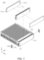
- FIG. 7 is a partially exploded perspective view of a battery pack 140 according to an embodiment of the present disclosure.
- the pack unit body 140 may include a plurality of battery cells 141, and at least one pad 145 may be provided between the plurality of battery cells 141.
- the pad 145 may be in contact with the battery cell 141 to perform cooling or to respond to a change in volume of the battery cell 141.
- a positive electrode tab 141a may be drawn out to one side of the battery cell 141, and a negative electrode tab 141b may be drawn out to the other side of the battery cell 141.
- a direction in which the positive electrode tab 141a and the negative electrode tab 141b are drawn out is not limited by the present disclosure.
- the plurality of battery cells 141 may be supported by a bus bar frame 142.
- the bus bar frame 142 may be provided to face the third venting hole (171a of FIG. 6 ) of the partition frame (171 of FIG. 6 ) .
- the bus bar frame 142 may be formed of an insulating material, and may include a bus bar member 143 to which the positive tab 141a and the negative tab 141b of the plurality of battery cells 141 are electrically connected.
- the bus bar member 143 may include a plurality of the bus bar members 143 provided on the bus bar frame 142.
- the bus bar member 143 may have a slot 143a into which the positive electrode tab 141a and the negative electrode tab 141b are inserted.
- the positive electrode tab 141a and the negative electrode tab 141b may be inserted into the slot 143a to be welded.
- the battery cells 141 disposed on front and rear surfaces of the pack unit body 140, may face an end plate 144, and the end plate 144 may be disposed in a region in which the bus bar frame 142 is absent. In an embodiment, the end plate 144 may be coupled to the bus bar frame 142.
- exemplary embodiments are not limited thereto, and such a matter may be appropriately selected and applied depending on required battery pack specifications, usage environments of the battery pack, and the like.
- the pack unit body 140 may be completed without using an additional member, to be advantageous for reducing weight of the entire battery pack.
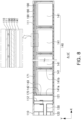
- FIG. 8 is a cross-sectional view taken along line A-A' of FIG. 6 .
- a battery pack may include a heat transfer material 190 interposed between the cover member 180 and the first cooling plate 110 and between the cover member 180 and the pack unit body 140.
- the heat transfer material 190 may be provided in the form of a pad to be in contact with the cover member 180, the first cooling plate 110, and the pack unit body 140.
- the heat transfer material 190 may be provided in the form of liquid or gel to be applied to the cover member 180, the first cooling plate 110, and the pack unit body 140.
- the heat transfer material 190 may be formed of a material including an insulating material and a material having high thermal conductivity.
- the heat transfer material 190 may include at least one of a thermal resin, a thermal grease, a thermal adhesive, an epoxy resin, and a heat dissipation pad.
- the heat transfer material 190 may include at least one of a thermal grease, a thermal conductive adhesive, an epoxy resin, and a heat dissipation pad.
- FIG. 9 is a cross-sectional view taken along line A-A' of FIG. 6 and illustrating a battery pack according to another embodiment of the present disclosure.
- the battery pack may include a heat transfer material 190 between a pack unit body 140 and a second cooling plate 120.
- the same matters as the above-described heat transfer material 190 may be applied to the heat transfer material 190 provided between the pack unit body 140 and the second cooling plate 120.
- the heat transfer material 190 may improve the assembling efficiency of the pack unit body 140, and may improve cooling efficiency of the battery cell 141 and the battery pack (100 of FIG. 6 ).
- the pack unit body 140 When the first cooling plate 110 and the second cooling plate 120 are respectively disposed above and below the pack unit body 140, the pack unit body 140 may be cooled above and below the back unit body 140. Therefore, cooling efficiency of the battery pack (100 of FIG. 6 ) may be improved.
- cooling efficiency of a battery cell may be improved.
- assembly efficiency and space utilization efficiency of a battery cell may be improved.
Landscapes
- Chemical & Material Sciences (AREA)
- Chemical Kinetics & Catalysis (AREA)
- Electrochemistry (AREA)
- General Chemical & Material Sciences (AREA)
- Engineering & Computer Science (AREA)
- Manufacturing & Machinery (AREA)
- Secondary Cells (AREA)
- Battery Mounting, Suspending (AREA)
Abstract
Description
- The present disclosure relates to a battery pack.
- A secondary battery is a battery capable of charging and discharging electricity, and has a wide application range, including to relatively small portable electronic devices, mid-sized to large-sized automobiles, and power storage devices.
- A secondary battery may be used as a secondary battery cell, and the secondary battery cell may have a configuration in which a stack body, including a positive electrode, a negative electrode, and a separator, is disposed in an exterior material and an electrolyte fills the inside of the exterior material. When a plurality of secondary battery cells are electrically connected to form a battery pack, capacity and an output amount of the battery pack may be increased.
- However, a plurality of secondary battery cells, arranged to be dense in a battery pack, may be overcharged and exposed to various events such as a high-temperature external environment at any time, so that the battery pack may have a risk of ignition or explosion.
- An aspect of the present disclosure is to improve cooling efficiency of a battery cell.
- Another aspect of the present disclosure is to improve assembly efficiency and space utilization efficiency of a battery cell.
- According to an aspect of the present disclosure, a battery pack includes: a first cooling plate including a first cooling path, along which a refrigerant is circulated, and a first inlet pipe connected to the first cooling path; a second cooling plate including a second cooling path, along which a refrigerant is circulated, and a second inlet pipe connected to the second cooling path and sealingly coupled to the first inlet pipe; a main supply pipe branching from the first inlet pipe or the second inlet pipe and supplying a refrigerant to the first inlet pipe and the second inlet pipe; and a pack unit body including at least one battery cell and disposed between the first cooling plate and the second cooling plate.
- The first cooling plate may further include a first outlet pipe connected to the first cooling path, and the second cooling plate may further include a second outlet pipe connected to the second cooling path and sealingly coupled to the first outlet pipe. The battery pack may further include a main outlet pipe branching from the first outlet pipe or the second outlet pipe and discharging a refrigerant, received from the first outlet pipe and the second outlet pipe, to the outside.
- The first inlet pipe may be coupled to the second inlet pipe in a coupling direction, parallel to a height direction of the battery cell.
- The main supply pipe and the main outlet pipe may allow a refrigerant to flow in a first flow direction, perpendicular to the coupling direction. The first inlet pipe, the first outlet pipe, the second inlet pipe, and the second outlet pipe may allow a refrigerant to flow in a second flow direction, parallel to the coupling direction.
- At least one of the first inlet pipe and the first outlet pipe may be provided such that an external diameter in a coupling portion to at least one of the second inlet pipe and the second outlet pipe is smaller than an internal diameter in a coupling portion to at least one of the second inlet pipe and the second outlet pipe. The first inlet pipe and the first outlet pipe may be fitted and coupled to the second inlet pipe and the second outlet pipe, respectively.
- The first inlet pipe and the first outlet pipe may be provided to have a loose fit tolerance or a medium fit tolerance to the second inlet pipe and the second outlet pipe, respectively.
- The battery pack may further include: a sealing member disposed in at least one of a position between an external surface of the first inlet pipe and an internal surface of the second inlet pipe and a position between an external surface of the first outlet pipe and an internal surface of the second outlet pipe.
- The battery pack may further include: a side frame facing the pack unit body; and a cover member disposed between the first cooling plate or the second cooling plate and the pack unit body to cover the pack unit body.
- The cover member may be disposed between the first cooling plate and the back unit body, and the battery pack may further include a heat transfer material disposed in at least one of a position between the cover member and the first cooling plate and a position between the cover member and the pack unit body.
- The heat transfer material may also be disposed between the pack unit body and the second cooling plate.
- At least one of the first inlet pipe, the first outlet pipe, the second inlet pipe, the second outlet pipe, the main supply pipe, and the main outlet pipe may be provided to be flexible.
- The side frame may have a first venting hole and a second venting hole connected to the outside, and the side frame may further include a partition wall frame having a third venting hole connected to the first venting hole and connected to the side frame such that the third venting hole faces the pack unit body.
-
-
FIG. 1 is a schematic cross-sectional view of a battery pack according to an embodiment of the present disclosure. -
FIG. 2 is a partially perspective view of a battery pack according to an embodiment of the present disclosure. -
FIG. 3 is an enlarged cross-sectional view of front end regions of a first cooling plate and a second cooling plate according to an embodiment of the present disclosure. -
FIG. 4 is a cross-sectional view of a first inlet pipe according to an embodiment of the present disclosure. -
FIG. 5 is a cross-sectional view of a second inlet pipe and a main supply pipe according to an embodiment of the present disclosure. -
FIG. 6 is an exploded perspective view of a battery pack according to an embodiment of the present disclosure. -
FIG. 7 is a partially exploded perspective view of a battery pack according to an embodiment of the present disclosure. -
FIG. 8 is a cross-sectional view taken along line A-A' ofFIG. 6 . -
FIG. 9 is a cross-sectional view taken along line A-A' ofFIG. 6 and illustrating a battery pack according to another embodiment of the present disclosure. -
FIG. 1 is a schematic cross-sectional view of a battery pack according to an embodiment of the present disclosure. - As illustrated in
FIG. 1 , a battery pack according to an embodiment may include afirst cooling plate 110 having afirst cooling path 111 therein, asecond cooling plate 120 having asecond cooling path 121 therein, and apack unit body 140 interposed between thefirst cooling plate 110 and thesecond cooling plate 120. - A refrigerant for cooling may be present in each of the
first cooling path 111 and thesecond cooling path 121. Water may be used as the refrigerant, but the type of the refrigerant is not limited by the present disclosure and may be appropriately selected and applied according to usage environments, capacity, and the like, of the battery pack. - The
first cooling plate 110, thesecond cooling plate 120, and thepack unit body 140 may be disposed in a direction, parallel to an X-axis, and may be stacked in a direction, parallel to a Y-axis. Each of thefirst cooling plate 110 and thesecond cooling plate 120 may be in contact with thepack unit body 140. - The
first cooling plate 110 may include afirst inlet pipe 112 connected to thefirst cooling path 111 and extending in a negative Y-direction. Thefirst inlet pipe 112 may be provided to allow the refrigerant to flow therein. The refrigerant may be introduced into thefirst cooling path 111 through thefirst inlet pipe 112. - The
second cooling plate 120 may include asecond inlet pipe 122 connected to thesecond cooling path 121 and extending in a positive Y-direction. Thesecond inlet pipe 122 may be provided to allow the refrigerant to flow therein. Thesecond inlet pipe 122 may be sealingly coupled to thefirst inlet pipe 112, and may be separated from thefirst inlet pipe 112, as necessary. The refrigerant may be introduced into thesecond cooling path 121 through thesecond inlet pipe 122. - The
first cooling path 111 and thefirst inlet pipe 112 may be sealingly coupled to each other, and thesecond cooling path 121 and thesecond inlet pipe 122 may be sealingly coupled to each other. A sealing component, such as an O-ring (not illustrated), may be used for sealingly coupling between thefirst cooling path 111 and thefirst inlet pipe 112 and between thesecond cooling path 121 and thesecond inlet pipe 122. Alternatively, a bracket for coupling (not illustrated) may be used as the sealing component, but exemplary embodiments are not limited thereto. - The structure, in which the
first cooling path 111 and thesecond cooling path 112 are respectively provided in thefirst cooling plate 110 and thesecond cooling plate 120, is not limited by the present disclosure. In consideration of cooling characteristics of the battery pack, thefirst cooling path 111 and thesecond cooling path 121 may be respectively provided, in an appropriate form, in thefirst cooling plate 110 and thesecond cooling plate 120. - A coupling direction, a direction in which the
first inlet pipe 112 and thesecond inlet pipe 122 are coupled to each other, may be perpendicular to thefirst cooling path 111. The coupling direction may be parallel to a Y-axis illustrated inFIG. 1 . The coupling direction may be parallel to a height direction of abattery cell 141. - A separation direction, a direction in which the
first inlet pipe 112 and thesecond inlet pipe 122 are separated from each other while being coupled to each other, may be perpendicular to thefirst cooling path 111. The separation direction may be parallel to a Y-axis illustrated inFIG. 1 . However, when the coupling direction is a negative Y-direction, the separation direction may be a positive Y-direction. - Accordingly, the coupling of the
first inlet pipe 112 and thesecond inlet pipe 122 may be completed by seating thepack unit body 140 on thesecond cooling plate 120 and covering thefirst cooling plate 110 with thepack unit body 140. This may contribute to improvement of assembly efficiency of the battery pack. - In an embodiment, the
main supply pipe 130 may branch from thesecond inlet pipe 122 in a direction, parallel to thesecond cooling path 121. Themain supply pipe 130 may be provided to allow the refrigerant to flow therein. A flow path, provided in themain supply pipe 130, may be disposed in a direction, parallel to thesecond cooling path 121. - In another embodiment, the
main supply pipe 130 may branch from thefirst inlet pipe 112. - When the
main supply pipe 130 has a structure branching from thefirst inlet pipe 112 or thesecond inlet pipe 122, a cooling structure of the battery pack may be completed only by coupling thefirst inlet pipe 112 and thesecond inlet pipe 122 to each other without an additional fastening component. Accordingly, components required to assemble the battery pack may significantly decrease in size, and manufacturing costs may be reduced. In addition, themain supply pipe 130 may be formed to be integrated with thefirst inlet pipe 112 or thesecond inlet pipe 122. - In addition, since the components required to assemble the battery pack significantly decrease in size, space efficiency of the battery pack may be improved.
- In addition, when the space efficiency of the battery pack is improved, the number of mounted
battery cells 141 may be increased as compared with the same volume. - In addition, unnecessary components may be excluded to reduce a weight of the battery pack.
- The
main supply pipe 130 may be connected to thepump 160. Thepump 160 may receive the refrigerant from a tank (not illustrated) in which the refrigerant is stored, and may supply the received refrigerant to themain supply pipe 130. In an embodiment, thepump 160 may be provided in a vehicle provided with a battery pack. However, exemplary embodiments are not limited thereto, and thepump 160 may be replaced with another power generation unit according to characteristics of a mechanical apparatus in which the battery pack is mounted. -
FIG. 2 is a partially perspective view of a battery pack according to an embodiment of the present disclosure. - As illustrated in
FIG. 2 , in an embodiment, thefirst cooling plate 110 may include afirst outlet pipe 113 connected to the first cooling path (111 ofFIG. 1 ) in a region, different from a region in which thefirst inlet pipe 112 is disposed. - In addition, the
second cooling plate 120 may include asecond outlet pipe 123 connected to the second cooling path (121 ofFIG. 1 ) in a region, different from a region in which thesecond inlet pipe 122 is disposed. Thesecond outlet pipe 123 may be sealingly coupled to thefirst outlet pipe 113. Thefirst outlet pipe 113 and thesecond outlet pipe 123 may be coupled to each other in a direction, parallel to a Y-axis, and may be separated from each other in a direction, parallel to the Y-axis. - The
first outlet pipe 113 may be a path by which the refrigerant of the first cooling path (111 ofFIG. 1 ) is discharged outwardly of thefirst cooling plate 110. - The
second outlet pipe 123 may be a path by which the refrigerant of the second cooling path (121 ofFIG. 1 ) is discharged outwardly of thesecond cooling plate 120. - The
main outlet pipe 150 may branch from thefirst outlet pipe 113 or thesecond outlet pipe 123. The battery pack according to an embodiment may include amain outlet pipe 150 branching from thesecond outlet pipe 123. However, themain outlet pipe 150 may branch from thefirst outlet pipe 113. When themain outlet pipe 150 has a structure branching from thefirst outlet pipe 113 or thesecond outlet pipe 123, a cooling structure of the battery pack may be completed only by coupling thefirst outlet pipe 113 and thesecond outlet pipe 123 to each other without an additional fastening component. Accordingly, components required to assemble the battery pack may significantly decrease in size, and manufacturing costs may be reduced. In addition, themain outlet pipe 150 may be formed to be integrated with thefirst outlet pipe 113 or thesecond outlet pipe 123. - The
main outlet pipe 150 may be provided to discharge the refrigerant, supplied from thefirst outlet pipe 113 and thesecond outlet pipe 123, to the outside of themain outlet pipe 150. A drain pipe (not illustrated) may be additionally connected to themain outlet pipe 150 to collect refrigerant, and the collected refrigerant may be supplied to an additional heat exchange device (not illustrated). Accordingly, the refrigerant may be circulated in the first cooling path (111 ofFIG. 1 ) and the second cooling path (121 ofFIG. 1 ), and the cooling efficiency of the battery cell (141 ofFIG. 1 ) may be improved. - In an embodiment, the
first inlet pipe 112, thesecond inlet pipe 122, thefirst outlet pipe 113, and thesecond outlet pipe 123 may be disposed in a front end region of thefirst cooling plate 110 or thesecond cooling plate 120. - In addition, in an embodiment, at least a portion of the
first inlet pipe 112, thesecond inlet pipe 122, thefirst outlet pipe 113, and thesecond outlet pipe 123 may be present on a lower surface or an upper surface of thecooling plate 110 or thesecond cooling plate 120. - In addition, in an embodiment, the
first inlet pipe 112, thesecond inlet pipe 122, thefirst outlet pipe 113 and thesecond outlet pipe 123 may be present outside a periphery of the back unit body (140 ofFIG. 1 ) on thefirst cooling plate 110 or thesecond cooling plate 120. Accordingly, a cooling structure, capable of significantly reducing a volume of the battery pack, may be implemented. -
FIG. 3 is an enlarged cross-sectional view of front end regions of thefirst cooling plate 110 and thesecond cooling plate 120, and is a cross-sectional view of thefirst inlet pipe 112 and thesecond inlet pipe 122. - A flow path, by which the refrigerant flows in the
main supply pipe 130, may be connected to a flow path, by which the refrigerant is introduced from thefirst inlet pipe 112, and a flow path by which the refrigerant flows in thesecond inlet pipe 122. - In the
main supply pipe 130, the refrigerant may flow in a first flow direction D1. The refrigerant, present in themain supply pipe 130, may be introduced into thefirst inlet pipe 112 and thesecond inlet pipe 122 by a pressure provided by the pump (160 ofFIG. 1 ). - In the
first inlet pipe 112 and thesecond inlet pipe 122, the refrigerant may flow in a second flow direction. The second flow direction may be parallel to a direction in which thefirst inlet pipe 112 is coupled to thesecond inlet pipe 122, and may be perpendicular to the first flow direction. The second flow direction may include a second upper flow direction D21, a flow direction in thefirst inlet pipe 112, and a second lower flow direction D22, a flow direction in thesecond inlet pipe 122. - In the
first inlet pipe 112, the refrigerant may flow in the second upper flow direction D21 to be supplied to thefirst cooling path 111. In thesecond inlet pipe 122, the refrigerant may flow in the second lower flow direction D22 to be supplied to thesecond cooling path 121. - In an embodiment, a diameter of the flow path, by which the refrigerant flows in the
first inlet pipe 112, and a diameter of the flow path, by which the refrigerant flows in thesecond inlet pipe 122, may be the same. Accordingly, the refrigerant may be uniformly distributed to thefirst cooling path 111 and thesecond cooling path 121. - The refrigerant, present in the
first cooling path 111, may be discharged through the first outlet pipe (113 ofFIG. 2 ). The refrigerant, present in thesecond cooling path 121, may be discharged through the second outlet pipe (123 of FIG.). The refrigerant of the first outlet pipe (113 ofFIG. 2 ) and the second outlet pipe (123 ofFIG. 2 ) meet in the main outlet pipe (150 ofFIG. 2 ), and may be finally discharged outwardly of thefirst cooling plate 110 and thesecond cooling plate 120 through the main outlet pipe (150 ofFIG. 2 ). - The
battery cell 141, disposed to be followed by thefirst inlet pipe 112 and thesecond inlet pipe 122 in an X-axis direction, may have a side surface surrounded by aside frame 170. Theside frame 170 may be in contact with thefirst cooling plate 110 and thesecond cooling plate 120 to protect the side surface of thebattery cell 141. - The
side frame 170 may partition a space, in which thebattery cell 141 is installed, and a space in which thefirst inlet pipe 112, thesecond inlet pipe 122, the first outlet pipe (113 ofFIG. 2 ), and the second outlet pipe (FIG. 2 of 123) are installed. Theside frame 170 may prevent the refrigerant from being introduced into thebattery cell 141 even when the refrigerant is discharged from the front end regions of thefirst cooling plate 110 and thesecond cooling plate 120. -
FIG. 4 is a cross-sectional view of thefirst inlet pipe 112 according to an embodiment of the present disclosure. - As illustrated in
FIG. 4 , thefirst inlet pipe 112 may have aninternal flow path 112c provided therein, and a refrigerant may flow in theinternal flow path 112c. - The
first inlet pipe 112 may have one side provided with afirst flange 112d protruding in a positive X-direction and a negative X-direction. Thefirst flange 112d may be in contact with the first cooling plate (110 ofFIG. 3 ), and components such as a bolt (not illustrated), and the like, may pass through thefirst flange 112d. In another embodiment, thefirst flange 112d may be welded to the first cooling plate (110 ofFIG. 3 ) . According to thefirst flange 112d, thefirst inlet pipe 112 may be easily coupled to the first cooling plate (110 ofFIG. 3 ) . - The
first inlet pipe 112 may have the other side provided with a plurality ofprojections 112a protruding in the positive X-direction and the negative X-direction. In thefirst inlet pipe 112, a region in which theprojection 112a is present may be a coupling portion to the second inlet pipe (122 ofFIG. 3 ) . In thefirst inlet pipe 112, anexternal diameter 112b of the region in which theprojection 112a is present may be smaller than an internal diameter (122a ofFIG. 5 ) of the second inlet pipe (122 ofFIG. 5 ). Accordingly, thefirst inlet pipe 112 may be fitted and coupled to the second inlet pipe (122 ofFIG. 3 ). The fitting coupling may contribute to improvement of assembling properties of thefirst inlet pipe 112 and the second inlet pipe (122 ofFIG. 3 ). - In an embodiment, a sealing
member 114 may be provided on an external surface of thefirst inlet pipe 112. The sealingmember 114 may be disposed between the external surface of thefirst inlet pipe 112 and an internal surface of the second inlet pipe (122 ofFIG. 3 ) to prevent the refrigerant from being discharged. The sealingmember 114 may be formed of a material including rubber, urethane, or the like. However, exemplary embodiments are not limited thereto, and the material of the sealingmember 114 may be appropriately changed and applied depending on the type of refrigerant, usage environments of the battery pack, specifications of the battery pack, and the like. The sealingmember 114 may also be disposed between an external surface of the first outlet pipe (113 ofFIG. 2 ) and an internal surface of the second outlet pipe (123 ofFIG. 2 ). -
FIG. 5 is a cross-sectional view of asecond inlet pipe 122 and amain supply pipe 130 according to an embodiment of the present disclosure. - As illustrated in
FIG. 5 , aninternal flow path 122b may be formed in thesecond inlet pipe 122 in a direction, parallel to a Y-axis, and a refrigerant may flow in theinternal flow path 122b. Aninternal diameter 122a in an uppermost portion of thesecond inlet pipe 122 in a positive Y-direction may be larger than an external diameter (112b ofFIG. 4 ) of the first inlet pipe (112 ofFIG. 4 ). - The
internal diameter 122a of thesecond inlet pipe 122 may be the same as aninternal diameter 122a of an uppermost portion of thesecond inlet pipe 122 in a positive Y-direction, from an uppermost portion of thesecond inlet pipe 122 in the positive Y-direction to a certain section in the negative Y-direction. The section, in which the internal diameter of thesecond inlet pipe 122 is the same as theinternal diameter 122a in the uppermost portion of thesecond inlet pipe 122 in the positive Y-direction, may be a coupling portion to the first inlet pipe (112 ofFIG. 4 ). - In an embodiment, the
internal diameter 122a in the uppermost portion of thesecond inlet pipe 122 in the positive Y-direction and the external diameter (112b ofFIG. 4 ) of the first inlet pipe (112 ofFIG. 4 ) may be provided to have a loose fit tolerance or a medium fit tolerance. Accordingly, fitting coupling between the first inlet pipe (112 ofFIG. 4 ) and thesecond inlet pipe 122 may be facilitated, and assembling properties of the first inlet pipe (112 ofFIG. 4 ) and thesecond inlet pipe 122 may be improved. What has been described above may be equally applied to coupling between the first outlet pipe (113 ofFIG. 2 ) and the second outlet pipe (123 ofFIG. 2 ). - A lower portion of the
second inlet pipe 122 in a negative Y-direction may be provided with asecond flange 122c protruding in a radial direction of thesecond inlet pipe 122. Thesecond flange 122c may be in contact with the second cooling plate (120 ofFIG. 3 ), and components such as a bolt (not illustrated), and the like, may pass through thesecond flange 122c. In another embodiment, thesecond flange 122c may be welded to the second cooling plate (120 ofFIG. 3 ). According to thesecond flange 122c, thesecond inlet pipe 122 may be easily coupled to the second cooling plate (120 ofFIG. 3 ). - The
main supply pipe 130 may branch from thesecond inlet pipe 122. Aninternal flow path 131 may be formed in themain supply pipe 130 in a direction, parallel to the X-axis, and may be connected to aninternal flow path 122b of thesecond inlet pipe 122. Themain supply pipe 130 may be provided to be integrated with thesecond inlet pipe 122, or may be coupled to thesecond inlet pipe 122 by welding, or the like. However, exemplary embodiments are not limited thereto. - In an embodiment, at least a portion of an external periphery of the
main supply pipe 130 may have a shape protruding in a radial direction thereof, which may contribute to easy coupling between themain supply pipe 130 and a pipe (not illustrated) or a hose (not illustrated) extending from the pump (160 ofFIG. 1 ). - In an embodiment, at least one of the
first inlet pipe 112, the second inlet pipe (122 ofFIG. 2 ), the first outlet pipe (113 ofFIG. 2 ), the second outlet pipe (123 ofFIG. 2 ), the main supply pipe (130 ofFIG. 2 ), and the main outlet pipe (150 ofFIG. 2 ) may be provided to be flexible. - In an embodiment, at least one of the
first inlet pipe 112, the second inlet pipe (122 ofFIG. 2 ), the first outlet pipe (113 ofFIG. 2 ), the second outlet pipe (123 ofFIG. 2 ), the main supply pipe (130 ofFIG. 2 ), and the main outlet pipe (150 ofFIG. 2 ) may be formed of a material including a flexible material. - In an embodiment, at least one of the
first inlet pipe 112, the second inlet pipe (122 ofFIG. 2 ), the first outlet pipe (113 ofFIG. 2 ), the second outlet pipe (123 ofFIG. 2 ), the main supply pipe (130 ofFIG. 2 ), and the main outlet pipe (150 ofFIG. 2 ) may be provided with a corrugated external periphery to be subject to at least one of extension, contraction, and bending deformation. - Accordingly, it may contribute to improvement of assembling efficiency of the battery pack and improvement of space utilization efficiency.
-
FIG. 6 is an exploded perspective view of abattery pack 100 according to an embodiment of the present disclosure. - As illustrated of
FIG. 6 , thebattery pack 100 according to an embodiment may include aside frame 170 facing apack unit body 140. Theside frame 170 may include apartition wall frame 171 partitioning a space in which a plurality ofpack unit bodies 140 are accommodated. Thepartition wall frame 171 may be disposed in a direction, parallel to an X-axis, and a direction, parallel to a Z-axis, and the plurality ofpack unit bodies 140 may be accommodated in a space partitioned by theside frame 170 and thepartition wall frame 171. - The
side frame 170 may have afirst venting hole 170a in a region facing thepartition wall frame 171. An inside of theside frame 170 may be provided have a hollow, and the hollow may be asecond venting hole 170b. Thesecond venting hole 170b may be a path by which gas is discharged outwardly of the battery pack. - The
partition wall frame 171 may have athird venting hole 171a in a region facing thepack unit body 140. Thethird venting hole 171a may be a path by which the gas, discharged from thepack unit body 140, is introduced. The gas, introduced into thethird venting hole 171a, may be introduced into thefirst venting hole 170a of theside frame 170 and may be then discharged outwardly through thesecond venting hole 170b. Matters regarding the number and diameter of thethird venting hole 171a may be appropriately selected and applied depending on the number ofbattery cells 141, usage environments of thebattery pack 100, specifications required for thebattery pack 100, and the like, but exemplary embodiments are not limited thereto. - In an embodiment, a
cover member 180 may be provided in upper portions of thepack unit body 140, thepartition wall frame 171, and theside frame 170 in the positive Y-direction. Thecover member 180 may be in contact with at least one of theside frame 170 and thepartition wall frame 171, and may serve to block gas movement or gas propagation between the plurality ofpack unit bodies 140. - In an embodiment, the
cover member 180 may include a plurality of cover members provided to correspond to thepack unit bodies 140 in a one-to-one correspondence. However, exemplary embodiments are not limited thereto, and such a matter may be appropriately selected and applied depending on the usage environments of the battery pack, and the like. - In an embodiment, a
first cooling plate 110 may be provided on an upper portion of thecover member 180 in a positive Y-direction. The cooling plate may be coupled to at least one of thecover member 180 and theside frame 170 to pressurize thecover member 180 and thepack unit body 140 in a negative Y-direction. -
FIG. 7 is a partially exploded perspective view of abattery pack 140 according to an embodiment of the present disclosure. - As illustrated of
FIG. 7 , thepack unit body 140 may include a plurality ofbattery cells 141, and at least onepad 145 may be provided between the plurality ofbattery cells 141. Thepad 145 may be in contact with thebattery cell 141 to perform cooling or to respond to a change in volume of thebattery cell 141. - A
positive electrode tab 141a may be drawn out to one side of thebattery cell 141, and anegative electrode tab 141b may be drawn out to the other side of thebattery cell 141. However, a direction in which thepositive electrode tab 141a and thenegative electrode tab 141b are drawn out is not limited by the present disclosure. - The plurality of
battery cells 141 may be supported by abus bar frame 142. Thebus bar frame 142 may be provided to face the third venting hole (171a ofFIG. 6 ) of the partition frame (171 ofFIG. 6 ) . In addition, thebus bar frame 142 may be formed of an insulating material, and may include abus bar member 143 to which thepositive tab 141a and thenegative tab 141b of the plurality ofbattery cells 141 are electrically connected. Thebus bar member 143 may include a plurality of thebus bar members 143 provided on thebus bar frame 142. - The
bus bar member 143 may have aslot 143a into which thepositive electrode tab 141a and thenegative electrode tab 141b are inserted. Thepositive electrode tab 141a and thenegative electrode tab 141b may be inserted into theslot 143a to be welded. - The
battery cells 141, disposed on front and rear surfaces of thepack unit body 140, may face anend plate 144, and theend plate 144 may be disposed in a region in which thebus bar frame 142 is absent. In an embodiment, theend plate 144 may be coupled to thebus bar frame 142. However, exemplary embodiments are not limited thereto, and such a matter may be appropriately selected and applied depending on required battery pack specifications, usage environments of the battery pack, and the like. - As described above, when the plurality of
battery cells 141 are supported by thebus bar frame 142 and theend plate 144, thepack unit body 140 may be completed without using an additional member, to be advantageous for reducing weight of the entire battery pack. -
FIG. 8 is a cross-sectional view taken along line A-A' ofFIG. 6 . - As illustrated of
FIG. 8 , a battery pack according to an embodiment may include aheat transfer material 190 interposed between thecover member 180 and thefirst cooling plate 110 and between thecover member 180 and thepack unit body 140. Theheat transfer material 190 may be provided in the form of a pad to be in contact with thecover member 180, thefirst cooling plate 110, and thepack unit body 140. Alternatively, theheat transfer material 190 may be provided in the form of liquid or gel to be applied to thecover member 180, thefirst cooling plate 110, and thepack unit body 140. - In an embodiment, the
heat transfer material 190 may be formed of a material including an insulating material and a material having high thermal conductivity. - In addition, in an embodiment, the
heat transfer material 190 may include at least one of a thermal resin, a thermal grease, a thermal adhesive, an epoxy resin, and a heat dissipation pad. - When the
first cooling plate 110 is disposed on thebattery cell 141, theheat transfer material 190 may include at least one of a thermal grease, a thermal conductive adhesive, an epoxy resin, and a heat dissipation pad. -
FIG. 9 is a cross-sectional view taken along line A-A' ofFIG. 6 and illustrating a battery pack according to another embodiment of the present disclosure. - As illustrated of
FIG. 9 , the battery pack according to another embodiment may include aheat transfer material 190 between apack unit body 140 and asecond cooling plate 120. The same matters as the above-describedheat transfer material 190 may be applied to theheat transfer material 190 provided between thepack unit body 140 and thesecond cooling plate 120. - The
heat transfer material 190 may improve the assembling efficiency of thepack unit body 140, and may improve cooling efficiency of thebattery cell 141 and the battery pack (100 ofFIG. 6 ). - When the
first cooling plate 110 and thesecond cooling plate 120 are respectively disposed above and below thepack unit body 140, thepack unit body 140 may be cooled above and below theback unit body 140. Therefore, cooling efficiency of the battery pack (100 ofFIG. 6 ) may be improved. - As described above, cooling efficiency of a battery cell may be improved.
- In addition, assembly efficiency and space utilization efficiency of a battery cell may be improved.
Claims (12)
- A battery pack comprising:a first cooling plate including a first cooling path, along which a refrigerant is circulated, and a first inlet pipe connected to the first cooling path;a second cooling plate including a second cooling path, along which a refrigerant is circulated, and a second inlet pipe connected to the second cooling path and sealingly coupled to the first inlet pipe;a main supply pipe branching from the first inlet pipe or the second inlet pipe and supplying a refrigerant to the first inlet pipe and the second inlet pipe; anda pack unit body including at least one battery cell and disposed between the first cooling plate and the second cooling plate.
- The battery pack of claim 1, wherein:the first cooling plate further includes a first outlet pipe connected to the first cooling path;the second cooling plate further includes a second outlet pipe connected to the second cooling path and sealingly coupled to the first outlet pipe; andwherein the battery pack further includes a main outlet pipe branching from the first outlet pipe or the second outlet pipe and discharging a refrigerant, received from the first outlet pipe and the second outlet pipe, to the outside.
- The battery pack of claim 1 or 2, wherein:
the first inlet pipe is coupled to the second inlet pipe in a coupling direction, parallel to a height direction of the battery cell. - The battery pack of claim 2 or 3, wherein:the main supply pipe and the main outlet pipe allow a refrigerant to flow in a first flow direction, perpendicular to the coupling direction; andthe first inlet pipe, the first outlet pipe, the second inlet pipe, and the second outlet pipe allow a refrigerant to flow in a second flow direction, parallel to the coupling direction.
- The battery pack of anyone of claims 2 to 4, wherein:at least one of the first inlet pipe and the first outlet pipe is provided such that an external diameter in a coupling portion to at least one of the second inlet pipe and the second outlet pipe is smaller than an internal diameter in a coupling portion to at least one of the second inlet pipe and the second outlet pipe; andthe first inlet pipe and the first outlet pipe are fitted and coupled to the second inlet pipe and the second outlet pipe, respectively.
- The battery pack of anyone of claims 2 to 5, wherein:
the first inlet pipe and the first outlet pipe are provided to have a loose fit tolerance or a medium fit tolerance to the second inlet pipe and the second outlet pipe, respectively. - The battery pack of anyone of claims 2 to 6, further comprising:
a sealing member disposed in at least one of a position between an external surface of the first inlet pipe and an internal surface of the second inlet pipe and a position between an external surface of the first outlet pipe and an internal surface of the second outlet pipe. - The battery pack of any one of claims 1 to 7, further comprising:a side frame facing the pack unit body; anda cover member disposed between the first cooling plate or the second cooling plate and the pack unit body to cover the pack unit body.
- The battery pack of claim 8, wherein:the cover member is disposed between the first cooling plate and the back unit body; andwherein the battery pack further includes a heat transfer material disposed in at least one of a position between the cover member and the first cooling plate and a position between the cover member and the pack unit body.
- The battery pack of claim 9, wherein:
the heat transfer material is further disposed between the pack unit body and the second cooling plate. - The battery pack of any one of claims 2 to 10, wherein:
at least one of the first inlet pipe, the first outlet pipe, the second inlet pipe, the second outlet pipe, the main supply pipe, and the main outlet pipe is provided to be flexible. - The battery pack of anyone of claims 8 to 11, wherein:the side frame has a first venting hole and a second venting hole connected to the outside; andthe side frame further includes a partition wall frame having a third venting hole connected to the first venting hole and connected to the side frame such that the third venting hole faces the pack unit body.
Priority Applications (1)
| Application Number | Priority Date | Filing Date | Title |
|---|---|---|---|
| EP26154731.9A EP4712230A3 (en) | 2021-09-30 | 2022-09-27 | Battery pack |
Applications Claiming Priority (1)
| Application Number | Priority Date | Filing Date | Title |
|---|---|---|---|
| KR1020210129490A KR20230046465A (en) | 2021-09-30 | 2021-09-30 | Battery pack |
Related Child Applications (2)
| Application Number | Title | Priority Date | Filing Date |
|---|---|---|---|
| EP26154731.9A Division EP4712230A3 (en) | 2021-09-30 | 2022-09-27 | Battery pack |
| EP26154731.9A Division-Into EP4712230A3 (en) | 2021-09-30 | 2022-09-27 | Battery pack |
Publications (2)
| Publication Number | Publication Date |
|---|---|
| EP4160789A1 true EP4160789A1 (en) | 2023-04-05 |
| EP4160789B1 EP4160789B1 (en) | 2026-03-04 |
Family
ID=83505687
Family Applications (2)
| Application Number | Title | Priority Date | Filing Date |
|---|---|---|---|
| EP22198099.8A Active EP4160789B1 (en) | 2021-09-30 | 2022-09-27 | Battery pack |
| EP26154731.9A Pending EP4712230A3 (en) | 2021-09-30 | 2022-09-27 | Battery pack |
Family Applications After (1)
| Application Number | Title | Priority Date | Filing Date |
|---|---|---|---|
| EP26154731.9A Pending EP4712230A3 (en) | 2021-09-30 | 2022-09-27 | Battery pack |
Country Status (4)
| Country | Link |
|---|---|
| US (1) | US12586838B2 (en) |
| EP (2) | EP4160789B1 (en) |
| KR (1) | KR20230046465A (en) |
| CN (1) | CN115911641A (en) |
Families Citing this family (6)
| Publication number | Priority date | Publication date | Assignee | Title |
|---|---|---|---|---|
| US20260051555A1 (en) * | 2023-06-16 | 2026-02-19 | Lg Energy Solution, Ltd. | Battery Pack and Vehicle Including Same |
| KR20250009038A (en) * | 2023-07-10 | 2025-01-17 | 주식회사 엘지에너지솔루션 | Cooling device and battery pack including the same |
| KR20250120061A (en) * | 2024-02-01 | 2025-08-08 | 주식회사 엘지에너지솔루션 | Battery pack |
| KR20260023771A (en) * | 2024-08-12 | 2026-02-20 | 현대모비스 주식회사 | Batery cell assembly |
| KR20260031299A (en) * | 2024-08-28 | 2026-03-09 | 주식회사 엘지에너지솔루션 | Battery pack and vehicle including the same |
| WO2026084283A1 (en) * | 2024-10-14 | 2026-04-23 | 주식회사 엘지에너지솔루션 | Battery device |
Citations (2)
| Publication number | Priority date | Publication date | Assignee | Title |
|---|---|---|---|---|
| DE102016001145A1 (en) * | 2016-02-02 | 2017-08-03 | Audi Ag | Motor vehicle battery |
| EP3528336A1 (en) * | 2016-10-13 | 2019-08-21 | Samsung SDI Co., Ltd | Battery module |
Family Cites Families (13)
| Publication number | Priority date | Publication date | Assignee | Title |
|---|---|---|---|---|
| JP2013012441A (en) | 2011-06-30 | 2013-01-17 | Sanyo Electric Co Ltd | Electric power source device and vehicle including the same |
| EP2608309A1 (en) | 2011-12-21 | 2013-06-26 | Fortu Intellectual Property AG | Battery module with battery module housing and battery cells |
| US20130209857A1 (en) * | 2012-02-15 | 2013-08-15 | GM Global Technology Operations LLC | Battery tray design |
| US10454147B2 (en) * | 2015-11-19 | 2019-10-22 | Intramicron, Inc. | Battery pack for energy storage devices |
| KR102034495B1 (en) | 2017-07-04 | 2019-10-21 | 에스케이이노베이션 주식회사 | Battery Comprising Cooling Member |
| CN110190211B (en) | 2018-12-29 | 2020-03-31 | 比亚迪股份有限公司 | Battery tray, power battery package and vehicle |
| KR102533382B1 (en) * | 2019-01-09 | 2023-05-19 | 한온시스템 주식회사 | Thermal management system |
| KR102828349B1 (en) * | 2019-09-09 | 2025-07-03 | 삼성에스디아이 주식회사 | Battery pack |
| US11588199B2 (en) * | 2020-03-10 | 2023-02-21 | Karma Automotive Llc | Vehicle battery system |
| DE102022133232A1 (en) * | 2022-12-14 | 2024-06-20 | Audi Aktiengesellschaft | Cooling arrangement for cooling a battery unit and battery module on both sides for a motor vehicle |
| US20240204289A1 (en) * | 2022-12-15 | 2024-06-20 | Sk On Co., Ltd. | Battery assembly and battery pack including battery assembly |
| KR20240093000A (en) * | 2022-12-15 | 2024-06-24 | 에스케이온 주식회사 | Battery Device |
| US20240237314A1 (en) * | 2023-01-11 | 2024-07-11 | Ford Global Technologies, Llc | Systems and methods for cooling of an electric energy storage device |
-
2021
- 2021-09-30 KR KR1020210129490A patent/KR20230046465A/en active Pending
-
2022
- 2022-09-27 EP EP22198099.8A patent/EP4160789B1/en active Active
- 2022-09-27 EP EP26154731.9A patent/EP4712230A3/en active Pending
- 2022-09-28 CN CN202211191242.4A patent/CN115911641A/en active Pending
- 2022-09-30 US US17/958,144 patent/US12586838B2/en active Active
Patent Citations (2)
| Publication number | Priority date | Publication date | Assignee | Title |
|---|---|---|---|---|
| DE102016001145A1 (en) * | 2016-02-02 | 2017-08-03 | Audi Ag | Motor vehicle battery |
| EP3528336A1 (en) * | 2016-10-13 | 2019-08-21 | Samsung SDI Co., Ltd | Battery module |
Also Published As
| Publication number | Publication date |
|---|---|
| EP4712230A2 (en) | 2026-03-18 |
| CN115911641A (en) | 2023-04-04 |
| EP4160789B1 (en) | 2026-03-04 |
| US12586838B2 (en) | 2026-03-24 |
| US20230095960A1 (en) | 2023-03-30 |
| KR20230046465A (en) | 2023-04-06 |
| EP4712230A3 (en) | 2026-05-06 |
Similar Documents
| Publication | Publication Date | Title |
|---|---|---|
| EP4160789A1 (en) | Battery pack | |
| CN114144927B (en) | A battery pack that combines battery modules and rigid beams and is assembled in reverse | |
| JP7625653B2 (en) | Top-cooled battery pack | |
| KR20220098706A (en) | Battery Pack comprising a Frame Profile with Integral Coolant Circuit Elements | |
| EP1984966B1 (en) | Medium and large size battery module of vertical stacking structure | |
| US11721856B2 (en) | Battery pack for a vehicle | |
| JP2019525397A (en) | Battery submodule carrier, battery submodule, battery system and automobile | |
| JP7353503B2 (en) | Battery packs and devices containing them | |
| JP7154652B2 (en) | Battery packs and devices containing them | |
| CN116472637A (en) | Battery pack and device including the battery pack | |
| EP4266464B1 (en) | Battery, power consumption device, and method and device for producing battery | |
| EP4210154A1 (en) | Battery pack and device comprising same | |
| JP7538888B2 (en) | Battery pack and vehicle including such a battery pack | |
| CN116783761A (en) | Battery module and battery pack including the battery module | |
| CN120033379A (en) | Battery device and power device | |
| CN120016065B (en) | Battery device and electricity utilization device | |
| CN120016045B (en) | Battery devices and electrical appliances | |
| KR20230052212A (en) | Battery pack and vehicle comprising the battery pack | |
| KR20250172451A (en) | Pressure relief assembly, battery module, battery pack, and powered device | |
| CN120033384A (en) | Battery device and power device | |
| EP3772122B1 (en) | Battery module with a multifunctional end-plate | |
| EP3637537B1 (en) | Bypass tube for a cooling circuit of a vehicle battery pack | |
| CN114556668A (en) | Battery module and method for manufacturing battery module | |
| JP2022553034A (en) | Battery packs and devices containing them | |
| CN118633201A (en) | Battery Pack |
Legal Events
| Date | Code | Title | Description |
|---|---|---|---|
| PUAI | Public reference made under article 153(3) epc to a published international application that has entered the european phase |
Free format text: ORIGINAL CODE: 0009012 |
|
| STAA | Information on the status of an ep patent application or granted ep patent |
Free format text: STATUS: THE APPLICATION HAS BEEN PUBLISHED |
|
| AK | Designated contracting states |
Kind code of ref document: A1 Designated state(s): AL AT BE BG CH CY CZ DE DK EE ES FI FR GB GR HR HU IE IS IT LI LT LU LV MC MK MT NL NO PL PT RO RS SE SI SK SM TR |
|
| P01 | Opt-out of the competence of the unified patent court (upc) registered |
Effective date: 20230602 |
|
| STAA | Information on the status of an ep patent application or granted ep patent |
Free format text: STATUS: REQUEST FOR EXAMINATION WAS MADE |
|
| 17P | Request for examination filed |
Effective date: 20230927 |
|
| RBV | Designated contracting states (corrected) |
Designated state(s): AL AT BE BG CH CY CZ DE DK EE ES FI FR GB GR HR HU IE IS IT LI LT LU LV MC MK MT NL NO PL PT RO RS SE SI SK SM TR |
|
| GRAP | Despatch of communication of intention to grant a patent |
Free format text: ORIGINAL CODE: EPIDOSNIGR1 |
|
| STAA | Information on the status of an ep patent application or granted ep patent |
Free format text: STATUS: GRANT OF PATENT IS INTENDED |
|
| INTG | Intention to grant announced |
Effective date: 20250930 |
|
| RIC1 | Information provided on ipc code assigned before grant |
Ipc: H01M 10/6556 20140101AFI20250922BHEP Ipc: H01M 10/6568 20140101ALI20250922BHEP Ipc: H01M 10/613 20140101ALI20250922BHEP Ipc: H01M 10/625 20140101ALI20250922BHEP Ipc: H01M 50/204 20210101ALI20250922BHEP |
|
| GRAS | Grant fee paid |
Free format text: ORIGINAL CODE: EPIDOSNIGR3 |
|
| GRAA | (expected) grant |
Free format text: ORIGINAL CODE: 0009210 |
|
| STAA | Information on the status of an ep patent application or granted ep patent |
Free format text: STATUS: THE PATENT HAS BEEN GRANTED |
|
| AK | Designated contracting states |
Kind code of ref document: B1 Designated state(s): AL AT BE BG CH CY CZ DE DK EE ES FI FR GB GR HR HU IE IS IT LI LT LU LV MC MK MT NL NO PL PT RO RS SE SI SK SM TR |
|
| REG | Reference to a national code |
Ref country code: CH Ref legal event code: F10 Free format text: ST27 STATUS EVENT CODE: U-0-0-F10-F00 (AS PROVIDED BY THE NATIONAL OFFICE) Effective date: 20260304 Ref country code: GB Ref legal event code: FG4D |
|
| REG | Reference to a national code |
Ref country code: IE Ref legal event code: FG4D |
|
| REG | Reference to a national code |
Ref country code: DE Ref legal event code: R096 Ref document number: 602022031515 Country of ref document: DE |