EP4160783A1 - Battery pack - Google Patents
Battery pack Download PDFInfo
- Publication number
- EP4160783A1 EP4160783A1 EP22198091.5A EP22198091A EP4160783A1 EP 4160783 A1 EP4160783 A1 EP 4160783A1 EP 22198091 A EP22198091 A EP 22198091A EP 4160783 A1 EP4160783 A1 EP 4160783A1
- Authority
- EP
- European Patent Office
- Prior art keywords
- connecting member
- partition wall
- battery pack
- accommodated
- cell stack
- Prior art date
- Legal status (The legal status is an assumption and is not a legal conclusion. Google has not performed a legal analysis and makes no representation as to the accuracy of the status listed.)
- Granted
Links
Images



Classifications
-
- H—ELECTRICITY
- H01—ELECTRIC ELEMENTS
- H01M—PROCESSES OR MEANS, e.g. BATTERIES, FOR THE DIRECT CONVERSION OF CHEMICAL ENERGY INTO ELECTRICAL ENERGY
- H01M10/00—Secondary cells; Manufacture thereof
- H01M10/42—Methods or arrangements for servicing or maintenance of secondary cells or secondary half-cells
- H01M10/425—Structural combination with electronic components, e.g. electronic circuits integrated to the outside of the casing
-
- H—ELECTRICITY
- H01—ELECTRIC ELEMENTS
- H01M—PROCESSES OR MEANS, e.g. BATTERIES, FOR THE DIRECT CONVERSION OF CHEMICAL ENERGY INTO ELECTRICAL ENERGY
- H01M50/00—Constructional details or processes of manufacture of the non-active parts of electrochemical cells other than fuel cells, e.g. hybrid cells
- H01M50/20—Mountings; Secondary casings or frames; Racks, modules or packs; Suspension devices; Shock absorbers; Transport or carrying devices; Holders
- H01M50/289—Mountings; Secondary casings or frames; Racks, modules or packs; Suspension devices; Shock absorbers; Transport or carrying devices; Holders characterised by spacing elements or positioning means within frames, racks or packs
- H01M50/291—Mountings; Secondary casings or frames; Racks, modules or packs; Suspension devices; Shock absorbers; Transport or carrying devices; Holders characterised by spacing elements or positioning means within frames, racks or packs characterised by their shape
-
- H—ELECTRICITY
- H01—ELECTRIC ELEMENTS
- H01M—PROCESSES OR MEANS, e.g. BATTERIES, FOR THE DIRECT CONVERSION OF CHEMICAL ENERGY INTO ELECTRICAL ENERGY
- H01M50/00—Constructional details or processes of manufacture of the non-active parts of electrochemical cells other than fuel cells, e.g. hybrid cells
- H01M50/20—Mountings; Secondary casings or frames; Racks, modules or packs; Suspension devices; Shock absorbers; Transport or carrying devices; Holders
- H01M50/204—Racks, modules or packs for multiple batteries or multiple cells
-
- H—ELECTRICITY
- H01—ELECTRIC ELEMENTS
- H01M—PROCESSES OR MEANS, e.g. BATTERIES, FOR THE DIRECT CONVERSION OF CHEMICAL ENERGY INTO ELECTRICAL ENERGY
- H01M10/00—Secondary cells; Manufacture thereof
- H01M10/42—Methods or arrangements for servicing or maintenance of secondary cells or secondary half-cells
- H01M10/48—Accumulators combined with arrangements for measuring, testing or indicating the condition of cells, e.g. the level or density of the electrolyte
- H01M10/482—Accumulators combined with arrangements for measuring, testing or indicating the condition of cells, e.g. the level or density of the electrolyte for several batteries or cells simultaneously or sequentially
-
- H—ELECTRICITY
- H01—ELECTRIC ELEMENTS
- H01M—PROCESSES OR MEANS, e.g. BATTERIES, FOR THE DIRECT CONVERSION OF CHEMICAL ENERGY INTO ELECTRICAL ENERGY
- H01M50/00—Constructional details or processes of manufacture of the non-active parts of electrochemical cells other than fuel cells, e.g. hybrid cells
- H01M50/20—Mountings; Secondary casings or frames; Racks, modules or packs; Suspension devices; Shock absorbers; Transport or carrying devices; Holders
-
- H—ELECTRICITY
- H01—ELECTRIC ELEMENTS
- H01M—PROCESSES OR MEANS, e.g. BATTERIES, FOR THE DIRECT CONVERSION OF CHEMICAL ENERGY INTO ELECTRICAL ENERGY
- H01M50/00—Constructional details or processes of manufacture of the non-active parts of electrochemical cells other than fuel cells, e.g. hybrid cells
- H01M50/20—Mountings; Secondary casings or frames; Racks, modules or packs; Suspension devices; Shock absorbers; Transport or carrying devices; Holders
- H01M50/204—Racks, modules or packs for multiple batteries or multiple cells
- H01M50/207—Racks, modules or packs for multiple batteries or multiple cells characterised by their shape
-
- H—ELECTRICITY
- H01—ELECTRIC ELEMENTS
- H01M—PROCESSES OR MEANS, e.g. BATTERIES, FOR THE DIRECT CONVERSION OF CHEMICAL ENERGY INTO ELECTRICAL ENERGY
- H01M50/00—Constructional details or processes of manufacture of the non-active parts of electrochemical cells other than fuel cells, e.g. hybrid cells
- H01M50/20—Mountings; Secondary casings or frames; Racks, modules or packs; Suspension devices; Shock absorbers; Transport or carrying devices; Holders
- H01M50/249—Mountings; Secondary casings or frames; Racks, modules or packs; Suspension devices; Shock absorbers; Transport or carrying devices; Holders specially adapted for aircraft or vehicles, e.g. cars or trains
-
- H—ELECTRICITY
- H01—ELECTRIC ELEMENTS
- H01M—PROCESSES OR MEANS, e.g. BATTERIES, FOR THE DIRECT CONVERSION OF CHEMICAL ENERGY INTO ELECTRICAL ENERGY
- H01M50/00—Constructional details or processes of manufacture of the non-active parts of electrochemical cells other than fuel cells, e.g. hybrid cells
- H01M50/20—Mountings; Secondary casings or frames; Racks, modules or packs; Suspension devices; Shock absorbers; Transport or carrying devices; Holders
- H01M50/271—Lids or covers for the racks or secondary casings
-
- H—ELECTRICITY
- H01—ELECTRIC ELEMENTS
- H01M—PROCESSES OR MEANS, e.g. BATTERIES, FOR THE DIRECT CONVERSION OF CHEMICAL ENERGY INTO ELECTRICAL ENERGY
- H01M50/00—Constructional details or processes of manufacture of the non-active parts of electrochemical cells other than fuel cells, e.g. hybrid cells
- H01M50/20—Mountings; Secondary casings or frames; Racks, modules or packs; Suspension devices; Shock absorbers; Transport or carrying devices; Holders
- H01M50/296—Mountings; Secondary casings or frames; Racks, modules or packs; Suspension devices; Shock absorbers; Transport or carrying devices; Holders characterised by terminals of battery packs
-
- H—ELECTRICITY
- H01—ELECTRIC ELEMENTS
- H01M—PROCESSES OR MEANS, e.g. BATTERIES, FOR THE DIRECT CONVERSION OF CHEMICAL ENERGY INTO ELECTRICAL ENERGY
- H01M50/00—Constructional details or processes of manufacture of the non-active parts of electrochemical cells other than fuel cells, e.g. hybrid cells
- H01M50/20—Mountings; Secondary casings or frames; Racks, modules or packs; Suspension devices; Shock absorbers; Transport or carrying devices; Holders
- H01M50/298—Mountings; Secondary casings or frames; Racks, modules or packs; Suspension devices; Shock absorbers; Transport or carrying devices; Holders characterised by the wiring of battery packs
-
- H—ELECTRICITY
- H01—ELECTRIC ELEMENTS
- H01M—PROCESSES OR MEANS, e.g. BATTERIES, FOR THE DIRECT CONVERSION OF CHEMICAL ENERGY INTO ELECTRICAL ENERGY
- H01M50/00—Constructional details or processes of manufacture of the non-active parts of electrochemical cells other than fuel cells, e.g. hybrid cells
- H01M50/50—Current conducting connections for cells or batteries
- H01M50/502—Interconnectors for connecting terminals of adjacent batteries; Interconnectors for connecting cells outside a battery casing
-
- H—ELECTRICITY
- H01—ELECTRIC ELEMENTS
- H01M—PROCESSES OR MEANS, e.g. BATTERIES, FOR THE DIRECT CONVERSION OF CHEMICAL ENERGY INTO ELECTRICAL ENERGY
- H01M50/00—Constructional details or processes of manufacture of the non-active parts of electrochemical cells other than fuel cells, e.g. hybrid cells
- H01M50/50—Current conducting connections for cells or batteries
- H01M50/502—Interconnectors for connecting terminals of adjacent batteries; Interconnectors for connecting cells outside a battery casing
- H01M50/503—Interconnectors for connecting terminals of adjacent batteries; Interconnectors for connecting cells outside a battery casing characterised by the shape of the interconnectors
-
- H—ELECTRICITY
- H01—ELECTRIC ELEMENTS
- H01M—PROCESSES OR MEANS, e.g. BATTERIES, FOR THE DIRECT CONVERSION OF CHEMICAL ENERGY INTO ELECTRICAL ENERGY
- H01M50/00—Constructional details or processes of manufacture of the non-active parts of electrochemical cells other than fuel cells, e.g. hybrid cells
- H01M50/50—Current conducting connections for cells or batteries
- H01M50/502—Interconnectors for connecting terminals of adjacent batteries; Interconnectors for connecting cells outside a battery casing
- H01M50/521—Interconnectors for connecting terminals of adjacent batteries; Interconnectors for connecting cells outside a battery casing characterised by the material
- H01M50/526—Interconnectors for connecting terminals of adjacent batteries; Interconnectors for connecting cells outside a battery casing characterised by the material having a layered structure
-
- H—ELECTRICITY
- H01—ELECTRIC ELEMENTS
- H01M—PROCESSES OR MEANS, e.g. BATTERIES, FOR THE DIRECT CONVERSION OF CHEMICAL ENERGY INTO ELECTRICAL ENERGY
- H01M10/00—Secondary cells; Manufacture thereof
- H01M10/42—Methods or arrangements for servicing or maintenance of secondary cells or secondary half-cells
- H01M10/425—Structural combination with electronic components, e.g. electronic circuits integrated to the outside of the casing
- H01M2010/4271—Battery management systems including electronic circuits, e.g. control of current or voltage to keep battery in healthy state, cell balancing
-
- H—ELECTRICITY
- H01—ELECTRIC ELEMENTS
- H01M—PROCESSES OR MEANS, e.g. BATTERIES, FOR THE DIRECT CONVERSION OF CHEMICAL ENERGY INTO ELECTRICAL ENERGY
- H01M2220/00—Batteries for particular applications
- H01M2220/20—Batteries in motive systems, e.g. vehicle, ship, plane
-
- H—ELECTRICITY
- H01—ELECTRIC ELEMENTS
- H01M—PROCESSES OR MEANS, e.g. BATTERIES, FOR THE DIRECT CONVERSION OF CHEMICAL ENERGY INTO ELECTRICAL ENERGY
- H01M50/00—Constructional details or processes of manufacture of the non-active parts of electrochemical cells other than fuel cells, e.g. hybrid cells
- H01M50/50—Current conducting connections for cells or batteries
- H01M50/569—Constructional details of current conducting connections for detecting conditions inside cells or batteries, e.g. details of voltage sensing terminals
-
- Y—GENERAL TAGGING OF NEW TECHNOLOGICAL DEVELOPMENTS; GENERAL TAGGING OF CROSS-SECTIONAL TECHNOLOGIES SPANNING OVER SEVERAL SECTIONS OF THE IPC; TECHNICAL SUBJECTS COVERED BY FORMER USPC CROSS-REFERENCE ART COLLECTIONS [XRACs] AND DIGESTS
- Y02—TECHNOLOGIES OR APPLICATIONS FOR MITIGATION OR ADAPTATION AGAINST CLIMATE CHANGE
- Y02E—REDUCTION OF GREENHOUSE GAS [GHG] EMISSIONS, RELATED TO ENERGY GENERATION, TRANSMISSION OR DISTRIBUTION
- Y02E60/00—Enabling technologies; Technologies with a potential or indirect contribution to GHG emissions mitigation
- Y02E60/10—Energy storage using batteries
Definitions
- the present disclosure relates to technology related to a battery pack.
- a secondary battery is a battery which may be charged and discharged unlike a primary battery which is unable to be charged, and may be applied not only to a portable device, but also to an electric vehicle (EV), a hybrid electric vehicle (HEV) or the like, driven by an electric driving source.
- Types of secondary batteries currently widely used may include a lithium ionbattery, a lithiumpolymer battery, anickel cadmiumbattery, a nickel hydrogen battery, a nickel zinc battery and the like.
- An operation voltage of a unit cell of the secondary battery that is, a unit cell of the battery, may be about 2.5 V to 4.6 V. Therefore, when a higher output voltage is required, the plurality of battery cells may be connected in series to each other to form a battery pack.
- the plurality of battery cells may be connected to each other in parallel to form the battery pack, based on a charge/discharge capacity required for the battery pack. Accordingly, the number of battery cells included in the battery pack may be variously set based on the required output voltage or charge/discharge capacity.
- Various electronic components such as various battery modules, a battery management system (BMS) and a power relay assembly (PRA) may be positioned in the battery pack, and these electronic components may be connected to each other by electronic wiring.
- the electronic components may be connected to each other by the electronic wiring such as a wiring harness or a bus bar, which may transmit electric power or an electrical signal.
- a general battery pack may include a low voltage (LV) harness having a large number of wires in order to obtain information on a plurality of battery modules included in the battery pack.
- the LV harness may have a complicated shape and may occupy a relatively large amount of space.
- the LV harness in a complicated arrangement may act as a factor which may aggravate the event, such as blocking a gas flow path.
- a battery pack may include: a pack housing having an internal space; at least one cell stack body accommodated in the internal space of the pack housing; at least one electronic component accommodated in the internal space of the pack housing; a connecting member electrically connected to at least one of the at least one cell stack body and the at least one electronic component; and a partition wall partitioning the internal space and accommodating at least a portion of the connecting member
- the partition wall may include a void therein, and the connecting member may be accommodated in the void.
- the partition wall may include a lower frame and an upper frame, coupled to the lower frame, and the void may be formed between the lower frame and the upper frame.
- the partition wall may include a recess in a side surface, and the connecting member may be accommodated in the recess.
- the connecting member may include a conductive member and an insulating member surrounding the conductive member.
- the connecting member may be a bus bar connected to an input/output port of the at least one cell stack body.
- the at least one electronic component may be a battery management system (BMS), and the connecting member may be a low voltage (LV) harness connected to the battery management system.
- BMS battery management system
- LV low voltage
- the partition wall may include a void and a recess, each accommodating the connecting member, and the void and the recess may be spatially separated from each other.
- an X-direction, a Y-direction and a Z-direction may indicate a direction parallel to an X axis, a direction parallel to a Y axis, and a direction parallel to a Z axis, each illustrated in the drawings.
- the X-direction may be a concept including both a +X axis direction and a -X axis direction, which may be equally applied to the Y-direction and the Z-direction.
- a case in which two directions (or axes) are parallel to or perpendicular to each other may also include a case in which the two directions (or axes) are substantially parallel or substantially parallel to each other.
- a case in which the first axis and the second axis are perpendicular to each other may indicate a case in which the first axis and the second axis form an angle of 90 degrees or an angle close to 90 degrees.
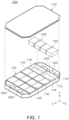
- FIG. 1 illustrates a battery pack 1000 according to an exemplary embodiment.
- the battery pack 1000 in an exemplary embodiment may include a pack housing 1100 and a plurality of cell stack bodies 1200 accommodated in the pack housing 1100.
- the pack housing 1100 may include a lower plate 1110, a side plate 1120 disposed on an edge of the lower plate 1110, a partition wall 1130 partitioning a space surrounded by the side plate 1120 and an upper plate 1150 disposed on the cell stack bodies 1200.
- the upper plate 1150 and/or the lower plate 1110 may function as a cooling plate.
- the lower plate 1110 and/or the upper plate 1150 may be in direct or indirect contact with the cell stack bodies 1200 to dissipate heat generated in the cell stack bodies 1200.
- at least one of the lower plate 1110 and the upper plate 1150 may include a flow path through which a refrigerant flows.
- An internal space of the pack housing 1100 may be divided into several compartments by the partition wall 1130, and at least one cell stack body 1200 may be disposed in each compartment.
- FIG. 1 illustrates that one cell stack body 1200 is disposed in one compartment, which is only an example, and two or more cell stack bodies 1200 may be disposed therein.
- FIG. 1 illustrates that four electronic components 1300 are disposed in the pack housing 1100, which is only an example, and the number or positions of the electronic components 1300 in another exemplary embodiment may differ from those in the described exemplary embodiment.
- At least one electronic component 1300 may be disposed in the pack housing 1100.
- the electronic component 1300 may include a battery management system (BMS), a power relay assembly (PRA), a electric power management device, a battery charge/discharge device, and an input port of the battery pack 1000, an output port of the battery pack 1000, a device for sensing a battery state (e.g. voltage, lifespan, temperature, pressure or the like), a device for battery safety, a electric power cut-off system, a device for slow or fast charging, etc.
- a device not explicitly mentioned in the present disclosure may be included in the electronic component 1300 of the present disclosure as long as the device is an electronic device disposed in the battery pack 1000.
- the battery pack 1000 may include a connecting member 1400 electrically connecting two or more of the cell stack bodies 1200 or the electronic components 1300 to each other.
- the cell stack body 1200 may be electrically connected to another cell stack body 1200 in the battery pack 1000 by the connecting member 1400.
- the electronic component 1300 may be electrically connected to another electronic component 1300 in the battery pack 1000 by the connecting member 1400.
- the cell stack body 1200 may be electrically connected to the electronic component 1300 in the battery pack 1000 by the connecting member 1400.
- the connecting member 1400 may electrically connect at least two different components in the battery pack 1000 to each other.
- the connecting member 1400 may be a wiring harness or a bus bar.
- the connecting member 1400 may be an electronic wiring for high voltage or an electronic wiring for low voltage.
- a high current may flow between the cell stack bodies 1200, and the connecting member 1400 connecting the cell stack bodies 1200 to each other may thus be the electronic wiring for high voltage.
- the connecting member 1400 connected to the corresponding electronic component 1300 may be the electronic wiring for high voltage.
- the connecting member 1400 electrically connecting the battery management system (BMS) and the cell stack body 1200 to each other may be the electronic wiring for low voltage.
- the connecting member 1400 may be a bus bar connected to the input/output port (or port block) of the cell stack body 1200.
- the connecting member 1400 may be a low voltage (LV) harness connected to the battery management system (BMS) .
- BMS battery management system
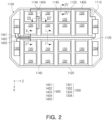
- FIG. 2 illustrates the component in the battery pack 1000 and the connecting member connected to the components.
- the connecting member 1400 may electrically connect the electronic component 1300 and the cell stack body 1200 to each other, or electrically connect the electronic components 1300 to each other or the cell stack bodies 1200 to each other.
- FIG. 2 illustrates, as an example of the connecting member 1400, a first connecting member 1401 connecting a first electronic component 1301 and a third electronic component 1303 to each other, a second connecting member 1402 connecting the first electronic component 1301 and the cell stack body 1200 to each other, a third connecting member 1403 connecting a second electronic component 1302 and the cell stack body 1200 to each other, a fourth connecting member 1404 connecting the cell stack bodies 1200 to each other, and a fifth connecting member 1405 connecting the third electronic component 1303 and the cell stack body 1200 to each other.
- the first to fifth connecting members 1401, 1402, 1403, 1404 and 1405 illustrated in FIG. 2 are only examples for convenience of description, and an exemplary embodiment of the present disclosure is not limited thereto. That is, the battery pack 1000 may include another type connecting member or an additional connecting member different from the first to fifth connecting members 1401, 1402, 1403, 1404 and 1405 illustrated in FIG. 2 .
- the pack housing 1100 may include the partition wall 1130 and 1140 , partitioning the internal space of the pack housing 1100.
- the pack housing 1100 may include a first partition wall 1130 passing through the internal space in the X-direction.
- the pack housing 1100 may include a second partition wall 1140 passing through the internal space in the Z-direction.
- the partition walls 1130 and 1140 illustrated in FIGS. 1 and 2 are only examples, and an exemplary embodiment of the present disclosure is not limited thereto.
- the connecting member 1400 may be accommodated in the partition wall 1130 or 1140.
- the partition wall 1130 or 1140 may include an accommodation portion accommodating the connecting member 1400.
- the accommodation portion may be an internal space of the partition wall 1130 or 1140.
- the accommodation portion may be a recess formed in a side surface of the partition wall 1130 or 1140.
- the connecting member 1400 may be accommodated in the partition wall 1130 or 1140, and an internal space of the battery pack 1000 may thus be efficiently utilized.
- a conventional battery pack may have insufficient internal space, and a connecting member such as the wiring harness or a bus bar for high voltage may thus be positioned in a space between a partition wall and an upper plate.
- the connecting member 1400 may be accommodated in the partition wall 1130 or 1140, and the partition wall 1130 or 1140 may be extended relatively close to the upper plate 1150 from the lower plate 1110.
- the partition wall 1130 or 1140 is extended relatively close to the upper plate 1150 from the lower plate 1110, it is possible to suppress propagation of flame, gas or heat between spaces partitioned by the partition wall 1130 or 1140, which may delay or prevent thermal runaway of the battery pack 1000.
- a general battery pack may include a plurality of battery modules, and the LV harness having a large number of wires in order to obtain information on the plurality of modules may have a complicated shape and occupy a relatively large amount of space.
- the LV harness in a complicated arrangement may act as a factor which may aggravate the event, such as blocking a gas flow path.
- the LV harness may be accommodated in the partition wall 1130 or 1140, thereby preventing the above problem.
- FIG. 3 illustrates the connecting member 1400 accommodated in the partition wall 1130 in an exemplary embodiment.
- FIG. 3 illustrates an example of a cross section of the first partition wall 1130 taken along line I-I' in FIG. 2 .
- the first connecting member 1401 may be accommodated in the first partition wall 1130.
- the first partition wall 1130 may include a void 1131 therein, and the first connecting member 1401 may be accommodated in the void 1131.
- the first partition wall 1130 may have a shape of a hollow square beam, and the first connecting member 1401 may be disposed in the square beam.
- the first connecting member 1401 may be extended in the first partition wall 1130 in a length direction (i.e., X-direction) of the first partition wall 1130, and let out from each of one and the other ends of the first partition wall 1130 to be connected to the electronic component 1300.
- FIG. 2 illustrates that the first connecting member 1401 connects the first electronic component 1301 and the third electronic component 1303 to each other, which is only an example.
- one end of the first connecting member 1401 may be connected to the first electronic component 1301, and the other end of the first connecting member 1401 may be connected to the cell stack body 1200.
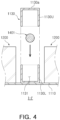
- FIG. 4 illustrates a method of assembling the connecting member 1400 in the partition wall 1130.
- the first partition wall 1130 may include a lower frame 1130L and an upper frame 1130U.
- the upper frame 1130U may be coupled to the lower frame 1130L, and the first connecting member 1401 may thus be accommodated in the first partition wall 1130.
- the lower frame 1130L and the upper frame 1130U may be welded to each other or coupled to each other by using mechanical fastening means such as bolt-nut coupling.
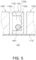
- FIG. 5 illustrates the connecting member accommodated in the recess of the partition wall in an exemplary embodiment.
- FIG. 5 illustrates another example of a cross section of the first partition wall 1130 taken along line I-I' in FIG. 2 .
- the first partition wall 1130 in an exemplary embodiment may include a recess 1132 accommodating the first connecting member 1401.
- the first partition wall 1130 may include a side surface 1132a extended from each of two ends of an upper surface 1130a to the lower plate 1110, and a recessed surface 1132b inward from the side surface 1132a may be defined as a portion of the recess 1132.
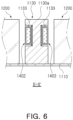
- FIGS. 6 and 7 each illustrate that the connecting member 1400 is accommodated in each of two side surfaces of the partition wall 1130 according to an exemplary embodiment.
- FIG. 6 schematically illustrates the first partition wall 1130, the second connecting member 1402, and the third connecting member 1403, based on a cross section taken along line II-II' of the battery pack 1000 in FIG. 2 .
- the second connecting member 1402 and the third connecting member 1403 may be accommodated in the first partition wall 1130.
- the first partition wall 1130 may include a side surface 1133a extended from each of two ends of the upper surface 1130a to the lower plate 1110, and a recessed surface 1133b inward from the side surface 1133a to form a recess 1133.
- the recess 1133 may have a depth corresponding to a thickness of the connecting member 1400.
- an outer surface of the connecting member 1400 may coincide with or approximately coincide with the side surface 1133a of the first partition wall 1130.
- the connecting member 1400 may include a conductive member 1411 and an insulating member 1412 surrounding at least a portion of the conductive member 1411 to insulate the first partition wall 1130 and the conductive member 1411 from each other.
- the connecting member 1400 may be mounted in the first partition wall 1130 by using an adhesive member 1500.
- the second connecting member 1402 and the third connecting member 1403 may be connected to the electronic component 1300 and the cell stack body 1200, which is only an example.
- the second connecting member 1402 or the third connecting member 1403 may connect the electronic components 1300 to each other or the cell stack bodies 1200 to each other.
- FIG. 8 illustrates the connecting member 1400 accommodated in the partition wall 1130 in an exemplary embodiment.
- FIG. 8 illustrates an example of a cross section of the first partition wall 1130 taken along line II-II' in FIG. 2 .
- the partition wall may include the accommodation portions respectively accommodating two or more connecting members.
- the respective accommodation portions may be spatially separated from each other.
- the first partition wall 1130 may include the void 1131 therein and the recess 1133 formed in the side surface.
- the first connecting member 1401 may be accommodated in the void 1131 in the first partition wall, and the second connecting member 1402 and the third connecting member 1403 may be accommodated in the recesses 1133.
- the void 1131 and the recess 1133 may be spatially separated from each other.
- FIGS. 6 through 8 illustrate that the recess 1133 accommodating the connecting member 1400 is disposed in each of the two side surfaces of the first partition wall 1130, which is only an example.
- the recess 1133 may be disposed only in one side surface of the first partition wall 1130.
- FIGS. 3 through 8 illustrate the connecting member 1400 accommodated in the first partition wall 1130, which is for convenience of description, and a structure included in the pack housing 1100 in addition to the first partition wall 1130 may accommodate the connecting member 1400.
- the connecting member 1400 may also be partially accommodated in the second partition wall 1140 or the side frame 1120. That is, the second partition wall 1140 or the side frame 1120 may include an accommodation portion accommodating at least a portion of the connecting member 1400.
- the accommodation portion may be a void formed in the second partition wall or the side frame or a recess formed in an outer side surface thereof.
- a portion of the fourth connecting member 1404 may be accommodated in the second partition wall 1140, and a portion of the fifth connecting member 1405 may be accommodated in the side frame 1120. That is, the fourth connecting member 1404 and the second partition wall 1140 may each be disposed in a shape similar to that of FIG. 3 , 5 or 6 , based on a cross section taken along line III-III' of FIG. 2 . In addition, the fifth connecting member 1405 and the side frame 1120 may each have a shape similar to that of FIG. 3 , 5 or 6 , based on a cross section taken along line IV-IV' of FIG. 2 .
- the battery pack may have the efficient internal space by effectively arranging the electronic wiring such as the wiring harness and the bus bar therein.
- the battery pack may have the efficient internal space by effectively arranging the electronic wiring such as the wiring harness and the bus bar therein.
Landscapes
- Chemical & Material Sciences (AREA)
- Chemical Kinetics & Catalysis (AREA)
- Electrochemistry (AREA)
- General Chemical & Material Sciences (AREA)
- Engineering & Computer Science (AREA)
- Manufacturing & Machinery (AREA)
- Aviation & Aerospace Engineering (AREA)
- Microelectronics & Electronic Packaging (AREA)
- Battery Mounting, Suspending (AREA)
Abstract
Description
- The present disclosure relates to technology related to a battery pack.
- A secondary battery is a battery which may be charged and discharged unlike a primary battery which is unable to be charged, and may be applied not only to a portable device, but also to an electric vehicle (EV), a hybrid electric vehicle (HEV) or the like, driven by an electric driving source. Types of secondary batteries currently widely used may include a lithium ionbattery, a lithiumpolymer battery, anickel cadmiumbattery, a nickel hydrogen battery, a nickel zinc battery and the like. An operation voltage of a unit cell of the secondary battery, that is, a unit cell of the battery, may be about 2.5 V to 4.6 V. Therefore, when a higher output voltage is required, the plurality of battery cells may be connected in series to each other to form a battery pack. In addition, the plurality of battery cells may be connected to each other in parallel to form the battery pack, based on a charge/discharge capacity required for the battery pack. Accordingly, the number of battery cells included in the battery pack may be variously set based on the required output voltage or charge/discharge capacity.
- Various electronic components such as various battery modules, a battery management system (BMS) and a power relay assembly (PRA) may be positioned in the battery pack, and these electronic components may be connected to each other by electronic wiring. For example, the electronic components may be connected to each other by the electronic wiring such as a wiring harness or a bus bar, which may transmit electric power or an electrical signal.
- Meanwhile, a general battery pack may include a low voltage (LV) harness having a large number of wires in order to obtain information on a plurality of battery modules included in the battery pack. However, the LV harness may have a complicated shape and may occupy a relatively large amount of space. In addition, when an event such as a cell ignition occurs in the battery pack, the LV harness in a complicated arrangement may act as a factor which may aggravate the event, such as blocking a gas flow path.
- An aspect of the present disclosure may provide a battery pack having efficient internal space by effectively arranging electronic wiring such as a wiring harness and a bus bar therein. Another aspect of the present disclosure may provide a battery pack which may prevent electronic wiring therein from aggravating thermal runaway or heat propagation in the pack.
- According to an aspect of the present disclosure, a battery pack may include: a pack housing having an internal space; at least one cell stack body accommodated in the internal space of the pack housing; at least one electronic component accommodated in the internal space of the pack housing; a connecting member electrically connected to at least one of the at least one cell stack body and the at least one electronic component; and a partition wall partitioning the internal space and accommodating at least a portion of the connecting member
- The partition wall may include a void therein, and the connecting member may be accommodated in the void.
- The partition wall may include a lower frame and an upper frame, coupled to the lower frame, and the void may be formed between the lower frame and the upper frame.
- The partition wall may include a recess in a side surface, and the connecting member may be accommodated in the recess.
- The connecting member may include a conductive member and an insulating member surrounding the conductive member.
- The connecting member may be a bus bar connected to an input/output port of the at least one cell stack body.
- The at least one electronic component may be a battery management system (BMS), and the connecting member may be a low voltage (LV) harness connected to the battery management system.
- The partition wall may include a void and a recess, each accommodating the connecting member, and the void and the recess may be spatially separated from each other.
- The above and other aspects, features and advantages of the present disclosure will be more clearly understood from the following detailed description taken in conjunction with the accompanying drawings, in which:
-
FIG. 1 illustrates a battery pack according to an exemplary embodiment; -
FIG. 2 illustrates a component in a pack housing and a connecting member connected to the components; -
FIG. 3 illustrates the connecting member accommodated in a partition wall in an exemplary embodiment; -
FIG. 4 illustrates a method of assembling the connecting member in the partition wall; -
FIG. 5 illustrates the connecting member accommodated in a recess of the partition wall in an exemplary embodiment; -
FIGS . 6 and7 each illustrate that the connecting member is accommodated in a side surface of the partition wall according to an exemplary embodiment; and -
FIG. 8 is a view illustrating the connecting members accommodated in an internal space and the recess of the partition wall in an exemplary embodiment. - In this specification, an X-direction, a Y-direction and a Z-direction may indicate a direction parallel to an X axis, a direction parallel to a Y axis, and a direction parallel to a Z axis, each illustrated in the drawings. In addition, unless otherwise described, the X-direction may be a concept including both a +X axis direction and a -X axis direction, which may be equally applied to the Y-direction and the Z-direction.
- In this specification, a case in which two directions (or axes) are parallel to or perpendicular to each other may also include a case in which the two directions (or axes) are substantially parallel or substantially parallel to each other. For example, a case in which the first axis and the second axis are perpendicular to each other may indicate a case in which the first axis and the second axis form an angle of 90 degrees or an angle close to 90 degrees.
-
FIG. 1 illustrates abattery pack 1000 according to an exemplary embodiment. Referring toFIG. 1 , thebattery pack 1000 in an exemplary embodiment may include apack housing 1100 and a plurality ofcell stack bodies 1200 accommodated in thepack housing 1100. Thepack housing 1100 may include alower plate 1110, aside plate 1120 disposed on an edge of thelower plate 1110, apartition wall 1130 partitioning a space surrounded by theside plate 1120 and anupper plate 1150 disposed on thecell stack bodies 1200. Theupper plate 1150 and/or thelower plate 1110 may function as a cooling plate. Thelower plate 1110 and/or theupper plate 1150 may be in direct or indirect contact with thecell stack bodies 1200 to dissipate heat generated in thecell stack bodies 1200. For example, at least one of thelower plate 1110 and theupper plate 1150 may include a flow path through which a refrigerant flows. - An internal space of the
pack housing 1100 may be divided into several compartments by thepartition wall 1130, and at least onecell stack body 1200 may be disposed in each compartment.FIG. 1 illustrates that onecell stack body 1200 is disposed in one compartment, which is only an example, and two or morecell stack bodies 1200 may be disposed therein. In addition,FIG. 1 illustrates that fourelectronic components 1300 are disposed in thepack housing 1100, which is only an example, and the number or positions of theelectronic components 1300 in another exemplary embodiment may differ from those in the described exemplary embodiment. - At least one
electronic component 1300 may be disposed in thepack housing 1100. In the present disclosure, theelectronic component 1300 may include a battery management system (BMS), a power relay assembly (PRA), a electric power management device, a battery charge/discharge device, and an input port of thebattery pack 1000, an output port of thebattery pack 1000, a device for sensing a battery state (e.g. voltage, lifespan, temperature, pressure or the like), a device for battery safety, a electric power cut-off system, a device for slow or fast charging, etc. Even a device not explicitly mentioned in the present disclosure may be included in theelectronic component 1300 of the present disclosure as long as the device is an electronic device disposed in thebattery pack 1000. - The
battery pack 1000 may include a connectingmember 1400 electrically connecting two or more of thecell stack bodies 1200 or theelectronic components 1300 to each other. For example, thecell stack body 1200 may be electrically connected to anothercell stack body 1200 in thebattery pack 1000 by the connectingmember 1400. For another example, theelectronic component 1300 may be electrically connected to anotherelectronic component 1300 in thebattery pack 1000 by the connectingmember 1400. For yet another example, thecell stack body 1200 may be electrically connected to theelectronic component 1300 in thebattery pack 1000 by the connectingmember 1400. - The connecting
member 1400 may electrically connect at least two different components in thebattery pack 1000 to each other. For example, the connectingmember 1400 may be a wiring harness or a bus bar. - According to an exemplary embodiment of the present disclosure, the connecting
member 1400 may be an electronic wiring for high voltage or an electronic wiring for low voltage. - For example, a high current may flow between the
cell stack bodies 1200, and the connectingmember 1400 connecting thecell stack bodies 1200 to each other may thus be the electronic wiring for high voltage. For another example, when theelectronic component 1300 is a component for charging thebattery pack 1000, the connectingmember 1400 connected to the correspondingelectronic component 1300 may be the electronic wiring for high voltage. Meanwhile, the connectingmember 1400 electrically connecting the battery management system (BMS) and thecell stack body 1200 to each other may be the electronic wiring for low voltage. - According to another exemplary embodiment of the present disclosure, the connecting
member 1400 may be a bus bar connected to the input/output port (or port block) of thecell stack body 1200. - For example, the connecting
member 1400 may be a low voltage (LV) harness connected to the battery management system (BMS) . -
FIG. 2 illustrates the component in thebattery pack 1000 and the connecting member connected to the components. Referring toFIG. 2 , the connectingmember 1400 may electrically connect theelectronic component 1300 and thecell stack body 1200 to each other, or electrically connect theelectronic components 1300 to each other or thecell stack bodies 1200 to each other. -
FIG. 2 illustrates, as an example of the connectingmember 1400, a first connectingmember 1401 connecting a firstelectronic component 1301 and a thirdelectronic component 1303 to each other, a second connectingmember 1402 connecting the firstelectronic component 1301 and thecell stack body 1200 to each other, a third connectingmember 1403 connecting a secondelectronic component 1302 and thecell stack body 1200 to each other, a fourth connectingmember 1404 connecting thecell stack bodies 1200 to each other, and a fifth connectingmember 1405 connecting the thirdelectronic component 1303 and thecell stack body 1200 to each other. - The first to fifth connecting
members FIG. 2 are only examples for convenience of description, and an exemplary embodiment of the present disclosure is not limited thereto. That is, thebattery pack 1000 may include another type connecting member or an additional connecting member different from the first to fifth connectingmembers FIG. 2 . - In an exemplary embodiment, the
pack housing 1100 may include thepartition wall pack housing 1100. Thepack housing 1100 may include afirst partition wall 1130 passing through the internal space in the X-direction. Also, thepack housing 1100 may include asecond partition wall 1140 passing through the internal space in the Z-direction. Thepartition walls FIGS. 1 and2 are only examples, and an exemplary embodiment of the present disclosure is not limited thereto. - In an exemplary embodiment, at least a portion of the connecting
member 1400 may be accommodated in thepartition wall partition wall member 1400. For example, the accommodation portion may be an internal space of thepartition wall partition wall - According to an exemplary embodiment of the present disclosure, the connecting
member 1400 may be accommodated in thepartition wall battery pack 1000 may thus be efficiently utilized. - A conventional battery pack may have insufficient internal space, and a connecting member such as the wiring harness or a bus bar for high voltage may thus be positioned in a space between a partition wall and an upper plate.
- However, in the
battery pack 1000 according to an exemplary embodiment of the present disclosure, at least a portion of the connectingmember 1400 may be accommodated in thepartition wall partition wall upper plate 1150 from thelower plate 1110. When thepartition wall upper plate 1150 from thelower plate 1110, it is possible to suppress propagation of flame, gas or heat between spaces partitioned by thepartition wall battery pack 1000. - Meanwhile, a general battery pack may include a plurality of battery modules, and the LV harness having a large number of wires in order to obtain information on the plurality of modules may have a complicated shape and occupy a relatively large amount of space. In addition, when an event such as a cell ignition occurs in the battery pack, the LV harness in a complicated arrangement may act as a factor which may aggravate the event, such as blocking a gas flow path.
- On the other hand, according to an exemplary embodiment of the present disclosure, the LV harness may be accommodated in the
partition wall -
FIG. 3 illustrates the connectingmember 1400 accommodated in thepartition wall 1130 in an exemplary embodiment.FIG. 3 illustrates an example of a cross section of thefirst partition wall 1130 taken along line I-I' inFIG. 2 . - Referring to
FIG. 3 , the first connectingmember 1401 may be accommodated in thefirst partition wall 1130. In detail, thefirst partition wall 1130 may include a void 1131 therein, and the first connectingmember 1401 may be accommodated in thevoid 1131. For example, thefirst partition wall 1130 may have a shape of a hollow square beam, and the first connectingmember 1401 may be disposed in the square beam. - Referring to
FIG. 2 together, the first connectingmember 1401 may be extended in thefirst partition wall 1130 in a length direction (i.e., X-direction) of thefirst partition wall 1130, and let out from each of one and the other ends of thefirst partition wall 1130 to be connected to theelectronic component 1300.FIG. 2 illustrates that the first connectingmember 1401 connects the firstelectronic component 1301 and the thirdelectronic component 1303 to each other, which is only an example. In another exemplary embodiment, one end of the first connectingmember 1401 may be connected to the firstelectronic component 1301, and the other end of the first connectingmember 1401 may be connected to thecell stack body 1200. -
FIG. 4 illustrates a method of assembling the connectingmember 1400 in thepartition wall 1130. Referring toFIG. 4 , thefirst partition wall 1130 may include alower frame 1130L and anupper frame 1130U. In a state where the first connectingmember 1401 is disposed in thelower frame 1130L, theupper frame 1130U may be coupled to thelower frame 1130L, and the first connectingmember 1401 may thus be accommodated in thefirst partition wall 1130. For example, thelower frame 1130L and theupper frame 1130U may be welded to each other or coupled to each other by using mechanical fastening means such as bolt-nut coupling. -
FIG. 5 illustrates the connecting member accommodated in the recess of the partition wall in an exemplary embodiment.FIG. 5 illustrates another example of a cross section of thefirst partition wall 1130 taken along line I-I' inFIG. 2 . Referring toFIG. 5 , thefirst partition wall 1130 in an exemplary embodiment may include arecess 1132 accommodating the first connectingmember 1401. For example, thefirst partition wall 1130 may include aside surface 1132a extended from each of two ends of anupper surface 1130a to thelower plate 1110, and a recessedsurface 1132b inward from theside surface 1132a may be defined as a portion of therecess 1132. -
FIGS. 6 and7 each illustrate that the connectingmember 1400 is accommodated in each of two side surfaces of thepartition wall 1130 according to an exemplary embodiment.FIG. 6 schematically illustrates thefirst partition wall 1130, the second connectingmember 1402, and the third connectingmember 1403, based on a cross section taken along line II-II' of thebattery pack 1000 inFIG. 2 . - In an exemplary embodiment, the second connecting
member 1402 and the third connectingmember 1403 may be accommodated in thefirst partition wall 1130. Thefirst partition wall 1130 may include aside surface 1133a extended from each of two ends of theupper surface 1130a to thelower plate 1110, and a recessedsurface 1133b inward from theside surface 1133a to form arecess 1133. Therecess 1133 may have a depth corresponding to a thickness of the connectingmember 1400. For example, when the connectingmember 1400 is accommodated in thefirst partition wall 1130, an outer surface of the connectingmember 1400 may coincide with or approximately coincide with theside surface 1133a of thefirst partition wall 1130. - Referring to
FIG. 7 , the connectingmember 1400 may include aconductive member 1411 and an insulatingmember 1412 surrounding at least a portion of theconductive member 1411 to insulate thefirst partition wall 1130 and theconductive member 1411 from each other. The connectingmember 1400 may be mounted in thefirst partition wall 1130 by using anadhesive member 1500. - Referring to
FIG. 2 together, the second connectingmember 1402 and the third connectingmember 1403 may be connected to theelectronic component 1300 and thecell stack body 1200, which is only an example. The second connectingmember 1402 or the third connectingmember 1403 may connect theelectronic components 1300 to each other or thecell stack bodies 1200 to each other. -
FIG. 8 illustrates the connectingmember 1400 accommodated in thepartition wall 1130 in an exemplary embodiment.FIG. 8 illustrates an example of a cross section of thefirst partition wall 1130 taken along line II-II' inFIG. 2 . - In an exemplary embodiment, the partition wall may include the accommodation portions respectively accommodating two or more connecting members. The respective accommodation portions may be spatially separated from each other.
- For example, referring to
FIG. 8 , thefirst partition wall 1130 may include the void 1131 therein and therecess 1133 formed in the side surface. The first connectingmember 1401 may be accommodated in the void 1131 in the first partition wall, and the second connectingmember 1402 and the third connectingmember 1403 may be accommodated in therecesses 1133. In addition, thevoid 1131 and therecess 1133 may be spatially separated from each other. - Meanwhile,
FIGS. 6 through 8 illustrate that therecess 1133 accommodating the connectingmember 1400 is disposed in each of the two side surfaces of thefirst partition wall 1130, which is only an example. In another exemplary embodiment, therecess 1133 may be disposed only in one side surface of thefirst partition wall 1130. -
FIGS. 3 through 8 illustrate the connectingmember 1400 accommodated in thefirst partition wall 1130, which is for convenience of description, and a structure included in thepack housing 1100 in addition to thefirst partition wall 1130 may accommodate the connectingmember 1400. - In an exemplary embodiment, the connecting
member 1400 may also be partially accommodated in thesecond partition wall 1140 or theside frame 1120. That is, thesecond partition wall 1140 or theside frame 1120 may include an accommodation portion accommodating at least a portion of the connectingmember 1400. The accommodation portion may be a void formed in the second partition wall or the side frame or a recess formed in an outer side surface thereof. - Referring to
FIG. 2 , a portion of the fourth connectingmember 1404 may be accommodated in thesecond partition wall 1140, and a portion of the fifth connectingmember 1405 may be accommodated in theside frame 1120. That is, the fourth connectingmember 1404 and thesecond partition wall 1140 may each be disposed in a shape similar to that ofFIG. 3 ,5 or6 , based on a cross section taken along line III-III' ofFIG. 2 . In addition, the fifth connectingmember 1405 and theside frame 1120 may each have a shape similar to that ofFIG. 3 ,5 or6 , based on a cross section taken along line IV-IV' ofFIG. 2 . - As set forth above, according to an exemplary embodiment of the present disclosure, the battery pack may have the efficient internal space by effectively arranging the electronic wiring such as the wiring harness and the bus bar therein. In addition, according to an exemplary embodiment of the present disclosure, it is possible to prevent or minimize the thermal runaway or the heat propagation in the battery pack.
- While exemplary embodiments have been shown and described above, it will be apparent to those skilled in the art that modifications and variations could be made without departing from the scope of the present disclosure as defined by the appended claims.
Claims (8)
- A battery pack (1000) comprising:a pack housing (1100) having an internal space;at least one cell stack body (1200) accommodated in the internal space of the pack housing (1100);at least one electronic component (1300) accommodated in the internal space of the pack housing (1100);a connecting member (1400) electrically connected to at least one of the at least one cell stack body (1200) and the at least one electronic component (1300); anda partition wall (1130) partitioning the internal space and accommodating at least a portion of the connecting member (1400).
- The battery pack (1000) of claim 1, wherein the partition wall (1130) includes a void (1131) therein, and the connecting member (1400) is accommodated in the void (1131).
- The battery pack (1000) of claim 2, wherein the partition wall (1130) includes a lower frame (1130L) and an upper frame (1130U), coupled to the lower frame (1130L), and the void (1131) is formed between the lower frame (1130L) and the upper frame (1130U).
- The battery pack (1000) of anyone of the preceding claims, wherein the partition wall (1130) includes a recess (1132) in a side surface, and the connecting member (1400) is accommodated in the recess (1132).
- The battery pack (1000) of anyone of the preceding claims, wherein the connecting member (1400) includes a conductive member (1411) and an insulating member (1412) surrounding the conductive member (1411).
- The battery pack(1000) of anyone of the preceding claims, wherein the connecting member (1400) is a bus bar connected to an input/output port of the at least one cell stack body (1200).
- The battery pack (1000) of anyone of the preceding claims, wherein the at least one electronic component (1300) is a battery management system (BMS), and the connecting member (1400) is a low voltage (LV) harness connected to the battery management system.
- The battery pack (1000) of claim 1, wherein the partition wall (1130) includes a void (1131) and a recess (1132), each accommodating the connecting member (1400), and the void (1131) and the recess (1132) are spatially separated from each other.
Applications Claiming Priority (1)
| Application Number | Priority Date | Filing Date | Title |
|---|---|---|---|
| KR1020210129489A KR20230046464A (en) | 2021-09-30 | 2021-09-30 | battery pack |
Publications (2)
| Publication Number | Publication Date |
|---|---|
| EP4160783A1 true EP4160783A1 (en) | 2023-04-05 |
| EP4160783B1 EP4160783B1 (en) | 2025-01-01 |
Family
ID=83505983
Family Applications (1)
| Application Number | Title | Priority Date | Filing Date |
|---|---|---|---|
| EP22198091.5A Active EP4160783B1 (en) | 2021-09-30 | 2022-09-27 | Battery pack |
Country Status (4)
| Country | Link |
|---|---|
| US (1) | US20230102065A1 (en) |
| EP (1) | EP4160783B1 (en) |
| KR (1) | KR20230046464A (en) |
| CN (1) | CN115882133A (en) |
Cited By (1)
| Publication number | Priority date | Publication date | Assignee | Title |
|---|---|---|---|---|
| EP4611126A4 (en) * | 2022-12-02 | 2025-10-29 | Lg Energy Solution Ltd | BATTERY PACK AND MANUFACTURING METHOD FOR IT |
Families Citing this family (3)
| Publication number | Priority date | Publication date | Assignee | Title |
|---|---|---|---|---|
| KR20240068416A (en) * | 2022-11-10 | 2024-05-17 | 현대자동차주식회사 | Battery pack for vehicle |
| KR102711348B1 (en) * | 2023-11-02 | 2024-09-30 | 덕양산업 주식회사 | Battery pack with improved space utilization and enhanced rigidity |
| CN222394967U (en) * | 2024-04-23 | 2025-01-24 | 惠州亿纬锂能股份有限公司 | Battery pack and electronic equipment |
Citations (3)
| Publication number | Priority date | Publication date | Assignee | Title |
|---|---|---|---|---|
| US20130330595A1 (en) * | 2011-04-26 | 2013-12-12 | Lg Chem, Ltd | Bus bar having novel structure and battery module including the same |
| EP3261154A1 (en) * | 2016-06-17 | 2017-12-27 | SK Innovation Co., Ltd. | Secondary battery pack |
| WO2020177606A1 (en) * | 2019-03-05 | 2020-09-10 | 爱驰汽车有限公司 | Battery pack |
Family Cites Families (3)
| Publication number | Priority date | Publication date | Assignee | Title |
|---|---|---|---|---|
| FR2959606B1 (en) * | 2010-04-28 | 2012-12-28 | Michelin Soc Tech | COMBINED BATTERY BOX FOR ELECTRIC OR HYBRID VEHICLE. |
| FR2963485B1 (en) * | 2010-07-29 | 2013-03-22 | Commissariat Energie Atomique | BATTERY OF ACCUMULATORS DESIGNED AND MOUNTED FACILITIES |
| KR102270234B1 (en) * | 2017-12-12 | 2021-06-25 | 주식회사 엘지에너지솔루션 | Battery module embedding cross beam and Battery pack comprising the battery module |
-
2021
- 2021-09-30 KR KR1020210129489A patent/KR20230046464A/en active Pending
-
2022
- 2022-09-27 EP EP22198091.5A patent/EP4160783B1/en active Active
- 2022-09-27 CN CN202211182712.0A patent/CN115882133A/en active Pending
- 2022-09-30 US US17/958,100 patent/US20230102065A1/en active Pending
Patent Citations (3)
| Publication number | Priority date | Publication date | Assignee | Title |
|---|---|---|---|---|
| US20130330595A1 (en) * | 2011-04-26 | 2013-12-12 | Lg Chem, Ltd | Bus bar having novel structure and battery module including the same |
| EP3261154A1 (en) * | 2016-06-17 | 2017-12-27 | SK Innovation Co., Ltd. | Secondary battery pack |
| WO2020177606A1 (en) * | 2019-03-05 | 2020-09-10 | 爱驰汽车有限公司 | Battery pack |
Cited By (1)
| Publication number | Priority date | Publication date | Assignee | Title |
|---|---|---|---|---|
| EP4611126A4 (en) * | 2022-12-02 | 2025-10-29 | Lg Energy Solution Ltd | BATTERY PACK AND MANUFACTURING METHOD FOR IT |
Also Published As
| Publication number | Publication date |
|---|---|
| EP4160783B1 (en) | 2025-01-01 |
| KR20230046464A (en) | 2023-04-06 |
| US20230102065A1 (en) | 2023-03-30 |
| CN115882133A (en) | 2023-03-31 |
Similar Documents
| Publication | Publication Date | Title |
|---|---|---|
| EP4160783A1 (en) | Battery pack | |
| JP7625653B2 (en) | Top-cooled battery pack | |
| KR102259217B1 (en) | Battery System and Vehicle Comprising the Same | |
| JP5593443B2 (en) | Battery module | |
| EP3273500B1 (en) | Battery system | |
| CN101395737B (en) | Medium or large battery modules | |
| EP2388845B1 (en) | Battery pack | |
| CN103608946A (en) | Battery module and battery assembly including the battery module | |
| CN115692987A (en) | Battery module and battery pack including the same | |
| JP2024537302A (en) | Battery module, battery pack and automobile | |
| US20250192375A1 (en) | Battery and electrical apparatus | |
| KR102825392B1 (en) | Batteries, electrical devices, battery manufacturing methods and devices | |
| KR20240142338A (en) | Battery module with a multifunctional end-plate | |
| CN118318342A (en) | Battery pack with enhanced safety | |
| CN115699409B (en) | Battery packs and vehicles | |
| EP4254605A1 (en) | Battery, electric device, and method and device for preparing battery | |
| KR20230099651A (en) | Battery pack, energy storage system and vehicle comprising the battery pack | |
| KR102951182B1 (en) | Battery, electric device, battery manufacturing method and device | |
| JP2025014119A (en) | Battery pack for electric road vehicle and electric road vehicle equipped with said battery pack | |
| EP4601105A1 (en) | Battery pack and vehicle including same | |
| US20250233230A1 (en) | Scalable cooling structure for a battery cell | |
| KR102954303B1 (en) | Cooling system of battery pack and vehicle comprising the same | |
| US20240234866A9 (en) | Battery module | |
| EP4738590A1 (en) | Battery module, and battery pack and vehicle including same | |
| US20250149717A1 (en) | Battery pack |
Legal Events
| Date | Code | Title | Description |
|---|---|---|---|
| PUAI | Public reference made under article 153(3) epc to a published international application that has entered the european phase |
Free format text: ORIGINAL CODE: 0009012 |
|
| STAA | Information on the status of an ep patent application or granted ep patent |
Free format text: STATUS: THE APPLICATION HAS BEEN PUBLISHED |
|
| AK | Designated contracting states |
Kind code of ref document: A1 Designated state(s): AL AT BE BG CH CY CZ DE DK EE ES FI FR GB GR HR HU IE IS IT LI LT LU LV MC MK MT NL NO PL PT RO RS SE SI SK SM TR |
|
| P01 | Opt-out of the competence of the unified patent court (upc) registered |
Effective date: 20230602 |
|
| STAA | Information on the status of an ep patent application or granted ep patent |
Free format text: STATUS: REQUEST FOR EXAMINATION WAS MADE |
|
| 17P | Request for examination filed |
Effective date: 20230926 |
|
| RBV | Designated contracting states (corrected) |
Designated state(s): AL AT BE BG CH CY CZ DE DK EE ES FI FR GB GR HR HU IE IS IT LI LT LU LV MC MK MT NL NO PL PT RO RS SE SI SK SM TR |
|
| STAA | Information on the status of an ep patent application or granted ep patent |
Free format text: STATUS: EXAMINATION IS IN PROGRESS |
|
| 17Q | First examination report despatched |
Effective date: 20240405 |
|
| GRAP | Despatch of communication of intention to grant a patent |
Free format text: ORIGINAL CODE: EPIDOSNIGR1 |
|
| STAA | Information on the status of an ep patent application or granted ep patent |
Free format text: STATUS: GRANT OF PATENT IS INTENDED |
|
| INTG | Intention to grant announced |
Effective date: 20241008 |
|
| GRAS | Grant fee paid |
Free format text: ORIGINAL CODE: EPIDOSNIGR3 |
|
| GRAA | (expected) grant |
Free format text: ORIGINAL CODE: 0009210 |
|
| STAA | Information on the status of an ep patent application or granted ep patent |
Free format text: STATUS: THE PATENT HAS BEEN GRANTED |
|
| AK | Designated contracting states |
Kind code of ref document: B1 Designated state(s): AL AT BE BG CH CY CZ DE DK EE ES FI FR GB GR HR HU IE IS IT LI LT LU LV MC MK MT NL NO PL PT RO RS SE SI SK SM TR |
|
| REG | Reference to a national code |
Ref country code: GB Ref legal event code: FG4D |
|
| REG | Reference to a national code |
Ref country code: CH Ref legal event code: EP |
|
| REG | Reference to a national code |
Ref country code: DE Ref legal event code: R096 Ref document number: 602022009283 Country of ref document: DE |
|
| REG | Reference to a national code |
Ref country code: IE Ref legal event code: FG4D |
|
| REG | Reference to a national code |
Ref country code: LT Ref legal event code: MG9D |
|
| REG | Reference to a national code |
Ref country code: NL Ref legal event code: MP Effective date: 20250101 |
|
| REG | Reference to a national code |
Ref country code: AT Ref legal event code: MK05 Ref document number: 1757246 Country of ref document: AT Kind code of ref document: T Effective date: 20250101 |
|
| PG25 | Lapsed in a contracting state [announced via postgrant information from national office to epo] |
Ref country code: NL Free format text: LAPSE BECAUSE OF FAILURE TO SUBMIT A TRANSLATION OF THE DESCRIPTION OR TO PAY THE FEE WITHIN THE PRESCRIBED TIME-LIMIT Effective date: 20250101 |
|
| PG25 | Lapsed in a contracting state [announced via postgrant information from national office to epo] |
Ref country code: FI Free format text: LAPSE BECAUSE OF FAILURE TO SUBMIT A TRANSLATION OF THE DESCRIPTION OR TO PAY THE FEE WITHIN THE PRESCRIBED TIME-LIMIT Effective date: 20250101 |
|
| PG25 | Lapsed in a contracting state [announced via postgrant information from national office to epo] |
Ref country code: PL Free format text: LAPSE BECAUSE OF FAILURE TO SUBMIT A TRANSLATION OF THE DESCRIPTION OR TO PAY THE FEE WITHIN THE PRESCRIBED TIME-LIMIT Effective date: 20250101 |
|
| PG25 | Lapsed in a contracting state [announced via postgrant information from national office to epo] |
Ref country code: ES Free format text: LAPSE BECAUSE OF FAILURE TO SUBMIT A TRANSLATION OF THE DESCRIPTION OR TO PAY THE FEE WITHIN THE PRESCRIBED TIME-LIMIT Effective date: 20250101 |
|
| PG25 | Lapsed in a contracting state [announced via postgrant information from national office to epo] |
Ref country code: NO Free format text: LAPSE BECAUSE OF FAILURE TO SUBMIT A TRANSLATION OF THE DESCRIPTION OR TO PAY THE FEE WITHIN THE PRESCRIBED TIME-LIMIT Effective date: 20250401 Ref country code: IS Free format text: LAPSE BECAUSE OF FAILURE TO SUBMIT A TRANSLATION OF THE DESCRIPTION OR TO PAY THE FEE WITHIN THE PRESCRIBED TIME-LIMIT Effective date: 20250501 |
|
| PG25 | Lapsed in a contracting state [announced via postgrant information from national office to epo] |
Ref country code: HR Free format text: LAPSE BECAUSE OF FAILURE TO SUBMIT A TRANSLATION OF THE DESCRIPTION OR TO PAY THE FEE WITHIN THE PRESCRIBED TIME-LIMIT Effective date: 20250101 |
|
| PG25 | Lapsed in a contracting state [announced via postgrant information from national office to epo] |
Ref country code: PT Free format text: LAPSE BECAUSE OF FAILURE TO SUBMIT A TRANSLATION OF THE DESCRIPTION OR TO PAY THE FEE WITHIN THE PRESCRIBED TIME-LIMIT Effective date: 20250502 Ref country code: LV Free format text: LAPSE BECAUSE OF FAILURE TO SUBMIT A TRANSLATION OF THE DESCRIPTION OR TO PAY THE FEE WITHIN THE PRESCRIBED TIME-LIMIT Effective date: 20250101 |
|
| PGFP | Annual fee paid to national office [announced via postgrant information from national office to epo] |
Ref country code: FR Payment date: 20250624 Year of fee payment: 4 |
|
| PG25 | Lapsed in a contracting state [announced via postgrant information from national office to epo] |
Ref country code: BG Free format text: LAPSE BECAUSE OF FAILURE TO SUBMIT A TRANSLATION OF THE DESCRIPTION OR TO PAY THE FEE WITHIN THE PRESCRIBED TIME-LIMIT Effective date: 20250101 Ref country code: GR Free format text: LAPSE BECAUSE OF FAILURE TO SUBMIT A TRANSLATION OF THE DESCRIPTION OR TO PAY THE FEE WITHIN THE PRESCRIBED TIME-LIMIT Effective date: 20250402 |
|
| PG25 | Lapsed in a contracting state [announced via postgrant information from national office to epo] |
Ref country code: AT Free format text: LAPSE BECAUSE OF FAILURE TO SUBMIT A TRANSLATION OF THE DESCRIPTION OR TO PAY THE FEE WITHIN THE PRESCRIBED TIME-LIMIT Effective date: 20250101 |
|
| PG25 | Lapsed in a contracting state [announced via postgrant information from national office to epo] |
Ref country code: CZ Free format text: LAPSE BECAUSE OF FAILURE TO SUBMIT A TRANSLATION OF THE DESCRIPTION OR TO PAY THE FEE WITHIN THE PRESCRIBED TIME-LIMIT Effective date: 20250101 |
|
| PG25 | Lapsed in a contracting state [announced via postgrant information from national office to epo] |
Ref country code: SE Free format text: LAPSE BECAUSE OF FAILURE TO SUBMIT A TRANSLATION OF THE DESCRIPTION OR TO PAY THE FEE WITHIN THE PRESCRIBED TIME-LIMIT Effective date: 20250101 |
|
| REG | Reference to a national code |
Ref country code: DE Ref legal event code: R097 Ref document number: 602022009283 Country of ref document: DE |
|
| PG25 | Lapsed in a contracting state [announced via postgrant information from national office to epo] |
Ref country code: SM Free format text: LAPSE BECAUSE OF FAILURE TO SUBMIT A TRANSLATION OF THE DESCRIPTION OR TO PAY THE FEE WITHIN THE PRESCRIBED TIME-LIMIT Effective date: 20250101 |
|
| PG25 | Lapsed in a contracting state [announced via postgrant information from national office to epo] |
Ref country code: DK Free format text: LAPSE BECAUSE OF FAILURE TO SUBMIT A TRANSLATION OF THE DESCRIPTION OR TO PAY THE FEE WITHIN THE PRESCRIBED TIME-LIMIT Effective date: 20250101 |
|
| PGFP | Annual fee paid to national office [announced via postgrant information from national office to epo] |
Ref country code: DE Payment date: 20250624 Year of fee payment: 4 |
|
| PG25 | Lapsed in a contracting state [announced via postgrant information from national office to epo] |
Ref country code: IT Free format text: LAPSE BECAUSE OF FAILURE TO SUBMIT A TRANSLATION OF THE DESCRIPTION OR TO PAY THE FEE WITHIN THE PRESCRIBED TIME-LIMIT Effective date: 20250101 |
|
| PG25 | Lapsed in a contracting state [announced via postgrant information from national office to epo] |
Ref country code: EE Free format text: LAPSE BECAUSE OF FAILURE TO SUBMIT A TRANSLATION OF THE DESCRIPTION OR TO PAY THE FEE WITHIN THE PRESCRIBED TIME-LIMIT Effective date: 20250101 |
|
| PG25 | Lapsed in a contracting state [announced via postgrant information from national office to epo] |
Ref country code: RO Free format text: LAPSE BECAUSE OF FAILURE TO SUBMIT A TRANSLATION OF THE DESCRIPTION OR TO PAY THE FEE WITHIN THE PRESCRIBED TIME-LIMIT Effective date: 20250101 |
|
| PG25 | Lapsed in a contracting state [announced via postgrant information from national office to epo] |
Ref country code: SK Free format text: LAPSE BECAUSE OF FAILURE TO SUBMIT A TRANSLATION OF THE DESCRIPTION OR TO PAY THE FEE WITHIN THE PRESCRIBED TIME-LIMIT Effective date: 20250101 |
|
| PLBE | No opposition filed within time limit |
Free format text: ORIGINAL CODE: 0009261 |
|
| STAA | Information on the status of an ep patent application or granted ep patent |
Free format text: STATUS: NO OPPOSITION FILED WITHIN TIME LIMIT |
|
| 26N | No opposition filed |
Effective date: 20251002 |