EP4160760A1 - Fuel cell and fuel cell manifold - Google Patents
Fuel cell and fuel cell manifold Download PDFInfo
- Publication number
- EP4160760A1 EP4160760A1 EP21813229.8A EP21813229A EP4160760A1 EP 4160760 A1 EP4160760 A1 EP 4160760A1 EP 21813229 A EP21813229 A EP 21813229A EP 4160760 A1 EP4160760 A1 EP 4160760A1
- Authority
- EP
- European Patent Office
- Prior art keywords
- flow channel
- cell stacked
- gas
- cell
- stacked body
- Prior art date
- Legal status (The legal status is an assumption and is not a legal conclusion. Google has not performed a legal analysis and makes no representation as to the accuracy of the status listed.)
- Pending
Links
Images






Classifications
-
- H—ELECTRICITY
- H01—ELECTRIC ELEMENTS
- H01M—PROCESSES OR MEANS, e.g. BATTERIES, FOR THE DIRECT CONVERSION OF CHEMICAL ENERGY INTO ELECTRICAL ENERGY
- H01M8/00—Fuel cells; Manufacture thereof
- H01M8/24—Grouping of fuel cells, e.g. stacking of fuel cells
- H01M8/2465—Details of groupings of fuel cells
- H01M8/2483—Details of groupings of fuel cells characterised by internal manifolds
-
- H—ELECTRICITY
- H01—ELECTRIC ELEMENTS
- H01M—PROCESSES OR MEANS, e.g. BATTERIES, FOR THE DIRECT CONVERSION OF CHEMICAL ENERGY INTO ELECTRICAL ENERGY
- H01M8/00—Fuel cells; Manufacture thereof
- H01M8/02—Details
- H01M8/0202—Collectors; Separators, e.g. bipolar separators; Interconnectors
- H01M8/0258—Collectors; Separators, e.g. bipolar separators; Interconnectors characterised by the configuration of channels, e.g. by the flow field of the reactant or coolant
-
- H—ELECTRICITY
- H01—ELECTRIC ELEMENTS
- H01M—PROCESSES OR MEANS, e.g. BATTERIES, FOR THE DIRECT CONVERSION OF CHEMICAL ENERGY INTO ELECTRICAL ENERGY
- H01M8/00—Fuel cells; Manufacture thereof
- H01M8/02—Details
- H01M8/0202—Collectors; Separators, e.g. bipolar separators; Interconnectors
- H01M8/0267—Collectors; Separators, e.g. bipolar separators; Interconnectors having heating or cooling means, e.g. heaters or coolant flow channels
-
- H—ELECTRICITY
- H01—ELECTRIC ELEMENTS
- H01M—PROCESSES OR MEANS, e.g. BATTERIES, FOR THE DIRECT CONVERSION OF CHEMICAL ENERGY INTO ELECTRICAL ENERGY
- H01M8/00—Fuel cells; Manufacture thereof
- H01M8/04—Auxiliary arrangements, e.g. for control of pressure or for circulation of fluids
- H01M8/04007—Auxiliary arrangements, e.g. for control of pressure or for circulation of fluids related to heat exchange
- H01M8/04029—Heat exchange using liquids
-
- H—ELECTRICITY
- H01—ELECTRIC ELEMENTS
- H01M—PROCESSES OR MEANS, e.g. BATTERIES, FOR THE DIRECT CONVERSION OF CHEMICAL ENERGY INTO ELECTRICAL ENERGY
- H01M8/00—Fuel cells; Manufacture thereof
- H01M8/24—Grouping of fuel cells, e.g. stacking of fuel cells
- H01M8/241—Grouping of fuel cells, e.g. stacking of fuel cells with solid or matrix-supported electrolytes
-
- H—ELECTRICITY
- H01—ELECTRIC ELEMENTS
- H01M—PROCESSES OR MEANS, e.g. BATTERIES, FOR THE DIRECT CONVERSION OF CHEMICAL ENERGY INTO ELECTRICAL ENERGY
- H01M8/00—Fuel cells; Manufacture thereof
- H01M8/24—Grouping of fuel cells, e.g. stacking of fuel cells
- H01M8/2457—Grouping of fuel cells, e.g. stacking of fuel cells with both reactants being gaseous or vaporised
-
- H—ELECTRICITY
- H01—ELECTRIC ELEMENTS
- H01M—PROCESSES OR MEANS, e.g. BATTERIES, FOR THE DIRECT CONVERSION OF CHEMICAL ENERGY INTO ELECTRICAL ENERGY
- H01M8/00—Fuel cells; Manufacture thereof
- H01M8/24—Grouping of fuel cells, e.g. stacking of fuel cells
- H01M8/2465—Details of groupings of fuel cells
- H01M8/2484—Details of groupings of fuel cells characterised by external manifolds
-
- H—ELECTRICITY
- H01—ELECTRIC ELEMENTS
- H01M—PROCESSES OR MEANS, e.g. BATTERIES, FOR THE DIRECT CONVERSION OF CHEMICAL ENERGY INTO ELECTRICAL ENERGY
- H01M8/00—Fuel cells; Manufacture thereof
- H01M8/24—Grouping of fuel cells, e.g. stacking of fuel cells
- H01M8/249—Grouping of fuel cells, e.g. stacking of fuel cells comprising two or more groupings of fuel cells, e.g. modular assemblies
-
- H—ELECTRICITY
- H01—ELECTRIC ELEMENTS
- H01M—PROCESSES OR MEANS, e.g. BATTERIES, FOR THE DIRECT CONVERSION OF CHEMICAL ENERGY INTO ELECTRICAL ENERGY
- H01M8/00—Fuel cells; Manufacture thereof
- H01M8/10—Fuel cells with solid electrolytes
- H01M2008/1095—Fuel cells with polymeric electrolytes
-
- Y—GENERAL TAGGING OF NEW TECHNOLOGICAL DEVELOPMENTS; GENERAL TAGGING OF CROSS-SECTIONAL TECHNOLOGIES SPANNING OVER SEVERAL SECTIONS OF THE IPC; TECHNICAL SUBJECTS COVERED BY FORMER USPC CROSS-REFERENCE ART COLLECTIONS [XRACs] AND DIGESTS
- Y02—TECHNOLOGIES OR APPLICATIONS FOR MITIGATION OR ADAPTATION AGAINST CLIMATE CHANGE
- Y02E—REDUCTION OF GREENHOUSE GAS [GHG] EMISSIONS, RELATED TO ENERGY GENERATION, TRANSMISSION OR DISTRIBUTION
- Y02E60/00—Enabling technologies; Technologies with a potential or indirect contribution to GHG emissions mitigation
- Y02E60/30—Hydrogen technology
- Y02E60/50—Fuel cells
Definitions
- Embodiments according to the present invention relate to a fuel cell and a manifold for a fuel cell.
- a fuel cell is a power generation device which, via chemical reaction of fuel such as hydrogen and oxidant such as air, directly converts the fuel's chemical energy into electric energy and take this converted energy to the outside.
- fuel such as hydrogen
- oxidant such as air
- gas manifolds for feeding a fuel gas, an oxidant gas and the like are provided on the exterior of a stacked body of unit cells (elements).
- Patent Literature 1 Japanese Patent No. 3425086
- an object of an embodiment of the present invention is to provide a fuel cell and a manifold for a fuel cell capable of more easily modifying output of the fuel cell in an external manifold scheme.
- a fuel cell includes a cell stacked body and a manifold.
- the cell stacked body has elements stacked, each element having: an electrolyte membrane; a fuel electrode and an oxidant electrode between which the electrolyte membrane is interposed; a fuel electrode flow channel plate in which a gas flow channel facing the fuel electrode is provided; and an oxidant electrode flow channel plate in which a gas flow channel facing the oxidant electrode is provided.
- the manifold is provided on a lateral surface, of the cell stacked body, along a stacking direction of the cell stacked body and feeds a reaction gas to the fuel electrode flow channel plate or the oxidant electrode flow channel plate in the cell stacked body.
- the manifold includes a gas flow channel part that is provided between a plurality of the cell stacked bodies arranged to line up in a first direction perpendicular to the stacking direction and that allows communication between the cell stacked bodies such that the reaction gas passes through.
- FIG. 1 is a perspective view showing an example of a structure of a fuel cell 1 having manifolds taken off.
- Figure 2 is a perspective view showing an example of a structure of the fuel cell 1 in the state where the manifolds are mounted.
- the fuel cell 1 according to a first embodiment is a structure body which generates electric power via electrochemical reaction in fuel cell elements.
- the fuel cell 1 is configured to include a cell stacked body 10, two current collector plates 20, two insulating plates 25, a fuel cell fastening structure body 30, a first manifold 40, a second manifold 42, a third manifold 44, and a fourth manifold 46.
- the cell stacked body 10 has a plurality of fuel cell elements 10a stacked.
- Each fuel cell element 10a generates electric power via electrochemical reaction of a fuel electrode gas containing hydrogen and an oxidant electrode gas containing oxygen.
- the cell stacked body 10 is a structure body in which the plurality of fuel cell elements 10a are connected in series. A detailed configuration of the fuel cell element 10a is mentioned later.
- Figure 1 and Figure 2 each show a Z-direction parallel to a stacking direction of the cell stacked body 10, and an X-direction and a Y-direction which are perpendicular to the Z-direction and parallel to each other.
- the Z-direction is parallel to the direction of gravity.
- the two current collector plates 20 are arranged on both sides of the cell stacked body 10 in the stacking direction.
- the two current collector plates 20 are plate-like conductors, and are respectively arranged on both end faces of the cell stacked body 10.
- the two insulating plates 25 are plate-like insulators, and are respectively arranged between the two current collector plates 20 and the two fastening plates 100.
- the two current collector plates 20 and the two insulating plates 25 are sequentially arranged on both sides of the cell stacked body 10 in the stacking direction, and integrally fastening these from both sides in the stacking direction with the two fastening plates 100 affords the fuel cell 1.
- the fuel cell fastening structure body 30 is a structure body which exerts surface pressure onto the cell stacked body 10, and is configured to include the two fastening plates 100 and a plurality of coupling members 200.
- the two fastening plates 100 are members which fasten the cell stacked body 10 from both sides, in the stacking direction, of the cell stacked body 10 having a plurality of fuel cell elements stacked.
- Each fastening plate 100 has a pressing part 110 and beam parts 120. These pressing part 110 and beam parts 120 are integrally formed. Notably, the pressing part 110 and the beam parts 120 may be separately configured.
- the coupling members 200 are members which couple the two fastening plates 100. Namely, each coupling member 200 according to the present embodiment has a tie rod 202, two washers 204, and two nuts 206. As shown in Figure 1 , the two fastening plates 100 are coupled by the nuts 206 fastened via the washers 204 in the state where the tie rods 202 are inserted through respective opposing hole parts provided in the two fastening plates 100.
- the manifolds 40, 42, 44, and 46 are mounted on lateral surfaces of the cell stacked body 10 along the stacking direction of the cell stacked body 10 in the fuel cell 1.
- the manifolds are members including spatial regions for feeding reaction gases such as the fuel electrode gas and the oxidant electrode gas, cooling water, and the like.
- the first manifold 40 has a cooling water manifold and an oxidant electrode manifold.
- the second manifold 42 is a fuel electrode manifold.
- the third manifold 44 is a manifold opposite to the first manifold 40, and has a cooling water manifold and an oxidant electrode manifold. Namely, the first manifold 40 and the third manifold 44 are respectively arranged on opposite sides of the lateral surfaces of the cell stacked body 10.
- the fourth manifold 46 is a manifold opposite to the second manifold 42, and is a fuel electrode manifold. Namely, the second manifold 42 and the fourth manifold 46 are respectively arranged on opposite sides of the lateral surfaces of the cell stacked body 10.
- Cooling water introduced from a piping joint part 40a is fed from the lateral surface of the cell stacked body 10 and is discharged from a piping joint part 44a via cooling water flow channel grooves of each fuel cell element 10a.
- the oxidant electrode gas is introduced from a piping joint part 40b, and the oxidant electrode gas that is not consumed by the electrochemical reaction in the cell stacked body 10 is discharged from a piping joint part 40c.
- the fuel electrode gas is introduced from a piping joint part 42a, and the fuel electrode gas that is not consumed by the electrochemical reaction in the cell stacked body 10 is discharged from a piping joint part 42b.
- Manifolds 40, 42, 44, and 46 Gas impermeability is required for the manifolds 40, 42, 44, and 46. Moreover, pressure is higher inside the manifolds than outside the manifolds. Therefore, the manifolds 40, 42, 44, and 46 are configured as molded articles of rigid resin or metal which can be generally resistant to a pressure difference between the interior and the exterior of the manifolds.
- FIG. 3 is an exploded perspective view showing an example of a configuration of a fuel cell element.
- the fuel cell element 10a is configured to include an electrolyte membrane 12, a fuel electrode flow channel plate 14, and an oxidant electrode flow channel plate 16.
- This electrolyte membrane 12 has a fuel electrode formed on one principal plane 12a and an oxidant electrode formed on the other principal plane 12b.
- the fuel cell element 10a includes the fuel electrode and the oxidant electrode provided such that the electrolyte membrane 12 is interposed (sandwiched) therebetween.
- the electrolyte membrane 12 is a polymer electrolyte membrane, for example.
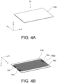
- Figure 4 shows views showing an example of a configuration of the fuel electrode flow channel plate 14
- Figure 4A is a view showing a shape of a principal plane 14a side of the fuel electrode flow channel plate 14
- Figure 4B is a view showing a shape of a principal plane 14b side of the fuel electrode flow channel plate 14.
- the principal plane 14a of the fuel electrode flow channel plate 14 is on the opposite side to the fuel electrode of the electrolyte membrane 12, and forms a flat surface.
- the fuel electrode flow channel plate 14 has, on the principal plane 14b on the fuel electrode side of the electrolyte membrane 12, fuel electrode gas flow channel grooves 140b provided along the fuel electrode. Moreover, the fuel electrode gas flow channel grooves 140b have a first inlet part 14c, a first outlet part 14d, a second inlet part 14e, and a second outlet part 14f.
- the fuel electrode gas introduced from the first inlet part 14c flows along the fuel electrode gas flow channel grooves 140b and is discharged from the first outlet part 14d.
- the fuel electrode gas introduced from the second inlet part 14e flows along the fuel electrode gas flow channel grooves 140b and is discharged from the second outlet part 14f.
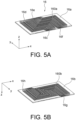
- Figure 5 shows views showing an example of a configuration of the oxidant electrode flow channel plate 16
- Figure 5A is a view showing a shape of a principal plane 16a of the oxidant electrode flow channel plate
- Figure 5B is a view showing a shape of a principal plane 16b on the opposite side to the principal plane 16a of the oxidant electrode flow channel plate 16.
- the oxidant electrode flow channel plate 16 has, on the principal plane 16a on the oxidant electrode side of the electrolyte membrane 12, oxidant gas flow channel grooves 160a provided along the oxidant electrode.
- the oxidant gas flow channel grooves 160a have a first inlet part 16c, a first outlet part 16d, a second inlet part 16e, and a second outlet part 16f.
- An oxidant gas introduced from the first inlet part 16c flows along the oxidant gas flow channel grooves 160a and is discharged from the first outlet part 16d.
- the oxidant gas introduced from the second inlet part 16e flows along the oxidant gas flow channel grooves 160a and is discharged from the second outlet part 16f.
- cooling water flow channel grooves 160b are provided on the principal plane 16b on the opposite side to the oxidant electrode side.
- the cooling water flow channel grooves 160b have a first inlet part 16h and a first outlet part 16g.
- the cooling water introduced from the first inlet part 16h flows along the cooling water flow channel grooves 160b and is discharged from the first outlet part 16g.
- the oxidant electrode flow channel plate 16 is configured of a conductive porous plate having micropores, for example.
- the cooling water flow channel grooves 160b vaporize the cooling water from their surfaces to humidify the fuel cell element 10a.
- the oxidant electrode flow channel plate 16 that does not have the cooling water flow channel grooves 160b may be used.
- the first manifold 40 and the third manifold 44 may be configured only of oxidant electrode manifolds.
- the plurality of these fuel cell elements 10a generate electric power via reaction expressed by chemical formula 1.
- the fuel electrode gas is a hydrogen-containing gas, for example.
- the fuel electrode gas flows along the fuel electrode gas flow channel grooves 140b of the fuel electrode flow channel plate 14 and causes a fuel electrode reaction to occur.
- the oxidant gas is an oxygen-containing gas, for example.
- the oxidant gas flows along the oxidant gas flow channel grooves 160a of the oxidant electrode flow channel plate 16 and causes an oxidant electrode reaction to occur.
- the fuel cell 1 takes out electric energy from electrodes provided on the current collector plates 20 ( Figure 1 ).
- Figure 6 is a view showing an example of a configuration of the front side of the fastening plate 100 and a configuration of a terminal 300.
- the fastening plate 100 has the terminal 300 and a terminal cover 310 mounted.
- This terminal 300 is electrically connected to the current collector plate 20.
- a terminal 300 is also provided on the lower side in the stacking direction, not only on the upper side in the stacking direction.
- the two terminals 300 provided at both ends in the stacking direction are a positive electrode terminal and a negative electrode terminal, for example.
- details of the terminals 300 are described later with reference to Figure 10 .
- Figure 7 is a schematic diagram showing a configuration of the fuel cell 1 according to the first embodiment.
- circles shown on the manifolds 40, 42, 44, and 46 designates the piping joint parts 40a, 40b, 40c, 42a, 42b, and 44a shown in Figure 2 .
- Figure 7 shows collecting pipes for the fuel electrode gas.
- the collecting pipes for the fuel electrode gas are connected to the piping joint parts 42a and 42b shown in Figure 2 .
- Figure 7 does not show the fuel cell fastening structure body 30 shown in Figure 1 and Figure 2 .
- the cell stacked bodies 10 may be provided with distances between the cell stacked bodies 10 wide enough, for example, such that the coupling members 200 can be provided therebetween.
- the fuel cell 1 further includes fifth manifolds 48.
- the manifolds 40, 42, 44, 46, and 48 feed the fuel electrode gas to the fuel electrode flow channel plates 14 in the cell stacked bodies 10, and feed the oxidant gas and the cooling water to the oxidant electrode flow channel plates 16 therein.
- the plurality of cell stacked bodies 10 are arranged to line up in a first direction perpendicular to the stacking direction.
- the first direction is the Y-direction.
- the cell stacked bodies 10 are arranged such that the orientation of each of them in the Z-direction is reverse to that of adjacent one of the cell stacked bodies 10.
- the cell stacked bodies 10 are arranged such that each of them rotates relative to adjacent one of the cell stacked bodies 10 by 180° around the Y-direction.
- the fifth manifolds 48 are provided between the cell stacked bodies 10 arranged to line up in the first direction (Y-direction). As shown in Figure 7 , for the cell stacked body 10 that is at one end in the first direction, the fifth manifold and the first manifold 40 are arranged on the respective opposite lateral surfaces of the cell stacked body 10. Moreover, for the cell stacked body 10 that is at the other end in the first direction, the fifth manifold and the third manifold 44 are arranged on the respective opposite lateral surfaces of the cell stacked body 10.
- Figure 8 shows schematic diagrams showing configurations of the first manifold 40, the third manifold 44, and the fifth manifold 48 according to the first embodiment.
- Figure 8A is a schematic diagram showing a shape of the first manifold 40 as horizontally viewed from the cell stacked body 10 side
- Figure 8B is a schematic diagram showing a shape of the third manifold 44 as horizontally viewed from the cell stacked body 10 side
- Figure 8C is a schematic diagram showing a shape of the fifth manifold 48 as horizontally viewed from the side of the cell stacked body 10 that the first manifold 40 is provided on.
- the first manifold 40 includes the oxidant manifold which feeds the oxidant gas, and the cooling water manifold which feeds the cooling water.
- the oxidant manifold of the first manifold 40 includes the piping joint part 40b, the piping joint part 40c, a gas introducing part 40d, and a gas discharging part 40e.
- the cooling water manifold of the first manifold 40 includes the piping joint part 40a and a cooling water introducing part 40f.
- the piping joint part 40a is a joint part for feeding and communicates with the cooling water introducing part 40f. This piping joint part 40a feeds the cooling water to the cooling water introducing part 40f.
- the piping joint part 40b is a joint part for feeding and communicates with the gas introducing part 40d. This piping joint part 40b feeds the reaction gas (oxidant gas) to the gas introducing part 40d.
- the piping joint part 40c is a joint part for discharging and communicates with the gas discharging part 40e. This piping joint part 40c discharges an unreacted gas which is not consumed by the electrochemical reaction from the gas discharging part 40e.
- the gas introducing part 40d, the gas discharging part 40e, and the cooling water introducing part 40f are a plurality of spatial region parts arranged along the lateral surface of the cell stacked body 10 along the cell stacking direction. Notably, the gas introducing part 40d, the gas discharging part 40e, and the cooling water introducing part 40f do not communicate (penetrate) in the Y-direction.
- an area where the gas introducing part 40d is in contact with the lateral surface of the cell stacked body 10 is wider than an area where the gas discharging part 40e is in contact with the lateral surface of the cell stacked body 10.
- the oxidant gas is consumed by the electrochemical reaction more at the gas discharging part 40e than at the gas introducing part 40d. Accordingly, since as the amount of oxygen contained in the oxidant gas becomes smaller at the gas discharging part 40e, an area in contact with the oxidant electrodes becomes smaller, a reaction efficiency of the oxidant electrode reaction on the oxidant electrodes is equalized more in the oxidant electrode flow channels.
- the area where the gas introducing part 40d is in contact with the lateral surface of the cell stacked body 10 may be substantially the same as the area where the gas discharging part 40e is in contact with the lateral surface of the cell stacked body 10.
- the third manifold 44 includes the oxidant manifold which feeds the oxidant gas, and the cooling water manifold which feeds the cooling water.
- the oxidant manifold of the third manifold 44 includes a gas passing part 44b.
- the cooling water manifold of the third manifold 44 includes the piping joint part 44a and a cooling water discharging part 44c.
- the piping joint part 44a is a joint part for discharging and communicates with the cooling water discharging part 44c. This piping joint part 44a discharges the cooling water from the cooling water discharging part 44c.
- the gas passing part 44b and the cooling water discharging part 44c are a plurality of spatial region parts arranged along the lateral surface of the cell stacked body 10 along the cell stacking direction. Notably, the gas passing part 44b and the cooling water discharging part 44c do not communicate (penetrate) in the Y-direction.
- the fifth manifold 48 includes an oxidant manifold which feeds the oxidant gas, and a cooling water manifold which feeds the cooling water.
- the oxidant manifold of the fifth manifold 48 includes a gas flow channel part 48a.
- the cooling water manifold of the fifth manifold 48 includes a cooling water flow channel part 48d.
- the gas flow channel part 48a and the cooling water flow channel part 48d are a plurality of spatial region parts arranged along the lateral surface of the cell stacked body 10 along the cell stacking direction.
- the gas flow channel part 48a (a first flow channel part 48b and a second flow channel part 48c) and the cooling water flow channel part 48d communicate (penetrate) in the Y-direction.
- a fifth manifold that is rotated by 180° around the Y-direction is provided on adjacent one of the cell stacked bodies 10 (refer to Figure 7 ).
- the shapes (types) of the fifth manifolds 48 may be the same.
- the gas introducing part 40d is provided, for the cell stacked body 10 that is at one end in the first direction, on the lateral surface that is on the opposite side to the gas flow channel part 48a (fifth manifold 48). Moreover, the gas introducing part 40d introduces the reaction gas (oxidant gas) into the cell stacked body 10. More in detail, the gas introducing part 40d introduces the oxidant gas into a first region of the oxidant gas flow channel grooves 160a in the cell stacked body 10. For example, the first region is a region of the oxidant gas flow channel grooves 160a between the first inlet part 16c ( Figure 5A ) and the first outlet part 16d ( Figure 5A ).
- the gas discharging part 40e is provided on at least part of the lateral surface that the gas introducing part 40d is provided on. Moreover, the gas discharging part 40e discharges the reaction gas (oxidant gas) from the inside of the cell stacked body 10. More in detail, the gas discharging part 40e discharges the oxidant gas from a second region of the oxidant gas flow channel grooves 160a in the cell stacked body 10. For example, the second region is a region of the oxidant gas flow channel grooves 160a between the second inlet part 16e ( Figure 5A ) and the second outlet part 16f ( Figure 5A ).
- the cooling water introducing part 40f is provided, for the cell stacked body 10 that is at the one end in the first direction, on the lateral surface that is on the opposite side to the gas flow channel part 48a (fifth manifold 48). Moreover, the cooling water introducing part 40f introduces the cooling water into the cell stacked body 10.
- the gas passing part 44b is provided, for the cell stacked body 10 that is at the other end in the first direction, on the lateral surface that is on the opposite side to the gas flow channel part 48a (fifth manifold 48). Moreover, the gas passing part 44b allows communication between the first region in the cell stacked body 10 and the second region, in the cell stacked body 10, different from the relevant first region such that the reaction gas (oxidant gas) passes through. More in detail, the gas passing part 44b allows communication between the first region of the oxidant gas flow channel grooves 160a in the cell stacked body 10 and the second region of the oxidant gas flow channel grooves 160a in the cell stacked body 10.
- the cooling water discharging part 44c is provided, for the cell stacked body 10 that is at the other end in the first direction, on the lateral surface that is on the opposite side to the gas flow channel part 48a (fifth manifold 48). Moreover, the cooling water discharging part 44c discharges the cooling water from the inside of the cell stacked body 10.
- the gas flow channel parts 48a are provided between the plurality of cell stacked bodies 10 arranged to line up in the first direction perpendicular to the stacking direction. More in detail, each gas flow channel part 48a is provided between a first lateral surface S1 of a cell stacked body 10 and a second lateral surface S2, of an adjacent cell stacked body 10, that faces the first lateral surface S1. Moreover, the gas flow channel parts 48a allow communication between the cell stacked bodies 10 such that the reaction gas (oxidant gas) passes through. Accordingly, the oxidant gas passes through so as to penetrate the plurality of cell stacked bodies 10 via the gas flow channel parts 48a. Thereby, the number of connection of cell stacked bodies 10 can be more easily modified in accordance with desired output of the fuel cell 1. Consequently, the output of the fuel cell 1 in the external manifold scheme can be more easily modified.
- each gas flow channel part 48a has the first flow channel part 48b and the second flow channel part 48c.
- the first flow channel part 48b allows communication between the first region in the cell stacked body 10 and the first region in the adjacent cell stacked body 10. More in detail, the first flow channel part 48b allows communication between the first region of the oxidant gas flow channel grooves 160a in the cell stacked body 10 and the first region of the oxidant gas flow channel grooves 160a in the adjacent cell stacked body 10.
- the flow channels for the oxidant gas are not the same in the adjacent cell stacked bodies 10.
- the cell stacked body 10 is arranged relative to the adjacent cell stacked body 10 such that the orientations of those in the Z-direction are reverse to each other.
- the oxidant gas advances along the oxidant gas flow channel grooves 160a which are rotated by 180° around the Y-direction.
- the first region is a region of the oxidant gas flow channel grooves 160a between the second outlet part 16f ( Figure 5A ) and the second inlet part 16e ( Figure 5A ), for example.
- the second region is a region of the oxidant gas flow channel grooves 160a between the first outlet part 16d ( Figure 5A ) and the first inlet part 16c ( Figure 5A ), for example.
- the second flow channel part 48c allows communication between the second region in the cell stacked body 10 and the second region in the adjacent cell stacked body. More in detail, the second flow channel part 48c allows communication between the second region of the oxidant gas flow channel grooves 160a in the cell stacked body 10 and the second region of the oxidant gas flow channel grooves 160a in the adjacent cell stacked body 10. Notably, a partition is provided between the first flow channel part 48b and the second flow channel part 48c.
- the cooling water flow channel parts 48d are provided between the plurality of cell stacked bodies 10 arranged to line up in the first direction. Moreover, the cooling water flow channel parts 48d allows communication between the cell stacked bodies 10 such that the cooling water passes through.
- the oxidant gas (air) is fed to the gas introducing part 40d via the piping joint part 40b.
- the oxidant gas flows in the oxidant gas flow channel grooves 160a via the first inlet parts 16c ( Figure 5A ) of the oxidant electrode flow channel plates 16 that communicate with the gas introducing part 40d among the oxidant electrode flow channel plates 16 stacked in the cell stacked body 10, and is discharged from the first outlet parts 16d ( Figure 5A ) to the first flow channel part 48b of the fifth manifold 48.
- the oxidant gas having been discharged to the first flow channel part 48b flows likewise in the oxidant gas flow channel grooves 160a of the oxidant electrode flow channel plates 16, also in the adjacent cell stacked body 10.
- the oxidant gas is discharged to the gas passing part 44b of the third manifold 44.
- the oxidant gas having been discharged to the gas passing part 44b flows in oxidant gas flow channel grooves 160a ( Figure 5A ) via the second inlet parts 16e ( Figure 5A ) of the oxidant electrode flow channel plates 16 that communicate with the gas passing part 44b among the oxidant electrode flow channel plates 16 stacked in the cell stacked body 10, and is discharged from the second outlet parts 16f ( Figure 5A ) to the second flow channel part 48c of the fifth manifold 48.
- the oxidant gas having been discharged to the second flow channel part 48c passes likewise through the oxidant electrode flow channel plates 16, also in the adjacent cell stacked body 10.
- the oxidant gas is discharged to the gas discharging part 40e of the first manifold 40.
- the oxidant gas having been discharged to the gas discharging part 40e is discharged from the piping joint part 40c communicating with the gas discharging part 40e.
- the oxidant gas flows in the oxidant gas flow channel grooves 160a of the oxidant electrode flow channel plates 16 in the cell stacked bodies 10, and thereby, the oxidant gas is fed to the oxidant electrodes of the electrolyte membranes 12. Meanwhile, the oxidant gas is consumed by the electrochemical reaction. Accordingly, a flow rate of the oxidant gas only has to be made larger as the number of cell stacked bodies 10 which the oxidant gas passes through is larger.
- the cooling water is stored in the cooling water introducing part 40f via the piping joint part 40a.
- the cooling water flows in the cooling water flow channel grooves 160b via the first inlet parts 16h ( Figure 5B ) of the oxidant electrode flow channel plates 16 that communicate with the cooling water introducing part 40f, and is discharged from the first outlet parts 16g ( Figure 5B ) to the cooling water flow channel part 48d of the fifth manifold 48.
- the cooling water having been discharged to the cooling water flow channel part 48d flows likewise in the cooling water flow channel grooves 160b of the oxidant electrode flow channel plates 16, also in the adjacent cell stacked body 10. After that, the cooling water is discharged to the cooling water discharging part 44c of the third manifold 44.
- the cooling water stored in the cooling water discharging part 44c is discharged from the piping joint part 44a communicating with the cooling water discharging part 44c. As above, the cooling water flows in the cooling water flow channel grooves 160b of the oxidant electrode flow channel plates 16 in the cell stacked bodies 10, and thereby, the cell stacked bodies 10 are cooled.
- Figure 9 shows schematic diagrams showing configurations of the second manifold 42 and the fourth manifold 46 according to the first embodiment.
- Figure 9A is a schematic diagram showing a shape of the second manifold 42 as horizontally viewed from the cell stacked body 10 side
- Figure 9B is a schematic diagram showing a shape of the fourth manifold 46 as horizontally viewed from the cell stacked body 10 side.
- the second manifold 42 includes the fuel electrode manifold which feeds the fuel electrode gas.
- the fuel electrode manifold of the second manifold 42 includes the piping joint part 42a, the piping joint part 42b, a gas introducing part 42c, and a gas discharging part 42d.
- the piping joint part 42a is a joint part for feeding and communicates with the gas introducing part 42c. This piping joint part 42a feed the reaction gas to the gas introducing part 42c.
- the piping joint part 42b is a joint part for discharging and communicates with the gas discharging part 42d. This piping joint part 42b discharges an unreacted gas which is not consumed by the electrochemical reaction from the gas discharging part 42d.
- the gas introducing part 42c and the gas discharging part 42d are a plurality of spatial region parts arranged along the lateral surface of the cell stacked body 10 along the cell stacking direction.
- the fourth manifold 46 includes the fuel electrode manifold which feeds the fuel electrode gas.
- the fuel electrode manifold of the fourth manifold 46 includes a gas passing part 46a.
- the gas passing part 46a is a spatial region part arranged along the lateral surface of the cell stacked body 10 along the cell stacking direction.
- the gas introducing part 42c is provided on the lateral surface, of the cell stacked body 10, that is on the opposite side to the gas passing part 46a (fourth manifold 46). Moreover, the gas introducing part 42c introduces the oxidant gas into the cell stacked body 10. More in detail, the gas introducing part 42c introduces the fuel electrode gas to a third region of the fuel electrode gas flow channel grooves 140b in the cell stacked body 10. For example, the third region is a region of the fuel electrode gas flow channel grooves 140b between the first inlet part 14c ( Figure 4B ) and the first outlet part 14d ( Figure 4B ).
- the gas discharging part 42d is provided on at least part of the lateral surface that the gas introducing part 42c is provided on. Moreover, the gas discharging part 42d discharges the fuel electrode gas from the cell stacked body 10. More in detail, the gas discharging part 42d discharges the fuel electrode gas from a fourth region of the fuel electrode gas flow channel grooves 140b in the cell stacked body 10.
- the fourth region is a region of the fuel electrode gas flow channel grooves 140b between the second inlet part 14e ( Figure 4B ) and the second outlet part 14f ( Figure 4B ).
- the gas passing part 46a is provided, for the cell stacked body 10, on the lateral surface that is on the opposite side to the gas introducing part 42c (second manifold 42). Moreover, the gas passing part 46a allows communication between the third region in the cell stacked body 10 and the fourth region, in the cell stacked body 10, different from the relevant third region such that the fuel electrode gas passes through. More in detail, the gas passing part 46a allows communication between the third region of the fuel electrode gas flow channel grooves 140b in the cell stacked body 10 and the fourth region of the fuel electrode gas flow channel grooves 140b in the cell stacked body 10.
- the fuel electrode gas (fuel) is fed to the gas introducing part 42c via the piping joint part 42a.
- the fuel electrode gas flows in the fuel electrode gas flow channel grooves 140b ( Figure 4B ) via the first inlet parts 14c of the fuel electrode flow channel plates 14 that communicate with the gas introducing part 42c among the fuel electrode flow channel plates 14 stacked in the cell stacked body 10, and is discharged from the first outlet parts 14d ( Figure 4B ) to the gas passing part 46a of the fourth manifold 46.
- the fuel electrode gas having been discharged to the gas passing part 46a flows in the fuel electrode gas flow channel grooves 140b ( Figure 4B ) via the second inlet parts 14e ( Figure 4B ) of the fuel electrode flow channel plates 14 that communicate with the gas passing part 46a among the fuel electrode flow channel plates 14 stacked in the cell stacked body 10, and is discharged from the second outlet parts 14f ( Figure 4B ) to the gas discharging part 42d of the second manifold 42.
- the fuel electrode gas having been discharged to the gas discharging part 42d is discharged from the piping joint part 42b communicating with the gas discharging part 42d.
- the fuel electrode gas flows in the fuel electrode gas flow channel grooves 140b of the fuel electrode flow channel plates 14 in the cell stacked bodies 10, and thereby, the fuel electrode gas is fed to the fuel electrodes of the electrolyte membranes 12.
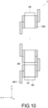
- Figure 10 is a schematic diagram showing arrangement and electric connection of the cell stacked bodies 10 according to the first embodiment.
- the terminals 300 described with reference to Figure 6 that is, the positive electrode terminals and the negative electrode terminals are omitted.
- the fastening plates 100 that are denoted with + signs are the fastening plates 100 on the positive electrode terminal sides.
- the fastening plates 100 that are denoted with - signs are the fastening plates 100 on the negative electrode terminal sides.
- the fuel cell 1 further includes the positive electrode terminals, the negative electrode terminals, and electrode connecting parts 401.
- the cell stacked bodies 10 are arranged to line up such that the orientations of the positive electrode terminal and the negative electrode terminal of each of them are reverse to those of adjacent one of the cell stacked bodies 10.
- the positive electrode terminals and the negative electrode terminals are provided in both end parts of the cell stacked bodies 10 in the stacking direction, and are electrically connected to the cell stacked bodies 10 (current collector plates 20).
- the electrode connecting parts 401 electrically connect the positive electrode terminals and the negative electrode terminals of the adjacent cell stacked bodies 10 so as to connect the plurality of cell stacked bodies 10 electrically in series.
- the electrode connecting parts 401 are conductors such, for example, as bus bars. Connecting the plurality of cell stacked bodies 10 in series can afford high voltage. Thereby, current can be restrained from rising, and losses in electric power can be reduced. Consequently, efficiency in an electricity system can be improved.
- the electrode connecting parts 401 as wiring can be shortened. Consequently, losses in electric power due to the electrode connecting parts 401 can be reduced, and the volume of the fuel cell 1 can be reduced.
- the shapes of the electrode connecting parts 401 can be of one type, and the number of types of components can be reduced.
- the fifth manifolds 48 are provided between the cell stacked bodies 10 arranged to line up in the first direction perpendicular to the stacking direction, and include the gas flow channel parts 48a allowing communication between the cell stacked bodies 10 such that the reaction gas (oxidant gas) passes through.
- the fifth manifolds are used for connection between the cell stacked bodies 10, and function as pipes for causing the reaction gas (oxidant gas) to flow so as to penetrate the plurality of cell stacked bodies 10.
- the number of connection of cell stacked bodies 10 can be more easily modified in accordance with desired output of the fuel cell 1.
- the output of the fuel cell 1 in the external manifold scheme can be more easily modified.
- the output of the fuel cell 1 can be modified by modifying the numbers of fifth manifolds and cell stacked bodies 10.
- the manifolds 40, 42, 44, and 46 used can be standardized.
- only one type of fifth manifolds may be prepared. Accordingly, the number (types) of manifolds prepared through their exclusive design is five, that is, the number of the manifolds 40, 42, 44, 46, and 48.
- the number of designing of molds required for mass production can be reduced, which can lead to production of fuel cells 1 having various outputs in a shorter time.
- the output of the fuel cell 1 can be increased without increasing stacking of the fuel cell elements 10a. Accordingly, for example, a temperature distribution and a variation in performance between the fuel cell elements 10a can be reduced, which can lead to a longer service life.
- a cell stacked body 10 that deteriorates in characteristics among the plurality of cell stacked bodies 10 can also be replaced. Accordingly, maintenance of the fuel cell 1 can be more facilitated.
- the oxidant gas and the cooling water pass through the cell stacked bodies 10 via the fifth manifolds 48. Accordingly, as shown in Figure 7 , no collecting pipes for the oxidant gas and the cooling water are needed. Therefore, expansion of the installation can be avoided as well as increase in the number of components and costs can be avoided. Moreover, reducing the flow variations of the oxidant gas and the cooling water can improve evenness in cell voltages of the cell stacked bodies 10, and moreover, can lead to a longer service life of the fuel cell 1. Furthermore, with the first embodiment, improvement in diffusibility of the reaction gas (oxidant gas) can attain higher performance of the fuel cell 1 than in the case of using the collecting pipes. Moreover, the improvement in diffusibility of the reaction gas (oxidant gas) can restrain carbon used in the fuel electrodes and the oxidant electrodes from being oxidized (corroding), which can lead to a longer service life of the fuel cell 1.
- the electrolyte membranes 12 that are in the cell stacked body 10 that the gas introducing part 40d is provided on is preferably thicker than the electrolyte membranes 12 in the other cell stacked bodies 10.
- the cooling water is vaporized from the surfaces of the cooling water flow channel grooves 160b and humidifies the fuel cell elements 10a.
- the electrolyte membranes 12 that are close to the inlets for the oxidant gas and the fuel electrode gas tend to become dry and to deteriorate, however. Namely, the electrolyte membranes 12 that are in the cell stacked body 10 that the gas introducing part 40d is provided on tend to deteriorate. Deterioration of the electrolyte membranes 12 possibly causes cross leakage.
- the cross leakage is that the oxidant gas or the fuel electrode gas passes through the electrolyte membranes 12 due to membrane deterioration in the electrolyte membranes 12. Mixing of the oxidant gas and the fuel electrode gas due to the cross leakage, followed by the reaction between those, causes power generation performance of the fuel cell 1 to decrease. Therefore, the electrolyte membranes 12 of the cell stacked body 10 that the gas introducing part 40d is provided on are made thick, and thereby, the cross leakage can be reduced, which can lead to a longer service life of the fuel cell 1.
- the oxidant gas returns to the first manifold 40 after passing through the first manifold 40 to the third manifold 44. Nevertheless, not limitedly, the oxidant gas may be discharged to the outside at the third manifold 44, not returning to the first manifold 40. In this case, the second flow channel part 48c and the gas passing part 44b do not need to be provided.
- the gas discharging part 40e is to be provided at the position of the gas passing part 44b. Accordingly, the first flow channel part 48b allows communication between substantially the entirety of the oxidant gas flow channel grooves 160a in the cell stacked body 10 and substantially the entirety of the oxidant gas flow channel grooves 160a in the adjacent cell stacked body 10.
- the gas discharging part 40e is to be provided, for the cell stacked body 10 that is at the other end in the first direction, on the lateral surface on the opposite side to the gas flow channel part 48a.
- the fuel electrode gas may also be discharged to the outside at the fourth manifold 46, not returning to the second manifold 42.
- reaction gas is any of the fuel electrode gas and the oxidant gas. More in detail, the reaction gas is any of a hydrogen-containing gas and an oxygen-containing gas.
- cooling water flow channel grooves 160b may be provided in the fuel electrode flow channel plates 14.
- Figure 11 is a schematic diagram showing arrangement and electric connection of the cell stacked bodies 10 according to a modification.
- the modification of the first embodiment is different from the first embodiment in that the cell stacked bodies 10 are electrically connected in parallel.
- the fuel cell 1 further includes a positive electrode connecting part 402 and a negative electrode connecting part 403.
- the cell stacked bodies 10 are arranged to line up such that the orientations of the positive electrode terminal and the negative electrode terminal are the same as those of adjacent one of the cell stacked bodies 10.
- the positive electrode connecting part 402 electrically connects the positive electrode terminals of the adjacent cell stacked bodies 10 such that the plurality of cell stacked bodies 10 are electrically connected in parallel.
- the positive electrode connecting part 402 is a conductor such as a bus bar, for example.
- the negative electrode connecting part 403 electrically connects the negative electrode terminals of the adjacent cell stacked bodies 10 such that the plurality of cell stacked bodies 10 are electrically connected in parallel.
- the negative electrode connecting part 403 is a conductor such as a bus bar, for example. Connecting the plurality of cell stacked bodies 10 in parallel can afford large current. Moreover, the voltage of the fuel cell 1 can be reduced less than in the case of series connection. Consequently, design for voltage endurance (insulation design) is facilitated. Accordingly, any of the series connection described for the first embodiment and this parallel connection can be selected, for example, in accordance with desired electric design, output of one cell stacked body 10, and the like.
- FIG 12 is a schematic diagram showing a configuration of the fuel cell 1 according to the modification.
- the cooling water is illustrated to flow and advance straight, the cooling water flow channel grooves 160b are provided over substantially the entirety of each principal plane 16b in reality.
- the oxidant gas flow channel grooves 160a are also provided over substantially the entirety of each principal plane 16a.
- water inlet and outlet for each cell stacked body 10 are provided such that their positions in the X-direction are substantially the same. This is because the orientations of the positive electrode and the negative electrode of the cell stacked body 10 are the same as the orientations of the positive electrode and the negative electrode of adjacent one of the cell stacked bodies 10, for example. In this case, the same type of oxidant electrode flow channel plates 16 can be used for each of the plurality of cell stacked bodies 10.
- the other configuration of the fuel cell 1 according to the modification is similar to the corresponding configuration of the fuel cell 1 according to the first embodiment, and its detailed description is omitted.
- the fuel cell 1 according to the modification can attain the similar effects to those for the first embodiment.
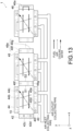
- FIG. 13 is a schematic diagram showing a configuration of a fuel cell 1 according to a second embodiment.
- the second embodiment is different from the first embodiment in that the fuel electrode gas in place of the oxidant gas passes through so as to penetrate a plurality of cell stacked bodies 10. Accordingly, the fuel electrode gas passes through fifth manifolds 48.
- the cooling water does not pass through the fifth manifolds 48 but is fed for each of the cell stacked bodies 10.
- collecting pipes for the cooling water are omitted. Nevertheless, an inlet collecting pipe for the cooling water is connected to a piping joint part 40a of each of the cell stacked bodies 10, for example. An outlet collecting pipe for the cooling water is connected to a piping joint part 44a of each of the cell stacked bodies 10, for example.
- the cell stacked bodies 10 are arranged to line up in the first direction perpendicular to the stacking direction.
- the first direction in the second embodiment is the X-direction in the example shown in Figure 13 .
- the cell stacked bodies 10 are arranged such that their orientations in the Z-direction are the same as those of the adjacent cell stacked bodies 10.
- the plurality of cell stacked bodies 10 are electrically connected in parallel as shown in Figure 12 .
- the cell stacked bodies 10 may be arranged such that their orientations in the Z-direction are reverse to those of the adjacent cell stacked bodies 10.
- the cell stacked bodies 10 are arranged so as to rotate relative to the adjacent cell stacked bodies 10 by 180° around the Y-direction, for example. Moreover, in this case, the plurality of cell stacked bodies 10 are electrically connected in series as shown in Figure 11 .
- the fifth manifolds 48 are provided between the cell stacked bodies 10 arranged to line up in the first direction (X-direction). As shown in Figure 13 , for the cell stacked body 10 that is at one end in the first direction, the fifth manifold and the second manifold 42 are respectively arranged on opposite sides of the lateral surfaces of the cell stacked body 10. Moreover, for the cell stacked body 10 that is at the other end in the first direction, the fifth manifold and the fourth manifold 46 are respectively arranged on opposite sides of the lateral surfaces of the cell stacked body 10.
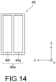
- Figure 14 is a schematic diagram showing a configuration of the fifth manifold 48 according to the second embodiment.
- Figure 14 is a schematic diagram showing a shape of the fifth manifold 48 as horizontally viewed from the side of the cell stacked body 10 that the second manifold 42 is provided on.
- the fifth manifold 48 includes a fuel electrode manifold. Notably, a cooling water manifold is not provided in the fifth manifold 48 according to the second embodiment.
- the fuel electrode manifold of the fifth manifold 48 includes a gas flow channel part 48e.
- a shape of the gas flow channel part 48e may be similar to the shape of the gas flow channel part 48a according to the first embodiment in Figure 8C .
- the gas flow channel part 48e includes a first flow channel part 48f and a second flow channel part 48g.
- the first flow channel part 48f allows communication between the third region in the cell stacked body 10 and the third region in the adjacent cell stacked body 10. More in detail, the first flow channel part 48f allows communication between the third region of fuel electrode gas flow channel grooves 140b in the cell stacked body 10 and the third region of the fuel electrode gas flow channel grooves 140b in the adjacent cell stacked body 10.
- the second flow channel part 48g allows communication between the fourth region in the cell stacked body 10 and the fourth region in the adjacent cell stacked body. More in detail, the second flow channel part 48g allows communication between the fourth region of the fuel electrode gas flow channel grooves 140b in the cell stacked body 10 and the fourth region of the fuel electrode gas flow channel grooves 140b in the adjacent cell stacked body 10. Notably, a partition is provided between the first flow channel part 48f and the second flow channel part 48g.
- relationship between the oxidant gas and the fuel electrode gas is approximately reverse to that in the first embodiment.
- the third region and the fourth region according to the second embodiment correspond to the first region and the second region according to the first embodiment, respectively.
- an opening area of the first flow channel part 48f is larger than an opening area of the second flow channel part 48g. Accordingly, a reaction efficiency of the fuel electrode reaction on the fuel electrodes is equalized more in the fuel electrode flow channels. Nevertheless, not limitedly, the opening area of the first flow channel part 48f may be substantially the same as the opening area of the second flow channel part 48g.
- the other configuration of the fuel cell 1 according to the second embodiment is similar to the corresponding configuration of the fuel cell 1 according to the first embodiment, and its detailed description is omitted.
- the fuel cell 1 according to the second embodiment can attain the effects similar to those for the first embodiment.
Landscapes
- Life Sciences & Earth Sciences (AREA)
- Engineering & Computer Science (AREA)
- Manufacturing & Machinery (AREA)
- Sustainable Development (AREA)
- Sustainable Energy (AREA)
- Chemical & Material Sciences (AREA)
- Chemical Kinetics & Catalysis (AREA)
- Electrochemistry (AREA)
- General Chemical & Material Sciences (AREA)
- Fuel Cell (AREA)
Abstract
Description
- Embodiments according to the present invention relate to a fuel cell and a manifold for a fuel cell.
- A fuel cell is a power generation device which, via chemical reaction of fuel such as hydrogen and oxidant such as air, directly converts the fuel's chemical energy into electric energy and take this converted energy to the outside. In an external manifold scheme, gas manifolds for feeding a fuel gas, an oxidant gas and the like are provided on the exterior of a stacked body of unit cells (elements).
- In the case of the external manifold scheme, however, it is occasionally difficult to increase/decrease (change) output of the fuel cell in accordance with its application.
- [Patent Literature 1]
Japanese Patent No. 3425086 - Therefore, an object of an embodiment of the present invention is to provide a fuel cell and a manifold for a fuel cell capable of more easily modifying output of the fuel cell in an external manifold scheme.
- A fuel cell according to the present embodiment includes a cell stacked body and a manifold. The cell stacked body has elements stacked, each element having: an electrolyte membrane; a fuel electrode and an oxidant electrode between which the electrolyte membrane is interposed; a fuel electrode flow channel plate in which a gas flow channel facing the fuel electrode is provided; and an oxidant electrode flow channel plate in which a gas flow channel facing the oxidant electrode is provided. The manifold is provided on a lateral surface, of the cell stacked body, along a stacking direction of the cell stacked body and feeds a reaction gas to the fuel electrode flow channel plate or the oxidant electrode flow channel plate in the cell stacked body. The manifold includes a gas flow channel part that is provided between a plurality of the cell stacked bodies arranged to line up in a first direction perpendicular to the stacking direction and that allows communication between the cell stacked bodies such that the reaction gas passes through.
-
- [
Figure 1] Figure 1 is a perspective view showing an example of a structure of a fuel cell having manifolds taken off. - [
Figure 2] Figure 2 is a perspective view showing an example of a structure of the fuel cell in the state where the manifolds are mounted. - [
Figure 3] Figure 3 is an exploded perspective view showing an example of a configuration of a fuel cell element. - [
Figure 4] Figure 4 shows views showing an example of a configuration of a fuel electrode flow channel plate. - [
Figure 5] Figure 5 shows views showing an example of a configuration of an oxidant electrode flow channel plate. - [
Figure 6] Figure 6 is a view showing an example of a configuration of a front side of a fastening plate and a configuration of a terminal. - [
Figure 7] Figure 7 is a schematic diagram showing a configuration of a fuel cell according to a first embodiment. - [
Figure 8] Figure 8 shows schematic diagrams showing configurations of a first manifold, a third manifold, and a fifth manifold according to the first embodiment. - [
Figure 9] Figure 9 shows schematic diagrams showing configurations of a second manifold and a fourth manifold according to the first embodiment. - [
Figure 10] Figure 10 is a schematic diagram showing arrangement and electric connection of cell stacked bodies according to the first embodiment. - [
Figure 11] Figure 11 is a schematic diagram showing arrangement and electric connection of cell stacked bodies according to a modification. - [
Figure 12] Figure 12 is a schematic diagram showing a configuration of a fuel cell according to a modification. - [
Figure 13] Figure 13 is a schematic diagram showing a configuration of a fuel cell according to a second embodiment. - [
Figure 14] Figure 14 is a schematic diagram showing a configuration of a fifth manifold according to the second embodiment. - Hereafter, embodiments according to the present invention will be described with reference to the drawings. These embodiments do not limit the present invention. The drawings are schematic or conceptual, and ratios between the individual portions therein and the like are not necessarily identical to the real ones. In the description and the drawings, the similar elements to those having been described regarding the drawings having already been mentioned are given the same signs, and their detailed description is properly omitted.
-
Figure 1 is a perspective view showing an example of a structure of afuel cell 1 having manifolds taken off.Figure 2 is a perspective view showing an example of a structure of thefuel cell 1 in the state where the manifolds are mounted. As shown inFigure 1 andFigure 2 , thefuel cell 1 according to a first embodiment is a structure body which generates electric power via electrochemical reaction in fuel cell elements. Namely, thefuel cell 1 is configured to include a cell stackedbody 10, twocurrent collector plates 20, twoinsulating plates 25, a fuel cellfastening structure body 30, afirst manifold 40, asecond manifold 42, athird manifold 44, and afourth manifold 46. The cell stackedbody 10 has a plurality offuel cell elements 10a stacked. Eachfuel cell element 10a generates electric power via electrochemical reaction of a fuel electrode gas containing hydrogen and an oxidant electrode gas containing oxygen. Namely, the cell stackedbody 10 is a structure body in which the plurality offuel cell elements 10a are connected in series. A detailed configuration of thefuel cell element 10a is mentioned later.Figure 1 andFigure 2 each show a Z-direction parallel to a stacking direction of the cell stackedbody 10, and an X-direction and a Y-direction which are perpendicular to the Z-direction and parallel to each other. When thefuel cell 1 of the present embodiment is installed on a horizontal plane, the Z-direction is parallel to the direction of gravity. - The two
current collector plates 20 are arranged on both sides of the cell stackedbody 10 in the stacking direction. The twocurrent collector plates 20 are plate-like conductors, and are respectively arranged on both end faces of the cell stackedbody 10. The twoinsulating plates 25 are plate-like insulators, and are respectively arranged between the twocurrent collector plates 20 and the twofastening plates 100. As above, the twocurrent collector plates 20 and the twoinsulating plates 25 are sequentially arranged on both sides of the cell stackedbody 10 in the stacking direction, and integrally fastening these from both sides in the stacking direction with the twofastening plates 100 affords thefuel cell 1. - The fuel cell
fastening structure body 30 is a structure body which exerts surface pressure onto the cell stackedbody 10, and is configured to include the twofastening plates 100 and a plurality ofcoupling members 200. The twofastening plates 100 are members which fasten the cell stackedbody 10 from both sides, in the stacking direction, of the cell stackedbody 10 having a plurality of fuel cell elements stacked. Eachfastening plate 100 has apressing part 110 andbeam parts 120. Thesepressing part 110 andbeam parts 120 are integrally formed. Notably, thepressing part 110 and thebeam parts 120 may be separately configured. - The
coupling members 200 are members which couple the twofastening plates 100. Namely, eachcoupling member 200 according to the present embodiment has atie rod 202, twowashers 204, and twonuts 206. As shown inFigure 1 , the twofastening plates 100 are coupled by thenuts 206 fastened via thewashers 204 in the state where thetie rods 202 are inserted through respective opposing hole parts provided in the twofastening plates 100. - As shown in
Figure 2 , themanifolds body 10 along the stacking direction of the cell stackedbody 10 in thefuel cell 1. The manifolds are members including spatial regions for feeding reaction gases such as the fuel electrode gas and the oxidant electrode gas, cooling water, and the like. - The
first manifold 40 has a cooling water manifold and an oxidant electrode manifold. Thesecond manifold 42 is a fuel electrode manifold. Thethird manifold 44 is a manifold opposite to thefirst manifold 40, and has a cooling water manifold and an oxidant electrode manifold. Namely, thefirst manifold 40 and thethird manifold 44 are respectively arranged on opposite sides of the lateral surfaces of the cell stackedbody 10. - The
fourth manifold 46 is a manifold opposite to thesecond manifold 42, and is a fuel electrode manifold. Namely, thesecond manifold 42 and thefourth manifold 46 are respectively arranged on opposite sides of the lateral surfaces of the cell stackedbody 10. - Cooling water introduced from a piping
joint part 40a is fed from the lateral surface of the cell stackedbody 10 and is discharged from a pipingjoint part 44a via cooling water flow channel grooves of eachfuel cell element 10a. Meanwhile, the oxidant electrode gas is introduced from a pipingjoint part 40b, and the oxidant electrode gas that is not consumed by the electrochemical reaction in the cell stackedbody 10 is discharged from a pipingjoint part 40c. Moreover, the fuel electrode gas is introduced from a pipingjoint part 42a, and the fuel electrode gas that is not consumed by the electrochemical reaction in the cell stackedbody 10 is discharged from a pipingjoint part 42b. - Gas impermeability is required for the
manifolds manifolds - Detailed configuration of the
fuel cell element 10a according to the first embodiment is described based onFigure 3 to Figure 5 .Figure 3 is an exploded perspective view showing an example of a configuration of a fuel cell element. As shown inFigure 3 , thefuel cell element 10a is configured to include an electrolyte membrane 12, a fuel electrodeflow channel plate 14, and an oxidant electrodeflow channel plate 16. This electrolyte membrane 12 has a fuel electrode formed on oneprincipal plane 12a and an oxidant electrode formed on the otherprincipal plane 12b. Namely, thefuel cell element 10a includes the fuel electrode and the oxidant electrode provided such that the electrolyte membrane 12 is interposed (sandwiched) therebetween. The electrolyte membrane 12 is a polymer electrolyte membrane, for example. -
Figure 4 shows views showing an example of a configuration of the fuel electrodeflow channel plate 14,Figure 4A is a view showing a shape of aprincipal plane 14a side of the fuel electrodeflow channel plate 14, andFigure 4B is a view showing a shape of aprincipal plane 14b side of the fuel electrodeflow channel plate 14. As shown in thisFigure 4A , theprincipal plane 14a of the fuel electrodeflow channel plate 14 is on the opposite side to the fuel electrode of the electrolyte membrane 12, and forms a flat surface. - As shown in
Figure 4B , the fuel electrodeflow channel plate 14 has, on theprincipal plane 14b on the fuel electrode side of the electrolyte membrane 12, fuel electrode gasflow channel grooves 140b provided along the fuel electrode. Moreover, the fuel electrode gasflow channel grooves 140b have afirst inlet part 14c, afirst outlet part 14d, asecond inlet part 14e, and asecond outlet part 14f. The fuel electrode gas introduced from thefirst inlet part 14c flows along the fuel electrode gasflow channel grooves 140b and is discharged from thefirst outlet part 14d. Moreover, the fuel electrode gas introduced from thesecond inlet part 14e flows along the fuel electrode gasflow channel grooves 140b and is discharged from thesecond outlet part 14f. -
Figure 5 shows views showing an example of a configuration of the oxidant electrodeflow channel plate 16,Figure 5A is a view showing a shape of aprincipal plane 16a of the oxidant electrodeflow channel plate 16, andFigure 5B is a view showing a shape of aprincipal plane 16b on the opposite side to theprincipal plane 16a of the oxidant electrodeflow channel plate 16. As shown in thisFigure 5A , the oxidant electrodeflow channel plate 16 has, on theprincipal plane 16a on the oxidant electrode side of the electrolyte membrane 12, oxidant gasflow channel grooves 160a provided along the oxidant electrode. Moreover, the oxidant gasflow channel grooves 160a have afirst inlet part 16c, afirst outlet part 16d, asecond inlet part 16e, and asecond outlet part 16f. An oxidant gas introduced from thefirst inlet part 16c flows along the oxidant gasflow channel grooves 160a and is discharged from thefirst outlet part 16d. Moreover, the oxidant gas introduced from thesecond inlet part 16e flows along the oxidant gasflow channel grooves 160a and is discharged from thesecond outlet part 16f. - As shown in
Figure 5B , in the oxidant electrodeflow channel plate 16, cooling waterflow channel grooves 160b are provided on theprincipal plane 16b on the opposite side to the oxidant electrode side. The cooling waterflow channel grooves 160b have afirst inlet part 16h and afirst outlet part 16g. The cooling water introduced from thefirst inlet part 16h flows along the cooling waterflow channel grooves 160b and is discharged from thefirst outlet part 16g. The oxidant electrodeflow channel plate 16 is configured of a conductive porous plate having micropores, for example. Moreover, the cooling waterflow channel grooves 160b vaporize the cooling water from their surfaces to humidify thefuel cell element 10a. Notably, the oxidant electrodeflow channel plate 16 that does not have the cooling waterflow channel grooves 160b may be used. When using the oxidant electrodeflow channel plate 16 not having the cooling waterflow channel grooves 160b, thefirst manifold 40 and thethird manifold 44 may be configured only of oxidant electrode manifolds. - The plurality of these
fuel cell elements 10a generate electric power via reaction expressed bychemical formula 1. More in detail, the fuel electrode gas is a hydrogen-containing gas, for example. The fuel electrode gas flows along the fuel electrode gasflow channel grooves 140b of the fuel electrodeflow channel plate 14 and causes a fuel electrode reaction to occur. The oxidant gas is an oxygen-containing gas, for example. The oxidant gas flows along the oxidant gasflow channel grooves 160a of the oxidant electrodeflow channel plate 16 and causes an oxidant electrode reaction to occur. Using these electrochemical reactions, thefuel cell 1 takes out electric energy from electrodes provided on the current collector plates 20 (Figure 1 ).
(Chemical Formula 1) Fuel electrode reaction: H2 → 2H+ + 2e-Oxidant electrode reaction: 1/2O2 + 2H+ + 2e- → H2O
-
Figure 6 is a view showing an example of a configuration of the front side of thefastening plate 100 and a configuration of a terminal 300. As shown in thisFigure 6 , thefastening plate 100 has the terminal 300 and aterminal cover 310 mounted. This terminal 300 is electrically connected to thecurrent collector plate 20. Notably, a terminal 300 is also provided on the lower side in the stacking direction, not only on the upper side in the stacking direction. The twoterminals 300 provided at both ends in the stacking direction are a positive electrode terminal and a negative electrode terminal, for example. Notably, details of theterminals 300 are described later with reference toFigure 10 . -
Figure 7 is a schematic diagram showing a configuration of thefuel cell 1 according to the first embodiment. Notably, inFigure 7 , circles shown on themanifolds joint parts Figure 2 . Moreover,Figure 7 shows collecting pipes for the fuel electrode gas. The collecting pipes for the fuel electrode gas are connected to the pipingjoint parts Figure 2 . Notably,Figure 7 does not show the fuel cellfastening structure body 30 shown inFigure 1 andFigure 2 . The cell stackedbodies 10 may be provided with distances between the cell stackedbodies 10 wide enough, for example, such that thecoupling members 200 can be provided therebetween. - In addition to the
aforementioned manifolds fuel cell 1 further includesfifth manifolds 48. Themanifolds flow channel plates 14 in the cell stackedbodies 10, and feed the oxidant gas and the cooling water to the oxidant electrodeflow channel plates 16 therein. - The plurality of cell stacked
bodies 10 are arranged to line up in a first direction perpendicular to the stacking direction. In the example shown inFigure 7 , the first direction is the Y-direction. Moreover, in the first embodiment, the cell stackedbodies 10 are arranged such that the orientation of each of them in the Z-direction is reverse to that of adjacent one of the cell stackedbodies 10. The cell stackedbodies 10 are arranged such that each of them rotates relative to adjacent one of the cell stackedbodies 10 by 180° around the Y-direction. - The
fifth manifolds 48 are provided between the cell stackedbodies 10 arranged to line up in the first direction (Y-direction). As shown inFigure 7 , for the cell stackedbody 10 that is at one end in the first direction, the fifth manifold and thefirst manifold 40 are arranged on the respective opposite lateral surfaces of the cell stackedbody 10. Moreover, for the cell stackedbody 10 that is at the other end in the first direction, the fifth manifold and thethird manifold 44 are arranged on the respective opposite lateral surfaces of the cell stackedbody 10. - First, configurations of the
first manifold 40, thethird manifold 44, and thefifth manifold 48 are described with reference toFigure 7 andFigure 8A to Figure 8C . -
Figure 8 shows schematic diagrams showing configurations of thefirst manifold 40, thethird manifold 44, and thefifth manifold 48 according to the first embodiment.Figure 8A is a schematic diagram showing a shape of thefirst manifold 40 as horizontally viewed from the cell stackedbody 10 side,Figure 8B is a schematic diagram showing a shape of thethird manifold 44 as horizontally viewed from the cell stackedbody 10 side, andFigure 8C is a schematic diagram showing a shape of thefifth manifold 48 as horizontally viewed from the side of the cell stackedbody 10 that thefirst manifold 40 is provided on. - As shown in
Figure 8A , thefirst manifold 40 includes the oxidant manifold which feeds the oxidant gas, and the cooling water manifold which feeds the cooling water. The oxidant manifold of thefirst manifold 40 includes the pipingjoint part 40b, the pipingjoint part 40c, agas introducing part 40d, and agas discharging part 40e. The cooling water manifold of thefirst manifold 40 includes the pipingjoint part 40a and a coolingwater introducing part 40f. - The piping
joint part 40a is a joint part for feeding and communicates with the coolingwater introducing part 40f. This pipingjoint part 40a feeds the cooling water to the coolingwater introducing part 40f. - The piping
joint part 40b is a joint part for feeding and communicates with thegas introducing part 40d. This pipingjoint part 40b feeds the reaction gas (oxidant gas) to thegas introducing part 40d. - The piping
joint part 40c is a joint part for discharging and communicates with thegas discharging part 40e. This pipingjoint part 40c discharges an unreacted gas which is not consumed by the electrochemical reaction from thegas discharging part 40e. - The
gas introducing part 40d, thegas discharging part 40e, and the coolingwater introducing part 40f are a plurality of spatial region parts arranged along the lateral surface of the cell stackedbody 10 along the cell stacking direction. Notably, thegas introducing part 40d, thegas discharging part 40e, and the coolingwater introducing part 40f do not communicate (penetrate) in the Y-direction. - Notably, an area where the
gas introducing part 40d is in contact with the lateral surface of the cell stackedbody 10 is wider than an area where thegas discharging part 40e is in contact with the lateral surface of the cell stackedbody 10. The oxidant gas is consumed by the electrochemical reaction more at thegas discharging part 40e than at thegas introducing part 40d. Accordingly, since as the amount of oxygen contained in the oxidant gas becomes smaller at thegas discharging part 40e, an area in contact with the oxidant electrodes becomes smaller, a reaction efficiency of the oxidant electrode reaction on the oxidant electrodes is equalized more in the oxidant electrode flow channels. Nevertheless, not limitedly, the area where thegas introducing part 40d is in contact with the lateral surface of the cell stackedbody 10 may be substantially the same as the area where thegas discharging part 40e is in contact with the lateral surface of the cell stackedbody 10. - As shown in
Figure 8B , thethird manifold 44 includes the oxidant manifold which feeds the oxidant gas, and the cooling water manifold which feeds the cooling water. The oxidant manifold of thethird manifold 44 includes agas passing part 44b. The cooling water manifold of thethird manifold 44 includes the pipingjoint part 44a and a coolingwater discharging part 44c. - The piping
joint part 44a is a joint part for discharging and communicates with the coolingwater discharging part 44c. This pipingjoint part 44a discharges the cooling water from the coolingwater discharging part 44c. - The
gas passing part 44b and the coolingwater discharging part 44c are a plurality of spatial region parts arranged along the lateral surface of the cell stackedbody 10 along the cell stacking direction. Notably, thegas passing part 44b and the coolingwater discharging part 44c do not communicate (penetrate) in the Y-direction. - As shown in
Figure 8C , thefifth manifold 48 includes an oxidant manifold which feeds the oxidant gas, and a cooling water manifold which feeds the cooling water. The oxidant manifold of thefifth manifold 48 includes a gasflow channel part 48a. The cooling water manifold of thefifth manifold 48 includes a cooling waterflow channel part 48d. - The gas
flow channel part 48a and the cooling waterflow channel part 48d are a plurality of spatial region parts arranged along the lateral surface of the cell stackedbody 10 along the cell stacking direction. Notably, the gasflow channel part 48a (a firstflow channel part 48b and a secondflow channel part 48c) and the cooling waterflow channel part 48d communicate (penetrate) in the Y-direction. - Notably, a fifth manifold that is rotated by 180° around the Y-direction is provided on adjacent one of the cell stacked bodies 10 (refer to
Figure 7 ). Namely, the shapes (types) of thefifth manifolds 48 may be the same. - As shown in
Figure 7 , thegas introducing part 40d is provided, for the cell stackedbody 10 that is at one end in the first direction, on the lateral surface that is on the opposite side to the gasflow channel part 48a (fifth manifold 48). Moreover, thegas introducing part 40d introduces the reaction gas (oxidant gas) into the cell stackedbody 10. More in detail, thegas introducing part 40d introduces the oxidant gas into a first region of the oxidant gasflow channel grooves 160a in the cell stackedbody 10. For example, the first region is a region of the oxidant gasflow channel grooves 160a between thefirst inlet part 16c (Figure 5A ) and thefirst outlet part 16d (Figure 5A ). - The
gas discharging part 40e is provided on at least part of the lateral surface that thegas introducing part 40d is provided on. Moreover, thegas discharging part 40e discharges the reaction gas (oxidant gas) from the inside of the cell stackedbody 10. More in detail, thegas discharging part 40e discharges the oxidant gas from a second region of the oxidant gasflow channel grooves 160a in the cell stackedbody 10. For example, the second region is a region of the oxidant gasflow channel grooves 160a between thesecond inlet part 16e (Figure 5A ) and thesecond outlet part 16f (Figure 5A ). - The cooling
water introducing part 40f is provided, for the cell stackedbody 10 that is at the one end in the first direction, on the lateral surface that is on the opposite side to the gasflow channel part 48a (fifth manifold 48). Moreover, the coolingwater introducing part 40f introduces the cooling water into the cell stackedbody 10. - The
gas passing part 44b is provided, for the cell stackedbody 10 that is at the other end in the first direction, on the lateral surface that is on the opposite side to the gasflow channel part 48a (fifth manifold 48). Moreover, thegas passing part 44b allows communication between the first region in the cell stackedbody 10 and the second region, in the cell stackedbody 10, different from the relevant first region such that the reaction gas (oxidant gas) passes through. More in detail, thegas passing part 44b allows communication between the first region of the oxidant gasflow channel grooves 160a in the cell stackedbody 10 and the second region of the oxidant gasflow channel grooves 160a in the cell stackedbody 10. - The cooling
water discharging part 44c is provided, for the cell stackedbody 10 that is at the other end in the first direction, on the lateral surface that is on the opposite side to the gasflow channel part 48a (fifth manifold 48). Moreover, the coolingwater discharging part 44c discharges the cooling water from the inside of the cell stackedbody 10. - The gas
flow channel parts 48a are provided between the plurality of cell stackedbodies 10 arranged to line up in the first direction perpendicular to the stacking direction. More in detail, each gasflow channel part 48a is provided between a first lateral surface S1 of a cell stackedbody 10 and a second lateral surface S2, of an adjacent cell stackedbody 10, that faces the first lateral surface S1. Moreover, the gasflow channel parts 48a allow communication between the cell stackedbodies 10 such that the reaction gas (oxidant gas) passes through. Accordingly, the oxidant gas passes through so as to penetrate the plurality of cell stackedbodies 10 via the gasflow channel parts 48a. Thereby, the number of connection of cell stackedbodies 10 can be more easily modified in accordance with desired output of thefuel cell 1. Consequently, the output of thefuel cell 1 in the external manifold scheme can be more easily modified. - Moreover, more in detail, each gas
flow channel part 48a has the firstflow channel part 48b and the secondflow channel part 48c. - The first
flow channel part 48b allows communication between the first region in the cell stackedbody 10 and the first region in the adjacent cell stackedbody 10. More in detail, the firstflow channel part 48b allows communication between the first region of the oxidant gasflow channel grooves 160a in the cell stackedbody 10 and the first region of the oxidant gasflow channel grooves 160a in the adjacent cell stackedbody 10. - Notably, as shown in
Figure 7 , the flow channels for the oxidant gas are not the same in the adjacent cell stackedbodies 10. This is because the cell stackedbody 10 is arranged relative to the adjacent cell stackedbody 10 such that the orientations of those in the Z-direction are reverse to each other. Namely, for example, inFigure 5A , the oxidant gas advances along the oxidant gasflow channel grooves 160a which are rotated by 180° around the Y-direction. Accordingly, in the adjacent cell stackedbody 10, the first region is a region of the oxidant gasflow channel grooves 160a between thesecond outlet part 16f (Figure 5A ) and thesecond inlet part 16e (Figure 5A ), for example. Likewise, in the adjacent cell stackedbody 10, the second region is a region of the oxidant gasflow channel grooves 160a between thefirst outlet part 16d (Figure 5A ) and thefirst inlet part 16c (Figure 5A ), for example. - The second
flow channel part 48c allows communication between the second region in the cell stackedbody 10 and the second region in the adjacent cell stacked body. More in detail, the secondflow channel part 48c allows communication between the second region of the oxidant gasflow channel grooves 160a in the cell stackedbody 10 and the second region of the oxidant gasflow channel grooves 160a in the adjacent cell stackedbody 10. Notably, a partition is provided between the firstflow channel part 48b and the secondflow channel part 48c. - The cooling water
flow channel parts 48d are provided between the plurality of cell stackedbodies 10 arranged to line up in the first direction. Moreover, the cooling waterflow channel parts 48d allows communication between the cell stackedbodies 10 such that the cooling water passes through. - Next, flows of the reaction gas (oxidant gas) are described with reference to
Figure 7 . - In the example shown in
Figure 7 , the oxidant gas (air) is fed to thegas introducing part 40d via the pipingjoint part 40b. The oxidant gas flows in the oxidant gasflow channel grooves 160a via thefirst inlet parts 16c (Figure 5A ) of the oxidant electrodeflow channel plates 16 that communicate with thegas introducing part 40d among the oxidant electrodeflow channel plates 16 stacked in the cell stackedbody 10, and is discharged from thefirst outlet parts 16d (Figure 5A ) to the firstflow channel part 48b of thefifth manifold 48. The oxidant gas having been discharged to the firstflow channel part 48b flows likewise in the oxidant gasflow channel grooves 160a of the oxidant electrodeflow channel plates 16, also in the adjacent cell stackedbody 10. After that, the oxidant gas is discharged to thegas passing part 44b of thethird manifold 44. The oxidant gas having been discharged to thegas passing part 44b flows in oxidant gasflow channel grooves 160a (Figure 5A ) via thesecond inlet parts 16e (Figure 5A ) of the oxidant electrodeflow channel plates 16 that communicate with thegas passing part 44b among the oxidant electrodeflow channel plates 16 stacked in the cell stackedbody 10, and is discharged from thesecond outlet parts 16f (Figure 5A ) to the secondflow channel part 48c of thefifth manifold 48. The oxidant gas having been discharged to the secondflow channel part 48c passes likewise through the oxidant electrodeflow channel plates 16, also in the adjacent cell stackedbody 10. After that, the oxidant gas is discharged to thegas discharging part 40e of thefirst manifold 40. The oxidant gas having been discharged to thegas discharging part 40e is discharged from the pipingjoint part 40c communicating with thegas discharging part 40e. - As above, the oxidant gas flows in the oxidant gas
flow channel grooves 160a of the oxidant electrodeflow channel plates 16 in the cell stackedbodies 10, and thereby, the oxidant gas is fed to the oxidant electrodes of the electrolyte membranes 12. Meanwhile, the oxidant gas is consumed by the electrochemical reaction. Accordingly, a flow rate of the oxidant gas only has to be made larger as the number of cell stackedbodies 10 which the oxidant gas passes through is larger. - Next, flows of the cooling water are described with reference to
Figure 7 . - In the example shown in
Figure 7 , the cooling water is stored in the coolingwater introducing part 40f via the pipingjoint part 40a. The cooling water flows in the cooling waterflow channel grooves 160b via thefirst inlet parts 16h (Figure 5B ) of the oxidant electrodeflow channel plates 16 that communicate with the coolingwater introducing part 40f, and is discharged from thefirst outlet parts 16g (Figure 5B ) to the cooling waterflow channel part 48d of thefifth manifold 48. The cooling water having been discharged to the cooling waterflow channel part 48d flows likewise in the cooling waterflow channel grooves 160b of the oxidant electrodeflow channel plates 16, also in the adjacent cell stackedbody 10. After that, the cooling water is discharged to the coolingwater discharging part 44c of thethird manifold 44. The cooling water stored in the coolingwater discharging part 44c is discharged from the pipingjoint part 44a communicating with the coolingwater discharging part 44c. As above, the cooling water flows in the cooling waterflow channel grooves 160b of the oxidant electrodeflow channel plates 16 in the cell stackedbodies 10, and thereby, the cell stackedbodies 10 are cooled. - Next, configurations of the
second manifold 42 and thefourth manifold 46 are described with reference toFigure 7 andFigure 9A to Figure 9B . -
Figure 9 shows schematic diagrams showing configurations of thesecond manifold 42 and thefourth manifold 46 according to the first embodiment.Figure 9A is a schematic diagram showing a shape of thesecond manifold 42 as horizontally viewed from the cell stackedbody 10 side, andFigure 9B is a schematic diagram showing a shape of thefourth manifold 46 as horizontally viewed from the cell stackedbody 10 side. - As shown in
Figure 9A , thesecond manifold 42 includes the fuel electrode manifold which feeds the fuel electrode gas. The fuel electrode manifold of thesecond manifold 42 includes the pipingjoint part 42a, the pipingjoint part 42b, agas introducing part 42c, and agas discharging part 42d. - The piping
joint part 42a is a joint part for feeding and communicates with thegas introducing part 42c. This pipingjoint part 42a feed the reaction gas to thegas introducing part 42c. - The piping
joint part 42b is a joint part for discharging and communicates with thegas discharging part 42d. This pipingjoint part 42b discharges an unreacted gas which is not consumed by the electrochemical reaction from thegas discharging part 42d. - The
gas introducing part 42c and thegas discharging part 42d are a plurality of spatial region parts arranged along the lateral surface of the cell stackedbody 10 along the cell stacking direction. - As shown in
Figure 9B , thefourth manifold 46 includes the fuel electrode manifold which feeds the fuel electrode gas. The fuel electrode manifold of thefourth manifold 46 includes agas passing part 46a. - The
gas passing part 46a is a spatial region part arranged along the lateral surface of the cell stackedbody 10 along the cell stacking direction. - As shown in
Figure 7 , thegas introducing part 42c is provided on the lateral surface, of the cell stackedbody 10, that is on the opposite side to thegas passing part 46a (fourth manifold 46). Moreover, thegas introducing part 42c introduces the oxidant gas into the cell stackedbody 10. More in detail, thegas introducing part 42c introduces the fuel electrode gas to a third region of the fuel electrode gasflow channel grooves 140b in the cell stackedbody 10. For example, the third region is a region of the fuel electrode gasflow channel grooves 140b between thefirst inlet part 14c (Figure 4B ) and thefirst outlet part 14d (Figure 4B ). - The
gas discharging part 42d is provided on at least part of the lateral surface that thegas introducing part 42c is provided on. Moreover, thegas discharging part 42d discharges the fuel electrode gas from the cell stackedbody 10. More in detail, thegas discharging part 42d discharges the fuel electrode gas from a fourth region of the fuel electrode gasflow channel grooves 140b in the cell stackedbody 10. For example, the fourth region is a region of the fuel electrode gasflow channel grooves 140b between thesecond inlet part 14e (Figure 4B ) and thesecond outlet part 14f (Figure 4B ). - The
gas passing part 46a is provided, for the cell stackedbody 10, on the lateral surface that is on the opposite side to thegas introducing part 42c (second manifold 42). Moreover, thegas passing part 46a allows communication between the third region in the cell stackedbody 10 and the fourth region, in the cell stackedbody 10, different from the relevant third region such that the fuel electrode gas passes through. More in detail, thegas passing part 46a allows communication between the third region of the fuel electrode gasflow channel grooves 140b in the cell stackedbody 10 and the fourth region of the fuel electrode gasflow channel grooves 140b in the cell stackedbody 10. - Next, flows of the reaction gas (fuel electrode gas) are described with reference to
Figure 7 . - In the example shown in
Figure 7 , the fuel electrode gas (fuel) is fed to thegas introducing part 42c via the pipingjoint part 42a. The fuel electrode gas flows in the fuel electrode gasflow channel grooves 140b (Figure 4B ) via thefirst inlet parts 14c of the fuel electrodeflow channel plates 14 that communicate with thegas introducing part 42c among the fuel electrodeflow channel plates 14 stacked in the cell stackedbody 10, and is discharged from thefirst outlet parts 14d (Figure 4B ) to thegas passing part 46a of thefourth manifold 46. The fuel electrode gas having been discharged to thegas passing part 46a flows in the fuel electrode gasflow channel grooves 140b (Figure 4B ) via thesecond inlet parts 14e (Figure 4B ) of the fuel electrodeflow channel plates 14 that communicate with thegas passing part 46a among the fuel electrodeflow channel plates 14 stacked in the cell stackedbody 10, and is discharged from thesecond outlet parts 14f (Figure 4B ) to thegas discharging part 42d of thesecond manifold 42. The fuel electrode gas having been discharged to thegas discharging part 42d is discharged from the pipingjoint part 42b communicating with thegas discharging part 42d. - As above, the fuel electrode gas flows in the fuel electrode gas
flow channel grooves 140b of the fuel electrodeflow channel plates 14 in the cell stackedbodies 10, and thereby, the fuel electrode gas is fed to the fuel electrodes of the electrolyte membranes 12. -
Figure 10 is a schematic diagram showing arrangement and electric connection of the cell stackedbodies 10 according to the first embodiment. Notably, inFigure 10 , theterminals 300 described with reference toFigure 6 , that is, the positive electrode terminals and the negative electrode terminals are omitted. Thefastening plates 100 that are denoted with + signs are thefastening plates 100 on the positive electrode terminal sides. Thefastening plates 100 that are denoted with - signs are thefastening plates 100 on the negative electrode terminal sides. - The
fuel cell 1 further includes the positive electrode terminals, the negative electrode terminals, andelectrode connecting parts 401. - The cell stacked
bodies 10 are arranged to line up such that the orientations of the positive electrode terminal and the negative electrode terminal of each of them are reverse to those of adjacent one of the cell stackedbodies 10. - The positive electrode terminals and the negative electrode terminals are provided in both end parts of the cell stacked
bodies 10 in the stacking direction, and are electrically connected to the cell stacked bodies 10 (current collector plates 20). - The
electrode connecting parts 401 electrically connect the positive electrode terminals and the negative electrode terminals of the adjacent cell stackedbodies 10 so as to connect the plurality of cell stackedbodies 10 electrically in series. Theelectrode connecting parts 401 are conductors such, for example, as bus bars. Connecting the plurality of cell stackedbodies 10 in series can afford high voltage. Thereby, current can be restrained from rising, and losses in electric power can be reduced. Consequently, efficiency in an electricity system can be improved. Moreover, since the orientations of the positive electrode terminal and the negative electrode terminal are reverse to those of the adjacent cell stackedbodies 10, theelectrode connecting parts 401 as wiring can be shortened. Consequently, losses in electric power due to theelectrode connecting parts 401 can be reduced, and the volume of thefuel cell 1 can be reduced. Furthermore, the shapes of theelectrode connecting parts 401 can be of one type, and the number of types of components can be reduced. - As above, according to the first embodiment, the
fifth manifolds 48 are provided between the cell stackedbodies 10 arranged to line up in the first direction perpendicular to the stacking direction, and include the gasflow channel parts 48a allowing communication between the cell stackedbodies 10 such that the reaction gas (oxidant gas) passes through. The fifth manifolds are used for connection between the cell stackedbodies 10, and function as pipes for causing the reaction gas (oxidant gas) to flow so as to penetrate the plurality of cell stackedbodies 10. Thereby, the number of connection of cell stackedbodies 10 can be more easily modified in accordance with desired output of thefuel cell 1. Accordingly, with the first embodiment, the output of thefuel cell 1 in the external manifold scheme can be more easily modified. - As one of methods for increasing/decreasing the output of a fuel cell in the external manifold scheme, it is known to increase/decrease the number of stacking of fuel cell elements. In this case, it is needed to make exclusive design for manifolds individually each time, which causes problems of costs in mass production, increase in lead time in the case of molding with molds, and the like. Supposing that 1 kW, 2 kW, and 3 kW of outputs are to be obtained, for example, cell stacked bodies having 25, 50, and 75 fuel cell elements stacked, respectively, are possibly produced. In this case, the manifolds (for example, the
manifolds Figure 1 ) need to be produced for each output such that they have lengths (for example, lengths in the Z-direction inFigure 1 ) that correspond to the number of stacking of fuel cell elements. Accordingly, 3×4=12 manifolds totally require their exclusive design individually, which causes time and costs. - In contrast, with the first embodiment, the output of the
fuel cell 1 can be modified by modifying the numbers of fifth manifolds and cell stackedbodies 10. For example, in order to obtain the outputs of 2 kW and 3 kW according to the aforementioned supposition, two and three cell stackedbodies 10 each having 25fuel cell elements 10a that afford 1 kW stacked only have to be connected, respectively. In such cases, themanifolds manifolds fuel cells 1 having various outputs in a shorter time. Moreover, with the first embodiment, the output of thefuel cell 1 can be increased without increasing stacking of thefuel cell elements 10a. Accordingly, for example, a temperature distribution and a variation in performance between thefuel cell elements 10a can be reduced, which can lead to a longer service life. Furthermore, with the first embodiment, a cell stackedbody 10 that deteriorates in characteristics among the plurality of cell stackedbodies 10 can also be replaced. Accordingly, maintenance of thefuel cell 1 can be more facilitated. - Moreover, as one of methods for increasing/decreasing the output of a fuel cell in the external manifold scheme, for example, there can also be a possibility that pipes (collecting pipes) for the oxidant gas, the fuel electrode gas, and the cooling water are connected to each of manifolds for a plurality of cell stacked bodies each having 25 fuel cell elements stacked. In this case, the connection of the pipes, however, causes problems of a wide installation place, and moreover, a larger number of components and large costs. Moreover, in the case of using such collecting pipes, there is a possibility of more occurrence of variations in flow rates (flow variations) of the oxidant gas and the cooling water flowing in the cell stacked bodies as the distance of the cell stacked bodies in the first direction is longer. These flow variations of the oxidant gas and the cooling water cause a variation in cell voltages of the cell stacked bodies.
- In contrast, with the first embodiment, the oxidant gas and the cooling water pass through the cell stacked
bodies 10 via thefifth manifolds 48. Accordingly, as shown inFigure 7 , no collecting pipes for the oxidant gas and the cooling water are needed. Therefore, expansion of the installation can be avoided as well as increase in the number of components and costs can be avoided. Moreover, reducing the flow variations of the oxidant gas and the cooling water can improve evenness in cell voltages of the cell stackedbodies 10, and moreover, can lead to a longer service life of thefuel cell 1. Furthermore, with the first embodiment, improvement in diffusibility of the reaction gas (oxidant gas) can attain higher performance of thefuel cell 1 than in the case of using the collecting pipes. Moreover, the improvement in diffusibility of the reaction gas (oxidant gas) can restrain carbon used in the fuel electrodes and the oxidant electrodes from being oxidized (corroding), which can lead to a longer service life of thefuel cell 1. - Moreover, the electrolyte membranes 12 that are in the cell stacked
body 10 that thegas introducing part 40d is provided on is preferably thicker than the electrolyte membranes 12 in the other cell stackedbodies 10. In the internal humidification scheme as above, the cooling water is vaporized from the surfaces of the cooling waterflow channel grooves 160b and humidifies thefuel cell elements 10a. The electrolyte membranes 12 that are close to the inlets for the oxidant gas and the fuel electrode gas tend to become dry and to deteriorate, however. Namely, the electrolyte membranes 12 that are in the cell stackedbody 10 that thegas introducing part 40d is provided on tend to deteriorate. Deterioration of the electrolyte membranes 12 possibly causes cross leakage. The cross leakage is that the oxidant gas or the fuel electrode gas passes through the electrolyte membranes 12 due to membrane deterioration in the electrolyte membranes 12. Mixing of the oxidant gas and the fuel electrode gas due to the cross leakage, followed by the reaction between those, causes power generation performance of thefuel cell 1 to decrease. Therefore, the electrolyte membranes 12 of the cell stackedbody 10 that thegas introducing part 40d is provided on are made thick, and thereby, the cross leakage can be reduced, which can lead to a longer service life of thefuel cell 1. - Notably, in the example shown in
Figure 7 , the oxidant gas returns to thefirst manifold 40 after passing through thefirst manifold 40 to thethird manifold 44. Nevertheless, not limitedly, the oxidant gas may be discharged to the outside at thethird manifold 44, not returning to thefirst manifold 40. In this case, the secondflow channel part 48c and thegas passing part 44b do not need to be provided. Moreover, thegas discharging part 40e is to be provided at the position of thegas passing part 44b. Accordingly, the firstflow channel part 48b allows communication between substantially the entirety of the oxidant gasflow channel grooves 160a in the cell stackedbody 10 and substantially the entirety of the oxidant gasflow channel grooves 160a in the adjacent cell stackedbody 10. Thegas discharging part 40e is to be provided, for the cell stackedbody 10 that is at the other end in the first direction, on the lateral surface on the opposite side to the gasflow channel part 48a. - Moreover, the fuel electrode gas may also be discharged to the outside at the
fourth manifold 46, not returning to thesecond manifold 42. - Moreover, the reaction gas is any of the fuel electrode gas and the oxidant gas. More in detail, the reaction gas is any of a hydrogen-containing gas and an oxygen-containing gas.
- Moreover, the cooling water
flow channel grooves 160b may be provided in the fuel electrodeflow channel plates 14. -
Figure 11 is a schematic diagram showing arrangement and electric connection of the cell stackedbodies 10 according to a modification. The modification of the first embodiment is different from the first embodiment in that the cell stackedbodies 10 are electrically connected in parallel. - The
fuel cell 1 further includes a positiveelectrode connecting part 402 and a negativeelectrode connecting part 403. - The cell stacked
bodies 10 are arranged to line up such that the orientations of the positive electrode terminal and the negative electrode terminal are the same as those of adjacent one of the cell stackedbodies 10. - The positive
electrode connecting part 402 electrically connects the positive electrode terminals of the adjacent cell stackedbodies 10 such that the plurality of cell stackedbodies 10 are electrically connected in parallel. The positiveelectrode connecting part 402 is a conductor such as a bus bar, for example. - The negative
electrode connecting part 403 electrically connects the negative electrode terminals of the adjacent cell stackedbodies 10 such that the plurality of cell stackedbodies 10 are electrically connected in parallel. The negativeelectrode connecting part 403 is a conductor such as a bus bar, for example. Connecting the plurality of cell stackedbodies 10 in parallel can afford large current. Moreover, the voltage of thefuel cell 1 can be reduced less than in the case of series connection. Consequently, design for voltage endurance (insulation design) is facilitated. Accordingly, any of the series connection described for the first embodiment and this parallel connection can be selected, for example, in accordance with desired electric design, output of one cell stackedbody 10, and the like. -
Figure 12 is a schematic diagram showing a configuration of thefuel cell 1 according to the modification. Notably, although the cooling water is illustrated to flow and advance straight, the cooling waterflow channel grooves 160b are provided over substantially the entirety of eachprincipal plane 16b in reality. Moreover, the oxidant gasflow channel grooves 160a are also provided over substantially the entirety of eachprincipal plane 16a. - In the modification, water inlet and outlet for each cell stacked
body 10 are provided such that their positions in the X-direction are substantially the same. This is because the orientations of the positive electrode and the negative electrode of the cell stackedbody 10 are the same as the orientations of the positive electrode and the negative electrode of adjacent one of the cell stackedbodies 10, for example. In this case, the same type of oxidant electrodeflow channel plates 16 can be used for each of the plurality of cell stackedbodies 10. - The other configuration of the
fuel cell 1 according to the modification is similar to the corresponding configuration of thefuel cell 1 according to the first embodiment, and its detailed description is omitted. - The
fuel cell 1 according to the modification can attain the similar effects to those for the first embodiment. -
Figure 13 is a schematic diagram showing a configuration of afuel cell 1 according to a second embodiment. The second embodiment is different from the first embodiment in that the fuel electrode gas in place of the oxidant gas passes through so as to penetrate a plurality of cell stackedbodies 10. Accordingly, the fuel electrode gas passes throughfifth manifolds 48. Notably, in the example shown inFigure 13 , the cooling water does not pass through thefifth manifolds 48 but is fed for each of the cell stackedbodies 10. In the example shown inFigure 13 , collecting pipes for the cooling water are omitted. Nevertheless, an inlet collecting pipe for the cooling water is connected to a pipingjoint part 40a of each of the cell stackedbodies 10, for example. An outlet collecting pipe for the cooling water is connected to a pipingjoint part 44a of each of the cell stackedbodies 10, for example. - In the example shown in
Figure 13 , the cell stackedbodies 10 are arranged to line up in the first direction perpendicular to the stacking direction. The first direction in the second embodiment is the X-direction in the example shown inFigure 13 . Moreover, the cell stackedbodies 10 are arranged such that their orientations in the Z-direction are the same as those of the adjacent cell stackedbodies 10. In this case, the plurality of cell stackedbodies 10 are electrically connected in parallel as shown inFigure 12 . Nevertheless, not limitedly, the cell stackedbodies 10 may be arranged such that their orientations in the Z-direction are reverse to those of the adjacent cell stackedbodies 10. In this case, the cell stackedbodies 10 are arranged so as to rotate relative to the adjacent cell stackedbodies 10 by 180° around the Y-direction, for example. Moreover, in this case, the plurality of cell stackedbodies 10 are electrically connected in series as shown inFigure 11 . - The
fifth manifolds 48 are provided between the cell stackedbodies 10 arranged to line up in the first direction (X-direction). As shown inFigure 13 , for the cell stackedbody 10 that is at one end in the first direction, the fifth manifold and thesecond manifold 42 are respectively arranged on opposite sides of the lateral surfaces of the cell stackedbody 10. Moreover, for the cell stackedbody 10 that is at the other end in the first direction, the fifth manifold and thefourth manifold 46 are respectively arranged on opposite sides of the lateral surfaces of the cell stackedbody 10. -
Figure 14 is a schematic diagram showing a configuration of thefifth manifold 48 according to the second embodiment.Figure 14 is a schematic diagram showing a shape of thefifth manifold 48 as horizontally viewed from the side of the cell stackedbody 10 that thesecond manifold 42 is provided on. - The
fifth manifold 48 includes a fuel electrode manifold. Notably, a cooling water manifold is not provided in thefifth manifold 48 according to the second embodiment. The fuel electrode manifold of thefifth manifold 48 includes a gasflow channel part 48e. - A shape of the gas
flow channel part 48e may be similar to the shape of the gasflow channel part 48a according to the first embodiment inFigure 8C . - As shown in
Figure 13 , the gasflow channel part 48e includes a firstflow channel part 48f and a secondflow channel part 48g. - The first
flow channel part 48f allows communication between the third region in the cell stackedbody 10 and the third region in the adjacent cell stackedbody 10. More in detail, the firstflow channel part 48f allows communication between the third region of fuel electrode gasflow channel grooves 140b in the cell stackedbody 10 and the third region of the fuel electrode gasflow channel grooves 140b in the adjacent cell stackedbody 10. - The second
flow channel part 48g allows communication between the fourth region in the cell stackedbody 10 and the fourth region in the adjacent cell stacked body. More in detail, the secondflow channel part 48g allows communication between the fourth region of the fuel electrode gasflow channel grooves 140b in the cell stackedbody 10 and the fourth region of the fuel electrode gasflow channel grooves 140b in the adjacent cell stackedbody 10. Notably, a partition is provided between the firstflow channel part 48f and the secondflow channel part 48g. - Accordingly, in the second embodiment, relationship between the oxidant gas and the fuel electrode gas is approximately reverse to that in the first embodiment. Moreover, the third region and the fourth region according to the second embodiment correspond to the first region and the second region according to the first embodiment, respectively.
- Notably, in the example shown in
Figure 13 , an opening area of the firstflow channel part 48f is larger than an opening area of the secondflow channel part 48g. Accordingly, a reaction efficiency of the fuel electrode reaction on the fuel electrodes is equalized more in the fuel electrode flow channels. Nevertheless, not limitedly, the opening area of the firstflow channel part 48f may be substantially the same as the opening area of the secondflow channel part 48g. - The other configuration of the
fuel cell 1 according to the second embodiment is similar to the corresponding configuration of thefuel cell 1 according to the first embodiment, and its detailed description is omitted. - The
fuel cell 1 according to the second embodiment can attain the effects similar to those for the first embodiment. - While some embodiments of the present invention have been described, these embodiments are presented as examples and not intended to limit the scope of the invention. These embodiments can be implemented in various other modes, and various omissions, replacements, and modifications for those may occur without departing from the spirit of the invention. As with these included in the scope and spirit of the invention, the embodiments and their alterations are included in the scope of the invention disclosed in the claims and its equivalents.
Claims (14)
- A fuel cell comprising:a cell stacked body having elements stacked, each element having: an electrolyte membrane; a fuel electrode and an oxidant electrode between which the electrolyte membrane is interposed; a fuel electrode flow channel plate in which a gas flow channel facing the fuel electrode is provided; and an oxidant electrode flow channel plate in which a gas flow channel facing the oxidant electrode is provided; anda manifold provided on a lateral surface, of the cell stacked body, along a stacking direction of the cell stacked body, the manifold being configured to feed a reaction gas to the fuel electrode flow channel plate or the oxidant electrode flow channel plate in the cell stacked body, whereinthe manifold includes a gas flow channel part that is provided between a plurality of the cell stacked bodies arranged to line up in a first direction perpendicular to the stacking direction and that allows communication between the cell stacked bodies such that the reaction gas passes through.
- The fuel cell according to Claim 1, wherein the manifold further includes, for the cell stacked body that is at one end in the first direction, a gas introducing part that introduces the reaction gas into the cell stacked body, the gas introducing part being provided on the lateral surface that is on an opposite side to the gas flow channel part.
- The fuel cell according to Claim 2, wherein the electrolyte membrane that is in the cell stacked body that the gas introducing part is provided on is thicker than the electrolyte membrane in another cell stacked body.
- The fuel cell according to Claim 2 or 3, wherein
the manifold further includes:for the cell stacked body that is at another end in the first direction, a gas passing part that allows communication between a first region in the cell stacked body and a second region, in the cell stacked body, different from the first region such that the reaction gas passes through, the gas passing part being provided on the lateral surface that is on an opposite side to the gas flow channel part; anda gas discharging part that discharges the reaction gas from the cell stacked body, the gas discharging part being provided on at least part of the lateral surface that the gas introducing part is provided on. - The fuel cell according to Claim 4, wherein
the gas flow channel part has:a first flow channel part that allows communication between the first region in the cell stacked body and the first region in adjacent one of the cell stacked bodies; anda second flow channel part that allows communication between the second region in the cell stacked body and the second region in the adjacent one of the cell stacked bodies. - The fuel cell according to any one of Claims 1 to 5, whereinin the fuel electrode flow channel plate or the oxidant electrode flow channel plate, a cooling water flow channel is further provided, andthe manifold further includes a cooling water flow channel part that is provided between the plurality of cell stacked bodies arranged to line up in the first direction, and that allows communication between the cell stacked bodies such that cooling water passes through.
- The fuel cell according to Claim 6, wherein
the manifold further includes:for the cell stacked body that is at one end in the first direction, a cooling water introducing part that introduces the cooling water into the cell stacked body, the cooling water introducing part being provided on the lateral surface that is on an opposite side to the gas flow channel part; andfor the cell stacked body that is at another end in the first direction, a cooling water discharging part that discharges the cooling water from an inside of the cell stacked body, the cooling water discharging part being provided on the lateral surface that is on an opposite side to the gas flow channel part. - The fuel cell according to any one of Claims 1 to 7, further comprising:a positive electrode terminal and a negative electrode terminal that are provided in both end parts of the cell stacked body in the stacking direction and are electrically connected to the cell stacked body; andan electrode connecting part that electrically connects the positive electrode terminals and the negative electrode terminals of the adjacent cell stacked bodies such that the plurality of cell stacked bodies are electrically connected in series.
- The fuel cell according to Claim 8, wherein the cell stacked bodies are arranged to line up such that orientations of the positive electrode terminal and the negative electrode terminal are reverse to those of adjacent one of the cell stacked bodies.
- The fuel cell according to any one of Claims 1 to 7, further comprising:a positive electrode terminal and a negative electrode terminal that are provided in both end parts of the cell stacked body in the stacking direction and are electrically connected to the cell stacked body; anda positive electrode connecting part that electrically connects the positive electrode terminals of the adjacent cell stacked bodies and a negative electrode connecting part that electrically connects the negative electrode terminals of the adjacent cell stacked bodies such that the plurality of cell stacked bodies are electrically connected in parallel.
- The fuel cell according to Claim 10, wherein the cell stacked bodies are arranged to line up such that orientations of the positive electrode terminal and the negative electrode terminal are the same as those of adjacent one of the cell stacked bodies.
- The fuel cell according to any one of Claims 1 to 11, wherein the gas flow channel part is provided between a first lateral surface of the cell stacked body and a second lateral surface, of adjacent one of the cell stacked bodies, that faces the first lateral surface.
- The fuel cell according to any one of Claims 1 to 12, wherein the reaction gas is any of a hydrogen- containing gas and an oxygen-containing gas.
- A manifold for a fuel cell, the manifold being provided on a lateral surface, of a cell stacked body, along a stacking direction of the cell stacked body, the cell stacked body having elements stacked, each element having: an electrolyte membrane; a fuel electrode and an oxidant electrode between which the electrolyte membrane is interposed; a fuel electrode flow channel plate in which a gas flow channel facing the fuel electrode is provided; and an oxidant electrode flow channel plate in which a gas flow channel facing the oxidant electrode is provided, the manifold being configured to feed a reaction gas to the fuel electrode flow channel plate or the oxidant electrode flow channel plate in the cell stacked body, the manifold comprising a gas flow channel part that is provided between a plurality of the cell stacked bodies arranged to line up in a first direction perpendicular to the stacking direction and that allows communication between the cell stacked bodies such that the reaction gas passes through.
Applications Claiming Priority (2)
| Application Number | Priority Date | Filing Date | Title |
|---|---|---|---|
| JP2020091689A JP7402118B2 (en) | 2020-05-26 | 2020-05-26 | Fuel cells and fuel cell manifolds |
| PCT/JP2021/019257 WO2021241414A1 (en) | 2020-05-26 | 2021-05-20 | Fuel cell and fuel cell manifold |
Publications (2)
| Publication Number | Publication Date |
|---|---|
| EP4160760A1 true EP4160760A1 (en) | 2023-04-05 |
| EP4160760A4 EP4160760A4 (en) | 2025-07-09 |
Family
ID=78744693
Family Applications (1)
| Application Number | Title | Priority Date | Filing Date |
|---|---|---|---|
| EP21813229.8A Pending EP4160760A4 (en) | 2020-05-26 | 2021-05-20 | FUEL CELL AND FUEL CELL MANIFOLD |
Country Status (6)
| Country | Link |
|---|---|
| US (1) | US20230016344A1 (en) |
| EP (1) | EP4160760A4 (en) |
| JP (1) | JP7402118B2 (en) |
| CN (1) | CN115298867B (en) |
| CA (1) | CA3171442A1 (en) |
| WO (1) | WO2021241414A1 (en) |
Families Citing this family (2)
| Publication number | Priority date | Publication date | Assignee | Title |
|---|---|---|---|---|
| CN114744229B (en) * | 2022-03-25 | 2024-01-16 | 东风汽车集团股份有限公司 | Fuel cell modules, fuel cell systems, fuel cell power systems and vehicles |
| KR102869907B1 (en) * | 2022-07-04 | 2025-10-13 | 한국기계연구원 | Plate type manifold for fuel cell and fuel cell system, fabricating method of the same |
Family Cites Families (22)
| Publication number | Priority date | Publication date | Assignee | Title |
|---|---|---|---|---|
| JPH0393167A (en) * | 1989-09-04 | 1991-04-18 | Fuji Electric Co Ltd | Side lamination type fuel battery stack and its module construction |
| JPH04296463A (en) * | 1991-03-26 | 1992-10-20 | Toshiba Corp | Fuel cell |
| JPH0521083A (en) * | 1991-07-12 | 1993-01-29 | Toshiba Corp | Fuel cell |
| JP3444541B2 (en) * | 1992-08-24 | 2003-09-08 | 株式会社東芝 | Polymer electrolyte fuel cell |
| JP2994914B2 (en) * | 1993-07-16 | 1999-12-27 | 三洋電機株式会社 | Fuel cell |
| JPH11273706A (en) * | 1998-03-20 | 1999-10-08 | Osaka Gas Co Ltd | Fuel cell |
| JP3425086B2 (en) | 1998-08-20 | 2003-07-07 | 松下電器産業株式会社 | Polymer electrolyte fuel cell, system using the same, and method of installing the same |
| EP0981175B1 (en) * | 1998-08-20 | 2012-05-02 | Panasonic Corporation | Polymer electrolyte fuel cell stack |
| JP2002305008A (en) * | 2001-04-05 | 2002-10-18 | Fuji Electric Co Ltd | Solid polymer electrolyte fuel cell and method of manufacturing the same |
| US6720101B1 (en) * | 2001-06-08 | 2004-04-13 | Palcan Fuel Cell Co. Ltd | Solid cage fuel cell stack |
| JP4037698B2 (en) * | 2002-06-26 | 2008-01-23 | 本田技研工業株式会社 | Solid polymer cell assembly |
| JP2005026150A (en) * | 2003-07-04 | 2005-01-27 | Matsushita Electric Ind Co Ltd | How to repair a fuel cell |
| JP4969864B2 (en) * | 2006-02-14 | 2012-07-04 | 東芝燃料電池システム株式会社 | Fuel cell |
| JP5172495B2 (en) * | 2008-06-26 | 2013-03-27 | 株式会社東芝 | Fuel cell |
| JP5300517B2 (en) * | 2009-02-12 | 2013-09-25 | 株式会社東芝 | FUEL CELL STACK AND FUEL CELL SYSTEM INCLUDING THE SAME |
| KR101405808B1 (en) * | 2012-12-28 | 2014-06-12 | 주식회사 유라코퍼레이션 | Apparatus for insulating exposure charging parts of fuel cell stack |
| JP2014182922A (en) * | 2013-03-19 | 2014-09-29 | Panasonic Corp | Fuel cell stack |
| JP5910640B2 (en) * | 2014-01-15 | 2016-04-27 | トヨタ自動車株式会社 | Fuel cell |
| KR20170004194A (en) * | 2015-07-01 | 2017-01-11 | 주식회사 엘지화학 | Solid oxide fuel cell and fuel cell module comprising the solid oxide fuel cell |
| DE102018200687A1 (en) * | 2018-01-17 | 2019-07-18 | Audi Ag | Cascaded fuel cell stack and fuel cell system |
| JP2019129032A (en) * | 2018-01-23 | 2019-08-01 | 株式会社東芝 | Fuel battery and assembling method of the fuel battery |
| JP6937253B2 (en) * | 2018-02-06 | 2021-09-22 | 株式会社東芝 | Fuel cell stack manifold and fuel cell stack |
-
2020
- 2020-05-26 JP JP2020091689A patent/JP7402118B2/en active Active
-
2021
- 2021-05-20 WO PCT/JP2021/019257 patent/WO2021241414A1/en not_active Ceased
- 2021-05-20 CN CN202180021809.0A patent/CN115298867B/en active Active
- 2021-05-20 CA CA3171442A patent/CA3171442A1/en active Pending
- 2021-05-20 EP EP21813229.8A patent/EP4160760A4/en active Pending
-
2022
- 2022-09-14 US US17/944,827 patent/US20230016344A1/en active Pending
Also Published As
| Publication number | Publication date |
|---|---|
| JP2021190202A (en) | 2021-12-13 |
| JP7402118B2 (en) | 2023-12-20 |
| WO2021241414A1 (en) | 2021-12-02 |
| CN115298867B (en) | 2026-03-13 |
| EP4160760A4 (en) | 2025-07-09 |
| US20230016344A1 (en) | 2023-01-19 |
| CA3171442A1 (en) | 2021-12-02 |
| CN115298867A (en) | 2022-11-04 |
Similar Documents
| Publication | Publication Date | Title |
|---|---|---|
| US8105731B2 (en) | Fuel cell system | |
| US6794079B2 (en) | Fuel cell | |
| EP1213780A2 (en) | Fuel cell stack with polymer electrolyte | |
| US20040048138A1 (en) | Distribution frame for a fuel cell | |
| CN111244496B (en) | Fuel cell and flow distribution device | |
| JP2009521793A (en) | Solid oxide fuel cell and stack configuration | |
| US20230016344A1 (en) | Fuel cell and manifold for fuel cell | |
| KR20040050872A (en) | Methods and apparatus for assembling solid oxide fuel cells | |
| US9373853B2 (en) | Fuel cell employing multiple reactant supply passages | |
| JPWO2010114050A1 (en) | Fuel cell assembly and fuel cell | |
| KR101148438B1 (en) | Fuel cell device and electronic equipment using fuel cell device | |
| US20030194591A1 (en) | Fuel cell stack | |
| US6833213B2 (en) | Separator for a fuel cell | |
| CN116314995B (en) | A modular solid oxide battery stack system | |
| CN111864241A (en) | Small proton exchange membrane fuel cell | |
| KR101314449B1 (en) | Cascade-type stack integrated with vapor-liquid separator in fuel cell system | |
| KR101162666B1 (en) | Fuel cell | |
| US20080075989A1 (en) | Fuel cell, fuel cell stack, fuel cell apparatus and electronic instrument | |
| CN112042024B (en) | Gas distribution module and fuel cell system having the same | |
| US20060051645A1 (en) | Fuel cell stack with high output current and low output voltage | |
| EP4571902A1 (en) | Fuel cell flow plate | |
| KR100651216B1 (en) | Bipolar Plates for Polymer Electrolyte Fuel Cells with Cooling Channel | |
| CN121311982A (en) | Stacking modules and their usage | |
| KR20250043937A (en) | Fuel cell module and connector for fuel cell | |
| KR20050068316A (en) | Fuel battery |
Legal Events
| Date | Code | Title | Description |
|---|---|---|---|
| STAA | Information on the status of an ep patent application or granted ep patent |
Free format text: STATUS: THE INTERNATIONAL PUBLICATION HAS BEEN MADE |
|
| PUAI | Public reference made under article 153(3) epc to a published international application that has entered the european phase |
Free format text: ORIGINAL CODE: 0009012 |
|
| STAA | Information on the status of an ep patent application or granted ep patent |
Free format text: STATUS: REQUEST FOR EXAMINATION WAS MADE |
|
| 17P | Request for examination filed |
Effective date: 20220913 |
|
| AK | Designated contracting states |
Kind code of ref document: A1 Designated state(s): AL AT BE BG CH CY CZ DE DK EE ES FI FR GB GR HR HU IE IS IT LI LT LU LV MC MK MT NL NO PL PT RO RS SE SI SK SM TR |
|
| DAV | Request for validation of the european patent (deleted) | ||
| DAX | Request for extension of the european patent (deleted) | ||
| REG | Reference to a national code |
Ref country code: DE Ref legal event code: R079 Free format text: PREVIOUS MAIN CLASS: H01M0008026700 Ipc: H01M0008248400 |
|
| A4 | Supplementary search report drawn up and despatched |
Effective date: 20250610 |
|
| RIC1 | Information provided on ipc code assigned before grant |
Ipc: H01M 8/10 20160101ALN20250603BHEP Ipc: H01M 8/2483 20160101ALI20250603BHEP Ipc: H01M 8/2457 20160101ALI20250603BHEP Ipc: H01M 8/241 20160101ALI20250603BHEP Ipc: H01M 8/0258 20160101ALI20250603BHEP Ipc: H01M 8/04029 20160101ALI20250603BHEP Ipc: H01M 8/0267 20160101ALI20250603BHEP Ipc: H01M 8/249 20160101ALI20250603BHEP Ipc: H01M 8/2484 20160101AFI20250603BHEP |