EP4160623A1 - Multi beam splitting and redirecting apparatus for a tomoscopic inspection apparatus, tomoscopic inspection apparatus and method for creating a three dimensional tomoscopic image of a sample - Google Patents
Multi beam splitting and redirecting apparatus for a tomoscopic inspection apparatus, tomoscopic inspection apparatus and method for creating a three dimensional tomoscopic image of a sample Download PDFInfo
- Publication number
- EP4160623A1 EP4160623A1 EP21200564.9A EP21200564A EP4160623A1 EP 4160623 A1 EP4160623 A1 EP 4160623A1 EP 21200564 A EP21200564 A EP 21200564A EP 4160623 A1 EP4160623 A1 EP 4160623A1
- Authority
- EP
- European Patent Office
- Prior art keywords
- primary
- beamlets
- splitters
- crystal
- beamlet
- Prior art date
- Legal status (The legal status is an assumption and is not a legal conclusion. Google has not performed a legal analysis and makes no representation as to the accuracy of the status listed.)
- Pending
Links
Images



Classifications
-
- G—PHYSICS
- G21—NUCLEAR PHYSICS; NUCLEAR ENGINEERING
- G21K—HANDLING OF PARTICLES OR IONISING RADIATION NOT OTHERWISE PROVIDED FOR; IRRADIATION DEVICES; GAMMA RAY OR X-RAY MICROSCOPES
- G21K1/00—Arrangements for handling particles or ionising radiation, e.g. focusing or moderating
- G21K1/06—Arrangements for handling particles or ionising radiation, e.g. focusing or moderating using diffraction, refraction or reflection, e.g. monochromators
-
- G—PHYSICS
- G21—NUCLEAR PHYSICS; NUCLEAR ENGINEERING
- G21K—HANDLING OF PARTICLES OR IONISING RADIATION NOT OTHERWISE PROVIDED FOR; IRRADIATION DEVICES; GAMMA RAY OR X-RAY MICROSCOPES
- G21K2201/00—Arrangements for handling radiation or particles
- G21K2201/06—Arrangements for handling radiation or particles using diffractive, refractive or reflecting elements
- G21K2201/062—Arrangements for handling radiation or particles using diffractive, refractive or reflecting elements the element being a crystal
Definitions
- the invention relates to a multi beam splitting and redirecting apparatus for a tomographic inspection apparatus.
- the invention further relates to a tomographic inspection apparatus and to a method for creating a three dimensional tomographic image of a sample.
- volumetric imaging techniques are computed tomography (CT) or computed laminography (CL), which employ X-ray beams to analyze the target.
- CT computed tomography
- CL computed laminography
- the sample is usually rotated around a given axis or the source and the detector are rotated around the sample.
- Angular projections of the sample are recorded and reconstructed using various algorithms resulting in volumetric data holding 3D sample information.
- Multibeam x-ray optical system for high-speed tomography published 12th of May 2020 in Volume 7, Number 5 of "Optica” discloses a multibeam X-ray optical system with a silicon crystal designed as a hyperbola shaped multiblade structure. When exposed to an X-ray beam, the silicon crystal scatters the X-ray beam via Bragg diffraction and focuses the beam on a sample. In this way, projection images can be obtained simultaneously from an angular range.
- the fabrication of the Si-crystal is complicated and the method requires an X-ray beam with large spatial dimensions.
- a multi beam splitting and redirecting apparatus for a tomographic inspection apparatus, the multi beam splitting and redirecting apparatus comprising at least two beam splitters, which are arranged on a common beam path of a primary beam, wherein every beam splitter is configured to generate a beamlet by scattering the primary beam and to attenuate the primary beam and wherein the beam splitters are arranged to have a distance to each other, in that all beamlets are directed to an inspection point being distanced from the common beam path.
- the primary beam travels along the common beam path while being consecutively attenuated by the beam splitters.
- the primary beam is scattered, thus generating a beamlet for each beam splitter.
- the beamlets travel along a respective direct path to the inspection point.
- a sample to be analyzed is placed.
- an intensity distribution of the beamlets is measured to acquire volumetric information about the sample.
- the measured intensity distribution is typically referred to as a projection in tomographic methods.
- the set of projection provides 3D image data suitable for creating a three dimensional tomographic image.
- the beamlets are generated by beam splitters arranged to have a distance to each other on the common beam path, all the beamlets arrive at the inspection point from different directions, offering a high angular range for tomographic inspection. Only a single primary beam is required to achieve this angular range and there are no restrictions on the size of the sample.
- the multi beam splitting and redirecting apparatus is extremely flexible, as the properties of the primary beam, the number of beamlets, the direction from which the beamlets arrive at the inspection points and the energy of the beamlets can all be easily adjusted.
- the term "tomographic” refers to an imaging technique in which different angular projections of a sample are recorded and subsequently reconstructed using commonly known reconstruction algorithms. The production of these tomographic images is based on the mathematical procedure of tomographic reconstruction, which results in 3D volumetric image data holding 3D sample information.
- tomographic imaging techniques which are frequently known, in particular in the field of medical imaging, the object is scanned full 360°. This is, however, not absolutely required for tomographic reconstruction of section images.
- the term “tomographic” should not be understood as being limited to a full 360° inspection technique.
- the tomographic inspection apparatus according to aspects of the invention is configured to perform a tomographic inspection applying in the inspection angle which is equal to or below 360°, in particular between 0° and 180°.
- beam and beamlet refer to a directed beam of energetic radiation, including electromagnetic radiation and particle beams. The terms are in particular understood as not being limited to focused beams.
- beamlet is understood in that it refers to a scattered/reflected fraction of the primary beam, the intensity of which is lower when compared to the primary beam.
- the "beamlet” is directed to the inspection point. Although the beam and/or the beamlet are not necessarily focused, they can be focused. Hence, in particular, for adjusting the magnification, the beamlets can be focused before or after the inspection point.
- the distance between the beam splitters is in particular a predetermined distance.
- the distance is predetermined by the prerequisite that the beamlets should be directed on the inspection point. This does however not entail that the distance is fixed.
- the beam splitters are in particular movable, so that the distance between the beam splitters can be adjusted to a desired predetermined variable value. Even during an ongoing inspection, the distance might be slightly changed to improve the alignment of the beamlets.
- the distances between at least two consecutive beam-splitters are different from each other. For example, the distance between a first and a second beam splitter can be larger or smaller than the distance between the second and a third beam splitter.
- the at least two beam splitters are crystals, which generate the beamlets by scattering the primary beam on lattice planes of the crystals, wherein in particular the beam splitters are amplitude splitters.
- an amplitude splitter is a beam splitter, which splits the amplitude of an incoming beam.
- a wavefront splitter is a beam splitter, which splits a beam profile of the incoming beam.
- the beam When an X-ray beam hits a solid object, the beam is scattered by the atoms of the object.
- the object is a crystal
- a scattered beam is generated by positive interference on the lattice planes, if the X-ray beam hits the crystal at the right incident angle.
- a crystal used as one of the beam splitters scatters the primary beam on one of its lattice planes thus generating a beamlet and attenuating the primary beam.
- crystals can be employed as beam splitters for high energetic beams like X-rays or gamma rays, as other beam splitters typically used for electromagnetic beams in the optical spectrum cannot be utilized for these beams.
- the angle at which X-ray beams are scattered at crystals depends on the wavelength of the beam, the lattice spacing between the lattice planes at which the beam is scattered and the order of diffraction given by the Miller indices. For this reason, the crystals have to be arranged at the right orientation, so that the primary beam enters the crystal at the right angle to be scattered by lattice planes with the desired Miller indices for a specified wavelength of a given primary beam.
- a first beam splitter can be arranged so as to scatter the primary beam at the (111) lattice plane
- a second beam splitter can be arranged so as to scatter the primary beam at the (004) lattice plane
- a third beam splitter can be arranged so as to scatter the primary beam at the (333) lattice plane.
- the beam splitters is a mono-element crystal, which means a crystal comprising only a single chemical element.
- the crystal material is for example carbon in the form of diamond, silicon, germanium or tungsten.
- the crystal material can be any element spanning the entire periodic element table from lithium to uranium.
- the beam splitter can be a single crystal or a polycrystalline material, for example a mosaic crystal or a single crystal with imperfections.
- the beam splitter material can also be composed of more than one chemical element, for example, the crystal can be manufactured from CSi, SiGe, GaAs, CdTe.
- any combination of the chemical elements of the periodic table forming a crystalline structure can be suitable.
- the beam splitters can also be manufactured from crystals of complex molecules forming organic crystals.
- the amplitude splitters used as beam splitters may be replaced by wavefront splitters, for example crystals, gratings, multilayers or mirrors.
- each beamlet could have a larger spectrum while having a smaller spatial size.
- the use of asymmetric diffraction planes with positive magnification is particularly useful because of the enlargement of the acceptance bandwidth together with the enlargement of the beamlet to compensate for the smaller spatial size due to the wavefront division.
- This geometry is particularly useful in the case of a highly monochromatic primary beam, where amplitude splitters could not be used because a first beam splitter would diffract most of the primary beam.
- multiple splittings could still be achieved with a series of wavefront splitters while maintaining large enough beamlets because of the magnification due to the asymmetry.
- synchrotrons will be able to achieve 3D information with a sampling rate in the kHz range.
- X-ray free-electron lasers XFELs
- XFELs that can produce trains of pulses with a sampling rate in the MHz range
- the invention provides access to 2D and 3D images with a sampling rate in picosecond to nanosecond range using exposure from a single X-ray pulse.
- each projection can be set to different photon energy, selecting a narrow band from the input spectrum. This will enhance tomography techniques by acquiring energy-resolved volumes.
- the multi beam splitting and redirecting apparatus splits the primary beam in one plane, multiple planes are as well achievable if two or more primary beams are present. Then, the number of input beams will set the number of multi-projection planes. High spatial resolution of under 1 ⁇ m can be achieved by employing focusing optics, e.g.
- focusing elements especially with nanometer scale focal spots in front of the sample, to exploit the magnification geometry or by installing magnifying/focusing optics just after the sample, as it is done in visible light microscopy, e.g. in a defocused microscopy geometry.
- the inventive multi beam splitting and redirecting apparatus also breaks the picosecond and femtosecond barrier for imaging with X-rays.
- the acquisition rate of 2D images is not limited anymore by the limited acquisition rate of detectors. Indeed, there is no detector working below the nanosecond frame rate because of a fundamental physical limit: electrons have a limited charge carrier mobility in semiconductors preventing sample rates below one nanosecond for 2D detectors. Therefore, there is no detector that can work at picosecond frame rates. With the setup described in this specification it is possible to bypass this fundamental limit.
- the inventive multi beam splitting and redirecting apparatus breaks the picosecond barrier for 3D imaging, realizing entire 3D videos with frames spaced in time in the picosecond range, i.e. a 3D GHz video.
- a 3D GHz video i.e. a 3D GHz video.
- inventive multi beam splitting and redirecting apparatus it is possible to record an entire 3D image in a picosecond timescale.
- the acquisition rate of 3D images is not limited anymore by the fundamental physical limit of the rotation speed or by the limited frame rate of the detectors.
- the beamlets generated by the beam splitters pass through the object producing each a projection image of the sample each at a different viewing angle.
- Each projection may be recorded by a different detector, or they may be recorded by a single detector large enough to accommodate all the projections, or by a combination of detectors.
- Each beamlet has gone through a different optical path before reaching the sample, so it has traversed a different length, therefore the projections have a time difference equal to the difference in length divided by the speed of light. Depending on the distance between the beam splitters, this time difference can be set in the picosecond range to nanosecond scale range for practical applications. All the projections are recorded without moving neither the sample nor the beam splitters or a beam source or the detectors. Instead of rotating the sample or detector rather the beams are "rotated" around the sample. The difference in time between the projections is in the picosecond range to nanosecond range.
- the multi beam splitting and redirecting apparatus can be used in three modalities:
- the multi beam splitting and redirecting apparatus described above can also be combined with other methods and geometries of beam splitting to achieve 3D GHz imaging.
- the primary beam can be split in two or more beams with large enough intensity to be used each of them as an input beam for the described multi beam splitting and redirecting apparatus. Therefore, each branch of the primary beam can be used as an input beam for a multi beam splitting and redirecting apparatus, with all the multi beam splitting and redirecting apparatuses imaging the same sample. Placing the multi beam splitting and redirecting apparatuses and the beam splitters at the right distances, all the multi beam splitting and redirecting apparatuses will have their beamlets hitting the sample exactly at the same time but from different directions.
- each multi beam splitting and redirecting apparatus will produce a projection of the sample at different angles but exactly at the same time, from which it is possible to reconstruct a 3D image of the sample. Then, in each multi beam splitting and redirecting apparatus, the beamlets will have a time-difference in the picosecond range. Therefore, these multiple multi beam splitting and redirecting apparatuses will generate sets of projections of the object where each set has a time difference in the picosecond range in relation to the other, and each set is composed of projections recorded exactly at the same time but from different angles.
- the beam splitters can be micro-and nano-manufactured beam splitters of refraction or reflection type.
- Micro- and nano-manufactured beam splitters use coherent diffraction in periodic structures that are manufactured for this purpose. Examples include gratings, periodic 2D structures manufactured on top of a transparent support layer and zone-plates.
- Refraction and reflection splitters use refraction or reflection instead of coherent diffraction for splitting the beam, as it happens with visible light. This type of beam splitter is mostly used at relatively low X-ray energies, including UV radiation.
- These beam splitters include multilayer structures or micro- and nano-manufactured structures, for example capillary lenses or Laue lenses.
- Multilayer mirrors or grazing-incident mirrors can also be used and considered as beam splitters.
- this type of beam splitter works as a wave front beam splitter, however, if manufactured thin-enough, mirrors can also be used as amplitude beam splitters too.
- At least one of the at least two beam splitters is configured to scatter the primary beam in reflection geometry and/or at least one of the at least two beam splitters is configured to scatter the primary beam in transmission geometry.
- the lattice planes that diffract the primary beam are parallel to a main surface of the crystal.
- transmission geometry also known as Laue diffraction
- the lattice planes that diffract the primary beam are perpendicular to the main surface of the crystal.
- the main surface of the crystal is defined as the surface which the primary beam hits first.
- each beam splitter is configured and/or orientated to scatter a different portion of an energy spectrum of the primary beam, in particular by choosing a specified crystal material and/or by orientating the crystals so as to diffract the primary beam on specified lattice planes.
- the energy of the primary beam is used efficiently by the multi beam splitting and redirecting apparatus. Additionally, it ensures that every beamlet generated by the beam splitters still has a sufficient, and in particular substantially equivalent, energy, even though the primary beam is consecutively attenuated by passing through the beam splitters.
- Different crystal materials offer different lattice spacings. By changing the material of a beam splitter and thus changing the lattice spacing, beams with different energy will be scattered at a given angle. This makes it possible to tune an energy of a beamlet to be scattered in the direction of the inspection point. The same effect can be achieved by orientating a given crystal so as to diffract the primary beam on another lattice plane with a different lattice spacing.
- the primary beam is a white beam and/or a pink beam and/or a monochromatic beam, wherein a bandwidth dE/E of a white beam is substantially 10 -0 , a bandwidth dE/E of a pink beam is substantially 10 -2 and a bandwidth dE/E of a monochromatic beam is substantially 10 -4 .
- E is an average photon energy and dE is half of the bandwidth of the photon energies.
- White beams and pink beams are advantageous because of their broad energy spectrum. Due to the broad energy spectrum, it is possible for each beam splitter to scatter a different portion of the energy spectrum of the primary beam even with a large number of beam splitters involved. Monochromatic beams offer a narrow bandwidth, making it possible to examine the sample with a single energy, i.e. that of the primary beam.
- the primary beam is a, in particular pulsed, X-ray beam or gamma ray beam or neutron beam or extreme UV beam, wherein a wavelength of the extreme UV beam is less than 120 nm.
- a wavelength of the primary beam is 0.01 to 1 nm. This wavelength has proven to be well suited for the primary beam. However, primary beams with bigger or smaller wavelengths might also be employed.
- X-rays are a widely used tool for acquisition of volumetric data.
- high brilliance X-ray sources ranging from laboratory sources to synchrotron sources and X-ray free-electron laser (XFEL) sources, which provide X-ray beams well suited as primary beams for the multi beam splitting and redirecting apparatus.
- XFEL X-ray free-electron laser
- the multi beam splitting and redirecting apparatus is suitable for gammy ray primary beams as well.
- the multi beam splitting and redirecting apparatus can also be used with a neutron beam since neutron diffraction is very similar to X-ray diffraction.
- Beam splitters for neutrons use the same mechanics of coherent diffraction as X-ray beam splitters, since neutrons can be treated as waves as well.
- preferable materials are those not having a high cross-section for neutron absorption, for example boron.
- the scattering angles of the beam splitters have to be recalculated as well as the intensities of the beamlets.
- Beam splitters for UV exist in all the types previously mentioned, including crystalline beam-splitters, gratings, micro- and nano-structured beam splitters and refraction or reflection beam-splitters.
- the at least two beam splitters are configured to generate the beamlets along beamlet directions, wherein the beamlet direction of each beamlet includes a different beamlet angle with a direction of the primary beam.
- the scattering in each beam splitter will involve a different Bragg angle.
- every beamlet will arrive in the inspection point from a different direction thus offering a high angular range for tomographic inspection.
- the at least two beam splitters comprise preferably a first beam splitter and a second beam splitter, wherein a first beamlet generated by the first beam splitter includes an angle with a second beamlet generated by the second beam splitter, wherein the angle is between 0,1 ° and 179,9°, in particular, the angle is between 0,1° and 90°, further in particular the angle is between 0,1° and 60°.
- the angle between the beamlets of consecutive beam splitters is in particular always higher than 0° and lower than 180°.
- an angle between the beamlets of two consecutive beam splitters is at least 1°.
- At least one of the beam splitters comprises a bent crystal and/or a mosaic crystal and/or is a crystal consisting of or comprising elements with an atomic number of at least six, in particular at least thirty-two, in particular at least forty-nine.
- a crystal bandwidth i.e. the bandwidth of the scattered beamlet
- the crystal bandwidth of a crystal is the full width at half maximum (FWHM) of the beamlets scattered by the crystal.
- the crystal is bent, in particular solely, by internal crystal bending.
- solely internal crystal bending can be achieved with selective ion implantation and/or a defined composition gradient.
- Mosaic crystals are crystals composed of a multitude of crystallites slightly misaligned with respect to each other, or crystals with internal defects or strain.
- a broadening of the crystal bandwidth can also be achieved by using elements with a high atomic number, for example germanium or indium. If a crystal made from multiple elements, e.g. antimonide, is chosen as a beam splitter, an average atomic number of the crystal is in particular at least thirty-two, in particular at least forty-nine.
- a flux of the beamlets is increased by increasing the spectral acceptance of the crystal and/or by using asymmetric diffraction with a grazing incidence geometry, which results in a positive magnification.
- the at least two beam splitters are part of one single component, in particular a single crystal, wherein this single component comprises multiple scattering surfaces, that include an inclination angle between each other.
- this single component is bent as well as grooved or patterned to form the multiple scattering surfaces.
- This setup is also called a single-splitter setup.
- this setup is very space-saving, as the size of the scattering surfaces can go down to the 10 ⁇ m range. Since the small space between the diffracting elements causes the time delay between the beamlets to be in the femtosecond range, this setup allows very fast 2D imaging with a THz sample rate.
- multiple single crystals are arranged along the common beam path.
- the single crystal can be a grooved crystal, wherein the grooves can be manufactured by mechanical means, etching, laser evaporation and/or other manufacturing techniques.
- the single crystal can be a patterned crystal comprising a pattern of crystalline material and amorphous material, wherein the amorphization of parts of the crystal can be achieved by chemical, thermic and/or mechanical means, laser, ion implantation and/or by lithography.
- the single crystal can be a patterned crystal comprising a pattern of crystalline materials with different lattice spacing and/or different chemical composition and/or chemical doping.
- the crystalline materials are manufactured by vapor deposition with or without a chemical reaction on the original material and/or other deposition techniques, in particular sputter deposition or laser deposition.
- the crystalline materials are manufactured with other techniques that include the generation of stress in the material to change the lattice spacing in some layers as well as the locations of the material in the single crystal.
- the single crystal can be a patterned crystal, wherein the pattern is introduced into the patterned crystal using standard lithography technologies or by radiation induced or assisted erosion/ablation of material.
- the pattern can be generated by blocking a part or parts of the crystal surface from receiving radiation.
- the multi beam splitting and redirecting apparatus comprises a recombiner crystal, which is configured and arranged to focus the beamlets generated by the single crystal into the inspection point. This allows the inspection of big samples.
- the multi beam splitting and redirecting apparatus comprises at least one direct beam splitter and at least two beam splitter groups, which comprise the at least two beam splitters, wherein the at least one direct beam splitter is arranged on the common beam path and configured to generate a secondary beam by scattering the primary beam and to attenuate the primary beam, wherein the attenuated primary beam is emitted along the common beam path and the secondary beam is emitted along a secondary beam path, wherein one of the at least two beam splitter groups is arranged on the common beam path behind the direct beam splitter and another of the at least two beam splitter groups is arranged on the secondary beam path.
- the primary beam is split into multiple branches and directed to multiple beam splitter groups.
- the angular range for tomographic inspection is increased even further as beamlets from different beam splitter groups are directed at the inspection point from different sides.
- the primary beam can be split multiple times.
- the primary beam is split by the direct beam splitter.
- the direct beam splitter is in particular a crystal used as an amplitude splitter or wavefront splitter or a mirror used as a wavefront splitter.
- the direct beam splitter splits the primary beam so that the beamlets generated by the first beam splitter group lie in a different, in particular non-parallel, plane than the beamlets generated by the second beam splitter group. This allows for volumetric inspection from different viewpoints.
- the multi beam splitting and redirecting apparatus is configured in that a time period, in which all the beamlets created from a single pulse of a pulsed primary beam reach the inspection point, is less than a microsecond, in particular less than a nanosecond, in particular in the range between one picosecond to one nanosecond.
- the multi beam splitting and redirecting apparatus comprises at least two beam splitters of different material, wherein a difference of a lattice spacing of the different materials is less than 65%, in particular less than 20%, in particular less than 5%.
- two or more beamlets with very small time separation in the picosecond or femtosecond range are generated, which can be utilized for interferometry.
- An even faster interferometry could be realized by miniaturization of this system. Indeed the time separation between the beamlets is proportional to the size of the system.
- a miniaturized system of this kind could be realized by grooving and bending a crystal that has a gradient of concentration of two different elements, e.g.
- a smoothing crystal and/or a normalization mask is arranged in the path of the primary beam in front of the multi beam splitting and redirecting apparatus, wherein the smoothing crystal is configured and arranged to diffract the primary beam in transmission geometry.
- the smoothing crystal will smooth away non-uniformities of the beam due to the phenomenon called the Bormann Triangle.
- the smoothing crystal is made of diamond or a lighter material.
- the smoothing crystal is made from a material heavier than diamond.
- the normalization mask is configured to remove the spatial structure of the primary beam. Alternatively, the spatial structure of the primary is removed by an algorithm.
- a tomographic inspection apparatus comprising a beam source, at least one beam detector and a multi beam splitting and redirecting apparatus according to any of the previously mentioned embodiments, wherein the beam source is configured to emit a primary beam, wherein the at least one beam detector is arranged and configured to measure an intensity of the beamlets after passing through the inspection point, wherein the tomographic inspection apparatus is configured to create a three dimensional image data set of a sample in the inspection point under consideration of the intensity of the beamlets measured with the at least one beam detector and under consideration of beamlet angles, which the respective beamlets include with a direction of the primary beam.
- the tomographic inspection apparatus embodies same or similar features, advantages and properties as the multi beam splitting and redirecting apparatus, which should therefore not be repeated.
- the tomographic inspection apparatus employs tomographic methods known in the art to generate three dimensional tomographic images from the three dimensional image data set.
- the beam source may be an X-ray source, a gamma ray source and/or a neutron source.
- the beam source is a laboratory source and/or a synchrotron source and/or a XFEL source and/or any other type of appropriate beam source.
- the beam detector is in particular an indirect X-ray, gamma, neutron and/or UV detector, in particular comprising a scintillator and a visible light detector, for example, a charge coupled device (CCD) or complementary metal-oxide-semiconductor (CMOS) or scientific complementary metal-oxide-semiconductor (sCMOS).
- the beam detector is a direct conversion single-photon counting or integrating detector.
- the detector comprises at least one camera and/or a large area detector.
- a single beam detector is arranged to detect all the beamlets passing through the inspection point.
- the single detector is in particular a curved detector.
- the beamlets are detected by multiple beam detectors.
- every beamlet is detected by a different beam detector.
- at least one of the detectors is a camera, wherein the position of the at least one camera and the number of cameras is chosen based on the desired vision angle and acquisition time.
- the inspection apparatus comprises a crystal spectrometer arranged on the common beam path behind the multi beam splitting and redirecting apparatus, wherein the crystal spectrometer comprises a bent crystal configured to diffract substantially the entire energy spectrum of the primary beam and generate a diffracted spectrometer beam, wherein a spectrometer beam detector configured to record the diffracted spectrometer beam is arranged in a beam path of the diffracted spectrometer beam, wherein the spectrometer beam detector is in particular a two dimensional detector.
- the crystal spectrometer comprises a highly bent crystal which offers a multitude of Bragg angles to the primary beam. With the crystal spectrometer and the spectrometer beam detector it is possible to analyze which bands of energy are used in the beamlets so as to help to align the beam splitters.
- the inspection apparatus comprises at least one focusing element, which is arranged in a path of at least one of the beamlets in front of and/or behind the inspection point.
- the focusing element is an X-ray focusing element and/or a gamma ray focusing element and/or a neutron focusing element.
- the X-ray focusing element is in particular a focusing or defocusing X-ray lens.
- the focusing element magnifies or demagnifies a beamlet.
- an X-ray focusing element is useful when a direct conversion detector is used as a beam detector, as in this case lenses for visible light cannot be used for magnification.
- the tomographic inspection apparatus comprises at least two beam sources each generating a primary beam, wherein the primary beams generated by the at least two beam sources each are directed at a different multi beam splitting and redirecting apparatus.
- this allows a high angular range >180° and makes it possible to provide projections lying on different planes.
- the object is further solved by a method for creating a three dimensional tomographic image of a sample, wherein the sample is placed in an inspection point, wherein a primary beam is guided along a common beam path, wherein at least two beam splitters are arranged in a distance to each other on the common beam path, each generating a beamlet and attenuating the primary beam by scattering the primary beam, wherein all the beamlets are directed to the inspection point, which is distanced from the common beam path, wherein an intensity of the beamlets after passing through the inspection point is measured with at least one beam detector, wherein a three dimensional image data set of the sample in the inspection point is created under consideration of the intensity of the beamlets measured with the at least one beam detector and under consideration of beamlet angles, which the respective beamlets include with a direction of the primary beam.
- the method embodies same or similar features, advantages and properties as the tomographic inspection apparatus and the inventive multi beam splitting and redirecting apparatus.
- the sample can be rotated after acquisition of a first image and before acquisition of a subsequent second image.
- the two beam splitters are crystals, which generate the beamlets by scattering the primary beam on lattice planes of the crystals, wherein in particular the beam splitters are amplitude splitters.
- At least one of the at least two beam splitters scatters the primary beam in reflection geometry and/or at least one of the at least two beam splitters scatters the primary beam in transmission geometry.
- Each beam splitter preferably scatters a different portion of an energy spectrum of the primary beam, in particular by choosing a specified crystal material and/or by orientating the crystals, so as to diffract the primary beam on specified lattice planes.
- the primary beam is a, in particular pulsed, X-ray beam or gamma ray beam or neutron beam.
- the at least two beam splitters preferably generate the beamlets along beamlet directions, wherein the beamlet direction of each beamlet includes a different beamlet angle with a direction of the primary beam.
- the at least two beam splitters comprise a first beam splitter and a second beam splitter, wherein a first beamlet generated by the first beam splitter includes an angle with a second beamlet generated by the second beam splitter wherein the angle is between 0,1 ° and 179,9°, in particular, the angle is between 0,1° and 90°, further in particular the angle is between 0,1° and 60°.
- At least one of the beam splitters preferably comprises a bent crystal and/or a mosaic crystal and/or is a crystal consisting of or comprising elements with an atomic number of at least thirty-two, in particular at least forty-nine.
- the at least two beam splitters are part of a single crystal, wherein the single crystal is grooved and bent as to comprise multiple scattering surfaces, that include an inclination angle between them.
- At least one direct beam splitter is arranged on the common beam path, generates a secondary beam by scattering the primary beam and attenuates the primary beam, wherein the attenuated primary beam is emitted along the common beam path and the secondary beam is emitted along a secondary beam path, wherein one of at least two beam splitter groups, comprising the at least two beam splitters, is arranged on the common beam path behind the direct beam splitter and another of the at least two beam splitter groups is arranged on the secondary beam path.
- a time period, in which all the beamlets created from a single pulse of a pulsed primary beam reach the inspection point is less than a microsecond, in particular less than a nanosecond.
- a crystal spectrometer is arranged on the common beam path behind the multi beam splitting and redirecting apparatus, wherein the crystal spectrometer comprises a bent crystal configured to diffract substantially the entire energy spectrum of the primary beam and generate a diffracted spectrometer beam, wherein a spectrometer beam detector is arranged in a beam path of the diffracted spectrometer beam and records the diffracted spectrometer beam, wherein the spectrometer beam detector is in particular a two dimensional detector.
- At least one focusing element is arranged in a path of at least one of the beamlets in front of and/or behind the inspection point.
- the sample is rotated and each beamlet has a different energy.
- an energy-resolved tomography can be realized. Therefore, it is possible to attain multiple 3D images with different energies for each rotation of the sample.
- the method can also be combined with a previous splitting of the beam or with multiple sources to produce multiple multi beam splitting and redirecting apparatuses looking at the same object, so having beamlets with the same energy passing through the sample from different directions, therefore obtaining multiple 3D images with different energies without any rotation of the sample.
- Embodiments according to the invention can fulfill individual characteristics or a combination of several characteristics.
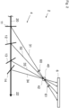
- Fig. 1 shows a schematic view of a first embodiment of a tomographic inspection apparatus 2.
- the inspection apparatus 2 comprises a beam source 5, a multi beam splitting and redirecting apparatus 4 and a beam detector 6.
- the beam source 5 is for example an X-ray source emitting a primary beam 20 along a common beam path 22.
- the multi beam splitting and redirecting apparatus 4 comprises multiple beam splitters 11, 12, 13, 14 arranged on the common beam path 22.
- the beam splitters 11, 12, 13, 14 are crystals, which each scatters the primary beam 20 via Bragg diffraction, thus generating a diffracted beamlet 31, 32, 33, 34 and attenuating the primary beam 20.
- Each beamlet 31, 32, 33, 34 travels in a beamlet direction 31a, 32a, 33a, 34a and is focused on an inspection point 40, where a sample 42 is placed.
- the beam detector 6 In the path of the beamlets 31, 32, 33, 34 behind the inspection point 40 the beam detector 6 is arranged, which detects an intensity distribution generated by the beamlets 31, 32, 33, 34.
- a three dimensional image data set of the sample 42 can be provided by measuring the intensity distribution. From the three dimensional image data set, a three dimensional tomographic image of the sample 42 can be calculated.
- the beam detector 6 may be an indirect detector or a direct conversion detector.
- the distance 18 between the beam splitters 11, 12, 13, 14 as well as the beamlet angle ⁇ 1 , ⁇ 2 , ⁇ 3 , ⁇ 4 , which the beamlets 31, 32, 33, 34 include with a direction of the primary beam 20, has to be properly adjusted.
- the Bragg angle which in this case corresponds with the beamlet angle ⁇ 1 , ⁇ 2 , ⁇ 3 , ⁇ 4 , depends on a wavelength of the primary beam 20 and the lattice spacing between the lattice planes, which scatters the primary beam 20.
- the lattice spacing has to be changed as well. This is done by choosing a material with a suitable lattice constant and orientating the crystal such that the primary beam 20 is scattered on a lattice plane with the desired Miller indices.
- a monochromatic X-ray primary beam with a wavelength of about 0,069 nm is directed at three beam splitters.
- the first beam splitter is fabricated of germanium and orientated so that the primary beam is scattered at the (022) lattice plane, generating a beamlet with a beamlet angle of about 10°.
- the second beam splitter is fabricated of silicon and orientated so that the primary beam is scattered at the (004) lattice plane, generating a beamlet with a beamlet angle of about 14°.
- the third beam splitter is fabricated of carbon and orientated so that the primary beam is scattered at the (333) lattice plane, generating a beamlet with a beamlet angle of about 30°.
- the beam splitters 11, 12, 13, 14 may be configured to each scattering a different portion of this energy spectrum. This makes it possible for a larger portion of the energy of the primary beam to be utilized for tomographic inspection.
- the beam splitters 11, 12, 13, 14 have to be manufactured from a suitable material and arranged in the correct orientation and distance 18 to each other, so that the beamlets 31, 32, 33, 34 generated from different portion of the energy spectrum still focus on the inspection point 40.
- An angle ⁇ between a first beam splitter 11 and a last beam splitter 14 of the multi beam splitting and redirecting apparatus 4 defines the angular range of the tomographic inspection apparatus 2 shown in Fig. 1 .
- the angle ⁇ should be chosen to be as large as possible.
- Fig. 2 shows a schematic view of a second embodiment of a tomographic inspection apparatus 2.
- the primary beam 20 is generated by a large beam source, for example a synchrotron source or an XFEL source, which is not shown in Fig. 2 .
- the beam splitters 11, 12, 13, 14 are configured to scatter the primary beam 20 in transmission geometry (Laue geometry) instead of reflection geometry (Bragg geometry).
- a focusing element 60 is arranged in front of the inspection point 40 and another focusing element 61 is arranged behind the inspection point 40.
- the focusing elements 60, 61 are for example X-ray focusing elements, that magnify and demag-nify X-rays, so as to change the spatial dimensions of the beamlet 31 when passing through the inspection point 40.
- Fig. 3 shows a schematic view of a third embodiment of a tomographic inspection apparatus 2.
- only two beam splitters 11, 12 are arranged on the common beam path 22.
- a separate beam detector 6 is provided for each beamlet 31, 32 generated by the beam splitters 11, 12, a separate beam detector 6 is provided.
- a crystal spectrometer 50 is placed on the common beam path 22 behind the beam splitters 11, 12.
- the crystal spectrometer 50 comprises a highly bent crystal, which offers a multitude of surfaces, on which the primary beam 20 is scattered, thus generating a diffracted spectrometer beam 52.
- a spectrometer beam detector 54 which is for example a two dimensional detector, analyzes the diffracted spectrometer beam 52 to measure the intensity in all parts of the energy spectrum of the primary beam 20.
- a direct beam camera 56 is placed behind the crystal spectrometer 50 in the common beam path 22 to detect the intensity of the remaining primary beam 20.
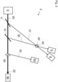
- Fig. 4 shows a schematic illustration of a fourth embodiment of a tomographic inspection apparatus 2.
- a direct beam splitter 70 is arranged in the path of the primary beam 20 in front of the beam splitters 11, 12, 13, 14 of a first beam splitter group 71.
- the direct beam splitter 70 splits of a part of the primary beam 20 into a secondary beam 74, which includes an angle with the primary beam 20. In the example shown in Fig. 4 , this angle is about 90°.
- the angle included between the primary beam 20 and the secondary beam 74 can be any angle between 0° and 180°.
- a second beam splitter group 72 with beam splitters 15, 16 is arranged in a secondary beam path 76 of the secondary beam 74 .
- the beam splitters 15, 16 are configured and arranged to generate beamlets 35, 36 by scattering the secondary beam 74 and focus the beamlets 35, 36 to the inspection point 40.
- the beam splitters 11, 12, 13, 14, 15, 16 can be placed on different sides of the sample 42.
- the beam splitters 11, 12, 13, 14 of the first beam splitter group 71 and the beam splitters 15, 16 of the second beam splitter group 72 may be part of a single multi beam splitting and redirecting apparatus 4 or each beam splitter group 71, 72 may constitute its own multi beam splitting and redirecting apparatus 4.
- the primary beam 20 and/or the secondary beam 74 may be split multiple times by multiple direct beam splitters 70 in order to create even more beam branches with their own beam splitter group 71, 72.
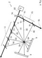
- Fig. 5 shows a schematic illustration of a fifth embodiment of a tomographic inspection apparatus 2, known as a single-splitter setup.
- the beam splitters 11, 12, 13 are realized as a single component, in this case a single crystal 80.
- the crystal 80 comprises grooves to define multiple scattering surfaces 81, 82, 83 and is bent, so that the scattering surfaces 81, 82, 83 include an inclination angle between them.
- the resulting beamlets 31, 32, 33 thus arrive from a slightly different position and at a slightly different angle at the inspection point 40.
- the crystal 80 in Fig. 5 comprises only three scattering surfaces 81, 82, 83, any number of scattering surfaces can be realized for a given crystal 80.
- the use of the single crystal 80 as beam splitters 11, 12, 13 allows for a miniaturization of the setup, as the size of the scattering surfaces can go down to the 10 ⁇ m range.
- the difference in the length of the beam paths of the beamlets 31, 32, 33 is so small, that the time delay between the beamlets 31, 32, 33 is in the femtosecond range. This allows a THz sample rate for 2D imaging.
- Fig. 6 shows a schematic illustration of an embodiment of a tomographic inspection apparatus 2 with multiple single crystals 80 acting as beam splitters.
- the single crystals 80 are all arranged on the common beam path 22 in that the beamlets 31, 32, 33 from every scattering surface 81, 82, 83 of every single crystal 80 is directed towards the inspection point 40.
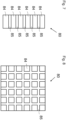
- a schematic illustration of a single crystal 80 comprising an optic material 84 and a non-optic material 85 is shown.
- the optical material 84 is configured to scatter the primary beam 20 in the direction of the inspection point 40 and act as the scattering surfaces 81, 82, 83 of the single crystal 80.
- the non-optic material 85 separates the areas with optic material 84 from each other.
- the single crystal 80 can be a grooved crystal or a patterned crystal.
- the pattern can be a pattern of crystalline and amorphous material, a pattern of crystalline materials with different lattice spacing or different chemical composition or chemical doping and/or a pattern obtained by lithographic techniques or by local ablation of material. The latter can be achieved by blocking part of the crystal surface from receiving the ablating radiation.
- Fig. 8 is a schematic illustration of a two dimensional, single component beam splitter comprising optic material 84 and non-optic material 85.
- the optic material 84 is patterned in a grid like fashion. In this way, the primary beam 20 is scattered two-dimensionally towards the inspection point 40.
Landscapes
- Physics & Mathematics (AREA)
- Spectroscopy & Molecular Physics (AREA)
- Engineering & Computer Science (AREA)
- General Engineering & Computer Science (AREA)
- High Energy & Nuclear Physics (AREA)
- Analysing Materials By The Use Of Radiation (AREA)
Abstract
Description
- The invention relates to a multi beam splitting and redirecting apparatus for a tomographic inspection apparatus. The invention further relates to a tomographic inspection apparatus and to a method for creating a three dimensional tomographic image of a sample.
- In many scientific and technological fields and applications, it is of strong interest to obtain volumetric information about a sample. Established methods for volumetric imaging techniques are computed tomography (CT) or computed laminography (CL), which employ X-ray beams to analyze the target. The sample is usually rotated around a given axis or the source and the detector are rotated around the sample. Angular projections of the sample are recorded and reconstructed using various algorithms resulting in volumetric data holding 3D sample information.
- This approach is facing a problem if one wants to improve volumetric acquisition time for obtaining dynamic volumetric information of very fast processes in the sample. In order to improve the acquisition time, the sample has to be rotated ever faster, at which point the centrifugal forces start to influence the sample. Also, if the source and the detectors are rotated, at some point the increasing rotation speed involved faces a physical limit. In an attempt to circumvent this physical limit, multi beam setups have been proposed. In such a structure, the sample or target is simultaneously hit by a plurality of beams, which are directed to the sample under different angles of incidence.
- In the publication "Hard x-ray multi-projection imaging for single-shot approaches", published 29th of November 2019 in ", a single crystal is placed in front of a sample to be analysed and an X-ray beam is directed at the crystal. The crystal acts as a beam splitter, scattering the X-ray beam on multiple lattice planes of the crystal, thereby generating multiple diffracted beamlets directed at the sample. In passing through the sample, the beamlets create simultaneous tomographic projections, which can be combined to a three dimensional tomographic image. However, this method requires the sample to be placed directly in front of the crystal, which imposes restrictions on the size of the samples to be analysed and the types of possible measurements.
- The publication "Multibeam x-ray optical system for high-speed tomography", published 12th of May 2020 in Volume 7, " discloses a multibeam X-ray optical system with a silicon crystal designed as a hyperbola shaped multiblade structure. When exposed to an X-ray beam, the silicon crystal scatters the X-ray beam via Bragg diffraction and focuses the beam on a sample. In this way, projection images can be obtained simultaneously from an angular range. However, the fabrication of the Si-crystal is complicated and the method requires an X-ray beam with large spatial dimensions.
- It is an object of the invention to provide a multi beam splitting and redirecting apparatus, a tomographic inspection apparatus and a method for creating a three dimensional tomographic image of a sample, which allow for flexible and very fast acquisition times while overcoming the technical restrictions in the prior art.
- The object is solved by a multi beam splitting and redirecting apparatus for a tomographic inspection apparatus, the multi beam splitting and redirecting apparatus comprising at least two beam splitters, which are arranged on a common beam path of a primary beam, wherein every beam splitter is configured to generate a beamlet by scattering the primary beam and to attenuate the primary beam and wherein the beam splitters are arranged to have a distance to each other, in that all beamlets are directed to an inspection point being distanced from the common beam path.
- The primary beam travels along the common beam path while being consecutively attenuated by the beam splitters. In each beam splitter, the primary beam is scattered, thus generating a beamlet for each beam splitter. After being generated by the beam splitters, the beamlets travel along a respective direct path to the inspection point. In the inspection point, a sample to be analyzed is placed. After passing through the sample, an intensity distribution of the beamlets is measured to acquire volumetric information about the sample. The measured intensity distribution is typically referred to as a projection in tomographic methods. The set of projection provides 3D image data suitable for creating a three dimensional tomographic image.
- As the beamlets are generated by beam splitters arranged to have a distance to each other on the common beam path, all the beamlets arrive at the inspection point from different directions, offering a high angular range for tomographic inspection. Only a single primary beam is required to achieve this angular range and there are no restrictions on the size of the sample.
- In comparison to the state of the art setups described above, the multi beam splitting and redirecting apparatus is extremely flexible, as the properties of the primary beam, the number of beamlets, the direction from which the beamlets arrive at the inspection points and the energy of the beamlets can all be easily adjusted.
- In the context of this specification, the term "tomographic" refers to an imaging technique in which different angular projections of a sample are recorded and subsequently reconstructed using commonly known reconstruction algorithms. The production of these tomographic images is based on the mathematical procedure of tomographic reconstruction, which results in 3D volumetric image data holding 3D sample information. In tomographic imaging techniques, which are frequently known, in particular in the field of medical imaging, the object is scanned full 360°. This is, however, not absolutely required for tomographic reconstruction of section images. In view of this, the term "tomographic" should not be understood as being limited to a full 360° inspection technique. In contrast to this, the tomographic inspection apparatus according to aspects of the invention is configured to perform a tomographic inspection applying in the inspection angle which is equal to or below 360°, in particular between 0° and 180°.
- Furthermore, in the context of this specification, the terms "beam" and "beamlet" refer to a directed beam of energetic radiation, including electromagnetic radiation and particle beams. The terms are in particular understood as not being limited to focused beams. Furthermore, the term "beamlet" is understood in that it refers to a scattered/reflected fraction of the primary beam, the intensity of which is lower when compared to the primary beam. The "beamlet" is directed to the inspection point. Although the beam and/or the beamlet are not necessarily focused, they can be focused. Hence, in particular, for adjusting the magnification, the beamlets can be focused before or after the inspection point.
- The distance between the beam splitters is in particular a predetermined distance. The distance is predetermined by the prerequisite that the beamlets should be directed on the inspection point. This does however not entail that the distance is fixed. The beam splitters are in particular movable, so that the distance between the beam splitters can be adjusted to a desired predetermined variable value. Even during an ongoing inspection, the distance might be slightly changed to improve the alignment of the beamlets. In particular, the distances between at least two consecutive beam-splitters are different from each other. For example, the distance between a first and a second beam splitter can be larger or smaller than the distance between the second and a third beam splitter.
- Preferably, the at least two beam splitters are crystals, which generate the beamlets by scattering the primary beam on lattice planes of the crystals, wherein in particular the beam splitters are amplitude splitters.
- In the context of this specification, an amplitude splitter is a beam splitter, which splits the amplitude of an incoming beam. In comparison, a wavefront splitter is a beam splitter, which splits a beam profile of the incoming beam.
- When an X-ray beam hits a solid object, the beam is scattered by the atoms of the object. In case the object is a crystal, a scattered beam is generated by positive interference on the lattice planes, if the X-ray beam hits the crystal at the right incident angle. A crystal used as one of the beam splitters scatters the primary beam on one of its lattice planes thus generating a beamlet and attenuating the primary beam.
- Advantageously, crystals can be employed as beam splitters for high energetic beams like X-rays or gamma rays, as other beam splitters typically used for electromagnetic beams in the optical spectrum cannot be utilized for these beams.
- The angle at which X-ray beams are scattered at crystals depends on the wavelength of the beam, the lattice spacing between the lattice planes at which the beam is scattered and the order of diffraction given by the Miller indices. For this reason, the crystals have to be arranged at the right orientation, so that the primary beam enters the crystal at the right angle to be scattered by lattice planes with the desired Miller indices for a specified wavelength of a given primary beam.
- For example, a first beam splitter can be arranged so as to scatter the primary beam at the (111) lattice plane, a second beam splitter can be arranged so as to scatter the primary beam at the (004) lattice plane and a third beam splitter can be arranged so as to scatter the primary beam at the (333) lattice plane.
- In particular, at least one of the beam splitters is a mono-element crystal, which means a crystal comprising only a single chemical element. The crystal material is for example carbon in the form of diamond, silicon, germanium or tungsten. However, the crystal material can be any element spanning the entire periodic element table from lithium to uranium. The beam splitter can be a single crystal or a polycrystalline material, for example a mosaic crystal or a single crystal with imperfections. The beam splitter material can also be composed of more than one chemical element, for example, the crystal can be manufactured from CSi, SiGe, GaAs, CdTe. However, any combination of the chemical elements of the periodic table forming a crystalline structure can be suitable. The beam splitters can also be manufactured from crystals of complex molecules forming organic crystals.
- The amplitude splitters used as beam splitters may be replaced by wavefront splitters, for example crystals, gratings, multilayers or mirrors. In this case, each beamlet could have a larger spectrum while having a smaller spatial size. At this purpose, the use of asymmetric diffraction planes with positive magnification is particularly useful because of the enlargement of the acceptance bandwidth together with the enlargement of the beamlet to compensate for the smaller spatial size due to the wavefront division. This geometry is particularly useful in the case of a highly monochromatic primary beam, where amplitude splitters could not be used because a first beam splitter would diffract most of the primary beam. In the case of a highly monochromatic primary beam, multiple splittings could still be achieved with a series of wavefront splitters while maintaining large enough beamlets because of the magnification due to the asymmetry.
- With the multi beam splitting and redirecting apparatus according to aspects of the invention, for example synchrotrons will be able to achieve 3D information with a sampling rate in the kHz range. X-ray free-electron lasers (XFELs), that can produce trains of pulses with a sampling rate in the MHz range, will be able to achieve 3D information with a MHz sampling rate, using just a single pulse with repetition rate in the MHz region. For XFELs that can produce trains of pulses from Hz up to MHz rates, the invention provides access to 2D and 3D images with a sampling rate in picosecond to nanosecond range using exposure from a single X-ray pulse. As the technology of the multi beam splitting and redirecting apparatus can create a fan of angularly separated beams passing through the sample, each projection can be set to different photon energy, selecting a narrow band from the input spectrum. This will enhance tomography techniques by acquiring energy-resolved volumes. As the multi beam splitting and redirecting apparatus splits the primary beam in one plane, multiple planes are as well achievable if two or more primary beams are present. Then, the number of input beams will set the number of multi-projection planes. High spatial resolution of under 1µm can be achieved by employing focusing optics, e.g. focusing elements, especially with nanometer scale focal spots in front of the sample, to exploit the magnification geometry or by installing magnifying/focusing optics just after the sample, as it is done in visible light microscopy, e.g. in a defocused microscopy geometry.
- In addition, with the inventive multi beam splitting and redirecting apparatus it is possible to overcome the rotation-limited barrier for 3D imaging with X-rays and achieve an acquisition rate up to the MHz range for 3D images. Entire 3D videos may be captured with frames spaced in time by milliseconds to nanoseconds. The acquisition rate of 3D images is not limited anymore by the fundamental physical limit of the rotation speed of the object or of the setup causing centrifugal forces.
- The inventive multi beam splitting and redirecting apparatus also breaks the picosecond and femtosecond barrier for imaging with X-rays. With the inventive multi beam splitting and redirecting apparatus, the acquisition rate of 2D images is not limited anymore by the limited acquisition rate of detectors. Indeed, there is no detector working below the nanosecond frame rate because of a fundamental physical limit: electrons have a limited charge carrier mobility in semiconductors preventing sample rates below one nanosecond for 2D detectors. Therefore, there is no detector that can work at picosecond frame rates. With the setup described in this specification it is possible to bypass this fundamental limit.
- Further, the inventive multi beam splitting and redirecting apparatus breaks the picosecond barrier for 3D imaging, realizing entire 3D videos with frames spaced in time in the picosecond range, i.e. a 3D GHz video. With the inventive multi beam splitting and redirecting apparatus, it is possible to record an entire 3D image in a picosecond timescale. The acquisition rate of 3D images is not limited anymore by the fundamental physical limit of the rotation speed or by the limited frame rate of the detectors.
- The beamlets generated by the beam splitters pass through the object producing each a projection image of the sample each at a different viewing angle. Each projection may be recorded by a different detector, or they may be recorded by a single detector large enough to accommodate all the projections, or by a combination of detectors. Each beamlet has gone through a different optical path before reaching the sample, so it has traversed a different length, therefore the projections have a time difference equal to the difference in length divided by the speed of light. Depending on the distance between the beam splitters, this time difference can be set in the picosecond range to nanosecond scale range for practical applications. All the projections are recorded without moving neither the sample nor the beam splitters or a beam source or the detectors. Instead of rotating the sample or detector rather the beams are "rotated" around the sample. The difference in time between the projections is in the picosecond range to nanosecond range.
- The multi beam splitting and redirecting apparatus can be used in three modalities:
- For 3D MHz imaging a difference in time in the picosecond range between the projections is irrelevant, as the difference in time between all the projections has to be in the sub-microsecond or nanosecond time range. A picosecond difference in time between the projections is even more irrelevant for kHz 3D imaging where the difference in time between all the projections has to be in the sub-millisecond or microsecond time range. Therefore, all the projections can be considered as taken at the same time for samples with adequate velocities for the purpose of 3D MHz scale sampled or kHz scale sampled imaging. From these projections, it is possible to reconstruct a 3D MHz or kHz image, each image as a tomographic frame with mentioned sampling. Naturally, to have a 3D MHz or kHz video, the cameras or detectors that record the projections have to work at MHz or kHz frame rate.
- For 2D GHz imaging the time difference between the projections is in the picosecond range. By choosing different materials and lattice orientations for the beam splitters, it is possible to record 2D images of dynamic phenomena in the picosecond time range, i.e. a GHz 2D video. Using the multi beam splitting and redirecting apparatus, a 2D GHz video can be recorded even with "slow" detectors by using a single bunch of X-ray with a time width of picoseconds or lower. Indeed, the image recorded by each detector has a time difference between the others in the picosecond range, so they can be mounted in a GHz 2D video.
- The multi beam splitting and redirecting apparatus described above can also be combined with other methods and geometries of beam splitting to achieve 3D GHz imaging. Indeed, the primary beam can be split in two or more beams with large enough intensity to be used each of them as an input beam for the described multi beam splitting and redirecting apparatus. Therefore, each branch of the primary beam can be used as an input beam for a multi beam splitting and redirecting apparatus, with all the multi beam splitting and redirecting apparatuses imaging the same sample. Placing the multi beam splitting and redirecting apparatuses and the beam splitters at the right distances, all the multi beam splitting and redirecting apparatuses will have their beamlets hitting the sample exactly at the same time but from different directions. Therefore, they will produce a projection of the sample at different angles but exactly at the same time, from which it is possible to reconstruct a 3D image of the sample. Then, in each multi beam splitting and redirecting apparatus, the beamlets will have a time-difference in the picosecond range. Therefore, these multiple multi beam splitting and redirecting apparatuses will generate sets of projections of the object where each set has a time difference in the picosecond range in relation to the other, and each set is composed of projections recorded exactly at the same time but from different angles. From each set can be reconstructed an instantaneous 3D image of the object, while these 3D images have a time difference in relation to the other in the picosecond range, so realizing a 3D video with each frame spaced by picosecond, i.e. a 3D GHz video.
- Apart from crystalline beam splitters, the beam splitters can be micro-and nano-manufactured beam splitters of refraction or reflection type. Micro- and nano-manufactured beam splitters use coherent diffraction in periodic structures that are manufactured for this purpose. Examples include gratings, periodic 2D structures manufactured on top of a transparent support layer and zone-plates. Refraction and reflection splitters use refraction or reflection instead of coherent diffraction for splitting the beam, as it happens with visible light. This type of beam splitter is mostly used at relatively low X-ray energies, including UV radiation. These beam splitters include multilayer structures or micro- and nano-manufactured structures, for example capillary lenses or Laue lenses. Multilayer mirrors or grazing-incident mirrors can also be used and considered as beam splitters. Typically, this type of beam splitter works as a wave front beam splitter, however, if manufactured thin-enough, mirrors can also be used as amplitude beam splitters too.
- Preferably, at least one of the at least two beam splitters is configured to scatter the primary beam in reflection geometry and/or at least one of the at least two beam splitters is configured to scatter the primary beam in transmission geometry.
- In reflection geometry, also known as Bragg diffraction, the lattice planes that diffract the primary beam are parallel to a main surface of the crystal. In transmission geometry, also known as Laue diffraction, the lattice planes that diffract the primary beam are perpendicular to the main surface of the crystal. In the context of the present invention, the main surface of the crystal is defined as the surface which the primary beam hits first.
- According to an embodiment of the invention, each beam splitter is configured and/or orientated to scatter a different portion of an energy spectrum of the primary beam, in particular by choosing a specified crystal material and/or by orientating the crystals so as to diffract the primary beam on specified lattice planes.
- By configuring and/or orientating every beam splitter so as to scatter a different portion of the energy spectrum of the primary beam, the energy of the primary beam is used efficiently by the multi beam splitting and redirecting apparatus. Additionally, it ensures that every beamlet generated by the beam splitters still has a sufficient, and in particular substantially equivalent, energy, even though the primary beam is consecutively attenuated by passing through the beam splitters.
- Different crystal materials offer different lattice spacings. By changing the material of a beam splitter and thus changing the lattice spacing, beams with different energy will be scattered at a given angle. This makes it possible to tune an energy of a beamlet to be scattered in the direction of the inspection point. The same effect can be achieved by orientating a given crystal so as to diffract the primary beam on another lattice plane with a different lattice spacing.
- In particular, the primary beam is a white beam and/or a pink beam and/or a monochromatic beam, wherein a bandwidth dE/E of a white beam is substantially 10-0, a bandwidth dE/E of a pink beam is substantially 10-2 and a bandwidth dE/E of a monochromatic beam is substantially 10-4. E is an average photon energy and dE is half of the bandwidth of the photon energies.
- White beams and pink beams are advantageous because of their broad energy spectrum. Due to the broad energy spectrum, it is possible for each beam splitter to scatter a different portion of the energy spectrum of the primary beam even with a large number of beam splitters involved. Monochromatic beams offer a narrow bandwidth, making it possible to examine the sample with a single energy, i.e. that of the primary beam.
- Preferably the primary beam is a, in particular pulsed, X-ray beam or gamma ray beam or neutron beam or extreme UV beam, wherein a wavelength of the extreme UV beam is less than 120 nm. In particular, a wavelength of the primary beam is 0.01 to 1 nm. This wavelength has proven to be well suited for the primary beam. However, primary beams with bigger or smaller wavelengths might also be employed.
- X-rays are a widely used tool for acquisition of volumetric data. There exists a number of high brilliance X-ray sources ranging from laboratory sources to synchrotron sources and X-ray free-electron laser (XFEL) sources, which provide X-ray beams well suited as primary beams for the multi beam splitting and redirecting apparatus. As gamma rays differ from X-rays mainly by their origin and not necessarily by their energy spectrum, the multi beam splitting and redirecting apparatus is suitable for gammy ray primary beams as well. In addition, the multi beam splitting and redirecting apparatus can also be used with a neutron beam since neutron diffraction is very similar to X-ray diffraction.
- Beam splitters for neutrons use the same mechanics of coherent diffraction as X-ray beam splitters, since neutrons can be treated as waves as well. In embodiments applying beam splitters for neutrons, preferable materials are those not having a high cross-section for neutron absorption, for example boron. Of course, for these embodiments, the scattering angles of the beam splitters have to be recalculated as well as the intensities of the beamlets.
- Beam splitters for UV exist in all the types previously mentioned, including crystalline beam-splitters, gratings, micro- and nano-structured beam splitters and refraction or reflection beam-splitters.
- Preferably the at least two beam splitters are configured to generate the beamlets along beamlet directions, wherein the beamlet direction of each beamlet includes a different beamlet angle with a direction of the primary beam.
- For example, in case the beam splitters are crystals scattering the primary beam via Bragg diffraction, the scattering in each beam splitter will involve a different Bragg angle.
- By generating beamlets including different beamlet angles with the direction of the primary beam, every beamlet will arrive in the inspection point from a different direction thus offering a high angular range for tomographic inspection.
- The at least two beam splitters comprise preferably a first beam splitter and a second beam splitter, wherein a first beamlet generated by the first beam splitter includes an angle with a second beamlet generated by the second beam splitter, wherein the angle is between 0,1 ° and 179,9°, in particular, the angle is between 0,1° and 90°, further in particular the angle is between 0,1° and 60°.
- Higher angles included by the beamlets offer higher angular ranges for tomographic inspection. The angle between the beamlets of consecutive beam splitters is in particular always higher than 0° and lower than 180°.
- In particular, an angle between the beamlets of two consecutive beam splitters is at least 1°.
- Preferably, at least one of the beam splitters comprises a bent crystal and/or a mosaic crystal and/or is a crystal consisting of or comprising elements with an atomic number of at least six, in particular at least thirty-two, in particular at least forty-nine.
- Six is the atomic number of carbon, thirty-two is the atomic number of germanium and forty-nine is the atomic number of indium. By using bent crystals, mosaic crystals and/or crystals made from elements with a high atomic number a crystal bandwidth, i.e. the bandwidth of the scattered beamlet, is broadened. With a large crystal bandwidth, the crystal diffracts a larger portion of the energy spectrum of the primary beam. In addition to this, a divergence of the primary beam after passing through the crystal is increased. The crystal bandwidth of a crystal is the full width at half maximum (FWHM) of the beamlets scattered by the crystal.
- In particular the crystal is bent, in particular solely, by internal crystal bending. For example, solely internal crystal bending can be achieved with selective ion implantation and/or a defined composition gradient. Mosaic crystals are crystals composed of a multitude of crystallites slightly misaligned with respect to each other, or crystals with internal defects or strain.
- A broadening of the crystal bandwidth can also be achieved by using elements with a high atomic number, for example germanium or indium. If a crystal made from multiple elements, e.g. antimonide, is chosen as a beam splitter, an average atomic number of the crystal is in particular at least thirty-two, in particular at least forty-nine.
- In particular, a flux of the beamlets is increased by increasing the spectral acceptance of the crystal and/or by using asymmetric diffraction with a grazing incidence geometry, which results in a positive magnification.
- Preferably, the at least two beam splitters are part of one single component, in particular a single crystal, wherein this single component comprises multiple scattering surfaces, that include an inclination angle between each other. In particular, the single component is bent as well as grooved or patterned to form the multiple scattering surfaces. This setup is also called a single-splitter setup. Advantageously, this setup is very space-saving, as the size of the scattering surfaces can go down to the 10 µm range. Since the small space between the diffracting elements causes the time delay between the beamlets to be in the femtosecond range, this setup allows very fast 2D imaging with a THz sample rate. In particular, multiple single crystals are arranged along the common beam path.
- The single crystal can be a grooved crystal, wherein the grooves can be manufactured by mechanical means, etching, laser evaporation and/or other manufacturing techniques.
- The single crystal can be a patterned crystal comprising a pattern of crystalline material and amorphous material, wherein the amorphization of parts of the crystal can be achieved by chemical, thermic and/or mechanical means, laser, ion implantation and/or by lithography.
- The single crystal can be a patterned crystal comprising a pattern of crystalline materials with different lattice spacing and/or different chemical composition and/or chemical doping. In particular, the crystalline materials are manufactured by vapor deposition with or without a chemical reaction on the original material and/or other deposition techniques, in particular sputter deposition or laser deposition. Alternatively, the crystalline materials are manufactured with other techniques that include the generation of stress in the material to change the lattice spacing in some layers as well as the locations of the material in the single crystal.
- The single crystal can be a patterned crystal, wherein the pattern is introduced into the patterned crystal using standard lithography technologies or by radiation induced or assisted erosion/ablation of material. The pattern can be generated by blocking a part or parts of the crystal surface from receiving radiation.
- In particular, the multi beam splitting and redirecting apparatus comprises a recombiner crystal, which is configured and arranged to focus the beamlets generated by the single crystal into the inspection point. This allows the inspection of big samples.
- Preferably the multi beam splitting and redirecting apparatus comprises at least one direct beam splitter and at least two beam splitter groups, which comprise the at least two beam splitters, wherein the at least one direct beam splitter is arranged on the common beam path and configured to generate a secondary beam by scattering the primary beam and to attenuate the primary beam, wherein the attenuated primary beam is emitted along the common beam path and the secondary beam is emitted along a secondary beam path, wherein one of the at least two beam splitter groups is arranged on the common beam path behind the direct beam splitter and another of the at least two beam splitter groups is arranged on the secondary beam path.
- In other words, the primary beam is split into multiple branches and directed to multiple beam splitter groups. Advantageously, the angular range for tomographic inspection is increased even further as beamlets from different beam splitter groups are directed at the inspection point from different sides. In order to further increase the angular range, the primary beam can be split multiple times. The primary beam is split by the direct beam splitter. The direct beam splitter is in particular a crystal used as an amplitude splitter or wavefront splitter or a mirror used as a wavefront splitter. In particular, the direct beam splitter splits the primary beam so that the beamlets generated by the first beam splitter group lie in a different, in particular non-parallel, plane than the beamlets generated by the second beam splitter group. This allows for volumetric inspection from different viewpoints.
- Preferably the multi beam splitting and redirecting apparatus is configured in that a time period, in which all the beamlets created from a single pulse of a pulsed primary beam reach the inspection point, is less than a microsecond, in particular less than a nanosecond, in particular in the range between one picosecond to one nanosecond.
- By keeping the time difference between the beamlets generated from a single pulse in the nanosecond or even picosecond range, it is possible to create three dimensional tomographic images of very fast dynamic processes.
- In particular, the multi beam splitting and redirecting apparatus comprises at least two beam splitters of different material, wherein a difference of a lattice spacing of the different materials is less than 65%, in particular less than 20%, in particular less than 5%.
- By providing two or more beam splitters with very similar lattice parameters, two or more beamlets with very small time separation in the picosecond or femtosecond range are generated, which can be utilized for interferometry. An even faster interferometry could be realized by miniaturization of this system. Indeed the time separation between the beamlets is proportional to the size of the system. A miniaturized system of this kind could be realized by grooving and bending a crystal that has a gradient of concentration of two different elements, e.g. SixGe1-x, so that the surfaces of the crystal left between the grooves have a gradient of lattice parameter and each surface acts as a slightly different material but with similar lattice parameter, so that they will diffract beamlets with the same energy but with a separation in time proportional to the distance between them. This type of system can be so miniaturized that the size of the crystalline surfaces can go down to the 10-µm range, as the space between them, therefore the time distance between the beamlets can be in the femtosecond range. Since these beamlets have the same energy, they interfere allowing for femtosecond range interferometry.
- In particular a smoothing crystal and/or a normalization mask is arranged in the path of the primary beam in front of the multi beam splitting and redirecting apparatus, wherein the smoothing crystal is configured and arranged to diffract the primary beam in transmission geometry. Advantageously, the smoothing crystal will smooth away non-uniformities of the beam due to the phenomenon called the Bormann Triangle. According to an embodiment, the smoothing crystal is made of diamond or a lighter material. According to a different embodiment, the smoothing crystal is made from a material heavier than diamond. The normalization mask is configured to remove the spatial structure of the primary beam. Alternatively, the spatial structure of the primary is removed by an algorithm.
- The object is further solved by a tomographic inspection apparatus, comprising a beam source, at least one beam detector and a multi beam splitting and redirecting apparatus according to any of the previously mentioned embodiments, wherein the beam source is configured to emit a primary beam, wherein the at least one beam detector is arranged and configured to measure an intensity of the beamlets after passing through the inspection point, wherein the tomographic inspection apparatus is configured to create a three dimensional image data set of a sample in the inspection point under consideration of the intensity of the beamlets measured with the at least one beam detector and under consideration of beamlet angles, which the respective beamlets include with a direction of the primary beam.
- The tomographic inspection apparatus embodies same or similar features, advantages and properties as the multi beam splitting and redirecting apparatus, which should therefore not be repeated.
- In addition to this, the tomographic inspection apparatus employs tomographic methods known in the art to generate three dimensional tomographic images from the three dimensional image data set.
- The beam source may be an X-ray source, a gamma ray source and/or a neutron source. In particular, the beam source is a laboratory source and/or a synchrotron source and/or a XFEL source and/or any other type of appropriate beam source.
- The beam detector is in particular an indirect X-ray, gamma, neutron and/or UV detector, in particular comprising a scintillator and a visible light detector, for example, a charge coupled device (CCD) or complementary metal-oxide-semiconductor (CMOS) or scientific complementary metal-oxide-semiconductor (sCMOS). According to another embodiment, the beam detector is a direct conversion single-photon counting or integrating detector. In particular, the detector comprises at least one camera and/or a large area detector.
- According to an embodiment, a single beam detector is arranged to detect all the beamlets passing through the inspection point. The single detector is in particular a curved detector. According to a different embodiment, the beamlets are detected by multiple beam detectors. In particular, every beamlet is detected by a different beam detector. In particular, at least one of the detectors is a camera, wherein the position of the at least one camera and the number of cameras is chosen based on the desired vision angle and acquisition time.
- Preferably, the inspection apparatus comprises a crystal spectrometer arranged on the common beam path behind the multi beam splitting and redirecting apparatus, wherein the crystal spectrometer comprises a bent crystal configured to diffract substantially the entire energy spectrum of the primary beam and generate a diffracted spectrometer beam, wherein a spectrometer beam detector configured to record the diffracted spectrometer beam is arranged in a beam path of the diffracted spectrometer beam, wherein the spectrometer beam detector is in particular a two dimensional detector.
- The crystal spectrometer comprises a highly bent crystal which offers a multitude of Bragg angles to the primary beam. With the crystal spectrometer and the spectrometer beam detector it is possible to analyze which bands of energy are used in the beamlets so as to help to align the beam splitters.
- Preferably, the inspection apparatus comprises at least one focusing element, which is arranged in a path of at least one of the beamlets in front of and/or behind the inspection point.
- In particular, the focusing element is an X-ray focusing element and/or a gamma ray focusing element and/or a neutron focusing element. The X-ray focusing element is in particular a focusing or defocusing X-ray lens. Advantageously, the focusing element magnifies or demagnifies a beamlet. For example, an X-ray focusing element is useful when a direct conversion detector is used as a beam detector, as in this case lenses for visible light cannot be used for magnification.
- In particular, the tomographic inspection apparatus comprises at least two beam sources each generating a primary beam, wherein the primary beams generated by the at least two beam sources each are directed at a different multi beam splitting and redirecting apparatus. Advantageously, this allows a high angular range >180° and makes it possible to provide projections lying on different planes.
- The object is further solved by a method for creating a three dimensional tomographic image of a sample, wherein the sample is placed in an inspection point, wherein a primary beam is guided along a common beam path, wherein at least two beam splitters are arranged in a distance to each other on the common beam path, each generating a beamlet and attenuating the primary beam by scattering the primary beam, wherein all the beamlets are directed to the inspection point, which is distanced from the common beam path, wherein an intensity of the beamlets after passing through the inspection point is measured with at least one beam detector, wherein a three dimensional image data set of the sample in the inspection point is created under consideration of the intensity of the beamlets measured with the at least one beam detector and under consideration of beamlet angles, which the respective beamlets include with a direction of the primary beam.
- Also, the method embodies same or similar features, advantages and properties as the tomographic inspection apparatus and the inventive multi beam splitting and redirecting apparatus.
- In order to cover a full 360° of the sample, the sample can be rotated after acquisition of a first image and before acquisition of a subsequent second image.
- According to an embodiment of the method, the two beam splitters are crystals, which generate the beamlets by scattering the primary beam on lattice planes of the crystals, wherein in particular the beam splitters are amplitude splitters.
- Preferably at least one of the at least two beam splitters scatters the primary beam in reflection geometry and/or at least one of the at least two beam splitters scatters the primary beam in transmission geometry.
- Each beam splitter preferably scatters a different portion of an energy spectrum of the primary beam, in particular by choosing a specified crystal material and/or by orientating the crystals, so as to diffract the primary beam on specified lattice planes.
- Preferably the primary beam is a, in particular pulsed, X-ray beam or gamma ray beam or neutron beam.
- The at least two beam splitters preferably generate the beamlets along beamlet directions, wherein the beamlet direction of each beamlet includes a different beamlet angle with a direction of the primary beam.
- Preferably the at least two beam splitters comprise a first beam splitter and a second beam splitter, wherein a first beamlet generated by the first beam splitter includes an angle with a second beamlet generated by the second beam splitter wherein the angle is between 0,1 ° and 179,9°, in particular, the angle is between 0,1° and 90°, further in particular the angle is between 0,1° and 60°.
- At least one of the beam splitters preferably comprises a bent crystal and/or a mosaic crystal and/or is a crystal consisting of or comprising elements with an atomic number of at least thirty-two, in particular at least forty-nine.
- According to an embodiment, the at least two beam splitters are part of a single crystal, wherein the single crystal is grooved and bent as to comprise multiple scattering surfaces, that include an inclination angle between them.
- Preferably at least one direct beam splitter is arranged on the common beam path, generates a secondary beam by scattering the primary beam and attenuates the primary beam, wherein the attenuated primary beam is emitted along the common beam path and the secondary beam is emitted along a secondary beam path, wherein one of at least two beam splitter groups, comprising the at least two beam splitters, is arranged on the common beam path behind the direct beam splitter and another of the at least two beam splitter groups is arranged on the secondary beam path.
- Preferably a time period, in which all the beamlets created from a single pulse of a pulsed primary beam reach the inspection point, is less than a microsecond, in particular less than a nanosecond.
- According to an embodiment a crystal spectrometer is arranged on the common beam path behind the multi beam splitting and redirecting apparatus, wherein the crystal spectrometer comprises a bent crystal configured to diffract substantially the entire energy spectrum of the primary beam and generate a diffracted spectrometer beam, wherein a spectrometer beam detector is arranged in a beam path of the diffracted spectrometer beam and records the diffracted spectrometer beam, wherein the spectrometer beam detector is in particular a two dimensional detector.
- Preferably at least one focusing element is arranged in a path of at least one of the beamlets in front of and/or behind the inspection point.
- In particular, the sample is rotated and each beamlet has a different energy. In this way, an energy-resolved tomography can be realized. Therefore, it is possible to attain multiple 3D images with different energies for each rotation of the sample. The method can also be combined with a previous splitting of the beam or with multiple sources to produce multiple multi beam splitting and redirecting apparatuses looking at the same object, so having beamlets with the same energy passing through the sample from different directions, therefore obtaining multiple 3D images with different energies without any rotation of the sample.
- Further characteristics of the invention will become apparent from the description of the embodiments according to the invention together with the claims and the included drawings. Embodiments according to the invention can fulfill individual characteristics or a combination of several characteristics.
- The invention is described below, without restricting the general teaching of the invention, based on exemplary embodiments, wherein reference is made expressly to the drawings with regard to the disclosure of all details according to the invention that are not explained in greater detail in the text. The drawings show in:
- Fig. 1
- a schematic view of an embodiment of a tomographic inspection apparatus with a multi beam splitting and redirecting apparatus in reflection geometry,
- Fig. 2
- a schematic view of an embodiment of a tomographic inspection apparatus with a multi beam splitting and redirecting apparatus in transmission geometry,
- Fig. 3
- a schematic view of an embodiment of a tomographic inspection apparatus with a crystal spectrometer,
- Fig. 4
- a schematic illustration of an embodiment of a tomographic inspection apparatus with a direct beam splitter and multiple beam splitter groups,
- Fig. 5
- a schematic illustration of an embodiment of a tomographic inspection apparatus with a single crystal with multiple scattering surfaces,
- Fig. 6
- a schematic illustration of an embodiment of a tomographic inspection apparatus with multiple single crystals acting as beam splitters,
- Fig. 7
- a schematic illustration of a single component beam splitter comprising an optic material and a non-optic material,
- Fig. 8
- a schematic illustration of a two dimensional, single component beam splitter comprising an optic material and a nonoptic material.
- In the drawings, same or similar elements or respectively corresponding parts are provided with the same reference numbers in order to prevent the item from needing to be reintroduced.
-
Fig. 1 shows a schematic view of a first embodiment of atomographic inspection apparatus 2. Theinspection apparatus 2 comprises abeam source 5, a multi beam splitting and redirectingapparatus 4 and abeam detector 6. Thebeam source 5 is for example an X-ray source emitting aprimary beam 20 along acommon beam path 22. The multi beam splitting and redirectingapparatus 4 comprisesmultiple beam splitters common beam path 22. Thebeam splitters primary beam 20 via Bragg diffraction, thus generating a diffractedbeamlet primary beam 20. Eachbeamlet beamlet direction inspection point 40, where asample 42 is placed. In the path of thebeamlets inspection point 40 thebeam detector 6 is arranged, which detects an intensity distribution generated by thebeamlets beamlets sample 42 from different directions, a three dimensional image data set of thesample 42 can be provided by measuring the intensity distribution. From the three dimensional image data set, a three dimensional tomographic image of thesample 42 can be calculated. Thebeam detector 6 may be an indirect detector or a direct conversion detector. - In order to focus the
beamlets inspection point 40, thedistance 18 between thebeam splitters beamlets primary beam 20, has to be properly adjusted. According to Bragg's law, the Bragg angle, which in this case corresponds with the beamlet angle Θ1, Θ2, Θ3, Θ4, depends on a wavelength of theprimary beam 20 and the lattice spacing between the lattice planes, which scatters theprimary beam 20. Therefore, in order to change the beamlet angle Θ1, Θ2, Θ3, Θ4 of aprimary beam 20 with a given wavelength, the lattice spacing has to be changed as well. This is done by choosing a material with a suitable lattice constant and orientating the crystal such that theprimary beam 20 is scattered on a lattice plane with the desired Miller indices. - For example, a monochromatic X-ray primary beam with a wavelength of about 0,069 nm is directed at three beam splitters. The first beam splitter is fabricated of germanium and orientated so that the primary beam is scattered at the (022) lattice plane, generating a beamlet with a beamlet angle of about 10°. The second beam splitter is fabricated of silicon and orientated so that the primary beam is scattered at the (004) lattice plane, generating a beamlet with a beamlet angle of about 14°. The third beam splitter is fabricated of carbon and orientated so that the primary beam is scattered at the (333) lattice plane, generating a beamlet with a beamlet angle of about 30°.
- When a
primary beam 20 with a broad energy spectrum is used, for example a pink beam or a white beam, thebeam splitters beam splitters distance 18 to each other, so that thebeamlets inspection point 40. - An angle δ between a
first beam splitter 11 and alast beam splitter 14 of the multi beam splitting and redirectingapparatus 4 defines the angular range of thetomographic inspection apparatus 2 shown inFig. 1 . To achieve a high angular range for tomographic inspection, the angle δ should be chosen to be as large as possible. -
Fig. 2 shows a schematic view of a second embodiment of atomographic inspection apparatus 2. In this embodiment, theprimary beam 20 is generated by a large beam source, for example a synchrotron source or an XFEL source, which is not shown inFig. 2 . In addition, thebeam splitters primary beam 20 in transmission geometry (Laue geometry) instead of reflection geometry (Bragg geometry). - In a beam path of the
beamlet 31, a focusingelement 60 is arranged in front of theinspection point 40 and another focusingelement 61 is arranged behind theinspection point 40. The focusingelements beamlet 31 when passing through theinspection point 40. -
Fig. 3 shows a schematic view of a third embodiment of atomographic inspection apparatus 2. In this embodiment, only twobeam splitters common beam path 22. For eachbeamlet beam splitters separate beam detector 6 is provided. In addition, acrystal spectrometer 50 is placed on thecommon beam path 22 behind thebeam splitters crystal spectrometer 50 comprises a highly bent crystal, which offers a multitude of surfaces, on which theprimary beam 20 is scattered, thus generating a diffractedspectrometer beam 52. Aspectrometer beam detector 54, which is for example a two dimensional detector, analyzes the diffractedspectrometer beam 52 to measure the intensity in all parts of the energy spectrum of theprimary beam 20. Thus, it is possible to analyze which parts of the energy spectrum are splitted of into thebeamlets beam splitters primary beam 20, thebeam splitters direct beam camera 56 is placed behind thecrystal spectrometer 50 in thecommon beam path 22 to detect the intensity of the remainingprimary beam 20. -
Fig. 4 shows a schematic illustration of a fourth embodiment of atomographic inspection apparatus 2. In this embodiment, adirect beam splitter 70 is arranged in the path of theprimary beam 20 in front of thebeam splitters beam splitter group 71. Thedirect beam splitter 70 splits of a part of theprimary beam 20 into asecondary beam 74, which includes an angle with theprimary beam 20. In the example shown inFig. 4 , this angle is about 90°. However, the angle included between theprimary beam 20 and thesecondary beam 74 can be any angle between 0° and 180°. In asecondary beam path 76 of the secondary beam 74 a secondbeam splitter group 72 withbeam splitters beam splitters beam splitters beamlets secondary beam 74 and focus thebeamlets inspection point 40. - With the
tomographic inspection apparatus 2 according to this embodiment a higher angular range for tomographic inspection can be achieved, as thebeam splitters sample 42. Thebeam splitters beam splitter group 71 and thebeam splitters beam splitter group 72 may be part of a single multi beam splitting and redirectingapparatus 4 or eachbeam splitter group apparatus 4. - To increase the angular range even further, the
primary beam 20 and/or thesecondary beam 74 may be split multiple times by multipledirect beam splitters 70 in order to create even more beam branches with their ownbeam splitter group -
Fig. 5 shows a schematic illustration of a fifth embodiment of atomographic inspection apparatus 2, known as a single-splitter setup. In this embodiment, thebeam splitters single crystal 80. Thecrystal 80 comprises grooves to define multiple scattering surfaces 81, 82, 83 and is bent, so that the scattering surfaces 81, 82, 83 include an inclination angle between them. The resulting beamlets 31, 32, 33 thus arrive from a slightly different position and at a slightly different angle at theinspection point 40. Even though thecrystal 80 inFig. 5 comprises only three scatteringsurfaces crystal 80. - The use of the
single crystal 80 asbeam splitters beamlets beamlets -
Fig. 6 shows a schematic illustration of an embodiment of atomographic inspection apparatus 2 with multiplesingle crystals 80 acting as beam splitters. Thesingle crystals 80 are all arranged on thecommon beam path 22 in that thebeamlets scattering surface single crystal 80 is directed towards theinspection point 40. - In
Fig. 7 a schematic illustration of asingle crystal 80 comprising anoptic material 84 and anon-optic material 85 is shown. Theoptical material 84 is configured to scatter theprimary beam 20 in the direction of theinspection point 40 and act as the scattering surfaces 81, 82, 83 of thesingle crystal 80. Thenon-optic material 85 separates the areas withoptic material 84 from each other. Thesingle crystal 80 can be a grooved crystal or a patterned crystal. The pattern can be a pattern of crystalline and amorphous material, a pattern of crystalline materials with different lattice spacing or different chemical composition or chemical doping and/or a pattern obtained by lithographic techniques or by local ablation of material. The latter can be achieved by blocking part of the crystal surface from receiving the ablating radiation. -
Fig. 8 is a schematic illustration of a two dimensional, single component beam splitter comprisingoptic material 84 andnon-optic material 85. Theoptic material 84 is patterned in a grid like fashion. In this way, theprimary beam 20 is scattered two-dimensionally towards theinspection point 40. - All named characteristics, including those taken from the drawings alone, and individual characteristics, which are disclosed in combination with other characteristics, are considered alone and in combination as important to the invention. Embodiments according to the invention can be fulfilled through individual characteristics or a combination of several characteristics. Features which are combined with the wording "in particular" or "especially" are to be treated as preferred embodiments.
-
- 2
- tomographic inspection apparatus
- 4
- multi beam splitting and redirecting apparatus
- 5
- beam source
- 6
- beam detector
- 11, 12, 13, 14, 15 ,16
- beam splitter
- 18
- distance
- 20
- primary beam
- 22
- common beam path
- 31, 32, 33, 34, 35, 36
- beamlet
- 31a, 32a, 33a, 34a
- beamlet direction
- 40
- inspection point
- 42
- sample
- 50
- crystal spectrometer
- 52
- diffracted spectrometer beam
- 54
- spectrometer beam detector
- 56
- direct beam camera
- 60
- focusing element
- 61
- focusing element
- 70
- direct beam splitter
- 71, 72
- beam splitter group
- 74
- secondary beam
- 76
- secondary beam path
- 80
- single crystal
- 81, 82, 83
- scattering surfaces
- 84
- optic material
- 85
- non-optic material
- δ
- angle
- Θ1, Θ2, Θ3, Θ4
- beamlet angle
Claims (15)
- Multi beam splitting and redirecting apparatus (4) for a tomographic inspection apparatus (2), the multi beam splitting and redirecting apparatus (4) comprising at least two beam splitters (11, 12, 13, 14, 15, 16), which are arranged on a common beam path (22) of a primary beam (20), wherein every beam splitter (11, 12, 13, 14, 15, 16) is configured to generate a beamlet (31, 32, 33, 34, 35, 36) by scattering the primary beam (20) and to attenuate the primary beam (20) and wherein the beam splitters (11, 12, 13, 14, 15, 16) are arranged to have a distance (18) to each other, in that all beamlets (11, 12, 13, 14, 15, 16) are directed to an inspection point (40) being distanced from the common beam path (22).
- Apparatus (4) according to claim 1, characterized in that the at least two beam splitters (11, 12, 13, 14, 15, 16) are crystals,which generate the beamlets (31, 32, 33, 34, 35, 36) by scattering the primary beam (20) on lattice planes of the crystals, wherein in particular the beam splitters (11, 12, 13, 14, 15, 16) are amplitude splitters.
- Apparatus (4) according to claim 1 or 2, characterized in that at least one of the at least two beam splitters (11, 12, 13, 14, 15, 16) is configured to scatter the primary beam (20) in reflection geometry and/or at least one of the at least two beam splitters (11, 12, 13, 14, 15, 16) is configured to scatter the primary beam (20) in transmission geometry.
- Apparatus (4) according to one of the claims 1 to 3, characterized in that each beam splitter (11, 12, 13, 14, 15, 16) is configured and/or orientated to scatter a different portion of an energy spectrum of the primary beam (20), in particular by choosing a specified crystal material and/or by orientating the crystals so as to diffract the primary beam (20) on specified lattice planes.
- Apparatus (4) according to one of the claims 1 to 4, characterized in that the primary beam (20) is a, in particular pulsed, X-ray beam or gamma ray beam or neutron beam or extreme UV beam, wherein a wavelength of the extreme UV beam is less than 120 nm.
- Apparatus (4) according to one of the claims 1 to 5, wherein the at least two beam splitters (11, 12, 13, 14, 15, 16) are configured to generate the beamlets (31, 32, 33, 34, 35, 36) along beamlet directions (31a, 32a, 33a, 34a), wherein the beamlet direction (31a, 32a, 33a, 34a) of each beamlet (31, 32, 33, 34, 35, 36) includes a different beamlet angle (Θ1, Θ2, Θ3, Θ4) with a direction of the primary beam (20).
- Apparatus (4) according to one of the claims 1 to 6, characterized in that the at least two beam splitters (11, 12, 13, 14, 15, 16) comprise a first beam splitter (11) and a second beam splitter (14), wherein a first beamlet (31) generated by the first beam splitter (11) includes an angle (δ) with a second beamlet (34) generated by the second beam splitter (14), wherein the angle (δ) is between 0,1° and 179,9°, in particular, the angle (δ) is between 0,1° and 90°, further in particular the angle (δ) is between 0,1° and 60°.
- Apparatus (4) according to one of the claims 1 to 7, characterized in that at least one of the beam splitters (11, 12, 13, 14, 15, 16) comprises a bent crystal and/or a mosaic crystal and/or is a crystal consisting of or comprising elements with an atomic number of at least six, in particular at least thirty-two, in particular at least forty-nine.
- Apparatus (4) according to one of the claims 1 to 8, wherein the at least two beam splitters (11, 12, 13, 14, 15, 16) are part of a single component, in particular a single crystal (80), wherein the single component comprises multiple scattering surfaces (81, 82, 83), that include an inclination angle between them.
- Apparatus (4) according to any of the claims 1 to 9 comprising at least one direct beam splitter (70) and at least two beam splitter groups (71, 72), which comprise the at least two beam splitters (11, 12, 13, 14, 15, 16), wherein the at least one direct beam splitter (70) is arranged on the common beam path (22) and configured to generate a secondary beam (74) by scattering the primary beam (20) and to attenuate the primary beam (20), wherein the attenuated primary beam (20) is emitted along the common beam path (22) and the secondary beam (74) is emitted along a secondary beam path (76), wherein one of the at least two beam splitter groups (71, 72) is arranged on the common beam path (22) behind the direct beam splitter (70) and another of the at least two beam splitter groups (71, 72) is arranged on the secondary beam path (76).
- Apparatus (4) according to any of the claims 1 to 10, wherein the multi beam splitting and redirecting apparatus (4) is configured in that a time period, in which all the beamlets (31, 32, 33, 34, 35, 36) created from a single pulse of a pulsed primary beam (20) reach the inspection point (40), is less than a microsecond, in particular less than a nanosecond, in particular in the range between one picosecond to one nanosecond.
- Tomographic inspection apparatus (2), comprising a beam source (5), at least one beam detector (6) and a multi beam splitting and redirecting apparatus (4) according to one of the claims 1 to 11, wherein the beam source (5) is configured to emit a primary beam (20), wherein the at least one beam detector (6) is arranged and configured to measure an intensity of the beamlets (31, 32, 33, 34, 35, 36) after passing through the inspection point (40), wherein the tomographic inspection apparatus (2) is configured to create a three dimensional image data set of a sample (42) in the inspection point (40) under consideration of the intensity of the beamlets (31, 32, 33, 34, 35, 36) measured with the at least one beam detector (6) and under consideration of beamlet angles (Θ1, Θ2, Θ3, Θ4), which the respective beamlets (31, 32, 33, 34, 35, 36) include with a direction of the primary beam (20).
- Inspection apparatus (2) according to claim 12 comprising a crystal spectrometer (50) arranged on the common beam path (22) behind the multi beam splitting and redirecting apparatus (4), wherein the crystal spectrometer (50) comprises a bent crystal configured to diffract substantially the entire energy spectrum of the primary beam (20) and generate a diffracted spectrometer beam (52), wherein a spectrometer beam detector (54) configured to record the diffracted spectrometer beam (52) is arranged in a beam path of the diffracted spectrometer beam (52), wherein the spectrometer beam detector (54) is in particular a two dimensional detector.
- Inspection apparatus (2) according according to claim 12 or 13 comprising at least one focusing element (60, 61), which is arranged in a path of at least one of the beamlets (31, 32, 33, 34, 35, 36) in front of and/or behind the inspection point (40).
- Method for creating a three dimensional tomographic image of a sample (42), wherein the sample (42) is placed in an inspection point (40), wherein a primary beam (20) is guided along a common beam path (22), wherein at least two beam splitters (11, 12, 13, 14, 15, 16) are arranged in a distance (18) to each other on the common beam path (22), each generating a beamlet (31, 32, 33, 34, 35, 36) and attenuating the primary beam (20) by scattering the primary beam (20), wherein all the beamlets (31, 32, 33, 34, 35, 36) are directed to the inspection point (40), which is distanced from the common beam path (22), wherein an intensity of the beamlets (31, 32, 33, 34, 35, 36) after passing through the inspection point (40) is measured with at least one beam detector (6), wherein a three dimensional image data set of the sample (42) in the inspection point (40) is created under consideration of the intensity of the beamlets (31, 32, 33, 34, 35, 36) measured with the at least one beam detector (6) and under consideration of beamlet angles (Θ1, Θ2, Θ3, Θ4), which the respective beamlets (31, 32, 33, 34, 35, 36) include with a direction of the primary beam (20).
Priority Applications (2)
| Application Number | Priority Date | Filing Date | Title |
|---|---|---|---|
| EP21200564.9A EP4160623A1 (en) | 2021-10-01 | 2021-10-01 | Multi beam splitting and redirecting apparatus for a tomoscopic inspection apparatus, tomoscopic inspection apparatus and method for creating a three dimensional tomoscopic image of a sample |
| JP2022147387A JP2023053904A (en) | 2021-10-01 | 2022-09-15 | Multiple beam splitting and redirecting device for tomography system, tomography system and method for acquiring three-dimensional tomographic images of a sample |
Applications Claiming Priority (1)
| Application Number | Priority Date | Filing Date | Title |
|---|---|---|---|
| EP21200564.9A EP4160623A1 (en) | 2021-10-01 | 2021-10-01 | Multi beam splitting and redirecting apparatus for a tomoscopic inspection apparatus, tomoscopic inspection apparatus and method for creating a three dimensional tomoscopic image of a sample |
Publications (1)
| Publication Number | Publication Date |
|---|---|
| EP4160623A1 true EP4160623A1 (en) | 2023-04-05 |
Family
ID=78232301
Family Applications (1)
| Application Number | Title | Priority Date | Filing Date |
|---|---|---|---|
| EP21200564.9A Pending EP4160623A1 (en) | 2021-10-01 | 2021-10-01 | Multi beam splitting and redirecting apparatus for a tomoscopic inspection apparatus, tomoscopic inspection apparatus and method for creating a three dimensional tomoscopic image of a sample |
Country Status (2)
| Country | Link |
|---|---|
| EP (1) | EP4160623A1 (en) |
| JP (1) | JP2023053904A (en) |
Citations (2)
| Publication number | Priority date | Publication date | Assignee | Title |
|---|---|---|---|---|
| US6327335B1 (en) * | 1999-04-13 | 2001-12-04 | Vanderbilt University | Apparatus and method for three-dimensional imaging using a stationary monochromatic x-ray beam |
| US8879056B2 (en) * | 2010-07-30 | 2014-11-04 | Kla-Tencor Corp. | Multi-spot illumination for wafer inspection |
Family Cites Families (4)
| Publication number | Priority date | Publication date | Assignee | Title |
|---|---|---|---|---|
| JPH05340894A (en) * | 1992-06-09 | 1993-12-24 | Nippon Steel Corp | X-ray imaging apparatus and X-ray CT apparatus using the K-edge difference method |
| US8351569B2 (en) * | 2009-06-12 | 2013-01-08 | Lawrence Livermore National Security, Llc | Phase-sensitive X-ray imager |
| JP6571092B2 (en) * | 2013-09-25 | 2019-09-04 | エーエスエムエル ネザーランズ ビー.ブイ. | Beam delivery apparatus and method |
| JP7239502B2 (en) * | 2020-01-06 | 2023-03-14 | 株式会社日立製作所 | X-ray imaging device and X-ray imaging method |
-
2021
- 2021-10-01 EP EP21200564.9A patent/EP4160623A1/en active Pending
-
2022
- 2022-09-15 JP JP2022147387A patent/JP2023053904A/en active Pending
Patent Citations (2)
| Publication number | Priority date | Publication date | Assignee | Title |
|---|---|---|---|---|
| US6327335B1 (en) * | 1999-04-13 | 2001-12-04 | Vanderbilt University | Apparatus and method for three-dimensional imaging using a stationary monochromatic x-ray beam |
| US8879056B2 (en) * | 2010-07-30 | 2014-11-04 | Kla-Tencor Corp. | Multi-spot illumination for wafer inspection |
Non-Patent Citations (2)
| Title |
|---|
| HOSHINO M ET AL: "Development of X-ray triscopic imaging system towards three-dimensional measurements of dynamical samples", JOURNAL OF INSTRUMENTATION, INSTITUTE OF PHYSICS PUBLISHING, BRISTOL, GB, vol. 8, no. 5, 10 May 2013 (2013-05-10), pages C05002, XP020244599, ISSN: 1748-0221, DOI: 10.1088/1748-0221/8/05/C05002 * |
| VOEGELI WOLFGANG ET AL: "Multibeam x-ray optical system for high-speed tomography", OPTICA, vol. 7, no. 5, 12 May 2020 (2020-05-12), pages 514 - 517, XP055894162, Retrieved from the Internet <URL:https://www.osapublishing.org/viewmedia.cfm?URI=optica-7-5-514> DOI: 10.1364/OPTICA.384804 * |
Also Published As
| Publication number | Publication date |
|---|---|
| JP2023053904A (en) | 2023-04-13 |
Similar Documents
| Publication | Publication Date | Title |
|---|---|---|
| JP7604567B2 (en) | Small angle X-ray scattering instrument | |
| US9110004B2 (en) | Laboratory x-ray micro-tomography system with crystallographic grain orientation mapping capabilities | |
| KR20150146453A (en) | X-ray scatterometry apparatus | |
| del Rio et al. | Focusing properties of mosaic crystals | |
| Galtier et al. | X-ray microscopy and talbot imaging with the matter in extreme conditions X-ray imager at LCLS | |
| Shapiro et al. | Development of coherent scattering and diffractive imaging and the COSMIC facility at the Advanced Light Source | |
| US5864599A (en) | X-ray moire microscope | |
| Sanchez del Rio et al. | A novel imaging x-ray microscope based on a spherical crystal | |
| Jark et al. | On the feasibility of large-aperture Fresnel lenses for the microfocusing of hard X-rays | |
| Wiegart et al. | Towards the simulation of partially coherent x-ray scattering experiments | |
| Yaakobi et al. | Crystal diffraction systems for x-ray spectroscopy, imaging, and interferometry of laser fusion targets | |
| Cocco et al. | From Soft to Hard X‐ray with a Single Grating Monochromator | |
| JP2023053904A (en) | Multiple beam splitting and redirecting device for tomography system, tomography system and method for acquiring three-dimensional tomographic images of a sample | |
| Liu et al. | A desktop X-ray monochromator for synchrotron radiation based on refraction in mosaic prism lenses | |
| JP7239502B2 (en) | X-ray imaging device and X-ray imaging method | |
| US11894160B2 (en) | Light field X-ray optics | |
| Freund | Neutron optics using non-perfect crystals | |
| Snigireva et al. | Hard x-ray focusing with extremely long compound refractive lens | |
| US20150185168A1 (en) | Device for measuring resonant inelastic x-ray scattering of a sample | |
| Cari et al. | Characterization of a long-focal-length polycapillary optic for high-energy x-rays | |
| Jark et al. | On amplitude beam splitting of tender X-rays (2–8 keV photon energy) using conical diffraction from reflection gratings with laminar profile | |
| Yabashi et al. | Photon optics at SCSS | |
| Kohmura et al. | X-ray two-beam topography for quantitative derivation of phase shift by crystalline dislocations | |
| Kočiščák et al. | Properties of focusing polycapillary utilized in 57Fe Mössbauer spectroscopy | |
| Lu et al. | Development of spatially resolved high resolution x-ray spectroscopy for fusion and light-source research |
Legal Events
| Date | Code | Title | Description |
|---|---|---|---|
| PUAI | Public reference made under article 153(3) epc to a published international application that has entered the european phase |
Free format text: ORIGINAL CODE: 0009012 |
|
| STAA | Information on the status of an ep patent application or granted ep patent |
Free format text: STATUS: THE APPLICATION HAS BEEN PUBLISHED |
|
| AK | Designated contracting states |
Kind code of ref document: A1 Designated state(s): AL AT BE BG CH CY CZ DE DK EE ES FI FR GB GR HR HU IE IS IT LI LT LU LV MC MK MT NL NO PL PT RO RS SE SI SK SM TR |
|
| STAA | Information on the status of an ep patent application or granted ep patent |
Free format text: STATUS: REQUEST FOR EXAMINATION WAS MADE |
|
| 17P | Request for examination filed |
Effective date: 20230929 |
|
| RBV | Designated contracting states (corrected) |
Designated state(s): AL AT BE BG CH CY CZ DE DK EE ES FI FR GB GR HR HU IE IS IT LI LT LU LV MC MK MT NL NO PL PT RO RS SE SI SK SM TR |