EP4160297A1 - Intelligent head-mounted device, storage box, and intelligent head-mounted device assembly - Google Patents
Intelligent head-mounted device, storage box, and intelligent head-mounted device assembly Download PDFInfo
- Publication number
- EP4160297A1 EP4160297A1 EP21817349.0A EP21817349A EP4160297A1 EP 4160297 A1 EP4160297 A1 EP 4160297A1 EP 21817349 A EP21817349 A EP 21817349A EP 4160297 A1 EP4160297 A1 EP 4160297A1
- Authority
- EP
- European Patent Office
- Prior art keywords
- eyepiece
- connecting portion
- sub
- accommodating space
- temple
- Prior art date
- Legal status (The legal status is an assumption and is not a legal conclusion. Google has not performed a legal analysis and makes no representation as to the accuracy of the status listed.)
- Granted
Links
Images


Classifications
-
- G—PHYSICS
- G02—OPTICS
- G02B—OPTICAL ELEMENTS, SYSTEMS OR APPARATUS
- G02B27/00—Optical systems or apparatus not provided for by any of the groups G02B1/00 - G02B26/00, G02B30/00
- G02B27/01—Head-up displays
- G02B27/017—Head mounted
- G02B27/0172—Head mounted characterised by optical features
-
- G—PHYSICS
- G02—OPTICS
- G02C—SPECTACLES; SUNGLASSES OR GOGGLES INSOFAR AS THEY HAVE THE SAME FEATURES AS SPECTACLES; CONTACT LENSES
- G02C5/00—Constructions of non-optical parts
- G02C5/006—Collapsible frames
-
- A—HUMAN NECESSITIES
- A45—HAND OR TRAVELLING ARTICLES
- A45C—PURSES; LUGGAGE; HAND CARRIED BAGS
- A45C11/00—Receptacles for purposes not provided for in groups A45C1/00-A45C9/00
- A45C11/04—Spectacle cases; Pince-nez cases
-
- G—PHYSICS
- G02—OPTICS
- G02B—OPTICAL ELEMENTS, SYSTEMS OR APPARATUS
- G02B27/00—Optical systems or apparatus not provided for by any of the groups G02B1/00 - G02B26/00, G02B30/00
- G02B27/01—Head-up displays
- G02B27/017—Head mounted
- G02B27/0176—Head mounted characterised by mechanical features
-
- G—PHYSICS
- G02—OPTICS
- G02C—SPECTACLES; SUNGLASSES OR GOGGLES INSOFAR AS THEY HAVE THE SAME FEATURES AS SPECTACLES; CONTACT LENSES
- G02C11/00—Non-optical adjuncts; Attachment thereof
- G02C11/10—Electronic devices other than hearing aids
-
- G—PHYSICS
- G02—OPTICS
- G02C—SPECTACLES; SUNGLASSES OR GOGGLES INSOFAR AS THEY HAVE THE SAME FEATURES AS SPECTACLES; CONTACT LENSES
- G02C5/00—Constructions of non-optical parts
- G02C5/02—Bridges; Browbars; Intermediate bars
- G02C5/08—Bridges; Browbars; Intermediate bars foldable
-
- G—PHYSICS
- G02—OPTICS
- G02C—SPECTACLES; SUNGLASSES OR GOGGLES INSOFAR AS THEY HAVE THE SAME FEATURES AS SPECTACLES; CONTACT LENSES
- G02C5/00—Constructions of non-optical parts
- G02C5/12—Nose pads; Nose-engaging surfaces of bridges or rims
- G02C5/122—Nose pads; Nose-engaging surfaces of bridges or rims with adjustable means
-
- G—PHYSICS
- G02—OPTICS
- G02C—SPECTACLES; SUNGLASSES OR GOGGLES INSOFAR AS THEY HAVE THE SAME FEATURES AS SPECTACLES; CONTACT LENSES
- G02C5/00—Constructions of non-optical parts
- G02C5/14—Side-members
- G02C5/20—Side-members adjustable, e.g. telescopic
-
- G—PHYSICS
- G02—OPTICS
- G02C—SPECTACLES; SUNGLASSES OR GOGGLES INSOFAR AS THEY HAVE THE SAME FEATURES AS SPECTACLES; CONTACT LENSES
- G02C9/00—Attaching auxiliary optical parts
-
- G—PHYSICS
- G06—COMPUTING OR CALCULATING; COUNTING
- G06F—ELECTRIC DIGITAL DATA PROCESSING
- G06F1/00—Details not covered by groups G06F3/00 - G06F13/00 and G06F21/00
- G06F1/16—Constructional details or arrangements
- G06F1/1613—Constructional details or arrangements for portable computers
- G06F1/163—Wearable computers, e.g. on a belt
-
- H—ELECTRICITY
- H02—GENERATION; CONVERSION OR DISTRIBUTION OF ELECTRIC POWER
- H02J—ELECTRIC POWER NETWORKS; CIRCUIT ARRANGEMENTS OR SYSTEMS FOR SUPPLYING OR DISTRIBUTING ELECTRIC POWER; SYSTEMS FOR STORING ELECTRIC ENERGY
- H02J50/00—Circuit arrangements or systems for wireless supply or distribution of electric power
- H02J50/10—Circuit arrangements or systems for wireless supply or distribution of electric power using inductive coupling
-
- H—ELECTRICITY
- H02—GENERATION; CONVERSION OR DISTRIBUTION OF ELECTRIC POWER
- H02J—ELECTRIC POWER NETWORKS; CIRCUIT ARRANGEMENTS OR SYSTEMS FOR SUPPLYING OR DISTRIBUTING ELECTRIC POWER; SYSTEMS FOR STORING ELECTRIC ENERGY
- H02J7/00—Circuit arrangements for charging or discharging batteries or for supplying loads from batteries
-
- G—PHYSICS
- G02—OPTICS
- G02B—OPTICAL ELEMENTS, SYSTEMS OR APPARATUS
- G02B27/00—Optical systems or apparatus not provided for by any of the groups G02B1/00 - G02B26/00, G02B30/00
- G02B27/01—Head-up displays
- G02B27/017—Head mounted
- G02B2027/0178—Eyeglass type
-
- G—PHYSICS
- G02—OPTICS
- G02C—SPECTACLES; SUNGLASSES OR GOGGLES INSOFAR AS THEY HAVE THE SAME FEATURES AS SPECTACLES; CONTACT LENSES
- G02C2200/00—Generic mechanical aspects applicable to one or more of the groups G02C1/00 - G02C5/00 and G02C9/00 - G02C13/00 and their subgroups
- G02C2200/02—Magnetic means
-
- G—PHYSICS
- G02—OPTICS
- G02C—SPECTACLES; SUNGLASSES OR GOGGLES INSOFAR AS THEY HAVE THE SAME FEATURES AS SPECTACLES; CONTACT LENSES
- G02C2200/00—Generic mechanical aspects applicable to one or more of the groups G02C1/00 - G02C5/00 and G02C9/00 - G02C13/00 and their subgroups
- G02C2200/08—Modular frames, easily exchangeable frame parts and lenses
-
- H—ELECTRICITY
- H02—GENERATION; CONVERSION OR DISTRIBUTION OF ELECTRIC POWER
- H02J—ELECTRIC POWER NETWORKS; CIRCUIT ARRANGEMENTS OR SYSTEMS FOR SUPPLYING OR DISTRIBUTING ELECTRIC POWER; SYSTEMS FOR STORING ELECTRIC ENERGY
- H02J2105/00—Networks for supplying or distributing electric power characterised by their spatial reach or by the load
- H02J2105/40—Networks for supplying or distributing electric power characterised by their spatial reach or by the load characterised by the loads connecting to the networks or being supplied by the networks
- H02J2105/44—Portable electronic devices
-
- H—ELECTRICITY
- H02—GENERATION; CONVERSION OR DISTRIBUTION OF ELECTRIC POWER
- H02J—ELECTRIC POWER NETWORKS; CIRCUIT ARRANGEMENTS OR SYSTEMS FOR SUPPLYING OR DISTRIBUTING ELECTRIC POWER; SYSTEMS FOR STORING ELECTRIC ENERGY
- H02J7/00—Circuit arrangements for charging or discharging batteries or for supplying loads from batteries
- H02J7/70—Circuit arrangements for charging or discharging batteries or for supplying loads from batteries characterised by the mechanical construction
- H02J7/731—Circuit arrangements for charging or discharging batteries or for supplying loads from batteries characterised by the mechanical construction specially adapted for holding portable devices containing batteries
Definitions
- the present invention relates to the technical field of electronic devices, and in particular, to a smart head-mounted device, an accommodating box, and a smart head-mounted device assembly.
- smart wearable devices are constantly developing, and smart head-mounted devices as smart wearable devices are becoming increasingly popular, especially smart glasses products are increasingly favored by consumers.
- smart glasses have increasingly abundant functions, and their designs show a diversified trend. Functions such as Bluetooth calling, music playing, sports recording, and photographing can be realized.
- Shapes of existing smart glasses are similar to that of common glasses, having two fixed eyepiece frames and two temples. A size of entire smart glasses is relatively large, thereby being inconvenient to store and carry.
- smart glasses in the prior art cannot be worn and used in a charging state, and cannot be charged when being worn and used, which greatly reduces user experience on using the smart glasses.
- the present invention provides a smart head-mounted device, an accommodating box, and a smart head-mounted device assembly, to resolve the problem that a smart head-mounted device in the prior art is incapable of taking both a charging state and a using state into consideration.
- the present invention is implemented as follows.
- an embodiment of the present invention provides a smart head-mounted device, including a first sub-eyepiece, a second sub-eyepiece, and a nose bridge, where
- an embodiment of the present invention provides an accommodating box of a smart head-mounted device, including a shell body and a cover body movably connected to the shell body, where in a case that the cover body covers the shell body, the cover body and the shell body are enclosed to form an accommodating space, the accommodating space is used to accommodate the smart head-mounted device according to the first aspect, the accommodating space includes a first accommodating space, a second accommodating space, and a third accommodating space, the first accommodating space is used to accommodate the first sub-eyepiece, the second accommodating space is used to accommodate the second sub-eyepiece, and the third accommodating space is used to accommodate the nose bridge.
- an embodiment of the present invention provides a smart head-mounted device assembly, including the smart head-mounted device according to the first aspect and the accommodating box according to the second aspect.
- a first eyepiece frame and a second eyepiece frame are detachably connected to a nose bridge, so that the first eyepiece frame and the second eyepiece frame can be separated from each other as required, and after separation, a first sub-eyepiece and the nose bridge constitute a first single eyepiece, and a second sub-eyepiece and the nose bridge constitute a second single eyepiece.
- the first single eyepiece can be used independently when the second sub-eyepiece is being charged; and similarly, the second single eyepiece can be used independently when the first sub-eyepiece is being charged. Therefore, the smart head-mounted device can resolve the following problems: An existing smart head-mounted device cannot be used when being charged, and cannot be charged when being used.
- a user can just use any one of the first single eyepiece or the second single eyepiece.
- normal vision and emergency data communication interaction such as recording sports data or providing Bluetooth calls, can be provided to at least one eye, thereby improving user experience.
- an embodiment of the present invention provides a smart head-mounted device.
- the smart head-mounted device includes a first sub-eyepiece 1, a second sub-eyepiece 2, and a nose bridge 3.
- the first sub-eyepiece 1 includes a first eyepiece frame 11 and a first temple 12, and the first eyepiece frame 11 has a first connecting portion 111.
- the first temple 12 is provided with a first end and a second end that are disposed opposite each other, and the first end of the first temple 12 is connected to the first eyepiece frame 11.
- the second sub-eyepiece 2 includes a second eyepiece frame 21 and a second temple 22, and the second eyepiece frame 21 has a second connecting portion 211.
- the second temple 22 is provided with a first end and a second end that are disposed opposite each other, and the first end of the second temple 22 is connected to the second eyepiece frame 21.
- the nose bridge 3 has a third connecting portion 31 and a fourth connecting portion 32.
- the first eyepiece frame 11 is detachably connected to the nose bridge 3 via the first connecting portion 111 and the third connecting portion 31, and the second eyepiece frame 21 is detachably connected to the nose bridge 3 via the second connecting portion 211 and the fourth connecting portion 32.
- the first temple 12 and the second temple 22 are symmetrically distributed on side edges that are of the first eyepiece frame 11 and the second eyepiece frame 21 and that are far away from each other, and side edges that are of the first eyepiece frame 11 and the second eyepiece frame 21 and that are close to each other are spliced via the nose bridge 3, where both joints between the nose bridge 3, and the first eyepiece frame 11 and the second eyepiece frame 21 are foldable.
- the first eyepiece frame 11 and the second eyepiece frame 21 are each provided with an embedded lens, and can be separated to obtain two independent single eyepieces, respectively. As shown in FIG.
- the first sub-eyepiece 1 and the nose bridge 3 may constitute a first single eyepiece.
- the second sub-eyepiece 2 and the nose bridge 3 may constitute a second single eyepiece.
- the first single eyepiece can be used independently when the second sub-eyepiece 2 is being charged; and similarly, the second single eyepiece can be used independently when the first sub-eyepiece 1 is being charged. Therefore, the smart head-mounted device can resolve the following problems: An existing smart head-mounted device cannot be used when being charged, and cannot be charged when being used. In some emergency or special occasions, a user can just use any one of the first single eyepiece or the second single eyepiece.
- each of the first sub-eyepiece 1 and the second sub-eyepiece 2 is provided with an independent battery for supplying power.
- the smart head-mounted device can be detached into three parts for accommodation, which may specifically be as follows: First, the first eyepiece frame 11, the second eyepiece frame 21, and the nose bridge 3 are all detached; then, the first sub-eyepiece 1 and the second sub-eyepiece 2 are overlapped and accommodated in an accommodating box; and the nose bridge 3 is independently put into the accommodating box. Therefore, compared with un-detachable smart glasses in the prior art, a size of the accommodating box in a length direction can be reduced by half approximately, which effectively improves portability of the smart head-mounted device.
- the first connecting portion 111 in plug-in connection with the third connecting portion 31; or one of the first connecting portion 111 and the third connecting portion 31 is a magnetic member, and the other one is a magnetic attraction member, or both the first connecting portion 111 and the third connecting portion 31 are magnetic attraction members, and in a case that the first eyepiece frame 11 is connected to the nose bridge 3, the first connecting portion 111 is connected to the third connecting portion 31 via magnetic suction.
- the first connecting portion 111 of the first eyepiece frame 11 may be in plug-in connection with the third connecting portion 31 of the nose bridge 3.
- the plug-in connection may be unidirectional plug-in connection.
- the first connecting portion 111 of the first eyepiece frame 11 is an insertion piece; and correspondingly, the third connecting portion 31 of the nose bridge 3 is a matched slot through which the first connecting portion 111 is inserted in and connected to the third connecting portion 31.
- the first connecting portion 111 of the first eyepiece frame 11 may alternatively be a slot; and correspondingly, the third connecting portion 31 of the nose bridge 3 is a matched insertion piece through which the third connecting portion 31 is inserted in and connected to the first connecting portion 111.
- the plug-in connection may alternatively be bidirectional plug-in connection.
- the first connecting portion 111 of the first eyepiece frame 11 is provided with a first insertion piece and a first slot
- the third connecting portion 31 of the nose bridge 3 is provided with a second slot and a second insertion piece, where the first insertion piece is in matched plug-in connection with the second slot, and the second insertion piece is in matched plug-in connection with the first slot.
- the first connecting portion 111 of the first eyepiece frame 11 is a charging socket; and correspondingly, the accommodating box is provided with a matched charging interface inside.
- the first eyepiece frame 11 when the first eyepiece frame 11 is detached from the nose bridge 3 and accommodated in the accommodating box, the first eyepiece frame 11 can perform plug-in charging with the accommodating box through the charging socket of the first connecting portion 111, thereby implementing wired charging of the first sub-eyepiece 1.
- the first connecting portion 111 of the first eyepiece frame 11 may be connected to the third connecting portion 31 of the nose bridge 3 via magnetic suction. Owing to magnetic suction, both connection and detaching are very convenient.
- the first connecting portion 111 of the first eyepiece frame 11 is a magnetic charging interface; and correspondingly, the accommodating box is provided with a matched magnetic charging contact inside. Therefore, when the first eyepiece frame 11 is detached from the nose bridge 3 and accommodated in the accommodating box, the first eyepiece frame 11 can perform magnetic charging with the accommodating box through the magnetic charging interface of the first connecting portion 111, thereby implementing wired charging of the first sub-eyepiece 1.
- the second connecting portion 211 in plug-in connection with the fourth connecting portion 32; or one of the second connecting portion 211 and the fourth connecting portion 32 is a magnetic member, and the other one is a magnetic attraction member, or both the second connecting portion 211 and the fourth connecting portion 32 are magnetic attraction members, and in a case that the second eyepiece frame 21 is connected to the nose bridge 3, the second connecting portion 211 is connected to the fourth connecting portion 32 via magnetic suction.
- the second connecting portion 211 of the second eyepiece frame 21 may be in plug-in connection with the fourth connecting portion 32 of the nose bridge 3.
- the plug-in connection may be unidirectional plug-in connection.
- the second connecting portion 211 of the second eyepiece frame 21 is an insertion piece; and correspondingly, the fourth connecting portion 32 of the nose bridge 3 is a matched slot through which the second connecting portion 211 is inserted in and connected to the fourth connecting portion 32.
- the second connecting portion 211 of the second eyepiece frame 21 may alternatively be a slot; and correspondingly, the fourth connecting portion 32 of the nose bridge 3 is a matched insertion piece through which the fourth connecting portion 32 is inserted in and connected to the second connecting portion 211.
- the plug-in connection may alternatively be bidirectional plug-in connection.
- the second connecting portion 211 of the second eyepiece frame 21 is provided with a first insertion piece and a first slot
- the fourth connecting portion 32 of the nose bridge 3 is provided with a second slot and a second insertion piece, where the first insertion piece is in matched plug-in connection with the second slot, and the second insertion piece is in matched plug-in connection with the first slot.
- the second connecting portion 211 of the second eyepiece frame 21 is a charging socket; and correspondingly, the accommodating box is provided with a matched charging interface inside.
- the second eyepiece frame 21 when the second eyepiece frame 21 is detached from the nose bridge 3 and accommodated in the accommodating box, the second eyepiece frame 21 can perform plug-in charging with the accommodating box through the charging socket of the second connecting portion 211, thereby implementing wired charging of the second sub-eyepiece 2.
- the second connecting portion 211 of the second eyepiece frame 21 may be connected to the fourth connecting portion 32 of the nose bridge 3 via magnetic suction. Owing to magnetic suction, both connection and detaching are very convenient.
- the second connecting portion 211 of the second eyepiece frame 21 is a magnetic charging interface; and correspondingly, the accommodating box is provided with a matched magnetic charging contact inside. Therefore, when the second eyepiece frame 21 is detached from the nose bridge 3 and accommodated in the accommodating box, the second eyepiece frame 21 can perform magnetic charging with the accommodating box through the magnetic charging interface of the second connecting portion 211, thereby implementing wired charging of the second sub-eyepiece 2.
- the first temple 12 is provided with a first folding portion 121 and a second folding portion 122, the first folding portion 121 is disposed close to the first end of the first temple 12, and the second folding portion 122 is disposed between the first folding portion 121 and the second end of the first temple 12.
- the first temple 12 can be folded twice.
- the first temple 12 is first folded along the second folding portion 122 and then folded along the first folding portion 121. Therefore, after twice folding, space occupied by the first eyepiece frame 11 and the first temple 12 during accommodation can be greatly reduced, thereby improving portability of the first sub-eyepiece 1.
- a first plane on which the first temple 12 is disposed is parallel to a second plane on which the first eyepiece frame 11 is disposed.
- the first temple 12 and the first eyepiece frame 11 are parallel to each other.
- a thickness of the first sub-eyepiece 1 is relatively small, which facilitates carrying and accommodation.
- the second end of the first temple 12 does not exceed the first eyepiece frame 11. Therefore, after the first temple 12 is folded twice, a size of the entire first sub-eyepiece 1 is approximately as small as a size of the first eyepiece frame 11, so that the first sub-eyepiece 1 is smaller and more convenient to carry.
- the second temple 22 is provided with a third folding portion 221 and a fourth folding portion 222, the third folding portion 221 is disposed close to the first end of the second temple 22, and the fourth folding portion 222 is disposed between the third folding portion 221 and the second end of the second temple 22.
- the second temple 22 can be folded twice.
- the second temple 22 is first folded along the fourth folding portion 222 and then folded along the third folding portion 221. Therefore, after twice folding, space occupied by the second eyepiece frame 21 and the second temple 22 during accommodation can be greatly reduced, thereby improving portability of the second sub-eyepiece 2.
- a third plane on which the second temple 22 is disposed is parallel to a fourth plane on which the second eyepiece frame 21 is disposed.
- the second temple 22 After the second temple 22 is folded along the fourth folding portion 222 and the third folding portion 221, the second temple 22 and the second eyepiece frame 21 are parallel to each other. In this case, a thickness of the entire second sub-eyepiece 2 is relatively small, which facilitates carrying and accommodation.
- the second end of the second temple 22 does not exceed the second eyepiece frame 21. Therefore, after the second temple 22 is folded twice, a size of the entire second sub-eyepiece 2 is approximately as small as a size of the second eyepiece frame 21, so that the second sub-eyepiece 2 is smaller and more convenient to carry.
- the first sub-eyepiece 1 and/or the second sub-eyepiece 2 are/is provided with a wireless charging component. Further, optionally, in a case that the first sub-eyepiece 1 is provided with the wireless charging component, the wireless charging component is disposed on the first eyepiece frame 11 and/or the first temple 12; and in a case that the second sub-eyepiece 2 is provided with the wireless charging component, the wireless charging component is disposed on the second eyepiece frame 21 and/or the second temple 22.
- the wireless charging component may be, for example, a wireless charging coil; and correspondingly, the accommodating box is also provided with a wireless charging coil inside. Therefore, wireless charging can be realized after the smart head-mounted device is put into the accommodating box.
- an embodiment of the present invention further provides an accommodating box of a smart head-mounted device.
- the accommodating box includes a shell body 41 and a cover body 42 movably connected to the shell body 41, where in a case that the cover body 42 covers the shell body 41, the cover body 42 and the shell body 41 are enclosed to form an accommodating space, the accommodating space is used to accommodate the smart head-mounted device described above, the accommodating space includes a first accommodating space, a second accommodating space, and a third accommodating space, the first accommodating space is used to accommodate the first sub-eyepiece 1 described above, the second accommodating space is used to accommodate the second sub-eyepiece 2 described above, and the third accommodating space is used to accommodate the nose bridge 3 described above.
- the first eyepiece frame 11, the second eyepiece frame 21, and the nose bridge 3 are detached and separated; both the first temple 12 and the second temple 22 are folded twice; and then, the first sub-eyepiece 1, the second sub-eyepiece 2, and the nose bridge 3 that are separated and folded are put into the accommodating box.
- the two sub-eyepieces are overlapped front and back in a thickness direction of the accommodating box and disposed in the accommodating box, so that a size of the entire accommodating box is very small and naked, and the accommodating box is more convenient to carry.
- the accommodating box is provided with a first accommodating space, a second accommodating space, and a third accommodating space inside.
- the three accommodating cavities are independent of each other.
- the first accommodating space is used to accommodate the first sub-eyepiece 1
- the second accommodating space is used to accommodate the second sub-eyepiece 2
- the third accommodating space is used to accommodate the nose bridge 3.
- the first sub-eyepiece 1 is provided with a first magnet
- the second sub-eyepiece 2 is provided with a second magnet
- the nose bridge 3 is provided with a third magnet
- the first accommodating space is provided with a first Hall sensor
- the second accommodating space is provided with a second Hall sensor
- the third accommodating space is provided with a third Hall sensor.
- At least one of the shell body 41 and the cover body 42 is provided with a controller and an alarm, the controller is electrically connected to the first Hall sensor, the second Hall sensor, and the third Hall sensor, and the controller is further electrically connected to the alarm.
- the accommodating box is provided with an anti-loss function.
- the first Hall sensor can detect the first magnet and sends a detection signal to a controller after the first sub-eyepiece 1 is put into the first accommodating space;
- the second Hall sensor can detect the second magnet and sends a detection signal to the controller after the second sub-eyepiece 2 is put into the second accommodating space; and because the nose bridge 3 is not put into the third accommodating space, the third Hall sensor fails to detect the third magnet and does not send a detection signal to the controller.
- the controller triggers an alarm.
- the alarm is an acousto-optic alarm.
- the first Hall sensor can detect the first magnet and sends a detection signal to a controller after the first sub-eyepiece 1 is put into the first accommodating space; the third Hall sensor can detect the third magnet and sends a detection signal to the controller after the nose bridge 3 is put into the third accommodating space; and because the second sub-eyepiece 2 is not put into the second accommodating space, the second Hall sensor fails to detect the second magnet and does not send a detection signal to the controller.
- the controller triggers the alarm.
- the controller triggers the alarm, provided that any one or two of the first Hall sensor, the second Hall sensor, and the third Hall sensor send detection signals to the controller and the other two or one does not send a detection signal to the controller.
- the first Hall sensor, the second Hall sensor, and the third Hall sensor are connected to a trigger switch of the alarm. Therefore, a same effect can be achieved.
- the first accommodating space is provided with a fifth connecting portion, and in a case that the first sub-eyepiece 1 is accommodated in the first accommodating space, the first connecting portion 111 is connected to the fifth connecting portion;
- the second accommodating space is provided with a sixth connecting portion, and in a case that the second sub-eyepiece 2 is accommodated in the second accommodating space, the second connecting portion 211 is connected to the sixth connecting portion;
- the third accommodating space is provided with a seventh connecting portion, and in a case that the nose bridge 3 is accommodated in the third accommodating space, at least one of the third connecting portion 31 and the fourth connecting portion 32 is connected to the seventh connecting portion.
- the first connecting portion 111 and the fifth connecting portion are electric connecting portions matched with each other, so that in a case that the first sub-eyepiece 1 is accommodated in the first accommodating space, the first connecting portion 111 and the fifth connecting portion are electrically connected to each other, thereby implementing charging the first sub-eyepiece 1 by the accommodating box.
- the second connecting portion 211 and the sixth connecting portion are electric connecting portions matched with each other, so that in a case that the second sub-eyepiece 2 is accommodated in the second accommodating space, the second connecting portion 211 and the sixth connecting portion are electrically connected to each other, thereby implementing charging the second sub-eyepiece 2 by the accommodating box.
- the seventh connecting portion and at least one of the third connecting portion 31 and the fourth connecting portion 32 are electric connecting portions matched with each other, so that in a case that the nose bridge 3 is accommodated in the third accommodating space, at least one of the third connecting portion 31 and the fourth connecting portion 32 is electrically connected to the seventh connecting portion. Therefore, fixing the nose bridge 3 can be implemented; and some expanding functions of the nose bridge 3 can also be implemented, for example, the nose bridge 3 is provided with a chip, thereby performing interacting with the accommodating box.
- the first sub-eyepiece 1 is provided with a first wireless charging component 13; and the second sub-eyepiece 2 is provided with a second wireless charging component 23.
- the first accommodating space is provided with a third wireless charging component, and the second accommodating space is provided with a fourth wireless charging component.
- the first wireless charging component 13 and the third wireless charging component are distributed opposite each other.
- the second wireless charging component 23 and the fourth wireless charging component are distributed opposite each other.
- the third wireless charging component distributed opposite the first wireless charging component 13 is disposed in the first accommodating space, in a case that the first sub-eyepiece 1 is accommodated in the first accommodating space, wireless charging of the first sub-eyepiece 1 by the accommodating box is implemented.
- the fourth wireless charging component distributed opposite the second wireless charging component 23 is disposed in the second accommodating space, in a case that the second sub-eyepiece 2 is accommodated in the second accommodating space, wireless charging of the second sub-eyepiece 2 by the accommodating box is implemented.
- An embodiment of the present invention further provides a smart head-mounted device assembly, including the smart head-mounted device described above and the accommodating box described above.
Landscapes
- Physics & Mathematics (AREA)
- Engineering & Computer Science (AREA)
- General Physics & Mathematics (AREA)
- Optics & Photonics (AREA)
- Health & Medical Sciences (AREA)
- Ophthalmology & Optometry (AREA)
- Computer Hardware Design (AREA)
- Theoretical Computer Science (AREA)
- General Health & Medical Sciences (AREA)
- Otolaryngology (AREA)
- Acoustics & Sound (AREA)
- Human Computer Interaction (AREA)
- General Engineering & Computer Science (AREA)
- Power Engineering (AREA)
- Computer Networks & Wireless Communication (AREA)
- Purses, Travelling Bags, Baskets, Or Suitcases (AREA)
- Eyeglasses (AREA)
Abstract
Description
- This application claims priority to
Chinese Patent Application No. 202010490086.6 filed in China on June 2, 2020 - The present invention relates to the technical field of electronic devices, and in particular, to a smart head-mounted device, an accommodating box, and a smart head-mounted device assembly.
- In recent years, with the progress of science and technology, smart wearable devices are constantly developing, and smart head-mounted devices as smart wearable devices are becoming increasingly popular, especially smart glasses products are increasingly favored by consumers. Nowadays, smart glasses have increasingly abundant functions, and their designs show a diversified trend. Functions such as Bluetooth calling, music playing, sports recording, and photographing can be realized. Shapes of existing smart glasses are similar to that of common glasses, having two fixed eyepiece frames and two temples. A size of entire smart glasses is relatively large, thereby being inconvenient to store and carry. In addition, smart glasses in the prior art cannot be worn and used in a charging state, and cannot be charged when being worn and used, which greatly reduces user experience on using the smart glasses.
- The present invention provides a smart head-mounted device, an accommodating box, and a smart head-mounted device assembly, to resolve the problem that a smart head-mounted device in the prior art is incapable of taking both a charging state and a using state into consideration.
- To resolve the foregoing technical problem, the present invention is implemented as follows.
- According to a first aspect, an embodiment of the present invention provides a smart head-mounted device, including a first sub-eyepiece, a second sub-eyepiece, and a nose bridge, where
- the first sub-eyepiece includes:
- a first eyepiece frame, where the first eyepiece frame has a first connecting portion; and
- a first temple, where the first temple has a first end and a second end that are disposed opposite each other, and the first end of the first temple is connected to the first eyepiece frame;
- the second sub-eyepiece includes:
- a second eyepiece frame, where the second eyepiece frame has a second connecting portion; and
- a second temple, where the second temple has a first end and a second end that are disposed opposite each other, and the first end of the second temple is connected to the second eyepiece frame;
- the nose bridge has a third connecting portion and a fourth connecting portion; and
- the first eyepiece frame is detachably connected to the nose bridge via the first connecting portion and the third connecting portion, and the second eyepiece frame is detachably connected to the nose bridge via the second connecting portion and the fourth connecting portion.
- According to a second aspect, an embodiment of the present invention provides an accommodating box of a smart head-mounted device, including a shell body and a cover body movably connected to the shell body, where in a case that the cover body covers the shell body, the cover body and the shell body are enclosed to form an accommodating space, the accommodating space is used to accommodate the smart head-mounted device according to the first aspect, the accommodating space includes a first accommodating space, a second accommodating space, and a third accommodating space, the first accommodating space is used to accommodate the first sub-eyepiece, the second accommodating space is used to accommodate the second sub-eyepiece, and the third accommodating space is used to accommodate the nose bridge.
- According to a third aspect, an embodiment of the present invention provides a smart head-mounted device assembly, including the smart head-mounted device according to the first aspect and the accommodating box according to the second aspect.
- The technical solutions used in the present invention can achieve the following beneficial effects.
- In the smart head-mounted device provided in the embodiments of the present invention, a first eyepiece frame and a second eyepiece frame are detachably connected to a nose bridge, so that the first eyepiece frame and the second eyepiece frame can be separated from each other as required, and after separation, a first sub-eyepiece and the nose bridge constitute a first single eyepiece, and a second sub-eyepiece and the nose bridge constitute a second single eyepiece. In this way, the first single eyepiece can be used independently when the second sub-eyepiece is being charged; and similarly, the second single eyepiece can be used independently when the first sub-eyepiece is being charged. Therefore, the smart head-mounted device can resolve the following problems: An existing smart head-mounted device cannot be used when being charged, and cannot be charged when being used. In some emergency or special occasions, a user can just use any one of the first single eyepiece or the second single eyepiece. In this way, normal vision and emergency data communication interaction, such as recording sports data or providing Bluetooth calls, can be provided to at least one eye, thereby improving user experience.
- The accompanying drawings described herein are used to disclose further understanding of the present invention and constitute a part of the present invention. The exemplary embodiments of the present invention and descriptions thereof are used to explain the present invention, and do not constitute an improper limitation on the present invention. In the accompanying drawings:
-
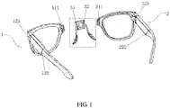
FIG. 1 is a schematic diagram of an exploded structure of a smart head-mounted device according to an embodiment of the present invention; -
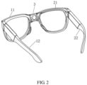
FIG. 2 is a schematic diagram of an integral structure of a smart head-mounted device according to an embodiment of the present invention; -
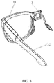
FIG. 3 is a schematic diagram of part of a structure of a smart head-mounted device according to an embodiment of the present invention; -
FIG. 4 is another schematic diagram of part of a structure of a smart head-mounted device according to an embodiment of the present invention; -
FIG. 5 is still another schematic diagram of part of a structure of a smart head-mounted device according to an embodiment of the present invention; -
FIG. 6 is a schematic diagram of disposing a wireless charging component in a smart head-mounted device according to an embodiment of the present invention; and -
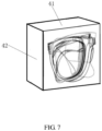
FIG. 7 is a schematic diagram of taking off a smart head-mounted device and putting the smart head-mounted device into an accommodating box according to an embodiment of the present invention. - To make the objectives, technical solutions, and advantages of the present invention clearer, the following clearly and completely describes the technical solutions in the embodiments of the present invention with reference to the accompanying drawings in the embodiments of the present invention. Apparently, the embodiments described are some rather than all of the embodiments of the present invention. Based on the embodiments of the present invention, all other embodiments obtained by a person of ordinary skill in the art without creative efforts fall within the protection scope of the present invention.
- As shown in
FIG. 1 , an embodiment of the present invention provides a smart head-mounted device. The smart head-mounted device includes a first sub-eyepiece 1, asecond sub-eyepiece 2, and anose bridge 3. The first sub-eyepiece 1 includes afirst eyepiece frame 11 and afirst temple 12, and thefirst eyepiece frame 11 has a first connectingportion 111. Thefirst temple 12 is provided with a first end and a second end that are disposed opposite each other, and the first end of thefirst temple 12 is connected to thefirst eyepiece frame 11. Thesecond sub-eyepiece 2 includes asecond eyepiece frame 21 and asecond temple 22, and thesecond eyepiece frame 21 has a second connectingportion 211. Thesecond temple 22 is provided with a first end and a second end that are disposed opposite each other, and the first end of thesecond temple 22 is connected to thesecond eyepiece frame 21. Thenose bridge 3 has a third connectingportion 31 and a fourth connectingportion 32. Thefirst eyepiece frame 11 is detachably connected to thenose bridge 3 via the first connectingportion 111 and the third connectingportion 31, and thesecond eyepiece frame 21 is detachably connected to thenose bridge 3 via the second connectingportion 211 and the fourth connectingportion 32. - As shown in
FIG. 2 , when thefirst eyepiece frame 11 is connected to thesecond eyepiece frame 21 via thenose bridge 3, thefirst temple 12 and thesecond temple 22 are symmetrically distributed on side edges that are of thefirst eyepiece frame 11 and thesecond eyepiece frame 21 and that are far away from each other, and side edges that are of thefirst eyepiece frame 11 and thesecond eyepiece frame 21 and that are close to each other are spliced via thenose bridge 3, where both joints between thenose bridge 3, and thefirst eyepiece frame 11 and thesecond eyepiece frame 21 are foldable. It may be understood that, thefirst eyepiece frame 11 and thesecond eyepiece frame 21 are each provided with an embedded lens, and can be separated to obtain two independent single eyepieces, respectively. As shown inFIG. 3 , the first sub-eyepiece 1 and thenose bridge 3 may constitute a first single eyepiece. As shown inFIG. 4 , thesecond sub-eyepiece 2 and thenose bridge 3 may constitute a second single eyepiece. In this way, the first single eyepiece can be used independently when thesecond sub-eyepiece 2 is being charged; and similarly, the second single eyepiece can be used independently when the first sub-eyepiece 1 is being charged. Therefore, the smart head-mounted device can resolve the following problems: An existing smart head-mounted device cannot be used when being charged, and cannot be charged when being used. In some emergency or special occasions, a user can just use any one of the first single eyepiece or the second single eyepiece. In this way, normal vision and emergency data communication interaction, such as recording sports data or providing Bluetooth calls, can be provided to at least one eye, thereby improving user experience. It should be understood that each of the first sub-eyepiece 1 and thesecond sub-eyepiece 2 is provided with an independent battery for supplying power. In addition, because both thefirst eyepiece frame 11 and thesecond eyepiece frame 21 are detachably connected to thenose bridge 3, the smart head-mounted device can be detached into three parts for accommodation, which may specifically be as follows: First, thefirst eyepiece frame 11, thesecond eyepiece frame 21, and thenose bridge 3 are all detached; then, the first sub-eyepiece 1 and thesecond sub-eyepiece 2 are overlapped and accommodated in an accommodating box; and thenose bridge 3 is independently put into the accommodating box. Therefore, compared with un-detachable smart glasses in the prior art, a size of the accommodating box in a length direction can be reduced by half approximately, which effectively improves portability of the smart head-mounted device. - In an embodiment, in a case that the
first eyepiece frame 11 is connected to thenose bridge 3, the first connectingportion 111 is in plug-in connection with the third connectingportion 31; or one of the first connectingportion 111 and the third connectingportion 31 is a magnetic member, and the other one is a magnetic attraction member, or both the first connectingportion 111 and the third connectingportion 31 are magnetic attraction members, and in a case that thefirst eyepiece frame 11 is connected to thenose bridge 3, the first connectingportion 111 is connected to the third connectingportion 31 via magnetic suction. - As shown in
FIG. 1 , the first connectingportion 111 of thefirst eyepiece frame 11 may be in plug-in connection with the third connectingportion 31 of thenose bridge 3. The plug-in connection may be unidirectional plug-in connection. For example, the first connectingportion 111 of thefirst eyepiece frame 11 is an insertion piece; and correspondingly, the third connectingportion 31 of thenose bridge 3 is a matched slot through which the first connectingportion 111 is inserted in and connected to the third connectingportion 31. Certainly, the first connectingportion 111 of thefirst eyepiece frame 11 may alternatively be a slot; and correspondingly, the third connectingportion 31 of thenose bridge 3 is a matched insertion piece through which the third connectingportion 31 is inserted in and connected to the first connectingportion 111. The plug-in connection may alternatively be bidirectional plug-in connection. For example, the first connectingportion 111 of thefirst eyepiece frame 11 is provided with a first insertion piece and a first slot, and correspondingly, the third connectingportion 31 of thenose bridge 3 is provided with a second slot and a second insertion piece, where the first insertion piece is in matched plug-in connection with the second slot, and the second insertion piece is in matched plug-in connection with the first slot. Further, optionally, the first connectingportion 111 of thefirst eyepiece frame 11 is a charging socket; and correspondingly, the accommodating box is provided with a matched charging interface inside. Therefore, when thefirst eyepiece frame 11 is detached from thenose bridge 3 and accommodated in the accommodating box, thefirst eyepiece frame 11 can perform plug-in charging with the accommodating box through the charging socket of the first connectingportion 111, thereby implementing wired charging of the first sub-eyepiece 1. - Alternatively, the first connecting
portion 111 of thefirst eyepiece frame 11 may be connected to the third connectingportion 31 of thenose bridge 3 via magnetic suction. Owing to magnetic suction, both connection and detaching are very convenient. Further, optionally, the first connectingportion 111 of thefirst eyepiece frame 11 is a magnetic charging interface; and correspondingly, the accommodating box is provided with a matched magnetic charging contact inside. Therefore, when thefirst eyepiece frame 11 is detached from thenose bridge 3 and accommodated in the accommodating box, thefirst eyepiece frame 11 can perform magnetic charging with the accommodating box through the magnetic charging interface of the first connectingportion 111, thereby implementing wired charging of the first sub-eyepiece 1. - In an embodiment, in a case that the
second eyepiece frame 21 is connected to thenose bridge 3, the second connectingportion 211 is in plug-in connection with the fourth connectingportion 32; or one of the second connectingportion 211 and the fourth connectingportion 32 is a magnetic member, and the other one is a magnetic attraction member, or both the second connectingportion 211 and the fourth connectingportion 32 are magnetic attraction members, and in a case that thesecond eyepiece frame 21 is connected to thenose bridge 3, the second connectingportion 211 is connected to the fourth connectingportion 32 via magnetic suction. - As shown in
FIG. 1 , the second connectingportion 211 of thesecond eyepiece frame 21 may be in plug-in connection with the fourth connectingportion 32 of thenose bridge 3. The plug-in connection may be unidirectional plug-in connection. For example, the second connectingportion 211 of thesecond eyepiece frame 21 is an insertion piece; and correspondingly, the fourth connectingportion 32 of thenose bridge 3 is a matched slot through which the second connectingportion 211 is inserted in and connected to the fourth connectingportion 32. Certainly, the second connectingportion 211 of thesecond eyepiece frame 21 may alternatively be a slot; and correspondingly, the fourth connectingportion 32 of thenose bridge 3 is a matched insertion piece through which the fourth connectingportion 32 is inserted in and connected to the second connectingportion 211. The plug-in connection may alternatively be bidirectional plug-in connection. For example, the second connectingportion 211 of thesecond eyepiece frame 21 is provided with a first insertion piece and a first slot, and correspondingly, the fourth connectingportion 32 of thenose bridge 3 is provided with a second slot and a second insertion piece, where the first insertion piece is in matched plug-in connection with the second slot, and the second insertion piece is in matched plug-in connection with the first slot. Further, optionally, the second connectingportion 211 of thesecond eyepiece frame 21 is a charging socket; and correspondingly, the accommodating box is provided with a matched charging interface inside. Therefore, when thesecond eyepiece frame 21 is detached from thenose bridge 3 and accommodated in the accommodating box, thesecond eyepiece frame 21 can perform plug-in charging with the accommodating box through the charging socket of the second connectingportion 211, thereby implementing wired charging of thesecond sub-eyepiece 2. - Alternatively, the second connecting
portion 211 of thesecond eyepiece frame 21 may be connected to the fourth connectingportion 32 of thenose bridge 3 via magnetic suction. Owing to magnetic suction, both connection and detaching are very convenient. Further, optionally, the second connectingportion 211 of thesecond eyepiece frame 21 is a magnetic charging interface; and correspondingly, the accommodating box is provided with a matched magnetic charging contact inside. Therefore, when thesecond eyepiece frame 21 is detached from thenose bridge 3 and accommodated in the accommodating box, thesecond eyepiece frame 21 can perform magnetic charging with the accommodating box through the magnetic charging interface of the second connectingportion 211, thereby implementing wired charging of thesecond sub-eyepiece 2. - As shown in
FIG. 1 , in an embodiment, thefirst temple 12 is provided with afirst folding portion 121 and asecond folding portion 122, thefirst folding portion 121 is disposed close to the first end of thefirst temple 12, and thesecond folding portion 122 is disposed between thefirst folding portion 121 and the second end of thefirst temple 12. - Owing to arrangement of the
first folding portion 121 and thesecond folding portion 122, thefirst temple 12 can be folded twice. Thefirst temple 12 is first folded along thesecond folding portion 122 and then folded along thefirst folding portion 121. Therefore, after twice folding, space occupied by thefirst eyepiece frame 11 and thefirst temple 12 during accommodation can be greatly reduced, thereby improving portability of the first sub-eyepiece 1. - In an embodiment, in a case that both the
first folding portion 121 and thesecond folding portion 122 are in a folded state, a first plane on which thefirst temple 12 is disposed is parallel to a second plane on which thefirst eyepiece frame 11 is disposed. - After the
first temple 12 is folded along thesecond folding portion 122 and thefirst folding portion 121, thefirst temple 12 and thefirst eyepiece frame 11 are parallel to each other. In this case, a thickness of the first sub-eyepiece 1 is relatively small, which facilitates carrying and accommodation. - Further, optionally, after the
first temple 12 is folded along thefirst folding portion 121 and thesecond folding portion 122, the second end of thefirst temple 12 does not exceed thefirst eyepiece frame 11. Therefore, after thefirst temple 12 is folded twice, a size of the entire first sub-eyepiece 1 is approximately as small as a size of thefirst eyepiece frame 11, so that the first sub-eyepiece 1 is smaller and more convenient to carry. - As shown in
FIG. 1 andFIG. 5 , in an embodiment, thesecond temple 22 is provided with athird folding portion 221 and afourth folding portion 222, thethird folding portion 221 is disposed close to the first end of thesecond temple 22, and thefourth folding portion 222 is disposed between thethird folding portion 221 and the second end of thesecond temple 22. - Owing to arrangement of the
third folding portion 221 and thefourth folding portion 222, thesecond temple 22 can be folded twice. Thesecond temple 22 is first folded along thefourth folding portion 222 and then folded along thethird folding portion 221. Therefore, after twice folding, space occupied by thesecond eyepiece frame 21 and thesecond temple 22 during accommodation can be greatly reduced, thereby improving portability of thesecond sub-eyepiece 2. - In an embodiment, in a case that both the
third folding portion 221 and thefourth folding portion 222 are in a folded state, a third plane on which thesecond temple 22 is disposed is parallel to a fourth plane on which thesecond eyepiece frame 21 is disposed. - After the
second temple 22 is folded along thefourth folding portion 222 and thethird folding portion 221, thesecond temple 22 and thesecond eyepiece frame 21 are parallel to each other. In this case, a thickness of the entiresecond sub-eyepiece 2 is relatively small, which facilitates carrying and accommodation. - Further, optionally, after the
second temple 22 is folded along thethird folding portion 221 and thefourth folding portion 222, the second end of thesecond temple 22 does not exceed thesecond eyepiece frame 21. Therefore, after thesecond temple 22 is folded twice, a size of the entiresecond sub-eyepiece 2 is approximately as small as a size of thesecond eyepiece frame 21, so that thesecond sub-eyepiece 2 is smaller and more convenient to carry. - In one embodiment, the first sub-eyepiece 1 and/or the
second sub-eyepiece 2 are/is provided with a wireless charging component. Further, optionally, in a case that the first sub-eyepiece 1 is provided with the wireless charging component, the wireless charging component is disposed on thefirst eyepiece frame 11 and/or thefirst temple 12; and in a case that thesecond sub-eyepiece 2 is provided with the wireless charging component, the wireless charging component is disposed on thesecond eyepiece frame 21 and/or thesecond temple 22. - The wireless charging component may be, for example, a wireless charging coil; and correspondingly, the accommodating box is also provided with a wireless charging coil inside. Therefore, wireless charging can be realized after the smart head-mounted device is put into the accommodating box.
- As shown in
FIG. 7 , an embodiment of the present invention further provides an accommodating box of a smart head-mounted device. The accommodating box includes ashell body 41 and acover body 42 movably connected to theshell body 41, where in a case that thecover body 42 covers theshell body 41, thecover body 42 and theshell body 41 are enclosed to form an accommodating space, the accommodating space is used to accommodate the smart head-mounted device described above, the accommodating space includes a first accommodating space, a second accommodating space, and a third accommodating space, the first accommodating space is used to accommodate the first sub-eyepiece 1 described above, the second accommodating space is used to accommodate thesecond sub-eyepiece 2 described above, and the third accommodating space is used to accommodate thenose bridge 3 described above. - Optionally, the
first eyepiece frame 11, thesecond eyepiece frame 21, and thenose bridge 3 are detached and separated; both thefirst temple 12 and thesecond temple 22 are folded twice; and then, the first sub-eyepiece 1, thesecond sub-eyepiece 2, and thenose bridge 3 that are separated and folded are put into the accommodating box. The two sub-eyepieces are overlapped front and back in a thickness direction of the accommodating box and disposed in the accommodating box, so that a size of the entire accommodating box is very small and exquisite, and the accommodating box is more convenient to carry. The accommodating box is provided with a first accommodating space, a second accommodating space, and a third accommodating space inside. The three accommodating cavities are independent of each other. The first accommodating space is used to accommodate the first sub-eyepiece 1, the second accommodating space is used to accommodate thesecond sub-eyepiece 2, and the third accommodating space is used to accommodate thenose bridge 3. In this way, all of the first sub-eyepiece 1, thesecond sub-eyepiece 2, and thenose bridge 3 can be accommodated in a relatively independent manner, which avoids squeezing contact during accommodation of the first sub-eyepiece 1, thesecond sub-eyepiece 2, and thenose bridge 3. - In an embodiment, the first sub-eyepiece 1 is provided with a first magnet, the
second sub-eyepiece 2 is provided with a second magnet, thenose bridge 3 is provided with a third magnet, the first accommodating space is provided with a first Hall sensor, the second accommodating space is provided with a second Hall sensor, and the third accommodating space is provided with a third Hall sensor. In a case that the first sub-eyepiece 1 is accommodated in the first accommodating space, the first magnet and the first Hall sensor are distributed opposite each other; in a case that thesecond sub-eyepiece 2 is accommodated in the second accommodating space, the second magnet and the second Hall sensor are distributed opposite each other; and in a case that thenose bridge 3 is accommodated in the third accommodating space, the third magnet and the third Hall sensor are distributed opposite each other. - In one embodiment, at least one of the
shell body 41 and thecover body 42 is provided with a controller and an alarm, the controller is electrically connected to the first Hall sensor, the second Hall sensor, and the third Hall sensor, and the controller is further electrically connected to the alarm. - Loss may occur if the smart head-mounted device is not accommodated in time after being detached. Therefore, in this embodiment, the accommodating box is provided with an anti-loss function. Specifically, for example, when both the first sub-eyepiece 1 and the
second sub-eyepiece 2 are put into the accommodating box, but thenose bridge 3 is not put into the accommodating box, the first Hall sensor can detect the first magnet and sends a detection signal to a controller after the first sub-eyepiece 1 is put into the first accommodating space; the second Hall sensor can detect the second magnet and sends a detection signal to the controller after thesecond sub-eyepiece 2 is put into the second accommodating space; and because thenose bridge 3 is not put into the third accommodating space, the third Hall sensor fails to detect the third magnet and does not send a detection signal to the controller. In this case, the controller triggers an alarm. Optionally, the alarm is an acousto-optic alarm. For another example, when both the first sub-eyepiece 1 and thenose bridge 3 are put into the accommodating box, but thesecond sub-eyepiece 2 is not put into the accommodating box, the first Hall sensor can detect the first magnet and sends a detection signal to a controller after the first sub-eyepiece 1 is put into the first accommodating space; the third Hall sensor can detect the third magnet and sends a detection signal to the controller after thenose bridge 3 is put into the third accommodating space; and because thesecond sub-eyepiece 2 is not put into the second accommodating space, the second Hall sensor fails to detect the second magnet and does not send a detection signal to the controller. In this case, the controller triggers the alarm. Other cases have a same principle. Details are not described herein again. In other words, the controller triggers the alarm, provided that any one or two of the first Hall sensor, the second Hall sensor, and the third Hall sensor send detection signals to the controller and the other two or one does not send a detection signal to the controller. Certainly, there may be no controller, and the first Hall sensor, the second Hall sensor, and the third Hall sensor are connected to a trigger switch of the alarm. Therefore, a same effect can be achieved. - In an embodiment, the first accommodating space is provided with a fifth connecting portion, and in a case that the first sub-eyepiece 1 is accommodated in the first accommodating space, the first connecting
portion 111 is connected to the fifth connecting portion; the second accommodating space is provided with a sixth connecting portion, and in a case that thesecond sub-eyepiece 2 is accommodated in the second accommodating space, the second connectingportion 211 is connected to the sixth connecting portion; and the third accommodating space is provided with a seventh connecting portion, and in a case that thenose bridge 3 is accommodated in the third accommodating space, at least one of the third connectingportion 31 and the fourth connectingportion 32 is connected to the seventh connecting portion. - Optionally, the first connecting
portion 111 and the fifth connecting portion are electric connecting portions matched with each other, so that in a case that the first sub-eyepiece 1 is accommodated in the first accommodating space, the first connectingportion 111 and the fifth connecting portion are electrically connected to each other, thereby implementing charging the first sub-eyepiece 1 by the accommodating box. Similarly, the second connectingportion 211 and the sixth connecting portion are electric connecting portions matched with each other, so that in a case that thesecond sub-eyepiece 2 is accommodated in the second accommodating space, the second connectingportion 211 and the sixth connecting portion are electrically connected to each other, thereby implementing charging thesecond sub-eyepiece 2 by the accommodating box. In addition, the seventh connecting portion and at least one of the third connectingportion 31 and the fourth connectingportion 32 are electric connecting portions matched with each other, so that in a case that thenose bridge 3 is accommodated in the third accommodating space, at least one of the third connectingportion 31 and the fourth connectingportion 32 is electrically connected to the seventh connecting portion. Therefore, fixing thenose bridge 3 can be implemented; and some expanding functions of thenose bridge 3 can also be implemented, for example, thenose bridge 3 is provided with a chip, thereby performing interacting with the accommodating box. - As shown in
FIG. 6 , in one embodiment, the first sub-eyepiece 1 is provided with a firstwireless charging component 13; and thesecond sub-eyepiece 2 is provided with a secondwireless charging component 23. The first accommodating space is provided with a third wireless charging component, and the second accommodating space is provided with a fourth wireless charging component. In a case that the first sub-eyepiece 1 is accommodated in the first accommodating space, the firstwireless charging component 13 and the third wireless charging component are distributed opposite each other. In a case that thesecond sub-eyepiece 2 is accommodated in the second accommodating space, the secondwireless charging component 23 and the fourth wireless charging component are distributed opposite each other. - As the third wireless charging component distributed opposite the first
wireless charging component 13 is disposed in the first accommodating space, in a case that the first sub-eyepiece 1 is accommodated in the first accommodating space, wireless charging of the first sub-eyepiece 1 by the accommodating box is implemented. Similarly, as the fourth wireless charging component distributed opposite the secondwireless charging component 23 is disposed in the second accommodating space, in a case that thesecond sub-eyepiece 2 is accommodated in the second accommodating space, wireless charging of thesecond sub-eyepiece 2 by the accommodating box is implemented. - An embodiment of the present invention further provides a smart head-mounted device assembly, including the smart head-mounted device described above and the accommodating box described above.
- In the accompanying drawings of the embodiments, the same or similar reference numerals denote the same or similar components. In the description of the present invention, it should be understood that orientations or position relationships indicated by terms such as "upper", "lower", "left", "right", "inside", or "outside" are orientations or position relationships shown in the accompanying drawings, and these terms are just used to facilitate description of the present invention and simplify the description, but not to indicate or imply that the mentioned apparatuses or elements must have a specific orientation or must be constructed and operated in a specific orientation. Therefore, the terms for describing position relationships in the accompanying drawings are only for illustrative description but should not be construed as a limitation to the present invention. A person of ordinary skill in the art may interpret the specific meaning of the above terms according to specific conditions.
- It should be noted that, in this specification, the terms "include", "comprise", or any of their variants are intended to cover a non-exclusive inclusion, so that a process, a method, an article, or an apparatus that includes a series of elements includes not only those elements but also other elements that are not expressly listed, or further includes elements inherent to such a process, method, article, or apparatus. In the absence of more restrictions, an element defined by "including a ..." does not exclude another same element in a process, method, article, or apparatus that includes the element.
- The embodiments of the present invention are described above with reference to the accompanying drawings, but the present invention is not limited to the above specific implementations, and the above specific implementations are only illustrative and not restrictive. Under the enlightenment of the present invention, a person of ordinary skill in the art can make many forms without departing from the objective of the present invention and the protection scope of the claims, all of which fall within the protection of the present invention.
Claims (14)
- A smart head-mounted device, comprising a first sub-eyepiece (1), a second sub-eyepiece (2), and a nose bridge (3), whereinthe first sub-eyepiece (1) comprises:a first eyepiece frame (11), wherein the first eyepiece frame (11) has a first connecting portion (111); anda first temple (12), wherein the first temple (12) has a first end and a second end that are disposed opposite each other, and the first end of the first temple (12) is connected to the first eyepiece frame (11);the second sub-eyepiece (2) comprises:a second eyepiece frame (21), wherein the second eyepiece frame (21) has a second connecting portion (211); anda second temple (22), wherein the second temple (22) has a first end and a second end that are disposed opposite each other, and the first end of the second temple (22) is connected to the second eyepiece frame (21);the nose bridge (3) has a third connecting portion (31) and a fourth connecting portion (32); andthe first eyepiece frame (11) is detachably connected to the nose bridge (3) via the first connecting portion (111) and the third connecting portion (31), and the second eyepiece frame (21) is detachably connected to the nose bridge (3) via the second connecting portion (211) and the fourth connecting portion (32).
- The smart head-mounted device according to claim 1, wherein in a case that the first eyepiece frame (11) is connected to the nose bridge (3), the first connecting portion (111) is in plug-in connection with the third connecting portion (31); or
one of the first connecting portion (111) and the third connecting portion (31) is a magnetic member, and another of the first connecting portion (111) and the third connecting portion (31) is a magnetic attraction member, or both the first connecting portion (111) and the third connecting portion (31) are magnetic attraction members, and in a case that the first eyepiece frame (11) is connected to the nose bridge (3), the first connecting portion (111) is connected to the third connecting portion (31) via magnetic suction. - The smart head-mounted device according to claim 1, wherein in a case that the second eyepiece frame (21) is connected to the nose bridge (3), the second connecting portion (211) is in plug-in connection with the fourth connecting portion (32); or
one of the second connecting portion (211) and the fourth connecting portion (32) is a magnetic member, and the other one is a magnetic attraction member, or both the second connecting portion (211) and the fourth connecting portion (32) are magnetic attraction members, and in a case that the second eyepiece frame (21) is connected to the nose bridge (3), the second connecting portion (211) is connected to the fourth connecting portion (32) via magnetic suction. - The smart head-mounted device according to claim 1, wherein the first temple (12) comprises a first folding portion (121) and a second folding portion (122), the first folding portion (121) is disposed close to the first end of the first temple (12), and the second folding portion (122) is disposed between the first folding portion (121) and the second end of the first temple (12).
- The smart head-mounted device according to claim 4, wherein in a case that both the first folding portion (121) and the second folding portion (122) are in a folded state, a first plane on which the first temple (12) is disposed is parallel to a second plane on which the first eyepiece frame (11) is disposed.
- The smart head-mounted device according to claim 1, wherein the second temple (22) comprises a third folding portion (221) and a fourth folding portion (222), the third folding portion (221) is disposed close to the first end of the second temple (22), and the fourth folding portion (222) is disposed between the third folding portion (221) and the second end of the second temple (22).
- The smart head-mounted device according to claim 6, wherein in a case that both the third folding portion (221) and the fourth folding portion (222) are in a folded state, a third plane on which the second temple (22) is disposed is parallel to a fourth plane on which the second eyepiece frame (21) is disposed.
- The smart head-mounted device according to claim 1, wherein the first sub-eyepiece (1) and/or the second sub-eyepiece (2) is provided with a wireless charging component.
- An accommodating box of a smart head-mounted device, comprising a shell body (41) and a cover body (42) movably connected to the shell body (41), wherein in a case that the cover body (42) covers the shell body (41), the cover body (42) and the shell body (41) are enclosed to form an accommodating space, the accommodating space is used to accommodate the smart head-mounted device according to any one of claims 1 to 8, the accommodating space comprises a first accommodating space, a second accommodating space, and a third accommodating space, the first accommodating space is used to accommodate the first sub-eyepiece (1), the second accommodating space is used to accommodate the second sub-eyepiece (2), and the third accommodating space is used to accommodate the nose bridge (3).
- The accommodating box according to claim 9, wherein the first sub-eyepiece (1) is provided with a first magnet, the second sub-eyepiece (2) is provided with a second magnet, the nose bridge (3) is provided with a third magnet, the first accommodating space is provided with a first Hall sensor, the second accommodating space is provided with a second Hall sensor, and the third accommodating space is provided with a third Hall sensor;in a case that the first sub-eyepiece (1) is accommodated in the first accommodating space, the first magnet and the first Hall sensor are distributed opposite each other;in a case that the second sub-eyepiece (2) is accommodated in the second accommodating space, the second magnet and the second Hall sensor are distributed opposite each other; andin a case that the nose bridge (3) is accommodated in the third accommodating space, the third magnet and the third Hall sensor are distributed opposite each other.
- The accommodating box according to claim 10, wherein at least one of the shell body (41) and the cover body (42) is provided with a controller and an alarm, the controller is electrically connected to the first Hall sensor, the second Hall sensor, and the third Hall sensor, and the controller is further electrically connected to the alarm.
- The accommodating box according to claim 9, wherein the first accommodating space is provided with a fifth connecting portion, and in a case that the first sub-eyepiece (1) is accommodated in the first accommodating space, the first connecting portion (111) is connected to the fifth connecting portion;the second accommodating space is provided with a sixth connecting portion, and in a case that the second sub-eyepiece (2) is accommodated in the second accommodating space, the second connecting portion (211) is connected to the sixth connecting portion; andthe third accommodating space is provided with a seventh connecting portion, and in a case that the nose bridge (3) is accommodated in the third accommodating space, at least one of the third connecting portion (31) and the fourth connecting portion (32) is connected to the seventh connecting portion.
- The accommodating box according to claim 9, wherein the first sub-eyepiece (1) is provided with a first wireless charging component (13), the second sub-eyepiece (2) is provided with a second wireless charging component (23), the first accommodating space is provided with a third wireless charging component, and the second accommodating space is provided with a fourth wireless charging component;in a case that the first sub-eyepiece (1) is accommodated in the first accommodating space, the first wireless charging component (13) and the third wireless charging component are distributed opposite each other; andin a case that the second sub-eyepiece (2) is accommodated in the second accommodating space, the second wireless charging component (23) and the fourth wireless charging component are distributed opposite each other.
- A smart head-mounted device assembly, comprising the smart head-mounted device according to any one of claims 1 to 8 and the accommodating box according to any one of claims 9 to 13.
Applications Claiming Priority (2)
| Application Number | Priority Date | Filing Date | Title |
|---|---|---|---|
| CN202010490086.6A CN111708164B (en) | 2020-06-02 | 2020-06-02 | Intelligence head-mounted apparatus, receiver and intelligent head-mounted apparatus subassembly |
| PCT/CN2021/095941 WO2021244361A1 (en) | 2020-06-02 | 2021-05-26 | Intelligent head-mounted device, storage box, and intelligent head-mounted device assembly |
Publications (3)
| Publication Number | Publication Date |
|---|---|
| EP4160297A1 true EP4160297A1 (en) | 2023-04-05 |
| EP4160297A4 EP4160297A4 (en) | 2023-11-15 |
| EP4160297B1 EP4160297B1 (en) | 2026-01-28 |
Family
ID=72538460
Family Applications (1)
| Application Number | Title | Priority Date | Filing Date |
|---|---|---|---|
| EP21817349.0A Active EP4160297B1 (en) | 2020-06-02 | 2021-05-26 | Intelligent head-mounted device, storage box, and intelligent head-mounted device assembly |
Country Status (4)
| Country | Link |
|---|---|
| US (1) | US12474601B2 (en) |
| EP (1) | EP4160297B1 (en) |
| CN (1) | CN111708164B (en) |
| WO (1) | WO2021244361A1 (en) |
Families Citing this family (5)
| Publication number | Priority date | Publication date | Assignee | Title |
|---|---|---|---|---|
| CN111708164B (en) | 2020-06-02 | 2022-03-25 | 维沃移动通信有限公司 | Intelligence head-mounted apparatus, receiver and intelligent head-mounted apparatus subassembly |
| CN113359302A (en) * | 2021-06-29 | 2021-09-07 | 歌尔科技有限公司 | Control method and device of intelligent glasses legs and computer readable storage medium |
| CN116360100A (en) * | 2021-12-28 | 2023-06-30 | Oppo广东移动通信有限公司 | Augmented reality device and intelligent glasses |
| US20260079357A1 (en) * | 2022-03-24 | 2026-03-19 | Apple Inc. | Adjustable head-mounted device |
| US20240231122A9 (en) * | 2022-10-19 | 2024-07-11 | AJsens Inc. | Detachable Three-Piece Eyeglasses Suitable for Single Eyewear |
Family Cites Families (27)
| Publication number | Priority date | Publication date | Assignee | Title |
|---|---|---|---|---|
| US2446966A (en) * | 1945-04-20 | 1948-08-10 | Plastal Corp | Spectacle case |
| US6164452A (en) * | 1999-03-19 | 2000-12-26 | Ellis; Robert | Personal optical care container |
| US6164442A (en) * | 1999-08-19 | 2000-12-26 | Stravitz; David M. | Multi-part, multi-fold, multi-compartment portable carrying and storage case |
| US20050016882A1 (en) * | 2003-07-07 | 2005-01-27 | Ravindra Kankaria | Optometric trial lens set apparatus and method |
| US11644693B2 (en) * | 2004-07-28 | 2023-05-09 | Ingeniospec, Llc | Wearable audio system supporting enhanced hearing support |
| TWM296990U (en) * | 2006-03-24 | 2006-09-01 | Yung-Ming Huang | Foldable eye glasses |
| CN202522773U (en) * | 2011-11-22 | 2012-11-07 | 王苏元 | Folding glasses capable of automatically popping out |
| US10234699B2 (en) | 2013-11-26 | 2019-03-19 | Sony Corporation | Head-mounted display |
| US9625741B1 (en) * | 2014-09-29 | 2017-04-18 | Joseph Tammaro | Removable clip-on lenses |
| TWM506974U (en) * | 2015-04-24 | 2015-08-11 | Universal Vision Biotechnology Co Ltd | Wireless charging head mounted display device |
| CN105572909A (en) * | 2016-02-05 | 2016-05-11 | 深圳市慧明眼镜有限公司 | Multifunctional changeable spectacles convenient to disassemble |
| US10042187B2 (en) * | 2016-02-29 | 2018-08-07 | Snap Inc. | Heat management for electronic devices |
| CN105938248A (en) * | 2016-05-12 | 2016-09-14 | 深圳增强现实技术有限公司 | User-friendly fixing system used for augmented reality intelligent glasses |
| DE202016103431U1 (en) * | 2016-06-28 | 2016-07-27 | Frank Fischer | Case for storage of at least two glasses |
| CN108065548A (en) * | 2016-11-15 | 2018-05-25 | 四川省广安恒升中学校 | A kind of glasses case for student |
| CN107647659B (en) * | 2017-10-17 | 2020-04-07 | 深圳市中建旭展广告有限公司 | Intelligent VR experiences equipment with accomodate function |
| CN208046851U (en) * | 2018-03-16 | 2018-11-02 | 北京纽曼凤凰科技有限公司 | Bluetooth headset storage device |
| WO2019198875A1 (en) * | 2018-04-13 | 2019-10-17 | 임성규 | Self-customized glasses |
| CN209821503U (en) * | 2019-03-12 | 2019-12-20 | 杭州历历信息科技有限公司 | Intelligent glasses and glasses legs, glasses frame and intelligent glasses system thereof |
| CN118311787A (en) * | 2019-03-25 | 2024-07-09 | 华为技术有限公司 | Glasses with wireless charging receiving circuit, glasses case and system for glasses |
| EP3952336A4 (en) * | 2019-04-30 | 2022-05-18 | Shenzhen Shokz Co., Ltd. | Acoustic output apparatus |
| CN209879169U (en) * | 2019-06-04 | 2019-12-31 | 杭州职业技术学院 | Detachable glasses structure |
| CN110989197A (en) * | 2019-12-30 | 2020-04-10 | 歌尔科技有限公司 | smart glasses |
| CN110927988A (en) * | 2019-12-31 | 2020-03-27 | 歌尔科技有限公司 | Adjustable glasses of wearing |
| US11444488B2 (en) * | 2020-05-28 | 2022-09-13 | Microsoft Technology Licensing, Llc | Wireless charging for optical device |
| CN111708164B (en) * | 2020-06-02 | 2022-03-25 | 维沃移动通信有限公司 | Intelligence head-mounted apparatus, receiver and intelligent head-mounted apparatus subassembly |
| CN111568013B (en) * | 2020-06-28 | 2022-10-18 | Oppo广东移动通信有限公司 | Glasses Cases and Smart Glasses |
-
2020
- 2020-06-02 CN CN202010490086.6A patent/CN111708164B/en active Active
-
2021
- 2021-05-26 EP EP21817349.0A patent/EP4160297B1/en active Active
- 2021-05-26 WO PCT/CN2021/095941 patent/WO2021244361A1/en not_active Ceased
-
2022
- 2022-12-01 US US18/073,163 patent/US12474601B2/en active Active
Also Published As
| Publication number | Publication date |
|---|---|
| US20230094296A1 (en) | 2023-03-30 |
| EP4160297B1 (en) | 2026-01-28 |
| WO2021244361A1 (en) | 2021-12-09 |
| CN111708164B (en) | 2022-03-25 |
| US12474601B2 (en) | 2025-11-18 |
| EP4160297A4 (en) | 2023-11-15 |
| CN111708164A (en) | 2020-09-25 |
Similar Documents
| Publication | Publication Date | Title |
|---|---|---|
| US12474601B2 (en) | Smart head-mounted device, accommodating box, and smart head-mounted device assembly | |
| US11988843B2 (en) | Wearable device, battery used in the same, and power supply system | |
| US12189421B2 (en) | Eyewear with conductive temple joint | |
| CN209821503U (en) | Intelligent glasses and glasses legs, glasses frame and intelligent glasses system thereof | |
| WO2021022994A1 (en) | Smart glasses and glasses kit | |
| CN105242411A (en) | Split-type intelligent glasses | |
| US20240291301A1 (en) | Smart Glasses, Charger, and Smart Glasses Assembly | |
| US11537029B2 (en) | Gimbal handle and gimbal having same | |
| US20240103303A1 (en) | Electronic charging system | |
| CN213464085U (en) | Intelligent glasses assembly | |
| EP4261595A1 (en) | Eyeglasses frame and smart eyeglasses | |
| CN212321983U (en) | A smart head mounted device, storage box and smart head mounted device assembly | |
| CN212784840U (en) | Placement box, wearable equipment and wearable equipment assembly | |
| CN111679433A (en) | A smart head-mounted device | |
| US20240275210A1 (en) | Hmd with charging device | |
| CN217821136U (en) | Glasses assembly and intelligent glasses | |
| US20260099064A1 (en) | Smart glass including a detachable temple part | |
| CN222070986U (en) | Glasses with glasses | |
| CN212752344U (en) | Be applied to electronic equipment's protective housing subassembly | |
| CN222580549U (en) | Portable device, electronic device kit and wearable device kit | |
| CN216118269U (en) | A currency auxiliary module applied to stereo vision multi-mode blind glasses | |
| KR20230147205A (en) | Wearable members, wearable devices and charging systems | |
| CN117748637A (en) | Electronic charging system | |
| CN120085465A (en) | Smart glasses | |
| CN114690417A (en) | Intelligent glasses and charging system |
Legal Events
| Date | Code | Title | Description |
|---|---|---|---|
| STAA | Information on the status of an ep patent application or granted ep patent |
Free format text: STATUS: THE INTERNATIONAL PUBLICATION HAS BEEN MADE |
|
| PUAI | Public reference made under article 153(3) epc to a published international application that has entered the european phase |
Free format text: ORIGINAL CODE: 0009012 |
|
| STAA | Information on the status of an ep patent application or granted ep patent |
Free format text: STATUS: REQUEST FOR EXAMINATION WAS MADE |
|
| 17P | Request for examination filed |
Effective date: 20221223 |
|
| AK | Designated contracting states |
Kind code of ref document: A1 Designated state(s): AL AT BE BG CH CY CZ DE DK EE ES FI FR GB GR HR HU IE IS IT LI LT LU LV MC MK MT NL NO PL PT RO RS SE SI SK SM TR |
|
| DAV | Request for validation of the european patent (deleted) | ||
| DAX | Request for extension of the european patent (deleted) | ||
| A4 | Supplementary search report drawn up and despatched |
Effective date: 20231013 |
|
| RIC1 | Information provided on ipc code assigned before grant |
Ipc: A45C 11/04 20060101ALI20231009BHEP Ipc: G02C 5/08 20060101ALI20231009BHEP Ipc: G02B 27/01 20060101AFI20231009BHEP |
|
| GRAP | Despatch of communication of intention to grant a patent |
Free format text: ORIGINAL CODE: EPIDOSNIGR1 |
|
| STAA | Information on the status of an ep patent application or granted ep patent |
Free format text: STATUS: GRANT OF PATENT IS INTENDED |
|
| INTG | Intention to grant announced |
Effective date: 20251006 |
|
| GRAS | Grant fee paid |
Free format text: ORIGINAL CODE: EPIDOSNIGR3 |
|
| GRAA | (expected) grant |
Free format text: ORIGINAL CODE: 0009210 |
|
| STAA | Information on the status of an ep patent application or granted ep patent |
Free format text: STATUS: THE PATENT HAS BEEN GRANTED |
|
| AK | Designated contracting states |
Kind code of ref document: B1 Designated state(s): AL AT BE BG CH CY CZ DE DK EE ES FI FR GB GR HR HU IE IS IT LI LT LU LV MC MK MT NL NO PL PT RO RS SE SI SK SM TR |
|
| REG | Reference to a national code |
Ref country code: CH Ref legal event code: F10 Free format text: ST27 STATUS EVENT CODE: U-0-0-F10-F00 (AS PROVIDED BY THE NATIONAL OFFICE) Effective date: 20260128 Ref country code: GB Ref legal event code: FG4D |
|
| REG | Reference to a national code |
Ref country code: DE Ref legal event code: R096 Ref document number: 602021047097 Country of ref document: DE |
|
| REG | Reference to a national code |
Ref country code: IE Ref legal event code: FG4D |
|
| PGFP | Annual fee paid to national office [announced via postgrant information from national office to epo] |
Ref country code: GB Payment date: 20260324 Year of fee payment: 6 |