EP4160289A1 - Integrated optical circulators enabling polarization diversity - Google Patents
Integrated optical circulators enabling polarization diversity Download PDFInfo
- Publication number
- EP4160289A1 EP4160289A1 EP22208787.6A EP22208787A EP4160289A1 EP 4160289 A1 EP4160289 A1 EP 4160289A1 EP 22208787 A EP22208787 A EP 22208787A EP 4160289 A1 EP4160289 A1 EP 4160289A1
- Authority
- EP
- European Patent Office
- Prior art keywords
- optical
- optical signal
- signal component
- port
- polarization
- Prior art date
- Legal status (The legal status is an assumption and is not a legal conclusion. Google has not performed a legal analysis and makes no representation as to the accuracy of the status listed.)
- Granted
Links
Images

Classifications
-
- G—PHYSICS
- G02—OPTICS
- G02B—OPTICAL ELEMENTS, SYSTEMS OR APPARATUS
- G02B6/00—Light guides; Structural details of arrangements comprising light guides and other optical elements, e.g. couplings
- G02B6/24—Coupling light guides
- G02B6/26—Optical coupling means
- G02B6/27—Optical coupling means with polarisation selective and adjusting means
- G02B6/2706—Optical coupling means with polarisation selective and adjusting means as bulk elements, i.e. free space arrangements external to a light guide, e.g. polarising beam splitters
- G02B6/2713—Optical coupling means with polarisation selective and adjusting means as bulk elements, i.e. free space arrangements external to a light guide, e.g. polarising beam splitters cascade of polarisation selective or adjusting operations
- G02B6/272—Optical coupling means with polarisation selective and adjusting means as bulk elements, i.e. free space arrangements external to a light guide, e.g. polarising beam splitters cascade of polarisation selective or adjusting operations comprising polarisation means for beam splitting and combining
-
- G—PHYSICS
- G02—OPTICS
- G02B—OPTICAL ELEMENTS, SYSTEMS OR APPARATUS
- G02B27/00—Optical systems or apparatus not provided for by any of the groups G02B1/00 - G02B26/00, G02B30/00
- G02B27/09—Beam shaping, e.g. changing the cross-sectional area, not otherwise provided for
- G02B27/0938—Using specific optical elements
- G02B27/0977—Reflective elements
-
- G—PHYSICS
- G02—OPTICS
- G02B—OPTICAL ELEMENTS, SYSTEMS OR APPARATUS
- G02B27/00—Optical systems or apparatus not provided for by any of the groups G02B1/00 - G02B26/00, G02B30/00
- G02B27/28—Optical systems or apparatus not provided for by any of the groups G02B1/00 - G02B26/00, G02B30/00 for polarising
- G02B27/283—Optical systems or apparatus not provided for by any of the groups G02B1/00 - G02B26/00, G02B30/00 for polarising used for beam splitting or combining
-
- G—PHYSICS
- G02—OPTICS
- G02B—OPTICAL ELEMENTS, SYSTEMS OR APPARATUS
- G02B5/00—Optical elements other than lenses
- G02B5/30—Polarising elements
- G02B5/3083—Birefringent or phase retarding elements
-
- G—PHYSICS
- G02—OPTICS
- G02B—OPTICAL ELEMENTS, SYSTEMS OR APPARATUS
- G02B6/00—Light guides; Structural details of arrangements comprising light guides and other optical elements, e.g. couplings
- G02B6/10—Light guides; Structural details of arrangements comprising light guides and other optical elements, e.g. couplings of the optical waveguide type
- G02B6/105—Light guides; Structural details of arrangements comprising light guides and other optical elements, e.g. couplings of the optical waveguide type having optical polarisation effects
-
- G—PHYSICS
- G02—OPTICS
- G02B—OPTICAL ELEMENTS, SYSTEMS OR APPARATUS
- G02B6/00—Light guides; Structural details of arrangements comprising light guides and other optical elements, e.g. couplings
- G02B6/10—Light guides; Structural details of arrangements comprising light guides and other optical elements, e.g. couplings of the optical waveguide type
- G02B6/12—Light guides; Structural details of arrangements comprising light guides and other optical elements, e.g. couplings of the optical waveguide type of the integrated circuit kind
- G02B6/126—Light guides; Structural details of arrangements comprising light guides and other optical elements, e.g. couplings of the optical waveguide type of the integrated circuit kind using polarisation effects
-
- G—PHYSICS
- G02—OPTICS
- G02B—OPTICAL ELEMENTS, SYSTEMS OR APPARATUS
- G02B6/00—Light guides; Structural details of arrangements comprising light guides and other optical elements, e.g. couplings
- G02B6/24—Coupling light guides
- G02B6/26—Optical coupling means
- G02B6/27—Optical coupling means with polarisation selective and adjusting means
- G02B6/2753—Optical coupling means with polarisation selective and adjusting means characterised by their function or use, i.e. of the complete device
- G02B6/2773—Polarisation splitting or combining
-
- G—PHYSICS
- G02—OPTICS
- G02F—OPTICAL DEVICES OR ARRANGEMENTS FOR THE CONTROL OF LIGHT BY MODIFICATION OF THE OPTICAL PROPERTIES OF THE MEDIA OF THE ELEMENTS INVOLVED THEREIN; NON-LINEAR OPTICS; FREQUENCY-CHANGING OF LIGHT; OPTICAL LOGIC ELEMENTS; OPTICAL ANALOGUE/DIGITAL CONVERTERS
- G02F1/00—Devices or arrangements for the control of the intensity, colour, phase, polarisation or direction of light arriving from an independent light source, e.g. switching, gating or modulating; Non-linear optics
- G02F1/01—Devices or arrangements for the control of the intensity, colour, phase, polarisation or direction of light arriving from an independent light source, e.g. switching, gating or modulating; Non-linear optics for the control of the intensity, phase, polarisation or colour
- G02F1/09—Devices or arrangements for the control of the intensity, colour, phase, polarisation or direction of light arriving from an independent light source, e.g. switching, gating or modulating; Non-linear optics for the control of the intensity, phase, polarisation or colour based on magneto-optical elements, e.g. exhibiting Faraday effect
- G02F1/093—Devices or arrangements for the control of the intensity, colour, phase, polarisation or direction of light arriving from an independent light source, e.g. switching, gating or modulating; Non-linear optics for the control of the intensity, phase, polarisation or colour based on magneto-optical elements, e.g. exhibiting Faraday effect used as non-reciprocal devices, e.g. optical isolators, circulators
-
- G—PHYSICS
- G02—OPTICS
- G02B—OPTICAL ELEMENTS, SYSTEMS OR APPARATUS
- G02B6/00—Light guides; Structural details of arrangements comprising light guides and other optical elements, e.g. couplings
- G02B6/24—Coupling light guides
- G02B6/26—Optical coupling means
- G02B6/27—Optical coupling means with polarisation selective and adjusting means
-
- G—PHYSICS
- G02—OPTICS
- G02B—OPTICAL ELEMENTS, SYSTEMS OR APPARATUS
- G02B6/00—Light guides; Structural details of arrangements comprising light guides and other optical elements, e.g. couplings
- G02B6/24—Coupling light guides
- G02B6/26—Optical coupling means
- G02B6/27—Optical coupling means with polarisation selective and adjusting means
- G02B6/2746—Optical coupling means with polarisation selective and adjusting means comprising non-reciprocal devices, e.g. isolators, FRM, circulators, quasi-isolators
-
- G—PHYSICS
- G02—OPTICS
- G02B—OPTICAL ELEMENTS, SYSTEMS OR APPARATUS
- G02B6/00—Light guides; Structural details of arrangements comprising light guides and other optical elements, e.g. couplings
- G02B6/24—Coupling light guides
- G02B6/26—Optical coupling means
- G02B6/27—Optical coupling means with polarisation selective and adjusting means
- G02B6/2753—Optical coupling means with polarisation selective and adjusting means characterised by their function or use, i.e. of the complete device
- G02B6/2766—Manipulating the plane of polarisation from one input polarisation to another output polarisation, e.g. polarisation rotators, linear to circular polarisation converters
-
- G—PHYSICS
- G02—OPTICS
- G02B—OPTICAL ELEMENTS, SYSTEMS OR APPARATUS
- G02B6/00—Light guides; Structural details of arrangements comprising light guides and other optical elements, e.g. couplings
- G02B6/24—Coupling light guides
- G02B6/42—Coupling light guides with opto-electronic elements
- G02B6/4201—Packages, e.g. shape, construction, internal or external details
- G02B6/4204—Packages, e.g. shape, construction, internal or external details the coupling comprising intermediate optical elements, e.g. lenses, holograms
- G02B6/4213—Packages, e.g. shape, construction, internal or external details the coupling comprising intermediate optical elements, e.g. lenses, holograms the intermediate optical elements being polarisation selective optical elements
-
- G—PHYSICS
- G02—OPTICS
- G02B—OPTICAL ELEMENTS, SYSTEMS OR APPARATUS
- G02B6/00—Light guides; Structural details of arrangements comprising light guides and other optical elements, e.g. couplings
- G02B6/24—Coupling light guides
- G02B6/42—Coupling light guides with opto-electronic elements
- G02B6/4201—Packages, e.g. shape, construction, internal or external details
- G02B6/4246—Bidirectionally operating package structures
Definitions
- Bi-directional communication where the upstream and downstream signals are running inside a single fiber, is an effective way to reduce the number of fibers used in a fiber-optic communication network.
- the key for implementing such bi-directional communications is to effectively separate and combine the upstream and downstream signals.
- One approach to separating and combining upstream and downstream signals is to add optical circulators to each end of a fiber.
- At least one aspect is directed to an integrated optical circulator enabling polarization diversity.
- the integrated optical circulator includes a first port configured to receive a first optical signal.
- the integrated optical circulator includes a second port configured to transmit the first optical signal received at the first port and also configured to receive a second optical signal.
- the integrated optical circulator includes a first polarizing beam splitter configured to receive the second optical signal, split the second optical signal into a first optical signal component and a second optical signal component, direct the first optical signal component towards a first reflective surface wherein the first reflective surface is configured to further direct the first optical signal component to pass through a first optical polarization rotator, and direct the second optical signal component through a second optical polarization rotator.
- the integrated optical circulator includes a second polarizing beam splitter configured to receive the second optical signal component after the second optical signal component passes through the second optical polarization rotator, and direct the second optical signal component towards a second reflective surface.
- the second reflective surface directs the second optical signal component towards a third optical polarization rotator.
- the integrated optical circulator includes a third configured to transmit the first optical signal component of the second optical signal after it passes through the first optical polarization rotator, the third port transmitting the first component at a first polarization state.
- the integrated optical circulator includes a fourth port configured to receive the second component of the second optical signal after it passes through the third optical polarization rotator, the fourth port transmitting the second optical signal component at a second polarization state substantially aligned with the first polarization state.
- Optical circulators are typically three port devices which have a cyclic connectivity. For instance, an input optical signal enters port 1 of the circulator and is directed to port 2, while another input optical signal enters port 2 and is directed to port 3.
- the circulator is equipped with a combination of polarizers, non-reciprocal/magneto-optical materials such as Garnet, and phase retarders.
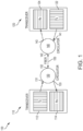
- Fig 1 illustrates a bi-directional communication system 100 implemented with optical circulators.
- the Bi-directional communication system 100 includes a first transceiver 110, a second transceiver 120, a first circulator 130, a second circulator 140, and an optical fiber 150.
- the first transceiver 110 includes a first transmitter 112 and a first receiver 114.
- the second transceiver 120 includes a second transmitter 122 and a second receiver 124.
- the first circulator 130 includes a first port 131, a second port 132 and a third port 133.
- Circulator 140 includes a fourth port 141, a fifth port 142 and a sixth port 143.
- the first port 131 is optically coupled to the first transmitter 112, while the third port 133 is optically coupled to the first receiver 114.
- the fourth port 141 is optically coupled to the second transmitter 122, while the sixth port 143 is optically coupled to the second receiver 124.
- the second port 132 and the fifth port 142 are connected by an optical fiber 150.
- the first transmitter 112 transmits an optical signal that enters the first port 131.
- the first circulator 130 directs the optical signal entering the first port 131 to exit the second port 132.
- the optical signal then propagates through the optical fiber 150 and enters the fifth port 142 of the second circulator 140.
- the second circulator 140 directs the optical signal to exit the sixth port 143, where the second receiver 124 receives the signal.
- the second transmitter 122 transmits an optical signal to the fourth port 141 of the second circulator 140.
- the second circulator 140 directs the optical signal entering the fourth port 141 to exit the fifth port 142.
- the optical signal then propagates through the optical fiber 150 and enters the second port 132 of the first circulator 130.
- the first circulator 130 directs the optical signal to exit the third port 133, where the first receiver 114 receives the signal.
- attaching the circulators at each end of the fiber eliminates the need to use two fibers to connect the transmitters and receivers of the two transmitters.
- optical circulators can improve the efficiency of networks employing optical circuit switching technologies.
- CMOS complementary metal-oxide-semiconductor
- Integrated components have great potential to reduce the cost and size of fiber optic networks.
- many critical devices utilized in silicon photonics such as waveguide based devices, are sensitive to polarization states. This means that the characteristics of the device vary based on the polarization of the light being used within the device.
- many types of Mach-Zehnder based Rx demultiplexer (demux) devices are polarization sensitive because the effective index of the waveguide is dependent on the polarization. Consequently, the integrated devices work more efficiently when receiving optical signals propagating in one polarized state than when they receive optical signals in another polarized state.
- devices work more efficiently when receiving optical signals propagating in a p-polarized state as opposed to s-polarized signals.
- silicon photonic IC transmitters can be configured to transmit an optical signal in a specific polarized state, the optical signal typically does not reach a corresponding receiver in the same polarized state. This is because the optical signal can become depolarized as it propagates through a fiber due to the inherent properties of the fiber.
- Certain grating couplers have been shown to separate orthogonal polarization modes. However, many grating couplers have a high fundamental optical loss.
- the use of an external circulator can be undesirable due to added size, cost and optical loss associated with the circulator. Therefore, it may be preferable to construct an integrated device that allows the combination of bi-directional links with silicon photonic technologies for lower cost, high density optical interconnects.
- This disclosure proposes an integrated circulator configured to split the polarized states of an input signal into two component signals, and transmit the component signals to separate ports with their polarization states substantially aligned.
- Devices according to this disclosure can address the issues associated with enabling bi-directional communications between photonic IC-based transceivers primarily in several ways.
- the subject device in terms of size, is designed small enough such that it can be integrated with the photonic IC-based transceiver.
- the subject device's polarization splitting/combining components are configured in such a manner as to split the mixed polarization optical signal input into two separate optical signal components with orthogonal polarizations, and further rotating these separate optical signals to produce an output that accommodates the signal polarization requirements of the silicon photonics IC.
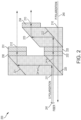
- FIG. 2 shows a schematic of an example of an integrated optical circulator 200, according to an illustrative implementation.
- the integrated optical circulator 200 can be used to implement bi-directional, polarization diverse optical links using silicon photonics.
- the integrated optical circulator 200 includes a first port 210, a second port 211, a third port 212, and a fourth port 213.
- the integrated optical circulator also includes a first polarizing beam splitter 220, a first reflective surface 221, a second polarizing beam splitter 222 and a second reflective surface 223.
- the first polarizing beam splitter 220 and the second polarizing beam splitter 222 may be polarizing beam splitters known in the art, such as polarizing cube beam splitters composed of a birefringent medium.
- the first reflective surface 221 or the second reflective surface 223 are polarizing beam splitters. In other embodiments, both are polarization beam splitters.
- the integrated optical circulator also includes a first optical polarization rotator 230, a second optical polarization rotator 231, a third optical polarization rotator 232, a fourth optical polarization rotator 233 and a fifth optical polarization rotator 234.
- the optical circulator 200 is a free space optical component.
- the second port 211 is positioned to receive a second optical signal 241.
- the second optical signal 241 includes a first optical signal component 241a and a second optical signal component 241b.
- the first polarization beam splitter 220 is optically coupled with the second port 211 and positioned to receive the second optical signal 241 after the second optical signal 241 propagates through the second port 211.
- the third optical polarization rotator 232 is optically coupled with the first polarizing beam splitter 220 and positioned to receive the second optical signal component 241b after it transmits through the first polarizing beam splitter 220.
- the fourth optical polarization rotator 233 is optically coupled with the third optical polarization rotator 232 and positioned to receive the second optical signal component 241b after it propagates through the third optical polarization rotator 232.
- the second polarizing beam splitter 222 is optically coupled with the fourth optical polarization rotator 233 and positioned to receive the second optical signal component 241b after it propagates through the fourth optical polarization rotator 233.
- the second reflective surface 223 is optically coupled to the second polarizing beam splitter 222 and positioned to receive the second optical signal component 241b after it is reflected by the second polarizing beam splitter 222.
- the fifth optical polarization rotator 234 is optically coupled with the second reflective surface 223 and positioned to receive the second optical signal component 241b after it propagates through the fifth optical polarization rotator 234.
- the first port 240 is optically coupled with the second polarizing beam splitter 222 and positioned to receive a first optical signal 240.
- the first reflective surface 221 is optically coupled with the first polarizing beam splitter 220 and positioned to receive the first optical signal component 221a after it is reflected by the first polarizing beam splitter 220.
- the first optical polarization rotator 230 is optically coupled with the first reflective surface 221 and positioned to receive the first optical signal component 241a after it is reflected by the first reflective surface 221.
- the second optical polarization rotator 231 is optically coupled with the first optical polarization rotator 230 and positioned to receive the first optical signal component 241a after it propagates through the first optical polarization rotator 230.
- the third port 212 is optically coupled with the second polarization rotator 231 and positioned to receive the first optical signal component 241a after it propagates through the second optical polarization rotator 231.
- the first port 210 can receive the first optical signal 240 from a transmitter for coupling into the bi-directional optical link.
- the second port 211 can couple to a bi-directional optical link.
- the second port 211 can transmit the first optical signal 240 to the bi-directional optical link to which the second port 211 is coupled.
- the second port 211 can also receive the second optical signal 241 from the bi-directional optical link.
- the first polarizing beam splitter 220 can be configured to receive the second optical signal 241.
- the first polarizing beam splitter 220 can also be configured to split the second optical signal 241 into the first optical signal component 241a and the second optical signal component 241b.
- the second optical signal 241 has a mixed polarization when it is initially received at the second port 211 as denoted by the solid line and the dashed line.
- the polarizing beam splitter 220 splits the second optical signal 241, it splits the signal into separate optical signal components with differing linear polarization. Ideally these separate optical signals are fully polarized after the split, with orthogonal polarizations.
- the first polarizing beam splitter 220 can be further configured to direct the first optical signal component 241a towards the first reflective surface 221.
- the first reflective surface 221 can be configured to further direct the first optical signal component 241a to pass through a first optical polarization rotator 230 and a second optical polarization rotator 231.
- the first optical polarization rotator 230 can be a half-wave plate and the second optical polarization rotator 231 can be a Faraday rotator.
- the third port can be configured to transmit the first optical signal component 241a from the integrated optical circulator 200 after it passes through the second optical polarization rotator 231.
- the first optical signal component 241a when transmitted from the third port 212, can have a first polarization state.
- the first polarizing beam splitter 220 can also be configured to direct the second optical signal component 241b through the third optical polarization rotator 232 and the fourth optical polarization rotator 233.
- the third optical polarization rotator 232 can be a half-wave plate and the fourth optical polarization rotator 233 can be a Faraday rotator.
- the second polarizing beam splitter 222 can be coupled to the fourth optical polarization rotator 233 and configured to receive the second optical signal component 241b after the second optical signal component 241b passes through the fourth optical polarization rotator.
- the second polarizing beam splitter 222 can also be configured to direct the second optical signal component 241b towards the second reflective surface 223.
- the second reflective surface 223 can be configured to direct the second optical signal component 241b towards the fifth optical polarization rotator 234.
- the fourth port 213 can be configured to transmit the second optical signal component 241b after it passes through the fifth optical polarization rotator 234.
- the fourth port 213 can be coupled to a second receiver port and be configured to transmit the received second optical signal component 241b into the second receiver port.
- the second optical signal component 241b, when transmitted from the fourth port 213 can have a second polarization state substantially aligned with the first polarization state.
- the second optical polarization rotator 231 and the fourth optical polarization rotator 233 which in this example are Faraday rotators, are optional and provide additional performance benefits if the corresponding receiver ports create high optical reflection.
- the circulator can reduce signal loss.
- the first optical signal 240 is p-polarized when it is received by the first port 210. This is because most semiconductor lasers are p-polarized. Consequently, the first optical signal 240 is fully polarized and can propagate through the various polarizing beam splitters and rotators to be received by the second port.
- Another advantage of the present circulator is that it eliminates the need for an optical isolator.
- Most transceivers today utilize optical isolators, which are placed in front of or downstream from the transmitter in order to redirect reflection signals external to the transceiver away from the transmitted laser. This is because unwanted incoming external optical reflection signals can affect laser operation and stability.
- the silicon photonic chip's transmitter port Tx is isolated from optical signals, and thus there is no need for an optical isolator. Elimination of the isolator reduces optical loss and cost, and improves transceiver density.
- Fig 3 shows a schematic of an additional example of an integrated optical circulator 300 according to an illustrative implementation.
- the integrated optical circulator 300 can be used to implement bi-directional, polarization diverse optical links using silicon photonics.
- the integrated optical circulator 300 is similar to the integrated optical circulator 200 except that optical polarization rotators 230 and 232 are one contiguous optical polarization rotator, and optical polarization rotators 231 and 233 are also one contiguous optical polarization rotator.
- the integrated optical circulator 300 includes a first port 310, a second port 311, a third port 312, and a fourth port 313.
- the integrated optical circulator also includes a first polarizing beam splitter 320, a first reflective surface 321,a second polarizing beam splitter 322 and a second reflective surface 323.
- the integrated optical circulator also includes a first optical polarization rotator 330, a second optical polarization rotator 331, and a third optical polarization rotator 332.
- the first port 310 can receive a first optical signal 340 from a transmitter for coupling into the bi-directional optical link.
- the second port 311 can couple to a bi-directional optical link.
- the second port 311 can transmit the first optical signal 340 to the bi-directional optical link to which the first port 311 is coupled.
- the second port 311 can also receive a second optical signal 341 from the bi-directional optical link.
- the first polarizing beam splitter 320 can be optically coupled to the second port 311.
- the first polarizing beam splitter 320 can be configured to receive the second optical signal 341.
- the first polarizing beam splitter 320 can also be configured to split the second optical signal 341 into a first optical signal component 341a and a second optical signal component 341b.
- the first polarizing beam splitter 320 can be further configured to direct the first optical signal component 341a towards the first reflective surface 321, wherein the first reflective surface 321 is configured to further direct the first optical signal component 341a to pass through the first optical polarization rotator 330 and the second optical polarization rotator 331.
- the first optical polarization rotator 330 is a half-wave plate and the second optical polarization rotator 331 is a Faraday rotator.
- the third port 312 can be configured to transmit the first optical signal component 341a after it passed through the second optical polarization rotator 331.
- the third port can also be coupled to a first receiver port and be configured to transmit the received first optical signal component 341a into the first receiver port.
- the first optical signal component 341a when transmitted from the third port 312, can have a first polarization state.
- the first polarizing beam splitter 320 can further be configured to direct the second optical signal component 341b through the first optical polarization rotator 330 and the second optical polarization rotator 331.
- the second polarizing beam splitter 322 can be configured to receive the second optical signal component 341b after the second optical signal component 341b passes through the second optical polarization rotator 331.
- the second polarizing beam splitter 322 can also be configured to direct the second optical signal component 341b towards the second reflective surface 323.
- the second reflective surface 323 can be configured to direct the second optical signal component 341b towards the third optical polarization rotator 331.
- the fourth port 313 can be configured to transmit the second optical signal component 341b after it passes through the third optical polarization rotator 332.
- the fourth port 313 can also be coupled to a second receiver port and be configured to transmit the received second optical signal component 341b into the second receiver port.
- the second optical signal component 341b when transmitted from the fourth port 313 can have a second polarization state substantially aligned with the first polarization state.
- the second optical polarization rotator 331 which in this example is a Faraday rotator, is optional and provides additional performance benefits if the corresponding Rx1 and Rx2 ports create high optical reflection.
- integrated optical circulator 300 is similar to integrated optical circulator 200 except that optical polarization rotator 230 and optical polarization rotator 232 are now one continuous optical polarization rotator 330. Additionally, optical polarization rotator 231 and optical polarization rotator 233 are now one continuous optical polarization rotator 331. This design allows for efficient manufacturing of the integrated optical circulator as all the components can now be easily stacked and divided into multiple integrated optical circulators.
- the integrated optical circulator can be used in multi-channel devices, where multiple transmitters and receivers are integrated on a single silicon photonic chip.
- the integrated optical circulator is a free space optical component, vertical displacement of the incoming and outgoing optical signals allow for the reuse and replication of the circulator's components and their function for multiple channels.
- a single integrated optical circulator can be used for two or more transmitter/receiver ports of a silicon photonic chip.
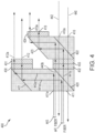
- Fig 4 shows a schematic of an additional example of an integrated optical circulator 400 according to an illustrative implementation.
- the integrated optical circulator 400 can be used to implement bi-directional, polarization diverse optical links using silicon photonics with multiple transceivers.
- the integrated optical circulator 400 is similar to the integrated optical circulator 200 except that integrated optical circulator 400 is configured to receive and separate additional optical signals.
- the integrated optical circulator 400 includes a first port 410, a second port 411, a third port 412, a fourth port 413, a fifth port 410a, a sixth port 411a, a seventh port 412a and an eighth port 413a.
- the integrated optical circulator also includes a first polarizing beam splitter 420, a first reflective surface 421,a second polarizing beam splitter 422 and a second reflective surface 423.
- the integrated optical circulator also includes a first optical polarization rotator 430, a second optical polarization rotator 431, a third optical polarization rotator 432, a fourth optical polarization rotator 433 and a fifth optical polarization rotator 434.
- the first port 410 and the fifth port 410a can receive a first optical signal 440 and a third optical signal 442 respectively, wherein both optical signals are received from transmitters for coupling into the bi-directional optical link.
- the second port 411 and the sixth port 411a can couple to bi-directional optical links.
- the second port 411 and the sixth port 411a can transmit the first optical signal 440 and the third optical signal 442 respectively.
- the second port 411 and the sixth port 411a can transmit the received optical signals to the bi-directional optical links to which they are coupled.
- the second port 411 and the sixth port 411a can also receive a second optical signal 441 and a fourth optical signal 443 from the bi-directional optical links to which they are coupled.
- the first polarizing beam splitter 420 can be optically coupled to the second port 411 and the sixth port 411a.
- the first polarizing beam splitter 420 can be configured to receive the second optical signal 441 and the fourth optical signal 443.
- the first polarizing beam splitter 420 can also be configured to split the second optical signal 441 into a first optical signal component 441a and a second optical signal component 441b.
- the first polarizing beam splitter 420 can further be configured to split the fourth optical signal 443 into a third optical signal component 443a and a fourth optical signal component 443b.
- the first polarizing beam splitter 420 can be further configured to direct the first optical signal component 441a and the third optical signal component 443a towards the first reflective surface 421, wherein the first reflective surface 421 is configured to further direct the first optical signal component 441a and the third optical signal component 443a to pass through a first optical polarization rotator 430 and a second optical polarization rotator 431.
- the first optical polarization rotator 431 is a half-wave plate and the second optical polarization rotator 431 is a Faraday rotator.
- the third port 412 and the seventh port 412a can be configured to transmit the first optical signal component 441a and the third optical signal component 443a respectively after they pass through the second optical polarization rotator 431.
- the third port 412 and the seventh port 412a can also be coupled to a first receiver port and a second receiver port respectively.
- the third port 412 can be configured to transmit the first optical signal component 441a into the first receiver port.
- the seventh port 412a can be configured to transmit the third optical signal 443a into the second receiver port.
- the first optical signal component 441a and the third optical signal component 443a when transmitted from the third port 412 and the seventh port 412a respectively, can have a first polarization state.
- the first polarizing beam splitter 420 can also further be configured to direct the second optical signal component 441b and the fourth optical signal component 443b through the third optical polarization rotator 432 and the fourth optical polarization rotator 433.
- the third optical polarization rotator 432 is a half-wave plate and the fourth optical polarization rotator 433 is a Faraday rotator.
- the second polarizing beam splitter 422 can be configured to receive the second optical signal component 241b and the fourth optical signal component 443b after they pass through the fourth optical polarization rotator 433.
- the second polarizing beam splitter 422 can be configured to direct the second optical signal component 441b and the fourth optical signal component 443b towards the second reflective surface 423.
- the second reflective surface 423 can be configured to direct the second optical signal component 441b and the fourth optical signal component 443b towards the fifth optical polarization rotator 434.
- the fourth port 413 can be configured to transmit the second optical signal component 441b after it passes through the fifth optical polarization rotator 434.
- the fourth port 413 can also be coupled to a third receiver port and be configured to transmit the second optical signal component 441b into the third receiver port.
- the eighth port 413a can configured to transmit the fourth optical signal component 443b after it passes through the fifth optical polarization rotator 434.
- the eighth port 413a can also be coupled to a fourth receiver port and be configured to transmit the received fourth optical signal component 443b into the fourth receiver port.
- the second optical signal component 441b and the fourth optical signal component 443b when transmitted from the fourth port 413 and the eighth port 413a respectively, can have a second polarization state substantially aligned with the first polarization state.
- references to "or” may be construed as inclusive so that any terms described using “or” may indicate any of a single, more than one, and all of the described terms.
- the labels “first,” “second,” “third,” and so forth are not necessarily meant to indicate an ordering and are generally used merely to distinguish between like or similar items or elements.
Landscapes
- Physics & Mathematics (AREA)
- General Physics & Mathematics (AREA)
- Optics & Photonics (AREA)
- Nonlinear Science (AREA)
- Engineering & Computer Science (AREA)
- Power Engineering (AREA)
- Microelectronics & Electronic Packaging (AREA)
- Optical Communication System (AREA)
Abstract
Description
- This application claims the benefit of, and priority to,
U.S. Patent Application No. 15/975,268, filed May 9, 2018 U.S. Provisional Application No. 62/595,539, titled "Integrated Optical Circulator Enabling Polarization Diversity", and filed on December 6, 2017 - Today's optical communication networks require the management of a large number of optical fiber interconnections. In many of these interconnections, the transmitted and received signals are run in two separate fibers. Bi-directional communication, where the upstream and downstream signals are running inside a single fiber, is an effective way to reduce the number of fibers used in a fiber-optic communication network. The key for implementing such bi-directional communications is to effectively separate and combine the upstream and downstream signals. One approach to separating and combining upstream and downstream signals is to add optical circulators to each end of a fiber.
- At least one aspect is directed to an integrated optical circulator enabling polarization diversity. The integrated optical circulator includes a first port configured to receive a first optical signal. The integrated optical circulator includes a second port configured to transmit the first optical signal received at the first port and also configured to receive a second optical signal. The integrated optical circulator includes a first polarizing beam splitter configured to receive the second optical signal, split the second optical signal into a first optical signal component and a second optical signal component, direct the first optical signal component towards a first reflective surface wherein the first reflective surface is configured to further direct the first optical signal component to pass through a first optical polarization rotator, and direct the second optical signal component through a second optical polarization rotator. The integrated optical circulator includes a second polarizing beam splitter configured to receive the second optical signal component after the second optical signal component passes through the second optical polarization rotator, and direct the second optical signal component towards a second reflective surface. The second reflective surface directs the second optical signal component towards a third optical polarization rotator. The integrated optical circulator includes a third configured to transmit the first optical signal component of the second optical signal after it passes through the first optical polarization rotator, the third port transmitting the first component at a first polarization state. The integrated optical circulator includes a fourth port configured to receive the second component of the second optical signal after it passes through the third optical polarization rotator, the fourth port transmitting the second optical signal component at a second polarization state substantially aligned with the first polarization state.
- These and other aspects and implementations are discussed in detail below. The foregoing information and the following detailed description include illustrative examples of various aspects and implementations, and provide an overview or framework for understanding the nature and character of the claimed aspects and implementations. The drawings provide illustration and a further understanding of the various aspects and implementations, and are incorporated in and constitute a part of this specification.
- The accompanying drawings are not intended to be drawn to scale. Like reference numbers and designations in the various drawings indicate like elements. For purposes of clarity, not every component may be labeled in every drawing. In the drawings:
-
Figure 1 shows a schematic of an example of a bi-directional communication system implemented with circulators, according to an illustrative implementation; -
Figure 2 shows a schematic of an example of an integrated optical circulator, according to an illustrative implementation; -
Figure 3 shows a schematic of a further example of an integrated optical circulator, according to an illustrative implementation and -
Figure 4 shows a schematic of a further example of an integrated optical circulator configured for use with multiple transceivers, according to an illustrative implementation. - The various concepts introduced above and discussed in greater detail below may be implemented in any of numerous ways, as the described concepts are not limited to any particular manner of implementation. Examples of specific implementations and applications are provided primarily for illustrative purposes.
- Today's optical communication networks require the management of a large number of optical fiber interconnections. In many of these interconnections, the transmitted and received signals are run in two separate fibers. Employing bi-directional communication, where the transmitted and received signals are running inside a single fiber, can reduce the number of fibers used in a fiber-optic communication network. The key for implementing such bi-directional communications is to effectively separate and combine the upstream and downstream signals at each end of the fibers.
- One approach to establishing bi-directional communications is to add optical circulators to each end of a fiber. Optical circulators are typically three port devices which have a cyclic connectivity. For instance, an input optical signal enters port 1 of the circulator and is directed to port 2, while another input optical signal enters port 2 and is directed to port 3. To achieve this functionality, the circulator is equipped with a combination of polarizers, non-reciprocal/magneto-optical materials such as Garnet, and phase retarders.
-
Fig 1 illustrates abi-directional communication system 100 implemented with optical circulators. The Bi-directionalcommunication system 100 includes afirst transceiver 110, asecond transceiver 120, afirst circulator 130, asecond circulator 140, and anoptical fiber 150. Thefirst transceiver 110 includes afirst transmitter 112 and afirst receiver 114. Similarly, thesecond transceiver 120 includes asecond transmitter 122 and asecond receiver 124. Thefirst circulator 130 includes afirst port 131, asecond port 132 and athird port 133. Circulator 140 includes afourth port 141, afifth port 142 and asixth port 143. Thefirst port 131 is optically coupled to thefirst transmitter 112, while thethird port 133 is optically coupled to thefirst receiver 114. Similarly, thefourth port 141 is optically coupled to thesecond transmitter 122, while thesixth port 143 is optically coupled to thesecond receiver 124. Thesecond port 132 and thefifth port 142 are connected by anoptical fiber 150. - The
first transmitter 112 transmits an optical signal that enters thefirst port 131. Thefirst circulator 130 directs the optical signal entering thefirst port 131 to exit thesecond port 132. The optical signal then propagates through theoptical fiber 150 and enters thefifth port 142 of thesecond circulator 140. Once the optical signal enters thefifth port 142, thesecond circulator 140 directs the optical signal to exit thesixth port 143, where thesecond receiver 124 receives the signal. Similarly, thesecond transmitter 122 transmits an optical signal to thefourth port 141 of thesecond circulator 140. Thesecond circulator 140 directs the optical signal entering thefourth port 141 to exit thefifth port 142. The optical signal then propagates through theoptical fiber 150 and enters thesecond port 132 of thefirst circulator 130. Once the optical signal enters thesecond port 132, thefirst circulator 130 directs the optical signal to exit thethird port 133, where thefirst receiver 114 receives the signal. As shown in this example, attaching the circulators at each end of the fiber eliminates the need to use two fibers to connect the transmitters and receivers of the two transmitters. In addition to reducing the number of optical fibers needed for optical communication networks, optical circulators can improve the efficiency of networks employing optical circuit switching technologies. - One disadvantage of adding traditional circulators to a fiber optic network is that realization of their advantages requires adding circulators external to the optical transceivers, which can increase cost, size, and insertion loss of the fiber optic link. However, integrated silicon photonics is a developing technology in the field of optical communications which promises low power and low cost photonic integrated circuits by leveraging low cost, high yielding silicon complementary metal-oxide-semiconductor (CMOS) integrated circuit foundries to fabricate integrated photonics in silicon, where the various transmitter and receiver devices of the transceiver would be combined in a single chip. These photonic integrated circuits form the engine of the optical transceiver. Thus, it may be preferable to configure a circulator so that it can be integrated with the photonic integrated circuit in order to eliminate the need to add circulators external to the optical transceiver.
- Integrated components have great potential to reduce the cost and size of fiber optic networks. However, many critical devices utilized in silicon photonics, such as waveguide based devices, are sensitive to polarization states. This means that the characteristics of the device vary based on the polarization of the light being used within the device. For example, many types of Mach-Zehnder based Rx demultiplexer (demux) devices are polarization sensitive because the effective index of the waveguide is dependent on the polarization. Consequently, the integrated devices work more efficiently when receiving optical signals propagating in one polarized state than when they receive optical signals in another polarized state. In the case of silicon photonics, devices work more efficiently when receiving optical signals propagating in a p-polarized state as opposed to s-polarized signals. Thus, it is difficult to design integrated devices to be polarization diverse in most standard CMOS processes. Although silicon photonic IC transmitters can be configured to transmit an optical signal in a specific polarized state, the optical signal typically does not reach a corresponding receiver in the same polarized state. This is because the optical signal can become depolarized as it propagates through a fiber due to the inherent properties of the fiber.
- Traditional circulators utilize birefringent materials to separate the orthogonal polarizations of an incoming optical signal. However, as the optical signal propagates through the circulator, the orthogonal polarizations are recombined by further birefringent materials. Thus, the optical signal carries mixed polarizations as it exits the circulator and is received by the transceiver. But, as discussed above, the integrated silicon devices may not work efficiently with the s-polarized component of the optical signal, and an unfavorable amount of optical signal loss will occur. Consequently, it is unfavorable to integrate traditional circulators with silicon photonic ICs. Accordingly, it is advantageous to design a device that would enable bi-directional communications between photonics IC-based transceivers, while addressing the polarization sensitivity of the silicon based devices.
- One way for achieving bi-directional communication with silicon photonic integrated devices, while addressing the polarization sensitivity of the silicon based devices, is to use a traditional external circulator with an integrated grating coupler in the silicon photonic IC. Certain grating couplers have been shown to separate orthogonal polarization modes. However, many grating couplers have a high fundamental optical loss. Also, as discussed earlier, the use of an external circulator can be undesirable due to added size, cost and optical loss associated with the circulator. Therefore, it may be preferable to construct an integrated device that allows the combination of bi-directional links with silicon photonic technologies for lower cost, high density optical interconnects. This disclosure proposes an integrated circulator configured to split the polarized states of an input signal into two component signals, and transmit the component signals to separate ports with their polarization states substantially aligned.
- Devices according to this disclosure can address the issues associated with enabling bi-directional communications between photonic IC-based transceivers primarily in several ways. For example, in terms of size, the subject device is designed small enough such that it can be integrated with the photonic IC-based transceiver. Additionally, in order to reduce optical loss, the subject device's polarization splitting/combining components are configured in such a manner as to split the mixed polarization optical signal input into two separate optical signal components with orthogonal polarizations, and further rotating these separate optical signals to produce an output that accommodates the signal polarization requirements of the silicon photonics IC. To be sure, by separating the mixed polarization optical signal input into two signal components, and providing the signal components to an integrated transceiver in substantially the same polarization state, signal loss is reduced and both signal components are provided to the photonic chip in a polarized state that allow for effective demultiplexing and other functions being implemented in the chip.
-
Figure 2 shows a schematic of an example of an integratedoptical circulator 200, according to an illustrative implementation. The integratedoptical circulator 200 can be used to implement bi-directional, polarization diverse optical links using silicon photonics. The integratedoptical circulator 200 includes afirst port 210, asecond port 211, athird port 212, and afourth port 213. The integrated optical circulator also includes a firstpolarizing beam splitter 220, a firstreflective surface 221, a secondpolarizing beam splitter 222 and a secondreflective surface 223. The firstpolarizing beam splitter 220 and the secondpolarizing beam splitter 222 may be polarizing beam splitters known in the art, such as polarizing cube beam splitters composed of a birefringent medium. In some embodiments, the firstreflective surface 221 or the secondreflective surface 223 are polarizing beam splitters. In other embodiments, both are polarization beam splitters. The integrated optical circulator also includes a firstoptical polarization rotator 230, a secondoptical polarization rotator 231, a thirdoptical polarization rotator 232, a fourthoptical polarization rotator 233 and a fifthoptical polarization rotator 234. - The
optical circulator 200 is a free space optical component. Thesecond port 211 is positioned to receive a secondoptical signal 241. In some implementations, the secondoptical signal 241 includes a firstoptical signal component 241a and a secondoptical signal component 241b. The firstpolarization beam splitter 220 is optically coupled with thesecond port 211 and positioned to receive the secondoptical signal 241 after the secondoptical signal 241 propagates through thesecond port 211. The thirdoptical polarization rotator 232 is optically coupled with the firstpolarizing beam splitter 220 and positioned to receive the secondoptical signal component 241b after it transmits through the firstpolarizing beam splitter 220. The fourthoptical polarization rotator 233 is optically coupled with the thirdoptical polarization rotator 232 and positioned to receive the secondoptical signal component 241b after it propagates through the thirdoptical polarization rotator 232. The secondpolarizing beam splitter 222 is optically coupled with the fourthoptical polarization rotator 233 and positioned to receive the secondoptical signal component 241b after it propagates through the fourthoptical polarization rotator 233. The secondreflective surface 223 is optically coupled to the secondpolarizing beam splitter 222 and positioned to receive the secondoptical signal component 241b after it is reflected by the secondpolarizing beam splitter 222. The fifthoptical polarization rotator 234 is optically coupled with the secondreflective surface 223 and positioned to receive the secondoptical signal component 241b after it propagates through the fifthoptical polarization rotator 234. Thefirst port 240 is optically coupled with the secondpolarizing beam splitter 222 and positioned to receive a firstoptical signal 240. The firstreflective surface 221 is optically coupled with the firstpolarizing beam splitter 220 and positioned to receive the first optical signal component 221a after it is reflected by the firstpolarizing beam splitter 220. The firstoptical polarization rotator 230 is optically coupled with the firstreflective surface 221 and positioned to receive the firstoptical signal component 241a after it is reflected by the firstreflective surface 221. The secondoptical polarization rotator 231 is optically coupled with the firstoptical polarization rotator 230 and positioned to receive the firstoptical signal component 241a after it propagates through the firstoptical polarization rotator 230. Thethird port 212 is optically coupled with thesecond polarization rotator 231 and positioned to receive the firstoptical signal component 241a after it propagates through the secondoptical polarization rotator 231. - The
first port 210 can receive the firstoptical signal 240 from a transmitter for coupling into the bi-directional optical link. Thesecond port 211 can couple to a bi-directional optical link. Thesecond port 211 can transmit the firstoptical signal 240 to the bi-directional optical link to which thesecond port 211 is coupled. Thesecond port 211 can also receive the secondoptical signal 241 from the bi-directional optical link. The firstpolarizing beam splitter 220 can be configured to receive the secondoptical signal 241. The firstpolarizing beam splitter 220 can also be configured to split the secondoptical signal 241 into the firstoptical signal component 241a and the secondoptical signal component 241b. The secondoptical signal 241 has a mixed polarization when it is initially received at thesecond port 211 as denoted by the solid line and the dashed line. When thepolarizing beam splitter 220 splits the secondoptical signal 241, it splits the signal into separate optical signal components with differing linear polarization. Ideally these separate optical signals are fully polarized after the split, with orthogonal polarizations. - The first
polarizing beam splitter 220 can be further configured to direct the firstoptical signal component 241a towards the firstreflective surface 221. The firstreflective surface 221 can be configured to further direct the firstoptical signal component 241a to pass through a firstoptical polarization rotator 230 and a secondoptical polarization rotator 231. In some implementations, the firstoptical polarization rotator 230 can be a half-wave plate and the secondoptical polarization rotator 231 can be a Faraday rotator. The third port can be configured to transmit the firstoptical signal component 241a from the integratedoptical circulator 200 after it passes through the secondoptical polarization rotator 231. The firstoptical signal component 241a, when transmitted from thethird port 212, can have a first polarization state. - The first
polarizing beam splitter 220 can also be configured to direct the secondoptical signal component 241b through the thirdoptical polarization rotator 232 and the fourthoptical polarization rotator 233. In some implementations, the thirdoptical polarization rotator 232 can be a half-wave plate and the fourthoptical polarization rotator 233 can be a Faraday rotator. The secondpolarizing beam splitter 222 can be coupled to the fourthoptical polarization rotator 233 and configured to receive the secondoptical signal component 241b after the secondoptical signal component 241b passes through the fourth optical polarization rotator. The secondpolarizing beam splitter 222 can also be configured to direct the secondoptical signal component 241b towards the secondreflective surface 223. The secondreflective surface 223 can be configured to direct the secondoptical signal component 241b towards the fifthoptical polarization rotator 234. Thefourth port 213 can be configured to transmit the secondoptical signal component 241b after it passes through the fifthoptical polarization rotator 234. Thefourth port 213 can be coupled to a second receiver port and be configured to transmit the received secondoptical signal component 241b into the second receiver port. The secondoptical signal component 241b, when transmitted from thefourth port 213 can have a second polarization state substantially aligned with the first polarization state. Note that the secondoptical polarization rotator 231 and the fourthoptical polarization rotator 233, which in this example are Faraday rotators, are optional and provide additional performance benefits if the corresponding receiver ports create high optical reflection. By ensuring both optical signal components are substantially aligned when they are transmitted at thethird port 212 and thefourth port 213, the circulator can reduce signal loss. - The first
optical signal 240 is p-polarized when it is received by thefirst port 210. This is because most semiconductor lasers are p-polarized. Consequently, the firstoptical signal 240 is fully polarized and can propagate through the various polarizing beam splitters and rotators to be received by the second port. - Another advantage of the present circulator is that it eliminates the need for an optical isolator. Most transceivers today utilize optical isolators, which are placed in front of or downstream from the transmitter in order to redirect reflection signals external to the transceiver away from the transmitted laser. This is because unwanted incoming external optical reflection signals can affect laser operation and stability. However, with the use of the present circulator, the silicon photonic chip's transmitter port Tx is isolated from optical signals, and thus there is no need for an optical isolator. Elimination of the isolator reduces optical loss and cost, and improves transceiver density.
- The specific placements of the various circulator components are not limited to only the configuration shown in
Fig 2 . For instance,Fig 3 shows a schematic of an additional example of an integratedoptical circulator 300 according to an illustrative implementation. The integratedoptical circulator 300 can be used to implement bi-directional, polarization diverse optical links using silicon photonics. The integratedoptical circulator 300 is similar to the integratedoptical circulator 200 except thatoptical polarization rotators optical polarization rotators optical circulator 300 includes afirst port 310, asecond port 311, athird port 312, and afourth port 313. The integrated optical circulator also includes a firstpolarizing beam splitter 320, a firstreflective surface 321,a secondpolarizing beam splitter 322 and a secondreflective surface 323. The integrated optical circulator also includes a firstoptical polarization rotator 330, a secondoptical polarization rotator 331, and a thirdoptical polarization rotator 332. - The
first port 310 can receive a firstoptical signal 340 from a transmitter for coupling into the bi-directional optical link. Thesecond port 311 can couple to a bi-directional optical link. Thesecond port 311 can transmit the firstoptical signal 340 to the bi-directional optical link to which thefirst port 311 is coupled. Thesecond port 311 can also receive a secondoptical signal 341 from the bi-directional optical link. The firstpolarizing beam splitter 320 can be optically coupled to thesecond port 311. The firstpolarizing beam splitter 320 can be configured to receive the secondoptical signal 341. The firstpolarizing beam splitter 320 can also be configured to split the secondoptical signal 341 into a first optical signal component 341a and a secondoptical signal component 341b. - The first
polarizing beam splitter 320 can be further configured to direct the first optical signal component 341a towards the firstreflective surface 321, wherein the firstreflective surface 321 is configured to further direct the first optical signal component 341a to pass through the firstoptical polarization rotator 330 and the secondoptical polarization rotator 331. In this example, the firstoptical polarization rotator 330 is a half-wave plate and the secondoptical polarization rotator 331 is a Faraday rotator. Thethird port 312 can be configured to transmit the first optical signal component 341a after it passed through the secondoptical polarization rotator 331. The third port can also be coupled to a first receiver port and be configured to transmit the received first optical signal component 341a into the first receiver port. The first optical signal component 341a, when transmitted from thethird port 312, can have a first polarization state. - The first
polarizing beam splitter 320 can further be configured to direct the secondoptical signal component 341b through the firstoptical polarization rotator 330 and the secondoptical polarization rotator 331. The secondpolarizing beam splitter 322 can be configured to receive the secondoptical signal component 341b after the secondoptical signal component 341b passes through the secondoptical polarization rotator 331. The secondpolarizing beam splitter 322 can also be configured to direct the secondoptical signal component 341b towards the secondreflective surface 323. The secondreflective surface 323 can be configured to direct the secondoptical signal component 341b towards the thirdoptical polarization rotator 331. Thefourth port 313 can be configured to transmit the secondoptical signal component 341b after it passes through the thirdoptical polarization rotator 332. Thefourth port 313 can also be coupled to a second receiver port and be configured to transmit the received secondoptical signal component 341b into the second receiver port. The secondoptical signal component 341b, when transmitted from thefourth port 313 can have a second polarization state substantially aligned with the first polarization state. Note that the secondoptical polarization rotator 331, which in this example is a Faraday rotator, is optional and provides additional performance benefits if the corresponding Rx1 and Rx2 ports create high optical reflection. - Notice that integrated
optical circulator 300 is similar to integratedoptical circulator 200 except thatoptical polarization rotator 230 andoptical polarization rotator 232 are now one continuousoptical polarization rotator 330. Additionally,optical polarization rotator 231 andoptical polarization rotator 233 are now one continuousoptical polarization rotator 331. This design allows for efficient manufacturing of the integrated optical circulator as all the components can now be easily stacked and divided into multiple integrated optical circulators. - Furthermore, the integrated optical circulator can be used in multi-channel devices, where multiple transmitters and receivers are integrated on a single silicon photonic chip. As the integrated optical circulator is a free space optical component, vertical displacement of the incoming and outgoing optical signals allow for the reuse and replication of the circulator's components and their function for multiple channels. Thus, a single integrated optical circulator can be used for two or more transmitter/receiver ports of a silicon photonic chip.
- For instance,
Fig 4 shows a schematic of an additional example of an integratedoptical circulator 400 according to an illustrative implementation. The integratedoptical circulator 400 can be used to implement bi-directional, polarization diverse optical links using silicon photonics with multiple transceivers. The integratedoptical circulator 400 is similar to the integratedoptical circulator 200 except that integratedoptical circulator 400 is configured to receive and separate additional optical signals. The integratedoptical circulator 400 includes afirst port 410, asecond port 411, athird port 412, afourth port 413, afifth port 410a, a sixth port 411a, aseventh port 412a and aneighth port 413a. The integrated optical circulator also includes a firstpolarizing beam splitter 420, a firstreflective surface 421,a secondpolarizing beam splitter 422 and a secondreflective surface 423. The integrated optical circulator also includes a firstoptical polarization rotator 430, a secondoptical polarization rotator 431, a thirdoptical polarization rotator 432, a fourthoptical polarization rotator 433 and a fifthoptical polarization rotator 434. - The
first port 410 and thefifth port 410a can receive a firstoptical signal 440 and a thirdoptical signal 442 respectively, wherein both optical signals are received from transmitters for coupling into the bi-directional optical link. Thesecond port 411 and the sixth port 411a can couple to bi-directional optical links. Thesecond port 411 and the sixth port 411a can transmit the firstoptical signal 440 and the thirdoptical signal 442 respectively. Thesecond port 411 and the sixth port 411a can transmit the received optical signals to the bi-directional optical links to which they are coupled. Thesecond port 411 and the sixth port 411a can also receive a secondoptical signal 441 and a fourthoptical signal 443 from the bi-directional optical links to which they are coupled. The firstpolarizing beam splitter 420 can be optically coupled to thesecond port 411 and the sixth port 411a. The firstpolarizing beam splitter 420 can be configured to receive the secondoptical signal 441 and the fourthoptical signal 443. The firstpolarizing beam splitter 420 can also be configured to split the secondoptical signal 441 into a firstoptical signal component 441a and a secondoptical signal component 441b. The firstpolarizing beam splitter 420 can further be configured to split the fourthoptical signal 443 into a thirdoptical signal component 443a and a fourthoptical signal component 443b. - The first
polarizing beam splitter 420 can be further configured to direct the firstoptical signal component 441a and the thirdoptical signal component 443a towards the firstreflective surface 421, wherein the firstreflective surface 421 is configured to further direct the firstoptical signal component 441a and the thirdoptical signal component 443a to pass through a firstoptical polarization rotator 430 and a secondoptical polarization rotator 431. In this example, the firstoptical polarization rotator 431 is a half-wave plate and the secondoptical polarization rotator 431 is a Faraday rotator. Thethird port 412 and theseventh port 412a can be configured to transmit the firstoptical signal component 441a and the thirdoptical signal component 443a respectively after they pass through the secondoptical polarization rotator 431. Thethird port 412 and theseventh port 412a can also be coupled to a first receiver port and a second receiver port respectively. Thethird port 412 can be configured to transmit the firstoptical signal component 441a into the first receiver port. Theseventh port 412a can be configured to transmit the thirdoptical signal 443a into the second receiver port. The firstoptical signal component 441a and the thirdoptical signal component 443a , when transmitted from thethird port 412 and theseventh port 412a respectively, can have a first polarization state. - The first
polarizing beam splitter 420 can also further be configured to direct the secondoptical signal component 441b and the fourthoptical signal component 443b through the thirdoptical polarization rotator 432 and the fourthoptical polarization rotator 433. In this example, the thirdoptical polarization rotator 432 is a half-wave plate and the fourthoptical polarization rotator 433 is a Faraday rotator. The secondpolarizing beam splitter 422 can be configured to receive the secondoptical signal component 241b and the fourthoptical signal component 443b after they pass through the fourthoptical polarization rotator 433. The secondpolarizing beam splitter 422 can be configured to direct the secondoptical signal component 441b and the fourthoptical signal component 443b towards the secondreflective surface 423. The secondreflective surface 423 can be configured to direct the secondoptical signal component 441b and the fourthoptical signal component 443b towards the fifthoptical polarization rotator 434. Thefourth port 413 can be configured to transmit the secondoptical signal component 441b after it passes through the fifthoptical polarization rotator 434. Thefourth port 413 can also be coupled to a third receiver port and be configured to transmit the secondoptical signal component 441b into the third receiver port. Theeighth port 413a can configured to transmit the fourthoptical signal component 443b after it passes through the fifthoptical polarization rotator 434. Theeighth port 413a can also be coupled to a fourth receiver port and be configured to transmit the received fourthoptical signal component 443b into the fourth receiver port. The secondoptical signal component 441b and the fourthoptical signal component 443b, when transmitted from thefourth port 413 and theeighth port 413a respectively, can have a second polarization state substantially aligned with the first polarization state. - While this specification contains many specific implementation details, these should not be construed as limitations on the scope of any inventions or of what may be claimed, but rather as descriptions of features specific to particular implementations of particular inventions. Certain features that are described in this specification in the context of separate implementations can also be implemented in combination in a single implementation. Conversely, various features that are described in the context of a single implementation can also be implemented in multiple implementations separately or in any suitable sub-combination. Moreover, although features may be described above as acting in certain combinations and even initially claimed as such, one or more features from a claimed combination can in some cases be excised from the combination, and the claimed combination may be directed to a sub-combination or variation of a sub-combination.
- Similarly, while operations are depicted in the drawings in a particular order, this should not be understood as requiring that such operations be performed in the particular order shown or in sequential order, or that all illustrated operations be performed, to achieve desirable results. In certain circumstances, multitasking and parallel processing may be advantageous. Moreover, the separation of various system components in the implementations described above should not be understood as requiring such separation in all implementations, and it should be understood that the described program components and systems can generally be integrated together in a single software product or packaged into multiple software products.
- References to "or" may be construed as inclusive so that any terms described using "or" may indicate any of a single, more than one, and all of the described terms. The labels "first," "second," "third," and so forth are not necessarily meant to indicate an ordering and are generally used merely to distinguish between like or similar items or elements.
- Various modifications to the implementations described in this disclosure may be readily apparent to those skilled in the art, and the generic principles defined herein may be applied to other implementations without departing from the spirit or scope of this disclosure. Thus, the claims are not intended to be limited to the implementations shown herein, but are to be accorded the widest scope consistent with this disclosure, the principles and the novel features disclosed herein.
- Further implementations are summarized in the following examples:
- Example 1: An integrated optical circulator enabling polarization diversity, the integrated optical circulator comprising: a first port configured to receive a first optical signal; a second port configured to transmit the first optical signal received at the first port and also configured to receive a second optical signal; a first polarization beam splitter configured to: receive the second optical signal; split the second optical signal into a first optical signal component and a second optical signal component; direct the first optical signal component towards a first reflective surface wherein the first reflective surface is configured to further direct the first optical signal component to pass through a first optical polarization rotator; and direct the second optical signal component through a second optical polarization rotator; a second polarization beam splitter configured to receive the second optical signal component after the second optical signal component passes through the second optical polarization rotator, and direct the second optical signal component towards a second reflective surface, the second reflective surface directing the second optical signal component towards a third optical polarization rotator; a third port configured to transmit the first optical signal component of the second optical signal after it passes through the first optical polarization rotator, the third port transmitting the first optical signal component at a first polarization state; and a fourth port configured to transmit the second optical signal component of the second optical signal after it passes through the third optical polarization rotator, the fourth port transmitting the second optical signal component at a second polarization state substantially aligned with the first polarization state.
- Example 2: The integrated optical circulator of example 1 wherein at least one optical polarization rotator is a half-wave plate.
- Example 3: The integrated optical circulator of example 1, wherein the first optical polarization rotator and the second optical polarization rotator are different portions of a continuous optical polarization rotator.
- Example 4: The integrated optical circulator of example 1, wherein: a fifth port is configured to receive a third optical signal; a sixth port is configured to transmit the third optical signal received at the fifth port and also configured to receive a fourth optical signal; the first polarization beam splitter is further configured to: receive the fourth optical signal; split the fourth optical signal into a third optical signal component and a fourth optical signal component; direct the third optical signal component towards the first reflective surface wherein the first reflective surface is configured to further direct the third optical signal component to pass through the first optical polarization rotator; and direct the fourth optical signal component through the second optical polarization rotator; the third polarization beam splitter is configured to receive the fourth optical signal component after the fourth optical signal component passes through the second optical polarization rotator, and direct the fourth optical signal component towards the second reflective surface, the second reflective surface directing the fourth optical signal component towards a third optical polarization rotator; a seventh port configured to transmit the third optical signal component after it passes through the first optical polarization rotator, the seventh port transmitting the third optical signal component at the first polarization state; and an eighth port configured to transmit the fourth optical signal component after it passes through the third optical polarization rotator, the eighth port transmitting the fourth optical signal component at the second polarization state.
- Example 5: The integrated optical circulator of example 1, wherein at least one additional optical polarization rotator is optically coupled to either the first optical polarization rotator, the second optical polarization rotator, or both.
- Example 6: The integrated optical circulator of example 5, wherein the at least one additional optical polarization rotator is a Faraday rotator.
- Example 7: The integrated optical circulator of example 1, wherein the third reflective surface is a polarizing beam splitter.
- Example 8: The integrated optical circulator of example 1, wherein the fourth reflective surface is a polarizing beam splitter
- Example 9: The integrated optical circulator of example 1, wherein the first polarization state and second polarization state are p-polarizations.
- Example 10: The integrated optical circulator of example 1, wherein the first transmitted signal is p-polarized.
- Example 11: The integrated optical circulator of example 1, wherein the first polarizing beam splitter splits the second optical signal into a first optical signal component and a second optical signal component carrying orthogonal polarizations.
Claims (13)
- An integrated optical circulator (200) enabling polarization diversity, the integrated optical circulator comprising:a first port (210) configured to receive a first optical signal (240);a second port (211) configured to transmit the first optical signal received at the first port and also configured to receive a second optical signal (241);a first polarization beam splitter (220) configured to:receive the second optical signal;split the second optical signal into a first optical signal component (241a) and a second optical signal component (241b);direct the first optical signal component towards a first reflective surface (221), anddirect the second optical signal component through a first optical polarization rotator (230);a second polarization beam splitter (222) configured to receive the second optical signal component (241b) after the second optical signal component passes through the first optical polarization rotator (232), wherein the second polarization beam splitter (222) does not receive the first optical signal component (241a); andcharacterized in that:the integrated optical circulator further comprises a third port (212) configured to transmit the first optical signal component (241a) of the second optical signal after it passes through a second optical polarization rotator (230), the third port transmitting the first optical signal component (241a) at a second polarization state substantially aligned with a first polarization state, and/orthe second polarization beam splitter (222) is further configured to direct the second optical signal (241b) component towards a second reflective surface (223), the second reflective surface directing the second optical signal component towards a second optical polarization rotator (234).
- The integrated optical circulator of claim 1, further comprising a fourth port (213) configured to transmit the second optical signal component (241b) after it passes through the first optical polarization rotator, the fourth port transmitting the second optical signal component at the first polarization state.
- The integrated optical circulator of claim 1, wherein the first reflective surface is configured to further direct the first optical signal component to pass through the first optical polarization rotator.
- The integrated optical circulator of claim 1 wherein the first optical polarization rotator is a half-wave plate.
- The integrated optical circulator of claim 1, wherein the first optical polarization rotator is a continuous optical polarization rotator.
- The integrated optical circulator of claim 1, wherein:a fifth port is configured to receive a third optical signal;a sixth port is configured to transmit the third optical signal received at the fifth port and also configured to receive a fourth optical signal;the first polarization beam splitter is further configured to:receive the fourth optical signal;split the fourth optical signal into a third optical signal component and a fourth optical signal component;direct the third optical signal component towards the first reflective surface, wherein the first reflective surface is configured to further direct the third optical signal component to pass through the first optical polarization rotator; anddirect the fourth optical signal component through the first optical polarization rotator;the second polarization beam splitter is configured to receive the fourth optical signal component after the fourth optical signal component passes through the first optical polarization rotator, and direct the fourth optical signal component towards the second reflective surface, the second reflective surface directing the fourth optical signal component towards the third optical polarization rotator;a seventh port configured to transmit the third optical signal component after it passes through the first optical polarization rotator, the seventh port transmitting the third optical signal component at a first polarization state; andan eighth port configured to transmit the fourth optical signal component after it passes through the third optical polarization rotator, the eighth port transmitting the fourth optical signal component at a second polarization state.
- The integrated optical circulator of claim 1, wherein at least one additional optical polarization rotator is optically coupled to either the first optical polarization rotator, the second optical polarization rotator, or both.
- The integrated optical circulator of claim 7, wherein the at least one additional optical polarization rotator is a Faraday rotator.
- The integrated optical circulator of claim 1, further comprising a third reflective surface, wherein the third reflective surface is a polarizing beam splitter.
- The integrated optical circulator of claim 1, further comprising a fourth reflective surface, wherein the forth reflective surface is a polarizing beam splitter.
- The integrated optical circulator of claim 1, wherein the first polarization state and second polarization state are p-polarizations.
- The integrated optical circulator of claim 1, wherein the first transmitted signal is p-polarized.
- The integrated optical circulator of claim 1, wherein the first polarizing beam splitter splits the second optical signal into the first optical signal component and the second optical signal component carrying orthogonal polarizations.
Applications Claiming Priority (4)
| Application Number | Priority Date | Filing Date | Title |
|---|---|---|---|
| US201762595539P | 2017-12-06 | 2017-12-06 | |
| US15/975,268 US10775637B2 (en) | 2017-12-06 | 2018-05-09 | Integrated optical circulator enabling polarization diversity |
| PCT/US2018/062843 WO2019112856A1 (en) | 2017-12-06 | 2018-11-28 | Integrated optical circulators enabling polarization diversity |
| EP18826156.4A EP3612882B1 (en) | 2017-12-06 | 2018-11-28 | Integrated optical circulators enabling polarization diversity |
Related Parent Applications (2)
| Application Number | Title | Priority Date | Filing Date |
|---|---|---|---|
| EP18826156.4A Division EP3612882B1 (en) | 2017-12-06 | 2018-11-28 | Integrated optical circulators enabling polarization diversity |
| EP18826156.4A Division-Into EP3612882B1 (en) | 2017-12-06 | 2018-11-28 | Integrated optical circulators enabling polarization diversity |
Publications (2)
| Publication Number | Publication Date |
|---|---|
| EP4160289A1 true EP4160289A1 (en) | 2023-04-05 |
| EP4160289B1 EP4160289B1 (en) | 2025-09-24 |
Family
ID=66659070
Family Applications (2)
| Application Number | Title | Priority Date | Filing Date |
|---|---|---|---|
| EP22208787.6A Active EP4160289B1 (en) | 2017-12-06 | 2018-11-28 | Integrated optical circulators enabling polarization diversity |
| EP18826156.4A Active EP3612882B1 (en) | 2017-12-06 | 2018-11-28 | Integrated optical circulators enabling polarization diversity |
Family Applications After (1)
| Application Number | Title | Priority Date | Filing Date |
|---|---|---|---|
| EP18826156.4A Active EP3612882B1 (en) | 2017-12-06 | 2018-11-28 | Integrated optical circulators enabling polarization diversity |
Country Status (6)
| Country | Link |
|---|---|
| US (2) | US10775637B2 (en) |
| EP (2) | EP4160289B1 (en) |
| CN (2) | CN110662991B (en) |
| DK (1) | DK3612882T3 (en) |
| FI (1) | FI3612882T3 (en) |
| WO (1) | WO2019112856A1 (en) |
Families Citing this family (9)
| Publication number | Priority date | Publication date | Assignee | Title |
|---|---|---|---|---|
| US10775637B2 (en) * | 2017-12-06 | 2020-09-15 | Google Llc | Integrated optical circulator enabling polarization diversity |
| JP7575253B2 (en) * | 2020-12-01 | 2024-10-29 | 古河電気工業株式会社 | Optical Modules |
| CN112799186A (en) * | 2021-04-14 | 2021-05-14 | 武汉恩达通科技有限公司 | Four-port circulator with multiple isolators and coherent BIDI optical module |
| CN112799185A (en) * | 2021-04-14 | 2021-05-14 | 武汉恩达通科技有限公司 | Four-port circulator for single-fiber bidirectional communication and optical module |
| CN112799187A (en) * | 2021-04-14 | 2021-05-14 | 武汉恩达通科技有限公司 | Four-port circulator and optical module |
| CN114397760B (en) * | 2021-12-31 | 2023-09-12 | 昂纳科技(深圳)集团股份有限公司 | A kind of wave combining circulator component and circulator |
| US12422690B2 (en) * | 2022-02-24 | 2025-09-23 | Innolight Technology (Suzhou) Ltd. | Optical circulator and optical module |
| US12147078B2 (en) * | 2022-11-11 | 2024-11-19 | Lightmatter, Inc. | Polarization locker for fiber connections and related methods |
| TWI876286B (en) * | 2023-03-09 | 2025-03-11 | 中華電信股份有限公司 | Bidirectional wavelength access system |
Citations (4)
| Publication number | Priority date | Publication date | Assignee | Title |
|---|---|---|---|---|
| US20030151812A1 (en) * | 2002-02-12 | 2003-08-14 | Yanbin Shao | Four-port PM circulator |
| US20040086214A1 (en) * | 2002-07-10 | 2004-05-06 | Finisar Corporation | Optical circulator for bi-directional communication |
| US20160047987A1 (en) * | 2014-08-13 | 2016-02-18 | Finisar Corporation | Optical circulators integrated into transceivers |
| CN205229520U (en) * | 2015-11-02 | 2016-05-11 | 苏州旭创科技有限公司 | Two -way BOSA structure of single fiber |
Family Cites Families (22)
| Publication number | Priority date | Publication date | Assignee | Title |
|---|---|---|---|---|
| US4272159A (en) * | 1978-11-28 | 1981-06-09 | Nippon Telegraph & Telephone Corporation | Optical circulator |
| JPS55121215U (en) * | 1979-02-21 | 1980-08-28 | ||
| EP0491607B1 (en) * | 1990-12-17 | 1996-07-31 | Nippon Telegraph And Telephone Corporation | Optical circulator |
| US5381250A (en) * | 1992-11-06 | 1995-01-10 | Displaytech, Inc. | Electro-optical switch with 4 port modules with electro-optic polarization rotators |
| JP3737566B2 (en) * | 1996-06-20 | 2006-01-18 | 富士通株式会社 | Optical device |
| US6487014B2 (en) * | 1996-08-12 | 2002-11-26 | National Research Council Of Canada | High isolation optical switch, isolator or circulator having thin film polarizing beam-splitters |
| JP4079228B2 (en) * | 1996-12-12 | 2008-04-23 | 富士通株式会社 | Optical device having optical circulator function |
| JPH10239638A (en) * | 1996-12-26 | 1998-09-11 | Nec Corp | Optical circulator |
| US6532321B1 (en) * | 2000-02-16 | 2003-03-11 | Adc Telecommunications, Inc. | Fiber optic isolator for use with multiple-wavelength optical signals |
| US6535324B1 (en) * | 2000-05-23 | 2003-03-18 | Novera Optics, Inc. | Bi-directional wavelength-selective optical data apparatus |
| JP2002244080A (en) | 2001-02-16 | 2002-08-28 | Toyo Commun Equip Co Ltd | Optical circulator |
| US7031574B2 (en) * | 2002-07-10 | 2006-04-18 | Finisar Corporation | Plug-in module for providing bi-directional data transmission |
| US7263250B1 (en) * | 2002-10-18 | 2007-08-28 | Finisar Corporation | Optical switch using polarization beam splitters |
| US20060044650A1 (en) * | 2004-08-27 | 2006-03-02 | Liren Du | Low insertion loss circulator |
| CN102221728B (en) * | 2010-04-14 | 2012-10-24 | 昂纳信息技术(深圳)有限公司 | Optical mixer of free space |
| US8396337B2 (en) | 2010-06-30 | 2013-03-12 | The Regents Of The University Of California | Ring resonator based optical isolator and circulator |
| US8942516B2 (en) | 2012-03-20 | 2015-01-27 | Skorpios Technologies, Inc. | Multi-port optical circulator system |
| US8749886B2 (en) * | 2012-03-21 | 2014-06-10 | Google Inc. | Wide-angle wide band polarizing beam splitter |
| US9798084B2 (en) * | 2015-11-20 | 2017-10-24 | Google Inc. | Photonic chip grating couplers |
| CN206649185U (en) | 2016-12-19 | 2017-11-17 | 陈佩娟 | One kind miniaturization optical circulator |
| US9989700B1 (en) * | 2017-02-06 | 2018-06-05 | Lumentum Operations Llc | Optical coupler for optical communications transceiver |
| US10775637B2 (en) * | 2017-12-06 | 2020-09-15 | Google Llc | Integrated optical circulator enabling polarization diversity |
-
2018
- 2018-05-09 US US15/975,268 patent/US10775637B2/en active Active
- 2018-11-28 DK DK18826156.4T patent/DK3612882T3/en active
- 2018-11-28 EP EP22208787.6A patent/EP4160289B1/en active Active
- 2018-11-28 CN CN201880033560.3A patent/CN110662991B/en active Active
- 2018-11-28 FI FIEP18826156.4T patent/FI3612882T3/en active
- 2018-11-28 WO PCT/US2018/062843 patent/WO2019112856A1/en not_active Ceased
- 2018-11-28 CN CN202111046844.6A patent/CN113900186B/en active Active
- 2018-11-28 EP EP18826156.4A patent/EP3612882B1/en active Active
-
2020
- 2020-08-05 US US16/985,301 patent/US11340468B2/en active Active
Patent Citations (4)
| Publication number | Priority date | Publication date | Assignee | Title |
|---|---|---|---|---|
| US20030151812A1 (en) * | 2002-02-12 | 2003-08-14 | Yanbin Shao | Four-port PM circulator |
| US20040086214A1 (en) * | 2002-07-10 | 2004-05-06 | Finisar Corporation | Optical circulator for bi-directional communication |
| US20160047987A1 (en) * | 2014-08-13 | 2016-02-18 | Finisar Corporation | Optical circulators integrated into transceivers |
| CN205229520U (en) * | 2015-11-02 | 2016-05-11 | 苏州旭创科技有限公司 | Two -way BOSA structure of single fiber |
Also Published As
| Publication number | Publication date |
|---|---|
| WO2019112856A1 (en) | 2019-06-13 |
| US20200363646A1 (en) | 2020-11-19 |
| CN110662991B (en) | 2021-09-14 |
| CN113900186B (en) | 2026-01-09 |
| CN110662991A (en) | 2020-01-07 |
| FI3612882T3 (en) | 2023-03-27 |
| EP3612882B1 (en) | 2023-01-04 |
| US10775637B2 (en) | 2020-09-15 |
| DK3612882T3 (en) | 2023-03-20 |
| EP4160289B1 (en) | 2025-09-24 |
| US20190171029A1 (en) | 2019-06-06 |
| US11340468B2 (en) | 2022-05-24 |
| CN113900186A (en) | 2022-01-07 |
| EP3612882A1 (en) | 2020-02-26 |
Similar Documents
| Publication | Publication Date | Title |
|---|---|---|
| US11340468B2 (en) | Integrated optical circulator enabling polarization diversity | |
| EP3358385B1 (en) | Optical coupler for optical communications transceiver | |
| US10613274B2 (en) | Method and system for integrated multi-port waveguide photodetectors | |
| US10338308B2 (en) | Method and system for partial integration of wavelength division multiplexing and bi-directional solutions | |
| US10735124B2 (en) | Polarization independent optical device | |
| JP2016535326A (en) | Multi-wavelength optical transceiver module with single fiber coupling | |
| WO2018005991A1 (en) | Method and system for redundant light sources by utilizing two inputs of an integrated modulator | |
| CN114200576B (en) | Photonic integrated circuit chip | |
| US10126507B1 (en) | Silicon-based multiplexer/demultiplexer | |
| US11990939B2 (en) | Optical module | |
| WO2024060818A1 (en) | Multi-channel active-optical-cable photonic integrated circuit, and active optical cable | |
| US20240356643A1 (en) | Optical signal transmission apparatus and optical transmission system | |
| US20250211360A1 (en) | Multi-carrier transmitter with integrated multiplexer and receiver with integrated demultiplexer | |
| HK40062853A (en) | Integrated optical circulators enabling polarization diversity | |
| CN209215629U (en) | A kind of simplex optical module and the Wave division multiplexing optical transmission system being made from it | |
| KR102501479B1 (en) | Redirected light modulator output | |
| HK40015832B (en) | Integrated optical circulators enabling polarization diversity | |
| HK40015832A (en) | Integrated optical circulators enabling polarization diversity | |
| US20210208347A1 (en) | Optical input/output arrangement for photonic integrated circuits | |
| JPH04302548A (en) | Transmitting apparatus for optically polarized, insensitive transmission of signal | |
| RU2835817C1 (en) | Integrated double-frequency optical radiation splitter | |
| US20060044650A1 (en) | Low insertion loss circulator | |
| US20260133369A1 (en) | Micro-ring resonator filters | |
| CN121966713A (en) | A splitter, an optical fiber distribution network, and a passive optical network | |
| WO2024099550A1 (en) | Optical switching apparatus and communications network node |
Legal Events
| Date | Code | Title | Description |
|---|---|---|---|
| PUAI | Public reference made under article 153(3) epc to a published international application that has entered the european phase |
Free format text: ORIGINAL CODE: 0009012 |
|
| STAA | Information on the status of an ep patent application or granted ep patent |
Free format text: STATUS: THE APPLICATION HAS BEEN PUBLISHED |
|
| AC | Divisional application: reference to earlier application |
Ref document number: 3612882 Country of ref document: EP Kind code of ref document: P |
|
| AK | Designated contracting states |
Kind code of ref document: A1 Designated state(s): AL AT BE BG CH CY CZ DE DK EE ES FI FR GB GR HR HU IE IS IT LI LT LU LV MC MK MT NL NO PL PT RO RS SE SI SK SM TR |
|
| STAA | Information on the status of an ep patent application or granted ep patent |
Free format text: STATUS: REQUEST FOR EXAMINATION WAS MADE |
|
| 17P | Request for examination filed |
Effective date: 20231004 |
|
| RBV | Designated contracting states (corrected) |
Designated state(s): AL AT BE BG CH CY CZ DE DK EE ES FI FR GB GR HR HU IE IS IT LI LT LU LV MC MK MT NL NO PL PT RO RS SE SI SK SM TR |
|
| STAA | Information on the status of an ep patent application or granted ep patent |
Free format text: STATUS: EXAMINATION IS IN PROGRESS |
|
| 17Q | First examination report despatched |
Effective date: 20241021 |
|
| GRAP | Despatch of communication of intention to grant a patent |
Free format text: ORIGINAL CODE: EPIDOSNIGR1 |
|
| STAA | Information on the status of an ep patent application or granted ep patent |
Free format text: STATUS: GRANT OF PATENT IS INTENDED |
|
| INTG | Intention to grant announced |
Effective date: 20250416 |
|
| GRAS | Grant fee paid |
Free format text: ORIGINAL CODE: EPIDOSNIGR3 |
|
| GRAA | (expected) grant |
Free format text: ORIGINAL CODE: 0009210 |
|
| STAA | Information on the status of an ep patent application or granted ep patent |
Free format text: STATUS: THE PATENT HAS BEEN GRANTED |
|
| AC | Divisional application: reference to earlier application |
Ref document number: 3612882 Country of ref document: EP Kind code of ref document: P |
|
| AK | Designated contracting states |
Kind code of ref document: B1 Designated state(s): AL AT BE BG CH CY CZ DE DK EE ES FI FR GB GR HR HU IE IS IT LI LT LU LV MC MK MT NL NO PL PT RO RS SE SI SK SM TR |
|
| P01 | Opt-out of the competence of the unified patent court (upc) registered |
Free format text: CASE NUMBER: UPC_APP_3417_4160289/2025 Effective date: 20250814 |
|
| REG | Reference to a national code |
Ref country code: GB Ref legal event code: FG4D |
|
| REG | Reference to a national code |
Ref country code: CH Ref legal event code: EP |
|
| REG | Reference to a national code |
Ref country code: DE Ref legal event code: R096 Ref document number: 602018085943 Country of ref document: DE |
|
| REG | Reference to a national code |
Ref country code: IE Ref legal event code: FG4D |
|
| REG | Reference to a national code |
Ref country code: NL Ref legal event code: FP |
|
| PGFP | Annual fee paid to national office [announced via postgrant information from national office to epo] |
Ref country code: NL Payment date: 20251126 Year of fee payment: 8 |
|
| PGFP | Annual fee paid to national office [announced via postgrant information from national office to epo] |
Ref country code: DE Payment date: 20251128 Year of fee payment: 8 |
|
| PGFP | Annual fee paid to national office [announced via postgrant information from national office to epo] |
Ref country code: GB Payment date: 20251127 Year of fee payment: 8 |
|
| PG25 | Lapsed in a contracting state [announced via postgrant information from national office to epo] |
Ref country code: NO Free format text: LAPSE BECAUSE OF FAILURE TO SUBMIT A TRANSLATION OF THE DESCRIPTION OR TO PAY THE FEE WITHIN THE PRESCRIBED TIME-LIMIT Effective date: 20251224 |
|
| REG | Reference to a national code |
Ref country code: LT Ref legal event code: MG9D |
|
| PG25 | Lapsed in a contracting state [announced via postgrant information from national office to epo] |
Ref country code: FI Free format text: LAPSE BECAUSE OF FAILURE TO SUBMIT A TRANSLATION OF THE DESCRIPTION OR TO PAY THE FEE WITHIN THE PRESCRIBED TIME-LIMIT Effective date: 20250924 |
|
| PG25 | Lapsed in a contracting state [announced via postgrant information from national office to epo] |
Ref country code: HR Free format text: LAPSE BECAUSE OF FAILURE TO SUBMIT A TRANSLATION OF THE DESCRIPTION OR TO PAY THE FEE WITHIN THE PRESCRIBED TIME-LIMIT Effective date: 20250924 |
|
| PGFP | Annual fee paid to national office [announced via postgrant information from national office to epo] |
Ref country code: FR Payment date: 20251125 Year of fee payment: 8 |
|
| PG25 | Lapsed in a contracting state [announced via postgrant information from national office to epo] |
Ref country code: GR Free format text: LAPSE BECAUSE OF FAILURE TO SUBMIT A TRANSLATION OF THE DESCRIPTION OR TO PAY THE FEE WITHIN THE PRESCRIBED TIME-LIMIT Effective date: 20251225 |
|
| PG25 | Lapsed in a contracting state [announced via postgrant information from national office to epo] |
Ref country code: SE Free format text: LAPSE BECAUSE OF FAILURE TO SUBMIT A TRANSLATION OF THE DESCRIPTION OR TO PAY THE FEE WITHIN THE PRESCRIBED TIME-LIMIT Effective date: 20250924 |
|
| PG25 | Lapsed in a contracting state [announced via postgrant information from national office to epo] |
Ref country code: LV Free format text: LAPSE BECAUSE OF FAILURE TO SUBMIT A TRANSLATION OF THE DESCRIPTION OR TO PAY THE FEE WITHIN THE PRESCRIBED TIME-LIMIT Effective date: 20250924 |
|
| PG25 | Lapsed in a contracting state [announced via postgrant information from national office to epo] |
Ref country code: BG Free format text: LAPSE BECAUSE OF FAILURE TO SUBMIT A TRANSLATION OF THE DESCRIPTION OR TO PAY THE FEE WITHIN THE PRESCRIBED TIME-LIMIT Effective date: 20250924 |
|
| PG25 | Lapsed in a contracting state [announced via postgrant information from national office to epo] |
Ref country code: RS Free format text: LAPSE BECAUSE OF FAILURE TO SUBMIT A TRANSLATION OF THE DESCRIPTION OR TO PAY THE FEE WITHIN THE PRESCRIBED TIME-LIMIT Effective date: 20251224 |
|
| REG | Reference to a national code |
Ref country code: AT Ref legal event code: MK05 Ref document number: 1840758 Country of ref document: AT Kind code of ref document: T Effective date: 20250924 |
|
| PG25 | Lapsed in a contracting state [announced via postgrant information from national office to epo] |
Ref country code: SM Free format text: LAPSE BECAUSE OF FAILURE TO SUBMIT A TRANSLATION OF THE DESCRIPTION OR TO PAY THE FEE WITHIN THE PRESCRIBED TIME-LIMIT Effective date: 20250924 |
|
| PG25 | Lapsed in a contracting state [announced via postgrant information from national office to epo] |
Ref country code: ES Free format text: LAPSE BECAUSE OF FAILURE TO SUBMIT A TRANSLATION OF THE DESCRIPTION OR TO PAY THE FEE WITHIN THE PRESCRIBED TIME-LIMIT Effective date: 20250924 |
|
| PG25 | Lapsed in a contracting state [announced via postgrant information from national office to epo] |
Ref country code: AT Free format text: LAPSE BECAUSE OF FAILURE TO SUBMIT A TRANSLATION OF THE DESCRIPTION OR TO PAY THE FEE WITHIN THE PRESCRIBED TIME-LIMIT Effective date: 20250924 |
|
| PG25 | Lapsed in a contracting state [announced via postgrant information from national office to epo] |
Ref country code: RO Free format text: LAPSE BECAUSE OF FAILURE TO SUBMIT A TRANSLATION OF THE DESCRIPTION OR TO PAY THE FEE WITHIN THE PRESCRIBED TIME-LIMIT Effective date: 20250924 Ref country code: IT Free format text: LAPSE BECAUSE OF FAILURE TO SUBMIT A TRANSLATION OF THE DESCRIPTION OR TO PAY THE FEE WITHIN THE PRESCRIBED TIME-LIMIT Effective date: 20250924 |
|
| PG25 | Lapsed in a contracting state [announced via postgrant information from national office to epo] |
Ref country code: IS Free format text: LAPSE BECAUSE OF FAILURE TO SUBMIT A TRANSLATION OF THE DESCRIPTION OR TO PAY THE FEE WITHIN THE PRESCRIBED TIME-LIMIT Effective date: 20260124 |
|
| PG25 | Lapsed in a contracting state [announced via postgrant information from national office to epo] |
Ref country code: PT Free format text: LAPSE BECAUSE OF FAILURE TO SUBMIT A TRANSLATION OF THE DESCRIPTION OR TO PAY THE FEE WITHIN THE PRESCRIBED TIME-LIMIT Effective date: 20260126 Ref country code: CZ Free format text: LAPSE BECAUSE OF FAILURE TO SUBMIT A TRANSLATION OF THE DESCRIPTION OR TO PAY THE FEE WITHIN THE PRESCRIBED TIME-LIMIT Effective date: 20250924 |
|
| PG25 | Lapsed in a contracting state [announced via postgrant information from national office to epo] |
Ref country code: PL Free format text: LAPSE BECAUSE OF FAILURE TO SUBMIT A TRANSLATION OF THE DESCRIPTION OR TO PAY THE FEE WITHIN THE PRESCRIBED TIME-LIMIT Effective date: 20250924 |
|
| PG25 | Lapsed in a contracting state [announced via postgrant information from national office to epo] |
Ref country code: SK Free format text: LAPSE BECAUSE OF FAILURE TO SUBMIT A TRANSLATION OF THE DESCRIPTION OR TO PAY THE FEE WITHIN THE PRESCRIBED TIME-LIMIT Effective date: 20250924 Ref country code: EE Free format text: LAPSE BECAUSE OF FAILURE TO SUBMIT A TRANSLATION OF THE DESCRIPTION OR TO PAY THE FEE WITHIN THE PRESCRIBED TIME-LIMIT Effective date: 20250924 |