EP4160185A1 - Compressed gas cleaning of windows in particle concentration measurement device - Google Patents
Compressed gas cleaning of windows in particle concentration measurement device Download PDFInfo
- Publication number
- EP4160185A1 EP4160185A1 EP22192242.0A EP22192242A EP4160185A1 EP 4160185 A1 EP4160185 A1 EP 4160185A1 EP 22192242 A EP22192242 A EP 22192242A EP 4160185 A1 EP4160185 A1 EP 4160185A1
- Authority
- EP
- European Patent Office
- Prior art keywords
- window
- compressed gas
- collar
- sensing volume
- concentration measurement
- Prior art date
- Legal status (The legal status is an assumption and is not a legal conclusion. Google has not performed a legal analysis and makes no representation as to the accuracy of the status listed.)
- Pending
Links
- 239000002245 particle Substances 0.000 title claims abstract description 70
- 238000005259 measurement Methods 0.000 title claims abstract description 56
- 238000004140 cleaning Methods 0.000 title description 3
- 239000000463 material Substances 0.000 claims abstract description 7
- 238000000034 method Methods 0.000 claims description 21
- 230000001629 suppression Effects 0.000 claims description 20
- 239000003795 chemical substances by application Substances 0.000 claims description 19
- 230000003993 interaction Effects 0.000 claims description 10
- 239000000835 fiber Substances 0.000 claims description 5
- 239000007789 gas Substances 0.000 description 59
- IJGRMHOSHXDMSA-UHFFFAOYSA-N Atomic nitrogen Chemical compound N#N IJGRMHOSHXDMSA-UHFFFAOYSA-N 0.000 description 4
- 239000007787 solid Substances 0.000 description 3
- 230000005540 biological transmission Effects 0.000 description 2
- 238000010586 diagram Methods 0.000 description 2
- 229910052757 nitrogen Inorganic materials 0.000 description 2
- 229920004449 Halon® Polymers 0.000 description 1
- CBENFWSGALASAD-UHFFFAOYSA-N Ozone Chemical compound [O-][O+]=O CBENFWSGALASAD-UHFFFAOYSA-N 0.000 description 1
- 238000013459 approach Methods 0.000 description 1
- 238000002485 combustion reaction Methods 0.000 description 1
- 230000002596 correlated effect Effects 0.000 description 1
- PXBRQCKWGAHEHS-UHFFFAOYSA-N dichlorodifluoromethane Chemical compound FC(F)(Cl)Cl PXBRQCKWGAHEHS-UHFFFAOYSA-N 0.000 description 1
- 238000013507 mapping Methods 0.000 description 1
- 230000013011 mating Effects 0.000 description 1
- 238000012986 modification Methods 0.000 description 1
- 230000004048 modification Effects 0.000 description 1
Images


Classifications
-
- G—PHYSICS
- G01—MEASURING; TESTING
- G01N—INVESTIGATING OR ANALYSING MATERIALS BY DETERMINING THEIR CHEMICAL OR PHYSICAL PROPERTIES
- G01N15/00—Investigating characteristics of particles; Investigating permeability, pore-volume or surface-area of porous materials
- G01N15/06—Investigating concentration of particle suspensions
-
- G—PHYSICS
- G01—MEASURING; TESTING
- G01N—INVESTIGATING OR ANALYSING MATERIALS BY DETERMINING THEIR CHEMICAL OR PHYSICAL PROPERTIES
- G01N21/00—Investigating or analysing materials by the use of optical means, i.e. using sub-millimetre waves, infrared, visible or ultraviolet light
- G01N21/01—Arrangements or apparatus for facilitating the optical investigation
- G01N21/15—Preventing contamination of the components of the optical system or obstruction of the light path
-
- G—PHYSICS
- G01—MEASURING; TESTING
- G01N—INVESTIGATING OR ANALYSING MATERIALS BY DETERMINING THEIR CHEMICAL OR PHYSICAL PROPERTIES
- G01N21/00—Investigating or analysing materials by the use of optical means, i.e. using sub-millimetre waves, infrared, visible or ultraviolet light
- G01N21/17—Systems in which incident light is modified in accordance with the properties of the material investigated
- G01N21/47—Scattering, i.e. diffuse reflection
- G01N21/49—Scattering, i.e. diffuse reflection within a body or fluid
- G01N21/53—Scattering, i.e. diffuse reflection within a body or fluid within a flowing fluid, e.g. smoke
- G01N21/534—Scattering, i.e. diffuse reflection within a body or fluid within a flowing fluid, e.g. smoke by measuring transmission alone, i.e. determining opacity
-
- G—PHYSICS
- G01—MEASURING; TESTING
- G01N—INVESTIGATING OR ANALYSING MATERIALS BY DETERMINING THEIR CHEMICAL OR PHYSICAL PROPERTIES
- G01N21/00—Investigating or analysing materials by the use of optical means, i.e. using sub-millimetre waves, infrared, visible or ultraviolet light
- G01N21/17—Systems in which incident light is modified in accordance with the properties of the material investigated
- G01N21/59—Transmissivity
- G01N21/61—Non-dispersive gas analysers
-
- G—PHYSICS
- G01—MEASURING; TESTING
- G01N—INVESTIGATING OR ANALYSING MATERIALS BY DETERMINING THEIR CHEMICAL OR PHYSICAL PROPERTIES
- G01N15/00—Investigating characteristics of particles; Investigating permeability, pore-volume or surface-area of porous materials
- G01N15/06—Investigating concentration of particle suspensions
- G01N15/075—Investigating concentration of particle suspensions by optical means
-
- G—PHYSICS
- G01—MEASURING; TESTING
- G01N—INVESTIGATING OR ANALYSING MATERIALS BY DETERMINING THEIR CHEMICAL OR PHYSICAL PROPERTIES
- G01N15/00—Investigating characteristics of particles; Investigating permeability, pore-volume or surface-area of porous materials
- G01N2015/0042—Investigating dispersion of solids
- G01N2015/0046—Investigating dispersion of solids in gas, e.g. smoke
-
- G—PHYSICS
- G01—MEASURING; TESTING
- G01N—INVESTIGATING OR ANALYSING MATERIALS BY DETERMINING THEIR CHEMICAL OR PHYSICAL PROPERTIES
- G01N21/00—Investigating or analysing materials by the use of optical means, i.e. using sub-millimetre waves, infrared, visible or ultraviolet light
- G01N21/01—Arrangements or apparatus for facilitating the optical investigation
- G01N21/15—Preventing contamination of the components of the optical system or obstruction of the light path
- G01N2021/151—Gas blown
Definitions
- Exemplary embodiments pertain to the art of fire suppression and, in particular, to compressed gas cleaning of windows in a particle concentration measurement device.
- Fire suppression systems deploy agents to extinguish a fire.
- Halon a liquified compressed gas that stops the spread of fire by chemically disrupting combustion, is being replaced as a fire-suppression agent due to its contribution to ozone depletion.
- Alternative fire suppressive agents include dry solid particulates that are dispersed within an environment. The distribution and concentration of the particulates within the environment are factors in the effectiveness of the fire suppression system. As such, measurement of the concentration of a fire suppression agent is an important part of the fire suppression effort using these particulates.
- a concentration measurement device may include windows on either end of a sensing volume.
- a particle concentration measurement system in one embodiment, includes a first window and a second window separated by a sensing volume.
- the system also includes one or more supports to provide structural support for the first window at a first end and for the second window at a second end, opposite the first end, of each of the one or more supports.
- the sensing volume defined by the one or more supports and the first window and the second window is open to an environment of the particle concentration measurement system adjacent to the one or more supports such that particle-laden gas from the environment that includes particles mixed with other materials enters the sensing volume.
- a first compressed gas orifice directs a compressed gas onto the first window to clean the first window and a second compressed gas orifice directs the compressed gas onto the second window to clean the second window.
- the particle concentration measurement system also includes one or more containers to store the compressed gas and channel the compressed gas to the first compressed gas orifice and the second compressed gas orifice.
- the particle concentration measurement system also includes a first collar disposed between the first window and a center of the sensing volume, wherein the first compressed gas orifice is between the first window and the first collar, and the first collar includes an inner edge and an outer edge, opposite the inner edge.
- the particle concentration measurement system also includes a second collar disposed between the second window and the center of the sensing volume, wherein the second compressed gas orifice is between the second window and the second collar, and the second collar includes an inner edge and an outer edge, opposite the inner edge.
- the inner edge of the first collar forms an opening for the first window and the inner edge of the second collar forms an opening for the second window such that the sensing volume extends from the first window to the second window.
- the outer edge of the first collar and the outer edge of the second collar are shaped to channel the compressed gas away from the sensing volume.
- the particle concentration measurement system also includes a light source to emit incident light into the sensing volume via a fiber optic cable.
- the incident light enters the sensing volume through the first window and interacts with the particle-laden gas in the sensing volume.
- the particle concentration measurement system also includes a detector configured to detect light intensity following interaction in the sensing volume.
- the particle concentration measurement system also includes a controller to determine a concentration of the particles in the particle-laden gas in the interaction region based on the intensity measured by the detector.
- the particles act as a fire suppression agent.
- a method of assembling a particle concentration measurement system includes arranging a first window and a second window separated by a sensing volume, and arranging one or more supports to provide structural support for the first window at a first end and for the second window at a second end, opposite the first end, of each of the one or more supports.
- the sensing volume defined by the one or more supports and the first window and the second window is open to an environment of the particle concentration measurement system adjacent to the one or more supports such that particle-laden gas from the environment that includes particles mixed with other materials enters the sensing volume.
- the method also includes arranging a first compressed gas orifice to direct a compressed gas onto the first window to clean the first window and arranging a second compressed gas orifice to direct the compressed gas onto the second window to clean the second window.
- the method also includes disposing one or more containers to store the compressed gas and channel the compressed gas to the first compressed gas orifice and the second compressed gas orifice.
- the method also includes arranging a first collar disposed between the first window and a center of the sensing volume, wherein the first compressed gas orifice is between the first window and the first collar, and the first collar includes an inner edge and an outer edge, opposite the inner edge.
- the method also includes arranging a second collar disposed between the second window and the center of the sensing volume, wherein the second compressed gas orifice is between the second window and the second collar, and the second collar includes an inner edge and an outer edge, opposite the inner edge.
- the arranging the first collar includes the inner edge of the first collar forming an opening for the first window and the arranging the second collar includes the inner edge of the second collar forming an opening for the second window such that the sensing volume extends from the first window to the second window.
- the arranging the first collar and the second collar includes the outer edge of the first collar and the outer edge of the second collar being shaped to channel the compressed gas away from the sensing volume.
- the method also includes arranging a light source to emit incident light into the sensing volume via a fiber optic cable, wherein the incident light enters the sensing volume through the first window and interacts with the particle-laden gas in the sensing volume.
- the method also includes arranging a detector to detect light intensity following interaction in the sensing volume.
- the method also includes configuring a controller to determine a concentration of the particles in the particle-laden gas in the interaction region based on the intensity measured by the detector.
- determining the concentration of the particles includes determining the concentration of a fire suppression agent.
- a fire suppression agent concentration measurement device may be used to measure concentration in real time.
- a set of such devices may be used in different areas of a given environment to also determine distribution. The measurements may be used to control the release of additional fire suppression agent as needed, for example.
- One approach to measuring the concentration of fire suppression agent in the environment involves transmitting light through a sensing volume in which the light interacts with a sample of gas from the environment.
- the sensing volume may be between two windows of the concentration measurement device.
- the introduction of light into the sensing volume is through a first window.
- the intensity of the light that has interacted with the gas from the environment is measured, and a decrease in the intensity is correlated to a concentration of the fire suppression agent in the gas.
- particles of the fire suppressive agent may build up on the windows. This buildup impedes light transmission through the windows, thus preventing the accurate measurement of the concentration of the fire suppression agent.
- Embodiments of the systems and methods detailed herein relate to compressed gas cleaning of windows in a particle concentration measurement device.
- the particles of interest may be particles of a fire suppression agent, for example.
- compressed gas such as nitrogen or air is blown against and across the windows of the particle concentration measurement device through which light is transmitted.
- a collar may be added between each window and the sensing volume to ensure that the compressed gas that flows across the window does not affect the particle concentration measurement in the sensing volume.
- the particle concentration measurement device may have optically sensitive components (e.g., light emitter, light receivers, mirror) that are directly exposed to the environment.
- the compressed air flow detailed herein is equally applicable to such an alternate embodiment to prevent fire suppression agent from settling on the optically sensitive components.
- FIG. 1 is a block diagram of a particle concentration measurement device 100 that employs compressed gas to clean windows 140, 150 according to one or more embodiments.
- the particle concentration measurement device 100 is disposed in an environment in which a solid particle fire suppression agent is dispersed, for example.
- the particles 137 mix with air and other materials in the environment to create particle-laden gas 135.
- the particle concentration measurement device 100 measures the concentration of the particles 137 of fire suppression agent in the particle-laden gas 135 in the environment.
- the particle-laden gas 135 flows freely into a sensing volume 165, which is open to the environment.
- the supports 167 that provide structural support for the windows 140, 150 on either side do not enclose the sensing volume 165 but, instead, define gaps through which particle-laden gas 135 may flow through the sending volume 165.
- a center 166 of the sensing volume 165, which is defined by the supports 167 and the windows 140, 150 is indicated for explanatory purposes.
- the interaction of incident light 125 and particle-laden gas 135 in the sensing volume 165 forms the basis of determining the concentration of particles 137 in the particle-laden gas 135.
- a light source 110 emits incident light 125 via a fiber optic cable 120 into the sensing volume 165. Specifically, the incident light 125 is directed into the sensing volume 165 through the window 140 and exits the sensing volume 165 through the window 150. The incident light 125 that has interacted with particle-laden gas 135 in the sensing volume 165 is reflected by a mirror 160 as reflected light 130. The reflected light 130 re-enters the sensing volume 165 through the window 150 and is exits the sensing volume 165 through the window 140. The reflected light 130 and, more specifically, intensity of the reflected light 130 is detected by a detector 115.
- a controller 105 uses the measured intensity of the reflected light 130 to determine the concentration of the particles 137 (e.g., of fire suppression agent) in the particle-laden gas 135.
- concentration of the particles 137 e.g., of fire suppression agent
- a mapping of measured intensity to concentration may be in the form of a look-up table, for example.
- the detector 115, and optionally also the controller 105 may be positioned to replace the mirror 160. In that case, incident light 125 that flowed through the sensing volume 165 is detected on the other side of the window 150 and there is no reflected light 130.
- the windows 140, 150 are cleaned using compressed gas 170 (e.g., nitrogen).
- compressed gas 170 e.g., nitrogen
- a container 175 of the compressed gas 170 channels the compressed gas 170 to orifices 145, 155 that are respectively arranged to direct the compressed gas 170 onto and across the windows 140, 150. While one container 175 is shown, each of the orifices 145, 155 may be supplied by a different container 175 in alternate embodiments.
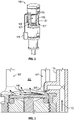
- FIG. 2 is an isometric view of aspects of the particle concentration measurement device 100 according to one or more embodiments.
- the view in FIG. 2 shows that the sensing volume 165 is open to the environment around the particle concentration measurement device 100 because of gaps between the supports 167.
- the window 140 is visible in FIG. 2 .
- the arrangement of a container 175 for compressed gas 170 and orifices 145, 155 to direct the compressed gas 170 onto the windows 140, 150 is also shown.
- the container 175 need not be arranged as shown in the exemplary embodiment of FIG. 2 . Instead, a mating orifice for a hose may be coupled to the particle concentration measurement device 100 to couple the particle concentration measurement device 100 to a source of the compressed gas 170.
- FIG. 3 is a cross-sectional view of aspects of the particle concentration measurement device 100 according to one or more embodiments.
- the view in FIG. 3 shows the orifice 145 of the container 175 that directs compressed gas 170 onto and across the window 140.
- the orifice 145 may be angled to direct the compressed gas 170 directly onto the window 140.
- the orifice 145 is angled down because the orifice 145 is above the window 140.
- the side of the sensing volume 165 adjacent to the window 140 is detailed in FIG. 3 , the arrangement may be similar on the side of the sensing volume 165 that is adjacent to the window 150.
- the orifice 155 may be angled to direct the compressed gas 170 from the same or another container 175 directly onto the window 150. According to the arrangement shown in FIG. 1 and FIG. 3 , the orifice 155 is angled up because the orifice 155 is below the window 150.
- FIG. 4 is an isometric view of aspects of the particle concentration measurement device 100 according to one or more embodiments.
- the view in FIG. 4 shows a collar 410 between the center 166 of the sensing volume 165 and the window 140.
- the collar 410 has an inner edge 420 and an outer edge 430.
- the orifice 145 is between the collar 410 and the window 140. That is, according to the arrangement shown in FIGS. 1 and 4 , the orifice 145 is below the collar 410 and above the window 140.
- the inner edge 420 is closer to the center 166 of the sensing volume 165 than the outer edge 430.
- the outer edge 430 is shaped to direct the compressed gas 170 from the orifice 145 away from the particle concentration measurement device 100 and, more specifically, away from the sensing volume 165, after it has flowed across the window 140.
- a similar collar 410 may be arranged, additionally or alternately, below the window 150 according to the arrangement shown in FIGS. 1 and 4 . That is, the orifice 155 may be below the window 150 and above the collar 410 that is closer to the window 150 than the window 140.
- FIG. 5 is a cross-sectional view of aspects of the particle concentration measurement device 100 according to one or more embodiments.
- the view in FIG. 5 illustrates the functionality of the collar 410 near the window 140.
- the outer edge 430 of the collar 410 is shaped (e.g., angled down in the exemplary illustration) so that the compressed air 170 that flowed across the window 140 is directed away from (below) the sensing volume 165.
- The may ensure that the compressed air 170 does not affect the interaction of the incident light 125 with the particle-laden gas 135 in the sensing volume 165 and, thereby, affect the accuracy of the concentration measurement by the particle concentration measurement device 100.
- an additional collar 410 or an alternate collar 410 may be arranged closer to the window 150 than the window 140.
- the outer edge 430 of that collar 410 may be shaped (e.g., angled up) so that compressed air 170 that flowed across the window 150 is directed away from (above) the sensing volume 165.
Landscapes
- Chemical & Material Sciences (AREA)
- Physics & Mathematics (AREA)
- Health & Medical Sciences (AREA)
- Life Sciences & Earth Sciences (AREA)
- Analytical Chemistry (AREA)
- Biochemistry (AREA)
- General Health & Medical Sciences (AREA)
- General Physics & Mathematics (AREA)
- Immunology (AREA)
- Pathology (AREA)
- Dispersion Chemistry (AREA)
- Investigating Or Analysing Materials By Optical Means (AREA)
Abstract
Description
- Exemplary embodiments pertain to the art of fire suppression and, in particular, to compressed gas cleaning of windows in a particle concentration measurement device.
- Fire suppression systems deploy agents to extinguish a fire. Halon, a liquified compressed gas that stops the spread of fire by chemically disrupting combustion, is being replaced as a fire-suppression agent due to its contribution to ozone depletion. Alternative fire suppressive agents include dry solid particulates that are dispersed within an environment. The distribution and concentration of the particulates within the environment are factors in the effectiveness of the fire suppression system. As such, measurement of the concentration of a fire suppression agent is an important part of the fire suppression effort using these particulates. A concentration measurement device may include windows on either end of a sensing volume.
- In one embodiment, a particle concentration measurement system includes a first window and a second window separated by a sensing volume. The system also includes one or more supports to provide structural support for the first window at a first end and for the second window at a second end, opposite the first end, of each of the one or more supports. The sensing volume defined by the one or more supports and the first window and the second window is open to an environment of the particle concentration measurement system adjacent to the one or more supports such that particle-laden gas from the environment that includes particles mixed with other materials enters the sensing volume. A first compressed gas orifice directs a compressed gas onto the first window to clean the first window and a second compressed gas orifice directs the compressed gas onto the second window to clean the second window.
- Additionally or alternatively, in this or other embodiments, the particle concentration measurement system also includes one or more containers to store the compressed gas and channel the compressed gas to the first compressed gas orifice and the second compressed gas orifice.
- Additionally or alternatively, in this or other embodiments, the particle concentration measurement system also includes a first collar disposed between the first window and a center of the sensing volume, wherein the first compressed gas orifice is between the first window and the first collar, and the first collar includes an inner edge and an outer edge, opposite the inner edge.
- Additionally or alternatively, in this or other embodiments, the particle concentration measurement system also includes a second collar disposed between the second window and the center of the sensing volume, wherein the second compressed gas orifice is between the second window and the second collar, and the second collar includes an inner edge and an outer edge, opposite the inner edge.
- Additionally or alternatively, in this or other embodiments, the inner edge of the first collar forms an opening for the first window and the inner edge of the second collar forms an opening for the second window such that the sensing volume extends from the first window to the second window.
- Additionally or alternatively, in this or other embodiments, the outer edge of the first collar and the outer edge of the second collar are shaped to channel the compressed gas away from the sensing volume.
- Additionally or alternatively, in this or other embodiments, the particle concentration measurement system also includes a light source to emit incident light into the sensing volume via a fiber optic cable. The incident light enters the sensing volume through the first window and interacts with the particle-laden gas in the sensing volume.
- Additionally or alternatively, in this or other embodiments, the particle concentration measurement system also includes a detector configured to detect light intensity following interaction in the sensing volume.
- Additionally or alternatively, in this or other embodiments, the particle concentration measurement system also includes a controller to determine a concentration of the particles in the particle-laden gas in the interaction region based on the intensity measured by the detector.
- Additionally or alternatively, in this or other embodiments, the particles act as a fire suppression agent.
- In another embodiment, a method of assembling a particle concentration measurement system includes arranging a first window and a second window separated by a sensing volume, and arranging one or more supports to provide structural support for the first window at a first end and for the second window at a second end, opposite the first end, of each of the one or more supports. The sensing volume defined by the one or more supports and the first window and the second window is open to an environment of the particle concentration measurement system adjacent to the one or more supports such that particle-laden gas from the environment that includes particles mixed with other materials enters the sensing volume. The method also includes arranging a first compressed gas orifice to direct a compressed gas onto the first window to clean the first window and arranging a second compressed gas orifice to direct the compressed gas onto the second window to clean the second window.
- Additionally or alternatively, in this or other embodiments, the method also includes disposing one or more containers to store the compressed gas and channel the compressed gas to the first compressed gas orifice and the second compressed gas orifice.
- Additionally or alternatively, in this or other embodiments, the method also includes arranging a first collar disposed between the first window and a center of the sensing volume, wherein the first compressed gas orifice is between the first window and the first collar, and the first collar includes an inner edge and an outer edge, opposite the inner edge.
- Additionally or alternatively, in this or other embodiments, the method also includes arranging a second collar disposed between the second window and the center of the sensing volume, wherein the second compressed gas orifice is between the second window and the second collar, and the second collar includes an inner edge and an outer edge, opposite the inner edge.
- Additionally or alternatively, in this or other embodiments, the arranging the first collar includes the inner edge of the first collar forming an opening for the first window and the arranging the second collar includes the inner edge of the second collar forming an opening for the second window such that the sensing volume extends from the first window to the second window.
- Additionally or alternatively, in this or other embodiments, the arranging the first collar and the second collar includes the outer edge of the first collar and the outer edge of the second collar being shaped to channel the compressed gas away from the sensing volume.
- Additionally or alternatively, in this or other embodiments, the method also includes arranging a light source to emit incident light into the sensing volume via a fiber optic cable, wherein the incident light enters the sensing volume through the first window and interacts with the particle-laden gas in the sensing volume.
- Additionally or alternatively, in this or other embodiments, the method also includes arranging a detector to detect light intensity following interaction in the sensing volume.
- Additionally or alternatively, in this or other embodiments, the method also includes configuring a controller to determine a concentration of the particles in the particle-laden gas in the interaction region based on the intensity measured by the detector.
- Additionally or alternatively, in this or other embodiments, determining the concentration of the particles includes determining the concentration of a fire suppression agent.
- The following descriptions should not be considered limiting in any way. With reference to the accompanying drawings, like elements are numbered alike:
-
FIG. 1 is a block diagram of a particle concentration measurement device that employs compressed gas to clean windows according to one or more embodiments; -
FIG. 2 is an isometric view of aspects of the particle concentration measurement device according to one or more embodiments; -
FIG. 3 is a cross-sectional view of aspects of the particle concentration measurement device according to one or more embodiments; -
FIG. 4 is an isometric view of aspects of the particle concentration measurement device according to one or more embodiments; and -
FIG. 5 is a cross-sectional view of aspects of the particle concentration measurement device according to one or more embodiments. - A detailed description of one or more embodiments of the disclosed apparatus and method are presented herein by way of exemplification and not limitation with reference to the Figures.
- As previously noted, the distribution and concentration of dry solid particulates used for fire suppression can affect the result of the suppressive effort. Thus, a fire suppression agent concentration measurement device may be used to measure concentration in real time. A set of such devices may be used in different areas of a given environment to also determine distribution. The measurements may be used to control the release of additional fire suppression agent as needed, for example.
- One approach to measuring the concentration of fire suppression agent in the environment involves transmitting light through a sensing volume in which the light interacts with a sample of gas from the environment. The sensing volume may be between two windows of the concentration measurement device. The introduction of light into the sensing volume is through a first window. The intensity of the light that has interacted with the gas from the environment is measured, and a decrease in the intensity is correlated to a concentration of the fire suppression agent in the gas. Over time, particles of the fire suppressive agent may build up on the windows. This buildup impedes light transmission through the windows, thus preventing the accurate measurement of the concentration of the fire suppression agent.
- Embodiments of the systems and methods detailed herein relate to compressed gas cleaning of windows in a particle concentration measurement device. The particles of interest may be particles of a fire suppression agent, for example. As detailed, compressed gas such as nitrogen or air is blown against and across the windows of the particle concentration measurement device through which light is transmitted. In exemplary embodiments, a collar may be added between each window and the sensing volume to ensure that the compressed gas that flows across the window does not affect the particle concentration measurement in the sensing volume. While windows are specifically depicted and discussed, the particle concentration measurement device according to alternate embodiments may have optically sensitive components (e.g., light emitter, light receivers, mirror) that are directly exposed to the environment. The compressed air flow detailed herein is equally applicable to such an alternate embodiment to prevent fire suppression agent from settling on the optically sensitive components.
-
FIG. 1 is a block diagram of a particleconcentration measurement device 100 that employs compressed gas to cleanwindows concentration measurement device 100 is disposed in an environment in which a solid particle fire suppression agent is dispersed, for example. Theparticles 137 mix with air and other materials in the environment to create particle-laden gas 135. The particleconcentration measurement device 100 measures the concentration of theparticles 137 of fire suppression agent in the particle-laden gas 135 in the environment. - The particle-
laden gas 135 flows freely into asensing volume 165, which is open to the environment. Thesupports 167 that provide structural support for thewindows sensing volume 165 but, instead, define gaps through which particle-laden gas 135 may flow through the sendingvolume 165. Acenter 166 of thesensing volume 165, which is defined by thesupports 167 and thewindows incident light 125 and particle-laden gas 135 in thesensing volume 165 forms the basis of determining the concentration ofparticles 137 in the particle-laden gas 135. - A
light source 110 emitsincident light 125 via afiber optic cable 120 into thesensing volume 165. Specifically, theincident light 125 is directed into thesensing volume 165 through thewindow 140 and exits thesensing volume 165 through thewindow 150. The incident light 125 that has interacted with particle-laden gas 135 in thesensing volume 165 is reflected by amirror 160 as reflectedlight 130. The reflected light 130 re-enters thesensing volume 165 through thewindow 150 and is exits thesensing volume 165 through thewindow 140. The reflectedlight 130 and, more specifically, intensity of the reflectedlight 130 is detected by adetector 115. Acontroller 105 then uses the measured intensity of the reflected light 130 to determine the concentration of the particles 137 (e.g., of fire suppression agent) in the particle-laden gas 135. A mapping of measured intensity to concentration may be in the form of a look-up table, for example. According to an alternate embodiment, thedetector 115, and optionally also thecontroller 105, may be positioned to replace themirror 160. In that case, incident light 125 that flowed through thesensing volume 165 is detected on the other side of thewindow 150 and there is noreflected light 130. - As previously noted, if particle-
laden gas 135 and/or theparticles 137 settle on thewindows windows container 175 of thecompressed gas 170 channels thecompressed gas 170 toorifices compressed gas 170 onto and across thewindows container 175 is shown, each of theorifices different container 175 in alternate embodiments. -
FIG. 2 is an isometric view of aspects of the particleconcentration measurement device 100 according to one or more embodiments. The view inFIG. 2 shows that thesensing volume 165 is open to the environment around the particleconcentration measurement device 100 because of gaps between thesupports 167. Thewindow 140 is visible inFIG. 2 . The arrangement of acontainer 175 forcompressed gas 170 andorifices compressed gas 170 onto thewindows container 175 need not be arranged as shown in the exemplary embodiment ofFIG. 2 . Instead, a mating orifice for a hose may be coupled to the particleconcentration measurement device 100 to couple the particleconcentration measurement device 100 to a source of thecompressed gas 170. -
FIG. 3 is a cross-sectional view of aspects of the particleconcentration measurement device 100 according to one or more embodiments. The view inFIG. 3 shows theorifice 145 of thecontainer 175 that directs compressedgas 170 onto and across thewindow 140. As shown, theorifice 145 may be angled to direct thecompressed gas 170 directly onto thewindow 140. According to the arrangement shown inFIG. 1 andFIG. 3 , theorifice 145 is angled down because theorifice 145 is above thewindow 140. While the side of thesensing volume 165 adjacent to thewindow 140 is detailed inFIG. 3 , the arrangement may be similar on the side of thesensing volume 165 that is adjacent to thewindow 150. That is, theorifice 155 may be angled to direct thecompressed gas 170 from the same or anothercontainer 175 directly onto thewindow 150. According to the arrangement shown inFIG. 1 andFIG. 3 , theorifice 155 is angled up because theorifice 155 is below thewindow 150. -
FIG. 4 is an isometric view of aspects of the particleconcentration measurement device 100 according to one or more embodiments. The view inFIG. 4 shows acollar 410 between thecenter 166 of thesensing volume 165 and thewindow 140. Thecollar 410 has aninner edge 420 and anouter edge 430. Theorifice 145 is between thecollar 410 and thewindow 140. That is, according to the arrangement shown inFIGS. 1 and4 , theorifice 145 is below thecollar 410 and above thewindow 140. Theinner edge 420 is closer to thecenter 166 of thesensing volume 165 than theouter edge 430. As discussed with reference toFIG. 5 , theouter edge 430 is shaped to direct thecompressed gas 170 from theorifice 145 away from the particleconcentration measurement device 100 and, more specifically, away from thesensing volume 165, after it has flowed across thewindow 140. Asimilar collar 410 may be arranged, additionally or alternately, below thewindow 150 according to the arrangement shown inFIGS. 1 and4 . That is, theorifice 155 may be below thewindow 150 and above thecollar 410 that is closer to thewindow 150 than thewindow 140. -
FIG. 5 is a cross-sectional view of aspects of the particleconcentration measurement device 100 according to one or more embodiments. The view inFIG. 5 illustrates the functionality of thecollar 410 near thewindow 140. As shown, theouter edge 430 of thecollar 410 is shaped (e.g., angled down in the exemplary illustration) so that thecompressed air 170 that flowed across thewindow 140 is directed away from (below) thesensing volume 165. The may ensure that thecompressed air 170 does not affect the interaction of the incident light 125 with the particle-laden gas 135 in thesensing volume 165 and, thereby, affect the accuracy of the concentration measurement by the particleconcentration measurement device 100. - As noted with reference to
FIG. 4 , anadditional collar 410 or analternate collar 410 may be arranged closer to thewindow 150 than thewindow 140. Based on the arrangement shown inFIGS. 1 ,4, and 5 , theouter edge 430 of thatcollar 410 may be shaped (e.g., angled up) so thatcompressed air 170 that flowed across thewindow 150 is directed away from (above) thesensing volume 165. - The terminology used herein is for the purpose of describing particular embodiments only and is not intended to be limiting of the present disclosure. As used herein, the singular forms "a", "an" and "the" are intended to include the plural forms as well, unless the context clearly indicates otherwise. It will be further understood that the terms "comprises" and/or "comprising," when used in this specification, specify the presence of stated features, integers, steps, operations, elements, and/or components, but do not preclude the presence or addition of one or more other features, integers, steps, operations, element components, and/or groups thereof.
- While the present disclosure has been described with reference to an exemplary embodiment or embodiments, it will be understood by those skilled in the art that various changes may be made and equivalents may be substituted for elements thereof without departing from the scope of the present disclosure. In addition, many modifications may be made to adapt a particular situation or material to the teachings of the present disclosure without departing from the essential scope thereof. Therefore, it is intended that the present disclosure not be limited to the particular embodiment disclosed as the best mode contemplated for carrying out this present disclosure, but that the present disclosure will include all embodiments falling within the scope of the claims.
Claims (15)
- A particle concentration measurement system comprising:a first window and a second window separated by a sensing volume;one or more supports configured to provide structural support for the first window at a first end and for the second window at a second end, opposite the first end, of each of the one or more supports, wherein the sensing volume defined by the one or more supports and the first window and the second window is open to an environment of the particle concentration measurement system adjacent to the one or more supports such that particle-laden gas from the environment that includes particles mixed with other materials enters the sensing volume;a first compressed gas orifice configured to direct a compressed gas onto the first window to clean the first window; anda second compressed gas orifice configured to direct the compressed gas onto the second window to clean the second window.
- The particle concentration measurement system according to claim 1, further comprising a first collar disposed between the first window and a center of the sensing volume, wherein the first compressed gas orifice is between the first window and the first collar, and the first collar includes an inner edge and an outer edge, opposite the inner edge.
- The particle concentration measurement system according to claim 2, further comprising a second collar disposed between the second window and the center of the sensing volume, wherein the second compressed gas orifice is between the second window and the second collar, and the second collar includes an inner edge and an outer edge, opposite the inner edge.
- The particle concentration measurement system according to claim 3, wherein the inner edge of the first collar forms an opening for the first window and the inner edge of the second collar forms an opening for the second window such that the sensing volume extends from the first window to the second window.
- The particle concentration measurement system according to claim 3 or claim 4, wherein the outer edge of the first collar and the outer edge of the second collar are shaped to channel the compressed gas away from the sensing volume.
- A method of assembling a particle concentration measurement system, the method comprising:arranging a first window and a second window separated by a sensing volume;arranging one or more supports to provide structural support for the first window at a first end and for the second window at a second end, opposite the first end, of each of the one or more supports, wherein the sensing volume defined by the one or more supports and the first window and the second window is open to an environment of the particle concentration measurement system adjacent to the one or more supports such that particle-laden gas from the environment that includes particles mixed with other materials enters the sensing volume;arranging a first compressed gas orifice to direct a compressed gas onto the first window to clean the first window; andarranging a second compressed gas orifice to direct the compressed gas onto the second window to clean the second window.
- The particle concentration measurement system of any of claims 1-5, further comprising one or more containers configured to store the compressed gas and channel the compressed gas to the first compressed gas orifice and the second compressed gas orifice;
or the method according to claim 6, further comprising disposing one or more containers to store the compressed gas and channel the compressed gas to the first compressed gas orifice and the second compressed gas orifice. - The method according to claim 6 or claim 7, further comprising arranging a first collar disposed between the first window and a center of the sensing volume, wherein the first compressed gas orifice is between the first window and the first collar, and the first collar includes an inner edge and an outer edge, opposite the inner edge.
- The method according to claim 8, further comprising arranging a second collar disposed between the second window and the center of the sensing volume, wherein the second compressed gas orifice is between the second window and the second collar, and the second collar includes an inner edge and an outer edge, opposite the inner edge.
- The method according to claim 9, wherein the arranging the first collar includes the inner edge of the first collar forming an opening for the first window and the arranging the second collar includes the inner edge of the second collar forming an opening for the second window such that the sensing volume extends from the first window to the second window.
- The method according to claim 9 or claim 10, wherein the arranging the first collar and the second collar includes the outer edge of the first collar and the outer edge of the second collar being shaped to channel the compressed gas away from the sensing volume.
- The particle concentration measurement system of any of claims 1-5, or 7, further comprising a light source configured to emit incident light into the sensing volume via a fiber optic cable, wherein the incident light enters the sensing volume through the first window and interacts with the particle-laden gas in the sensing volume; or
the method according to any of claims 6-11, further comprising arranging a light source to emit incident light into the sensing volume via a fiber optic cable, wherein the incident light enters the sensing volume through the first window and interacts with the particle-laden gas in the sensing volume. - The particle concentration measurement system of claim 12 further comprising a detector configured to detect light intensity following interaction in the sensing volume; or
the method according to any of claims 12, further comprising arranging a detector to detect light intensity following interaction in the sensing volume. - The particle concentration measurement system according to claim 13, further comprising a controller configured to determine a concentration of the particles in the particle-laden gas in the interaction region based on the intensity measured by the detector; or
the method according to claim 13, further comprising configuring a controller to determine a concentration of the particles in the particle-laden gas in the interaction region based on the intensity measured by the detector. - The particle concentration measurement system according to any of claims 1-5, 7, or 12-14, wherein the particles act as a fire suppression agent; or
the method according to any of claims 6-14, wherein determining the concentration of the particles includes determining the concentration of a fire suppression agent.
Applications Claiming Priority (1)
| Application Number | Priority Date | Filing Date | Title |
|---|---|---|---|
| US17/489,644 US12055477B2 (en) | 2021-09-29 | 2021-09-29 | Compressed gas cleaning of windows in particle concentration measurement device |
Publications (1)
| Publication Number | Publication Date |
|---|---|
| EP4160185A1 true EP4160185A1 (en) | 2023-04-05 |
Family
ID=83444826
Family Applications (1)
| Application Number | Title | Priority Date | Filing Date |
|---|---|---|---|
| EP22192242.0A Pending EP4160185A1 (en) | 2021-09-29 | 2022-08-25 | Compressed gas cleaning of windows in particle concentration measurement device |
Country Status (2)
| Country | Link |
|---|---|
| US (1) | US12055477B2 (en) |
| EP (1) | EP4160185A1 (en) |
Families Citing this family (1)
| Publication number | Priority date | Publication date | Assignee | Title |
|---|---|---|---|---|
| CN119290699B (en) * | 2024-12-13 | 2025-04-18 | 中国科学技术大学 | Airflow protection type optical fiber probe, powder concentration measurement system and method |
Citations (6)
| Publication number | Priority date | Publication date | Assignee | Title |
|---|---|---|---|---|
| FR2667941A1 (en) * | 1990-10-16 | 1992-04-17 | Volkswagen Ag | DEVICE ALLOWING DYNAMIC MEASUREMENT OF THE DENSITY OF PARTICLES IN A GAS FLOW. |
| GB2288231A (en) * | 1991-10-22 | 1995-10-11 | Marconi Gec Ltd | Combined LED and photodiode assembly |
| US20150077754A1 (en) * | 2013-07-12 | 2015-03-19 | Siemens Aktiengesellschaft | Process interface of a process gas analyzer operating by the transmitted light method |
| US20160003736A1 (en) * | 2013-02-26 | 2016-01-07 | Siemens Aktiengesellschaft | Dust line with optical sensor, and method for measuring the composition of dust |
| US20160033763A1 (en) * | 2014-07-29 | 2016-02-04 | Nanometrics Incorporated | Protected lens cover plate for an optical metrology device |
| DE202015102319U1 (en) * | 2015-05-06 | 2016-08-09 | Sick Ag | Analysis device for analyzing a gas flow |
Family Cites Families (18)
| Publication number | Priority date | Publication date | Assignee | Title |
|---|---|---|---|---|
| US3628028A (en) * | 1968-03-01 | 1971-12-14 | Honeywell Inc | Window cleaning apparatus for photometric instruments |
| US3728071A (en) * | 1972-07-10 | 1973-04-17 | American Air Filter Co | Burner assembly |
| US4836689A (en) | 1986-02-27 | 1989-06-06 | Rosemount Inc. | Asymmetric purge air system for cleaning a lens |
| US4896047A (en) * | 1988-04-11 | 1990-01-23 | Westinghouse Electric Corp. | Method and apparatus of periodically obtaining accurate opacity monitor readings of an exhaust gas stream |
| US5191878A (en) * | 1990-04-12 | 1993-03-09 | Olympus Optical Co., Ltd. | Endoscope device |
| GB2260809B (en) | 1991-10-22 | 1996-04-03 | Marconi Gec Ltd | Exhaust gas particle sensor |
| US6181426B1 (en) * | 1998-04-03 | 2001-01-30 | Mcdonnell Douglas Corporation | Gas concentration monitoring system |
| US6421127B1 (en) * | 1999-07-19 | 2002-07-16 | American Air Liquide, Inc. | Method and system for preventing deposition on an optical component in a spectroscopic sensor |
| JP3679064B2 (en) | 2002-03-20 | 2005-08-03 | 日機装株式会社 | Measuring cell for particle size sensor |
| US7319524B2 (en) | 2005-03-28 | 2008-01-15 | Honeywell International, Inc. | Air purged optical densitometer |
| US7554103B2 (en) * | 2006-06-26 | 2009-06-30 | Applied Materials, Inc. | Increased tool utilization/reduction in MWBC for UV curing chamber |
| JP5108595B2 (en) * | 2008-04-04 | 2012-12-26 | オリンパスメディカルシステムズ株式会社 | Endoscope, endoscope with tip cap, and cleaning sheath for endoscope |
| US20120236323A1 (en) * | 2009-12-04 | 2012-09-20 | Siemens Aktiengesellschaft | Method for Determining the Optical Measurement Path Length in a Duct Gas Monitoring System |
| DE102017128486A1 (en) * | 2017-11-30 | 2019-06-06 | Airbus Operations Gmbh | An aircraft and method for controlling an extinguishing agent concentration in a cargo hold |
| CN207689323U (en) | 2017-12-28 | 2018-08-03 | 深圳市翠云谷科技有限公司 | A kind of gas particles object sampling area air curtain protection system |
| WO2019234978A1 (en) * | 2018-06-08 | 2019-12-12 | ホーチキ株式会社 | Sensor |
| CN209559715U (en) | 2019-02-26 | 2019-10-29 | 南通恒道昇光电科技有限公司 | A kind of dust detection sensor scattered, light decay principle based on light |
| CN111474095B (en) | 2020-05-26 | 2022-04-01 | 江苏友穗传感科技股份有限公司 | Air curtain structure oil smoke sensor |
-
2021
- 2021-09-29 US US17/489,644 patent/US12055477B2/en active Active
-
2022
- 2022-08-25 EP EP22192242.0A patent/EP4160185A1/en active Pending
Patent Citations (6)
| Publication number | Priority date | Publication date | Assignee | Title |
|---|---|---|---|---|
| FR2667941A1 (en) * | 1990-10-16 | 1992-04-17 | Volkswagen Ag | DEVICE ALLOWING DYNAMIC MEASUREMENT OF THE DENSITY OF PARTICLES IN A GAS FLOW. |
| GB2288231A (en) * | 1991-10-22 | 1995-10-11 | Marconi Gec Ltd | Combined LED and photodiode assembly |
| US20160003736A1 (en) * | 2013-02-26 | 2016-01-07 | Siemens Aktiengesellschaft | Dust line with optical sensor, and method for measuring the composition of dust |
| US20150077754A1 (en) * | 2013-07-12 | 2015-03-19 | Siemens Aktiengesellschaft | Process interface of a process gas analyzer operating by the transmitted light method |
| US20160033763A1 (en) * | 2014-07-29 | 2016-02-04 | Nanometrics Incorporated | Protected lens cover plate for an optical metrology device |
| DE202015102319U1 (en) * | 2015-05-06 | 2016-08-09 | Sick Ag | Analysis device for analyzing a gas flow |
Also Published As
| Publication number | Publication date |
|---|---|
| US20230095478A1 (en) | 2023-03-30 |
| US12055477B2 (en) | 2024-08-06 |
Similar Documents
| Publication | Publication Date | Title |
|---|---|---|
| JP6190666B2 (en) | Concentration and particle size measurement of solids, aerosols, vapors, liquids and gases | |
| KR101904180B1 (en) | Gas detector apparatus | |
| EP0698262A1 (en) | Smoke detector sensitivity testing apparatus | |
| US12055477B2 (en) | Compressed gas cleaning of windows in particle concentration measurement device | |
| US11781969B2 (en) | Clean gas curtain to prevent particle buildup during concentration measurement | |
| BRPI1003533B1 (en) | SENSOR HEAD, AND, CALIBRATION AND MEASUREMENT SYSTEMS FOR A DRY POWDER AGENT | |
| EP3635699B1 (en) | Chamberless smoke detector with indoor air quality detection and monitoring | |
| CA2913380A1 (en) | Powder flow monitor and method for in-flight measurement of a flow of powder | |
| US10620130B2 (en) | Measurement device for measuring fine particulate matter in at least one volume of air for a vehicle, particularly for a motor vehicle | |
| US7869037B2 (en) | Particle size distribution measuring device | |
| US20230417666A1 (en) | Calibration of an optical detector using a micro-flow chamber | |
| US6476911B1 (en) | Backscatter instrument for monitoring particulate levels in a gas stream | |
| EP3894838B1 (en) | Calibration of an optical detector | |
| CN104280342B (en) | The procedural interface of the process gas analyzer worked according to light transmission | |
| KR101275104B1 (en) | Optical analysis device | |
| US20210404954A1 (en) | Fire extinguishing agent concentration measuring system and method of measuring a fire extinguishing agent within an environment | |
| AU736174B2 (en) | Device for measuring the concentration of airborne fibers | |
| US11609179B2 (en) | Apparatus and method for monitoring particle flow in a stack | |
| US20210396641A1 (en) | Fire extinguishing agent concentration measuring system and method | |
| KR102509110B1 (en) | Light Back Scattering Portable Particulate Monitor in Stack or Duct | |
| JPS58210819A (en) | Method for testing leakage of air filter and its device | |
| JPS639849A (en) | Corpuscle detecting device | |
| CN121393054A (en) | Optical fiber smoke monitoring device and optical fiber smoke monitoring method | |
| EP3436798A1 (en) | Method for measuring the properties of particles in a medium and a device for measuring the properties of particles in a flue gas | |
| CN108333117A (en) | In-situ type gas in pipelines detection device and its working method |
Legal Events
| Date | Code | Title | Description |
|---|---|---|---|
| PUAI | Public reference made under article 153(3) epc to a published international application that has entered the european phase |
Free format text: ORIGINAL CODE: 0009012 |
|
| STAA | Information on the status of an ep patent application or granted ep patent |
Free format text: STATUS: THE APPLICATION HAS BEEN PUBLISHED |
|
| AK | Designated contracting states |
Kind code of ref document: A1 Designated state(s): AL AT BE BG CH CY CZ DE DK EE ES FI FR GB GR HR HU IE IS IT LI LT LU LV MC MK MT NL NO PL PT RO RS SE SI SK SM TR |
|
| STAA | Information on the status of an ep patent application or granted ep patent |
Free format text: STATUS: REQUEST FOR EXAMINATION WAS MADE |
|
| 17P | Request for examination filed |
Effective date: 20231005 |
|
| RBV | Designated contracting states (corrected) |
Designated state(s): AL AT BE BG CH CY CZ DE DK EE ES FI FR GB GR HR HU IE IS IT LI LT LU LV MC MK MT NL NO PL PT RO RS SE SI SK SM TR |
|
| STAA | Information on the status of an ep patent application or granted ep patent |
Free format text: STATUS: EXAMINATION IS IN PROGRESS |
|
| 17Q | First examination report despatched |
Effective date: 20241128 |