EP4160144B1 - Surveying system - Google Patents
Surveying system Download PDFInfo
- Publication number
- EP4160144B1 EP4160144B1 EP22197653.3A EP22197653A EP4160144B1 EP 4160144 B1 EP4160144 B1 EP 4160144B1 EP 22197653 A EP22197653 A EP 22197653A EP 4160144 B1 EP4160144 B1 EP 4160144B1
- Authority
- EP
- European Patent Office
- Prior art keywords
- distance measurement
- height
- measuring device
- distance
- low
- Prior art date
- Legal status (The legal status is an assumption and is not a legal conclusion. Google has not performed a legal analysis and makes no representation as to the accuracy of the status listed.)
- Active
Links
Images


Classifications
-
- G—PHYSICS
- G01—MEASURING; TESTING
- G01C—MEASURING DISTANCES, LEVELS OR BEARINGS; SURVEYING; NAVIGATION; GYROSCOPIC INSTRUMENTS; PHOTOGRAMMETRY OR VIDEOGRAMMETRY
- G01C15/00—Surveying instruments or accessories not provided for in groups G01C1/00 - G01C13/00
- G01C15/002—Active optical surveying means
-
- G—PHYSICS
- G01—MEASURING; TESTING
- G01B—MEASURING LENGTH, THICKNESS OR SIMILAR LINEAR DIMENSIONS; MEASURING ANGLES; MEASURING AREAS; MEASURING IRREGULARITIES OF SURFACES OR CONTOURS
- G01B11/00—Measuring arrangements characterised by the use of optical techniques
- G01B11/30—Measuring arrangements characterised by the use of optical techniques for measuring roughness or irregularity of surfaces
- G01B11/306—Measuring arrangements characterised by the use of optical techniques for measuring roughness or irregularity of surfaces for measuring evenness
-
- G—PHYSICS
- G06—COMPUTING OR CALCULATING; COUNTING
- G06T—IMAGE DATA PROCESSING OR GENERATION, IN GENERAL
- G06T7/00—Image analysis
- G06T7/0002—Inspection of images, e.g. flaw detection
- G06T7/0004—Industrial image inspection
-
- G—PHYSICS
- G06—COMPUTING OR CALCULATING; COUNTING
- G06T—IMAGE DATA PROCESSING OR GENERATION, IN GENERAL
- G06T7/00—Image analysis
- G06T7/60—Analysis of geometric attributes
-
- H—ELECTRICITY
- H04—ELECTRIC COMMUNICATION TECHNIQUE
- H04N—PICTORIAL COMMUNICATION, e.g. TELEVISION
- H04N7/00—Television systems
- H04N7/18—Closed-circuit television [CCTV] systems, i.e. systems in which the video signal is not broadcast
- H04N7/183—Closed-circuit television [CCTV] systems, i.e. systems in which the video signal is not broadcast for receiving images from a single remote source
-
- G—PHYSICS
- G06—COMPUTING OR CALCULATING; COUNTING
- G06T—IMAGE DATA PROCESSING OR GENERATION, IN GENERAL
- G06T2207/00—Indexing scheme for image analysis or image enhancement
- G06T2207/10—Image acquisition modality
- G06T2207/10028—Range image; Depth image; 3D point clouds
-
- G—PHYSICS
- G06—COMPUTING OR CALCULATING; COUNTING
- G06T—IMAGE DATA PROCESSING OR GENERATION, IN GENERAL
- G06T2207/00—Indexing scheme for image analysis or image enhancement
- G06T2207/30—Subject of image; Context of image processing
- G06T2207/30108—Industrial image inspection
- G06T2207/30132—Masonry; Concrete
Definitions
- the present disclosure relates to a surveying system which determines an unevenness state of an object surface.
- a measuring rod is inserted into a concrete at a placed part, and a height of the concrete of the placed part is actually measured at predetermined intervals.
- a leveling height (the unevenness state) is measured, for instance, by stretching a string at a predetermined height after the ground leveling, and if any deviation or unevenness with respect to the set height is occurred, correction of filling or removing the soil is performed.
- US 2021/214922 A1 discloses a display system for a work vehicle.
- a camera captures an image of a surrounding environment of a work vehicle and a shape sensor measures a three-dimensional shape of the surrounding environment and outputs 3D shape data indicative of the three-dimensional shape.
- a controller generates display image data that represents a display image of the surrounding environment of the work vehicle.
- the height measuring device is adapted to form a horizontal reference plane with a known height
- the object is a photodetector for detecting the horizontal reference plane
- the arithmetic control module is configured to calculate a height of a measurement reference position of the distance measurement sensor with respect to the horizontal reference plane based on a detection result of the photodetector and to calculate the high-low information of the construction surface based on a measurement result of the distance measurement sensor.
- the height measuring device is a surveying instrument which is provided at a known height, has a TS communication module configured to transmit measurement results and has a tracking function, the high-low measuring device has a terminal communication module configured to receive measurement results from the TS communication module, the object is a prism, and the arithmetic control module is configured to acquire the height information of the prism via the terminal communication module, to calculate a height of the measurement reference position of the distance measurement sensor based on the height information of the prism, and to calculate the high-low information of the construction surface based on a measurement result of the distance measurement sensor.
- the high-low measuring device further comprises a tilt sensor
- the arithmetic control module is configured to correct the high-low information based on a detection result of the tilt sensor.
- the high-low measuring device further comprises a tilt sensor and is constituted as a handheld type, and the arithmetic control module is configured to correct the high-low information based on a detection result of the tilt sensor.
- the distance measurement sensor is a distance measurement camera.
- the distance measurement sensor is a parallax camera.
- the distance measurement sensor is constituted of a projector for projecting a pattern for measuring distance and a camera provided to produce a parallax with respect to the projector.
- the distance measurement sensor is a laser length measuring device, and the distance measurement sensor irradiates laser beams of a plurality of different colors, and the arithmetic control module is configured to select a color of a laser beam in correspondence with the high-low information.
- the surveying system comprises a height measuring device and a high-low measuring device, wherein the high-low measuring device comprises an object measured by the height measuring device, a distance measurement sensor which is provided in a known relationship with the object and measures a distance to a construction surface, a projecting device for projecting a high-low information, and an arithmetic control module, wherein the arithmetic control module is configured to calculate a high-low information of the construction surface based on a height information of the object measured by the height measuring device and a distance information measured by the distance measurement sensor, and wherein the projecting device is configured to project the high-low information onto the construction surface.
- the high-low measuring device comprises an object measured by the height measuring device, a distance measurement sensor which is provided in a known relationship with the object and measures a distance to a construction surface, a projecting device for projecting a high-low information, and an arithmetic control module, wherein the arithmetic control module is configured to calculate a high-low information of the
- FIG.1 shows general features of a surveying system according to a first embodiment, and the surveying system is mainly constituted of a height measuring device 1 and a high-low measuring device 2. It is to be noted that, in FIG.1 , a reference numeral 4 denotes an unevenness map (to be described later).
- a laser level planer 3 is used as the height measuring device 1.
- the laser level planer 3 forms a horizontal reference plane with a predetermined height by a laser beam.
- the horizontal reference plane may be formed by rotatably irradiating the laser beam on a horizontal plane or may be formed by horizontally irradiating a fan-shaped laser beam.
- a horizontal reference plane O is formed by rotatably irradiating the laser beam is described.
- the laser level planer 3 is installed at a necessary position via a support device such as a tripod.
- the laser level planer 3 mainly includes a control module 5, a first tilt sensor 6, a laser beam irradiation module 7, a leveling module 8, a horizontal rotation driving module 9, an operation module 11, and a display unit 12.
- the first tilt sensor 6 detects a tilt of the laser level planer 3 with respect to the horizontality, that is, a tilt of a laser beam as irradiated with respect to the horizontality. A detection result of the first tilt sensor 6 is input to the control module 5.
- the control module 5 drives the leveling module 8 based on a detection result of the first tilt sensor 6, and adjusts the laser level planer 3 to the horizontality.
- the control module 5 makes the laser beam irradiation module 7 to irradiate the laser beam, makes the horizontal rotation driving module 9 to rotate the laser beam irradiation module 7, and rotatably irradiates the laser beam such that the horizontal reference plane O is formed.
- the laser level planer 3 is installed so that the horizontal reference plane O is at a known height. For instance, a height of the horizontal reference plane O from a floor surface serving as a reference is known by actual measurements or based on specifications of the laser level planer 3 and the like. When the known horizontal reference plane O is formed, the height of an object can be measured with reference to the horizontal reference plane O.
- An instruction to turn ON/OFF operations of the laser level planer 3, settings of operation conditions, and the like are input to the control module 5 from the operation module 11, and an operation state and the like are displayed on the display unit 12.
- the high-low measuring device 2 includes a pole 14, a photodetector 15 as an object to be measured which is provided at a necessary height of the pole 14, a distance measurement sensor 16 provided at an upper end of the pole 14, a projector 17 as a projecting device, a second tilt sensor 18, and an arithmetic control module 19.
- the photodetector 15 and the distance measurement sensor 16 are provided in a known positional relationship.
- the photodetector 15 has a photodetection sensor 21 which extends in an up-and-down direction and has a predetermined length, and the photodetection sensor 21 detects the laser beam and produces a detecting signal.
- the photodetection sensor 21 has a photodetection reference position (for instance, the center of the up-and-down direction of the photodetection sensor 21 or a lower end of the photodetection sensor 21), and the photodetection reference position is a known position in the high-low measuring device 2. For instance, a distance between the photodetection reference position and the lower end of the pole 14 is known.
- the detecting signal includes a photodetecting signal and a detecting position information.
- As the detecting position information a deviation with respect to the photodetection reference position and the like are included. Therefore, based on the detecting signal, a height of the photodetection reference position with respect to the horizontal reference plane O is able to be measured.
- the detecting signal is input to the arithmetic control module 19.
- the distance measurement sensor 16 is directed downward and measures a distance to the ground surface, and various kinds of distance measurement sensors 16 can be adopted.
- a distance measurement camera 22 is used as the distance measurement sensor 16.
- the distance measurement camera 22 has an image pickup element consisting of many pixels, emits a distance measuring light for each pixel, receives a reflected light for each pixel, performs the distance measurement based on TOF (Time Of Flight) for each pixel, and planarly acquires the distance measurement data like an image.
- the distance measuring light may be scanned with a high-speed and the measurement may be planarly performed.
- the distance measurement data is input to the arithmetic control module 19.
- the distance measurement camera 22 has a measurement reference position, and a distance measured by the distance measurement camera 22 is a distance from the measurement reference position. A distance between the measurement reference position and the lower end of the pole 14 is also known. Further, a relationship between the measurement reference position of the distance measurement camera 22 and a photodetection reference position of the photodetection sensor 21 is known, and a vertical distance between the measurement reference position and the photodetection reference position is also known.
- a relationship between the measurement reference position and a reference point of a projection optical system of the projector 17 is known, and an optical axis of the distance measurement camera 22 and an optical axis of the projector 17 are parallel or substantially parallel, and a distance between both the optical axes is also known.
- the second tilt sensor 18 detects a tilt of the distance measurement camera 22 with respect to the horizontality or a tilt of the optical axis of the distance measurement camera 22 with respect to the verticality. Alternatively, a tilt of the pole 14 with respect to the verticality is detected. A tilt detection result of the second tilt sensor 18 is input to the arithmetic control module 19.
- the optical axis of the distance measurement camera 22 is set parallel to the pole 14. It is to be noted that, when the second tilt sensor 18 is configured to detect a tilt of the pole 14 with respect to the verticality, the optical axis of the distance measurement camera 22 tilts with respect to the pole 14 at a known angle.
- the second tilt sensor 18 may be incorporated in the arithmetic control module 19. Further, as the second tilt sensor 18, various kinds of IMU sensors such as an acceleration sensor or a gyroscope sensor can be used.
- the arithmetic control module 19 includes an arithmetic processing module 24 and a storage module 25.
- arithmetic processing module 24 a CPU specialized to the present embodiment, a general-purpose CPU, an embedded CPU, a microprocessor, or the like is used.
- the storage module 25 a semiconductor memory such as a RAM, a ROM, or a Flash ROM, or a DRAM, or a magnetic recording memory such as an HDD is used.
- the arithmetic processing module 24 develops various kinds of programs stored in the storage module 25, and performs necessary processing and operations.
- the programs include, for instance, a control program for integrally controlling the synchronization of the distance measurement camera 22 and the projector 17 or the like, a distance measurement program for making the distance measurement camera 22 to perform the image pickup and the distance measurement, an arithmetic program for calculating the three-dimensional data based on the distance measurement data, a program for calculating a video signal based on the three-dimensional data, and the like.
- the high-low state includes a state of a deviation with respect to a set height of an object surface to be measured, a state of irregularities (unevenness) with respect to a set plane, and a state of a tilt with respect to a horizontal plane.
- the high-low information includes an information of a deviation with respect to a set height of an object surface, an information of unevenness with respect to a set plane, and an information of a state of a tilt with respect to a horizontal plane.
- a reference numeral 27 denotes a floor surface serving as a reference
- the laser level planer 3 is installed at a known height with respect to the floor surface 27 and forms a horizontal reference plane O of a known height with respect to the floor surface 27.
- a measurer butts the pole 14 on the construction floor surface 28 and supports the high-low measuring device 2 vertically or substantially vertically.
- a vertical state of the high-low measuring device 2 is detected by the second tilt sensor 18.
- a reference sign O1 denotes a horizontal line running through a measurement reference position of the distance measurement camera 22
- a reference sign 02 denotes a horizontal line running through a photodetection reference position of the photodetection sensor 21.
- the construction finished surface 28a is set to a height difference D with respect to the horizontal reference plane O such that a predetermined placing thickness can be obtained.
- the measurement reference position and the photodetection reference position have the known relationship, and a distance between O1 and O2 has the known value d. Further, a deviation ⁇ between a laser beam receiving position of the photodetection sensor 21 and the photodetection reference position (that is, a deviation ⁇ between the horizontal reference plane O and the photodetection reference position) is provided, and a distance measurement value S (that is, a distance between the measurement reference position of the distance measurement camera 22 and a construction surface 28b) of the construction surface (a concrete placing surface) 28b as measured by the distance measurement camera 22 is provided.
- the unevenness ⁇ F of the construction surface 28b with reference to the construction finished surface 28a is acquired by the following expression.
- ⁇ F D + d ⁇ ⁇ ⁇ S
- ⁇ is + above the photodetection reference position and - below the same.
- a positive value indicates a state which is convex compared with the construction finished surface 28a and a negative value indicates a state which is concave compared to the same.
- the height difference D and the distance d between the measurement reference position and the photodetection reference position are set in the arithmetic control module 19 in advance, and a distance measurement result of the distance measurement camera 22 and a detecting signal of the photodetection sensor 21 are input to the arithmetic control module 19, respectively.
- the arithmetic control module 19 calculates the unevenness ⁇ F based on the height difference D, the distance d, the distance measurement result, and the detecting signal.
- the distance measurement camera 22 is capable of performing the distance measurement in units of pixel of the image pickup element.
- the arithmetic control module 19 calculates the unevenness ⁇ F in units of pixel and thereby acquires an unevenness ⁇ F distribution of an entire angle of field of the distance measurement camera 22.
- the arithmetic control module 19 classifies the unevenness ⁇ F with the use of a threshold value set in the storage module 25, and can create an unevenness map 4.
- the unevenness ⁇ F is + with respect to the construction finished surface 28a
- a warm color group is used, and the color density or the color tone is made darker for each 3 mm increase, for instance.
- a cool color group is used, and the color density or the color tone is made darker for each 3 mm decrease, for instance.
- the unevenness map 4 shown in FIG.1 the unevenness state is indicated by the shading.
- the threshold value for classifying can be appropriately set to 5 mm or 1 cm, for instance, without being restricted to 3 mm. Further, the classifying may be indicated in one color and the shading only.
- the arithmetic control module 19 inputs the created unevenness map to the projector 17 as a video signal, and the unevenness map 4 is projected onto the construction surface 28b by the projector 17.
- a position and a range of the unevenness map 4 to be projected coincide with a position and a distance measurement range as measured by the distance measurement camera 22, and the unevenness information of the construction surface 28b is accurately displayed by the unevenness map 4. Further, a worker can visually confirm the unevenness state of the construction surface 28b from the projected unevenness map 4.
- the projection of the unevenness map 4 may be continuous or may be blinked.
- the worker can confirm in real time the unevenness state when the concrete is placed, and the unevenness state can be corrected in real time. Therefore, the concrete placing work can be performed while correcting the unevenness state.
- the high-low measuring device 2 includes a second tilt sensor 18, which detects a tilt of the high-low measuring device 2 (the pole 14 or an optical axis of the distance measurement camera 22) in real time, and a tilt detection result is input to the arithmetic control module 19 in real time.
- the arithmetic control module 19 corrects measurement results (a measured distance, a measured position) of the distance measurement camera 22 in real time based on a distance from the lower end of the pole 14 to the measurement reference position and the tilt detection result. Therefore, even if the high-low measuring device 2 has tilted or shaken, the corrected unevenness map is projected, and the measurer can confirm the accurate high-low information.
- Step 01 The height measuring device 1 (the laser level planer 3 in the present embodiment) is installed at a predetermined position. After leveling, a height of a projected laser beam from a reference position (a position of the floor surface 27 in the present embodiment) is made known by actually measuring, for instance.
- Step 02 The laser beam is rotatably irradiated, and the horizontal reference plane O is formed.
- Step 03 The horizontal reference plane O is detected by the photodetector 15. A height of the measurement reference position of the distance measurement sensor 16 (the distance measurement camera 22 in the present embodiment) is acquired with respect to the horizontal reference plane O based on a photodetecting position of the photodetection sensor 21.
- Step 04 A construction surface is measured by the distance measurement sensor 16.
- Step 05 A tilt of the optical axis of the distance measurement sensor 16 is detected by the second tilt sensor 18.
- Step 06 The measurement result of the distance measurement sensor 16 is corrected based on the tilt detection result.
- Step 07 A height of the construction surface 28b with respect to the horizontal reference plane O is obtained based on the measurement result as corrected (hereinafter, a corrected measurement result) and the height of the measurement reference position with respect to the horizontal reference plane O.
- Step 08 A difference in height between the construction finished surface 28a as set in advance and the construction surface 28b is calculated, and the high-low information is acquired.
- Step 09 An unevenness map image is created based on the high-low information and threshold values as set in advance.
- Step 10 Based on a positional relationship between the distance measurement sensor 16 and the projector 17, and on the corrected distance measurement result, a distance between the projector 17 and a projection plane (the construction surface 28b) is calculated, and the unevenness map image is projected.
- Step 02 to Step 10 are repeatedly performed.
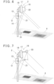
- FIG.6 shows a modification of the first embodiment.
- FIG.6 what are equivalent to components as shown in FIG.1 are referred by the same symbol, and the detailed description thereof will be omitted.
- a target plate 31 for distance calibration is provided at a necessary position of a pole 14.
- a distance between the target plate 31 and a reference position of a distance measurement camera 22 is actually measured or made known from a drawing, and the known distance is determined as an actually measured value.
- a reference numeral 4 denotes a projected unevenness map.
- the target plate 31 is measured before the fact, after the fact or simultaneously, a distance measurement result of the target plate 31 as obtained by the distance measurement camera 22 is compared with the actually measured value, and the distance measurement camera 22 is calibrated. Errors possessed by the distance measurement camera 22 are corrected by the calibration, and a measurement accuracy is improved.
- FIG.7 shows general features of a surveying system according to a second embodiment, and the surveying system is mainly constituted of a height measuring device 1 and a high-low measuring device 2. It is to be noted that, in FIG.7 , a reference numeral 4 denotes a projected unevenness map.
- FIG.7 what are equivalent to components as shown in FIG.1 are referred by the same symbol, and the detailed description thereof will be omitted. It is to be noted that a laser level planer 3 is not shown in FIG.7 .
- a distance measurement sensor 16 is constituted of a projector 17 and a camera 33.
- An optical axis of the projector 17 and an optical axis of the camera 33 are parallel, and both the optical axes are separated by a predetermined distance.
- the separation distance between the respective optical axes is known, and is a distance p by which a sufficient parallax is obtained to measure the floor surface. Therefore, the projector 17 and the camera 33 is a distance measurement sensor 16 which performs the distance measurement using the parallax.
- the projector 17 projects an image including a pattern 34 for the distance measurement ( FIG.8A ).
- FIG.8A shows a grid-like pattern, but it is sufficient that the pattern is capable of confirming a displacement due to the parallax, and the pattern may be a dot pattern in which dots are distributed vertically and horizontally at predetermined intervals.
- the pattern 34 projected onto the floor surface is picked up by the camera 33.
- an intersection (a black circle) in the pattern 34 is displaced to a position of a white circle. Since this displacement amount corresponds to a size of the unevenness, when obtaining a displacement amount of each intersection in the entire pattern 34, it is possible to measure an unevenness state based on the displacement amounts.
- an unevenness map 4 can be created.
- This unevenness map 4 may be projected on the pattern 34 so as to be superimposed (see FIG.8B ), or the unevenness map 4 alone may be projected.
- the distance measurement sensor 16 may be constituted of two cameras (a parallax camera) with a predetermined parallax.
- FIG.9 and FIG.12 show general features of a surveying system according to the third embodiment, and the surveying system is mainly constituted of a height measuring device 1 and a high-low measuring device 2 similarly to the first embodiment.
- an electro-optical distance device with a tracking function for instance, a total station 37 is used as the height measuring device 1.
- a tracking function for instance, the tracking based on images using an image sensor, the shape tracking using a laser scanner, or the like.
- FIG.9 what are equivalent to components as shown in FIG.1 are referred by same symbol, and the detailed description thereof will be omitted.
- the total station 37 is horizontally leveled and installed at a necessary position.
- the total station 37 is installed at a known height. That is, the total station 37 has a survey reference point and is installed so that three-dimensional coordinates of the survey reference point, or at least height coordinates (a height position) are known. For instance, by referring to FIG.12 , assuming that the total station 37 is installed on the floor surface 27 and the floor surface 27 has a survey reference height, a height D from the floor surface 27 to the survey reference point is known.
- a high-low measuring device 2 has a prism 35 with retroreflective characteristics as an object to be measured for the height measurement.
- An optical center of the prism 35 and a measurement reference position of the distance measurement camera 22 have a known relationship. It is to be noted that a reflective sheet may be used as the object.
- the total station 37 includes a telescope module (not shown) which sights the prism 35 as the object, projects a tracking light via the telescope module, and tracks the prism 35. Further, the total station 37 projects a distance measuring light via the telescope module, receives a reflected light from the prism 35, and performs the electro-optical distance measurement with respect to the prism 35.
- a telescope module not shown which sights the prism 35 as the object, projects a tracking light via the telescope module, and tracks the prism 35. Further, the total station 37 projects a distance measuring light via the telescope module, receives a reflected light from the prism 35, and performs the electro-optical distance measurement with respect to the prism 35.
- the total station 37 mainly includes an arithmetic control module 38, a TS communication module 42, a storage module 43, a distance measuring module 44, a tracking module 45, a horizontal angle detector 47, a vertical angle detector 48, a horizontal rotation driving module 49, a vertical rotation driving module 50, a display unit 51, and an operation module 52.
- the arithmetic control module 38 performs individually controlling the TS communication module 42, the distance measuring module 44, the tracking module 45, the horizontal rotation driving module 49, the vertical rotation driving module 50 and the display unit 51 such as driving control and synchronous control and integrally controlling these modules.
- the TS communication module 42 performs the data communication with the high-low measuring device 2, and the tracking module 45 projects a tracking light, receives a reflected light from the prism 35, and carries out the tracking. Further, in parallel with the tracking by the tracking module 45, the distance measuring module 44 projects a distance measuring light and receives the reflected light from the prism 35, and performs the distance measurement with the prism 35 as an object.
- the horizontal angle detector 47 has a reference point, and is configured to detect a horizontal angle of an optical axis of a telescope with respect to this reference point. Further, the vertical angle detector 48 is configured to detect a high-low angle with respect to the horizontality.
- the horizontal rotation driving module 49 and the vertical rotation driving module 50 horizontally rotate and vertically rotate the telescope so that the prism 35 is tracked.
- the horizontal angle detector 47 and the vertical angle detector 48 detect a horizontal angle and a vertical angle in the distance measurement. Therefore, an object is subjected to the distance measurement, and three-dimensional coordinates of the object are determined.
- the TS communication module 42 transmits the determined three-dimensional coordinates to the high-low measuring device 2 in real time.
- the ON/OFF of operations, settings of operation conditions of the total station 37, and the like are input from the operation module 52, and an operation state and the like of the total station 37 are displayed in the display unit 12.
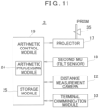
- FIG.11 shows general features of the high-low measuring device 2 of the third embodiment, the high-low measuring device 2 in the third embodiment and the high-low measuring device 2 in the first embodiment have substantially the same structure, the prism 35 is provided in place of the photodetector 15, and the high-low measuring device 2 includes a terminal communication module 53 for the data communication with the total station 37.
- a distance measurement camera 22 is shown as the distance measurement sensor 16, but the distance measurement sensor 16 may be constituted of the projector 17 and the camera 33, or a parallax camera as illustrated in the second embodiment.
- FIG.12 A description will be given on the unevenness measurement in the third embodiment by referring to FIG.12 . It is to be noted that, in FIG.12 , what are equivalent to components as shown in FIG.4 are referred by the same symbol, and the detailed description thereof will be omitted.
- the prism 35 is measured by the total station 37, and the total station 37 transmits three-dimensional coordinates of the prism 35 as the measurement data from the TS communication module 42 to the terminal communication module 53 of the high-low measuring device 2.
- the terminal communication module 53 inputs the received three-dimensional data to the arithmetic control module 19.
- the three-dimensional data is further input to the arithmetic processing module 24, and the arithmetic processing module 24 acquires a height of the prism 35 from the three-dimensional data, that is, a height of an irradiation position of the distance measuring light of the total station 37.
- the acquired height of the irradiation position of the distance measuring light is a height of the prism 35 (a height of the optical center of the prism 35) with reference to the floor surface 27 (see FIG.4 ).
- the arithmetic processing module 24 is capable of acquiring a height of the distance measurement camera 22 with reference to the floor surface 27 from a known relationship between the optical center of the prism 35 and the measurement reference position of the distance measurement camera 22 and from the height of the prism 35.
- an unevenness state of the construction surface 28b can be measured from the measurement result of the distance measurement camera 22.
- the creation of the unevenness map 4 and the projection of an unevenness map image onto the construction surface 28b are the same as the first embodiment, and hence a description thereof will be omitted.
- FIG.13A, FIG.13B and FIG.13C A description will be given on a fourth embodiment by referring to FIG.13A, FIG.13B and FIG.13C .
- a distance measurement sensor 16 is constituted of a laser length measuring device which projects a single beam (not shown) and an LED illuminator 55.
- An optical axis of the laser length measuring device is parallel or substantially parallel to that of the LED illuminator 55, and a distance between the optical axes is known.
- Illumination lights projected from the LED illuminator 55 are set as visible lights with different wavelengths (different colors). For instance, colors of the illumination lights as emitted from the LED illuminator are set to red, blue, and green.
- LED illuminators 55 of different colors may be provided with their optical axes aligned, alternatively, one LED illuminator 55 may be used, which is capable of projecting the illumination lights of a plurality of colors and of changing over colors of the illumination lights and then irradiating the illumination lights.
- the illumination light may have the necessary spread. For instance, a diameter may become 5 cm on an irradiated surface. It is to be noted that the spread of the illumination light may be appropriately changeable in correspondence with a work state, and the diameter is not limited to 5 cm.
- the LED illuminator 55 has a function as a projector, and the projector 17 is omitted in the fourth embodiment.
- the fourth embodiment illustrates a case where a laser level planer 3 is used as a height measuring device 1, but it is needless to say that the embodiment is possible even if a total station 37 is used.
- a photodetection sensor 21 of a photodetector 15 detects a horizontal reference plane O, and thereby, it is possible to acquire a height of a measurement reference position of the laser length measuring device, and an unevenness amount of a construction surface 28b (see FIG.4 ) can be measured from a measurement result of the laser length measuring device.
- An arithmetic control module 19 changes a color of illumination light from the LED illuminator 55 in correspondence with the unevenness amount and selects a color of the illumination light. By changing the color of the illumination light as irradiated on the construction surface 28b in correspondence with the unevenness amount, it is possible to visually confirm an unevenness state of a measuring position.
- a green illumination light G is irradiated ( FIG.13A ) in case of an appropriate range (for instance, ⁇ 3 mm with respect to a construction finished surface 28a (see FIG.4 ))
- a red illumination light R is irradiated ( FIG.13B ) in case of a convexity beyond the appropriate range
- a blue illumination light B is irradiated in case of a concavity beyond the appropriate range.
- the high-low measuring device 2 can be a handheld type without being installed on a construction floor surface 28.
- a height of the high-low measuring device 2 (that is, a height of a prism 35) is measured in real time by the total station 37, and a tilt of the high-low measuring device 2 (a tilt of the distance measurement sensor 16) is detected in real time by a second tilt sensor 18. Further, by correcting the measured height of the high-low measuring device 2 with the detected tilt, an accurate height of the distance measurement sensor 16 is obtained. Therefore, an accurate unevenness amount is determined from a measured value of the distance measurement sensor 16.
- the high-low measuring device 2 is a handheld type and the distance measurement sensor 16 includes the LED illuminator 55 as illustrated in the fourth embodiment
- the color of the illumination light changes in correspondence with the unevenness state. Therefore, by swinging the high-low measuring device 2 at a visible speed and within a visible range, it is possible to recognize the irradiation by the illumination light as the unevenness map.
- the high-low measuring device has casters for moving or is mounted on a moving vehicle, and thereby the high-low measuring device is capable of irradiating while being moved by remote controlling or a program.
- the case of measuring the unevenness on the object surface or the construction surface has been described above, it is needless to say that by measuring a deviation with respect to the object surface or to a set height of the construction surface (a construction finished surface), or by measuring a plurality of points on the construction surface, a tilt with respect to the horizontality can be measured.
Landscapes
- Engineering & Computer Science (AREA)
- Physics & Mathematics (AREA)
- General Physics & Mathematics (AREA)
- Radar, Positioning & Navigation (AREA)
- Remote Sensing (AREA)
- Computer Vision & Pattern Recognition (AREA)
- Theoretical Computer Science (AREA)
- Geometry (AREA)
- Quality & Reliability (AREA)
- Multimedia (AREA)
- Signal Processing (AREA)
- Length Measuring Devices By Optical Means (AREA)
Description
- The present disclosure relates to a surveying system which determines an unevenness state of an object surface.
- In a concrete placing work or a ground leveling work, it is required to eliminate an unevenness state (an irregularity state) of a placed surface or a leveled surface and to construct the placed surface or the leveled surface to a set height.
- Conventionally, for instance, in the concrete placing work, a measuring rod is inserted into a concrete at a placed part, and a height of the concrete of the placed part is actually measured at predetermined intervals.
- After actually measuring the thickness (the height), if an unevenness state occurs, correction work is performed that the concrete is added to concave portions, or the concrete is removed from convex portions, and so forth.
- In conventional methods, individual height measurements are done manually, which makes the workability of the unevenness measurement poor. Further, the concrete placing work, the height measuring work, and the correcting work are separate processes, which results in a poor work efficiency.
- Further, in the ground leveling work, a leveling height (the unevenness state) is measured, for instance, by stretching a string at a predetermined height after the ground leveling, and if any deviation or unevenness with respect to the set height is occurred, correction of filling or removing the soil is performed.
-
US 2021/214922 A1 discloses a display system for a work vehicle. - A camera captures an image of a surrounding environment of a work vehicle and a shape sensor measures a three-dimensional shape of the surrounding environment and outputs 3D shape data indicative of the three-dimensional shape. A controller generates display image data that represents a display image of the surrounding environment of the work vehicle.
- It is an object of the present disclosure to provide a surveying system which can easily measure a deviation of an object surface with respect to a set height or an unevenness state and enables the construction work, such as placing work of concrete or leveling work of ground in parallel with a measurement of a height of the set object surface or a measurement of the unevenness state.
- To attain the object as described above, a surveying system according to
claim 1 is provided. - Further, in the surveying system according to a preferred embodiment, the height measuring device is adapted to form a horizontal reference plane with a known height, the object is a photodetector for detecting the horizontal reference plane, and the arithmetic control module is configured to calculate a height of a measurement reference position of the distance measurement sensor with respect to the horizontal reference plane based on a detection result of the photodetector and to calculate the high-low information of the construction surface based on a measurement result of the distance measurement sensor.
- Further, in the surveying system according to a preferred embodiment, the height measuring device is a surveying instrument which is provided at a known height, has a TS communication module configured to transmit measurement results and has a tracking function, the high-low measuring device has a terminal communication module configured to receive measurement results from the TS communication module, the object is a prism, and the arithmetic control module is configured to acquire the height information of the prism via the terminal communication module, to calculate a height of the measurement reference position of the distance measurement sensor based on the height information of the prism, and to calculate the high-low information of the construction surface based on a measurement result of the distance measurement sensor.
- Further, in the surveying system according to a preferred embodiment, the high-low measuring device further comprises a tilt sensor, and the arithmetic control module is configured to correct the high-low information based on a detection result of the tilt sensor.
- Further, in the surveying system according to a preferred embodiment, the high-low measuring device further comprises a tilt sensor and is constituted as a handheld type, and the arithmetic control module is configured to correct the high-low information based on a detection result of the tilt sensor.
- Further, in the surveying system according to a preferred embodiment, the distance measurement sensor is a distance measurement camera.
- Further, in the surveying system according to a preferred embodiment, the distance measurement sensor is a parallax camera.
- Further, in the surveying system according to a preferred embodiment, the distance measurement sensor is constituted of a projector for projecting a pattern for measuring distance and a camera provided to produce a parallax with respect to the projector.
- Furthermore, in the surveying system according to a preferred embodiment, the distance measurement sensor is a laser length measuring device, and the distance measurement sensor irradiates laser beams of a plurality of different colors, and the arithmetic control module is configured to select a color of a laser beam in correspondence with the high-low information.
- According to the present disclosure, the surveying system comprises a height measuring device and a high-low measuring device, wherein the high-low measuring device comprises an object measured by the height measuring device, a distance measurement sensor which is provided in a known relationship with the object and measures a distance to a construction surface, a projecting device for projecting a high-low information, and an arithmetic control module, wherein the arithmetic control module is configured to calculate a high-low information of the construction surface based on a height information of the object measured by the height measuring device and a distance information measured by the distance measurement sensor, and wherein the projecting device is configured to project the high-low information onto the construction surface. As a result, an unevenness state of the object surface can be easily visually confirmed since the measurement information and the high-low information of that site are directly projected, which enables the construction work, such as the placement work or the ground leveling work in parallel with the measurement of the unevenness state.
-
-
FIG.1 is a schematic drawing of a surveying system according to a first embodiment. -
FIG.2 is a schematic block diagram of a laser level planer. -
FIG.3 is a schematic block diagram of a high-low measuring device. -
FIG.4 is an explanatory drawing regarding the measurement of an unevenness state. -
FIG.5 is a flowchart showing the unevenness measuring work. -
FIG.6 is a schematic drawing showing a modification of the first embodiment. -
FIG.7 is a schematic view of a surveying system according to a second embodiment. -
FIG.8A is a drawing showing an example of a pattern when performing a distance measurement using a parallax, andFIG.8B is a drawing of a projected image with an unevenness image superimposed on the pattern. -
FIG.9 is a schematic drawing of a surveying system according to a third embodiment. -
FIG.10 is a schematic block diagram of a total station in the third embodiment. -
FIG.11 is a schematic block diagram of a high-low measuring device in the third embodiment. -
FIG.12 is an explanatory drawing regarding the measurement of an unevenness state in the third embodiment. -
FIG.13A is a schematic drawing of a surveying system according to a fourth embodiment, andFIG.13B and FIG.13C are explanatory drawings of the measurement of an unevenness state. - Description will be given below on embodiments of the present disclosure by referring to attached drawings.
-
FIG.1 shows general features of a surveying system according to a first embodiment, and the surveying system is mainly constituted of aheight measuring device 1 and a high-low measuring device 2. It is to be noted that, inFIG.1 , areference numeral 4 denotes an unevenness map (to be described later). - In the first embodiment, a
laser level planer 3 is used as theheight measuring device 1. - The
laser level planer 3 forms a horizontal reference plane with a predetermined height by a laser beam. The horizontal reference plane may be formed by rotatably irradiating the laser beam on a horizontal plane or may be formed by horizontally irradiating a fan-shaped laser beam. In the following explanation, a case where a horizontal reference plane O is formed by rotatably irradiating the laser beam is described. - By referring to
FIG.2 , a description will be given on general features of thelaser level planer 3. - The
laser level planer 3 is installed at a necessary position via a support device such as a tripod. Thelaser level planer 3 mainly includes acontrol module 5, afirst tilt sensor 6, a laserbeam irradiation module 7, a leveling module 8, a horizontalrotation driving module 9, anoperation module 11, and adisplay unit 12. - The
first tilt sensor 6 detects a tilt of thelaser level planer 3 with respect to the horizontality, that is, a tilt of a laser beam as irradiated with respect to the horizontality. A detection result of thefirst tilt sensor 6 is input to thecontrol module 5. - The
control module 5 drives the leveling module 8 based on a detection result of thefirst tilt sensor 6, and adjusts thelaser level planer 3 to the horizontality. Thecontrol module 5 makes the laserbeam irradiation module 7 to irradiate the laser beam, makes the horizontalrotation driving module 9 to rotate the laserbeam irradiation module 7, and rotatably irradiates the laser beam such that the horizontal reference plane O is formed. - The
laser level planer 3 is installed so that the horizontal reference plane O is at a known height. For instance, a height of the horizontal reference plane O from a floor surface serving as a reference is known by actual measurements or based on specifications of thelaser level planer 3 and the like. When the known horizontal reference plane O is formed, the height of an object can be measured with reference to the horizontal reference plane O. - An instruction to turn ON/OFF operations of the
laser level planer 3, settings of operation conditions, and the like are input to thecontrol module 5 from theoperation module 11, and an operation state and the like are displayed on thedisplay unit 12. - By referring to
FIG.3 , a description will be given on the high-low measuring device 2. - The high-
low measuring device 2 includes apole 14, aphotodetector 15 as an object to be measured which is provided at a necessary height of thepole 14, adistance measurement sensor 16 provided at an upper end of thepole 14, aprojector 17 as a projecting device, asecond tilt sensor 18, and anarithmetic control module 19. Thephotodetector 15 and thedistance measurement sensor 16 are provided in a known positional relationship. - The
photodetector 15 has aphotodetection sensor 21 which extends in an up-and-down direction and has a predetermined length, and thephotodetection sensor 21 detects the laser beam and produces a detecting signal. Thephotodetection sensor 21 has a photodetection reference position (for instance, the center of the up-and-down direction of thephotodetection sensor 21 or a lower end of the photodetection sensor 21), and the photodetection reference position is a known position in the high-low measuring device 2. For instance, a distance between the photodetection reference position and the lower end of thepole 14 is known. - The detecting signal includes a photodetecting signal and a detecting position information. As the detecting position information, a deviation with respect to the photodetection reference position and the like are included. Therefore, based on the detecting signal, a height of the photodetection reference position with respect to the horizontal reference plane O is able to be measured. The detecting signal is input to the
arithmetic control module 19. - The
distance measurement sensor 16 is directed downward and measures a distance to the ground surface, and various kinds ofdistance measurement sensors 16 can be adopted. As an example, adistance measurement camera 22 is used as thedistance measurement sensor 16. Thedistance measurement camera 22 has an image pickup element consisting of many pixels, emits a distance measuring light for each pixel, receives a reflected light for each pixel, performs the distance measurement based on TOF (Time Of Flight) for each pixel, and planarly acquires the distance measurement data like an image. Alternatively, the distance measuring light may be scanned with a high-speed and the measurement may be planarly performed. The distance measurement data is input to thearithmetic control module 19. - The
distance measurement camera 22 has a measurement reference position, and a distance measured by thedistance measurement camera 22 is a distance from the measurement reference position. A distance between the measurement reference position and the lower end of thepole 14 is also known. Further, a relationship between the measurement reference position of thedistance measurement camera 22 and a photodetection reference position of thephotodetection sensor 21 is known, and a vertical distance between the measurement reference position and the photodetection reference position is also known. - Therefore, by measuring a height of the horizontal reference plane O by the
photodetection sensor 21, a height of the measurement reference position is acquired with respect to the horizontal reference plane O. - A relationship between the measurement reference position and a reference point of a projection optical system of the
projector 17 is known, and an optical axis of thedistance measurement camera 22 and an optical axis of theprojector 17 are parallel or substantially parallel, and a distance between both the optical axes is also known. - The
second tilt sensor 18 detects a tilt of thedistance measurement camera 22 with respect to the horizontality or a tilt of the optical axis of thedistance measurement camera 22 with respect to the verticality. Alternatively, a tilt of thepole 14 with respect to the verticality is detected. A tilt detection result of thesecond tilt sensor 18 is input to thearithmetic control module 19. - The optical axis of the
distance measurement camera 22 is set parallel to thepole 14. It is to be noted that, when thesecond tilt sensor 18 is configured to detect a tilt of thepole 14 with respect to the verticality, the optical axis of thedistance measurement camera 22 tilts with respect to thepole 14 at a known angle. - The
second tilt sensor 18 may be incorporated in thearithmetic control module 19. Further, as thesecond tilt sensor 18, various kinds of IMU sensors such as an acceleration sensor or a gyroscope sensor can be used. - The
arithmetic control module 19 includes anarithmetic processing module 24 and astorage module 25. As thearithmetic processing module 24, a CPU specialized to the present embodiment, a general-purpose CPU, an embedded CPU, a microprocessor, or the like is used. Further, as thestorage module 25, a semiconductor memory such as a RAM, a ROM, or a Flash ROM, or a DRAM, or a magnetic recording memory such as an HDD is used. - The
arithmetic processing module 24 develops various kinds of programs stored in thestorage module 25, and performs necessary processing and operations. - In the
storage module 25, various kinds of programs are stored to carry out the present embodiment. The programs include, for instance, a control program for integrally controlling the synchronization of thedistance measurement camera 22 and theprojector 17 or the like, a distance measurement program for making thedistance measurement camera 22 to perform the image pickup and the distance measurement, an arithmetic program for calculating the three-dimensional data based on the distance measurement data, a program for calculating a video signal based on the three-dimensional data, and the like. - Further, in the
storage module 25, a threshold value for determining a high-low state is stored, or a measurement result, the image data, and the like are stored. In the following description, the high-low state includes a state of a deviation with respect to a set height of an object surface to be measured, a state of irregularities (unevenness) with respect to a set plane, and a state of a tilt with respect to a horizontal plane. Further, the high-low information includes an information of a deviation with respect to a set height of an object surface, an information of unevenness with respect to a set plane, and an information of a state of a tilt with respect to a horizontal plane. - A description will be given by referring to
FIG.4 on a case where an unevenness state is measured. - In
FIG.4 , areference numeral 27 denotes a floor surface serving as a reference, and thelaser level planer 3 is installed at a known height with respect to thefloor surface 27 and forms a horizontal reference plane O of a known height with respect to thefloor surface 27. - Assuming that concrete is placed on a
construction floor surface 28 which is lowered from thefloor surface 27 by a predetermined amount and a construction finished surface is 28a. - For instance, a measurer butts the
pole 14 on theconstruction floor surface 28 and supports the high-low measuring device 2 vertically or substantially vertically. A vertical state of the high-low measuring device 2 is detected by thesecond tilt sensor 18. - The following description assumes that the high-
low measuring device 2 is vertically supported. - In the drawing, a reference sign O1 denotes a horizontal line running through a measurement reference position of the
distance measurement camera 22, and areference sign 02 denotes a horizontal line running through a photodetection reference position of thephotodetection sensor 21. The construction finishedsurface 28a is set to a height difference D with respect to the horizontal reference plane O such that a predetermined placing thickness can be obtained. - As described above, the measurement reference position and the photodetection reference position have the known relationship, and a distance between O1 and O2 has the known value d. Further, a deviation Δ between a laser beam receiving position of the
photodetection sensor 21 and the photodetection reference position (that is, a deviation Δ between the horizontal reference plane O and the photodetection reference position) is provided, and a distance measurement value S (that is, a distance between the measurement reference position of thedistance measurement camera 22 and aconstruction surface 28b) of the construction surface (a concrete placing surface) 28b as measured by thedistance measurement camera 22 is provided. - The unevenness ΔF of the
construction surface 28b with reference to the construction finishedsurface 28a is acquired by the following expression.
- Here, Δ is + above the photodetection reference position and - below the same. Further, as to the unevenness ΔF, a positive value indicates a state which is convex compared with the construction finished
surface 28a and a negative value indicates a state which is concave compared to the same. - The height difference D and the distance d between the measurement reference position and the photodetection reference position are set in the
arithmetic control module 19 in advance, and a distance measurement result of thedistance measurement camera 22 and a detecting signal of thephotodetection sensor 21 are input to thearithmetic control module 19, respectively. Thearithmetic control module 19 calculates the unevenness ΔF based on the height difference D, the distance d, the distance measurement result, and the detecting signal. - Further, the
distance measurement camera 22 is capable of performing the distance measurement in units of pixel of the image pickup element. Thearithmetic control module 19 calculates the unevenness ΔF in units of pixel and thereby acquires an unevenness ΔF distribution of an entire angle of field of thedistance measurement camera 22. - Further, the
arithmetic control module 19 classifies the unevenness ΔF with the use of a threshold value set in thestorage module 25, and can create anunevenness map 4. - For instance, in a case where the unevenness ΔF is + with respect to the construction finished
surface 28a, a warm color group is used, and the color density or the color tone is made darker for each 3 mm increase, for instance. Further, in a case where the unevenness ΔF is - with respect to the construction finishedsurface 28a, a cool color group is used, and the color density or the color tone is made darker for each 3 mm decrease, for instance. In theunevenness map 4 shown inFIG.1 , the unevenness state is indicated by the shading. - It is to be noted that the threshold value for classifying can be appropriately set to 5 mm or 1 cm, for instance, without being restricted to 3 mm. Further, the classifying may be indicated in one color and the shading only.
- The
arithmetic control module 19 inputs the created unevenness map to theprojector 17 as a video signal, and theunevenness map 4 is projected onto theconstruction surface 28b by theprojector 17. A position and a range of theunevenness map 4 to be projected coincide with a position and a distance measurement range as measured by thedistance measurement camera 22, and the unevenness information of theconstruction surface 28b is accurately displayed by theunevenness map 4. Further, a worker can visually confirm the unevenness state of theconstruction surface 28b from the projectedunevenness map 4. The projection of theunevenness map 4 may be continuous or may be blinked. - In a case where the unevenness map is projected onto the
construction surface 28b in the state while placing concrete, the worker can confirm in real time the unevenness state when the concrete is placed, and the unevenness state can be corrected in real time. Therefore, the concrete placing work can be performed while correcting the unevenness state. - Further, in a case where the unevenness map is projected onto the
construction surface 28b, which has already been concrete-placed, a finish state and a finish accuracy of theconstruction surface 28b can be confirmed. - In the above explanation, it is assumed that the high-
low measuring device 2 is supported vertically, but in reality, it can be considered that the high-low measuring device 2 tilts or shakes. The high-low measuring device 2 includes asecond tilt sensor 18, which detects a tilt of the high-low measuring device 2 (thepole 14 or an optical axis of the distance measurement camera 22) in real time, and a tilt detection result is input to thearithmetic control module 19 in real time. - The
arithmetic control module 19 corrects measurement results (a measured distance, a measured position) of thedistance measurement camera 22 in real time based on a distance from the lower end of thepole 14 to the measurement reference position and the tilt detection result. Therefore, even if the high-low measuring device 2 has tilted or shaken, the corrected unevenness map is projected, and the measurer can confirm the accurate high-low information. - Next, a description will be given on the unevenness measuring work by referring to
FIG.5 . - (Step 01) The height measuring device 1 (the
laser level planer 3 in the present embodiment) is installed at a predetermined position. After leveling, a height of a projected laser beam from a reference position (a position of thefloor surface 27 in the present embodiment) is made known by actually measuring, for instance. - (Step 02) The laser beam is rotatably irradiated, and the horizontal reference plane O is formed.
- (Step 03) The horizontal reference plane O is detected by the
photodetector 15. A height of the measurement reference position of the distance measurement sensor 16 (thedistance measurement camera 22 in the present embodiment) is acquired with respect to the horizontal reference plane O based on a photodetecting position of thephotodetection sensor 21. - (Step 04) A construction surface is measured by the
distance measurement sensor 16. - (Step 05) A tilt of the optical axis of the
distance measurement sensor 16 is detected by thesecond tilt sensor 18. - (Step 06) The measurement result of the
distance measurement sensor 16 is corrected based on the tilt detection result. - (Step 07) A height of the
construction surface 28b with respect to the horizontal reference plane O is obtained based on the measurement result as corrected (hereinafter, a corrected measurement result) and the height of the measurement reference position with respect to the horizontal reference plane O. - (Step 08) A difference in height between the construction finished
surface 28a as set in advance and theconstruction surface 28b is calculated, and the high-low information is acquired. - (Step 09) An unevenness map image is created based on the high-low information and threshold values as set in advance.
- (Step 10) Based on a positional relationship between the
distance measurement sensor 16 and theprojector 17, and on the corrected distance measurement result, a distance between theprojector 17 and a projection plane (theconstruction surface 28b) is calculated, and the unevenness map image is projected. - In case of changing a measuring position and continuing the measurement,
Step 02 to Step 10 are repeatedly performed. -
FIG.6 shows a modification of the first embodiment. - In
FIG.6 , what are equivalent to components as shown inFIG.1 are referred by the same symbol, and the detailed description thereof will be omitted. - At a necessary position of a
pole 14, atarget plate 31 for distance calibration is provided. A distance between thetarget plate 31 and a reference position of adistance measurement camera 22 is actually measured or made known from a drawing, and the known distance is determined as an actually measured value. InFIG.6 , areference numeral 4 denotes a projected unevenness map. - In case of measuring a floor surface (a construction finished
surface 28a, aconstruction surface 28b) with thedistance measurement camera 22, thetarget plate 31 is measured before the fact, after the fact or simultaneously, a distance measurement result of thetarget plate 31 as obtained by thedistance measurement camera 22 is compared with the actually measured value, and thedistance measurement camera 22 is calibrated. Errors possessed by thedistance measurement camera 22 are corrected by the calibration, and a measurement accuracy is improved. -
FIG.7 shows general features of a surveying system according to a second embodiment, and the surveying system is mainly constituted of aheight measuring device 1 and a high-low measuring device 2. It is to be noted that, inFIG.7 , areference numeral 4 denotes a projected unevenness map. - In
FIG.7 , what are equivalent to components as shown inFIG.1 are referred by the same symbol, and the detailed description thereof will be omitted. It is to be noted that alaser level planer 3 is not shown inFIG.7 . - In the second embodiment, a
distance measurement sensor 16 is constituted of aprojector 17 and acamera 33. - An optical axis of the
projector 17 and an optical axis of thecamera 33 are parallel, and both the optical axes are separated by a predetermined distance. The separation distance between the respective optical axes is known, and is a distance p by which a sufficient parallax is obtained to measure the floor surface. Therefore, theprojector 17 and thecamera 33 is adistance measurement sensor 16 which performs the distance measurement using the parallax. - At the time of the distance measurement of the floor surface, the
projector 17 projects an image including apattern 34 for the distance measurement (FIG.8A ). It is to be noted thatFIG.8A shows a grid-like pattern, but it is sufficient that the pattern is capable of confirming a displacement due to the parallax, and the pattern may be a dot pattern in which dots are distributed vertically and horizontally at predetermined intervals. - The
pattern 34 projected onto the floor surface is picked up by thecamera 33. - In an image acquired by the
camera 33, an intersection (a black circle) in thepattern 34 is displaced to a position of a white circle. Since this displacement amount corresponds to a size of the unevenness, when obtaining a displacement amount of each intersection in theentire pattern 34, it is possible to measure an unevenness state based on the displacement amounts. - Based on this unevenness state, like the above-described embodiment, an
unevenness map 4 can be created. Thisunevenness map 4 may be projected on thepattern 34 so as to be superimposed (seeFIG.8B ), or theunevenness map 4 alone may be projected. - Further, as a modification of the second embodiment, the
distance measurement sensor 16 may be constituted of two cameras (a parallax camera) with a predetermined parallax. - A description will be given on a third embodiment by referring to
FIG.9 to FIG.12 . -
FIG.9 andFIG.12 show general features of a surveying system according to the third embodiment, and the surveying system is mainly constituted of aheight measuring device 1 and a high-low measuring device 2 similarly to the first embodiment. - In the third embodiment, an electro-optical distance device with a tracking function, for instance, a
total station 37 is used as theheight measuring device 1. It is to be noted that, as other measuring devices with the tracking function, there are measuring devices with a tracking function, for instance, the tracking based on images using an image sensor, the shape tracking using a laser scanner, or the like. - It is to be noted that, in
FIG.9 , what are equivalent to components as shown inFIG.1 are referred by same symbol, and the detailed description thereof will be omitted. - The
total station 37 is horizontally leveled and installed at a necessary position. Thetotal station 37 is installed at a known height. That is, thetotal station 37 has a survey reference point and is installed so that three-dimensional coordinates of the survey reference point, or at least height coordinates (a height position) are known. For instance, by referring toFIG.12 , assuming that thetotal station 37 is installed on thefloor surface 27 and thefloor surface 27 has a survey reference height, a height D from thefloor surface 27 to the survey reference point is known. - A high-
low measuring device 2 has aprism 35 with retroreflective characteristics as an object to be measured for the height measurement. An optical center of theprism 35 and a measurement reference position of thedistance measurement camera 22 have a known relationship. It is to be noted that a reflective sheet may be used as the object. - The
total station 37 includes a telescope module (not shown) which sights theprism 35 as the object, projects a tracking light via the telescope module, and tracks theprism 35. Further, thetotal station 37 projects a distance measuring light via the telescope module, receives a reflected light from theprism 35, and performs the electro-optical distance measurement with respect to theprism 35. - By referring to
FIG.10 , a description will be given on an approximate arrangement of thetotal station 37. - The
total station 37 mainly includes anarithmetic control module 38, aTS communication module 42, astorage module 43, adistance measuring module 44, atracking module 45, ahorizontal angle detector 47, avertical angle detector 48, a horizontalrotation driving module 49, a verticalrotation driving module 50, adisplay unit 51, and anoperation module 52. - The
arithmetic control module 38 performs individually controlling theTS communication module 42, thedistance measuring module 44, thetracking module 45, the horizontalrotation driving module 49, the verticalrotation driving module 50 and thedisplay unit 51 such as driving control and synchronous control and integrally controlling these modules. - The
TS communication module 42 performs the data communication with the high-low measuring device 2, and thetracking module 45 projects a tracking light, receives a reflected light from theprism 35, and carries out the tracking. Further, in parallel with the tracking by thetracking module 45, thedistance measuring module 44 projects a distance measuring light and receives the reflected light from theprism 35, and performs the distance measurement with theprism 35 as an object. - Further, the
horizontal angle detector 47 has a reference point, and is configured to detect a horizontal angle of an optical axis of a telescope with respect to this reference point. Further, thevertical angle detector 48 is configured to detect a high-low angle with respect to the horizontality. - The horizontal
rotation driving module 49 and the verticalrotation driving module 50 horizontally rotate and vertically rotate the telescope so that theprism 35 is tracked. Thehorizontal angle detector 47 and thevertical angle detector 48 detect a horizontal angle and a vertical angle in the distance measurement. Therefore, an object is subjected to the distance measurement, and three-dimensional coordinates of the object are determined. - The
TS communication module 42 transmits the determined three-dimensional coordinates to the high-low measuring device 2 in real time. - The ON/OFF of operations, settings of operation conditions of the
total station 37, and the like are input from theoperation module 52, and an operation state and the like of thetotal station 37 are displayed in thedisplay unit 12. -
FIG.11 shows general features of the high-low measuring device 2 of the third embodiment, the high-low measuring device 2 in the third embodiment and the high-low measuring device 2 in the first embodiment have substantially the same structure, theprism 35 is provided in place of thephotodetector 15, and the high-low measuring device 2 includes aterminal communication module 53 for the data communication with thetotal station 37. - In
FIG.11 , adistance measurement camera 22 is shown as thedistance measurement sensor 16, but thedistance measurement sensor 16 may be constituted of theprojector 17 and thecamera 33, or a parallax camera as illustrated in the second embodiment. - A description will be given on the unevenness measurement in the third embodiment by referring to
FIG.12 . It is to be noted that, inFIG.12 , what are equivalent to components as shown inFIG.4 are referred by the same symbol, and the detailed description thereof will be omitted. - The
prism 35 is measured by thetotal station 37, and thetotal station 37 transmits three-dimensional coordinates of theprism 35 as the measurement data from theTS communication module 42 to theterminal communication module 53 of the high-low measuring device 2. Theterminal communication module 53 inputs the received three-dimensional data to thearithmetic control module 19. - The three-dimensional data is further input to the
arithmetic processing module 24, and thearithmetic processing module 24 acquires a height of theprism 35 from the three-dimensional data, that is, a height of an irradiation position of the distance measuring light of thetotal station 37. - The acquired height of the irradiation position of the distance measuring light is a height of the prism 35 (a height of the optical center of the prism 35) with reference to the floor surface 27 (see
FIG.4 ). - Further, the
arithmetic processing module 24 is capable of acquiring a height of thedistance measurement camera 22 with reference to thefloor surface 27 from a known relationship between the optical center of theprism 35 and the measurement reference position of thedistance measurement camera 22 and from the height of theprism 35. - Thus, an unevenness state of the
construction surface 28b can be measured from the measurement result of thedistance measurement camera 22. - The creation of the
unevenness map 4 and the projection of an unevenness map image onto theconstruction surface 28b are the same as the first embodiment, and hence a description thereof will be omitted. - A description will be given on a fourth embodiment by referring to
FIG.13A, FIG.13B and FIG.13C . - In the fourth embodiment, a
distance measurement sensor 16 is constituted of a laser length measuring device which projects a single beam (not shown) and anLED illuminator 55. An optical axis of the laser length measuring device is parallel or substantially parallel to that of theLED illuminator 55, and a distance between the optical axes is known. Illumination lights projected from theLED illuminator 55 are set as visible lights with different wavelengths (different colors). For instance, colors of the illumination lights as emitted from the LED illuminator are set to red, blue, and green. - It is to be noted that
several LED illuminators 55 of different colors may be provided with their optical axes aligned, alternatively, oneLED illuminator 55 may be used, which is capable of projecting the illumination lights of a plurality of colors and of changing over colors of the illumination lights and then irradiating the illumination lights. Further, in order to facilitate the visibility, the illumination light may have the necessary spread. For instance, a diameter may become 5 cm on an irradiated surface. It is to be noted that the spread of the illumination light may be appropriately changeable in correspondence with a work state, and the diameter is not limited to 5 cm. - The
LED illuminator 55 has a function as a projector, and theprojector 17 is omitted in the fourth embodiment. - The fourth embodiment illustrates a case where a
laser level planer 3 is used as aheight measuring device 1, but it is needless to say that the embodiment is possible even if atotal station 37 is used. - A
photodetection sensor 21 of aphotodetector 15 detects a horizontal reference plane O, and thereby, it is possible to acquire a height of a measurement reference position of the laser length measuring device, and an unevenness amount of aconstruction surface 28b (seeFIG.4 ) can be measured from a measurement result of the laser length measuring device. - An
arithmetic control module 19 changes a color of illumination light from theLED illuminator 55 in correspondence with the unevenness amount and selects a color of the illumination light. By changing the color of the illumination light as irradiated on theconstruction surface 28b in correspondence with the unevenness amount, it is possible to visually confirm an unevenness state of a measuring position. - For instance, a green illumination light G is irradiated (
FIG.13A ) in case of an appropriate range (for instance, ±3 mm with respect to a construction finishedsurface 28a (seeFIG.4 )), a red illumination light R is irradiated (FIG.13B ) in case of a convexity beyond the appropriate range, and a blue illumination light B (FIG.13C ) is irradiated in case of a concavity beyond the appropriate range. - It is to be noted that, with respect to the color of the illumination light to be irradiated, by mixing the illumination lights, a change of the color is obtained. Therefore, when the
arithmetic control module 19 controls the mixing of the illumination lights in correspondence with an unevenness amount, the finer unevenness state can be projected. - In a case where a
total station 37 is used as theheight measuring device 1 and a high-low measuring device 2 is tracked and measured by thetotal station 37, the high-low measuring device 2 can be a handheld type without being installed on aconstruction floor surface 28. - A height of the high-low measuring device 2 (that is, a height of a prism 35) is measured in real time by the
total station 37, and a tilt of the high-low measuring device 2 (a tilt of the distance measurement sensor 16) is detected in real time by asecond tilt sensor 18. Further, by correcting the measured height of the high-low measuring device 2 with the detected tilt, an accurate height of thedistance measurement sensor 16 is obtained. Therefore, an accurate unevenness amount is determined from a measured value of thedistance measurement sensor 16. - It is to be noted that, needless to say, with respect to the unevenness map to be projected, the unevenness map as corrected in real time is projected.
- Then, in a case where the high-
low measuring device 2 is a handheld type and thedistance measurement sensor 16 includes theLED illuminator 55 as illustrated in the fourth embodiment, when the illumination light is irradiated while swinging the high-low measuring device 2 within a necessary range, the color of the illumination light changes in correspondence with the unevenness state. Therefore, by swinging the high-low measuring device 2 at a visible speed and within a visible range, it is possible to recognize the irradiation by the illumination light as the unevenness map. - Further, the high-low measuring device has casters for moving or is mounted on a moving vehicle, and thereby the high-low measuring device is capable of irradiating while being moved by remote controlling or a program. Although the case of measuring the unevenness on the object surface or the construction surface has been described above, it is needless to say that by measuring a deviation with respect to the object surface or to a set height of the construction surface (a construction finished surface), or by measuring a plurality of points on the construction surface, a tilt with respect to the horizontality can be measured.
Claims (9)
- A surveying system comprising: a height measuring device (1) and a high-low measuring device (2) for measuring a high-low information of a construction surface,wherein said high-low measuring device comprises an object (15, 35) measured by said height measuring device,a distance measurement sensor (16) which is provided in a known relationship with said object and measures a distance to said construction surface,a projecting device (17) which has an optical axis parallel or substantially parallel to an optical axis of said distance measurement sensor wherein the distance between both the optical axes is known and projects said high-low information, and an arithmetic control module (19),wherein said high-low information includes an information of a deviation with respect to a set height of said construction surface, an information of unevenness with respect to a set plane, and an information of a state of a tilt with respect to a horizontal plane,wherein said arithmetic control module is configured to calculate said high-low information of said construction surface based on a height information of said object measured by said height measuring device, the distance to said construction surface measured by said distance measurement sensor and the known relationship between said object and said distance measurement sensor, and wherein said projecting device is configured to project said high-low information onto said construction surface.
- The surveying system according to claim 1, wherein said height measuring device (1) is adapted to form a horizontal reference plane with a known height, said object is a photodetector (15) for detecting said horizontal reference plane, and said arithmetic control module (19) is configured to calculate a height of a measurement reference position of said distance measurement sensor (16) with respect to said horizontal reference plane based on a detection result of said photodetector and to calculate the high-low information of said construction surface based on a measurement result of said distance measurement sensor.
- The surveying system according to claim 1, wherein said height measuring device (1) is a surveying instrument (37) which is provided at a known height, has a TS communication module (42) configured to transmit measurement results and has a tracking function, said high-low measuring device (2) has a terminal communication module (53) configured to receive measurement results from said TS communication module, said object is a prism (35), and said arithmetic control module (19) is configured to acquire the height information of said prism via said terminal communication module, to calculate a height of said measurement reference position of said distance measurement sensor (16) based on said height information of said prism, and to calculate the high-low information of said construction surface based on a measurement result of said distance measurement sensor.
- The surveying system according to any one of claims 1 to 3, wherein said high-low measuring device (2) further comprises a tilt sensor (18), and said arithmetic control module (19) is configured to correct said high-low information based on a detection result of said tilt sensor.
- The surveying system according to claim 3, wherein said high-low measuring device (2) further comprises a tilt sensor (18) and is constituted as a handheld type, and said arithmetic control module (19) is configured to correct said high-low information based on a detection result of said tilt sensor.
- The surveying system according to any one of claims 1 to 5, wherein said distance measurement sensor (16) is a distance measurement camera (22) which has an image pickup element consisting of many pixels, emits a distance measuring light for each pixel, receives a reflected light for each pixel and performs the distance measurement based on TOF (Time Of Flight) for each pixel.
- The surveying system according to any one of claims 1 to 5, wherein said distance measurement sensor (16) is a parallax camera constituted of two cameras with a predetermined parallax.
- The surveying system according to any one of claims 1 to 5, wherein said distance measurement sensor (16) is constituted of a projector (17) for projecting a pattern for measuring distance and a camera (33) provided to produce a parallax with respect to said projector.
- The surveying system according to any one of claims 1 to 5, wherein said distance measurement sensor (16) is a laser length measuring device, and said distance measurement sensor irradiates laser beams of a plurality of different colors, and said arithmetic control module (19) is configured to select a color of a laser beam in correspondence with the high-low information.
Applications Claiming Priority (1)
| Application Number | Priority Date | Filing Date | Title |
|---|---|---|---|
| JP2021160383A JP2023050332A (en) | 2021-09-30 | 2021-09-30 | surveying system |
Publications (2)
| Publication Number | Publication Date |
|---|---|
| EP4160144A1 EP4160144A1 (en) | 2023-04-05 |
| EP4160144B1 true EP4160144B1 (en) | 2024-08-07 |
Family
ID=83457399
Family Applications (1)
| Application Number | Title | Priority Date | Filing Date |
|---|---|---|---|
| EP22197653.3A Active EP4160144B1 (en) | 2021-09-30 | 2022-09-26 | Surveying system |
Country Status (3)
| Country | Link |
|---|---|
| US (1) | US20230097350A1 (en) |
| EP (1) | EP4160144B1 (en) |
| JP (3) | JP2023050332A (en) |
Families Citing this family (4)
| Publication number | Priority date | Publication date | Assignee | Title |
|---|---|---|---|---|
| CN112611395B (en) * | 2020-12-31 | 2022-07-08 | 美国西北仪器公司 | Method and system for calibrating a laser leveler |
| JP7731230B2 (en) * | 2021-07-14 | 2025-08-29 | 株式会社トプコン | Information projection system and information projection method |
| JP2024151268A (en) * | 2023-04-11 | 2024-10-24 | 株式会社トプコン | Surveying systems and methods |
| JP2024151269A (en) * | 2023-04-11 | 2024-10-24 | 株式会社トプコン | Surveying System |
Family Cites Families (23)
| Publication number | Priority date | Publication date | Assignee | Title |
|---|---|---|---|---|
| JP2000230253A (en) * | 1999-02-09 | 2000-08-22 | Kumagai Gumi Co Ltd | Earth removing method |
| JP4787435B2 (en) * | 2001-09-13 | 2011-10-05 | カヤバ システム マシナリー株式会社 | Tunnel excavator position measurement device |
| JP5020585B2 (en) * | 2006-09-27 | 2012-09-05 | 株式会社トプコン | Measuring system |
| JP2012189433A (en) * | 2011-03-10 | 2012-10-04 | Takenaka Komuten Co Ltd | Surface formation supporting system, surface formation supporting device, and surface formation supporting program |
| JP5796998B2 (en) * | 2011-04-28 | 2015-10-21 | 株式会社トプコン | Survey point indicating device and survey system |
| US9222771B2 (en) * | 2011-10-17 | 2015-12-29 | Kla-Tencor Corp. | Acquisition of information for a construction site |
| EP2602587A1 (en) * | 2011-12-06 | 2013-06-12 | Hexagon Technology Center GmbH | Method and device for determining 3D coordinates of an object |
| US9776320B2 (en) * | 2014-08-28 | 2017-10-03 | Kabushiki Kaisha Topcon | Measurement and installation data indicating apparatus and measurement and installation data indicating method |
| US20160275460A1 (en) * | 2015-03-17 | 2016-09-22 | ecoATM, Inc. | Systems and methods for inspecting mobile devices and other consumer electronic devices with a laser |
| JP6524527B2 (en) * | 2015-09-18 | 2019-06-05 | 清水建設株式会社 | Measurement system, measurement processing apparatus and measurement method |
| JP6647899B2 (en) * | 2016-02-09 | 2020-02-14 | 株式会社トプコン | Surveying device, method of using surveying device, and control system for construction machine |
| US10579746B2 (en) * | 2016-03-28 | 2020-03-03 | Jz Technologies, Llc | Method and apparatus for applying an architectural layout to a building construction surface |
| JP6764590B2 (en) * | 2016-06-07 | 2020-10-07 | 清水建設株式会社 | Construction management equipment and construction management method |
| EP3410063B1 (en) * | 2017-05-31 | 2020-10-14 | Leica Geosystems AG | Geodetic surveying with correction for instrument tilt |
| JP7232437B2 (en) * | 2018-02-19 | 2023-03-03 | 国立大学法人 東京大学 | WORK VEHICLE DISPLAY SYSTEM AND GENERATION METHOD |
| US11971483B2 (en) * | 2018-11-09 | 2024-04-30 | Black & Decker Inc. | Positional tracking system and method |
| EP3888351A4 (en) * | 2018-11-29 | 2022-07-20 | Ha, Hieu Thuan Charles | Projection device for displaying construction plans |
| JP7287793B2 (en) * | 2019-02-26 | 2023-06-06 | 株式会社トプコン | Target device and survey system |
| JP2020169921A (en) * | 2019-04-04 | 2020-10-15 | 株式会社トプコン | Surveying robot and surveying robot system |
| EP3734222B1 (en) * | 2019-05-02 | 2024-12-11 | Leica Geosystems AG | Coordinate measuring and/or stake out device |
| JP2020186944A (en) * | 2019-05-10 | 2020-11-19 | 三菱電機株式会社 | Position / orientation estimation device and position / orientation estimation method |
| EP3783385A1 (en) * | 2019-08-23 | 2021-02-24 | Leica Geosystems AG | Combined point cloud generation using a stationary laser scanner and a mobile scanner |
| CN117859074A (en) * | 2021-06-11 | 2024-04-09 | 网络无人机公司 | System and method for wireless communication of drone swarms |
-
2021
- 2021-09-30 JP JP2021160383A patent/JP2023050332A/en active Pending
-
2022
- 2022-09-22 US US17/950,221 patent/US20230097350A1/en active Pending
- 2022-09-26 EP EP22197653.3A patent/EP4160144B1/en active Active
-
2025
- 2025-08-25 JP JP2025139678A patent/JP7839346B2/en active Active
- 2025-08-25 JP JP2025139679A patent/JP2025166255A/en active Pending
Also Published As
| Publication number | Publication date |
|---|---|
| EP4160144A1 (en) | 2023-04-05 |
| JP7839346B2 (en) | 2026-04-01 |
| JP2025166255A (en) | 2025-11-05 |
| JP2023050332A (en) | 2023-04-11 |
| US20230097350A1 (en) | 2023-03-30 |
| JP2025169417A (en) | 2025-11-12 |
Similar Documents
| Publication | Publication Date | Title |
|---|---|---|
| EP4160144B1 (en) | Surveying system | |
| CN100580374C (en) | Laser measuring method and laser measuring system | |
| US8629905B2 (en) | Localization of a surveying instrument in relation to a ground mark | |
| US9354054B2 (en) | Surveying system | |
| US9776320B2 (en) | Measurement and installation data indicating apparatus and measurement and installation data indicating method | |
| US9279679B2 (en) | Construction machine control method and construction machine control system | |
| US11421989B2 (en) | Surveying instrument | |
| US11598637B2 (en) | Surveying instrument | |
| US12359915B2 (en) | Surveying instrument and surveying system | |
| US20200386546A1 (en) | Surveying Instrument | |
| US6611664B2 (en) | Stereo image photographing system | |
| KR102154984B1 (en) | System of air shooting and ediding image for making numerical map | |
| JP2018173388A (en) | Position measuring device and position measurement method | |
| WO2024202653A1 (en) | Survey system and measurement method | |
| EP2240741B1 (en) | Localizing a surveying instrument in relation to a ground mark | |
| KR101172873B1 (en) | 3d image photographing apparatus for tunnel surveying | |
| JPH07139942A (en) | Surveying equipment | |
| US20250383201A1 (en) | Surveying system and surveying method | |
| JP2024139154A (en) | Surveying system and method | |
| EP4696982A1 (en) | Surveying system | |
| WO2024214696A1 (en) | Survey system and measurement method | |
| CN114383580B (en) | Electronic surveying instrument | |
| JP2020020716A (en) | Monopole base and surveying system |
Legal Events
| Date | Code | Title | Description |
|---|---|---|---|
| PUAI | Public reference made under article 153(3) epc to a published international application that has entered the european phase |
Free format text: ORIGINAL CODE: 0009012 |
|
| STAA | Information on the status of an ep patent application or granted ep patent |
Free format text: STATUS: REQUEST FOR EXAMINATION WAS MADE |
|
| 17P | Request for examination filed |
Effective date: 20220926 |
|
| AK | Designated contracting states |
Kind code of ref document: A1 Designated state(s): AL AT BE BG CH CY CZ DE DK EE ES FI FR GB GR HR HU IE IS IT LI LT LU LV MC MK MT NL NO PL PT RO RS SE SI SK SM TR |
|
| RBV | Designated contracting states (corrected) |
Designated state(s): AL AT BE BG CH CY CZ DE DK EE ES FI FR GB GR HR HU IE IS IT LI LT LU LV MC MK MT NL NO PL PT RO RS SE SI SK SM TR |
|
| GRAP | Despatch of communication of intention to grant a patent |
Free format text: ORIGINAL CODE: EPIDOSNIGR1 |
|
| STAA | Information on the status of an ep patent application or granted ep patent |
Free format text: STATUS: GRANT OF PATENT IS INTENDED |
|
| INTG | Intention to grant announced |
Effective date: 20240404 |
|
| GRAS | Grant fee paid |
Free format text: ORIGINAL CODE: EPIDOSNIGR3 |
|
| GRAA | (expected) grant |
Free format text: ORIGINAL CODE: 0009210 |
|
| STAA | Information on the status of an ep patent application or granted ep patent |
Free format text: STATUS: THE PATENT HAS BEEN GRANTED |
|
| AK | Designated contracting states |
Kind code of ref document: B1 Designated state(s): AL AT BE BG CH CY CZ DE DK EE ES FI FR GB GR HR HU IE IS IT LI LT LU LV MC MK MT NL NO PL PT RO RS SE SI SK SM TR |
|
| REG | Reference to a national code |
Ref country code: GB Ref legal event code: FG4D |
|
| REG | Reference to a national code |
Ref country code: CH Ref legal event code: EP |
|
| REG | Reference to a national code |
Ref country code: IE Ref legal event code: FG4D |
|
| REG | Reference to a national code |
Ref country code: DE Ref legal event code: R096 Ref document number: 602022005134 Country of ref document: DE |
|
| REG | Reference to a national code |
Ref country code: LT Ref legal event code: MG9D |
|
| REG | Reference to a national code |
Ref country code: NL Ref legal event code: MP Effective date: 20240807 |
|
| PG25 | Lapsed in a contracting state [announced via postgrant information from national office to epo] |
Ref country code: NO Free format text: LAPSE BECAUSE OF FAILURE TO SUBMIT A TRANSLATION OF THE DESCRIPTION OR TO PAY THE FEE WITHIN THE PRESCRIBED TIME-LIMIT Effective date: 20241107 |
|
| REG | Reference to a national code |
Ref country code: AT Ref legal event code: MK05 Ref document number: 1711406 Country of ref document: AT Kind code of ref document: T Effective date: 20240807 |
|
| PG25 | Lapsed in a contracting state [announced via postgrant information from national office to epo] |
Ref country code: FI Free format text: LAPSE BECAUSE OF FAILURE TO SUBMIT A TRANSLATION OF THE DESCRIPTION OR TO PAY THE FEE WITHIN THE PRESCRIBED TIME-LIMIT Effective date: 20240807 Ref country code: NL Free format text: LAPSE BECAUSE OF FAILURE TO SUBMIT A TRANSLATION OF THE DESCRIPTION OR TO PAY THE FEE WITHIN THE PRESCRIBED TIME-LIMIT Effective date: 20240807 Ref country code: GR Free format text: LAPSE BECAUSE OF FAILURE TO SUBMIT A TRANSLATION OF THE DESCRIPTION OR TO PAY THE FEE WITHIN THE PRESCRIBED TIME-LIMIT Effective date: 20241108 Ref country code: PL Free format text: LAPSE BECAUSE OF FAILURE TO SUBMIT A TRANSLATION OF THE DESCRIPTION OR TO PAY THE FEE WITHIN THE PRESCRIBED TIME-LIMIT Effective date: 20240807 Ref country code: PT Free format text: LAPSE BECAUSE OF FAILURE TO SUBMIT A TRANSLATION OF THE DESCRIPTION OR TO PAY THE FEE WITHIN THE PRESCRIBED TIME-LIMIT Effective date: 20241209 |
|
| PG25 | Lapsed in a contracting state [announced via postgrant information from national office to epo] |
Ref country code: BG Free format text: LAPSE BECAUSE OF FAILURE TO SUBMIT A TRANSLATION OF THE DESCRIPTION OR TO PAY THE FEE WITHIN THE PRESCRIBED TIME-LIMIT Effective date: 20240807 |
|
| PG25 | Lapsed in a contracting state [announced via postgrant information from national office to epo] |
Ref country code: LV Free format text: LAPSE BECAUSE OF FAILURE TO SUBMIT A TRANSLATION OF THE DESCRIPTION OR TO PAY THE FEE WITHIN THE PRESCRIBED TIME-LIMIT Effective date: 20240807 |
|
| PG25 | Lapsed in a contracting state [announced via postgrant information from national office to epo] |
Ref country code: IS Free format text: LAPSE BECAUSE OF FAILURE TO SUBMIT A TRANSLATION OF THE DESCRIPTION OR TO PAY THE FEE WITHIN THE PRESCRIBED TIME-LIMIT Effective date: 20241207 Ref country code: AT Free format text: LAPSE BECAUSE OF FAILURE TO SUBMIT A TRANSLATION OF THE DESCRIPTION OR TO PAY THE FEE WITHIN THE PRESCRIBED TIME-LIMIT Effective date: 20240807 |
|
| PG25 | Lapsed in a contracting state [announced via postgrant information from national office to epo] |
Ref country code: HR Free format text: LAPSE BECAUSE OF FAILURE TO SUBMIT A TRANSLATION OF THE DESCRIPTION OR TO PAY THE FEE WITHIN THE PRESCRIBED TIME-LIMIT Effective date: 20240807 |
|
| PG25 | Lapsed in a contracting state [announced via postgrant information from national office to epo] |
Ref country code: RS Free format text: LAPSE BECAUSE OF FAILURE TO SUBMIT A TRANSLATION OF THE DESCRIPTION OR TO PAY THE FEE WITHIN THE PRESCRIBED TIME-LIMIT Effective date: 20241107 Ref country code: ES Free format text: LAPSE BECAUSE OF FAILURE TO SUBMIT A TRANSLATION OF THE DESCRIPTION OR TO PAY THE FEE WITHIN THE PRESCRIBED TIME-LIMIT Effective date: 20240807 |
|
| PG25 | Lapsed in a contracting state [announced via postgrant information from national office to epo] |
Ref country code: RS Free format text: LAPSE BECAUSE OF FAILURE TO SUBMIT A TRANSLATION OF THE DESCRIPTION OR TO PAY THE FEE WITHIN THE PRESCRIBED TIME-LIMIT Effective date: 20241107 Ref country code: PT Free format text: LAPSE BECAUSE OF FAILURE TO SUBMIT A TRANSLATION OF THE DESCRIPTION OR TO PAY THE FEE WITHIN THE PRESCRIBED TIME-LIMIT Effective date: 20241209 Ref country code: PL Free format text: LAPSE BECAUSE OF FAILURE TO SUBMIT A TRANSLATION OF THE DESCRIPTION OR TO PAY THE FEE WITHIN THE PRESCRIBED TIME-LIMIT Effective date: 20240807 Ref country code: NO Free format text: LAPSE BECAUSE OF FAILURE TO SUBMIT A TRANSLATION OF THE DESCRIPTION OR TO PAY THE FEE WITHIN THE PRESCRIBED TIME-LIMIT Effective date: 20241107 Ref country code: NL Free format text: LAPSE BECAUSE OF FAILURE TO SUBMIT A TRANSLATION OF THE DESCRIPTION OR TO PAY THE FEE WITHIN THE PRESCRIBED TIME-LIMIT Effective date: 20240807 Ref country code: LV Free format text: LAPSE BECAUSE OF FAILURE TO SUBMIT A TRANSLATION OF THE DESCRIPTION OR TO PAY THE FEE WITHIN THE PRESCRIBED TIME-LIMIT Effective date: 20240807 Ref country code: IS Free format text: LAPSE BECAUSE OF FAILURE TO SUBMIT A TRANSLATION OF THE DESCRIPTION OR TO PAY THE FEE WITHIN THE PRESCRIBED TIME-LIMIT Effective date: 20241207 Ref country code: HR Free format text: LAPSE BECAUSE OF FAILURE TO SUBMIT A TRANSLATION OF THE DESCRIPTION OR TO PAY THE FEE WITHIN THE PRESCRIBED TIME-LIMIT Effective date: 20240807 Ref country code: GR Free format text: LAPSE BECAUSE OF FAILURE TO SUBMIT A TRANSLATION OF THE DESCRIPTION OR TO PAY THE FEE WITHIN THE PRESCRIBED TIME-LIMIT Effective date: 20241108 Ref country code: FI Free format text: LAPSE BECAUSE OF FAILURE TO SUBMIT A TRANSLATION OF THE DESCRIPTION OR TO PAY THE FEE WITHIN THE PRESCRIBED TIME-LIMIT Effective date: 20240807 Ref country code: ES Free format text: LAPSE BECAUSE OF FAILURE TO SUBMIT A TRANSLATION OF THE DESCRIPTION OR TO PAY THE FEE WITHIN THE PRESCRIBED TIME-LIMIT Effective date: 20240807 Ref country code: BG Free format text: LAPSE BECAUSE OF FAILURE TO SUBMIT A TRANSLATION OF THE DESCRIPTION OR TO PAY THE FEE WITHIN THE PRESCRIBED TIME-LIMIT Effective date: 20240807 Ref country code: AT Free format text: LAPSE BECAUSE OF FAILURE TO SUBMIT A TRANSLATION OF THE DESCRIPTION OR TO PAY THE FEE WITHIN THE PRESCRIBED TIME-LIMIT Effective date: 20240807 |
|
| PG25 | Lapsed in a contracting state [announced via postgrant information from national office to epo] |
Ref country code: SM Free format text: LAPSE BECAUSE OF FAILURE TO SUBMIT A TRANSLATION OF THE DESCRIPTION OR TO PAY THE FEE WITHIN THE PRESCRIBED TIME-LIMIT Effective date: 20240807 Ref country code: DK Free format text: LAPSE BECAUSE OF FAILURE TO SUBMIT A TRANSLATION OF THE DESCRIPTION OR TO PAY THE FEE WITHIN THE PRESCRIBED TIME-LIMIT Effective date: 20240807 |
|
| PG25 | Lapsed in a contracting state [announced via postgrant information from national office to epo] |
Ref country code: EE Free format text: LAPSE BECAUSE OF FAILURE TO SUBMIT A TRANSLATION OF THE DESCRIPTION OR TO PAY THE FEE WITHIN THE PRESCRIBED TIME-LIMIT Effective date: 20240807 |
|
| PG25 | Lapsed in a contracting state [announced via postgrant information from national office to epo] |
Ref country code: CZ Free format text: LAPSE BECAUSE OF FAILURE TO SUBMIT A TRANSLATION OF THE DESCRIPTION OR TO PAY THE FEE WITHIN THE PRESCRIBED TIME-LIMIT Effective date: 20240807 |
|
| PG25 | Lapsed in a contracting state [announced via postgrant information from national office to epo] |
Ref country code: SK Free format text: LAPSE BECAUSE OF FAILURE TO SUBMIT A TRANSLATION OF THE DESCRIPTION OR TO PAY THE FEE WITHIN THE PRESCRIBED TIME-LIMIT Effective date: 20240807 |
|
| REG | Reference to a national code |
Ref country code: DE Ref legal event code: R097 Ref document number: 602022005134 Country of ref document: DE |
|
| PG25 | Lapsed in a contracting state [announced via postgrant information from national office to epo] |
Ref country code: LU Free format text: LAPSE BECAUSE OF NON-PAYMENT OF DUE FEES Effective date: 20240926 |
|
| PLBE | No opposition filed within time limit |
Free format text: ORIGINAL CODE: 0009261 |
|
| STAA | Information on the status of an ep patent application or granted ep patent |
Free format text: STATUS: NO OPPOSITION FILED WITHIN TIME LIMIT |
|
| PG25 | Lapsed in a contracting state [announced via postgrant information from national office to epo] |
Ref country code: MC Free format text: LAPSE BECAUSE OF FAILURE TO SUBMIT A TRANSLATION OF THE DESCRIPTION OR TO PAY THE FEE WITHIN THE PRESCRIBED TIME-LIMIT Effective date: 20240807 |
|
| REG | Reference to a national code |
Ref country code: BE Ref legal event code: MM Effective date: 20240930 |
|
| PG25 | Lapsed in a contracting state [announced via postgrant information from national office to epo] |
Ref country code: BE Free format text: LAPSE BECAUSE OF NON-PAYMENT OF DUE FEES Effective date: 20240930 |
|
| 26N | No opposition filed |
Effective date: 20250508 |
|
| PG25 | Lapsed in a contracting state [announced via postgrant information from national office to epo] |
Ref country code: FR Free format text: LAPSE BECAUSE OF NON-PAYMENT OF DUE FEES Effective date: 20241007 |
|
| PG25 | Lapsed in a contracting state [announced via postgrant information from national office to epo] |
Ref country code: IE Free format text: LAPSE BECAUSE OF NON-PAYMENT OF DUE FEES Effective date: 20240926 |
|
| PG25 | Lapsed in a contracting state [announced via postgrant information from national office to epo] |
Ref country code: SE Free format text: LAPSE BECAUSE OF FAILURE TO SUBMIT A TRANSLATION OF THE DESCRIPTION OR TO PAY THE FEE WITHIN THE PRESCRIBED TIME-LIMIT Effective date: 20240807 |
|
| REG | Reference to a national code |
Ref country code: CH Ref legal event code: U11 Free format text: ST27 STATUS EVENT CODE: U-0-0-U10-U11 (AS PROVIDED BY THE NATIONAL OFFICE) Effective date: 20251001 |
|
| PGFP | Annual fee paid to national office [announced via postgrant information from national office to epo] |
Ref country code: DE Payment date: 20250730 Year of fee payment: 4 |
|
| PG25 | Lapsed in a contracting state [announced via postgrant information from national office to epo] |
Ref country code: RO Free format text: LAPSE BECAUSE OF FAILURE TO SUBMIT A TRANSLATION OF THE DESCRIPTION OR TO PAY THE FEE WITHIN THE PRESCRIBED TIME-LIMIT Effective date: 20240807 |
|
| PGFP | Annual fee paid to national office [announced via postgrant information from national office to epo] |
Ref country code: CH Payment date: 20251001 Year of fee payment: 4 |
|
| PG25 | Lapsed in a contracting state [announced via postgrant information from national office to epo] |
Ref country code: IT Free format text: LAPSE BECAUSE OF FAILURE TO SUBMIT A TRANSLATION OF THE DESCRIPTION OR TO PAY THE FEE WITHIN THE PRESCRIBED TIME-LIMIT Effective date: 20240807 Ref country code: CY Free format text: LAPSE BECAUSE OF FAILURE TO SUBMIT A TRANSLATION OF THE DESCRIPTION OR TO PAY THE FEE WITHIN THE PRESCRIBED TIME-LIMIT; INVALID AB INITIO Effective date: 20220926 |
|
| PG25 | Lapsed in a contracting state [announced via postgrant information from national office to epo] |
Ref country code: HU Free format text: LAPSE BECAUSE OF FAILURE TO SUBMIT A TRANSLATION OF THE DESCRIPTION OR TO PAY THE FEE WITHIN THE PRESCRIBED TIME-LIMIT; INVALID AB INITIO Effective date: 20220926 |