EP4160107A1 - Refrigeration cycle device - Google Patents
Refrigeration cycle device Download PDFInfo
- Publication number
- EP4160107A1 EP4160107A1 EP20937397.6A EP20937397A EP4160107A1 EP 4160107 A1 EP4160107 A1 EP 4160107A1 EP 20937397 A EP20937397 A EP 20937397A EP 4160107 A1 EP4160107 A1 EP 4160107A1
- Authority
- EP
- European Patent Office
- Prior art keywords
- heat medium
- heat exchanger
- load device
- heat
- bypass valve
- Prior art date
- Legal status (The legal status is an assumption and is not a legal conclusion. Google has not performed a legal analysis and makes no representation as to the accuracy of the status listed.)
- Withdrawn
Links
Images


Classifications
-
- F—MECHANICAL ENGINEERING; LIGHTING; HEATING; WEAPONS; BLASTING
- F24—HEATING; RANGES; VENTILATING
- F24F—AIR-CONDITIONING; AIR-HUMIDIFICATION; VENTILATION; USE OF AIR CURRENTS FOR SCREENING
- F24F5/00—Air-conditioning systems or apparatus not covered by F24F1/00 or F24F3/00, e.g. using solar heat or combined with household units such as an oven or water heater
- F24F5/0007—Air-conditioning systems or apparatus not covered by F24F1/00 or F24F3/00, e.g. using solar heat or combined with household units such as an oven or water heater cooling apparatus specially adapted for use in air-conditioning
- F24F5/001—Compression cycle type
-
- F—MECHANICAL ENGINEERING; LIGHTING; HEATING; WEAPONS; BLASTING
- F24—HEATING; RANGES; VENTILATING
- F24F—AIR-CONDITIONING; AIR-HUMIDIFICATION; VENTILATION; USE OF AIR CURRENTS FOR SCREENING
- F24F11/00—Control or safety arrangements
- F24F11/70—Control systems characterised by their outputs; Constructional details thereof
- F24F11/80—Control systems characterised by their outputs; Constructional details thereof for controlling the temperature of the supplied air
- F24F11/83—Control systems characterised by their outputs; Constructional details thereof for controlling the temperature of the supplied air by controlling the supply of heat-exchange fluids to heat-exchangers
- F24F11/84—Control systems characterised by their outputs; Constructional details thereof for controlling the temperature of the supplied air by controlling the supply of heat-exchange fluids to heat-exchangers using valves
-
- F—MECHANICAL ENGINEERING; LIGHTING; HEATING; WEAPONS; BLASTING
- F24—HEATING; RANGES; VENTILATING
- F24F—AIR-CONDITIONING; AIR-HUMIDIFICATION; VENTILATION; USE OF AIR CURRENTS FOR SCREENING
- F24F11/00—Control or safety arrangements
- F24F11/62—Control or safety arrangements characterised by the type of control or by internal processing, e.g. using fuzzy logic, adaptive control or estimation of values
- F24F11/63—Electronic processing
- F24F11/65—Electronic processing for selecting an operating mode
-
- F—MECHANICAL ENGINEERING; LIGHTING; HEATING; WEAPONS; BLASTING
- F25—REFRIGERATION OR COOLING; COMBINED HEATING AND REFRIGERATION SYSTEMS; HEAT PUMP SYSTEMS; MANUFACTURE OR STORAGE OF ICE; LIQUEFACTION SOLIDIFICATION OF GASES
- F25B—REFRIGERATION MACHINES, PLANTS OR SYSTEMS; COMBINED HEATING AND REFRIGERATION SYSTEMS; HEAT PUMP SYSTEMS
- F25B13/00—Compression machines, plants or systems, with reversible cycle
-
- F—MECHANICAL ENGINEERING; LIGHTING; HEATING; WEAPONS; BLASTING
- F25—REFRIGERATION OR COOLING; COMBINED HEATING AND REFRIGERATION SYSTEMS; HEAT PUMP SYSTEMS; MANUFACTURE OR STORAGE OF ICE; LIQUEFACTION SOLIDIFICATION OF GASES
- F25B—REFRIGERATION MACHINES, PLANTS OR SYSTEMS; COMBINED HEATING AND REFRIGERATION SYSTEMS; HEAT PUMP SYSTEMS
- F25B25/00—Machines, plants or systems, using a combination of modes of operation covered by two or more of the groups F25B1/00 - F25B23/00
- F25B25/005—Machines, plants or systems, using a combination of modes of operation covered by two or more of the groups F25B1/00 - F25B23/00 using primary and secondary systems
-
- F—MECHANICAL ENGINEERING; LIGHTING; HEATING; WEAPONS; BLASTING
- F25—REFRIGERATION OR COOLING; COMBINED HEATING AND REFRIGERATION SYSTEMS; HEAT PUMP SYSTEMS; MANUFACTURE OR STORAGE OF ICE; LIQUEFACTION SOLIDIFICATION OF GASES
- F25B—REFRIGERATION MACHINES, PLANTS OR SYSTEMS; COMBINED HEATING AND REFRIGERATION SYSTEMS; HEAT PUMP SYSTEMS
- F25B41/00—Fluid-circulation arrangements
- F25B41/20—Disposition of valves, e.g. of on-off valves or flow control valves
-
- F—MECHANICAL ENGINEERING; LIGHTING; HEATING; WEAPONS; BLASTING
- F25—REFRIGERATION OR COOLING; COMBINED HEATING AND REFRIGERATION SYSTEMS; HEAT PUMP SYSTEMS; MANUFACTURE OR STORAGE OF ICE; LIQUEFACTION SOLIDIFICATION OF GASES
- F25B—REFRIGERATION MACHINES, PLANTS OR SYSTEMS; COMBINED HEATING AND REFRIGERATION SYSTEMS; HEAT PUMP SYSTEMS
- F25B49/00—Arrangement or mounting of control or safety devices
- F25B49/02—Arrangement or mounting of control or safety devices for compression type machines, plants or systems
-
- F—MECHANICAL ENGINEERING; LIGHTING; HEATING; WEAPONS; BLASTING
- F24—HEATING; RANGES; VENTILATING
- F24F—AIR-CONDITIONING; AIR-HUMIDIFICATION; VENTILATION; USE OF AIR CURRENTS FOR SCREENING
- F24F2110/00—Control inputs relating to air properties
- F24F2110/10—Temperature
- F24F2110/12—Temperature of the outside air
-
- F—MECHANICAL ENGINEERING; LIGHTING; HEATING; WEAPONS; BLASTING
- F24—HEATING; RANGES; VENTILATING
- F24F—AIR-CONDITIONING; AIR-HUMIDIFICATION; VENTILATION; USE OF AIR CURRENTS FOR SCREENING
- F24F2140/00—Control inputs relating to system states
- F24F2140/20—Heat-exchange fluid temperature
-
- F—MECHANICAL ENGINEERING; LIGHTING; HEATING; WEAPONS; BLASTING
- F25—REFRIGERATION OR COOLING; COMBINED HEATING AND REFRIGERATION SYSTEMS; HEAT PUMP SYSTEMS; MANUFACTURE OR STORAGE OF ICE; LIQUEFACTION SOLIDIFICATION OF GASES
- F25B—REFRIGERATION MACHINES, PLANTS OR SYSTEMS; COMBINED HEATING AND REFRIGERATION SYSTEMS; HEAT PUMP SYSTEMS
- F25B2313/00—Compression machines, plants or systems with reversible cycle not otherwise provided for
- F25B2313/003—Indoor unit with water as a heat sink or heat source
-
- F—MECHANICAL ENGINEERING; LIGHTING; HEATING; WEAPONS; BLASTING
- F25—REFRIGERATION OR COOLING; COMBINED HEATING AND REFRIGERATION SYSTEMS; HEAT PUMP SYSTEMS; MANUFACTURE OR STORAGE OF ICE; LIQUEFACTION SOLIDIFICATION OF GASES
- F25B—REFRIGERATION MACHINES, PLANTS OR SYSTEMS; COMBINED HEATING AND REFRIGERATION SYSTEMS; HEAT PUMP SYSTEMS
- F25B2313/00—Compression machines, plants or systems with reversible cycle not otherwise provided for
- F25B2313/027—Compression machines, plants or systems with reversible cycle not otherwise provided for characterised by the reversing means
- F25B2313/02741—Compression machines, plants or systems with reversible cycle not otherwise provided for characterised by the reversing means using one four-way valve
-
- Y—GENERAL TAGGING OF NEW TECHNOLOGICAL DEVELOPMENTS; GENERAL TAGGING OF CROSS-SECTIONAL TECHNOLOGIES SPANNING OVER SEVERAL SECTIONS OF THE IPC; TECHNICAL SUBJECTS COVERED BY FORMER USPC CROSS-REFERENCE ART COLLECTIONS [XRACs] AND DIGESTS
- Y02—TECHNOLOGIES OR APPLICATIONS FOR MITIGATION OR ADAPTATION AGAINST CLIMATE CHANGE
- Y02B—CLIMATE CHANGE MITIGATION TECHNOLOGIES RELATED TO BUILDINGS, e.g. HOUSING, HOUSE APPLIANCES OR RELATED END-USER APPLICATIONS
- Y02B30/00—Energy efficient heating, ventilation or air conditioning [HVAC]
- Y02B30/54—Free-cooling systems
Definitions
- the present disclosure relates to a refrigeration cycle apparatus.
- PTL 1 below discloses an air-conditioning operation method using free cooling.
- a low-temperature cold water tank and a high-temperature cold water tank are provided, and in an intermediate period, low-temperature cold water produced by a refrigerator is supplied to the low-temperature cold water tank for latent heat treatment, and high-temperature cold water produced by a cooling tower is supplied to the high-temperature cold water tank for sensible heat treatment.
- high-temperature cold water in the high-temperature cold water tank is produced using low-temperature cold water produced by the refrigerator or low-temperature cold water produced by the cooling tower.
- the conventional technology described above requires two water tanks and requires two pumps for supplying water between each water tank and a load, which causes a problem of high cost.
- An object of present disclosure which has been made in order to solve the above problem, is to provide a refrigeration cycle apparatus that has a simple structure and is advantageous in increasing opportunities to utilize free cooling.
- a refrigeration cycle apparatus includes: a compressor to compress refrigerant; a first heat exchanger to cool the refrigerant compressed by the compressor with outdoor air; a decompressor to reduce a pressure of the refrigerant; a second heat exchanger to cool a heat medium with the refrigerant decompressed by the decompressor; a third heat exchanger to cool the heat medium with the outdoor air; a first heat medium passage connecting a heat medium outlet of the third heat exchanger to a heat medium inlet of the second heat exchanger; a first bypass valve to allow the heat medium to flow from the first heat medium passage into a first load device; a second heat medium passage to allow the heat medium flowing out of the second heat exchanger to flow into a second load device; a second bypass valve to allow the heat medium flowing out of the second heat exchanger to flow into the first load device; a return passage through which the heat medium returning from the first load device and the heat medium returning from the second load device pass; and a flow path switching valve to switch between a first
- Fig. 1 is a diagram illustrating a refrigeration cycle apparatus 1 according to a first embodiment.
- a refrigeration cycle apparatus 1 is provided with: a compressor 2 configured to compress refrigerant; a first heat exchanger 3 configured to cool the refrigerant compressed by the compressor 2 with outdoor air; a decompressor 4 configured to reduce a pressure of the refrigerant; a second heat exchanger 5 configured to cool a heat medium with the refrigerant decompressed by the decompressor 4; a third heat exchanger 6 configured to cool the heat medium with the outdoor air; a first heat medium passage 7 connecting a heat medium outlet of the third heat exchanger 6 to a heat medium inlet of the second heat exchanger 5; a first bypass valve 8 configured to allow the heat medium to flow from the first heat medium passage 7 into a first load device 100; a second heat medium passage 9 configured to allow the heat medium flowing out of the second heat exchanger 5 to flow into a second load device 200; a second bypass valve 10 configured to allow the heat medium
- a substance used as the refrigerant in the present disclosure is not particularly limited but may be, for example, any of CO2, HFC, HFO, and hydrocarbon.
- a substance used as the heat medium in the present disclosure is typically liquid water.
- a liquid except for water such as an aqueous solution of calcium chloride, an aqueous solution of ethylene glycol, an aqueous solution of propylene glycol, or alcohol, may be used as the heat medium.
- a heat medium pump 13 for circulating the heat medium is provided in the return passage 11.
- the first heat exchanger 3 is configured to cool the heat medium by heat exchange using outdoor air.
- the first heat exchanger 3 may be configured to directly exchange heat between the outdoor air and the heat medium in a closed type cooling tower.
- the first heat exchanger 3 may be configured to exchange heat between cooling water cooled by outdoor air in an open type cooling tower and the heat medium.
- the third heat exchanger 6 is configured to cool the heat medium by heat exchange using outdoor air.
- the third heat exchanger 6 may be configured to directly exchange heat between the outdoor air and the heat medium in the closed type cooling tower.
- the third heat exchanger 6 may be configured to exchange heat between the cooling water cooled by outdoor air in the open type cooling tower and the heat medium.
- the first heat exchanger 3 and the third heat exchanger 6 are disposed adjacent to each other.
- a blower 14 for feeding outdoor air to the first heat exchanger 3 and the third heat exchanger 6 is provided.
- the blower 14 may not be provided.
- the third heat exchanger 6 may be disposed at a position away from the first heat exchanger 3. In this case, a blower for feeding outdoor air to the first heat exchanger 3 and a blower for feeding outdoor air to the third heat exchanger 6 may be provided separately.
- first load device 100 and the second load device 200 are configured to perform air conditioning in a room by using a heat medium.
- the present disclosure is not limited to a system for performing air conditioning.
- one or both of the first load device 100 and the second load device 200 may be configured to cool a production apparatus by using a heat medium.
- the first load device 100 may include a heat exchanger for exchanging heat between the indoor air and the heat medium.
- the first load device 100 may be formed of, for example, a fan coil unit.
- the first load device 100 may be configured to mainly handle a sensible heat load in air conditioning. That is, the first load device 100 may be configured to mainly lower the temperature of the indoor air.
- the air flowing into the room from outside is hereinafter referred to as "ventilation air".
- the second load device 200 may include a heat exchanger for exchanging heat between the ventilation air and the heat medium.
- the second load device 200 may be formed of what is generally called an outside air processing air conditioner.
- the second load device 200 may be configured to mainly handle latent heat load in air conditioning. That is, in order to reduce humidity, the second load device 200 may be configured to mainly cool air to condense water vapor.
- Fig. 1 illustrates a state in which the refrigeration cycle apparatus 1 is being operated in a chiller independent operation mode.
- the heat medium is cooled by operating the compressor 2 without performing free cooling by the third heat exchanger 6.
- the refrigeration cycle apparatus 1 in the chiller independent operation mode operates as follows.
- the high-temperature and high-pressure refrigerant compressed by the compressor 2 flows into the first heat exchanger 3.
- the refrigerant cooled by the outdoor air in the first heat exchanger 3 is decompressed when passing through the decompressor 4.
- the first bypass valve 8 is closed.
- the second bypass valve 10 is open.
- the flow path switching valve 12 is in the first mode.
- the heat medium is cooled by exchanging heat between the low-temperature and low-pressure refrigerant flowing out of the decompressor 4 and the heat medium.
- a part of the heat medium flowing out of the second heat exchanger 5 is supplied to the first load device 100 through the second bypass valve 10.
- the remainder of the heat medium flowing out of the second heat exchanger 5 is supplied to the second load device 200 through the second heat medium passage 9.
- the heat medium returned from the first load device 100 and the heat medium returned from the second load device 200 merge and flow through the return passage 11.
- the heat medium flows from the return passage 11 into the first heat medium passage 7 without passing through the third heat exchanger 6.
- the entire amount of the heat medium flowing into the first heat medium passage 7 flows into the second heat exchanger 5.
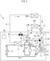
- Fig. 2 is a diagram illustrating a state in which the refrigeration cycle apparatus 1 is being operated in the free-cooling combined operation mode.
- the refrigeration cycle apparatus 1 in the free-cooling combined operation mode operates as follows.
- the refrigerant circulates through the same path as in the chiller independent operation mode.
- the first bypass valve 8 is open.
- the second bypass valve 10 is closed.
- the flow path switching valve 12 is in the second mode.
- the heat medium returned from the first load device 100 and the heat medium returned from the second load device 200 merge and flow through the return passage 11.
- the heat medium having passed through the return passage 11 flows into the third heat exchanger 6.
- the heat medium cooled by the outdoor air in the third heat exchanger 6 flows into the first heat medium passage 7.
- a part of the heat medium flowing through the first heat medium passage 7 is supplied to the first load device 100 through the first bypass valve 8.
- the remainder of the heat medium flowing through the first heat medium passage 7 flows into the second heat exchanger 5.
- the heat medium cooled by the refrigerant in the second heat exchanger 5 is supplied to the second load device 200 through the second heat medium passage 9.
- the temperature of the heat medium flowing from the second heat exchanger 5 into the second load device 200 needs to be made lower than the dew point temperature.
- the flow rate of the heat medium flowing through the second heat exchanger 5 in the free-cooling combined operation mode is smaller than that in the chiller independent operation mode. Therefore, in the free-cooling combined operation mode, the power consumption of the compressor 2 can be reduced as compared with the chiller independent operation mode, and energy saving can be achieved.
- the heat medium cooled by the free cooling of the third heat exchanger 6 flows into the first load device 100.
- the temperature of the heat medium cooled by free cooling varies in accordance with the outside air temperature.
- the temperature of the heat medium flowing into the first load device 100 which treats sensible heat, can be higher than the dew point temperature.
- the heat medium cooled by free cooling can be supplied to the first load device 100, and the heat medium further cooled by the second heat exchanger 5 to a temperature lower than the dew point temperature can be supplied to the second load device 200. Therefore, in the refrigeration cycle apparatus 1 of the present embodiment, free cooling can be utilized even when the temperature of the heat medium cooled by free cooling is higher than the dew point temperature.
- the simple configuration can be achieved by not requiring a tank that separately stores the heat medium cooled by free cooling and the heat medium further cooled by the second heat exchanger 5.
- the simple configuration can be achieved by the common heat medium pump 13 circulating both the heat medium cooled by free cooling and the heat medium further cooled by the second heat exchanger 5.
- the second bypass valve 10 may be slightly opened. Thereby, the heat medium having passed through the second bypass valve 10 mixes with the heat medium passing through the first bypass valve 8, so that the temperature of the heat medium flowing into the first load device 100 can be lowered.
- the refrigeration cycle apparatus 1 may further include control circuitry 50 configured to control the operation of the first bypass valve 8, the operation of the second bypass valve 10, and the operation of the flow path switching valve 12.
- control circuitry 50 configured to control the operation of the first bypass valve 8, the operation of the second bypass valve 10, and the operation of the flow path switching valve 12.
- the control circuitry 50 may be configured to close the first bypass valve 8 and open the second bypass valve 10 when the flow path switching valve 12 is in the first mode. This can automate the operation of the chiller independent operation mode.
- the control circuitry 50 may be configured to perform a process of opening the first bypass valve 8 and a process of closing the second bypass valve 10 when the flow path switching valve 12 is in the second mode.
- the control circuitry 50 may be configured to perform, when the flow path switching valve 12 is in the second mode, a process of opening the first bypass valve 8 and a process of making the opening degree of the second bypass valve 10 smaller than the opening degree when the flow path switching valve 12 is in the first mode.
- the refrigeration cycle apparatus 1 may be operated in a free-cooling independent operation mode in which the heat medium is cooled only by free cooling without operating the compressor 2.
- the free-cooling independent operation mode the compressor 2 is stopped, the flow path switching valve 12 is set to the second mode, the first bypass valve 8 is opened, and the second bypass valve 10 is fully closed.
- the control circuitry 50 may be configured to vary the operating speed of the compressor 2 by, for example, inverter control to adjust the capability of cooling the heat medium.
- the control circuitry 50 may be configured to further control at least one of the operation of the decompressor 4, the operation of the heat medium pump 13, and the operation of the blower 14.
- the decompressor 4 may be an expansion valve with an adjustable opening degree.
- the control circuitry 50 may be configured to vary the operating speed of the heat medium pump 13 by, for example, inverter control, thus adjusting the circulating flow rate of the heat medium.
- the control circuitry 50 may be configured to vary the operating speed of the blower 14 by, for example, inverter control, thus adjusting the air flow rate.
- the control circuitry 50 may control at least one of the operating speed of the compressor 2, the circulating flow rate of the heat medium, the opening degree of the decompressor 4, and the operating speed of the blower 14 so that each of the first load device 100 and the second load device 200 satisfies the required capability.
- the refrigeration cycle apparatus 1 may further include an outside air temperature sensor 15 for detecting the outside air temperature and a return temperature sensor 16 for detecting the return temperature.
- the control circuitry 50 may switch the flow path switching valve 12 from the first mode to the second mode when the outside air temperature is lower than the return temperature, and the difference between the return temperature and the outside air temperature is larger than a reference. That is, the control circuitry 50 may be configured to shift from the chiller independent operation mode to the free-cooling combined operation mode when the outside air temperature is lower than the return temperature, and the difference between the return temperature and the outside air temperature is larger than the above reference. This increases the opportunity to use the free-cooling combined operation mode instead of the chiller independent operation mode, thereby saving energy.
- the refrigeration cycle apparatus 1 may further include a capability shortage detector for detecting the shortage of the supplied cooling capability.
- the control circuitry 50 may have the function of the capability shortage detector.
- the capability shortage detector may determine whether the supplied cooling capability is sufficient for the sensible heat capability, which is the cooling capability required by the first load device 100, and the latent heat capability, which is the cooling capability required by the second load device 200.
- the capability shortage detector may detect the shortage of the supplied cooling capability based on information obtained from an indoor sensor (not illustrated) that detects the temperature and humidity of the indoor air.
- the capability shortage detector may detect the shortage of the supplied cooling capability based on the difference between an actual indoor temperature and a target value and the difference between an actual indoor humidity and a target value.
- the control circuitry 50 may reduce the opening degree of the first bypass valve 8 and increase the opening degree of the second bypass valve 10. That is, the control circuitry 50 may be configured to lower the opening degree of the first bypass valve 8 and to increase the opening degree of the second bypass valve 10 when the supplied cooling capability becomes insufficient during the execution of the free-cooling combined operation mode.
- the opening degree of the first bypass valve 8 decreases and that of the second bypass valve 10 increases, the flow rate of the heat medium flowing into the second heat exchanger 5 and cooled by the refrigerant increases, so that the supplied cooling capability increases. As a result, the shortage of supplied cooling capability is solved.
- control circuitry 50 may shift to the free-cooling independent operation mode in response to the difference between the return temperature and the outside air temperature.
- control circuitry 50 may shift to the free-cooling independent operation mode in response to the fact that the supplied cooling capability is sufficient.
- the refrigeration cycle apparatus 1 of the present embodiment will be further described below.
- the inlet of the first bypass valve 8 is connected to a branch portion 17 provided in the first heat medium passage 7.
- the outlet of the first bypass valve 8 is connected to the heat medium inlet of the first load device 100 by a heat medium passage 18.
- the second heat medium passage 9 connects the heat medium outlet of the second heat exchanger 5 to the heat medium inlet of the second load device 200.
- the inlet of the second bypass valve 10 is connected to a branch portion 19 provided in the second heat medium passage 9.
- the outlet of the second bypass valve 10 is connected to a branch portion 20 provided in the heat medium passage 18.
- the upstream portion of the return passage 11 is connected to both the heat medium outlet of the first load device 100 and the heat medium outlet of the second load device 200.
- the flow path switching valve 12 corresponds to a three-way valve having an inlet 12a, a first outlet 12b, and a second outlet 12c.
- the inlet 12a is connected to the downstream portion of the return passage 11.
- the first outlet 12b is connected to a branch portion 21 provided in the first heat medium passage 7.
- the second outlet 12c is connected to the heat medium inlet of the third heat exchanger 6 by a heat medium passage 22.
- the flow path switching valve 12 communicates the inlet 12a with the first outlet 12b and closes the second outlet 12c.
- the flow path switching valve 12 communicates the inlet 12a with the second outlet 12c and closes the first outlet 12b.
- the refrigeration cycle apparatus 1 of the illustrated example further includes a refrigerant circuit switching valve 23 for switching between a normal cycle circuit and a reverse cycle circuit.
- the normal cycle circuit is a circuit in which high-temperature and high-pressure refrigerant discharged from the compressor 2 flows into the first heat exchanger 3 through the refrigerant circuit switching valve 23.
- the reverse cycle circuit is a circuit in which high-temperature and high-pressure refrigerant discharged from the compressor 2 flows into the second heat exchanger 5 through the refrigerant circuit switching valve 23.
- the heat medium is heated by the high-temperature and high-pressure refrigerant in the second heat exchanger 5.
- the heat medium heated by the heating operation to the first load device 100 and the second load device 200, the inside of the room can be heated.
- the high-pressure refrigerant that has passed through the second heat exchanger 5 is decompressed by the decompressor 4.
- the decompressed refrigerant absorbs the heat of the outdoor air in the first heat exchanger 3 and is evaporated.
- the evaporated refrigerant is sucked into the compressor 2.
- the refrigeration cycle apparatus 1 of the present disclosure may not include the refrigerant circuit switching valve 23, that is, may not perform the heating operation using the reverse cycle circuit.
- Each function of the control circuitry 50 may be achieved by a processing circuit.
- the processing circuit of the control circuitry 50 may include at least one processor and at least one memory. At least one processor may read and execute a program stored in at least one memory to implement each function of the control circuitry 50.
- the processing circuit of the control circuitry 50 may include at least one dedicated hardware.
- Fig. 3 is a diagram illustrating a refrigeration cycle apparatus 24 according to the second embodiment. As illustrated in Fig. 3 , the refrigeration cycle apparatus 24 according to the second embodiment further includes a forward header 31, a return header 32, and an inter-header bypass valve 33.
- the forward header 31 has a predetermined volume.
- the return header 32 has a predetermined volume.
- Fig. 3 illustrates a state in the free-cooling combined operation mode.
- the forward header 31 includes an inlet 31a and a plurality of outlets 31b.
- the inlet 31a is connected to the heat medium outlet of the second heat exchanger 5 by a heat medium passage 25.
- the second heat medium passage 9 connects one of the plurality of outlets 31b to the heat medium inlet of the second load device 200.
- the inlet of the second bypass valve 10 is connected to another one of the plurality of outlets 31b.
- the return header 32 includes an outlet 32a and a plurality of inlets 32b.
- the upstream portion of the return passage 11 is connected to the outlet 32a.
- One of the plurality of inlets 32b is connected to the heat medium outlet of the first load device 100 by a heat medium passage 26.
- Another one of the plurality of inlets 32b is connected to the heat medium outlet of the second load device 200 by a heat medium passage 27.
- the inter-header bypass passage 28 connects the forward header 31 to the return header 32.
- the inter-header bypass passage 28 is provided with an inter-header bypass valve 33. When the inter-header bypass valve 33 is opened, the heat medium can move between the forward header 31 and the return header 32 through the inter-header bypass passage 28.
- the inter-header pressure difference can be adjusted by changing the opening degree of the inter-header bypass valve 33.
- the inter-header pressure difference it can be more reliably ensured that the flow rate of the heat medium supplied to the first load device 100 and the flow rate of the heat medium supplied to the second load device 200 are appropriate values.
- the distance to the first load device 100 or the distance to the second load device 200 is long, it is possible to reliably supply the heat medium at an appropriate flow rate.
- the control circuitry 50 may be configured to control the operation of the inter-header bypass valve 33 so that the inter-header pressure difference detected by a sensor (not illustrated) matches a target.
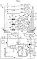
- Fig. 4 illustrates a refrigeration cycle apparatus 30 according to the third embodiment.
- the refrigeration cycle apparatus 30 according to the third embodiment further includes a forward header 31, a return header 32, and an inter-header bypass valve 33. Further, a plurality of first load devices 100 and a plurality of second load devices 200 are connected to the forward header 31 and the return header 32.
- the refrigeration cycle apparatus 30 is provided with a plurality of second bypass valves 10 corresponding to the plurality of first load devices 100.
- Fig. 4 illustrates a state in the free-cooling combined operation mode.
- each second load device 200 is connected by the second heat medium passage 9 to one outlet 31b corresponding to the second load device 200 among the plurality of outlets 31b of the forward header 31.
- the inlet of each second bypass valve 10 is connected by a heat medium passage 34 to one outlet 31b corresponding to the second bypass valve 10 among the plurality of outlets 31b of the forward header 31.
- An upstream portion of a heat medium passage 35 is connected to the outlet of the first bypass valve 8.
- the downstream portion of the heat medium passage 35 has a plurality of branch pipes 36 corresponding to the plurality of first load devices 100.
- Each branch pipe 36 is connected to the heat medium inlet of one first load device 100 corresponding to the branch pipe 36 among the plurality of first load devices 100.
- Each branch pipe 36 is provided with a check valve 37 and a branch portion 38.
- the branch portion 38 is provided in the branch pipe 36 between the check valve 37 and the first load device 100.
- the outlet of each second bypass valve 10 is connected by a heat medium passage 39 to the branch portion 38 of the branch pipe 36 connected to one first load device 100 corresponding to the second bypass valve 10 among the plurality of first load devices 100.
- the heat medium flowing out of the second heat exchanger 5 to the forward header 31 flows into one first load device 100 corresponding to the second bypass valve 10 among the plurality of first load devices 100.
- the check valve 37 prevents the heat medium from flowing into the other first load device 100.
- the system may be configured such that the number of first load devices 100 to be operated among the plurality of first load devices 100 can be changed.
- the number of first load devices 100 to be operated may be changed by closing a valve (not illustrated) provided in each heat medium passage 26 or each branch pipe 36 and stopping the supply of the heat medium to the first load device 100 the operation of which is to be stopped.
- the number of first load devices 100 to be operated may be changed by providing a bypass passage (not illustrated) that bypasses each of the first load devices 100 and allowing the heat medium to flow so as to bypass the first load device 100 the operation of which is to be stopped.
- the system may be configured such that the number of second load devices 200 to be operated among the plurality of second load devices 200 can be changed.
- the number of second load devices 200 to be operated may be changed by closing a valve (not illustrated) provided in each second heat medium passage 9 or each heat medium passage 27 and stopping the supply of the heat medium to the second load device 200 the operation of which is to be stopped.
- the number of second load devices 200 to be operated may be changed by providing a bypass passage (not illustrated) that bypasses each of the second load devices 200 and allowing the heat medium to flow so as to bypass the second load device 200 the operation of which is to be stopped.
- the inter-header bypass valve 33 to adjust the inter-header pressure difference, it can be more reliably ensured that the flow rate of the heat medium supplied to each of the first load devices 100 and the flow rate of the heat medium supplied to each of the second load devices 200 become appropriate values. In particular, even when the number of first load devices 100 to be operated or the number of second load devices 200 to be operated changes, it is possible to reliably supply the heat medium at an appropriate flow rate.
- the amount of heat medium flowing into the first load device 100 from the second heat exchanger 5 can be individually adjusted in the free-cooling combined operation mode. For example, by opening only the second bypass valve 10 corresponding to the first load device 100 having insufficient cooling capability among the plurality of second bypass valves 10, it is possible to supply the heat medium from the second heat exchanger 5 only to the first load device 100 having an insufficient cooling capability.
Landscapes
- Engineering & Computer Science (AREA)
- Mechanical Engineering (AREA)
- General Engineering & Computer Science (AREA)
- Physics & Mathematics (AREA)
- Thermal Sciences (AREA)
- Chemical & Material Sciences (AREA)
- Combustion & Propulsion (AREA)
- Signal Processing (AREA)
- Sustainable Development (AREA)
- Life Sciences & Earth Sciences (AREA)
- Fuzzy Systems (AREA)
- Mathematical Physics (AREA)
- Other Air-Conditioning Systems (AREA)
- Air Conditioning Control Device (AREA)
Abstract
Description
- The present disclosure relates to a refrigeration cycle apparatus.
- PTL 1 below discloses an air-conditioning operation method using free cooling. In this air-conditioning operation method, a low-temperature cold water tank and a high-temperature cold water tank are provided, and in an intermediate period, low-temperature cold water produced by a refrigerator is supplied to the low-temperature cold water tank for latent heat treatment, and high-temperature cold water produced by a cooling tower is supplied to the high-temperature cold water tank for sensible heat treatment. In summer or winter, high-temperature cold water in the high-temperature cold water tank is produced using low-temperature cold water produced by the refrigerator or low-temperature cold water produced by the cooling tower.
- [PTL 1]
JP 5503461 A - The conventional technology described above requires two water tanks and requires two pumps for supplying water between each water tank and a load, which causes a problem of high cost.
- An object of present disclosure, which has been made in order to solve the above problem, is to provide a refrigeration cycle apparatus that has a simple structure and is advantageous in increasing opportunities to utilize free cooling.
- A refrigeration cycle apparatus according to the present invention includes: a compressor to compress refrigerant; a first heat exchanger to cool the refrigerant compressed by the compressor with outdoor air; a decompressor to reduce a pressure of the refrigerant; a second heat exchanger to cool a heat medium with the refrigerant decompressed by the decompressor; a third heat exchanger to cool the heat medium with the outdoor air; a first heat medium passage connecting a heat medium outlet of the third heat exchanger to a heat medium inlet of the second heat exchanger; a first bypass valve to allow the heat medium to flow from the first heat medium passage into a first load device; a second heat medium passage to allow the heat medium flowing out of the second heat exchanger to flow into a second load device; a second bypass valve to allow the heat medium flowing out of the second heat exchanger to flow into the first load device; a return passage through which the heat medium returning from the first load device and the heat medium returning from the second load device pass; and a flow path switching valve to switch between a first mode in which the heat medium flows into the first heat medium passage from the return passage without passing through the third heat exchanger and a second mode in which the heat medium flows into the third heat exchanger from the return passage.
- According to the present disclosure, it is possible to provide a refrigeration cycle apparatus that has a simple structure and is advantageous in increasing opportunities to utilize free cooling.
-
-
Fig. 1 is a diagram illustrating a refrigeration cycle apparatus according to a first embodiment. -
Fig. 2 is a diagram illustrating a state in which the refrigeration cycle apparatus is being operated in a free-cooling combined operation mode. -
Fig. 3 is a diagram illustrating a refrigeration cycle apparatus according to a second embodiment. -
Fig. 4 is a diagram illustrating a refrigeration cycle apparatus according to a third embodiment. - Embodiments will be described below with reference to the drawings. In the drawings, common or corresponding elements are denoted by the same reference numerals, and the description thereof is simplified or omitted. In the present disclosure, the outside of a building is referred to as "outdoor", the inside of a room of the building is referred to as "indoor", the air outside the building is referred to as "outdoor air", and the air inside the room of the building is referred to as "indoor air". The temperature of the outdoor air is referred to as an "outside air temperature".
-
Fig. 1 is a diagram illustrating a refrigeration cycle apparatus 1 according to a first embodiment. As illustrated inFig. 1 , a refrigeration cycle apparatus 1 is provided with: acompressor 2 configured to compress refrigerant; afirst heat exchanger 3 configured to cool the refrigerant compressed by thecompressor 2 with outdoor air; adecompressor 4 configured to reduce a pressure of the refrigerant; asecond heat exchanger 5 configured to cool a heat medium with the refrigerant decompressed by thedecompressor 4; athird heat exchanger 6 configured to cool the heat medium with the outdoor air; a firstheat medium passage 7 connecting a heat medium outlet of thethird heat exchanger 6 to a heat medium inlet of thesecond heat exchanger 5; afirst bypass valve 8 configured to allow the heat medium to flow from the firstheat medium passage 7 into afirst load device 100; a secondheat medium passage 9 configured to allow the heat medium flowing out of thesecond heat exchanger 5 to flow into asecond load device 200; asecond bypass valve 10 configured to allow the heat medium flowing out of thesecond heat exchanger 5 to flow into thefirst load device 100; areturn passage 11 through which the heat medium returning from thefirst load device 100 and the heat medium returning from thesecond load device 200 pass; a flowpath switching valve 12 configured to switch between a first mode in which the heat medium flows into the firstheat medium passage 7 from thereturn passage 11 without passing through thethird heat exchanger 6 and a second mode in which the heat medium flows into thethird heat exchanger 6 from thereturn passage 11. - A substance used as the refrigerant in the present disclosure is not particularly limited but may be, for example, any of CO2, HFC, HFO, and hydrocarbon.
- A substance used as the heat medium in the present disclosure is typically liquid water. However, a liquid except for water, such as an aqueous solution of calcium chloride, an aqueous solution of ethylene glycol, an aqueous solution of propylene glycol, or alcohol, may be used as the heat medium. In the illustrated example, a
heat medium pump 13 for circulating the heat medium is provided in thereturn passage 11. - The
first heat exchanger 3 is configured to cool the heat medium by heat exchange using outdoor air. For example, thefirst heat exchanger 3 may be configured to directly exchange heat between the outdoor air and the heat medium in a closed type cooling tower. Alternatively, thefirst heat exchanger 3 may be configured to exchange heat between cooling water cooled by outdoor air in an open type cooling tower and the heat medium. - The
third heat exchanger 6 is configured to cool the heat medium by heat exchange using outdoor air. For example, thethird heat exchanger 6 may be configured to directly exchange heat between the outdoor air and the heat medium in the closed type cooling tower. Alternatively, thethird heat exchanger 6 may be configured to exchange heat between the cooling water cooled by outdoor air in the open type cooling tower and the heat medium. - In the illustrated example, the
first heat exchanger 3 and thethird heat exchanger 6 are disposed adjacent to each other. In the illustrated example, ablower 14 for feeding outdoor air to thefirst heat exchanger 3 and thethird heat exchanger 6 is provided. Theblower 14 may not be provided. In place of the illustrated example, thethird heat exchanger 6 may be disposed at a position away from thefirst heat exchanger 3. In this case, a blower for feeding outdoor air to thefirst heat exchanger 3 and a blower for feeding outdoor air to thethird heat exchanger 6 may be provided separately. - In the present embodiment, an example will be mainly described where the
first load device 100 and thesecond load device 200 are configured to perform air conditioning in a room by using a heat medium. However, the present disclosure is not limited to a system for performing air conditioning. For example, one or both of thefirst load device 100 and thesecond load device 200 may be configured to cool a production apparatus by using a heat medium. - The
first load device 100 may include a heat exchanger for exchanging heat between the indoor air and the heat medium. Thefirst load device 100 may be formed of, for example, a fan coil unit. Thefirst load device 100 may be configured to mainly handle a sensible heat load in air conditioning. That is, thefirst load device 100 may be configured to mainly lower the temperature of the indoor air. - The air flowing into the room from outside is hereinafter referred to as "ventilation air". The
second load device 200 may include a heat exchanger for exchanging heat between the ventilation air and the heat medium. Thesecond load device 200 may be formed of what is generally called an outside air processing air conditioner. Thesecond load device 200 may be configured to mainly handle latent heat load in air conditioning. That is, in order to reduce humidity, thesecond load device 200 may be configured to mainly cool air to condense water vapor. -
Fig. 1 illustrates a state in which the refrigeration cycle apparatus 1 is being operated in a chiller independent operation mode. In the chiller independent operation mode, the heat medium is cooled by operating thecompressor 2 without performing free cooling by thethird heat exchanger 6. The refrigeration cycle apparatus 1 in the chiller independent operation mode operates as follows. The high-temperature and high-pressure refrigerant compressed by thecompressor 2 flows into thefirst heat exchanger 3. The refrigerant cooled by the outdoor air in thefirst heat exchanger 3 is decompressed when passing through thedecompressor 4. Thefirst bypass valve 8 is closed. Thesecond bypass valve 10 is open. The flowpath switching valve 12 is in the first mode. In thesecond heat exchanger 5, the heat medium is cooled by exchanging heat between the low-temperature and low-pressure refrigerant flowing out of thedecompressor 4 and the heat medium. A part of the heat medium flowing out of thesecond heat exchanger 5 is supplied to thefirst load device 100 through thesecond bypass valve 10. The remainder of the heat medium flowing out of thesecond heat exchanger 5 is supplied to thesecond load device 200 through the secondheat medium passage 9. The heat medium returned from thefirst load device 100 and the heat medium returned from thesecond load device 200 merge and flow through thereturn passage 11. The heat medium flows from thereturn passage 11 into the firstheat medium passage 7 without passing through thethird heat exchanger 6. The entire amount of the heat medium flowing into the firstheat medium passage 7 flows into thesecond heat exchanger 5. -
Fig. 2 is a diagram illustrating a state in which the refrigeration cycle apparatus 1 is being operated in the free-cooling combined operation mode. In the free-cooling combined operation mode, free cooling by thethird heat exchanger 6 and the operation of thecompressor 2 are used in combination to cool the heat medium. The refrigeration cycle apparatus 1 in the free-cooling combined operation mode operates as follows. The refrigerant circulates through the same path as in the chiller independent operation mode. Thefirst bypass valve 8 is open. Thesecond bypass valve 10 is closed. The flowpath switching valve 12 is in the second mode. The heat medium returned from thefirst load device 100 and the heat medium returned from thesecond load device 200 merge and flow through thereturn passage 11. The heat medium having passed through thereturn passage 11 flows into thethird heat exchanger 6. The heat medium cooled by the outdoor air in thethird heat exchanger 6 flows into the firstheat medium passage 7. A part of the heat medium flowing through the firstheat medium passage 7 is supplied to thefirst load device 100 through thefirst bypass valve 8. The remainder of the heat medium flowing through the firstheat medium passage 7 flows into thesecond heat exchanger 5. The heat medium cooled by the refrigerant in thesecond heat exchanger 5 is supplied to thesecond load device 200 through the secondheat medium passage 9. - In order to treat the latent heat by the
second load device 200, the temperature of the heat medium flowing from thesecond heat exchanger 5 into thesecond load device 200 needs to be made lower than the dew point temperature. The greater the flow rate of the heat medium flowing through thesecond heat exchanger 5, the greater the power consumption of thecompressor 2 when the heat medium is cooled to an isothermal temperature. The flow rate of the heat medium flowing through thesecond heat exchanger 5 in the free-cooling combined operation mode is smaller than that in the chiller independent operation mode. Therefore, in the free-cooling combined operation mode, the power consumption of thecompressor 2 can be reduced as compared with the chiller independent operation mode, and energy saving can be achieved. - In the free-cooling combined operation mode, the heat medium cooled by the free cooling of the
third heat exchanger 6 flows into thefirst load device 100. The temperature of the heat medium cooled by free cooling varies in accordance with the outside air temperature. The temperature of the heat medium flowing into thefirst load device 100, which treats sensible heat, can be higher than the dew point temperature. In the free-cooling combined operation mode, the heat medium cooled by free cooling can be supplied to thefirst load device 100, and the heat medium further cooled by thesecond heat exchanger 5 to a temperature lower than the dew point temperature can be supplied to thesecond load device 200. Therefore, in the refrigeration cycle apparatus 1 of the present embodiment, free cooling can be utilized even when the temperature of the heat medium cooled by free cooling is higher than the dew point temperature. As a result, opportunities to utilize free cooling can be increased, and energy saving can thus be achieved. Further, according to the present embodiment, since the above effect can be achieved by the refrigeration cycle apparatus 1 having a simple configuration, the product cost can be reduced. For example, the simple configuration can be achieved by not requiring a tank that separately stores the heat medium cooled by free cooling and the heat medium further cooled by thesecond heat exchanger 5. Moreover, the simple configuration can be achieved by the common heatmedium pump 13 circulating both the heat medium cooled by free cooling and the heat medium further cooled by thesecond heat exchanger 5. - In the free-cooling combined operation mode, the
second bypass valve 10 may be slightly opened. Thereby, the heat medium having passed through thesecond bypass valve 10 mixes with the heat medium passing through thefirst bypass valve 8, so that the temperature of the heat medium flowing into thefirst load device 100 can be lowered. - The refrigeration cycle apparatus 1 may further include
control circuitry 50 configured to control the operation of thefirst bypass valve 8, the operation of thesecond bypass valve 10, and the operation of the flowpath switching valve 12. The addition of thecontrol circuitry 50 has an advantage that these operations can be automated. - The
control circuitry 50 may be configured to close thefirst bypass valve 8 and open thesecond bypass valve 10 when the flowpath switching valve 12 is in the first mode. This can automate the operation of the chiller independent operation mode. - The
control circuitry 50 may be configured to perform a process of opening thefirst bypass valve 8 and a process of closing thesecond bypass valve 10 when the flowpath switching valve 12 is in the second mode. Thecontrol circuitry 50 may be configured to perform, when the flowpath switching valve 12 is in the second mode, a process of opening thefirst bypass valve 8 and a process of making the opening degree of thesecond bypass valve 10 smaller than the opening degree when the flowpath switching valve 12 is in the first mode. These can automate the operation of the free-cooling combined operation mode. - Although not illustrated, the refrigeration cycle apparatus 1 may be operated in a free-cooling independent operation mode in which the heat medium is cooled only by free cooling without operating the
compressor 2. In the free-cooling independent operation mode, thecompressor 2 is stopped, the flowpath switching valve 12 is set to the second mode, thefirst bypass valve 8 is opened, and thesecond bypass valve 10 is fully closed. - The
control circuitry 50 may be configured to vary the operating speed of thecompressor 2 by, for example, inverter control to adjust the capability of cooling the heat medium. Thecontrol circuitry 50 may be configured to further control at least one of the operation of thedecompressor 4, the operation of theheat medium pump 13, and the operation of theblower 14. Thedecompressor 4 may be an expansion valve with an adjustable opening degree. Thecontrol circuitry 50 may be configured to vary the operating speed of theheat medium pump 13 by, for example, inverter control, thus adjusting the circulating flow rate of the heat medium. Thecontrol circuitry 50 may be configured to vary the operating speed of theblower 14 by, for example, inverter control, thus adjusting the air flow rate. Thecontrol circuitry 50 may control at least one of the operating speed of thecompressor 2, the circulating flow rate of the heat medium, the opening degree of thedecompressor 4, and the operating speed of theblower 14 so that each of thefirst load device 100 and thesecond load device 200 satisfies the required capability. - In the following description, the temperature of the heat medium passing through the
return passage 11 is referred to as a "return temperature". The refrigeration cycle apparatus 1 may further include an outsideair temperature sensor 15 for detecting the outside air temperature and areturn temperature sensor 16 for detecting the return temperature. Thecontrol circuitry 50 may switch the flowpath switching valve 12 from the first mode to the second mode when the outside air temperature is lower than the return temperature, and the difference between the return temperature and the outside air temperature is larger than a reference. That is, thecontrol circuitry 50 may be configured to shift from the chiller independent operation mode to the free-cooling combined operation mode when the outside air temperature is lower than the return temperature, and the difference between the return temperature and the outside air temperature is larger than the above reference. This increases the opportunity to use the free-cooling combined operation mode instead of the chiller independent operation mode, thereby saving energy. - In the following description, the cooling capability of the heat medium supplied by the refrigeration cycle apparatus 1 to the
first load device 100 and thesecond load device 200 is referred to as a "supplied cooling capability". The refrigeration cycle apparatus 1 may further include a capability shortage detector for detecting the shortage of the supplied cooling capability. Thecontrol circuitry 50 may have the function of the capability shortage detector. For example, the capability shortage detector may determine whether the supplied cooling capability is sufficient for the sensible heat capability, which is the cooling capability required by thefirst load device 100, and the latent heat capability, which is the cooling capability required by thesecond load device 200. The capability shortage detector may detect the shortage of the supplied cooling capability based on information obtained from an indoor sensor (not illustrated) that detects the temperature and humidity of the indoor air. For example, the capability shortage detector may detect the shortage of the supplied cooling capability based on the difference between an actual indoor temperature and a target value and the difference between an actual indoor humidity and a target value. - When the supplied cooling capability becomes insufficient while with the flow
path switching valve 12 is in the second mode, thecontrol circuitry 50 may reduce the opening degree of thefirst bypass valve 8 and increase the opening degree of thesecond bypass valve 10. That is, thecontrol circuitry 50 may be configured to lower the opening degree of thefirst bypass valve 8 and to increase the opening degree of thesecond bypass valve 10 when the supplied cooling capability becomes insufficient during the execution of the free-cooling combined operation mode. When the opening degree of thefirst bypass valve 8 decreases and that of thesecond bypass valve 10 increases, the flow rate of the heat medium flowing into thesecond heat exchanger 5 and cooled by the refrigerant increases, so that the supplied cooling capability increases. As a result, the shortage of supplied cooling capability is solved. - Further, during the execution of the free-cooling combined operation mode, the
control circuitry 50 may shift to the free-cooling independent operation mode in response to the difference between the return temperature and the outside air temperature. Alternatively, during the execution of the free-cooling combined operation mode, thecontrol circuitry 50 may shift to the free-cooling independent operation mode in response to the fact that the supplied cooling capability is sufficient. - The refrigeration cycle apparatus 1 of the present embodiment will be further described below. The inlet of the
first bypass valve 8 is connected to abranch portion 17 provided in the firstheat medium passage 7. The outlet of thefirst bypass valve 8 is connected to the heat medium inlet of thefirst load device 100 by aheat medium passage 18. The secondheat medium passage 9 connects the heat medium outlet of thesecond heat exchanger 5 to the heat medium inlet of thesecond load device 200. The inlet of thesecond bypass valve 10 is connected to abranch portion 19 provided in the secondheat medium passage 9. The outlet of thesecond bypass valve 10 is connected to abranch portion 20 provided in theheat medium passage 18. - The upstream portion of the
return passage 11 is connected to both the heat medium outlet of thefirst load device 100 and the heat medium outlet of thesecond load device 200. The flowpath switching valve 12 corresponds to a three-way valve having aninlet 12a, afirst outlet 12b, and asecond outlet 12c. Theinlet 12a is connected to the downstream portion of thereturn passage 11. Thefirst outlet 12b is connected to abranch portion 21 provided in the firstheat medium passage 7. Thesecond outlet 12c is connected to the heat medium inlet of thethird heat exchanger 6 by aheat medium passage 22. In the first mode, the flowpath switching valve 12 communicates theinlet 12a with thefirst outlet 12b and closes thesecond outlet 12c. In the second mode, the flowpath switching valve 12 communicates theinlet 12a with thesecond outlet 12c and closes thefirst outlet 12b. - The refrigeration cycle apparatus 1 of the illustrated example further includes a refrigerant circuit switching valve 23 for switching between a normal cycle circuit and a reverse cycle circuit. As illustrated in
Figs. 1 and2 , the normal cycle circuit is a circuit in which high-temperature and high-pressure refrigerant discharged from thecompressor 2 flows into thefirst heat exchanger 3 through the refrigerant circuit switching valve 23. Although not illustrated, the reverse cycle circuit is a circuit in which high-temperature and high-pressure refrigerant discharged from thecompressor 2 flows into thesecond heat exchanger 5 through the refrigerant circuit switching valve 23. By adding the refrigerant circuit switching valve 23, the refrigeration cycle apparatus 1 can perform a heating operation using the reverse cycle circuit. In the heating operation, the heat medium is heated by the high-temperature and high-pressure refrigerant in thesecond heat exchanger 5. For example, by supplying the heat medium heated by the heating operation to thefirst load device 100 and thesecond load device 200, the inside of the room can be heated. In the heating operation, the high-pressure refrigerant that has passed through thesecond heat exchanger 5 is decompressed by thedecompressor 4. The decompressed refrigerant absorbs the heat of the outdoor air in thefirst heat exchanger 3 and is evaporated. The evaporated refrigerant is sucked into thecompressor 2. However, the refrigeration cycle apparatus 1 of the present disclosure may not include the refrigerant circuit switching valve 23, that is, may not perform the heating operation using the reverse cycle circuit. - Each function of the
control circuitry 50 may be achieved by a processing circuit. The processing circuit of thecontrol circuitry 50 may include at least one processor and at least one memory. At least one processor may read and execute a program stored in at least one memory to implement each function of thecontrol circuitry 50. The processing circuit of thecontrol circuitry 50 may include at least one dedicated hardware. - Next, a second embodiment will be described with reference to
Fig. 3 , focusing on the differences from the first embodiment described above, and elements common to or corresponding to the elements described above are denoted by the same reference numerals to simplify or omit the common description. -
Fig. 3 is a diagram illustrating arefrigeration cycle apparatus 24 according to the second embodiment. As illustrated inFig. 3 , therefrigeration cycle apparatus 24 according to the second embodiment further includes aforward header 31, areturn header 32, and aninter-header bypass valve 33. Theforward header 31 has a predetermined volume. Thereturn header 32 has a predetermined volume.Fig. 3 illustrates a state in the free-cooling combined operation mode. - The
forward header 31 includes aninlet 31a and a plurality ofoutlets 31b. Theinlet 31a is connected to the heat medium outlet of thesecond heat exchanger 5 by aheat medium passage 25. The secondheat medium passage 9 connects one of the plurality ofoutlets 31b to the heat medium inlet of thesecond load device 200. The inlet of thesecond bypass valve 10 is connected to another one of the plurality ofoutlets 31b. - The
return header 32 includes anoutlet 32a and a plurality ofinlets 32b. The upstream portion of thereturn passage 11 is connected to theoutlet 32a. One of the plurality ofinlets 32b is connected to the heat medium outlet of thefirst load device 100 by aheat medium passage 26. Another one of the plurality ofinlets 32b is connected to the heat medium outlet of thesecond load device 200 by aheat medium passage 27. - The
inter-header bypass passage 28 connects theforward header 31 to thereturn header 32. Theinter-header bypass passage 28 is provided with aninter-header bypass valve 33. When theinter-header bypass valve 33 is opened, the heat medium can move between theforward header 31 and thereturn header 32 through theinter-header bypass passage 28. - In the following description, the difference between the pressure of the heat medium in the
forward header 31 and that in thereturn header 32 will be referred to as an "inter-header pressure difference". According to the present embodiment, the inter-header pressure difference can be adjusted by changing the opening degree of theinter-header bypass valve 33. By adjusting the inter-header pressure difference, it can be more reliably ensured that the flow rate of the heat medium supplied to thefirst load device 100 and the flow rate of the heat medium supplied to thesecond load device 200 are appropriate values. In particular, even when the distance to thefirst load device 100 or the distance to thesecond load device 200 is long, it is possible to reliably supply the heat medium at an appropriate flow rate. - The
control circuitry 50 may be configured to control the operation of theinter-header bypass valve 33 so that the inter-header pressure difference detected by a sensor (not illustrated) matches a target. - Next, a third embodiment will be described with reference to
Fig. 4 , focusing on the differences from the first embodiment and the second embodiment described above, and elements common to or corresponding to the elements described above are denoted by the same reference numerals to simplify or omit the common description. -
Fig. 4 illustrates arefrigeration cycle apparatus 30 according to the third embodiment. As illustrated inFig. 4 , therefrigeration cycle apparatus 30 according to the third embodiment further includes aforward header 31, areturn header 32, and aninter-header bypass valve 33. Further, a plurality offirst load devices 100 and a plurality ofsecond load devices 200 are connected to theforward header 31 and thereturn header 32. Therefrigeration cycle apparatus 30 is provided with a plurality ofsecond bypass valves 10 corresponding to the plurality offirst load devices 100.Fig. 4 illustrates a state in the free-cooling combined operation mode. - The heat medium inlet of each
second load device 200 is connected by the secondheat medium passage 9 to oneoutlet 31b corresponding to thesecond load device 200 among the plurality ofoutlets 31b of theforward header 31. The inlet of eachsecond bypass valve 10 is connected by aheat medium passage 34 to oneoutlet 31b corresponding to thesecond bypass valve 10 among the plurality ofoutlets 31b of theforward header 31. - An upstream portion of a
heat medium passage 35 is connected to the outlet of thefirst bypass valve 8. The downstream portion of theheat medium passage 35 has a plurality ofbranch pipes 36 corresponding to the plurality offirst load devices 100. Eachbranch pipe 36 is connected to the heat medium inlet of onefirst load device 100 corresponding to thebranch pipe 36 among the plurality offirst load devices 100. Eachbranch pipe 36 is provided with acheck valve 37 and abranch portion 38. Thebranch portion 38 is provided in thebranch pipe 36 between thecheck valve 37 and thefirst load device 100. The outlet of eachsecond bypass valve 10 is connected by aheat medium passage 39 to thebranch portion 38 of thebranch pipe 36 connected to onefirst load device 100 corresponding to thesecond bypass valve 10 among the plurality offirst load devices 100. - When one of the
second bypass valves 10 is opened, the heat medium flowing out of thesecond heat exchanger 5 to theforward header 31 flows into onefirst load device 100 corresponding to thesecond bypass valve 10 among the plurality offirst load devices 100. At this time, thecheck valve 37 prevents the heat medium from flowing into the otherfirst load device 100. - The system may be configured such that the number of
first load devices 100 to be operated among the plurality offirst load devices 100 can be changed. For example, the number offirst load devices 100 to be operated may be changed by closing a valve (not illustrated) provided in eachheat medium passage 26 or eachbranch pipe 36 and stopping the supply of the heat medium to thefirst load device 100 the operation of which is to be stopped. Alternatively, the number offirst load devices 100 to be operated may be changed by providing a bypass passage (not illustrated) that bypasses each of thefirst load devices 100 and allowing the heat medium to flow so as to bypass thefirst load device 100 the operation of which is to be stopped. - The system may be configured such that the number of
second load devices 200 to be operated among the plurality ofsecond load devices 200 can be changed. For example, the number ofsecond load devices 200 to be operated may be changed by closing a valve (not illustrated) provided in each secondheat medium passage 9 or eachheat medium passage 27 and stopping the supply of the heat medium to thesecond load device 200 the operation of which is to be stopped. Alternatively, the number ofsecond load devices 200 to be operated may be changed by providing a bypass passage (not illustrated) that bypasses each of thesecond load devices 200 and allowing the heat medium to flow so as to bypass thesecond load device 200 the operation of which is to be stopped. - According to the present embodiment, by using the
inter-header bypass valve 33 to adjust the inter-header pressure difference, it can be more reliably ensured that the flow rate of the heat medium supplied to each of thefirst load devices 100 and the flow rate of the heat medium supplied to each of thesecond load devices 200 become appropriate values. In particular, even when the number offirst load devices 100 to be operated or the number ofsecond load devices 200 to be operated changes, it is possible to reliably supply the heat medium at an appropriate flow rate. - In the present embodiment, since the plurality of
second bypass valves 10 corresponding to the plurality offirst load devices 100 are provided, the amount of heat medium flowing into thefirst load device 100 from thesecond heat exchanger 5 can be individually adjusted in the free-cooling combined operation mode. For example, by opening only thesecond bypass valve 10 corresponding to thefirst load device 100 having insufficient cooling capability among the plurality ofsecond bypass valves 10, it is possible to supply the heat medium from thesecond heat exchanger 5 only to thefirst load device 100 having an insufficient cooling capability. -
- 1
- refrigeration cycle apparatus
- 2
- compressor
- 3
- first heat exchanger
- 4
- decompressor
- 5
- second heat exchanger
- 6
- third heat exchanger
- 7
- first heat medium passage
- 8
- first bypass valve
- 9
- second heat medium passage
- 10
- second bypass valve
- 11
- return passage
- 12
- flow path switching valve
- 12a
- inlet
- 12b
- first outlet
- 12c
- second outlet
- 13
- heat medium pump
- 14
- blower
- 15
- outside air temperature sensor
- 16
- return temperature sensor
- 17
- branch portion
- 18
- heat medium passage
- 19
- branch portion
- 20
- branch portion
- 21
- branch portion
- 22
- heat medium passage
- 23
- refrigerant circuit switching valve
- 24
- refrigeration cycle apparatus
- 25
- heat medium passage
- 26
- heat medium passage
- 27
- heat medium passage
- 28
- inter-header bypass passage
- 30
- refrigeration cycle apparatus
- 31
- forward header
- 31a
- inlet
- 31b
- outlet
- 32
- return header
- 32a
- outlet
- 32b
- inlet
- 33
- inter-header bypass valve
- 34
- heat medium passage
- 35
- heat medium passage
- 36
- branch pipe
- 37
- check valve
- 38
- branch portion
- 39
- heat medium passage
- 50
- control circuitry
- 100
- first load device
- 200
- second load device
Claims (7)
- A refrigeration cycle apparatus comprising:a compressor to compress refrigerant;a first heat exchanger to cool the refrigerant compressed by the compressor with outdoor air;a decompressor to reduce a pressure of the refrigerant;a second heat exchanger to cool a heat medium with the refrigerant decompressed by the decompressor;a third heat exchanger to cool the heat medium with the outdoor air;a first heat medium passage connecting a heat medium outlet of the third heat exchanger to a heat medium inlet of the second heat exchanger;a first bypass valve to allow the heat medium to flow from the first heat medium passage into a first load device;a second heat medium passage to allow the heat medium flowing out of the second heat exchanger to flow into a second load device;a second bypass valve to allow the heat medium flowing out of the second heat exchanger to flow into the first load device;a return passage through which the heat medium returning from the first load device and the heat medium returning from the second load device pass; anda flow path switching valve to switch between a first mode in which the heat medium flows into the first heat medium passage from the return passage without passing through the third heat exchanger and a second mode in which the heat medium flows into the third heat exchanger from the return passage.
- The refrigeration cycle apparatus according to claim 1, further comprising control circuitry to control an operation of the first bypass valve, an operation of the second bypass valve, and an operation of the flow path switching valve.
- The refrigeration cycle apparatus according to claim 2, further comprising:an outside air temperature sensor to detect an outside air temperature that is a temperature of the outdoor air; anda return temperature sensor to detect a return temperature that is a temperature of the heat medium passing through the return passage,wherein the control circuitry is configured to switch the flow path switching valve to the second mode when the outside air temperature is lower than the return temperature, and a difference between the return temperature and the outside air temperature is larger than a reference.
- The refrigeration cycle apparatus according to claim 2 or 3, whereinthe control circuitry is configured to close the first bypass valve and open the second bypass valve when the flow path switching valve is in the first mode, andthe control circuitry is configured to perform, when the flow path switching valve is in the second mode, a process of opening the first bypass valve and a process of closing the second bypass valve or making an opening degree of the second bypass valve smaller than the opening degree in the first mode.
- The refrigeration cycle apparatus according to any one of claims 2 to 4, further comprisinga capability shortage detector to detect a shortage of a supplied cooling capability that is a cooling capability of the heat medium supplied to the first load device and the second load device,wherein the control circuitry is configured to decrease an opening degree of the first bypass valve and increase the opening degree of the second bypass valve when the supplied cooling capability becomes insufficient while the flow path switching valve is in the second mode.
- The refrigeration cycle apparatus according to any one of claims 1 to 5, further comprising:the first load device including a heat exchanger for exchanging heat between indoor air and the heat medium; andthe second load device including a heat exchanger for exchanging heat between ventilation air flowing from outdoor to indoor and the heat medium.
- The refrigeration cycle apparatus according to any one of claims 1 to 6, further comprising:a forward header connected to each of a heat medium outlet of the second heat exchanger, the second bypass valve, and the second heat medium passage;a return header connected to each of the return passage, the first load device, and the second load device;an inter-header bypass passage connecting the forward header to the return header; andan inter-header bypass valve provided in the inter-header bypass passage.
Applications Claiming Priority (1)
| Application Number | Priority Date | Filing Date | Title |
|---|---|---|---|
| PCT/JP2020/021141 WO2021240729A1 (en) | 2020-05-28 | 2020-05-28 | Refrigeration cycle device |
Publications (2)
| Publication Number | Publication Date |
|---|---|
| EP4160107A1 true EP4160107A1 (en) | 2023-04-05 |
| EP4160107A4 EP4160107A4 (en) | 2023-07-12 |
Family
ID=78723132
Family Applications (1)
| Application Number | Title | Priority Date | Filing Date |
|---|---|---|---|
| EP20937397.6A Withdrawn EP4160107A4 (en) | 2020-05-28 | 2020-05-28 | REFRIGERATION CIRCUIT DEVICE |
Country Status (5)
| Country | Link |
|---|---|
| US (1) | US20230137885A1 (en) |
| EP (1) | EP4160107A4 (en) |
| JP (1) | JP7306582B2 (en) |
| CN (1) | CN115667815A (en) |
| WO (1) | WO2021240729A1 (en) |
Families Citing this family (2)
| Publication number | Priority date | Publication date | Assignee | Title |
|---|---|---|---|---|
| WO2025203468A1 (en) * | 2024-03-28 | 2025-10-02 | 三菱電機株式会社 | Air conditioner |
| WO2026078959A1 (en) * | 2024-10-07 | 2026-04-16 | 株式会社デンソー | Refrigeration cycle device |
Family Cites Families (17)
| Publication number | Priority date | Publication date | Assignee | Title |
|---|---|---|---|---|
| JP2979061B2 (en) * | 1991-01-31 | 1999-11-15 | 三機工業株式会社 | Natural cooling air conditioner |
| US6082128A (en) * | 1998-11-12 | 2000-07-04 | Daimlerchrysler Corporation | Reversible air conditioning and heat pump HVAC system for electric vehicles |
| AU751294C (en) * | 2001-07-13 | 2005-04-07 | Baltimore Aircoil Company Inc. | System and method of cooling |
| JP4630702B2 (en) * | 2005-03-28 | 2011-02-09 | 三機工業株式会社 | Heat source system optimum operation control device |
| JP4829147B2 (en) * | 2007-03-01 | 2011-12-07 | 三機工業株式会社 | Air conditioning equipment |
| US7997092B2 (en) * | 2007-09-26 | 2011-08-16 | Carrier Corporation | Refrigerant vapor compression system operating at or near zero load |
| JP5363212B2 (en) * | 2008-09-30 | 2013-12-11 | 株式会社日立製作所 | Air conditioning system |
| CN201539928U (en) * | 2009-09-09 | 2010-08-04 | 北京康孚环境控制有限公司 | Cooling tower and water chilling unit set combined cold supply system |
| JP5503461B2 (en) * | 2010-08-26 | 2014-05-28 | 株式会社朝日工業社 | Air conditioning operation method using free cooling |
| JP6314821B2 (en) * | 2014-01-29 | 2018-04-25 | 株式会社デンソー | Air conditioner for vehicles |
| US10215452B2 (en) * | 2014-07-18 | 2019-02-26 | Mitsubishi Electric Corporation | Air conditioner |
| JP6320567B2 (en) * | 2015-01-13 | 2018-05-09 | 三菱電機株式会社 | Air conditioner |
| US10655504B2 (en) * | 2016-05-27 | 2020-05-19 | Denso International America, Inc. | Heat pump for warming engine coolant |
| WO2018116410A1 (en) * | 2016-12-21 | 2018-06-28 | 三菱電機株式会社 | Air conditioner |
| JP7316872B2 (en) * | 2019-08-06 | 2023-07-28 | サンデン株式会社 | TEMPERATURE ADJUSTMENT FOR VEHICLE HEAT DEVICE AND VEHICLE AIR CONDITIONER INCLUDING THE SAME |
| CN110513900A (en) * | 2019-08-23 | 2019-11-29 | 捷通智慧科技股份有限公司 | A kind of cooling device being used in combination based on closed cooling tower and water cooler |
| JP7243694B2 (en) * | 2019-10-15 | 2023-03-22 | 株式会社デンソー | refrigeration cycle equipment |
-
2020
- 2020-05-28 JP JP2022527397A patent/JP7306582B2/en active Active
- 2020-05-28 CN CN202080101142.0A patent/CN115667815A/en active Pending
- 2020-05-28 US US17/911,837 patent/US20230137885A1/en not_active Abandoned
- 2020-05-28 EP EP20937397.6A patent/EP4160107A4/en not_active Withdrawn
- 2020-05-28 WO PCT/JP2020/021141 patent/WO2021240729A1/en not_active Ceased
Also Published As
| Publication number | Publication date |
|---|---|
| CN115667815A (en) | 2023-01-31 |
| US20230137885A1 (en) | 2023-05-04 |
| WO2021240729A1 (en) | 2021-12-02 |
| EP4160107A4 (en) | 2023-07-12 |
| JPWO2021240729A1 (en) | 2021-12-02 |
| JP7306582B2 (en) | 2023-07-11 |
Similar Documents
| Publication | Publication Date | Title |
|---|---|---|
| US12392521B2 (en) | Air conditioning system | |
| JP6644154B2 (en) | Air conditioner | |
| EP2960597B1 (en) | Air conditioning device | |
| EP2975335B1 (en) | Air conditioner | |
| EP2960596B1 (en) | Air conditioning device | |
| EP2975336B1 (en) | Air conditioner | |
| EP3312528B1 (en) | Air conditioner | |
| EP3415839A1 (en) | Refrigeration cycle device | |
| US10317113B2 (en) | Air conditioner | |
| KR20170090290A (en) | Air conditioner | |
| US11274851B2 (en) | Air conditioning apparatus | |
| CN109140725B (en) | Multi-split air conditioning system and defrosting control method thereof | |
| US11892209B2 (en) | Multi-air conditioner for heating and cooling including a shut-off valve between indoor and outdoor units and control method thereof | |
| EP3228954A2 (en) | Cooling apparatus | |
| US20200182516A1 (en) | Air-conditioning apparatus | |
| CN207350468U (en) | Air-conditioning device | |
| US12529499B2 (en) | Air-conditioning apparatus and air-conditioning system | |
| EP4160107A1 (en) | Refrigeration cycle device | |
| KR100821728B1 (en) | Air conditioning system | |
| US10465935B2 (en) | Air-conditioning apparatus | |
| US20210207859A1 (en) | Controller of air conditioning apparatus, outdoor unit, relay unit, heat source unit, and air conditioning apparatus | |
| EP3715735B1 (en) | Air conditioning apparatus | |
| US20230375238A1 (en) | Refrigeration cycle apparatus | |
| CN109827275B (en) | Air handling equipment | |
| US20230131781A1 (en) | Refrigeration cycle apparatus |
Legal Events
| Date | Code | Title | Description |
|---|---|---|---|
| STAA | Information on the status of an ep patent application or granted ep patent |
Free format text: STATUS: THE INTERNATIONAL PUBLICATION HAS BEEN MADE |
|
| PUAI | Public reference made under article 153(3) epc to a published international application that has entered the european phase |
Free format text: ORIGINAL CODE: 0009012 |
|
| STAA | Information on the status of an ep patent application or granted ep patent |
Free format text: STATUS: REQUEST FOR EXAMINATION WAS MADE |
|
| 17P | Request for examination filed |
Effective date: 20221122 |
|
| AK | Designated contracting states |
Kind code of ref document: A1 Designated state(s): AL AT BE BG CH CY CZ DE DK EE ES FI FR GB GR HR HU IE IS IT LI LT LU LV MC MK MT NL NO PL PT RO RS SE SI SK SM TR |
|
| A4 | Supplementary search report drawn up and despatched |
Effective date: 20230614 |
|
| RIC1 | Information provided on ipc code assigned before grant |
Ipc: F24F 140/20 20180101ALI20230607BHEP Ipc: F24F 110/12 20180101ALI20230607BHEP Ipc: F24F 11/84 20180101ALI20230607BHEP Ipc: F24F 5/00 20060101ALI20230607BHEP Ipc: F25B 1/00 20060101AFI20230607BHEP |
|
| DAV | Request for validation of the european patent (deleted) | ||
| DAX | Request for extension of the european patent (deleted) | ||
| GRAP | Despatch of communication of intention to grant a patent |
Free format text: ORIGINAL CODE: EPIDOSNIGR1 |
|
| STAA | Information on the status of an ep patent application or granted ep patent |
Free format text: STATUS: GRANT OF PATENT IS INTENDED |
|
| INTG | Intention to grant announced |
Effective date: 20240206 |
|
| GRAJ | Information related to disapproval of communication of intention to grant by the applicant or resumption of examination proceedings by the epo deleted |
Free format text: ORIGINAL CODE: EPIDOSDIGR1 |
|
| STAA | Information on the status of an ep patent application or granted ep patent |
Free format text: STATUS: REQUEST FOR EXAMINATION WAS MADE |
|
| INTC | Intention to grant announced (deleted) | ||
| GRAP | Despatch of communication of intention to grant a patent |
Free format text: ORIGINAL CODE: EPIDOSNIGR1 |
|
| STAA | Information on the status of an ep patent application or granted ep patent |
Free format text: STATUS: GRANT OF PATENT IS INTENDED |
|
| INTG | Intention to grant announced |
Effective date: 20240715 |
|
| STAA | Information on the status of an ep patent application or granted ep patent |
Free format text: STATUS: THE APPLICATION IS DEEMED TO BE WITHDRAWN |
|
| 18D | Application deemed to be withdrawn |
Effective date: 20241116 |