EP4160044A1 - Air spring assembly - Google Patents
Air spring assembly Download PDFInfo
- Publication number
- EP4160044A1 EP4160044A1 EP21811951.9A EP21811951A EP4160044A1 EP 4160044 A1 EP4160044 A1 EP 4160044A1 EP 21811951 A EP21811951 A EP 21811951A EP 4160044 A1 EP4160044 A1 EP 4160044A1
- Authority
- EP
- European Patent Office
- Prior art keywords
- housing
- piston rod
- upper suspension
- wall
- sealing
- Prior art date
- Legal status (The legal status is an assumption and is not a legal conclusion. Google has not performed a legal analysis and makes no representation as to the accuracy of the status listed.)
- Pending
Links
- 238000007789 sealing Methods 0.000 claims abstract description 78
- 239000000725 suspension Substances 0.000 claims abstract description 64
- 230000007704 transition Effects 0.000 claims description 9
- 230000006835 compression Effects 0.000 claims description 5
- 238000007906 compression Methods 0.000 claims description 5
- 238000000034 method Methods 0.000 abstract description 4
- 230000003068 static effect Effects 0.000 description 5
- 230000000694 effects Effects 0.000 description 4
- 230000002093 peripheral effect Effects 0.000 description 3
- 238000010586 diagram Methods 0.000 description 2
- 230000035939 shock Effects 0.000 description 2
- 239000006096 absorbing agent Substances 0.000 description 1
- 238000010521 absorption reaction Methods 0.000 description 1
- 238000004891 communication Methods 0.000 description 1
- 238000010276 construction Methods 0.000 description 1
- 238000004073 vulcanization Methods 0.000 description 1
Images
Classifications
-
- F—MECHANICAL ENGINEERING; LIGHTING; HEATING; WEAPONS; BLASTING
- F16—ENGINEERING ELEMENTS AND UNITS; GENERAL MEASURES FOR PRODUCING AND MAINTAINING EFFECTIVE FUNCTIONING OF MACHINES OR INSTALLATIONS; THERMAL INSULATION IN GENERAL
- F16F—SPRINGS; SHOCK-ABSORBERS; MEANS FOR DAMPING VIBRATION
- F16F9/00—Springs, vibration-dampers, shock-absorbers, or similarly-constructed movement-dampers using a fluid or the equivalent as damping medium
- F16F9/02—Springs, vibration-dampers, shock-absorbers, or similarly-constructed movement-dampers using a fluid or the equivalent as damping medium using gas only or vacuum
- F16F9/0209—Telescopic
-
- F—MECHANICAL ENGINEERING; LIGHTING; HEATING; WEAPONS; BLASTING
- F16—ENGINEERING ELEMENTS AND UNITS; GENERAL MEASURES FOR PRODUCING AND MAINTAINING EFFECTIVE FUNCTIONING OF MACHINES OR INSTALLATIONS; THERMAL INSULATION IN GENERAL
- F16F—SPRINGS; SHOCK-ABSORBERS; MEANS FOR DAMPING VIBRATION
- F16F9/00—Springs, vibration-dampers, shock-absorbers, or similarly-constructed movement-dampers using a fluid or the equivalent as damping medium
- F16F9/32—Details
- F16F9/54—Arrangements for attachment
-
- B—PERFORMING OPERATIONS; TRANSPORTING
- B60—VEHICLES IN GENERAL
- B60G—VEHICLE SUSPENSION ARRANGEMENTS
- B60G15/00—Resilient suspensions characterised by arrangement, location or type of combined spring and vibration damper, e.g. telescopic type
- B60G15/08—Resilient suspensions characterised by arrangement, location or type of combined spring and vibration damper, e.g. telescopic type having fluid spring
- B60G15/12—Resilient suspensions characterised by arrangement, location or type of combined spring and vibration damper, e.g. telescopic type having fluid spring and fluid damper
-
- F—MECHANICAL ENGINEERING; LIGHTING; HEATING; WEAPONS; BLASTING
- F16—ENGINEERING ELEMENTS AND UNITS; GENERAL MEASURES FOR PRODUCING AND MAINTAINING EFFECTIVE FUNCTIONING OF MACHINES OR INSTALLATIONS; THERMAL INSULATION IN GENERAL
- F16F—SPRINGS; SHOCK-ABSORBERS; MEANS FOR DAMPING VIBRATION
- F16F9/00—Springs, vibration-dampers, shock-absorbers, or similarly-constructed movement-dampers using a fluid or the equivalent as damping medium
- F16F9/02—Springs, vibration-dampers, shock-absorbers, or similarly-constructed movement-dampers using a fluid or the equivalent as damping medium using gas only or vacuum
- F16F9/0209—Telescopic
- F16F9/0236—Telescopic characterised by having a hollow piston rod
-
- F—MECHANICAL ENGINEERING; LIGHTING; HEATING; WEAPONS; BLASTING
- F16—ENGINEERING ELEMENTS AND UNITS; GENERAL MEASURES FOR PRODUCING AND MAINTAINING EFFECTIVE FUNCTIONING OF MACHINES OR INSTALLATIONS; THERMAL INSULATION IN GENERAL
- F16F—SPRINGS; SHOCK-ABSORBERS; MEANS FOR DAMPING VIBRATION
- F16F9/00—Springs, vibration-dampers, shock-absorbers, or similarly-constructed movement-dampers using a fluid or the equivalent as damping medium
- F16F9/32—Details
- F16F9/3207—Constructional features
- F16F9/3235—Constructional features of cylinders
-
- F—MECHANICAL ENGINEERING; LIGHTING; HEATING; WEAPONS; BLASTING
- F16—ENGINEERING ELEMENTS AND UNITS; GENERAL MEASURES FOR PRODUCING AND MAINTAINING EFFECTIVE FUNCTIONING OF MACHINES OR INSTALLATIONS; THERMAL INSULATION IN GENERAL
- F16F—SPRINGS; SHOCK-ABSORBERS; MEANS FOR DAMPING VIBRATION
- F16F9/00—Springs, vibration-dampers, shock-absorbers, or similarly-constructed movement-dampers using a fluid or the equivalent as damping medium
- F16F9/32—Details
- F16F9/36—Special sealings, including sealings or guides for piston-rods
- F16F9/361—Sealings of the bellows-type
-
- F—MECHANICAL ENGINEERING; LIGHTING; HEATING; WEAPONS; BLASTING
- F16—ENGINEERING ELEMENTS AND UNITS; GENERAL MEASURES FOR PRODUCING AND MAINTAINING EFFECTIVE FUNCTIONING OF MACHINES OR INSTALLATIONS; THERMAL INSULATION IN GENERAL
- F16F—SPRINGS; SHOCK-ABSORBERS; MEANS FOR DAMPING VIBRATION
- F16F9/00—Springs, vibration-dampers, shock-absorbers, or similarly-constructed movement-dampers using a fluid or the equivalent as damping medium
- F16F9/32—Details
- F16F9/36—Special sealings, including sealings or guides for piston-rods
- F16F9/369—Sealings for elements other than pistons or piston rods, e.g. valves
-
- B—PERFORMING OPERATIONS; TRANSPORTING
- B60—VEHICLES IN GENERAL
- B60G—VEHICLE SUSPENSION ARRANGEMENTS
- B60G13/00—Resilient suspensions characterised by arrangement, location or type of vibration dampers
- B60G13/001—Arrangements for attachment of dampers
- B60G13/003—Arrangements for attachment of dampers characterised by the mounting on the vehicle body or chassis of the damper unit
-
- B—PERFORMING OPERATIONS; TRANSPORTING
- B60—VEHICLES IN GENERAL
- B60G—VEHICLE SUSPENSION ARRANGEMENTS
- B60G2202/00—Indexing codes relating to the type of spring, damper or actuator
- B60G2202/30—Spring/Damper and/or actuator Units
- B60G2202/31—Spring/Damper and/or actuator Units with the spring arranged around the damper, e.g. MacPherson strut
- B60G2202/314—The spring being a pneumatic spring
-
- B—PERFORMING OPERATIONS; TRANSPORTING
- B60—VEHICLES IN GENERAL
- B60G—VEHICLE SUSPENSION ARRANGEMENTS
- B60G2204/00—Indexing codes related to suspensions per se or to auxiliary parts
- B60G2204/10—Mounting of suspension elements
- B60G2204/12—Mounting of springs or dampers
- B60G2204/126—Mounting of pneumatic springs
- B60G2204/1262—Mounting of pneumatic springs on a damper
-
- B—PERFORMING OPERATIONS; TRANSPORTING
- B60—VEHICLES IN GENERAL
- B60G—VEHICLE SUSPENSION ARRANGEMENTS
- B60G2204/00—Indexing codes related to suspensions per se or to auxiliary parts
- B60G2204/10—Mounting of suspension elements
- B60G2204/12—Mounting of springs or dampers
- B60G2204/128—Damper mount on vehicle body or chassis
Definitions
- This invention relates to the field of vehicles, for example, to an air spring assembly.
- the first method is to use a pressure-bearing upper suspension.
- the upper suspension includes an upper suspension body made of rubber.
- the upper suspension body having sealing performance is used as a part of a sealing assembly of an air spring structure, that is, the sealing assembly includes two sealing rings and the upper suspension body.
- the upper suspension always bears internal pressure of the air spring, which largely affects the durability of the upper suspension, resulting in relatively large rigidity of the upper suspension.
- the rigidity of the upper suspension body made of rubber is generally increased, but this is difficult to ensure that the dynamic rigidity and static rigidity of the upper suspension meet requirements, resulting in reduction of comfort of the vehicle.
- the second method is to completely wrap the upper suspension in the air spring assembly, so that the upper suspension body does not bear a pressure difference, and the upper suspension has a desirable stress condition. Therefore, the durability, dynamic rigidity and static rigidity of the upper suspension can be well guaranteed.
- the air spring assembly needs to wrap the upper suspension, space occupation of the entire air spring assembly is increased, which is difficult to meet the requirements for a car model of which arrangement space is relatively limited.
- This invention provides an air spring assembly, to ensure that space occupation of the entire air spring assembly meets requirements while the durability, dynamic rigidity and static rigidity of an upper suspension meet the requirements.
- An embodiment provides an air spring assembly, including a housing, a piston rod, and an upper suspension. An end of the piston rod penetrates the housing and is connected with the upper suspension. A sealing assembly is sleeved on the piston rod, and is sandwiched between the upper suspension and an outer wall of the housing, to cause the upper suspension to not be always in contact with compressed air inside the housing during an axial movement of the piston rod.
- a mounting cavity is provided, in a recessed manner, in the outer wall of the housing, and the upper suspension and the sealing assembly are arranged in the mounting cavity.
- the sealing assembly includes a sealing diaphragm, a sleeve, and a pressing block which are sleeved outside the piston rod.
- the upper suspension abuts against the pressing block, to cause an outer edge of the sealing diaphragm to be sandwiched between the pressing block and the outer wall of the housing.
- the upper suspension makes the sleeve to abut against an outer wall of the piston rod, to make an inner edge of the sealing diaphragm to be sandwiched between an inner wall of the sleeve and the outer wall of the piston rod.
- the outer wall of the piston rod is provided with a first step surface, and the sleeve is sandwiched between the upper suspension and the first step surface.
- the sealing assembly further includes an outer casing pipe in interference fit with the mounting cavity, and an end of the outer casing pipe abuts against the pressing block.
- a first anti-dropping protrusion is protruded from at least one side on the outer edge of the sealing diaphragm.
- a first positioning hole in inserting connection with the first anti-dropping protrusion is provided in a position of at least one of the pressing block and the outer wall of the housing directly facing the first anti-dropping protrusion.
- a second anti-dropping protrusion is protruded from at least one side on the inner edge of the sealing diaphragm; and a second positioning hole in inserting connection with the second anti-dropping protrusion is provided in a position of at least one of the sleeve and the outer wall of the piston rod directly facing the second anti-dropping protrusion.
- the sealing assembly further includes a limit plate and a locking nut; the limit plate is fixedly arranged at an opening of the mounting cavity, to limit the upper suspension between the limit plate and the pressing block; the locking nut is threadedly connected with the piston rod, and the upper suspension is sandwiched between the sleeve and the locking nut.
- the piston rod is movable axially.
- the sealing diaphragm is a structure that is formed by using an omega-shaped structure as a cross section to rotate 360° around a central axis of the sealing diaphragm.
- the air spring assembly further includes at least one of the following characteristics:
- the housing comprises a first housing and a second housing in sealing connection with the first housing to form a compression chamber.
- the mounting cavity is formed, in the recessed manner, in an outer wall of the first housing.
- this embodiment provides an air spring assembly, including a housing, a piston rod 2, and an upper suspension.
- the housing includes a first housing 11 and a second housing 12 in sealing connection with the first housing 11 to form a compression chamber 13.
- the compression chamber 13 is filled with compressed air.
- a sealing assembly is sleeved on the piston rod 2, and is sandwiched between the upper suspension and an outer wall of the housing, to make the upper suspension to not be always in contact with the compressed air inside the housing during an axial movement of the piston rod 2.
- a mounting cavity 111 is provided, in a recessed manner, in the outer wall of the first housing 11, and the upper suspension and the sealing assembly are arranged in the mounting cavity 111.
- the upper suspension is arranged outside the housing.
- the sealing assembly By using the sealing assembly, the upper suspension is always not in contact with the compressed air inside the housing during the axial movement of the piston rod 2. In this way, not only the durability of the upper suspension is guaranteed, but also the dynamic rigidity and static rigidity of the upper suspension are reduced to a certain extent.
- a space occupation of the air spring assembly is reduced as much as possible by arranging the upper suspension and the sealing assembly in the mounting cavity 111 formed in the outer wall of the housing in the recessed manner.
- the sealing assembly includes a sealing diaphragm 41, a sleeve 43, and a pressing block 42 which are sleeved outside the piston rod 2.
- First anti-dropping protrusions 411 are protruded from both sides on the outer edge of the sealing diaphragm 41.
- First positioning holes in inserting connection with the corresponding first anti-dropping protrusion 411 are provided in positions of the pressing block 42 and the outer wall of the housing directly facing the first anti-dropping protrusions 411.
- the first anti-dropping protrusions 411 and the first positioning holes for positioning, assembly positioning between the sealing diaphragm 41 and the pressing block 42 or the housing is guaranteed, and the outer edge of the sealing diaphragm 41 is prevented from separating from the pressing block 42 and the outer wall of the housing.
- the first anti-dropping protrusion 411 may only be arranged on one side of the outer edge, but a sealing effect between the pressing block 42 and the outer wall of the housing is reduced accordingly.
- the first anti-dropping protrusion 411 is a triangular structure.
- desirable contact between the sealing diaphragm 41 and the pressing block 42, between the sealing diaphragm 41 and the outer wall of the housing may be guaranteed, so that the sealing effect between the pressing block 42 and the outer wall of the housing is guaranteed.
- the outer wall of the piston rod 2 is provided with a first step surface.
- An inner hole of the sleeve 43 is a step hole.
- a second step surface is formed between a large diameter hole and a small diameter hole of the step hole.
- An end of the sleeve 43 abuts against the upper suspension to make the first step surface to abut against the second step surface.
- An inner edge of the sealing diaphragm 41 is sandwiched between the large diameter hole and the outer wall of the piston rod 2.
- second anti-dropping protrusions 412 are protruded from both sides on the inner edge of the sealing diaphragm 41. Second positioning holes in inserting connection with the corresponding second anti-dropping protrusions 412 are provided in positions of the sleeve 43 and the outer wall of the piston rod 2 directly facing the second anti-dropping protrusions 412. By using the second anti-dropping protrusions 412 and the second positioning holes for positioning, assembly positioning between the sealing diaphragm 41 and the piston rod 2 or the sleeve 43 is guaranteed, and the inner edge of the sealing diaphragm 41 is prevented from separating from the sleeve 43 and the piston rod 2.
- the second anti-dropping protrusion 412 may alternatively only be arranged on one side of the inner edge, but a sealing effect between the sleeve 43 and the piston rod 2 is reduced accordingly.
- the second anti-dropping protrusion 412 is a triangular structure.
- desirable contact between the sealing diaphragm 41 and the sleeve 43 or the piston rod 2 may be guaranteed, so that the sealing effect between the sleeve 43 and the piston rod 2 is guaranteed.
- the upper suspension abuts against the pressing block 42, to cause the outer edge of the sealing diaphragm 41 to be sandwiched between the pressing block 42 and the outer wall of the housing.
- the upper suspension causes the sleeve 43 to abut against the outer wall of the piston rod 2, and makes the inner edge of the sealing diaphragm 41 to be sandwiched between an inner wall of the sleeve 43 and the outer wall of the piston rod 2.
- the sealing assembly further includes a limit plate 46 and a locking nut 45.
- the limit plate 46 is fixedly arranged at an opening of the mounting cavity 111, to limit the upper suspension between the limit plate 46 and the pressing block 42.
- the locking nut 45 is threadedly connected with the piston rod 2. The upper suspension is sandwiched between the sleeve 43 and the locking nut 45.
- the upper suspension is mainly configured to achieve shock absorption, and includes an inner core 31 and a rubber block 32 provided outside the inner core 31 in a sleeving manner.
- the rubber block 32 and the inner core 31 are formed into an integrated structure through vulcanization.
- the rubber block 32 is in interference fit with an inner wall of the mounting cavity 111.
- a positioning tab is protruded from an outer peripheral wall of the rubber block 32.
- a groove in interference fit with the positioning tab is recessed in an inner peripheral wall of the mounting cavity 111.
- the sealing assembly further includes an outer casing pipe 44 sleeved outside the rubber block 32.
- the outer casing pipe 44 is in interference fit with the inner peripheral wall of the mounting cavity 111.
- a first end of the outer casing pipe 44 abuts against the pressing block 42, and a second end of the outer casing pipe 44 abuts against the positioning tab of the rubber block 32.
- the rubber block 32, the outer casing pipe 44, the pressing block 42, and an inner bottom wall of the mounting cavity 111 successively abut with each other, so that the outer edge of the sealing diaphragm 41 is sandwiched between the pressing block 42 and the inner bottom wall of the mounting cavity 111.
- the piston rod 2 is movable axially.
- the sealing diaphragm 41 is a structure that is formed by using an omega-shaped structure as a cross section to rotate 360° around a central axis of the sealing diaphragm.
- the sleeve 43, the inner core 31, and the locking nut 45 are synchronously moved with the piston rod 2.
- a shape of the sealing diaphragm 41 is changed with the pulling or pushing of the piston rod 2, and the rubber block 32 is deformed accordingly.
- the inner edge of the sealing diaphragm 41 is sandwiched between the sleeve 43 and the outer wall of the piston rod 2, and the outer edge of the sealing diaphragm 41 is sandwiched between the pressing block 42 and the outer wall of the housing. Therefore, the upper suspension can be guaranteed to not be in contact with the compressed air inside the housing.
- a smooth transition connection is achieved between the sealing diaphragm 41 and the pressing block 42, and a smooth transition connection is achieved between the sealing diaphragm 41 and the sleeve 43.
- the smooth transition connection may only be achieved between the sealing diaphragm 41 and the pressing block 42, or the smooth transition connection may only be achieved between the sealing diaphragm 41 and the sleeve 43.
- the smooth transition connection is achieved between the pressing block 42 and the housing, to cause the pressing block 42 to be tightly attached to the housing, so that the stability of the pressing block 42 is guaranteed.
- the upper suspension is arranged outside the housing.
- the sealing assembly By using the sealing assembly, the upper suspension is always not in contact with the compressed air inside the housing during the axial movement of the piston rod 2. In this way, not only the durability of the upper suspension can be guaranteed, but also the dynamic rigidity and static rigidity of the upper suspension can be reduced to a certain extent.
- the space occupation of the air spring assembly is reduced as much as possible by arranging the upper suspension and the sealing assembly in the mounting cavity 111 formed in the outer wall of the housing in the recessed manner.
- connection may be fixed connection, detachable connection or integral construction.
- connect may be mechanical connection, or electrical connection.
- connect may be direct connection, or indirect connection through a medium, or communication in two elements.
Landscapes
- Engineering & Computer Science (AREA)
- General Engineering & Computer Science (AREA)
- Mechanical Engineering (AREA)
- Fluid-Damping Devices (AREA)
- Vehicle Body Suspensions (AREA)
Abstract
Description
- This invention is based upon and claims priority to
Chinese Patent Application No. 202010450562.1, filed on May 25, 2020 - This invention relates to the field of vehicles, for example, to an air spring assembly.
- For an air spring assembly that is integrated by an air spring and a shock absorber, a connection position between an upper suspension and a piston rod of the air spring assembly is required to be sealed. Currently, there are the following two methods to resolve the above technical problem.
- The first method is to use a pressure-bearing upper suspension. The upper suspension includes an upper suspension body made of rubber. The upper suspension body having sealing performance is used as a part of a sealing assembly of an air spring structure, that is, the sealing assembly includes two sealing rings and the upper suspension body. However, during an operation of a vehicle, the upper suspension always bears internal pressure of the air spring, which largely affects the durability of the upper suspension, resulting in relatively large rigidity of the upper suspension. As a result, the rigidity of the upper suspension body made of rubber is generally increased, but this is difficult to ensure that the dynamic rigidity and static rigidity of the upper suspension meet requirements, resulting in reduction of comfort of the vehicle.
- The second method is to completely wrap the upper suspension in the air spring assembly, so that the upper suspension body does not bear a pressure difference, and the upper suspension has a desirable stress condition. Therefore, the durability, dynamic rigidity and static rigidity of the upper suspension can be well guaranteed. However, since the air spring assembly needs to wrap the upper suspension, space occupation of the entire air spring assembly is increased, which is difficult to meet the requirements for a car model of which arrangement space is relatively limited.
- This invention provides an air spring assembly, to ensure that space occupation of the entire air spring assembly meets requirements while the durability, dynamic rigidity and static rigidity of an upper suspension meet the requirements.
- An embodiment provides an air spring assembly, including a housing, a piston rod, and an upper suspension. An end of the piston rod penetrates the housing and is connected with the upper suspension. A sealing assembly is sleeved on the piston rod, and is sandwiched between the upper suspension and an outer wall of the housing, to cause the upper suspension to not be always in contact with compressed air inside the housing during an axial movement of the piston rod.
- A mounting cavity is provided, in a recessed manner, in the outer wall of the housing, and the upper suspension and the sealing assembly are arranged in the mounting cavity.
- In some embodiments, the sealing assembly includes a sealing diaphragm, a sleeve, and a pressing block which are sleeved outside the piston rod. The upper suspension abuts against the pressing block, to cause an outer edge of the sealing diaphragm to be sandwiched between the pressing block and the outer wall of the housing. The upper suspension makes the sleeve to abut against an outer wall of the piston rod, to make an inner edge of the sealing diaphragm to be sandwiched between an inner wall of the sleeve and the outer wall of the piston rod.
- In some embodiments, the outer wall of the piston rod is provided with a first step surface, and the sleeve is sandwiched between the upper suspension and the first step surface.
- In some embodiments, the sealing assembly further includes an outer casing pipe in interference fit with the mounting cavity, and an end of the outer casing pipe abuts against the pressing block.
- In some embodiments, a first anti-dropping protrusion is protruded from at least one side on the outer edge of the sealing diaphragm. A first positioning hole in inserting connection with the first anti-dropping protrusion is provided in a position of at least one of the pressing block and the outer wall of the housing directly facing the first anti-dropping protrusion.
- In some embodiments, a second anti-dropping protrusion is protruded from at least one side on the inner edge of the sealing diaphragm; and a second positioning hole in inserting connection with the second anti-dropping protrusion is provided in a position of at least one of the sleeve and the outer wall of the piston rod directly facing the second anti-dropping protrusion.
- In some embodiments, the sealing assembly further includes a limit plate and a locking nut; the limit plate is fixedly arranged at an opening of the mounting cavity, to limit the upper suspension between the limit plate and the pressing block; the locking nut is threadedly connected with the piston rod, and the upper suspension is sandwiched between the sleeve and the locking nut.
- In some embodiments, the piston rod is movable axially. The sealing diaphragm is a structure that is formed by using an omega-shaped structure as a cross section to rotate 360° around a central axis of the sealing diaphragm.
- In some embodiments, the air spring assembly further includes at least one of the following characteristics:
- a smooth transition connection is achieved between the sealing diaphragm and the pressing block;
- or a smooth transition connection is achieved between the sealing diaphragm and the sleeve.
- In some embodiments, the housing comprises a first housing and a second housing in sealing connection with the first housing to form a compression chamber. The mounting cavity is formed, in the recessed manner, in an outer wall of the first housing.
-
-
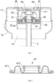
Fig. 1 is a schematic diagram of a local structure of an air spring assembly according to an embodiment of this invention. -
Fig. 2 is a schematic structural diagram of a sealing diaphragm according to an embodiment of this invention. - In the drawings:
- 11. First housing; 111. Mounting cavity; 12. Second housing; 13. Compression chamber;
- 2. Piston rod;
- 31. Inner core; 32. Rubber block;
- 41. Sealing diaphragm; 411. First anti-dropping protrusion; 412. Second anti-dropping protrusion; 42. Pressing block; 43. Sleeve; 44. Outer casing pipe; 45. Locking nut; 46. Limit plate.
- As shown in
Fig. 1 and Fig. 2 , this embodiment provides an air spring assembly, including a housing, apiston rod 2, and an upper suspension. The housing includes afirst housing 11 and asecond housing 12 in sealing connection with thefirst housing 11 to form acompression chamber 13. Thecompression chamber 13 is filled with compressed air. - An end of the
piston rod 2 penetrates the housing and is connected with the upper suspension. A sealing assembly is sleeved on thepiston rod 2, and is sandwiched between the upper suspension and an outer wall of the housing, to make the upper suspension to not be always in contact with the compressed air inside the housing during an axial movement of thepiston rod 2. In this embodiment, a mountingcavity 111 is provided, in a recessed manner, in the outer wall of thefirst housing 11, and the upper suspension and the sealing assembly are arranged in the mountingcavity 111. - In this embodiment, the upper suspension is arranged outside the housing. By using the sealing assembly, the upper suspension is always not in contact with the compressed air inside the housing during the axial movement of the
piston rod 2. In this way, not only the durability of the upper suspension is guaranteed, but also the dynamic rigidity and static rigidity of the upper suspension are reduced to a certain extent. In addition, a space occupation of the air spring assembly is reduced as much as possible by arranging the upper suspension and the sealing assembly in the mountingcavity 111 formed in the outer wall of the housing in the recessed manner. - In some embodiments, the sealing assembly includes a sealing
diaphragm 41, asleeve 43, and apressing block 42 which are sleeved outside thepiston rod 2. Firstanti-dropping protrusions 411 are protruded from both sides on the outer edge of the sealingdiaphragm 41. First positioning holes in inserting connection with the corresponding firstanti-dropping protrusion 411 are provided in positions of thepressing block 42 and the outer wall of the housing directly facing the firstanti-dropping protrusions 411. By using the firstanti-dropping protrusions 411 and the first positioning holes for positioning, assembly positioning between the sealingdiaphragm 41 and thepressing block 42 or the housing is guaranteed, and the outer edge of the sealingdiaphragm 41 is prevented from separating from thepressing block 42 and the outer wall of the housing. In other embodiments, the firstanti-dropping protrusion 411 may only be arranged on one side of the outer edge, but a sealing effect between thepressing block 42 and the outer wall of the housing is reduced accordingly. - Optionally, the first
anti-dropping protrusion 411 is a triangular structure. Through such a mode, desirable contact between the sealingdiaphragm 41 and thepressing block 42, between the sealingdiaphragm 41 and the outer wall of the housing may be guaranteed, so that the sealing effect between thepressing block 42 and the outer wall of the housing is guaranteed. - In this embodiment, the outer wall of the
piston rod 2 is provided with a first step surface. An inner hole of thesleeve 43 is a step hole. A second step surface is formed between a large diameter hole and a small diameter hole of the step hole. An end of thesleeve 43 abuts against the upper suspension to make the first step surface to abut against the second step surface. An inner edge of the sealingdiaphragm 41 is sandwiched between the large diameter hole and the outer wall of thepiston rod 2. - In some embodiments, second
anti-dropping protrusions 412 are protruded from both sides on the inner edge of the sealingdiaphragm 41. Second positioning holes in inserting connection with the corresponding secondanti-dropping protrusions 412 are provided in positions of thesleeve 43 and the outer wall of thepiston rod 2 directly facing the secondanti-dropping protrusions 412. By using the secondanti-dropping protrusions 412 and the second positioning holes for positioning, assembly positioning between the sealingdiaphragm 41 and thepiston rod 2 or thesleeve 43 is guaranteed, and the inner edge of the sealingdiaphragm 41 is prevented from separating from thesleeve 43 and thepiston rod 2. In other embodiments, the secondanti-dropping protrusion 412 may alternatively only be arranged on one side of the inner edge, but a sealing effect between thesleeve 43 and thepiston rod 2 is reduced accordingly. - Optionally, the second
anti-dropping protrusion 412 is a triangular structure. Through such a mode, desirable contact between the sealingdiaphragm 41 and thesleeve 43 or thepiston rod 2 may be guaranteed, so that the sealing effect between thesleeve 43 and thepiston rod 2 is guaranteed. - The upper suspension abuts against the
pressing block 42, to cause the outer edge of the sealingdiaphragm 41 to be sandwiched between thepressing block 42 and the outer wall of the housing. The upper suspension causes thesleeve 43 to abut against the outer wall of thepiston rod 2, and makes the inner edge of the sealingdiaphragm 41 to be sandwiched between an inner wall of thesleeve 43 and the outer wall of thepiston rod 2. - Optionally, the sealing assembly further includes a
limit plate 46 and a lockingnut 45. Thelimit plate 46 is fixedly arranged at an opening of the mountingcavity 111, to limit the upper suspension between thelimit plate 46 and thepressing block 42. The lockingnut 45 is threadedly connected with thepiston rod 2. The upper suspension is sandwiched between thesleeve 43 and the lockingnut 45. - In this embodiment, the upper suspension is mainly configured to achieve shock absorption, and includes an
inner core 31 and arubber block 32 provided outside theinner core 31 in a sleeving manner. Therubber block 32 and theinner core 31 are formed into an integrated structure through vulcanization. Therubber block 32 is in interference fit with an inner wall of the mountingcavity 111. In some embodiments, a positioning tab is protruded from an outer peripheral wall of therubber block 32. A groove in interference fit with the positioning tab is recessed in an inner peripheral wall of the mountingcavity 111. - In some embodiments, the sealing assembly further includes an outer casing pipe 44 sleeved outside the
rubber block 32. The outer casing pipe 44 is in interference fit with the inner peripheral wall of the mountingcavity 111. A first end of the outer casing pipe 44 abuts against thepressing block 42, and a second end of the outer casing pipe 44 abuts against the positioning tab of therubber block 32. Therubber block 32, the outer casing pipe 44, thepressing block 42, and an inner bottom wall of the mountingcavity 111 successively abut with each other, so that the outer edge of the sealingdiaphragm 41 is sandwiched between thepressing block 42 and the inner bottom wall of the mountingcavity 111. - In some embodiments, the
piston rod 2 is movable axially. In order to provide enough movable space for the axial movement of thepiston rod 2, in this embodiment, the sealingdiaphragm 41 is a structure that is formed by using an omega-shaped structure as a cross section to rotate 360° around a central axis of the sealing diaphragm. During the axial movement of thepiston rod 2, thesleeve 43, theinner core 31, and the lockingnut 45 are synchronously moved with thepiston rod 2. A shape of the sealingdiaphragm 41 is changed with the pulling or pushing of thepiston rod 2, and therubber block 32 is deformed accordingly. In addition, the inner edge of the sealingdiaphragm 41 is sandwiched between thesleeve 43 and the outer wall of thepiston rod 2, and the outer edge of the sealingdiaphragm 41 is sandwiched between thepressing block 42 and the outer wall of the housing. Therefore, the upper suspension can be guaranteed to not be in contact with the compressed air inside the housing. - In some embodiments, a smooth transition connection is achieved between the sealing
diaphragm 41 and thepressing block 42, and a smooth transition connection is achieved between the sealingdiaphragm 41 and thesleeve 43. Through the arrangement to limit the deformation of the sealingdiaphragm 41, the sealingdiaphragm 41 is prevented from breaking due to stress concentration caused by excessive curvature. - In an embodiment, the smooth transition connection may only be achieved between the sealing
diaphragm 41 and thepressing block 42, or the smooth transition connection may only be achieved between the sealingdiaphragm 41 and thesleeve 43. - In some embodiments, the smooth transition connection is achieved between the
pressing block 42 and the housing, to cause thepressing block 42 to be tightly attached to the housing, so that the stability of thepressing block 42 is guaranteed. - In this invention, the upper suspension is arranged outside the housing. By using the sealing assembly, the upper suspension is always not in contact with the compressed air inside the housing during the axial movement of the
piston rod 2. In this way, not only the durability of the upper suspension can be guaranteed, but also the dynamic rigidity and static rigidity of the upper suspension can be reduced to a certain extent. In addition, the space occupation of the air spring assembly is reduced as much as possible by arranging the upper suspension and the sealing assembly in the mountingcavity 111 formed in the outer wall of the housing in the recessed manner. - In the description of this invention, it is to be noted that, terms such as "center", "up", "down", "left", "right", "vertical", "horizontal", "inside", "outside", and the like are orientation or position relationships shown in the drawings, are adopted not to indicate or imply that indicated apparatuses or components must be in specific orientations or structured and operated in specific orientations but only to conveniently describe this invention and simplify descriptions, and thus should not be construed as limits to this invention. In addition, terms "first" and "second" are used for description only and should not be construed to indicate or imply relative importance. Terms "first position" and "second position" are two different positions.
- In the description of this invention, it is to be noted that, unless otherwise clearly specified and limited, the terms "mounted", "connected" and "connect" should be interpreted broadly. For example, the term "connect" may be fixed connection, detachable connection or integral construction. As an alternative, the term "connect" may be mechanical connection, or electrical connection. As an alternative, the term "connect" may be direct connection, or indirect connection through a medium, or communication in two elements. For those of ordinary skill in the art, specific meanings of the above mentioned terms in this invention may be understood according to a specific condition.
Claims (10)
- An air spring assembly, comprising a housing, a piston rod (2), and an upper suspension, wherein an end of the piston rod (2) penetrates the housing and is connected with the upper suspension; a sealing assembly is sleeved on the piston rod (2), and is sandwiched between the upper suspension and an outer wall of the housing, to cause the upper suspension to not be always in contact with compressed air inside the housing during an axial movement of the piston rod (2); anda mounting cavity (111) is provided, in a recessed manner, in the outer wall of the housing, andthe upper suspension and the sealing assembly are arranged in the mounting cavity (111).
- The air spring assembly according to claim 1, wherein the sealing assembly comprises a sealing diaphragm (41), a sleeve (43), and a pressing block (42) which are sleeved outside the piston rod (2); the upper suspension abuts against the pressing block (42), to cause an outer edge of the sealing diaphragm (41) to be sandwiched between the pressing block (42) and the outer wall of the housing; and the upper suspension makes the sleeve (43) to abut against an outer wall of the piston rod (2), to make an inner edge of the sealing diaphragm (41) to be sandwiched between an inner wall of the sleeve (43) and the outer wall of the piston rod (2).
- The air spring assembly according to claim 2, wherein the outer wall of the piston rod (2) is provided with a first step surface, and the sleeve (43) is sandwiched between the upper suspension and the first step surface.
- The air spring assembly according to claim 2, wherein the sealing assembly further comprises an outer casing pipe (44) in interference fit with the mounting cavity (111), and an end of the outer casing pipe (44) abuts against the pressing block (42).
- The air spring assembly according to claim 2, wherein a first anti-dropping protrusion (411) is protruded from at least one side on the outer edge of the sealing diaphragm (41); and a first positioning hole in inserting connection with the first anti-dropping protrusion (411) is provided in a position of at least one of the pressing block (42) and the outer wall of the housing directly facing the first anti-dropping protrusion (411).
- The air spring assembly according to claim 2, wherein a second anti-dropping protrusion (412) is protruded from at least one side on the inner edge of the sealing diaphragm (41); and a second positioning hole in inserting connection with the second anti-dropping protrusion (412) is provided in a position of at least one of the sleeve (43) and the outer wall of the piston rod (2) directly facing the second anti-dropping protrusion (412).
- The air spring assembly according to claim 2, wherein the sealing assembly further comprises:a limit plate (46), fixedly arranged at an opening of the mounting cavity (111), to limit the upper suspension between the limit plate (46) and the pressing block (42); anda locking nut (45), threadedly connected with the piston rod (2), the upper suspension being sandwiched between the sleeve (43) and the locking nut (45).
- The air spring assembly according to claim 2, wherein the piston rod (2) is movable axially, and the sealing diaphragm (41) is a structure that is formed by using an omega-shaped structure as a cross section to rotate 360° around a central axis of the sealing diaphragm (41).
- The air spring assembly according to claim 2, further comprising at least one of the following characteristics:a smooth transition connection is achieved between the sealing diaphragm (41) and the pressing block (42); ora smooth transition connection is achieved between the sealing diaphragm (41) and the sleeve (43).
- The air spring assembly according to claim 1, wherein the housing comprises a first housing (11) and a second housing (12) in sealing connection with the first housing (11) to form a compression chamber (13), and the mounting cavity (111) is formed, in the recessed manner, in an outer wall of the first housing (11).
Applications Claiming Priority (2)
| Application Number | Priority Date | Filing Date | Title |
|---|---|---|---|
| CN202010450562.1A CN111795098B (en) | 2020-05-25 | 2020-05-25 | an air spring assembly |
| PCT/CN2021/094164 WO2021238707A1 (en) | 2020-05-25 | 2021-05-17 | Air spring assembly |
Publications (2)
| Publication Number | Publication Date |
|---|---|
| EP4160044A1 true EP4160044A1 (en) | 2023-04-05 |
| EP4160044A4 EP4160044A4 (en) | 2024-07-17 |
Family
ID=72805944
Family Applications (1)
| Application Number | Title | Priority Date | Filing Date |
|---|---|---|---|
| EP21811951.9A Pending EP4160044A4 (en) | 2020-05-25 | 2021-05-17 | AIR SPRING ARRANGEMENT |
Country Status (3)
| Country | Link |
|---|---|
| EP (1) | EP4160044A4 (en) |
| CN (1) | CN111795098B (en) |
| WO (1) | WO2021238707A1 (en) |
Families Citing this family (4)
| Publication number | Priority date | Publication date | Assignee | Title |
|---|---|---|---|---|
| CN111795098B (en) * | 2020-05-25 | 2021-11-02 | 中国第一汽车股份有限公司 | an air spring assembly |
| CN112727993A (en) * | 2020-12-24 | 2021-04-30 | 上海保隆汽车科技(安徽)有限公司 | Air spring shock absorber with sealing diaphragm |
| CN113062945B (en) * | 2021-04-30 | 2022-12-23 | 济南弋泽展特机械有限公司 | Air spring shock absorber length adjusting valve |
| CN115370690A (en) * | 2022-08-03 | 2022-11-22 | 安徽红桥金属制造有限公司 | A diaphragm air spring cylinder |
Family Cites Families (21)
| Publication number | Priority date | Publication date | Assignee | Title |
|---|---|---|---|---|
| JPH0444904Y2 (en) * | 1985-02-26 | 1992-10-22 | ||
| IT1224466B (en) * | 1988-10-04 | 1990-10-04 | Fiat Auto Spa | VEHICLE SUSPENSION DEVICE INCLUDING A TELESCOPIC SHOCK ABSORBER AND AN AIR SPRING |
| DE19959839A1 (en) * | 1998-12-14 | 2000-07-06 | Mannesmann Sachs Ag | Pneumatic spring with vibration damper for motor vehicle has connecting bearing installed in region of generated surface of cylinder tube and is circular in construction and equipped with sealing ring sealing off spring chamber |
| DE10132061A1 (en) * | 2001-07-05 | 2003-01-16 | Phoenix Ag | Air spring arrangement |
| US20070093096A1 (en) * | 2005-10-21 | 2007-04-26 | Dt Swiss Inc. | Spring system, in particular for bicycles |
| CN2874127Y (en) * | 2005-11-23 | 2007-02-28 | 贵州前进橡胶有限公司 | Composite shock reducing rubber air spring assembly for automobile |
| DE102006032208B3 (en) * | 2006-07-12 | 2008-02-21 | Zf Friedrichshafen Ag | Air spring with vibration damper |
| IT1402803B1 (en) * | 2010-10-19 | 2013-09-18 | Cultraro | LINEAR SHOCK ABSORBER WITH COMPENSATING MEMBRANE WITH INTEGRATED GASKETS |
| DE102012220317B4 (en) * | 2011-11-15 | 2023-10-05 | Continental Automotive Technologies GmbH | Air spring |
| WO2016022539A1 (en) * | 2014-08-04 | 2016-02-11 | Firestone Industrial Products Company, Llc | Support and carrier assemblies as well as end member assemblies and gas spring and damper assemblies including same |
| DE102014016004B4 (en) * | 2014-10-28 | 2016-10-27 | Anvis Deutschland Gmbh | Thrust bearing for a pressurized shock absorber |
| CN104534007B (en) * | 2015-01-07 | 2016-06-08 | 青岛思锐科技有限公司 | Altitude valve built-in air spring cushion assembly |
| DE102015100281A1 (en) * | 2015-01-09 | 2016-07-14 | Trelleborgvibracoustic Gmbh | Composite component and air spring component with such a composite component |
| DE102015007743B4 (en) * | 2015-06-17 | 2018-02-15 | Anvis Deutschland Gmbh | Thrust bearing and pneumatic shock absorber |
| US10618366B2 (en) * | 2016-07-08 | 2020-04-14 | Continental Automotive Systems, Inc. | Vehicle air strut with twist lock closure cover |
| KR102522291B1 (en) * | 2016-12-13 | 2023-04-18 | 현대모비스 주식회사 | Suspension apparatus for vehicle |
| DE102018204485A1 (en) * | 2017-07-07 | 2019-01-10 | Continental Teves Ag & Co. Ohg | Air strut with sealed cap |
| WO2019068790A1 (en) * | 2017-10-04 | 2019-04-11 | Continental Teves Ag & Co. Ohg | AIR SPRING LEG WITH A PLASTIC AIR SPRING COVER |
| CN209079573U (en) * | 2018-11-06 | 2019-07-09 | 广州汽车集团股份有限公司 | Damper, suspension and automobile |
| CN111795098B (en) * | 2020-05-25 | 2021-11-02 | 中国第一汽车股份有限公司 | an air spring assembly |
| CN112727993A (en) * | 2020-12-24 | 2021-04-30 | 上海保隆汽车科技(安徽)有限公司 | Air spring shock absorber with sealing diaphragm |
-
2020
- 2020-05-25 CN CN202010450562.1A patent/CN111795098B/en active Active
-
2021
- 2021-05-17 EP EP21811951.9A patent/EP4160044A4/en active Pending
- 2021-05-17 WO PCT/CN2021/094164 patent/WO2021238707A1/en not_active Ceased
Also Published As
| Publication number | Publication date |
|---|---|
| EP4160044A4 (en) | 2024-07-17 |
| CN111795098B (en) | 2021-11-02 |
| WO2021238707A1 (en) | 2021-12-02 |
| CN111795098A (en) | 2020-10-20 |
Similar Documents
| Publication | Publication Date | Title |
|---|---|---|
| EP4160044A1 (en) | Air spring assembly | |
| CN212657167U (en) | An automobile hydraulic bush and automobile front suspension | |
| JPS5912438Y2 (en) | hydraulic shock absorber | |
| US20030151177A1 (en) | Double rolling-lobe spring arrangement | |
| JP4955613B2 (en) | Front fork | |
| CN220668224U (en) | Adjustable shock absorber with axial sealing structure | |
| CN118912135A (en) | Double-valve parallel-arranged double external electromagnetic valve type electric control shock absorber | |
| CN114198452B (en) | Assembly method of oil seal guide assembly | |
| CN205956285U (en) | Oil gas shock absorber | |
| JPS6035810Y2 (en) | suspension system | |
| CN209079573U (en) | Damper, suspension and automobile | |
| CN217582972U (en) | High-pressure output single-tube bushing | |
| CN223806538U (en) | An integrated intermediate cylinder structure and a dual-valve electronically controlled vibration damper | |
| CN207579577U (en) | Engine Mounting System | |
| CN216691977U (en) | Piston assembly for air spring, air spring and vehicle | |
| CN220523179U (en) | Novel automobile shock pad structure | |
| CN215661935U (en) | Jig for pressing rubber bushing into product | |
| CN219932816U (en) | Automobile shock absorber | |
| CN223152442U (en) | Triaxial cylinder | |
| CN120819597B (en) | An air spring | |
| CN218992200U (en) | Piston valve for shock absorber, shock absorber and vehicle | |
| CN215634648U (en) | Shock absorber of electric vehicle | |
| CN223411345U (en) | Air spring top cover assembly for suspension device and suspension device | |
| CN216343619U (en) | High-performance shock absorber with air spring | |
| JP5013775B2 (en) | Stopper device |
Legal Events
| Date | Code | Title | Description |
|---|---|---|---|
| STAA | Information on the status of an ep patent application or granted ep patent |
Free format text: STATUS: THE INTERNATIONAL PUBLICATION HAS BEEN MADE |
|
| PUAI | Public reference made under article 153(3) epc to a published international application that has entered the european phase |
Free format text: ORIGINAL CODE: 0009012 |
|
| STAA | Information on the status of an ep patent application or granted ep patent |
Free format text: STATUS: REQUEST FOR EXAMINATION WAS MADE |
|
| 17P | Request for examination filed |
Effective date: 20221223 |
|
| AK | Designated contracting states |
Kind code of ref document: A1 Designated state(s): AL AT BE BG CH CY CZ DE DK EE ES FI FR GB GR HR HU IE IS IT LI LT LU LV MC MK MT NL NO PL PT RO RS SE SI SK SM TR |
|
| DAV | Request for validation of the european patent (deleted) | ||
| DAX | Request for extension of the european patent (deleted) | ||
| REG | Reference to a national code |
Ref country code: DE Ref legal event code: R079 Free format text: PREVIOUS MAIN CLASS: F16F0009020000 Ipc: F16F0009540000 |
|
| A4 | Supplementary search report drawn up and despatched |
Effective date: 20240618 |
|
| RIC1 | Information provided on ipc code assigned before grant |
Ipc: B60G 13/00 20060101ALN20240612BHEP Ipc: B60G 15/12 20060101ALI20240612BHEP Ipc: F16F 9/36 20060101ALI20240612BHEP Ipc: F16F 9/54 20060101AFI20240612BHEP |