EP4160025A1 - Accumulator assembly - Google Patents
Accumulator assembly Download PDFInfo
- Publication number
- EP4160025A1 EP4160025A1 EP22194144.6A EP22194144A EP4160025A1 EP 4160025 A1 EP4160025 A1 EP 4160025A1 EP 22194144 A EP22194144 A EP 22194144A EP 4160025 A1 EP4160025 A1 EP 4160025A1
- Authority
- EP
- European Patent Office
- Prior art keywords
- chamber
- accumulator
- gas chamber
- piston
- housing
- Prior art date
- Legal status (The legal status is an assumption and is not a legal conclusion. Google has not performed a legal analysis and makes no representation as to the accuracy of the status listed.)
- Granted
Links
Images




Classifications
-
- F—MECHANICAL ENGINEERING; LIGHTING; HEATING; WEAPONS; BLASTING
- F15—FLUID-PRESSURE ACTUATORS; HYDRAULICS OR PNEUMATICS IN GENERAL
- F15B—SYSTEMS ACTING BY MEANS OF FLUIDS IN GENERAL; FLUID-PRESSURE ACTUATORS, e.g. SERVOMOTORS; DETAILS OF FLUID-PRESSURE SYSTEMS, NOT OTHERWISE PROVIDED FOR
- F15B1/00—Installations or systems with accumulators; Supply reservoir or sump assemblies
- F15B1/02—Installations or systems with accumulators
- F15B1/04—Accumulators
-
- F—MECHANICAL ENGINEERING; LIGHTING; HEATING; WEAPONS; BLASTING
- F15—FLUID-PRESSURE ACTUATORS; HYDRAULICS OR PNEUMATICS IN GENERAL
- F15B—SYSTEMS ACTING BY MEANS OF FLUIDS IN GENERAL; FLUID-PRESSURE ACTUATORS, e.g. SERVOMOTORS; DETAILS OF FLUID-PRESSURE SYSTEMS, NOT OTHERWISE PROVIDED FOR
- F15B1/00—Installations or systems with accumulators; Supply reservoir or sump assemblies
- F15B1/02—Installations or systems with accumulators
- F15B1/04—Accumulators
- F15B1/08—Accumulators using a gas cushion; Gas charging devices; Indicators or floats therefor
- F15B1/24—Accumulators using a gas cushion; Gas charging devices; Indicators or floats therefor with rigid separating means, e.g. pistons
-
- F—MECHANICAL ENGINEERING; LIGHTING; HEATING; WEAPONS; BLASTING
- F15—FLUID-PRESSURE ACTUATORS; HYDRAULICS OR PNEUMATICS IN GENERAL
- F15B—SYSTEMS ACTING BY MEANS OF FLUIDS IN GENERAL; FLUID-PRESSURE ACTUATORS, e.g. SERVOMOTORS; DETAILS OF FLUID-PRESSURE SYSTEMS, NOT OTHERWISE PROVIDED FOR
- F15B15/00—Fluid-actuated devices for displacing a member from one position to another; Gearing associated therewith
- F15B15/08—Characterised by the construction of the motor unit
- F15B15/14—Characterised by the construction of the motor unit of the straight-cylinder type
-
- F—MECHANICAL ENGINEERING; LIGHTING; HEATING; WEAPONS; BLASTING
- F15—FLUID-PRESSURE ACTUATORS; HYDRAULICS OR PNEUMATICS IN GENERAL
- F15B—SYSTEMS ACTING BY MEANS OF FLUIDS IN GENERAL; FLUID-PRESSURE ACTUATORS, e.g. SERVOMOTORS; DETAILS OF FLUID-PRESSURE SYSTEMS, NOT OTHERWISE PROVIDED FOR
- F15B2201/00—Accumulators
- F15B2201/20—Accumulator cushioning means
- F15B2201/205—Accumulator cushioning means using gas
-
- F—MECHANICAL ENGINEERING; LIGHTING; HEATING; WEAPONS; BLASTING
- F15—FLUID-PRESSURE ACTUATORS; HYDRAULICS OR PNEUMATICS IN GENERAL
- F15B—SYSTEMS ACTING BY MEANS OF FLUIDS IN GENERAL; FLUID-PRESSURE ACTUATORS, e.g. SERVOMOTORS; DETAILS OF FLUID-PRESSURE SYSTEMS, NOT OTHERWISE PROVIDED FOR
- F15B2201/00—Accumulators
- F15B2201/30—Accumulator separating means
- F15B2201/31—Accumulator separating means having rigid separating means, e.g. pistons
-
- F—MECHANICAL ENGINEERING; LIGHTING; HEATING; WEAPONS; BLASTING
- F15—FLUID-PRESSURE ACTUATORS; HYDRAULICS OR PNEUMATICS IN GENERAL
- F15B—SYSTEMS ACTING BY MEANS OF FLUIDS IN GENERAL; FLUID-PRESSURE ACTUATORS, e.g. SERVOMOTORS; DETAILS OF FLUID-PRESSURE SYSTEMS, NOT OTHERWISE PROVIDED FOR
- F15B2201/00—Accumulators
- F15B2201/30—Accumulator separating means
- F15B2201/32—Accumulator separating means having multiple separating means, e.g. with an auxiliary piston sliding within a main piston, multiple membranes or combinations thereof
-
- F—MECHANICAL ENGINEERING; LIGHTING; HEATING; WEAPONS; BLASTING
- F15—FLUID-PRESSURE ACTUATORS; HYDRAULICS OR PNEUMATICS IN GENERAL
- F15B—SYSTEMS ACTING BY MEANS OF FLUIDS IN GENERAL; FLUID-PRESSURE ACTUATORS, e.g. SERVOMOTORS; DETAILS OF FLUID-PRESSURE SYSTEMS, NOT OTHERWISE PROVIDED FOR
- F15B2201/00—Accumulators
- F15B2201/40—Constructional details of accumulators not otherwise provided for
- F15B2201/415—Gas ports
- F15B2201/4155—Gas ports having valve means
-
- Y—GENERAL TAGGING OF NEW TECHNOLOGICAL DEVELOPMENTS; GENERAL TAGGING OF CROSS-SECTIONAL TECHNOLOGIES SPANNING OVER SEVERAL SECTIONS OF THE IPC; TECHNICAL SUBJECTS COVERED BY FORMER USPC CROSS-REFERENCE ART COLLECTIONS [XRACs] AND DIGESTS
- Y02—TECHNOLOGIES OR APPLICATIONS FOR MITIGATION OR ADAPTATION AGAINST CLIMATE CHANGE
- Y02E—REDUCTION OF GREENHOUSE GAS [GHG] EMISSIONS, RELATED TO ENERGY GENERATION, TRANSMISSION OR DISTRIBUTION
- Y02E60/00—Enabling technologies; Technologies with a potential or indirect contribution to GHG emissions mitigation
- Y02E60/16—Mechanical energy storage, e.g. flywheels or pressurised fluids
Definitions
- the present disclosure relates generally to an accumulator assembly for a hydraulic system and more specifically to an accumulator assembly having two separate gas chambers.
- a typical accumulator for a hydraulic system only has one gas chamber which limits the accumulator to one pre-charge pressure and one initial gas volume. This limits the standard accumulator's effectiveness over large pressure ranges. For example, in the typical accumulator the gas volume becomes substantially reduced as the pressure in the hydraulic system increases. Once the gas volume is substantially reduced, the standard accumulator will not be able to absorb much more oil. This leads to larger sized accumulators used to address large pressure range applications or a reduction in performance among other things.
- One embodiment is an accumulator assembly that has an oil chamber, a first piston separating a first gas chamber from the oil chamber, and a second piston separating a second gas chamber from the oil chamber.
- the first and second piston are independently movable to alter the volume of the oil chamber.
- the first gas chamber is configured to provide a first pre-charge pressure and the second gas chamber is configured to provide a second pre-charge pressure, the second pre-charge pressure being different than the first pre-charge pressure.
- One aspect of this example includes a valve coupled to at least one of the first gas chamber or the second gas chamber, wherein the valve is configured to be coupled to a pressure source to alter the corresponding first or second pre-charge pressure.
- One aspect of this example has a first valve coupled to the first gas chamber and a second valve coupled to the second gas chamber. In part of this aspect, the first valve and the second valve are each coupleable to a pressure source to independently alter the corresponding first or second pre-charge pressure.
- Another example of this embodiment has a fluid passage fluidly coupling the oil chamber to a chamber of a hydraulic cylinder assembly.
- the first piston and second piston are configured to move coaxially along an accumulator axis in opposite directions as the volume of the oil chamber changes.
- first gas chamber, second gas chamber, and oil chamber are defined within a housing.
- first gas chamber and second gas chamber are defined in an accumulator borehole of the housing having a consistent diameter through first gas chamber and the second gas chamber.
- Another part of this example has a hydraulic borehole defined in the housing and configured to at least partially receive a hydraulic cylinder assembly.
- a fluid passage is defined in the housing wherein the fluid passage fluidly couples the oil chamber to the hydraulic borehole.
- an end cap is selectively coupled to the housing to seal at least one of the first gas chamber or the second gas chamber.
- an end cap is selectively coupled to the housing to seal one end of the hydraulic borehole from the surrounding environment and to fluidly seal at least one of the first gas chamber or the second gas chamber.
- the end cap has an actuator coupler defined therein.
- the end cap is selectively coupled to the housing with one or more fastener.
- Another embodiment of this disclosure is an accumulator assembly that has an oil chamber configured to have a variable oil chamber volume, a first gas chamber configured to have a variable first volume and to contain a first pre-charge pressure, and a second gas chamber configured to have a variable second volume and a second pre-charge pressure. The first pre-charge pressure and the second pre-charge pressure are independently adjustable.
- the first gas chamber comprises a piston separating the oil chamber and the first gas chamber and the second gas chamber comprises a diaphragm separating the oil chamber from the second gas chamber.
- a hydraulic cylinder assembly having a rod, wherein at least one of the first gas chamber and the second gas chamber are defined within, or radially about the rod.
- Yet another embodiment of this disclosure is a method of manufacturing an accumulator assembly.
- the method includes creating an accumulator borehole through a housing, creating a hydraulic borehole through the housing, creating a fluid passage through the housing fluidly coupling at least a portion of the hydraulic borehole with the accumulator bore, positioning a first piston and a second piston in the accumulator borehole to define an oil chamber between the first and second piston, the oil chamber fluidly coupled to the fluid passage, positioning a rod having a rod piston in the hydraulic borehole, and coupling an end cap to the housing to retain the corresponding first and second piston in the accumulator borehole and the rod piston in the hydraulic borehole.
- fluid applied to the rod piston at a pressure is directed to the oil chamber through the fluid passage and the first and second piston are movable within the accumulator borehole away from one another to increase a volume of the oil chamber.
- FIG. 1 a schematic view of a typical hydraulic configuration 100 is illustrated.
- This configuration has a fluid source 102 that provides fluid, such as hydraulic oil, to a pump 104 that pumps the fluid to provide a pressure and flow of the fluid to conduit 106.
- the conduit 106 may redirect the pressurized fluid to many different hydraulic components such as valve assemblies, actuators, motors, and the like to provide hydraulic power (i.e., fluid at a pressure and flow) thereto.
- the conduit 106 may fluidly couple a valve assembly 108 to the pump 104.
- This exemplary valve assembly 108 may be a four port, three-position valve that selectively provides pressurized fluid to a hydraulic cylinder assembly 110 to selectively extend, retract, or maintain the linear displacement of the hydraulic cylinder assembly 110.
- this is only one example of a valve assembly and many other type of valve assemblies are considered herein.
- the hydraulic cylinder assembly 110 may have a rod 118 coupled to a piston 120 within a cylinder 122 that separates an extension chamber 124 and a retraction chamber 126.
- the chambers 124, 126 may be defined within the cylinder 122 such that a pressure offset between the chambers 124, 126 may cause the piston 120 and corresponding rod 118 to move linearly towards the low pressure chamber (assuming minimal external forces are acting on the rod 118).
- the piston 120 and rod 118 may move in an extended direction 128.
- the piston 120 and rod 118 may move in a retracted direction 130. Further, if fluid is restricted from entering or leaving the chambers 124, 126, the rod 118 and piston 120 may remain in substantially the same location within the cylinder 122.
- the valve assembly 108 may be configured to be selectively moved between a first position 112, a second position 114, and a third position 116.
- the first position 112 routes the conduit 106 from the pump 104 back to the fluid source 102 or to other components of the hydraulic system and isolates fluid in in the chambers 124, 126 to thereby substantially lock the rod 118 and piston 120.
- pressurized fluid may be directed to the extension chamber 124 while the retraction chamber 126 is vented or otherwise directed to a low pressure reservoir to extend the rod 118 and piston 120 in the extended direction 128.
- pressurized fluid may be directed to the retraction chamber 126 while the extension chamber 124 is vented or otherwise directed to a low pressure reservoir to move the rod 118 and piston 120 in the retracted direction 128.
- the valve assembly 108 may be selectively controlled electronically as part of an electro-hydraulic system or may be manually manipulated among other methods.
- an accumulator 132 may be fluidly coupled to conduit 134 fluidly coupling the valve assembly 108 to the hydraulic actuator 110.
- the accumulator 132 may be coupled to the conduit 134 fluidly coupled to the extension chamber 124, however, other examples may position the accumulator 132 on conduit 136 fluidly coupled to the retraction chamber 126.
- the accumulator 132 may provide a gas chamber 138 that is separated from the fluid in the conduit 134 by a diaphragm or piston 140.
- the diaphragm or piston 140 may be repositioned to accommodate additional, or less, fluid in the accumulator 132 by altering the volume of the gas chamber 138.
- the accumulator has a single gas chamber 138 and once the diaphragm or piston 140 substantially expands, the accumulator 132 may not be able to absorb much more fluid from the conduit 134 or extension chamber 124. Further, the accumulator 132 has a single gas chamber 138 and therefore is only capable of providing a single pre-charge pressure. As such, the accumulator 132 may not be able to accommodate wide-range pressure variations.
- the accumulator assembly 200 may have an accumulator 201 that provides gas chambers that are compressible to address pressure variations in a hydraulic system. More specifically, the accumulator 201 of the accumulator assembly 200 may provide a first gas chamber 202 and a second gas chamber 204 that may provide different pre-charge pressures therein.
- Pre-charge pressure refers to the pressure of the gas within the corresponding chambers 202, 204 when the corresponding hydraulic assembly is not providing a substantial pressure. In other words, pre-charge pressure may refer to the pressure in the corresponding chambers 202, 204 when the system is in a neutral state (i.e., not providing substantial pressure to an oil chamber 206 of the accumulator 201).
- the first gas chamber 202 may be separated from the oil chamber 206 by a first piston 208 and the second gas chamber 204 may be separated from the oil chamber 206 by a second piston 210.
- the pistons 208, 210 may slide axially away from one another along an accumulator axis 212 to further compress any gases in the corresponding chambers 202, 204.
- one or both of the pistons 208, 210 extend away from the other along the accumulator axis 212 to accommodate more fluid in the oil chamber 208.
- a first valve 214 may be fluidly coupled to the first gas chamber 202 and a second valve 216 may be fluidly coupled to the second gas chamber 204.
- the first and second valves 214, 216 may provide a location for one or more pressure source 218 to selectively alter the pre-charge pressure of the corresponding chamber 202, 204.
- the pressure source 218 may be part of a pneumatic system of a work machine. Alternatively, it may be a manual pump that can be coupled to the corresponding valve 214, 216 to alter the pressure of the corresponding chamber 202, 204.
- an electropneumatic system may be coupled to the first and second gas chambers 202, 204 through the corresponding valves 214, 216 to selectively alter the pre-charge pressure therein.
- the first and second piston 208, 210 may slide axially along the accumulator axis 212 within an accumulator borehole 220 defined within a housing 222.
- the accumulator borehole 220 may be a substantially cylindrical bore through the housing 222. Further, the cylindrical walls of the accumulator borehole 220 may define a portion of the first gas chamber 202, the second gas chamber 204, and the oil chamber 206.
- the pistons 208, 210 may be correspondingly sized to fit within the accumulator borehole 220 and fluidly seal the oil chamber 206 from the corresponding first and second gas chambers 202, 204.
- the pistons 208, 210 may have one or more seal 224 positioned between the outer walls of the corresponding piston 208, 210 and the radial wall of the accumulator borehole 220 to fluidly seal the oil chamber 206 from the corresponding first and second gas chambers 202, 204.
- the accumulator borehole 220 may have a substantially consistent radius through the first gas chamber 202, oil chamber 206, and second gas chamber 204 to allow all of the chambers 202, 204, 206 to be partially formed in the same manufacturing step (i.e., drilling or otherwise forming the accumulator borehole 220 in the housing 222).
- a stop 270 may be formed in the housing 222 to ensure the first and second piston 208, 210 do not extend past the stop 270 to obstruct a fluid passage 258 to the oil chamber 206.
- the stop 270 may be formed by a radially inward section of the housing 222 defined about the location wherein the fluid passage 258 extends into the oil chamber 206.
- the stop 270 may be a C-clip for each piston 208, 210 that extends into corresponding grooves defined in the interior walls of the oil chamber 206 to substantially prevent the corresponding piston 208, 210 from extending into the oil chamber 206 to obstruct the fluid passage 258.
- the housing 222 may have an end cap 226, 228 coupled to opposing sides of the housing 222 to substantially fluidly isolate the corresponding gas chambers 202, 204 from a surrounding environment 230.
- the first gas chamber 202 may be defined by the cylindrical wall of the accumulator borehole 220 through the housing 222, the first piston 208, and the end cap 226.
- the second gas chamber 204 may be defined by the cylindrical wall of the accumulator borehole 220 through the housing 222, the second piston 210, and the end cap 228.
- Each piston 208, 210 may have piston cavity 232 defined therein.
- the piston cavity 232 may be a cavity defined in the corresponding piston 208, 210 sized to allow any protruding elements of the corresponding valves 214, 216 to be partially positioned therein when the corresponding piston 208, 210 is in, or about in, a fully extended position.
- the fully extended position may be the position wherein the corresponding piston 208, 210 is as close as possible to the corresponding end cap 226, 228 thereby maximizing the volume of the oil chamber 206.
- the piston cavity 232 may ensure that the corresponding piston 208, 210 can become positioned in the fully extended position without substantially contacting or damaging any portion of the corresponding valve 214, 216.
- the accumulator assembly 200 may also have a hydraulic cylinder assembly 234 similar to the hydraulic cylinder assembly 110.
- the hydraulic cylinder assembly 234 is at least partially defined within a hydraulic borehole 236 in the same housing 222 as the accumulator 201.
- the hydraulic borehole 236 is defined through a portion of the housing 222 to accommodate a rod 238, rod piston 240, and seal 242 of the hydraulic cylinder assembly 234.
- the rod 238 and piston 240 may function in substantially the same way as discussed herein for the hydraulic cylinder assembly 110. That is, the rod piston 240 may fluidly separate an extension chamber 244 on one end of the hydraulic borehole 236 from a retraction chamber 246 on the other end. Further, hydraulic fluid may be selectively provided to, or removed from, the extension chamber 244 through an extension orifice 248. Similarly, hydraulic fluid may be selectively provided to, or removed from, the retraction chamber 246 through a retraction orifice 250.
- the extension orifice 248 and retraction orifice 250 may be fluidly coupled to a hydraulic system such as the valve assembly 108, pump 104, and fluid source 102 discussed herein to selectively move the rod 238 and rod piston 240 in an extension direction 252 or a retraction direction 254 along a rod axis 256.
- hydraulic cylinder assembly 234 may be coupled to movable components of a work machine or the like.
- the work machine may have an electro-hydraulic system that selectively controls the valve assembly 108 to alter the position of the rod 238 and rod piston 240 in the extension direction 252 or the retraction direction 254.
- the housing 222 may also define the fluid passage 258 therein that fluidly couples the extension chamber 244 to the oil chamber 206.
- the volume of the oil chamber 206 may increase as the pistons 208, 210 move axially away from one another and the gas in the corresponding chambers 202, 204 is further compressed.
- the housing 222 may provide a structural base for the accumulator 201 and the hydraulic cylinder assembly 234 while simultaneously providing a fluid passage 258 that fluidly couples the oil chamber 206 to the extension chamber 244.
- the end caps 226, 228 may also partially enclose the extension chamber 244 and retraction chamber 246 with the hydraulic borehole 236 of the housing 222. More specifically, the end caps 226, 228 may be positioned on axial ends of the hydraulic borehole 236 to substantially seal the interior of the borehole 236 from the surrounding environment 230. In one aspect of this disclosures, seals or the like may be positioned between the corresponding end caps 226, 228 and the housing 222 at each end of the accumulator and hydraulic borehole 220, 236 to assist with sealing the corresponding bores 220, 236. Further, the end caps 226, 228 may be removably coupled to the housing 222 with fasteners 260. More specifically, the housing 222 may have threaded holes to receive fasteners 260 such as screws to removably couple the end caps 226, 228 to the housing 222.
- an actuator coupler 262 may be formed in the end cap 226.
- the actuator coupler 262 may be a coupling location along the rod axis 256 that provides sufficient structural strength to couple the hydraulic cylinder assembly 234 to movable components of a work machine or the like.
- a rod coupler 264 may be coupled to a first movable component of a work machine and the actuator coupler 262 may be coupled to a second component of the work machine.
- the rod 238 may move in either the extension direction 252 or the retraction direction 254 to alter the orientation of the first movable component relative to the second component.
- the accumulator 201 may absorb pressure spikes caused by either the hydraulic system of the work machine or physical inputs on the rod 238 in the retraction direction 254.
- the hydraulic cylinder assembly 234 is described herein as formed within the same housing 222 as the accumulator 201, other embodiments considered herein separate the hydraulic assembly from the housing of the accumulator. More specifically, the accumulator 201 may substantially replace the accumulator 132 illustrated in Fig. 1 . In this configuration, the fluid passage 258 of the accumulator 201 may utilize conduit, hose, or the like to be routed to the extension chamber 124 of the hydraulic cylinder assembly 110.
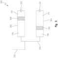
- an accumulator assembly 300 may provide two separate accumulators 302, 304 fluidly coupled to one another through conduit 306.
- the accumulators 302 may function in substantially similar ways as the accumulator 201 wherein pistons 308, 310 separate corresponding gas chambers 312, 314 from oil chambers 316, 318.
- the conduit 306 fluidly couples the separate oil chambers 316, 318 to one another and provides a coupling location 320 for the extension chamber 124 of the cylinder assembly 110.
- the gas chambers 312, 314 may also have valves 322, 324 that allow the gas chambers 312, 314 to be independently pressurized with different pressures similar to valves 214, 216 discussed herein.
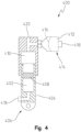
- Fig. 4 another embodiment of a dual-gas chamber accumulator assembly 400 is illustrated.
- the accumulator assembly 400 may define a first gas chamber 402 at least partially within a rod 404 of a hydraulic cylinder assembly 406. More specifically, the rod 404 may have a cylindrical cavity therein with a piston 408 positioned within the cylindrical cavity. The piston 408 may separate the first gas chamber 402 from an oil chamber 410.
- conduit may fluidly couple the oil chamber 410 to a diaphragm accumulator 414 having a second gas chamber 412 fluidly separated from the oil chamber 410 by a diaphragm 416.
- Both the first gas chamber 402 and the second gas chamber 412 may have valves 418 coupled thereto allow the pre-charge pressure in the corresponding gas chambers 402, 412 to be selectively altered as discussed herein with reference to valves 214, 216.
- fluid pressure may be provided to the oil chamber 410 at a fluid input 420 by a hydraulic system or the like.
- the rod 404 may extend or retract responsive to changes in the pressure of fluid provided at the fluid input 420 and the gas in the gas chambers 402, 412 may be compressed to modify the volume of the oil chamber 410 to address spikes or drops in the fluid pressure of the oil chamber 410 as discussed herein.
- the accumulator assembly 500 of Fig. 5 may have a first gas chamber 502 defined in an annular cavity around a cylinder 504 and rod 506 of a hydraulic cylinder assembly. This configuration may have an annular disk-shaped piston 510 that slides along a radially outer wall of the cylinder 504 to separate the first gas chamber 502 from an oil chamber 512.
- a diaphragm accumulator 514 having a second gas chamber 516 may be fluidly separated from the oil chamber 512 by a diaphragm 518.
- Both the first gas chamber 502 and the second gas chamber 516 may have valves 520 coupled thereto allow the pre-charge pressure in the corresponding gas chambers 502, 516 to be selectively altered as discussed herein with reference to valves 214, 216.
- a valve assembly 522 may be similar to valve assembly 108 and may selectively alter the pressure of fluid provided to the oil chamber 512 from a hydraulic system.
- the accumulator assembly 500 may address spikes or reductions in fluid pressure in the oil chamber 512 by modifying the volume of the oil chamber 512 through movement of the corresponding piston 510 and diaphragm 518.
- All embodiments of the dual gas chamber accumulator assembly discussed herein may provide separate gas chambers that can be independently filled to different pre-charge pressures. This may provide for a more compact accumulator assembly that can address a wider range of oil chamber pressure and volume change compared to single gas chamber accumulators.
- the first gas chamber may have a low pre-charge pressure while the second gas chamber may have a relatively high pre-charge pressure.
- the relatively low pre-charge pressure in the first chamber may be further compressed until the first gas chamber cannot be compressed much more while the volume of the second gas chamber remains unsubstantially changed.
- the second gas chamber may begin to compress the relatively high pre-charged gas chamber to further expand the volume of the oil chamber to accommodate the pressure spike in the oil chamber.
- a single piece of material may be provided for the housing 222.
- the accumulator borehole 220 may be created in the housing 222.
- the accumulator borehole 220 may be drilled or otherwise bored through the housing 222 along the accumulator axis 212.
- the borehole 220 may extend only to the stop 270 and be formed from either side of the housing 222.
- a smaller borehole may be defined through the stop 270 to form the oil chamber 206 therein.
- the stop 270 may extend substantially radially inward to contact and prevent the pistons 208, 210 from entering the oil chamber 206 and obstructing the fluid passage 258.
- the borehole 220 may be formed by a single drilling process wherein the entire borehole 220 is about the same radius.
- the stop 270 may be formed by a C-clip positioned in recesses formed on either side of the oil chamber 206. The C-clips may be sized to contact the corresponding pistons 208, 210 to prevent the pistons 208, 210 from entering the oil chamber 206 and obstructing the fluid passage 258 similarly to the stop 270.
- the hydraulic borehole 236 may be formed through the housing 222 via drilling or otherwise boring the hydraulic borehole 236 through the housing 222 along the rod axis 256.
- the hydraulic borehole 236 and the accumulator borehole 220 may be substantially parallel to one another through the housing 222.
- the fluid passage 258 may be formed in the housing in step 606 to provide a fluid pathway from the accumulator borehole 220 to the hydraulic borehole 236.
- the fluid passage 258 may be formed by a first partial through-hole 614 defined along a first passage axis 616.
- the first passage axis 616 may be substantially perpendicular to the accumulator axis 212 and the first partial through-hole 614 may be formed by a drilling process that extends through a wall of the accumulator borehole 220, through the accumulator borehole 220, and at least partially into a wall 622 of the housing 222 separating the accumulator borehole 220 and the hydraulic borehole 236.
- a plug 626 may be placed in the wall of the accumulator borehole 220 to substantially isolate the accumulator borehole 220 from the surrounding environment 230.
- a second partial through-hole 620 may also be formed through the wall 622 of the housing 222 along a second passage axis 618.
- the second passage axis 618 may be parallel with the accumulator axis 212 and perpendicular to the first passage axis 616.
- the second partial through-hole 620 may extend from one side of the housing 222 into the wall 622 until the second partial through-hole 620 at least partially intersects the first partial through-hole 614.
- a radial passage 624 may be formed at the entry point of the second partial through-hole 620 fluidly coupling the second partial through-hole 620 to the hydraulic borehole 236. In this configuration, once the end cap 226 is coupled to the housing 222, the fluid passage 258 may fluidly couple the extension chamber 244 to the oil chamber 206 as illustrated in Fig. 2b .
- the pistons 208, 210 may be positioned in the accumulator borehole 220 on opposing sides of the first partial through-hole 614 to partially define the oil chamber 206.
- Seals 224 may be positioned on the pistons 208, 210 prior to insertion into the accumulator borehole 220 and the pistons 208, 210 may be oriented so the piston cavities 232 are facing the corresponding valves 214, 216.
- the C-clips may be positioned within the borehole 220 prior to inserting the pistons 208, 210 to prevent the pistons 208, 210 from moving too far into the oil chamber 206 and blocking the fluid passage 258.
- the pistons 208, 210 will be prevented from blocking the fluid passage 258 through contract with the stop 270 formed from the housing 222.
- the rod 238 and rod piston 240 may be positioned within the hydraulic borehole 236 in box 610.
- the end caps 226, 228 may be coupled to the housing 222 to substantially lock the pistons 208, 210 and rod piston 240 within the corresponding boreholes 220, 236. Further, the end caps 226, 228 may have seals, gaskets, or the like to substantially prevent gas or fluid from escaping between the housing 222 and the corresponding end cap 226, 228. In one aspect of this disclosure, the end cap 228 may have the seal 242 for the hydraulic cylinder assembly 234 formed therein. Further, the fasteners 260 may be tightened to the housing 222 at the appropriate torque to ensure the end caps 226, 228 maintain the fluid-tight coupling to the housing 222. The valves 214, 216 may be coupled to the corresponding end caps 226, 228 either before the end caps 226, 228 are coupled to the housing 222 or afterwards in a separate step.
- the actuator coupler 262 and rod coupler 264 may be coupled to movable components of a work machine or the like. Further, a hydraulic system may be fluidly coupled to the orifices 248, 250 through a valve assembly to selectively actuate the hydraulic cylinder assembly 234.
- the accumulator assembly 200 is illustrated having an extension orifice 248 and retraction orifice 250 fluidly coupled to a hydraulic system to selectively move the rod 238 and rod piston 240 in an extension direction 252 or a retraction direction 254 along a rod axis 256.
- the fluid passage 258 is illustrated as fluidly coupling the extension chamber 244 to the oil chamber 206.
- this disclosure also contemplates routing the fluid passage 258 to the retraction chamber 246. In this configuration, when pressure spikes or the like are introduced to the fluid in the retraction chamber 246, the volume of the oil chamber 206 may increase as the pistons 208, 210 move axially away from one another and the gas in the corresponding chambers 202, 204 is further compressed.
- the fluid passage 258 can be routed to either the extension chamber 244 or the retraction chamber 246 to provide the benefits of the accumulator assembly 200 either while the extension chamber 244 is being pressurized or while the retraction chamber 246 is being pressurized.
- the hydraulic assembly illustrated in Fig. 2b may be a double acting cylinder
- the accumulator assembly 200 may be applied to a single acting cylinder assembly.
- a single acting extension hydraulic cylinder may route the fluid passage 258 to the extension chamber 244.
- a single acting retraction cylinders may route the fluid passage 258 to the retraction chamber 246.
- the accumulator assembly 200 contemplated herein can be applied to any hydraulic cylinder configuration.
Landscapes
- Engineering & Computer Science (AREA)
- Physics & Mathematics (AREA)
- Fluid Mechanics (AREA)
- Mechanical Engineering (AREA)
- General Engineering & Computer Science (AREA)
- Supply Devices, Intensifiers, Converters, And Telemotors (AREA)
Abstract
Description
- The present disclosure relates generally to an accumulator assembly for a hydraulic system and more specifically to an accumulator assembly having two separate gas chambers.
- A typical accumulator for a hydraulic system only has one gas chamber which limits the accumulator to one pre-charge pressure and one initial gas volume. This limits the standard accumulator's effectiveness over large pressure ranges. For example, in the typical accumulator the gas volume becomes substantially reduced as the pressure in the hydraulic system increases. Once the gas volume is substantially reduced, the standard accumulator will not be able to absorb much more oil. This leads to larger sized accumulators used to address large pressure range applications or a reduction in performance among other things.
- One embodiment is an accumulator assembly that has an oil chamber, a first piston separating a first gas chamber from the oil chamber, and a second piston separating a second gas chamber from the oil chamber. The first and second piston are independently movable to alter the volume of the oil chamber.
- In one example of this embodiment the first gas chamber is configured to provide a first pre-charge pressure and the second gas chamber is configured to provide a second pre-charge pressure, the second pre-charge pressure being different than the first pre-charge pressure. One aspect of this example includes a valve coupled to at least one of the first gas chamber or the second gas chamber, wherein the valve is configured to be coupled to a pressure source to alter the corresponding first or second pre-charge pressure. One aspect of this example has a first valve coupled to the first gas chamber and a second valve coupled to the second gas chamber. In part of this aspect, the first valve and the second valve are each coupleable to a pressure source to independently alter the corresponding first or second pre-charge pressure.
- Another example of this embodiment has a fluid passage fluidly coupling the oil chamber to a chamber of a hydraulic cylinder assembly. In another example, the first piston and second piston are configured to move coaxially along an accumulator axis in opposite directions as the volume of the oil chamber changes.
- In yet another example of this embodiment, the first gas chamber, second gas chamber, and oil chamber are defined within a housing. In part of this example, the first gas chamber and second gas chamber are defined in an accumulator borehole of the housing having a consistent diameter through first gas chamber and the second gas chamber. Another part of this example has a hydraulic borehole defined in the housing and configured to at least partially receive a hydraulic cylinder assembly. A fluid passage is defined in the housing wherein the fluid passage fluidly couples the oil chamber to the hydraulic borehole.
- In yet another part of this example an end cap is selectively coupled to the housing to seal at least one of the first gas chamber or the second gas chamber. In one aspect an end cap is selectively coupled to the housing to seal one end of the hydraulic borehole from the surrounding environment and to fluidly seal at least one of the first gas chamber or the second gas chamber. The end cap has an actuator coupler defined therein. In another aspect of this disclosure, the end cap is selectively coupled to the housing with one or more fastener. Another embodiment of this disclosure is an accumulator assembly that has an oil chamber configured to have a variable oil chamber volume, a first gas chamber configured to have a variable first volume and to contain a first pre-charge pressure, and a second gas chamber configured to have a variable second volume and a second pre-charge pressure. The first pre-charge pressure and the second pre-charge pressure are independently adjustable.
- In one example of this embodiment, as the oil chamber volume increases, the first volume is substantially reduced before the second volume is substantially reduced. In another example, the first gas chamber comprises a piston separating the oil chamber and the first gas chamber and the second gas chamber comprises a diaphragm separating the oil chamber from the second gas chamber. Yet another example of this embodiment has a hydraulic cylinder assembly having a rod, wherein at least one of the first gas chamber and the second gas chamber are defined within, or radially about the rod.
- Yet another embodiment of this disclosure is a method of manufacturing an accumulator assembly. The method includes creating an accumulator borehole through a housing, creating a hydraulic borehole through the housing, creating a fluid passage through the housing fluidly coupling at least a portion of the hydraulic borehole with the accumulator bore, positioning a first piston and a second piston in the accumulator borehole to define an oil chamber between the first and second piston, the oil chamber fluidly coupled to the fluid passage, positioning a rod having a rod piston in the hydraulic borehole, and coupling an end cap to the housing to retain the corresponding first and second piston in the accumulator borehole and the rod piston in the hydraulic borehole. In this embodiment, fluid applied to the rod piston at a pressure is directed to the oil chamber through the fluid passage and the first and second piston are movable within the accumulator borehole away from one another to increase a volume of the oil chamber.
- The above-mentioned aspects of the present disclosure and the manner of obtaining them will become more apparent and the disclosure itself will be better understood by reference to the following description of the embodiments of the disclosure, taken in conjunction with the accompanying drawings, wherein:
-
Fig. 1 is a schematic view of a typical hydraulic configuration; -
Fig. 2a is an elevated perspective view of a dual gas chamber accumulator assembly; -
Fig. 2b is a section view of the accumulator assembly ofFig. 2a ; -
Fig. 3 is another embodiment of a dual gas chamber accumulator assembly; -
Fig. 4 is another embodiment of a dual gas chamber accumulator assembly; -
Fig. 5 is another embodiment of a dual gas chamber accumulator assembly; and -
Fig. 6 is a process flow chart for manufacturing the accumulator assembly ofFig. 2a . - Corresponding reference numerals are used to indicate corresponding parts throughout the several views.
- For the purposes of promoting an understanding of the principles of the present disclosure, reference will now be made to the embodiments described herein and illustrated in the drawings and specific language will be used to describe the same. It will nevertheless be understood that no limitation of the scope of the present disclosure is thereby intended, such alterations and further modifications in the illustrated devices and methods, and such further applications of the principles of the present disclosure as illustrated therein being contemplated as would normally occur to one skilled in the art to which the present disclosure relates.
- In
Fig. 1 , a schematic view of a typicalhydraulic configuration 100 is illustrated. This configuration has afluid source 102 that provides fluid, such as hydraulic oil, to apump 104 that pumps the fluid to provide a pressure and flow of the fluid to conduit 106. Theconduit 106 may redirect the pressurized fluid to many different hydraulic components such as valve assemblies, actuators, motors, and the like to provide hydraulic power (i.e., fluid at a pressure and flow) thereto. In the exemplaryhydraulic configuration 100 ofFig. 1 , theconduit 106 may fluidly couple avalve assembly 108 to thepump 104. Thisexemplary valve assembly 108 may be a four port, three-position valve that selectively provides pressurized fluid to ahydraulic cylinder assembly 110 to selectively extend, retract, or maintain the linear displacement of thehydraulic cylinder assembly 110. However, this is only one example of a valve assembly and many other type of valve assemblies are considered herein. - The
hydraulic cylinder assembly 110 may have arod 118 coupled to apiston 120 within acylinder 122 that separates anextension chamber 124 and aretraction chamber 126. Thechambers cylinder 122 such that a pressure offset between thechambers piston 120 andcorresponding rod 118 to move linearly towards the low pressure chamber (assuming minimal external forces are acting on the rod 118). In the exemplary embodiment ofFig. 1 , as pressurized fluid is provided to theextension chamber 124 and theretraction chamber 126 is exhausted, thepiston 120 androd 118 may move in anextended direction 128. Alternatively, as pressurized fluid is provided to theretraction chamber 124 and theextension chamber 126 is exhausted, thepiston 120 androd 118 may move in aretracted direction 130. Further, if fluid is restricted from entering or leaving thechambers rod 118 andpiston 120 may remain in substantially the same location within thecylinder 122. - The
valve assembly 108 may be configured to be selectively moved between afirst position 112, asecond position 114, and athird position 116. Thefirst position 112 routes theconduit 106 from thepump 104 back to thefluid source 102 or to other components of the hydraulic system and isolates fluid in in thechambers rod 118 andpiston 120. In thesecond position 114, pressurized fluid may be directed to theextension chamber 124 while theretraction chamber 126 is vented or otherwise directed to a low pressure reservoir to extend therod 118 andpiston 120 in theextended direction 128. In thethird position 116, pressurized fluid may be directed to theretraction chamber 126 while theextension chamber 124 is vented or otherwise directed to a low pressure reservoir to move therod 118 andpiston 120 in the retracteddirection 128. Thevalve assembly 108 may be selectively controlled electronically as part of an electro-hydraulic system or may be manually manipulated among other methods. - In the
hydraulic configuration 100 ofFig. 1 , anaccumulator 132 may be fluidly coupled toconduit 134 fluidly coupling thevalve assembly 108 to thehydraulic actuator 110. In the exemplary embodiment ofFig. 1 , theaccumulator 132 may be coupled to theconduit 134 fluidly coupled to theextension chamber 124, however, other examples may position theaccumulator 132 onconduit 136 fluidly coupled to theretraction chamber 126. Regardless, theaccumulator 132 may provide agas chamber 138 that is separated from the fluid in theconduit 134 by a diaphragm orpiston 140. In this configuration, if the fluid pressure in theconduit 134 experiences extreme pressures, pressure spikes, or other pressure variations, the diaphragm orpiston 140 may be repositioned to accommodate additional, or less, fluid in theaccumulator 132 by altering the volume of thegas chamber 138. In the example ofFig. 1 , the accumulator has asingle gas chamber 138 and once the diaphragm orpiston 140 substantially expands, theaccumulator 132 may not be able to absorb much more fluid from theconduit 134 orextension chamber 124. Further, theaccumulator 132 has asingle gas chamber 138 and therefore is only capable of providing a single pre-charge pressure. As such, theaccumulator 132 may not be able to accommodate wide-range pressure variations. - Referring now to
Figs. 2a and2b , a section view of one embodiment of anaccumulator assembly 200 of the present disclosure is illustrated in an elevated perspective view inFig. 2a and in a section view inFig. 2b . Theaccumulator assembly 200 may have anaccumulator 201 that provides gas chambers that are compressible to address pressure variations in a hydraulic system. More specifically, theaccumulator 201 of theaccumulator assembly 200 may provide afirst gas chamber 202 and asecond gas chamber 204 that may provide different pre-charge pressures therein. Pre-charge pressure refers to the pressure of the gas within the correspondingchambers chambers oil chamber 206 of the accumulator 201). - In the
accumulator assembly 200 ofFig. 2 , thefirst gas chamber 202 may be separated from theoil chamber 206 by a first piston 208 and thesecond gas chamber 204 may be separated from theoil chamber 206 by asecond piston 210. In this configuration, when pressurized fluid is provided to theoil chamber 206, thepistons 208, 210 may slide axially away from one another along anaccumulator axis 212 to further compress any gases in the correspondingchambers oil chamber 206 increases, one or both of thepistons 208, 210 extend away from the other along theaccumulator axis 212 to accommodate more fluid in the oil chamber 208. - In one aspect of the
accumulator assembly 200, afirst valve 214 may be fluidly coupled to thefirst gas chamber 202 and asecond valve 216 may be fluidly coupled to thesecond gas chamber 204. The first andsecond valves more pressure source 218 to selectively alter the pre-charge pressure of thecorresponding chamber pressure source 218 may be part of a pneumatic system of a work machine. Alternatively, it may be a manual pump that can be coupled to thecorresponding valve corresponding chamber second gas chambers valves - The first and
second piston 208, 210 may slide axially along theaccumulator axis 212 within anaccumulator borehole 220 defined within ahousing 222. Theaccumulator borehole 220 may be a substantially cylindrical bore through thehousing 222. Further, the cylindrical walls of theaccumulator borehole 220 may define a portion of thefirst gas chamber 202, thesecond gas chamber 204, and theoil chamber 206. Thepistons 208, 210 may be correspondingly sized to fit within theaccumulator borehole 220 and fluidly seal theoil chamber 206 from the corresponding first andsecond gas chambers pistons 208, 210 may have one ormore seal 224 positioned between the outer walls of thecorresponding piston 208, 210 and the radial wall of theaccumulator borehole 220 to fluidly seal theoil chamber 206 from the corresponding first andsecond gas chambers accumulator borehole 220 may have a substantially consistent radius through thefirst gas chamber 202,oil chamber 206, andsecond gas chamber 204 to allow all of thechambers accumulator borehole 220 in the housing 222). - In one aspect of this disclosure, a stop 270 may be formed in the
housing 222 to ensure the first andsecond piston 208, 210 do not extend past the stop 270 to obstruct afluid passage 258 to theoil chamber 206. The stop 270 may be formed by a radially inward section of thehousing 222 defined about the location wherein thefluid passage 258 extends into theoil chamber 206. Alternatively, the stop 270 may be a C-clip for eachpiston 208, 210 that extends into corresponding grooves defined in the interior walls of theoil chamber 206 to substantially prevent thecorresponding piston 208, 210 from extending into theoil chamber 206 to obstruct thefluid passage 258. - The
housing 222 may have anend cap housing 222 to substantially fluidly isolate thecorresponding gas chambers environment 230. In this example, thefirst gas chamber 202 may be defined by the cylindrical wall of theaccumulator borehole 220 through thehousing 222, the first piston 208, and theend cap 226. Similarly, thesecond gas chamber 204 may be defined by the cylindrical wall of theaccumulator borehole 220 through thehousing 222, thesecond piston 210, and theend cap 228. Eachpiston 208, 210 may havepiston cavity 232 defined therein. Thepiston cavity 232 may be a cavity defined in thecorresponding piston 208, 210 sized to allow any protruding elements of the correspondingvalves corresponding piston 208, 210 is in, or about in, a fully extended position. The fully extended position may be the position wherein thecorresponding piston 208, 210 is as close as possible to thecorresponding end cap oil chamber 206. Thepiston cavity 232 may ensure that thecorresponding piston 208, 210 can become positioned in the fully extended position without substantially contacting or damaging any portion of thecorresponding valve - The
accumulator assembly 200 may also have ahydraulic cylinder assembly 234 similar to thehydraulic cylinder assembly 110. However, in the embodiment ofFig. 2 , thehydraulic cylinder assembly 234 is at least partially defined within ahydraulic borehole 236 in thesame housing 222 as theaccumulator 201. In this configuration, thehydraulic borehole 236 is defined through a portion of thehousing 222 to accommodate arod 238,rod piston 240, and seal 242 of thehydraulic cylinder assembly 234. Therod 238 andpiston 240 may function in substantially the same way as discussed herein for thehydraulic cylinder assembly 110. That is, therod piston 240 may fluidly separate anextension chamber 244 on one end of thehydraulic borehole 236 from aretraction chamber 246 on the other end. Further, hydraulic fluid may be selectively provided to, or removed from, theextension chamber 244 through anextension orifice 248. Similarly, hydraulic fluid may be selectively provided to, or removed from, theretraction chamber 246 through aretraction orifice 250. - The
extension orifice 248 andretraction orifice 250 may be fluidly coupled to a hydraulic system such as thevalve assembly 108, pump 104, andfluid source 102 discussed herein to selectively move therod 238 androd piston 240 in anextension direction 252 or aretraction direction 254 along arod axis 256. In one embodiment considered herein,hydraulic cylinder assembly 234 may be coupled to movable components of a work machine or the like. The work machine may have an electro-hydraulic system that selectively controls thevalve assembly 108 to alter the position of therod 238 androd piston 240 in theextension direction 252 or theretraction direction 254. - The
housing 222 may also define thefluid passage 258 therein that fluidly couples theextension chamber 244 to theoil chamber 206. In this configuration, when pressure spikes or the like are introduced to the fluid in theextension chamber 244, the volume of theoil chamber 206 may increase as thepistons 208, 210 move axially away from one another and the gas in the correspondingchambers Fig. 2 thehousing 222 may provide a structural base for theaccumulator 201 and thehydraulic cylinder assembly 234 while simultaneously providing afluid passage 258 that fluidly couples theoil chamber 206 to theextension chamber 244. - The end caps 226, 228 may also partially enclose the
extension chamber 244 andretraction chamber 246 with thehydraulic borehole 236 of thehousing 222. More specifically, the end caps 226, 228 may be positioned on axial ends of thehydraulic borehole 236 to substantially seal the interior of the borehole 236 from the surroundingenvironment 230. In one aspect of this disclosures, seals or the like may be positioned between thecorresponding end caps housing 222 at each end of the accumulator andhydraulic borehole bores housing 222 withfasteners 260. More specifically, thehousing 222 may have threaded holes to receivefasteners 260 such as screws to removably couple the end caps 226, 228 to thehousing 222. - In another aspect of this disclosure, an
actuator coupler 262 may be formed in theend cap 226. Theactuator coupler 262 may be a coupling location along therod axis 256 that provides sufficient structural strength to couple thehydraulic cylinder assembly 234 to movable components of a work machine or the like. In one example, arod coupler 264 may be coupled to a first movable component of a work machine and theactuator coupler 262 may be coupled to a second component of the work machine. In this configuration, therod 238 may move in either theextension direction 252 or theretraction direction 254 to alter the orientation of the first movable component relative to the second component. Further still, theaccumulator 201 may absorb pressure spikes caused by either the hydraulic system of the work machine or physical inputs on therod 238 in theretraction direction 254. - While the
hydraulic cylinder assembly 234 is described herein as formed within thesame housing 222 as theaccumulator 201, other embodiments considered herein separate the hydraulic assembly from the housing of the accumulator. More specifically, theaccumulator 201 may substantially replace theaccumulator 132 illustrated inFig. 1 . In this configuration, thefluid passage 258 of theaccumulator 201 may utilize conduit, hose, or the like to be routed to theextension chamber 124 of thehydraulic cylinder assembly 110. - Further still, in another embodiment contemplated herein and illustrated in
Fig. 3 , anaccumulator assembly 300 may provide twoseparate accumulators conduit 306. Theaccumulators 302 may function in substantially similar ways as theaccumulator 201 whereinpistons corresponding gas chambers oil chambers Fig. 3 theconduit 306 fluidly couples theseparate oil chambers coupling location 320 for theextension chamber 124 of thecylinder assembly 110. Thegas chambers valves gas chambers valves Fig. 4 , another embodiment of a dual-gaschamber accumulator assembly 400 is illustrated. In the embodiment ofFig. 4 , theaccumulator assembly 400 may define afirst gas chamber 402 at least partially within arod 404 of ahydraulic cylinder assembly 406. More specifically, therod 404 may have a cylindrical cavity therein with apiston 408 positioned within the cylindrical cavity. Thepiston 408 may separate thefirst gas chamber 402 from anoil chamber 410. Further, conduit may fluidly couple theoil chamber 410 to adiaphragm accumulator 414 having asecond gas chamber 412 fluidly separated from theoil chamber 410 by adiaphragm 416. Both thefirst gas chamber 402 and thesecond gas chamber 412 may havevalves 418 coupled thereto allow the pre-charge pressure in the correspondinggas chambers valves - In the
accumulator assembly 400, fluid pressure may be provided to theoil chamber 410 at afluid input 420 by a hydraulic system or the like. Therod 404 may extend or retract responsive to changes in the pressure of fluid provided at thefluid input 420 and the gas in thegas chambers oil chamber 410 to address spikes or drops in the fluid pressure of theoil chamber 410 as discussed herein. - Referring now to
Fig. 5 , yet another embodiment of a dual gaschamber accumulator assembly 500 is illustrated. Theaccumulator assembly 500 ofFig. 5 may have afirst gas chamber 502 defined in an annular cavity around acylinder 504 androd 506 of a hydraulic cylinder assembly. This configuration may have an annular disk-shapedpiston 510 that slides along a radially outer wall of thecylinder 504 to separate thefirst gas chamber 502 from anoil chamber 512. Adiaphragm accumulator 514 having asecond gas chamber 516 may be fluidly separated from theoil chamber 512 by adiaphragm 518. Both thefirst gas chamber 502 and thesecond gas chamber 516 may havevalves 520 coupled thereto allow the pre-charge pressure in the correspondinggas chambers valves - In the
accumulator assembly 500, avalve assembly 522 may be similar tovalve assembly 108 and may selectively alter the pressure of fluid provided to theoil chamber 512 from a hydraulic system. In this configuration, theaccumulator assembly 500 may address spikes or reductions in fluid pressure in theoil chamber 512 by modifying the volume of theoil chamber 512 through movement of thecorresponding piston 510 anddiaphragm 518. - All embodiments of the dual gas chamber accumulator assembly discussed herein (i.e.,
Figs. 2-5 ) may provide separate gas chambers that can be independently filled to different pre-charge pressures. This may provide for a more compact accumulator assembly that can address a wider range of oil chamber pressure and volume change compared to single gas chamber accumulators. More specifically, the first gas chamber may have a low pre-charge pressure while the second gas chamber may have a relatively high pre-charge pressure. In this configuration, as the oil chamber experiences a moderate spike in pressure, the relatively low pre-charge pressure in the first chamber may be further compressed until the first gas chamber cannot be compressed much more while the volume of the second gas chamber remains unsubstantially changed. At this time, if the oil pressure in the oil chamber continues to increase, the second gas chamber may begin to compress the relatively high pre-charged gas chamber to further expand the volume of the oil chamber to accommodate the pressure spike in the oil chamber. - Referring now to
Fig. 6 , one exemplary manufacturing flow-chart 600 for theaccumulator assembly 200 is illustrated. In this flow-chart 600, a single piece of material may be provided for thehousing 222. Then, inbox 602, theaccumulator borehole 220 may be created in thehousing 222. Theaccumulator borehole 220 may be drilled or otherwise bored through thehousing 222 along theaccumulator axis 212. In the embodiment with a stop 270 formed in thehousing 222, theborehole 220 may extend only to the stop 270 and be formed from either side of thehousing 222. A smaller borehole may be defined through the stop 270 to form theoil chamber 206 therein. The stop 270 may extend substantially radially inward to contact and prevent thepistons 208, 210 from entering theoil chamber 206 and obstructing thefluid passage 258. - In an alternative embodiment, the
borehole 220 may be formed by a single drilling process wherein theentire borehole 220 is about the same radius. In this configuration, the stop 270 may be formed by a C-clip positioned in recesses formed on either side of theoil chamber 206. The C-clips may be sized to contact the correspondingpistons 208, 210 to prevent thepistons 208, 210 from entering theoil chamber 206 and obstructing thefluid passage 258 similarly to the stop 270. - Similarly, in
box 604 thehydraulic borehole 236 may be formed through thehousing 222 via drilling or otherwise boring thehydraulic borehole 236 through thehousing 222 along therod axis 256. In one exemplary embodiment, thehydraulic borehole 236 and theaccumulator borehole 220 may be substantially parallel to one another through thehousing 222. - The
fluid passage 258 may be formed in the housing instep 606 to provide a fluid pathway from theaccumulator borehole 220 to thehydraulic borehole 236. Thefluid passage 258 may be formed by a first partial through-hole 614 defined along afirst passage axis 616. Thefirst passage axis 616 may be substantially perpendicular to theaccumulator axis 212 and the first partial through-hole 614 may be formed by a drilling process that extends through a wall of theaccumulator borehole 220, through theaccumulator borehole 220, and at least partially into awall 622 of thehousing 222 separating theaccumulator borehole 220 and thehydraulic borehole 236. After the first partial through-hole 614 is formed, a plug 626 may be placed in the wall of theaccumulator borehole 220 to substantially isolate theaccumulator borehole 220 from the surroundingenvironment 230. - A second partial through-
hole 620 may also be formed through thewall 622 of thehousing 222 along asecond passage axis 618. Thesecond passage axis 618 may be parallel with theaccumulator axis 212 and perpendicular to thefirst passage axis 616. The second partial through-hole 620 may extend from one side of thehousing 222 into thewall 622 until the second partial through-hole 620 at least partially intersects the first partial through-hole 614. A radial passage 624 may be formed at the entry point of the second partial through-hole 620 fluidly coupling the second partial through-hole 620 to thehydraulic borehole 236. In this configuration, once theend cap 226 is coupled to thehousing 222, thefluid passage 258 may fluidly couple theextension chamber 244 to theoil chamber 206 as illustrated inFig. 2b . - In
box 608, thepistons 208, 210 may be positioned in theaccumulator borehole 220 on opposing sides of the first partial through-hole 614 to partially define theoil chamber 206.Seals 224 may be positioned on thepistons 208, 210 prior to insertion into theaccumulator borehole 220 and thepistons 208, 210 may be oriented so thepiston cavities 232 are facing the correspondingvalves borehole 220 prior to inserting thepistons 208, 210 to prevent thepistons 208, 210 from moving too far into theoil chamber 206 and blocking thefluid passage 258. In the stop 270 configuration, thepistons 208, 210 will be prevented from blocking thefluid passage 258 through contract with the stop 270 formed from thehousing 222. Therod 238 androd piston 240 may be positioned within thehydraulic borehole 236 inbox 610. - In
box 612, the end caps 226, 228 may be coupled to thehousing 222 to substantially lock thepistons 208, 210 androd piston 240 within the correspondingboreholes housing 222 and thecorresponding end cap end cap 228 may have theseal 242 for thehydraulic cylinder assembly 234 formed therein. Further, thefasteners 260 may be tightened to thehousing 222 at the appropriate torque to ensure the end caps 226, 228 maintain the fluid-tight coupling to thehousing 222. Thevalves corresponding end caps housing 222 or afterwards in a separate step. - Once the
accumulator assembly 200 is manufactured and assembled as discussed herein, theactuator coupler 262 androd coupler 264 may be coupled to movable components of a work machine or the like. Further, a hydraulic system may be fluidly coupled to theorifices hydraulic cylinder assembly 234. - The
accumulator assembly 200 is illustrated having anextension orifice 248 andretraction orifice 250 fluidly coupled to a hydraulic system to selectively move therod 238 androd piston 240 in anextension direction 252 or aretraction direction 254 along arod axis 256. Further, thefluid passage 258 is illustrated as fluidly coupling theextension chamber 244 to theoil chamber 206. However, this disclosure also contemplates routing thefluid passage 258 to theretraction chamber 246. In this configuration, when pressure spikes or the like are introduced to the fluid in theretraction chamber 246, the volume of theoil chamber 206 may increase as thepistons 208, 210 move axially away from one another and the gas in the correspondingchambers fluid passage 258 can be routed to either theextension chamber 244 or theretraction chamber 246 to provide the benefits of theaccumulator assembly 200 either while theextension chamber 244 is being pressurized or while theretraction chamber 246 is being pressurized. - While the hydraulic assembly illustrated in
Fig. 2b may be a double acting cylinder, in other embodiments considered herein theaccumulator assembly 200 may be applied to a single acting cylinder assembly. For example, a single acting extension hydraulic cylinder may route thefluid passage 258 to theextension chamber 244. Alternatively, a single acting retraction cylinders may route thefluid passage 258 to theretraction chamber 246. Accordingly, theaccumulator assembly 200 contemplated herein can be applied to any hydraulic cylinder configuration. While the disclosure has been illustrated and described in detail in the drawings and foregoing description, such illustration and description is to be considered as exemplary and not restrictive in character, it being understood that illustrative embodiment(s) have been shown and described and that all changes and modifications that come within the spirit of the disclosure are desired to be protected. It will be noted that alternative embodiments of the present disclosure may not include all of the features described yet still benefit from at least some of the advantages of such features. Those of ordinary skill in the art may readily devise their own implementations that incorporate one or more of the features of the present disclosure and fall within the spirit and scope of the present invention as defined by the appended claims.
Claims (15)
- An accumulator assembly (200, 300, 400, 500), comprising:an oil chamber (206, 316, 318, 410, 512);a first piston (208, 308, 408, 510) separating a first gas chamber (202, 312, 402, 502) from the oil chamber (206, 316, 318, 410, 512); anda second piston (210, 310, 416, 518) separating a second gas chamber (204, 314, 414, 516) from the oil chamber (206, 316, 318, 410, 512);wherein, the first and second piston (208, 308, 408, 510; 210, 310, 416, 518) are independently movable to alter the volume of the oil chamber (206, 316, 318, 410, 512).
- The accumulator assembly (200, 300, 400, 500) of claim 1, further wherein the first gas chamber (202, 312, 402, 502) is configured to provide a first pre-charge pressure and the second gas chamber (204, 314, 414, 516) is configured to provide a second pre-charge pressure, the second pre-charge pressure being different than the first pre-charge pressure.
- The accumulator assembly (200, 300, 400, 500) of claim 1 or 2, comprising a valve (214, 216, 322, 324, 418, 520) coupled to at least one of the first gas chamber (202, 312, 402, 502) or the second gas chamber (204, 314, 414, 516), wherein the valve (214, 216, 322, 324, 418, 520) is configured to be coupled to a pressure source (218) to alter the corresponding first or second pre-charge pressure.
- The accumulator assembly (200, 300, 400, 500) of claim 1 or 2, comprising a first valve (214, 322, 418, 520) coupled to the first gas chamber (202, 312, 402, 502) and a second valve (216, 324, 418, 520) coupled to the second gas chamber (204, 314, 414, 516).
- The accumulator assembly (200, 300, 400, 500) of claim 4, wherein the first valve (214, 322, 418, 520) and the second valve (216, 324, 418, 520) are each coupleable to a pressure source (218) to independently alter the corresponding first or second pre-charge pressure.
- The accumulator assembly (200, 300, 400, 500) of one of the claims 1 to 5, comprising a fluid passage (258, 320, 420) fluidly coupling the oil chamber (206, 316, 318, 410, 512) to a chamber of a hydraulic cylinder assembly (234).
- The accumulator assembly (200) of one of the claims 1 to 6, wherein the first piston (208) and second piston (210) are configured to move coaxially along an accumulator axis (212) in opposite directions as the volume of the oil chamber (206) changes.
- The accumulator assembly (200) of one of the claims 1 to 7, wherein the first gas chamber, second gas chamber, and oil chamber (202, 204, 206) are defined within a housing (222).
- The accumulator assembly (200) of claim 8, further wherein the first gas chamber (2020) and second gas chamber (204) are defined in an accumulator borehole (220) of the housing (222) having a consistent diameter through first gas chamber (202) and the second gas chamber (204).
- The accumulator assembly (200) of claim 8 or 9, comprising a hydraulic borehole (236) defined in the housing (222) and configured to at least partially receive the hydraulic cylinder assembly (234).
- The accumulator assembly (200) of claim 10, comprising the fluid passage (258) defined in the housing (222) wherein the fluid passage (258) fluidly couples the oil chamber (206) to the hydraulic borehole (236).
- The accumulator assembly (200) of one of the claims 8 to 11, comprising an end cap (226, 228) selectively coupled to the housing (222) to seal at least one of the first gas chamber (202) or the second gas chamber (204).
- The accumulator assembly (200) of one of the claims 10 to 12, comprising the end cap (226, 228) selectively coupled to the housing (222) to seal one end of the hydraulic borehole (236) from a surrounding environment (230) and to fluidly seal at least one of the first gas chamber (202) or the second gas chamber (204).
- The accumulator assembly (200) of claim 12 or 13, wherein the end cap (226) has an actuator coupler (262) defined therein.
- The accumulator assembly (200) of one of the claims 12 to 14, further wherein the end cap (226, 228) is selectively coupled to the housing (222) with one or more fastener (260).
Applications Claiming Priority (1)
| Application Number | Priority Date | Filing Date | Title |
|---|---|---|---|
| US17/489,918 US12031556B2 (en) | 2021-09-30 | 2021-09-30 | Dual gas pressure accumulator system |
Publications (2)
| Publication Number | Publication Date |
|---|---|
| EP4160025A1 true EP4160025A1 (en) | 2023-04-05 |
| EP4160025B1 EP4160025B1 (en) | 2026-01-28 |
Family
ID=83228827
Family Applications (1)
| Application Number | Title | Priority Date | Filing Date |
|---|---|---|---|
| EP22194144.6A Active EP4160025B1 (en) | 2021-09-30 | 2022-09-06 | Accumulator assembly |
Country Status (5)
| Country | Link |
|---|---|
| US (2) | US12031556B2 (en) |
| EP (1) | EP4160025B1 (en) |
| AU (1) | AU2022224876A1 (en) |
| BR (1) | BR102022013135A2 (en) |
| CA (1) | CA3167151A1 (en) |
Families Citing this family (4)
| Publication number | Priority date | Publication date | Assignee | Title |
|---|---|---|---|---|
| US20230287905A1 (en) * | 2022-03-11 | 2023-09-14 | Deere & Company | Spring dampening for accumulator system |
| CN115773224B (en) * | 2023-02-13 | 2023-04-25 | 西安热工研究院有限公司 | Isothermal compression constant-voltage power generation physical energy storage device, system and method |
| DE102023103730A1 (en) * | 2023-02-15 | 2024-08-22 | MTU Aero Engines AG | Adjustment system for a compressor |
| US12312070B2 (en) * | 2023-06-14 | 2025-05-27 | Textron Innovations Inc. | Hydraulic energy retention |
Citations (3)
| Publication number | Priority date | Publication date | Assignee | Title |
|---|---|---|---|---|
| DE4226754A1 (en) * | 1991-09-21 | 1993-03-25 | Bosch Gmbh Robert | SUSPENSION SYSTEM FOR VEHICLES |
| JP2006220252A (en) * | 2005-02-14 | 2006-08-24 | Nakamura Koki Kk | Two-stage pressure absorption piston type accumulator |
| US20200386244A1 (en) * | 2019-06-04 | 2020-12-10 | Industries Mailhot Inc. | Hydraulic powering system and method of operating a hydraulic powering system |
Family Cites Families (21)
| Publication number | Priority date | Publication date | Assignee | Title |
|---|---|---|---|---|
| US2540676A (en) * | 1947-04-26 | 1951-02-06 | Wagner Electric Corp | Accumulator |
| US2638932A (en) * | 1948-04-10 | 1953-05-19 | George E Failing Supply Compan | Pressure equalizer |
| US2688984A (en) * | 1950-02-20 | 1954-09-14 | Snyder Oil Tool Corp | Hydropneumatic accumulator |
| US2789581A (en) * | 1954-08-27 | 1957-04-23 | Ralph W Kerr | Reserve pressure cylinder |
| US2932951A (en) * | 1957-03-08 | 1960-04-19 | Gen Dynamics Corp | Forming apparatus |
| US3036809A (en) * | 1957-08-09 | 1962-05-29 | Ralph W Kerr | Hydraulic diverter for reserve pressure cylinders |
| DE2910025A1 (en) * | 1979-03-14 | 1980-09-18 | Wagner Gmbh J | PRESSURE TIP COMPENSATOR FOR PULSATING LIQUID FLOWS |
| US4777800A (en) * | 1984-03-05 | 1988-10-18 | Vetco Gray Inc. | Static head charged hydraulic accumulator |
| DE4439667C2 (en) * | 1994-11-07 | 1998-07-02 | Festo Ag & Co | Working cylinder |
| WO2002043980A2 (en) | 2000-11-28 | 2002-06-06 | Shep Limited | Hydraulic energy storage systems |
| US6834680B2 (en) * | 2002-12-09 | 2004-12-28 | Benton F. Baugh | Method of purging liquids from piston accumulators |
| US20050022996A1 (en) * | 2003-08-01 | 2005-02-03 | Baugh Benton F. | Temperature compensation of deepwater accumulators |
| US7104052B1 (en) * | 2005-03-15 | 2006-09-12 | Deere & Company | Hydraulic cylinder with integrated accumulator |
| JP6595831B2 (en) | 2015-07-27 | 2019-10-23 | Kyb株式会社 | Suspension device and accumulator |
| US9964124B2 (en) * | 2015-09-02 | 2018-05-08 | Deere & Company | Piston accumulator with integrated cylinder rod |
| US10145070B2 (en) * | 2016-01-26 | 2018-12-04 | Safe Rack Llc | Gangway having hydraulic position locking assembly |
| EP3252318B1 (en) | 2016-06-01 | 2019-05-08 | NHK Spring Co., Ltd. | Hydraulic accumulator |
| US10480552B2 (en) | 2017-01-27 | 2019-11-19 | ClearMotion, Inc. | Accumulator with secondary gas chamber |
| DE102018129688A1 (en) * | 2018-11-26 | 2020-05-28 | Linde Material Handling Gmbh | Industrial truck |
| CN112648243A (en) * | 2019-10-10 | 2021-04-13 | 湖北优软商用车悬架有限公司 | Double-acting energy accumulator |
| DE102019216453A1 (en) * | 2019-10-25 | 2021-04-29 | Robert Bosch Gmbh | Hydrostatic cylinder with gas pressure accumulator |
-
2021
- 2021-09-30 US US17/489,918 patent/US12031556B2/en active Active
-
2022
- 2022-06-30 BR BR102022013135-0A patent/BR102022013135A2/en unknown
- 2022-07-07 CA CA3167151A patent/CA3167151A1/en active Pending
- 2022-09-05 AU AU2022224876A patent/AU2022224876A1/en active Pending
- 2022-09-06 EP EP22194144.6A patent/EP4160025B1/en active Active
-
2024
- 2024-07-08 US US18/766,112 patent/US20240360846A1/en active Pending
Patent Citations (3)
| Publication number | Priority date | Publication date | Assignee | Title |
|---|---|---|---|---|
| DE4226754A1 (en) * | 1991-09-21 | 1993-03-25 | Bosch Gmbh Robert | SUSPENSION SYSTEM FOR VEHICLES |
| JP2006220252A (en) * | 2005-02-14 | 2006-08-24 | Nakamura Koki Kk | Two-stage pressure absorption piston type accumulator |
| US20200386244A1 (en) * | 2019-06-04 | 2020-12-10 | Industries Mailhot Inc. | Hydraulic powering system and method of operating a hydraulic powering system |
Non-Patent Citations (1)
| Title |
|---|
| "Choosing an accumulator takes more than a coin flip", HYDRAULICS AND PNEUMATICS, PENTON MEDIA, CLEVELAND, OH, US, vol. 63, no. 8, 1 August 2010 (2010-08-01), pages 14 - 18, XP001556656, ISSN: 0018-814X * |
Also Published As
| Publication number | Publication date |
|---|---|
| BR102022013135A2 (en) | 2023-04-11 |
| EP4160025B1 (en) | 2026-01-28 |
| US12031556B2 (en) | 2024-07-09 |
| CA3167151A1 (en) | 2023-03-30 |
| US20230096845A1 (en) | 2023-03-30 |
| US20240360846A1 (en) | 2024-10-31 |
| AU2022224876A1 (en) | 2023-04-13 |
Similar Documents
| Publication | Publication Date | Title |
|---|---|---|
| EP4160025A1 (en) | Accumulator assembly | |
| KR102717997B1 (en) | Fluid Control Valve | |
| US4887515A (en) | Hydraulic cylinder apparatus | |
| US12540524B2 (en) | Piston actuated valve apparatus | |
| JP2539274B2 (en) | Method and device for fixing transmission member etc. on pipe | |
| EP2744974B1 (en) | Tubing pressure insensitive pressure compensated actuator for a downhole tool and method | |
| EP4242470A1 (en) | Accumulator | |
| US6082243A (en) | Fluid controlled switching unit | |
| WO2019188129A1 (en) | Air cylinder | |
| EP3486167A1 (en) | Centre biased actuator | |
| US8444400B2 (en) | Hydraulic cylinder having piston-mounted bypass valve | |
| JP6796291B2 (en) | Air cylinder | |
| US6012287A (en) | Fluid actuator system having means for internally increasing the fluid pressure therein | |
| BR102023004559A2 (en) | SPRING CUSHIONING FOR ACCUMULATOR SYSTEM | |
| NO20111685A1 (en) | Double acting piston control system | |
| JP6169952B2 (en) | Rotary damper | |
| KR20010060236A (en) | Concentrated-piping fluid pressure cylinder | |
| EP4259941B1 (en) | Cylinder and operating methods thereof | |
| EP0011219A1 (en) | Connection of fluid flow path-defining components in down-the-hole hammer drills | |
| CA3066199C (en) | Downhole fluid control apparatus | |
| SU1681091A1 (en) | Actuating cylinder | |
| JPH07310707A (en) | Cylinder head side pressure port structure | |
| WO2025106501A1 (en) | Pressure differential piston locks for a linear actuator | |
| GB2156944A (en) | Monotube shock absorber | |
| CN110617243A (en) | Pre-controlled hydraulic directional plug-in valve |
Legal Events
| Date | Code | Title | Description |
|---|---|---|---|
| PUAI | Public reference made under article 153(3) epc to a published international application that has entered the european phase |
Free format text: ORIGINAL CODE: 0009012 |
|
| STAA | Information on the status of an ep patent application or granted ep patent |
Free format text: STATUS: THE APPLICATION HAS BEEN PUBLISHED |
|
| AK | Designated contracting states |
Kind code of ref document: A1 Designated state(s): AL AT BE BG CH CY CZ DE DK EE ES FI FR GB GR HR HU IE IS IT LI LT LU LV MC MK MT NL NO PL PT RO RS SE SI SK SM TR |
|
| STAA | Information on the status of an ep patent application or granted ep patent |
Free format text: STATUS: REQUEST FOR EXAMINATION WAS MADE |
|
| 17P | Request for examination filed |
Effective date: 20231005 |
|
| RBV | Designated contracting states (corrected) |
Designated state(s): AL AT BE BG CH CY CZ DE DK EE ES FI FR GB GR HR HU IE IS IT LI LT LU LV MC MK MT NL NO PL PT RO RS SE SI SK SM TR |
|
| STAA | Information on the status of an ep patent application or granted ep patent |
Free format text: STATUS: EXAMINATION IS IN PROGRESS |
|
| 17Q | First examination report despatched |
Effective date: 20250217 |
|
| GRAP | Despatch of communication of intention to grant a patent |
Free format text: ORIGINAL CODE: EPIDOSNIGR1 |
|
| STAA | Information on the status of an ep patent application or granted ep patent |
Free format text: STATUS: GRANT OF PATENT IS INTENDED |
|
| INTG | Intention to grant announced |
Effective date: 20251007 |
|
| GRAS | Grant fee paid |
Free format text: ORIGINAL CODE: EPIDOSNIGR3 |
|
| RAP3 | Party data changed (applicant data changed or rights of an application transferred) |
Owner name: DEERE & COMPANY |
|
| GRAA | (expected) grant |
Free format text: ORIGINAL CODE: 0009210 |
|
| STAA | Information on the status of an ep patent application or granted ep patent |
Free format text: STATUS: THE PATENT HAS BEEN GRANTED |
|
| AK | Designated contracting states |
Kind code of ref document: B1 Designated state(s): AL AT BE BG CH CY CZ DE DK EE ES FI FR GB GR HR HU IE IS IT LI LT LU LV MC MK MT NL NO PL PT RO RS SE SI SK SM TR |
|
| REG | Reference to a national code |
Ref country code: CH Ref legal event code: F10 Free format text: ST27 STATUS EVENT CODE: U-0-0-F10-F00 (AS PROVIDED BY THE NATIONAL OFFICE) Effective date: 20260128 Ref country code: GB Ref legal event code: FG4D |
|
| REG | Reference to a national code |
Ref country code: DE Ref legal event code: R096 Ref document number: 602022029155 Country of ref document: DE |
|
| REG | Reference to a national code |
Ref country code: IE Ref legal event code: FG4D |