EP4159906A1 - Image-processing device, machine-learning device, and inference device - Google Patents
Image-processing device, machine-learning device, and inference device Download PDFInfo
- Publication number
- EP4159906A1 EP4159906A1 EP21817497.7A EP21817497A EP4159906A1 EP 4159906 A1 EP4159906 A1 EP 4159906A1 EP 21817497 A EP21817497 A EP 21817497A EP 4159906 A1 EP4159906 A1 EP 4159906A1
- Authority
- EP
- European Patent Office
- Prior art keywords
- yarn
- machine
- learning
- cones
- captured image
- Prior art date
- Legal status (The legal status is an assumption and is not a legal conclusion. Google has not performed a legal analysis and makes no representation as to the accuracy of the status listed.)
- Granted
Links
Images







Classifications
-
- G—PHYSICS
- G06—COMPUTING OR CALCULATING; COUNTING
- G06T—IMAGE DATA PROCESSING OR GENERATION, IN GENERAL
- G06T7/00—Image analysis
-
- D—TEXTILES; PAPER
- D04—BRAIDING; LACE-MAKING; KNITTING; TRIMMINGS; NON-WOVEN FABRICS
- D04B—KNITTING
- D04B35/00—Details of, or auxiliary devices incorporated in, knitting machines, not otherwise provided for
- D04B35/10—Indicating, warning, or safety devices, e.g. stop motions
- D04B35/12—Indicating, warning, or safety devices, e.g. stop motions responsive to thread consumption
-
- D—TEXTILES; PAPER
- D04—BRAIDING; LACE-MAKING; KNITTING; TRIMMINGS; NON-WOVEN FABRICS
- D04B—KNITTING
- D04B15/00—Details of, or auxiliary devices incorporated in, weft knitting machines, restricted to machines of this kind
- D04B15/94—Driving-gear not otherwise provided for
- D04B15/99—Driving-gear not otherwise provided for electrically controlled
-
- D—TEXTILES; PAPER
- D04—BRAIDING; LACE-MAKING; KNITTING; TRIMMINGS; NON-WOVEN FABRICS
- D04B—KNITTING
- D04B35/00—Details of, or auxiliary devices incorporated in, knitting machines, not otherwise provided for
- D04B35/10—Indicating, warning, or safety devices, e.g. stop motions
- D04B35/14—Indicating, warning, or safety devices, e.g. stop motions responsive to thread breakage
- D04B35/16—Indicating, warning, or safety devices, e.g. stop motions responsive to thread breakage with detectors associated with a series of threads
-
- G—PHYSICS
- G06—COMPUTING OR CALCULATING; COUNTING
- G06N—COMPUTING ARRANGEMENTS BASED ON SPECIFIC COMPUTATIONAL MODELS
- G06N20/00—Machine learning
-
- G—PHYSICS
- G06—COMPUTING OR CALCULATING; COUNTING
- G06T—IMAGE DATA PROCESSING OR GENERATION, IN GENERAL
- G06T7/00—Image analysis
- G06T7/0002—Inspection of images, e.g. flaw detection
- G06T7/0004—Industrial image inspection
-
- G—PHYSICS
- G06—COMPUTING OR CALCULATING; COUNTING
- G06N—COMPUTING ARRANGEMENTS BASED ON SPECIFIC COMPUTATIONAL MODELS
- G06N3/00—Computing arrangements based on biological models
- G06N3/02—Neural networks
- G06N3/04—Architecture, e.g. interconnection topology
- G06N3/045—Combinations of networks
-
- G—PHYSICS
- G06—COMPUTING OR CALCULATING; COUNTING
- G06N—COMPUTING ARRANGEMENTS BASED ON SPECIFIC COMPUTATIONAL MODELS
- G06N3/00—Computing arrangements based on biological models
- G06N3/02—Neural networks
- G06N3/04—Architecture, e.g. interconnection topology
- G06N3/0464—Convolutional networks [CNN, ConvNet]
-
- G—PHYSICS
- G06—COMPUTING OR CALCULATING; COUNTING
- G06N—COMPUTING ARRANGEMENTS BASED ON SPECIFIC COMPUTATIONAL MODELS
- G06N3/00—Computing arrangements based on biological models
- G06N3/02—Neural networks
- G06N3/08—Learning methods
- G06N3/084—Backpropagation, e.g. using gradient descent
-
- G—PHYSICS
- G06—COMPUTING OR CALCULATING; COUNTING
- G06T—IMAGE DATA PROCESSING OR GENERATION, IN GENERAL
- G06T2207/00—Indexing scheme for image analysis or image enhancement
- G06T2207/30—Subject of image; Context of image processing
- G06T2207/30108—Industrial image inspection
Definitions
- the present invention relates to an image processing device, a machine-learning device, and an inference device.
- yarn cones which are wound by yarns are arranged on the knitting machines or at the periphery of them.
- various yarn cones are used for knitting knitted fabrics (for example, knitted products).
- the operators of knitting machines exchange yarn cones having yarns which are different in colors and thicknesses according to the knitted fabrics to be knitted.
- yarn cones become empty, the knitting machines have to stop, and therefore, the operators have to monitor the residual amounts of yarns of yarn cones manually.
- Yarns fed from yarn cones are connected to and pass through plural tensioning devices which are arranged on the upper part of knitting machines and then fed to needles with proper tension.
- the operators of knitting machines have to connect correctly respective yarns fed from respective yarn cones to predetermined tensioning devices. However, the connection between the yarn cones and the tensioning devices via the yarns is sometimes wrong.
- Patent Document 1 proposes to irradiate light towards the sides of yarn cones and receive the reflected light thereon to detect the residual amounts of yarns.
- Patent Document 2 proposes to irradiate light to the bottoms of yarn cones in order to receive light transmitting through the sides of them by a photo-receiving sensor for detecting the residual amounts of yarns when the outer diameters of the yarn cones become smaller.
- the detection devices of residual yarn amounts proposed by Patent Documents 1 and 2 need optical elements such as photo-receiving sensors and reflective mirrors provided in the vicinity of yarn cones. Therefore, many optical elements are needed.
- the space for the optical elements is restricted and the adjustment of the light pass becomes difficult when assembling the knitting machine.
- the relative positions of yarn cones to the optical elements are uniquely predetermined. Therefore, when yarn cones are arranged out of the predetermined positions, the yarn cones cannot be detected. Further, according to Patent Documents 1 and 2, the connection between the yarn cones and the tensioning devices cannot be detected.
- the object of the invention is to provide an image processing device, a machine-learning device, and an inference device that can detect simply the status an arbitrary number of yarn cones, arranged on the upper part of knitting machine or at the periphery of it, regarding the residual amounts of yarns, the connections to the tensioning devices, and their positions, and have high workability and high versatility.
- the image processing device (4A, 4B, 4C) according to the first aspect of the present invention for achieving the above object comprises:
- the machine-learning device (6A) according to the second aspect of the present invention for achieving the above object is used for detecting the residual amounts of yarns of an arbitrary number of yarn cones, arranged on a knitting machine or at the periphery of the knitting machine.
- the machine-learning device (6A) comprises:
- the inference device (5A) according to the third aspect of the present invention for achieving the above object is used for detecting the residual amounts of yarns of an arbitrary number of yarn cones, arranged on a knitting machine or at the periphery of the knitting machine.
- the inference device (5A) comprises a memory and at least a processor, and
- the machine-learning device (6B1) according to the fourth aspect of the present invention for achieving the above object is used for detecting the statuses of yarn cones, arranged on a knitting machine or at the periphery of the knitting machine.
- the machine-learning device (6B1) comprises: a memory for learning data set (61) storing a plurality of learning data set each of which comprises input data comprising a captured image including an arbitrary number of yarn cones and output data corresponding to said input data and comprising regional information identifying the arbitrary number of regions enclosing one yarn cone respectively in the captured image;
- the inference device (SB1) for achieving the above object is used for detecting the statuses of yarn cones, arranged on a knitting machine or at the periphery of the knitting machine.
- the inference device (5B1) comprises a memory and at least a processor, and
- the machine-learning device (6B2) according to the sixth aspect of the present invention for achieving the above object is used for detecting the residual amounts of yarns of an arbitrary number of yarn cones, arranged on a knitting machine or at the periphery of the knitting machine.
- the machine-learning device (6B2) comprises: a memory for learning data set (61) storing a plurality of learning data set each of which comprises input data comprising a captured image including one yarn cone and output data corresponding to said input data and comprising the residual amount of yarn of the yarn cone in the captured image;
- the inference device (5B2) according to the seventh aspect of the present invention for achieving the above object is used for detecting the residual amounts of yarns of an arbitrary number of yarn cones, arranged on a knitting machine or at the periphery of the knitting machine.
- the inference device (5B2) comprises a memory and at least a processor, and
- the machine-learning device (6C) according to the eighth aspect of the present invention for achieving the above object is used for detecting the connection relation between yarn cones, arranged on a knitting machine or at the periphery of the knitting machine, and plural tensioning devices.
- the machine-learning device (6C) comprises: a memory for learning data set (61) storing a plurality of learning data set each of which comprises input data comprising a captured image including an arbitrary number of yarn cones and output data corresponding to said input data and comprising the connection relation between said arbitrary number of yarn cones, and the plural tensioning devices in the captured image;
- the inference device (5C) according to the ninth aspect of the present invention for achieving the above object is used for detecting the connection relation between yarn cones, arranged on a knitting machine or at the periphery of the knitting machine, and plural tensioning devices.
- the inference device (5C) comprises a memory and at least a processor, and
- the statuses of an arbitrary number of yarn cones in the captured image for example, the residual amounts of yarns of the yarn cones, the connection relation between the yarn cones and the tensioning devices, the positions of yarn cones, is detectable. Therefore, optical elements for respective yarn cones are not needed.
- the statuses of yarn cones are detectable without restrictions due to the number and the positions of yarn cones, arranged on the knitting machine or at the periphery of it. Thus, the statuses of yarn cones are simply detectable, and therefore, the workability and versatility are improved.
- the machine-learned models (5A, 5B1, 5B2, and 5C) are generated such that they can accurately detect (infer) the statuses of the arbitrary number of yarn cones in the captured image (for example, the residual amounts of yarns of yarn cones, the connection between the yarn cones and the tensioning devices, the arranged positions of yarn cones).
- Fig. 1 is a perspective view of a flat knitting machine 1 according to the first embodiment.
- the flat knitting machine 1 comprises: a lower frame 11A that is installed on a floor; a pair of needle beds 13 arranged on the lower frame 11A which support a plurality of needles 12 in an advanceable and retractable manner and face each other in a front to back relation; a carriage 14 that moves along the needle beds 13 and makes the needles 12 advanced, and retracted; and a top plate 15 located over both of the needle beds 13 and the carriage 14 and supporting one or more yarn cones 2 on its upper surface.
- the flat knitting machine 1 may be provided with a creel stand around it that supports any number of yarn cones 2.
- the flat knitting machine 1 supplies yarns 20 from the yarn cones 2 on the top plate 15 to the needles 12.
- the flat knitting machine 1 is further provided with a plurality of tensioning devices 16 attached to the upper frame 11B and positioned over the top plate 15; and a side tensioning devices 17, located, for example, on both sides of the lower frame 11A; and a plurality of yarn feeders 18 which is selectively caught and moved by the carriage 14.
- the yarns 20 from the yarn cones 2 are fed to the needle 12 via the tensioning devices 16, the side tensioning devices 17, and the yarn feeders 18.
- the flat knitting machine 1 is further equipped with a system for detecting the statuses of the yarn cones 2 on the top plate 15: two cameras 3 are mounted on both left and right sides of the upper frame 11B; and an image processing device 4A is accommodated in the lower frame 11A.
- the cameras 3 are provided with image sensors such as CMOS sensors and CCD sensors and capture one or plural images of the top plate 15 including the yarn cones from the above.
- the cameras 3 are adjusted such that the yarn cones 2 on the top plate 15 are within the camera-captured image.
- the cameras 3 may be equipped with functions for pan, tilt, and zoom, and the number of cameras 3 is not limited to two, but may be one, three or more.
- the mounting positions of the cameras 3 can be modified; for example, they may be attached to the ceiling over the flat knitting machine 1.
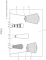
- Fig. 2 shows an example of a camera-captured image 30 captured by camera 3.
- the camera-captured images 30 include yarn cones 2 placed on the top plate 15. In the example in Fig. 2 , five yarn cones 2A-2E are included.
- the yarn cone 2 has a conical core 21 with a yarn 20 wound around it.
- the yarn cones can be placed at any position on the top surface of the top plate 15. Therefore, the number of yarn cones 2 included in the camera-captured image 30 is not fixed but is arbitrary.
- the camera-captured image 30 may include not only the yarn cones 2 on the top plate 15 but also yarn cones 2 that are positioned on creel stands or the like; they are provided in the vicinity of the flat knitting machine 1.
- the imaged statuses of the yarn cones 2 (e.g., external shape and external size), included in the camera-captured images 30, depends on the outer diameter of the core 21, the thickness and the number of turns of yarn 20, and also the status of the use of yarn 20. Furthermore, the imaged statuses of yarn cones 2 also vary according to the relative positions of yarn cones 2 and cameras 3. Furthermore, in camera-captured images 30, a portion of yarn cone 2 at the back may be hidden by another yarn cone 2 at the front.
- the camera-captured images 30 include yarns 20 that are unrolled from yarn cones 2 and connected to the tensioning devices 16.
- the camera-captured image 30 may include objects other than the yarn cones 2, such as the tensioning devices 16.
- the yarn cone 2A is in an unused status in which the yarn cone 2A was installed and not used.
- the outer diameter of the yarn cones decreases and the amounts of yarns remaining also decreases.
- part of the core 21 is exposed through a clearance in the yarn 20.
- the yarn cone eventually becomes “without yarn” as the yarn cone 2E is and the entire core 21 is exposed.
- Cones 2A-2D are in "with yarn” status, and the remaining amounts of yarns are, for example, "100% remaining,” “70% remaining,” “40% remaining,” and "10% remaining.”
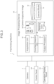
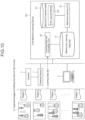
- Fig. 3 is a schematic block diagram of the flat knitting machine 1 provided with the image processing device 4A according to the first embodiment.
- the flat knitting machine 1 includes, as the electrical components: one or plural cameras 3; an image processing device 4A; a control panel 100 including a micro-controller, etc.; and an operation display panel 101 equipped with a touch panel, switches, etc.
- the control panel 100 is connected to actuators such as motors and sensors (both not shown) and controls various parts of the flat knitting machine 1 such that it controls the knitting operation by the flat knitting machine 1.
- the operation display panel 101 accepts the instructions by the operator and outputs various information in the display or as sounds.
- Image processing device 4A comprises a general-purpose or dedicated computer or the like, and comprises: for example, a processor such as a CPU or a GPU; a memory such as ROM or RAM; a communication device for communicating with outer networks or other devices via a wire or wirelessly; and a bus for connecting these parts.
- the image processing device 4A may be incorporated into the control panel 100 as a part of the control panel 100 and may or may not be a stand-alone device.
- the image processing device 4A may consist of a program to cause a processor to perform the operations described below, or a non-transitory computer-readable medium containing one or more instructions for causing the operations to be performed.
- the image processing device 4A further comprises, as shown in Fig. 3 : an acquisition unit 40; and a yarn cone status detection unit 41; a memory for learned model 42; and an output processor 43.
- the acquisition unit 40, the yarn cone status detection unit 41, and the output processor 43 comprise the above processing means, and the memory for learned model 42 comprises the above memory.
- the acquisition unit 40 is connected to the one or plural cameras 3 and functions as an interface for acquiring the image captured by the cameras 3.
- the acquisition unit 40 acquires the camera-captured image 30, including yarn cones 2, on or around the flat knitting machine 1 (positioned on the top plate 15, in this embodiment).
- the connection method and communication method for the connection of the image processing device 4A to the cameras 3 via the acquisition unit 40 is optional.
- the yarn cone status detection unit 41 performs image processing to the camera-captured image 30 acquired by the acquisition unit 40 and detects the statuses of cones 2 included in the camera-captured image 30.
- the statuses of cones 2 include, for example, the amounts of yarns remaining in cones 2, the position, external shape, and external sizes of cones 2, the type (color and thickness) of yarn 20, and the connections between cones 2 and tensioning devices 16.
- the yarn cone status detection unit 41 may detect one or more regarding the statuses of cones 2.
- the yarn cone status detection unit 41 detects the amounts of yarns remaining in cones 2 as the statuses of the yarn cones 2, in this embodiment.
- the yarn cone status detection unit 41 inputs the camera-captured image 30 to the learned model 5A as the input data as image processing for the camera-captured image 30.
- the learned model 5A outputs the inference result (remaining amounts of yarns in cones 2) . The relevant processes will be described.
- the learned model 5A is generated by machine-learning using the machine-learning device 6A and the machine-learning method.
- the learned model 5A performs machine-learning of the correlation between the camera-captured image 30 containing one or plural cones and the remaining amounts of yarns of the cones 2 in the camera-captured image 30.
- the yarn cone status detection unit 41 performs inference using the learned model 5A and applies predetermined image adjustments (e.g., image format, image size, image filter, image mask, etc.) to the camera-captured image 30 as the input data acquired by the acquisition unit 40 as the pre-processing for inference.
- predetermined image adjustments e.g., image format, image size, image filter, image mask, etc.
- the yarn cone status detection unit 41 applies, for example, a predetermined arithmetic or logical formula to the output data (inference result) outputted by the learned model 5A to determine the amounts of yarns remaining in the cones 2.
- the inference results by yarn cone status detection unit 41 may be stored in a memory not shown or may be used for online machine-learning or re-learning, for example, to improve the inference accuracy of the learned model 5A.
- the output processor 43 outputs the detection results detected by the yarn cone status detection unit 41, i.e., the statuses of the yarn cones 2.
- the detection results may be reported to the operator by display or sound via the operation display panel 101. It can be sent and stored in the memory of the control panel 100 as the operation history of the flat knitting machine 1. It may be transmitted to a higher-level production control system of the flat knitting machine 1. In doing so, the output processor 43 may acquire the necessary data (e.g., knitting data, etc.) from the flat knitting machine 1.
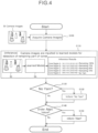
- Fig. 4 is a flowchart showing the image processing method by the image processing device 4A in accordance with the first embodiment.
- the series of image processing processes shown in Fig. 4 are repeatedly executed by the image processing device 4A at predetermined timings.
- the predetermined timing may be, for example, at every predetermined time interval or every production number, or it may be when a predetermined event occurs (e.g., when an operator operates, sets up, or stops the machine).
- the image processing process is performed while the flat knitting machine 1 is knitting.
- the acquisition unit 40 acquires camera-captured image 30 of the yarn cones 2 on the top plate 15 by the cameras 3 (step S100) .
- the yarn cone status detection unit 41 refers to the learned model 5A stored in the memory for learned model 42 and performs inference using this learned model 5A (step S110).
- the learned model 5A to be used for inference is identified in advance based on a predetermined program or worker operation.
- the yarn cone status detection unit 41 pre-processes the camera-captured image 30 acquired by the acquisition unit 40 and inputs it to the learned model 5A. Post-processing is applied to the output data from the learned model 5A by the yarn cone status detection unit 41. In this way, the remaining amounts of yarns of the cones 2 in the camera-captured image 30 are detected as a result of the inference by the learned model 5A.
- step S110 shown in Fig. 4 five cones in five cone regions A-E (lower left and upper right coordinates are indicated) are detected from the camera-captured image 30.
- the remaining amounts of yarns in the five cones 2 are then detected in a multi-level manner. Specifically, the amounts of yarns remaining in the four cone regions A - D are "100% remaining,” “70% remaining,” “40% remaining,” and “10% remaining,” while the amount of yarn remaining in cone region E is "no yarn.”
- step S 110 the yarn cone status detection unit 41 infers the amounts of yarns remaining. Based on this result, the output processor 43 determines whether the remaining amounts of yarns in cones 2 are "no yarn” or not (step S120) . If the output processor 43 makes a positive judgment in step S120 ("Yes" in step S120), it informs the operator that the result of the inference is "no yarn", for example, on the operation display panel 101 (step S130). In other words, the operator is informed that the flat knitting machine 1 shall stop. In Fig. 4 , the cone 2 in the cone region E is reported as "no yarn". At that time, the output processor 43 may notify the control panel 100 that the detection result is "no yarn” and stop the flat knitting machine 1.
- step S140 determines whether the amount of yarn remaining in any cone 2 is less than the alert level that indicates the yarn shall become soon empty (e.g., 10% or less). If the output processor 43 determines positively in step S140 ("Yes” in step S140), it informs the operator that the result of the inference is a "no yarn alert", namely, the yarn shall soon become empty and that the flat knitting machine 1 shall soon stop (step S150). At that time, the output processor 43 may notify the "no yarn alert" on the control panel 100.
- step S140 If the detection result of the amounts of yarns remaining for all cones 2 are not less than the alert level and the output processor 43 judges negatively in step S140 ("NO" in step S140), the image processing process ends without notifying the operator.
- the output processor 43 may output that the detection result is not "no yarn” and "no yarn alert”#, i.e., "with yarn”, and notify on the control panel 100, for example.
- the output processor 43 is configured to output "no yarn” and "no yarn alert” as the detection results. However, the output processor 43 may output only one of them. In that case, any of steps S120, S130, S140, and S150 may be omitted. If the tensioning device 16 has a function to detect “no yarn,” the tensioning device 16 may detect “no yarn” and the output processor 43 may output "no yarn alert.” In that case, steps S120 and S130 may be omitted.
- steps S140 and S150 may be omitted.
- the image processing device 4A and the image processing method according to this embodiment can detect the statuses (in this embodiment, the remaining amounts of yarns) of the yarn cones 2 in the camera-captured image 30. Therefore, there is no need to install optical components for respective cones 2.
- the statuses of cones 2 can be detected without restriction by conditions such as the number or positions of cones 2. Therefore, the statuses of cones 2 can be easily detected, with improved workability and versatility.
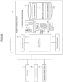
- FIG. 5 is a schematic block diagram of the machine-learning device 6A for the first embodiment.
- the machine-learning device 6A generates a learned model ("learned model 5A") which can detect (estimate) the amounts of yarns remaining in the yarn cones 2 based on a yarn cone image 31 that includes an arbitrary number of yarns cones 2.
- the learned model 5A generated by the machine-learning device 6A is provided to the image processing device 4A and stored in the memory for learned model 42.
- the learned model 5A is thus used for inference by the yarn cone status detection unit 41.
- the image processing device 4A and the machine-learning unit 6A are shown as separate devices. However, the image processing device 4A and the machine-learning unit 6A can be single devices.
- the machine-learning device 6A comprises a general-purpose or dedicated computer or the like.
- the machine-learning device 6A may comprise, for example, a processor such as CPU, GPU, etc.; a memory unit comprising ROM, RAM, etc.; and a communication device for communicating with a network or other devices by wired or wireless means; and a bus connecting these parts.
- the machine-learning device 6A may be provided as a stand-alone device.
- the machine-learning device may be provided in the form of a program for causing a suitable processor to perform predetermined operations, or a non-transitory storage medium containing instructions for performing these operations.
- the machine-learning device 6A has a learning data set acquisition unit 60, a memory for learning data set 61, a machine-learning unit 62, and a memory for a learned model 63, as shown in Fig. 5 .
- the learning data set acquisition unit 60 and the machine-learning unit 62 consists of the processor.
- the memory for learning data set 61 and the memory for learned model 63 consist of the above memory.
- the data set acquisition unit 60 comprises an interface unit, for example, to acquire a plurality of data to form a learning data set (for training) from various devices connected via a communication device.
- the various devices connected to the learning data set acquisition unit 60 are, for example, an external device 7 or a terminal device 8 used by a worker.
- the machine-learning device 6A, the external device 7, and the terminal device 8 are shown as separate devices. However, these devices may be combined as appropriate.
- the external device 7 and the terminal device 8 may be a single device.
- the entire machine-learning device 6A, external device 7, and terminal device 8 may also be a single device.
- the learning data set acquisition unit 60 acquires the yarn cone image 31 as the input data, for example, from the external device 7.
- the learning data set acquisition unit 60 acquires the remaining amounts of yarns of the yarn cones 2 in the yarn cone image 31 as the output data, for example, from the terminal device 8. By mapping these input and output data, a single learning data set is formed.
- the yarn cone image 31 including an arbitrary number of cones is an image containing the arbitrary number of cones 2, as shown in Fig. 2 .
- the yarn cone image 31 may be an image of the yarn cones 2 on or around the flat knitting machine 1 (in this embodiment, on the top plate 15) taken by the camera 3. It may also be, for example, an image of the yarn cones 2 placed on a simulated table that simulates the top plate 15 by a camera for data preparation.
- the amounts of yarns remaining in cones 2 are the information indicating the amounts of yarns 20 remaining wound around the core 21 of cones 2.
- the amounts of yarns remaining in cones 2 comprises information indicating "no yarn” or "yarn available”.
- the amount of yarn remaining is classified into two values, for example, "0" for "no yarn” and "1" for "with yarn.
- the value of the remaining amount of yarn corresponds to the value that the operator, using the terminal device 8, has assigned to the input data.
- the amounts of yarns remaining in cones 2 can be indicated in several steps. In this case, the amount of yarn remaining has many values. For example, when expressing the amount of yarn remaining in eleven steps, the value "0" indicates that there is “no yarn”, “10% remaining", “20% remaining”, ..., “100% remaining", “0.1 “, "0.2”, ..., "1".
- the memory for learning data set 61 for learning is a database and stores the learning data set obtained by the data set acquisition unit 60.
- the structure of the database forming the memory for learning data set 61 can be modified as needed.
- the memory for learning data set 61 and the memory for learned model 63 are shown as separate storage units. However, they can be a single storage unit (database) .
- the machine-learning unit 62 performs machine-learning using a plurality of data sets for learning stored in the memory 61. This generates a learned model ("learned model 5A") so that the correlation between the input data and the output data in the plurality of data sets for learning can be inferred.
- a convolutional neural network CNN (Convolutional Neural Network) which will be described in detail is employed as the specific learning method for machine-learning.
- the memory for learned model 63 is a database for storing the learned model 5A generated by the machine-learning unit 62.
- the learned model 5A stored in the memory for learned model 63 are applied to the real system (image processing device 4A) via communication lines including the Internet or storage media upon request.
- Fig. 6 shows a CNN-based inference model 50A used in the machine-learning device 6A of the first embodiment.
- the inference model 50A has an input layer 51, an intermediate layer 52, and an output layer 53.
- the inference model 50A detects objects in the image (object detection) and detects the status of the detected objects (status detection). When an image contains multiple objects, object detection and status detection are performed for each object.
- the input layer 51 has a number of neurons corresponding to pixels in the image as the input data, and the pixel value of each pixel is inputted to each neuron.
- the intermediate layer 52 comprises convolution layers 520, pooling layers 521 and full connection layer 522.
- the convolution layer 520 and the pooling layer 521 are, for example, provided in alternating layers.
- the convolution layers 520 and the pooling layers 521 extract features from the image input via the input layer 51.
- the full connection layer 522 transforms the features extracted from the image by the convolution layers 520 and the pooling layers 521 using, for example, an activation function into characteristic vector.
- the full connection layer 522 may have multiple layers.
- the output layer 53 outputs output data including the object detection results and the status detection results, as the inference results based on the characteristic vector outputted from the full connection layer 522.
- the object detection result is, for example, information that identifies the region (e.g., rectangle, circle, etc.) that includes the detected object. In the case of a rectangle, the lower left and upper right coordinates may be specified, and the center coordinates, width and height may be specified alternatively.
- the status detection result is, for example, information indicating the status of the detected object, and may be discrete or continuous values.
- the output data may include, for example, a score indicating the certainty of the estimation results.
- the machine-learning unit 62 inputs the learning data set to the inference model 50A and learns the correlation between the yarn cone image 31 and the remaining amounts of yarns of cones 2 in yarn cone image 31. Specifically, the machine-learning unit 62 inputs the yarn cone image 31 which is part of the learning data set, as the input data to the input layer 51 of the inference model 50A. As a pre-processing step in inputting the yarn cone image 31 to the input layer 51, the machine-learning unit 62 may apply image adjustments (e.g., image format, image size, image filter, image mask, etc.) to the yarn cone image 31.
- image adjustments e.g., image format, image size, image filter, image mask, etc.
- the machine-learning unit 62 iteratively adjusts the weights associated with each synapse (back-propagation) so that the value evaluated by the error function is smaller.
- an error function is used that compares the remaining amount of yarn (status detection result) indicated by the output data outputted from the output layer 53 as a result of inference with the remaining amount of yarn (teacher data) in this learning data set.
- the machine-learning unit 62 terminates the learning, with assuming that the learning termination conditions have been met.
- the inference model 50A (all weights associated with each synapse) is then stored in the memory for learned model 63 as the learned model 5A.
- FIG. 7 is a flowchart showing an example of the machine-learning method for the first embodiment.
- the machine-learning method shown below is executed by the machine-learning device 6A, for example.
- a desired number of data sets for learning are prepared as the preliminary preparation for starting the machine-learning.
- the prepared plurality of data sets for learning are stored in the memory 61 (step S200).
- the number of data sets for learning to be prepared is determined by considering the inference accuracy required for the final learned model 5A.
- a learning data set may be obtained, for example, by using a camera for the data preparation to capture the image of the yarn cones 2 placed on a stand that simulates the top plate 15.
- yarn cone image 31 are prepared for the learning data set, in various statuses of the remaining amounts of yarns such as with and without yarn.
- the yarn cone image 31 are prepared including various yarn cones 2 with various positions, various outline shapes, and various outline sizes.
- an inference model 50A before learning is prepared (S210) to begin the learning in the machine-learning unit 62.
- the pre-training inference model 50A prepared here for example, has the structure shown in Fig. 6 , and the weight of each synapse is set to an initial value.
- one learning data set is selected at random, for example (step S220) .
- Input data in the selected learning data set is inputted to the inference model 50A before learning (step S230) .
- the input data is the yarn cone image 31 that contains five cones 2 in the region identified by the five cone regions A to E (lower left and upper right coordinates), and the output data is the information regarding the five cones 2 in the five cone regions A to E with yarn of "100% remaining", “70% remaining %”, “40% remaining”, “10% remaining”, and "no yarn”.
- step S230 the neural network model before training infers the amount of yarn remaining (the result of the status detection) .
- the correct information is not inferred regarding the amounts of yarns remaining in the yarn cones 2. Therefore, machine-learning is performed (step S240) using the teacher data (remaining amount of yarn) in the learning data set obtained in step S220 and the remaining amount of yarn output in step S230.
- the machine-learning here is back-propagation. For example, the process of comparing the remaining amount of yarn in the teacher data with the amount of yarn outputted from the output layer 53 and adjusting the weights assigned to each synapse in the inference model 50A to obtain a preferred inference model 50A.
- the format of the output data in the output layer 53 of the inference model 50A before learning is in the format similar to that of the teacher data.
- step S240 a decision is made as to whether or not to continue machine-learning, e.g., based on the number of remaining untrained data sets for learning (step S250).
- the learning data set is stored in the memory 61. If the learning end condition is not met and machine-learning is to continue ("NO" in step S250), return to step S220. If the learning end condition is satisfied and machine-learning is terminated ("Yes" in step S250), move to step S260. If machine-learning is to continue, steps S220-S240 are performed multiple times on the inference model 50A being trained, using the untrained learning data set. The accuracy of the learned model 5A generated increases with this number of times.
- step S250 When the machine-learning process is completed ("Yes" in step S250), the generated inference model 50A is stored in the memory for learned model 63 as the learned model 5A (step S260). In this way, the series of machine-learning processes are completed.
- the machine-learning process is repeatedly performed on one (pre-trained) inference model 50A to generate one learned model 5A.
- This improves the accuracy and generates a learned model 5A that can be applied to the image processing device 4A.
- the invention is not limited to this acquisition method.
- a plurality of learned model 5A that has been subjected to the machine-learning a predetermined number of times are stored in advance in the learned model memory 63 as one candidate.
- a data set for the determination of validity may be inputted to the multiple learning data set to generate values for the neurons in the output layer.
- the data set for the validation may comprise a data set similar to the learning data set and not having been used for training.
- the machine-learning device 6A and the machine-learning method according to this embodiment can generate a learned model 5A that can accurately detect (estimate) the statuses (remaining amounts of yarns) of the yarn cones 2 from the camera-captured image 30 including one or plural cones 2.
- the machine-learning device 6A generates one learned model 5A.
- the learned model 5A detects the remaining amounts of yarns of cones 2 in the camera-captured image 30.
- the first and second machine-learning devices 6B1 and 6B2 generate the first and second learned models 5B1 and SB2.
- the models SB1 and 5B2 are connected in series such that the first learned model 5B1 is the first stage and the second learned model 5B2 is the second stage.
- the first and second machine-learning devices 6B1 and 6B2 are described as separate devices. However, the first and second machine-learning devices 6B1 and 6B2 may be a single device.
- Fig. 8 is a schematic block diagram of a flat knitting machine 1 equipped with an image processing device 4B according to the second embodiment.
- a first learned model 5B1 and a second learned model 5B2 are stored in the memory for learned model 42 of the image processing device 4B.
- the first learned model 5B1 is generated by the first machine-learning device 6B1 and the machine-learning method.
- the first learned model 5B1 has machine-learned to correlate a cone image 31 containing an arbitrary number of cones 2 with regions in the yarn cone image 31 that contains only one yarn cone 2.
- the second learned model 5B2 is generated by the second machine-learning device 6B2 and the machine-learning method.
- the second learned model 5B2 learns correlation between a single cone image 33 containing one yarn cone 2 and the remaining amount of yarn of the yarn cone 2 in the single cone image 33.
- Fig. 9 is a flowchart, showing the image processing method by the image processing device 4B for the second embodiment.
- the acquisition unit 40 acquires a camera-captured image 30 in which the yarn cones 2 on the top plate 15 are captured by the camera 3 (step S100) .
- the yarn cone status detection unit 41 performs inference using the first learned model 5B1 stored in the memory for learned model 42 (step S111). Specifically, the yarn cone status detection unit 41 inputs the camera-captured image 30 acquired by the acquisition unit 40 into the first learned model 5B1.
- the first learned model 5B1 identifies one or more regions, each containing one yarn cone 2 in the camera-captured image 30.
- five cones 2 are detected in the camera-captured image 30; cone regions A-E containing the five cones 2 are identified with two coordinates, the lower left coordinate and the upper right coordinate.
- the yarn cone status detection unit 41 performs inference (step S112) using the second learned model 5B2 stored in the memory for learned model 42. Specifically, the yarn cone status detection unit 41 inputs to the second learned model 5B2 a region image 32 that includes one yarn cone 2 of the camera-captured image 30 acquired by the acquisition unit 40. By doing so, the second learned model detects the remaining amount of yarn in the one yarn cone 2 included in the region image 32.
- the inference result of step S112 shown in Fig. 9 estimates the amounts of yarns remaining in the five cones from the five regional image 32 corresponding to the five cone regions A-E (identified by the lower left and upper right coordinates).
- the amounts of yarns remaining in the four cones 2 in cone regions A-D are “100% remaining,” “70% remaining,” “40% remaining,” and “10% remaining”; the amount of yarn remaining in cone region E is "no yarn.”
- the yarn cone status detection unit 41 makes inferences. If the detection result of the amount of yarn remaining for any of cones 2 is "no yarn" ("Yes” in step S120) , the output processor 43 reports “no yarn” (step S130) . If the detection result of the amount of yarn remaining for any of the 2 cones is less than or equal to the alert level ("Yes” in step S140), the output processor 43 reports "no yarn alert” (step S150).
- the image processing device 4B and the image processing method according to the embodiment can detect the statuses of one or more cones 2 in the camera-captured image 30 (the remaining amount of yarn in this embodiment). Therefore, there is no need to install optical components for respective cones 2.
- the statuses of cones 2 can be detected without being restricted by the number or positions of cones 2 placed on or around the flat knitting machine. Thus, the statuses of cones 2 can be easily detected, with improved workability and versatility.
- the first machine-learning device 6B1 detects the statuses of one or more cones 2 positioned on or around the top plate of the flat knitting machine 1 and will be described with reference to Figs. 10 and 11 .
- Fig. 10 is a schematic block diagram of the first machine-learning device 6B1 for the second embodiment.
- Fig. 11 shows an example of a first inference model 50B1 based on a CNN used in the first machine-learning device 6B1 for the second embodiment.
- the first machine-learning device 6B1 generates a learned model (first learned model 5B1) that can identify (estimate) an arbitrary number of regions enclosing one yarn cone 2 respectively in the cone image 31, based on the cone image 31 that includes one or more yarn cones 2.
- the learning data set acquisition unit 60 obtains the yarn cone image 31 as the input data, for example, from an external device 7.
- the regions containing one yarn cone 2 respectively in the yarn cone image 31 are acquired as the output data, e.g., from the terminal device 8.
- a learning data set is formed and stored in the memory 61.
- the input data is the cone image 31 which contains five cones 2 in five cone regions A-E (identified by the lower left and upper right coordinates).
- the output data is information identifying cone regions A-E (identified by lower left and upper right coordinates) that contain one yarn cone 2 each.
- the input data which is part of the learning data set may be a single cone image containing one yarn cone 2.
- the machine-learning unit 62 performs the machine-learning using the plurality of data sets for learning stored in the memory 61. This generates the learned model (first learned model 5B1) that infers correlation between input data and output data contained in the plurality of data sets for learning.
- the machine-learning unit 62 performs the machine-learning with learning the yarn cone image 31 which is part of the learning data set, and the yarn cone image 31 is inputted to the input layer 51 of the first inference model 50B1 shown in Fig. 11 .
- the regions outputted from the output layer 53 as the inference result (object detection result) is compared with the regions where the yarn cones are present (the teacher data) that is part of the learning data set.
- the teacher data the regions where the yarn cones are present
- the machine-learning unit 62 stores the first inference model 50B1 as the first learned model 5B1 in the memory for learned model 63.
- the second machine-learning device 6B2 detects the remaining amounts of yarns in one or more cones 2 located on or around the flat knitting machine 1 and will be described with reference to Figs. 12 and 13 .
- Fig. 12 is a schematic block diagram of the second machine-learning device 6B2.
- Fig. 13 shows one example of a second inference model 50B2 based on a CNN used in the second machine-learning device 6B2.
- the second machine-learning device 6B2 generates the learned model (second learned model SB2) based on a single cone image 33 containing one yarn cone 2 and detects (estimates) the remaining amount of yarn of the one yarn cone 2 in the yarn cone image 33.
- the learning data set acquisition unit 60 acquires the single cone image 33, as the input data, for example, from an external device 7. It also acquires output data indicating the amount of yarn remaining in the yarn cone 2 within the single cone image 33, for example, from the terminal device 8. By making these input data and output data correspond with each other, one learning data set is formed. It is stored in the memory for learning data set 61.
- the input data is the single cone image 33 containing only one yarn cone 2
- the output data is the information indicating that the amount of yarn remaining in the cone 2 is "70%.”
- the machine-learning unit 62 performs the machine-learning, using a plurality of learning data set stored in the memory 61.
- the machine-learning generates a learned model (second learned model SB2) that infers correlation between the input data and the output data, both included in the plurality of learning data set.
- the machine-learning unit 62 inputs the single cone image 33 that forms the learning data set into the input layer 51 of the second inference model 50B2 shown in Fig. 13 . Then, the output of the remaining amount of yarn (status detection result) outputted from the output layer 53 as the inference result is compared with the actual remaining amount of yarn (teacher data) in the learning data set. In this way, the machine-learning is conducted.
- the inference result illustrated in Fig. 13 shows that the yarn remaining amount of cone 2 in the single cone image 33 is inferred as "60%.” Since there is an error between the teacher data regarding the remaining amount of yarn in cone 2, the weights of the second inference model 50B2 are adjusted based on the error.
- the machine-learning unit 62 stores the second inference model 50B2 as the second learned model 5B2 in the memory for learned data set 63.
- the first and second machine-learning devices 6B1 and 6B2 and the machine-learning method of the present embodiment generate the first and second learned models 5B1 and SB2 in the same manner as the first machine-learning device 6A and the first machine-learning method.
- the first and second learned models SB1 and SB2 and the machine-learning method can accurately detect (estimate), from the camera-captured image 30 including the arbitrary number of yarn cones 2, the status (in this embodiment, the yarn residue) of the yarn cones 2 in the image 30.
- the first machine-learning device 6B1 generates a first learned model 5B1 such that it identifies regions surrounding one yarn cone 2 respectively in the camera-captured image 30.
- the second machine-learning device 6B2 generates a second learned model 5B2 for detecting the statuses of the respective cones 2. Therefore, there is no need to prepare a large number of images with various combinations of conditions as the necessary learning data set. A learning data set that is suitable for each of the first and second learned models SB1 and 5B is thus simply prepared. This reduces the time and effort required to prepare the learning data set and improves the inference accuracy by the first and second learned models 5B1 and SB2.
- the machine-learning device 6A generates the learned model 5A, and the image processing device 4A detects the remaining amount of yarn in cone 2 in the camera-captured image 30, with inputting the camera-captured image 30 to the learned model 5A.
- the machine-learning device 6C generates a learned model 5C, and the image processing device 4C inputs the camera-captured image 30 to the learned model 5C.
- the learned model 5C detects the connections between the yarn cones 2 and the tensioning devices 16 in the camera-captured image 30. Other points are the same as in the first embodiment. In the following, the characteristics of the third embodiment will be described.
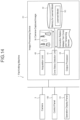
- Fig. 14 is a schematic block diagram showing a flat knitting machine 1 equipped with the image processing device 4C of the third embodiment.
- the learned model 5C is stored in the memory for learned model 42 of the image processing device 4C.
- the learned model 5C has performed the machine-learning, using the machine-learning device 6C and the corresponding machine-learning method, and is capable of correlating the cone image 31 including one or more cones 2 and the connections between the one or more cones 2 and the tensioning devices 16.
- the yarn cone image 31 includes one or more cones 2 and the yarns 20 that are unrolled from the cones 2 and connected to the tensioning devices 16, as shown in Fig. 2 .
- the learned model 5C extracts, from the yarn cone image 31, the position of each cone 2, the direction in which the yarn 20 is unrolled from each cone 2 and extends, and the characteristic quantities that exist in the direction where the yarn 20 extends and learns them, for identifying the connections between the yarn cones 2 and the tensioning devices 16. The aforementioned characteristic quantities are obtained in a range till the yarn reaches the tensioning device 16.
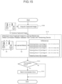
- Fig. 15 is a flowchart showing the image processing method according to the third embodiment of the image processing device 4C. It is assumed that there are n-tensioning devices 16 and that the devices are numbered "1, 2, 3, ..., n" in order from the left to the right, for example.
- the acquisition unit 40 acquires a camera-captured image 30 in which cones 2 on the top plate 15 are captured by the camera 3 (step S100) .
- the yarn cone status detection unit 41 refers to the learned model 5C stored in the memory for learned model 42 and performs the inference process using the learned model 5C (step S113).
- the yarn cone status detection unit 41 inputs the camera-captured image 30 acquired by the acquisition unit 40 to the learned model 5C. Then, the positions of one or more cones 2, the directions in which the yarns 20 are unrolled from cones 2 and extend, and the characteristic quantities that exist in the direction in which the yarns 20 extend are extracted in a range till the tensioning devices 16. These data are used to detect the connections between the yarn cones 2 and the tensioning devices 16 in the camera-captured image 30.
- step S113 shown in Fig. 15 , five cones 2 in five cone regions A-E are detected from the camera-captured image 30.
- the regions are indicated by the lower left and upper right coordinates of the square regions.
- the yarn 20 extending from the cone 2 in the cone region A is connected to the first tensioning device 16
- the yarn 20 extending from the cone 2 in the cone region C is connected to the fourth tensioning device 16
- the yarn 20 extending from the cone 2 in the cone region D is connected to the 10th tensioning device 16
- the yarn 20 extending from the cone 2 in the cone region B is connected to the 17th tensioning device 16.
- the yarn cone 2 in the cone region E has no yarn and is detected as not connected to a tensioning device 16.
- the output processor 43 determines whether the connection between the yarn cones 2 and the tensioning devices 16 detected by the yarn cone status detection unit 41 in step S113 matches the connection in the knitting data of the flat knitting machine 1. If the connections do not match between them ("Yes” in step S121), the operator is informed that a "work error” has occurred (step S131). On the other hand, if the output processor 43 determines that the connections are correct ("NO" in step S121), the image processing process is finished.
- the statuses of one or more cones 2 in the camera-captured image 30 can be detected.
- the connections between the cones 2 and the tensioning devices 16 can be detected. Therefore, there is no need to provide optical components for respective cones 2.
- the statuses of the cones 2 can be detected without restrictions such as the number and positions of the, cones 2 on or around the knitting machine. Therefore, the statuses of the cones 2 can be easily detected, with improved workability and versatility.
- the machine-learning device 6C detects the connection between the yarn cones located on or around the flat knitting machine 1 and the tensioning devices and will be described with reference to Figs. 16 and 17 .
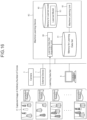
- Fig. 16 is a schematic block diagram of the machine-learning device 6C for the third embodiment.
- Fig. 17 shows an example of a CNN-based inference model 50C used in the machine-learning device 6C according to the third embodiment.
- the machine-learning apparatus 6C uses, as the input data, the cone image 31 including an arbitrary number of cones 2.
- the machine-learning device 6C generates a learned model (learned model 5C) that is capable of detecting (estimation) the correlation between the yarn cones 2 in the image 31 and their connections to the tensioning devices 16.
- the learning data set acquisition unit 60 acquires the yarn cone image 31 as the input data, for example, from the external device 7, and acquires the connections between the yarn cones 2 and the tensioning devices 16 in the yarn cone image 31 as the output data, for example, from the terminal device 8. Then, by making these input data and output data corresponding, the learning data set is formed and stored in the memory 61.
- the input data is the yarn cone image 31.
- Three cones 2 are included in regions defined by the three cone regions A to C (designated by the lower left and upper right coordinates of squares), and the output data is that the yarn cone 2 in the cone region C is connected to the "2nd” tensioning device 16, the yarn cone 2 in the cone region B is connected to the "4th” tensioning device 16, and the yarn cone 2 in the cone region A is connected to the "15th” tensioning device 16.
- the machine-learning unit 62 learns a plurality of learning data set stored in the memory 61 for machine-learning and generates the learned model (learned model 5C) that infers the correlation between the input data and the output data.
- the yarn cone image or cone image 31 in the learning data set are inputted into the input layer 51 of the inference model 50C shown in Fig. 17 .
- the inferred connection relation (the detection result of the relevant status) is outputted from the output layer 53 as the inference result.
- the output is compared with the correct connection data in the learning data set (the teacher data).
- the machine-learning is performed.
- the yarn cone 2 in the cone region C is connected to the 2nd tensioning device
- the yarn cone 2 in the cone region B is connected to the third tensioning device
- the yarn cone 2 in the cone region A is connected to the fifteenth tensioning device.
- the regions are indicated by the lower left and upper right coordinates of squares.
- the machine-learning unit 62 stores the inference model 50C in the memory for learned model 63 as the learned model 5C.
- the output layer 53 of the inference model 50C makes the n-tensioning devices 16 correspond to the yarn cone regions by assigning the serial numbers (identification information) of the tensioning devices 16 to the yarn cone regions.
- the output layer 53 may assign the regions of cone 2 with the serial numbers of tensioning devices 16 connected to cones 2. In such cases, the format of the output data in the learning data set is changed according to the data format of the output layer 53.
- the learned model 5C is generated such it is capable of accurately detecting (estimating) the statuses of the arbitrary number of cones 2 included in a camera-captured image 30, in particular in this embodiment, the connection between the yarn cones 2 and the tensioning devices 16.
- the present invention can be carried out using the inference devices 5A, 5B1, 5B2, and 5C, instead of using the image processing devices 4A-4C.
- the inference devices 5A, 5B1, SB2, and 5C include a memory and at least one processor, and the processor executes the series of processes.
- the series of processes include the process where a camera-captured image 30 including one or plural cones is captured, and the process where, upon input of the camera-captured image 30, the statuses of the yarn cones 2 in the camera-captured image 30 is inferred.
- the remaining yarn amounts in the yarn cones, the connections between the yarn cones and the tensioning devices, and the positions where the yarn cones are located, etc. are inferred.
- the inference devices 5A, 5B1, SB2, and 5C described above can be more easily implemented to various devices than the image processing devices 4A-4C.
- the learned models 5A, 5B1, 5B2, and 5C which have been machine-learned by the machine-learning device 6A, 6B1, 6B2, 6A and the machine-learning method, are usable, and the inference method used by the yarn cone status detection unit 41 in the image processing devices 4A-4C is usable.
- the image processing apparatuses 4A-4C are described as implemented in the flat knitting machines 1A-1C.
- the image processing devices 4A-4C may be implemented in any type of knitting machine, such as a circular knitting machine and a warp knitting machine.
- the image processing devices 4A-4C may, for example, be installed on the knitting machines at the factory where the machine is manufactured, or may be fitted to the knitting machine after shipment from the factory. Further, the functions of the image processing devices 4A-4C may be implemented to the control panels 100 of the knitting machines after shipment from the factory.
- the image processing devices 4A-4C are described as performing the inference using the learning data set as the image processing for the camera-captured image 30.
- the image processing devices 4A-4C may perform pattern recognitions, such as pattern matching, using recognition parameters indicating the features of cone 2 in the camera-captured image 30.
- the above embodiments use the inference models 50A, 50B1, 50B2, and 50C based on CNN, as the learning method for machine-learning.
- other learning methods can be used.
- neural networks ensemble learning (random forest, boosting, etc.), R-CNN (Region-based Convolutional Neural Network), a type of CNN, Fast-R-CNN, Faster-R-CNN, YOLO (You Only Look Once), SSD (Single Shot multi-box Detector) may be used.
- the data format of the input data for the input layer 51 and the output data from the output layer 53 may be changed as appropriate.
Landscapes
- Engineering & Computer Science (AREA)
- Theoretical Computer Science (AREA)
- Textile Engineering (AREA)
- Computer Vision & Pattern Recognition (AREA)
- Physics & Mathematics (AREA)
- General Physics & Mathematics (AREA)
- Software Systems (AREA)
- Evolutionary Computation (AREA)
- Data Mining & Analysis (AREA)
- Medical Informatics (AREA)
- Artificial Intelligence (AREA)
- Computing Systems (AREA)
- General Engineering & Computer Science (AREA)
- Mathematical Physics (AREA)
- Quality & Reliability (AREA)
- Knitting Machines (AREA)
- Image Analysis (AREA)
Abstract
Description
- The present invention relates to an image processing device, a machine-learning device, and an inference device.
- On knitting machines, plural yarn cones which are wound by yarns are arranged on the knitting machines or at the periphery of them. For knitting knitted fabrics (for example, knitted products), various yarn cones are used. The operators of knitting machines exchange yarn cones having yarns which are different in colors and thicknesses according to the knitted fabrics to be knitted. When yarn cones become empty, the knitting machines have to stop, and therefore, the operators have to monitor the residual amounts of yarns of yarn cones manually. Yarns fed from yarn cones are connected to and pass through plural tensioning devices which are arranged on the upper part of knitting machines and then fed to needles with proper tension. The operators of knitting machines have to connect correctly respective yarns fed from respective yarn cones to predetermined tensioning devices. However, the connection between the yarn cones and the tensioning devices via the yarns is sometimes wrong.
- Various devices have been developed to detect the residual amounts of yarns of yarn cones. For example,
Patent Document 1 proposes to irradiate light towards the sides of yarn cones and receive the reflected light thereon to detect the residual amounts of yarns.Patent Document 2 proposes to irradiate light to the bottoms of yarn cones in order to receive light transmitting through the sides of them by a photo-receiving sensor for detecting the residual amounts of yarns when the outer diameters of the yarn cones become smaller. -
- Patent Document 1:
JP H08-277069A - Patent Document 2:
JP 2871318B - The detection devices of residual yarn amounts proposed by
Patent Documents Patent Documents - The object of the invention is to provide an image processing device, a machine-learning device, and an inference device that can detect simply the status an arbitrary number of yarn cones, arranged on the upper part of knitting machine or at the periphery of it, regarding the residual amounts of yarns, the connections to the tensioning devices, and their positions, and have high workability and high versatility.
- The image processing device (4A, 4B, 4C) according to the first aspect of the present invention for achieving the above object comprises:
- an acquisition unit (40) for acquiring a captured image including an arbitrary number of yarn cones, arranged on a knitting machine or at the periphery of the knitting machine; and
- a yarn cone status detection unit (41) for detecting the statuses of the arbitrary number of yarn cones included in the image by applying image processing to the captured image acquired by the acquisition unit (40).
- The machine-learning device (6A) according to the second aspect of the present invention for achieving the above object is used for detecting the residual amounts of yarns of an arbitrary number of yarn cones, arranged on a knitting machine or at the periphery of the knitting machine.
- The machine-learning device (6A) comprises:
- a memory (61) for learning data set for storing a plurality of learning data set each of which comprises input data comprising a captured image including the arbitrary number of yarn cones and output data mapped to the input data and comprising data of residual amounts of yarns of the arbitrary number of yarn cones in the captured image;
- a machine-learning unit machine-learning a model for inferring the correlation between the input data and the output data; and
- a memory for the learned model which has been machine-learned by the machine-learning unit.
- The inference device (5A) according to the third aspect of the present invention for achieving the above object is used for detecting the residual amounts of yarns of an arbitrary number of yarn cones, arranged on a knitting machine or at the periphery of the knitting machine.
- The inference device (5A) comprises a memory and at least a processor, and
- said at least a processor is configured to execute an input process for a captured image including the arbitrary number of yarn cones and
- an inference process inferring the residual amounts of yarns of the arbitrary number of yarn cones in the captured image.
- The machine-learning device (6B1) according to the fourth aspect of the present invention for achieving the above object is used for detecting the statuses of yarn cones, arranged on a knitting machine or at the periphery of the knitting machine.
- The machine-learning device (6B1) comprises: a memory for learning data set (61) storing a plurality of learning data set each of which comprises input data comprising a captured image including an arbitrary number of yarn cones and output data corresponding to said input data and comprising regional information identifying the arbitrary number of regions enclosing one yarn cone respectively in the captured image;
- a machine-learning unit (62) machine-learning a model for inferring the correlation between said input data and said output data according to the input of said plural set of learning data set; and
- a memory for learned model (63) storing the learned model after the machine-learning by said machine-learning unit (62).
- The inference device (SB1) according to the fifth aspect of the present invention for achieving the above object is used for detecting the statuses of yarn cones, arranged on a knitting machine or at the periphery of the knitting machine.
- The inference device (5B1) comprises a memory and at least a processor, and
- said at least a processor is configured to execute an input process for a captured image including an arbitrary number of yarn cones and
- an inference process inferring the regional information identifying the arbitrary number of regions enclosing one yarn cone respectively in the captured image.
- The machine-learning device (6B2) according to the sixth aspect of the present invention for achieving the above object is used for detecting the residual amounts of yarns of an arbitrary number of yarn cones, arranged on a knitting machine or at the periphery of the knitting machine.
- The machine-learning device (6B2) comprises: a memory for learning data set (61) storing a plurality of learning data set each of which comprises input data comprising a captured image including one yarn cone and output data corresponding to said input data and comprising the residual amount of yarn of the yarn cone in the captured image;
- a machine-learning unit (62) machine-learning a model for inferring the correlation between said input data and said output data according to the input of said plural set of learning data set; and
- a memory for learned model (63) storing the learned model after the machine-learning by said machine-learning unit (62).
- The inference device (5B2) according to the seventh aspect of the present invention for achieving the above object is used for detecting the residual amounts of yarns of an arbitrary number of yarn cones, arranged on a knitting machine or at the periphery of the knitting machine.
- The inference device (5B2) comprises a memory and at least a processor, and
- said at least a processor is configured to execute an input process for a captured image including one yarn cone and
- an inference process inferring the residual amount of yarn of the yarn cone in the captured image.
- The machine-learning device (6C) according to the eighth aspect of the present invention for achieving the above object is used for detecting the connection relation between yarn cones, arranged on a knitting machine or at the periphery of the knitting machine, and plural tensioning devices.
- The machine-learning device (6C) comprises: a memory for learning data set (61) storing a plurality of learning data set each of which comprises input data comprising a captured image including an arbitrary number of yarn cones and output data corresponding to said input data and comprising the connection relation between said arbitrary number of yarn cones, and the plural tensioning devices in the captured image;
- a machine-learning unit (62) machine-learning a model for inferring the correlation between said input data and said output data according to the input of said plural set of learning data set; and
- a memory for learned model (63) storing the learned model after the machine-learning by said machine-learning unit (62).
- The inference device (5C) according to the ninth aspect of the present invention for achieving the above object is used for detecting the connection relation between yarn cones, arranged on a knitting machine or at the periphery of the knitting machine, and plural tensioning devices.
- The inference device (5C) comprises a memory and at least a processor, and
- said processor is configured to execute an input process for a captured image including an arbitrary number of cones and
- an inferring process for inferring the connection relation between said arbitrary number of yarn cones and the plural tensioning devices in the captured image.
- According to the image processing device (4A to 4C) and the inference device (5A, 5B1, 5B2, and 5C) of the present invention, the statuses of an arbitrary number of yarn cones in the captured image, for example, the residual amounts of yarns of the yarn cones, the connection relation between the yarn cones and the tensioning devices, the positions of yarn cones, is detectable. Therefore, optical elements for respective yarn cones are not needed. The statuses of yarn cones are detectable without restrictions due to the number and the positions of yarn cones, arranged on the knitting machine or at the periphery of it. Thus, the statuses of yarn cones are simply detectable, and therefore, the workability and versatility are improved.
- In addition, according to the machine-learning device (6A, 6B1, 6B2, and 6C) of the present invention, the machine-learned models (5A, 5B1, 5B2, and 5C) are generated such that they can accurately detect (infer) the statuses of the arbitrary number of yarn cones in the captured image (for example, the residual amounts of yarns of yarn cones, the connection between the yarn cones and the tensioning devices, the arranged positions of yarn cones).
-
- [
Fig. 1 ] A perspective view showing an example of aflat knitting machine 1 according to the first embodiment. - [
Fig. 2 ] A view showing a camera-capturedimage 30 captured bycamera 3. - [
Fig. 3 ] A schematic block diagram showing theflat knitting machine 1 equipped with theimage processing device 4A according to the first embodiment. - [
Fig. 4 ] A flowchart showing an example of the image processing method by theimage processing device 4A according to the first embodiment. - [
Fig. 5 ] A schematic block diagram showing an example of the machine-learningdevice 6A according to the first embodiment. - [
Fig. 6 ] A view indicating an example of aninference model 50A based on a CNN which is used in the machine-learningdevice 6A according to the first embodiment. - [
Fig. 7 ] A flowchart showing an example of the machine-learning method according to the first embodiment. - [
Fig. 8 ] A schematic block diagram showing an example of aflat knitting machine 1 equipped with animage processing device 4B according to the second embodiment. - [
Fig. 9 ] A flowchart showing an example of the image processing method by theimage processing device 4B according to the second embodiment. - [
Fig. 10 ] A schematic block diagram showing an example of the first machine-learning device 6B1 according to the second embodiment. - [
Fig. 11 ] A diagram showing an example of a first inference model 50B1 based on a CNN used in the first machine-learning device 6B1 according to the second embodiment. - [
Fig. 12 ] A schematic block diagram showing an example of a second machine-learning device 6B2 according to the second embodiment. - [
Fig. 13 ] A view indicating an example of a second inference model 50B2 based on a CNN which is used in the second machine-learning device 6B2 according to the second embodiment. - [
Fig. 14 ] A schematic block diagram of an example of aflat knitting machine 1 equipped with an image processing device 4C according to the third embodiment. - [
Fig. 15 ] A flowchart showing an example of an image processing method by the image processing device 4C according to the third embodiment. - [
Fig. 16 ] A schematic block diagram showing an example of a machine-learning device 6C according to the third embodiment. - [
Fig. 17 ] A view indicating an example of an inference model 50C based on a CNN used in the machine-learning device 6C according to the third embodiment. - Embodiments for carrying out the present invention will be described below with reference to the drawings. The following will schematically describe those necessary for achieving the objects of the invention. The description will sometimes be limited to the above, and other portions can be carried out with reference to relevant conventional arts.
-
Fig. 1 is a perspective view of aflat knitting machine 1 according to the first embodiment. - The
flat knitting machine 1 comprises: alower frame 11A that is installed on a floor; a pair ofneedle beds 13 arranged on thelower frame 11A which support a plurality ofneedles 12 in an advanceable and retractable manner and face each other in a front to back relation; a carriage 14 that moves along theneedle beds 13 and makes theneedles 12 advanced, and retracted; and atop plate 15 located over both of theneedle beds 13 and the carriage 14 and supporting one ormore yarn cones 2 on its upper surface. Theflat knitting machine 1 may be provided with a creel stand around it that supports any number ofyarn cones 2. - The
flat knitting machine 1supplies yarns 20 from theyarn cones 2 on thetop plate 15 to theneedles 12. Theflat knitting machine 1 is further provided with a plurality oftensioning devices 16 attached to theupper frame 11B and positioned over thetop plate 15; and aside tensioning devices 17, located, for example, on both sides of thelower frame 11A; and a plurality ofyarn feeders 18 which is selectively caught and moved by the carriage 14. Theyarns 20 from theyarn cones 2 are fed to theneedle 12 via thetensioning devices 16, theside tensioning devices 17, and theyarn feeders 18. - The
flat knitting machine 1 is further equipped with a system for detecting the statuses of theyarn cones 2 on the top plate 15: twocameras 3 are mounted on both left and right sides of theupper frame 11B; and animage processing device 4A is accommodated in thelower frame 11A. - The
cameras 3 are provided with image sensors such as CMOS sensors and CCD sensors and capture one or plural images of thetop plate 15 including the yarn cones from the above. Thecameras 3 are adjusted such that theyarn cones 2 on thetop plate 15 are within the camera-captured image. Thecameras 3 may be equipped with functions for pan, tilt, and zoom, and the number ofcameras 3 is not limited to two, but may be one, three or more. The mounting positions of thecameras 3 can be modified; for example, they may be attached to the ceiling over theflat knitting machine 1. -
Fig. 2 shows an example of a camera-capturedimage 30 captured bycamera 3. - The camera-captured
images 30 includeyarn cones 2 placed on thetop plate 15. In the example inFig. 2 , fiveyarn cones 2A-2E are included. Theyarn cone 2 has aconical core 21 with ayarn 20 wound around it. The yarn cones can be placed at any position on the top surface of thetop plate 15. Therefore, the number ofyarn cones 2 included in the camera-capturedimage 30 is not fixed but is arbitrary. The camera-capturedimage 30 may include not only theyarn cones 2 on thetop plate 15 but alsoyarn cones 2 that are positioned on creel stands or the like; they are provided in the vicinity of theflat knitting machine 1. - The imaged statuses of the yarn cones 2 (e.g., external shape and external size), included in the camera-captured
images 30, depends on the outer diameter of the core 21, the thickness and the number of turns ofyarn 20, and also the status of the use ofyarn 20. Furthermore, the imaged statuses ofyarn cones 2 also vary according to the relative positions ofyarn cones 2 andcameras 3. Furthermore, in camera-capturedimages 30, a portion ofyarn cone 2 at the back may be hidden by anotheryarn cone 2 at the front. In addition toyarn cones 2, the camera-capturedimages 30 includeyarns 20 that are unrolled fromyarn cones 2 and connected to thetensioning devices 16. The camera-capturedimage 30 may include objects other than theyarn cones 2, such as thetensioning devices 16. - In the five
yarn cones 2A-2E included in the camera-capturedimage 30 shown inFig. 2 , theyarn cone 2A is in an unused status in which theyarn cone 2A was installed and not used. As theyarn 20 is gradually used from the unused status, as inyarn cones 2B and 2C, the outer diameter of the yarn cones decreases and the amounts of yarns remaining also decreases. In theyarn cone 2D, part of thecore 21 is exposed through a clearance in theyarn 20. The yarn cone eventually becomes "without yarn" as theyarn cone 2E is and theentire core 21 is exposed.Cones 2A-2D are in "with yarn" status, and the remaining amounts of yarns are, for example, "100% remaining," "70% remaining," "40% remaining," and "10% remaining." -
Fig. 3 is a schematic block diagram of theflat knitting machine 1 provided with theimage processing device 4A according to the first embodiment. - The
flat knitting machine 1 includes, as the electrical components: one orplural cameras 3; animage processing device 4A; acontrol panel 100 including a micro-controller, etc.; and anoperation display panel 101 equipped with a touch panel, switches, etc. Thecontrol panel 100 is connected to actuators such as motors and sensors (both not shown) and controls various parts of theflat knitting machine 1 such that it controls the knitting operation by theflat knitting machine 1. Theoperation display panel 101 accepts the instructions by the operator and outputs various information in the display or as sounds. -
Image processing device 4A comprises a general-purpose or dedicated computer or the like, and comprises: for example, a processor such as a CPU or a GPU; a memory such as ROM or RAM; a communication device for communicating with outer networks or other devices via a wire or wirelessly; and a bus for connecting these parts. Theimage processing device 4A may be incorporated into thecontrol panel 100 as a part of thecontrol panel 100 and may or may not be a stand-alone device. Theimage processing device 4A may consist of a program to cause a processor to perform the operations described below, or a non-transitory computer-readable medium containing one or more instructions for causing the operations to be performed. - The
image processing device 4A further comprises, as shown inFig. 3 : anacquisition unit 40; and a yarn conestatus detection unit 41; a memory for learnedmodel 42; and anoutput processor 43. Theacquisition unit 40, the yarn conestatus detection unit 41, and theoutput processor 43 comprise the above processing means, and the memory for learnedmodel 42 comprises the above memory. - The
acquisition unit 40 is connected to the one orplural cameras 3 and functions as an interface for acquiring the image captured by thecameras 3. Theacquisition unit 40 acquires the camera-capturedimage 30, includingyarn cones 2, on or around the flat knitting machine 1 (positioned on thetop plate 15, in this embodiment). The connection method and communication method for the connection of theimage processing device 4A to thecameras 3 via theacquisition unit 40 is optional. - The yarn cone
status detection unit 41 performs image processing to the camera-capturedimage 30 acquired by theacquisition unit 40 and detects the statuses ofcones 2 included in the camera-capturedimage 30. The statuses ofcones 2 include, for example, the amounts of yarns remaining incones 2, the position, external shape, and external sizes ofcones 2, the type (color and thickness) ofyarn 20, and the connections betweencones 2 andtensioning devices 16. The yarn conestatus detection unit 41 may detect one or more regarding the statuses ofcones 2. - The yarn cone
status detection unit 41 detects the amounts of yarns remaining incones 2 as the statuses of theyarn cones 2, in this embodiment. The yarn conestatus detection unit 41 inputs the camera-capturedimage 30 to the learnedmodel 5A as the input data as image processing for the camera-capturedimage 30. The learnedmodel 5A outputs the inference result (remaining amounts of yarns in cones 2) . The relevant processes will be described. - The learned
model 5A is generated by machine-learning using the machine-learningdevice 6A and the machine-learning method. The learnedmodel 5A performs machine-learning of the correlation between the camera-capturedimage 30 containing one or plural cones and the remaining amounts of yarns of thecones 2 in the camera-capturedimage 30. - The yarn cone
status detection unit 41 performs inference using the learnedmodel 5A and applies predetermined image adjustments (e.g., image format, image size, image filter, image mask, etc.) to the camera-capturedimage 30 as the input data acquired by theacquisition unit 40 as the pre-processing for inference. As a post-processing step of inference, the yarn conestatus detection unit 41 applies, for example, a predetermined arithmetic or logical formula to the output data (inference result) outputted by the learnedmodel 5A to determine the amounts of yarns remaining in thecones 2. The inference results by yarn conestatus detection unit 41 may be stored in a memory not shown or may be used for online machine-learning or re-learning, for example, to improve the inference accuracy of the learnedmodel 5A. - The
output processor 43 outputs the detection results detected by the yarn conestatus detection unit 41, i.e., the statuses of theyarn cones 2. Various means can be employed as specific output means. For example, the detection results may be reported to the operator by display or sound via theoperation display panel 101. It can be sent and stored in the memory of thecontrol panel 100 as the operation history of theflat knitting machine 1. It may be transmitted to a higher-level production control system of theflat knitting machine 1. In doing so, theoutput processor 43 may acquire the necessary data (e.g., knitting data, etc.) from theflat knitting machine 1. - The image processing method by the
image processing device 4A will be described with reference toFig. 4. Fig. 4 is a flowchart showing the image processing method by theimage processing device 4A in accordance with the first embodiment. The series of image processing processes shown inFig. 4 are repeatedly executed by theimage processing device 4A at predetermined timings. The predetermined timing may be, for example, at every predetermined time interval or every production number, or it may be when a predetermined event occurs (e.g., when an operator operates, sets up, or stops the machine). In the following, the image processing process is performed while theflat knitting machine 1 is knitting. - When the
flat knitting machine 1 starts knitting,yarns 20 are accordingly supplied from theyarn cones 2 placed on thetop plate 15, and the knitted fabric is knitted. Next, at a predetermined timing, theacquisition unit 40 acquires camera-capturedimage 30 of theyarn cones 2 on thetop plate 15 by the cameras 3 (step S100) . - Then, the yarn cone
status detection unit 41 refers to the learnedmodel 5A stored in the memory for learnedmodel 42 and performs inference using this learnedmodel 5A (step S110). In this case, it is preferable that the learnedmodel 5A to be used for inference is identified in advance based on a predetermined program or worker operation. - Specifically, the yarn cone
status detection unit 41 pre-processes the camera-capturedimage 30 acquired by theacquisition unit 40 and inputs it to the learnedmodel 5A. Post-processing is applied to the output data from the learnedmodel 5A by the yarn conestatus detection unit 41. In this way, the remaining amounts of yarns of thecones 2 in the camera-capturedimage 30 are detected as a result of the inference by the learnedmodel 5A. In the inference result of step S110 shown inFig. 4 , five cones in five cone regions A-E (lower left and upper right coordinates are indicated) are detected from the camera-capturedimage 30. The remaining amounts of yarns in the fivecones 2 are then detected in a multi-level manner. Specifically, the amounts of yarns remaining in the four cone regions A - D are "100% remaining," "70% remaining," "40% remaining," and "10% remaining," while the amount of yarn remaining in cone region E is "no yarn." - In step S 110, the yarn cone
status detection unit 41 infers the amounts of yarns remaining. Based on this result, theoutput processor 43 determines whether the remaining amounts of yarns incones 2 are "no yarn" or not (step S120) . If theoutput processor 43 makes a positive judgment in step S120 ("Yes" in step S120), it informs the operator that the result of the inference is "no yarn", for example, on the operation display panel 101 (step S130). In other words, the operator is informed that theflat knitting machine 1 shall stop. InFig. 4 , thecone 2 in the cone region E is reported as "no yarn". At that time, theoutput processor 43 may notify thecontrol panel 100 that the detection result is "no yarn" and stop theflat knitting machine 1. - If all
cones 2 are not "no yarn" ("NO" in step S120), theoutput processor 43 determines (step S140) whether the amount of yarn remaining in anycone 2 is less than the alert level that indicates the yarn shall become soon empty (e.g., 10% or less). If theoutput processor 43 determines positively in step S140 ("Yes" in step S140), it informs the operator that the result of the inference is a "no yarn alert", namely, the yarn shall soon become empty and that theflat knitting machine 1 shall soon stop (step S150). At that time, theoutput processor 43 may notify the "no yarn alert" on thecontrol panel 100. - If the detection result of the amounts of yarns remaining for all
cones 2 are not less than the alert level and theoutput processor 43 judges negatively in step S140 ("NO" in step S140), the image processing process ends without notifying the operator. Theoutput processor 43 may output that the detection result is not "no yarn" and "no yarn alert"#, i.e., "with yarn", and notify on thecontrol panel 100, for example. - The
output processor 43 is configured to output "no yarn" and "no yarn alert" as the detection results. However, theoutput processor 43 may output only one of them. In that case, any of steps S120, S130, S140, and S150 may be omitted. If thetensioning device 16 has a function to detect "no yarn," thetensioning device 16 may detect "no yarn" and theoutput processor 43 may output "no yarn alert." In that case, steps S120 and S130 may be omitted. Furthermore, if the remaining amounts of yarns are detected in a binary value, for example, if the detection result of the remaining amounts of yarns in the fourcones 2 in cone regions A-D is "with yarn" and the detection result of the remaining amount of yarn in cone region E is "no yarn," steps S140 and S150 may be omitted. - As described above, the
image processing device 4A and the image processing method according to this embodiment can detect the statuses (in this embodiment, the remaining amounts of yarns) of theyarn cones 2 in the camera-capturedimage 30. Therefore, there is no need to install optical components forrespective cones 2. The statuses ofcones 2 can be detected without restriction by conditions such as the number or positions ofcones 2. Therefore, the statuses ofcones 2 can be easily detected, with improved workability and versatility. - A machine-learning
device 6A for detecting the amounts of yarns remaining in one ormore cones 2 located on the top panel of theflat knitting machine 1 or in the vicinity of the flat knitting machine will be described with reference toFig. 5. Fig. 5 is a schematic block diagram of the machine-learningdevice 6A for the first embodiment. - The machine-learning
device 6A generates a learned model ("learnedmodel 5A") which can detect (estimate) the amounts of yarns remaining in theyarn cones 2 based on ayarn cone image 31 that includes an arbitrary number ofyarns cones 2. The learnedmodel 5A generated by the machine-learningdevice 6A is provided to theimage processing device 4A and stored in the memory for learnedmodel 42. The learnedmodel 5A is thus used for inference by the yarn conestatus detection unit 41. Here, theimage processing device 4A and the machine-learning unit 6A are shown as separate devices. However, theimage processing device 4A and the machine-learning unit 6A can be single devices. - The machine-learning
device 6A comprises a general-purpose or dedicated computer or the like. The machine-learningdevice 6A may comprise, for example, a processor such as CPU, GPU, etc.; a memory unit comprising ROM, RAM, etc.; and a communication device for communicating with a network or other devices by wired or wireless means; and a bus connecting these parts. The machine-learningdevice 6A may be provided as a stand-alone device. The machine-learning device may be provided in the form of a program for causing a suitable processor to perform predetermined operations, or a non-transitory storage medium containing instructions for performing these operations. - The machine-learning
device 6A has a learning dataset acquisition unit 60, a memory for learningdata set 61, a machine-learningunit 62, and a memory for a learnedmodel 63, as shown inFig. 5 . The learning dataset acquisition unit 60 and the machine-learningunit 62 consists of the processor. The memory for learningdata set 61 and the memory for learnedmodel 63 consist of the above memory. - The data
set acquisition unit 60 comprises an interface unit, for example, to acquire a plurality of data to form a learning data set (for training) from various devices connected via a communication device. Here, the various devices connected to the learning dataset acquisition unit 60 are, for example, anexternal device 7 or aterminal device 8 used by a worker. InFig. 5 , the machine-learningdevice 6A, theexternal device 7, and theterminal device 8 are shown as separate devices. However, these devices may be combined as appropriate. For example, theexternal device 7 and theterminal device 8 may be a single device. The entire machine-learningdevice 6A,external device 7, andterminal device 8 may also be a single device. - The learning data
set acquisition unit 60 acquires theyarn cone image 31 as the input data, for example, from theexternal device 7. The learning dataset acquisition unit 60 acquires the remaining amounts of yarns of theyarn cones 2 in theyarn cone image 31 as the output data, for example, from theterminal device 8. By mapping these input and output data, a single learning data set is formed. - The
yarn cone image 31 including an arbitrary number of cones is an image containing the arbitrary number ofcones 2, as shown inFig. 2 . Theyarn cone image 31 may be an image of theyarn cones 2 on or around the flat knitting machine 1 (in this embodiment, on the top plate 15) taken by thecamera 3. It may also be, for example, an image of theyarn cones 2 placed on a simulated table that simulates thetop plate 15 by a camera for data preparation. - The amounts of yarns remaining in
cones 2 are the information indicating the amounts ofyarns 20 remaining wound around thecore 21 ofcones 2. Various data formats can be used for this data. For example, the amounts of yarns remaining incones 2 comprises information indicating "no yarn" or "yarn available". In this case, the amount of yarn remaining is classified into two values, for example, "0" for "no yarn" and "1" for "with yarn. The value of the remaining amount of yarn corresponds to the value that the operator, using theterminal device 8, has assigned to the input data. The amounts of yarns remaining incones 2 can be indicated in several steps. In this case, the amount of yarn remaining has many values. For example, when expressing the amount of yarn remaining in eleven steps, the value "0" indicates that there is "no yarn", "10% remaining", "20% remaining", ..., "100% remaining", "0.1 ", "0.2", ..., "1". - The memory for learning
data set 61 for learning is a database and stores the learning data set obtained by the data setacquisition unit 60. The structure of the database forming the memory for learning data set 61 can be modified as needed. For example, inFig. 5 , the memory for learningdata set 61 and the memory for learnedmodel 63 are shown as separate storage units. However, they can be a single storage unit (database) . - The machine-learning
unit 62 performs machine-learning using a plurality of data sets for learning stored in thememory 61. This generates a learned model ("learnedmodel 5A") so that the correlation between the input data and the output data in the plurality of data sets for learning can be inferred. In the embodiment, a convolutional neural network (CNN (Convolutional Neural Network)) which will be described in detail is employed as the specific learning method for machine-learning. - The memory for learned
model 63 is a database for storing the learnedmodel 5A generated by the machine-learningunit 62. The learnedmodel 5A stored in the memory for learnedmodel 63 are applied to the real system (image processing device 4A) via communication lines including the Internet or storage media upon request. - Next, the learning method in the machine-learning
unit 62 using the multiple acquired data sets for learning will be described with reference toFig. 6. Fig. 6 shows a CNN-basedinference model 50A used in the machine-learningdevice 6A of the first embodiment. - The
inference model 50A has aninput layer 51, anintermediate layer 52, and anoutput layer 53. Theinference model 50A detects objects in the image (object detection) and detects the status of the detected objects (status detection). When an image contains multiple objects, object detection and status detection are performed for each object. - The
input layer 51 has a number of neurons corresponding to pixels in the image as the input data, and the pixel value of each pixel is inputted to each neuron. - The
intermediate layer 52 comprises convolution layers 520, poolinglayers 521 andfull connection layer 522. Theconvolution layer 520 and thepooling layer 521 are, for example, provided in alternating layers. The convolution layers 520 and the pooling layers 521 extract features from the image input via theinput layer 51. Thefull connection layer 522 transforms the features extracted from the image by the convolution layers 520 and the pooling layers 521 using, for example, an activation function into characteristic vector. Thefull connection layer 522 may have multiple layers. - The
output layer 53 outputs output data including the object detection results and the status detection results, as the inference results based on the characteristic vector outputted from thefull connection layer 522. The object detection result is, for example, information that identifies the region (e.g., rectangle, circle, etc.) that includes the detected object. In the case of a rectangle, the lower left and upper right coordinates may be specified, and the center coordinates, width and height may be specified alternatively. The status detection result is, for example, information indicating the status of the detected object, and may be discrete or continuous values. In addition to them, the output data may include, for example, a score indicating the certainty of the estimation results. - Between the layers of the
inference model 50A, there are synapses connecting the neurons in the layers. Synapses in theconvolutional layer 520 and thefull connection layer 522 of theintermediate layer 52 have weights associated with them. - The machine-learning
unit 62 inputs the learning data set to theinference model 50A and learns the correlation between theyarn cone image 31 and the remaining amounts of yarns ofcones 2 inyarn cone image 31. Specifically, the machine-learningunit 62 inputs theyarn cone image 31 which is part of the learning data set, as the input data to theinput layer 51 of theinference model 50A. As a pre-processing step in inputting theyarn cone image 31 to theinput layer 51, the machine-learningunit 62 may apply image adjustments (e.g., image format, image size, image filter, image mask, etc.) to theyarn cone image 31. - The machine-learning
unit 62 iteratively adjusts the weights associated with each synapse (back-propagation) so that the value evaluated by the error function is smaller. To evaluate the error, an error function is used that compares the remaining amount of yarn (status detection result) indicated by the output data outputted from theoutput layer 53 as a result of inference with the remaining amount of yarn (teacher data) in this learning data set. - When the series of steps have been performed a predetermined number of times, or when the evaluated value of the error function is smaller than the allowable value, the machine-learning
unit 62 terminates the learning, with assuming that the learning termination conditions have been met. Theinference model 50A (all weights associated with each synapse) is then stored in the memory for learnedmodel 63 as the learnedmodel 5A. - A machine-learning method corresponding to the machine-learning
device 6A will be described with reference toFig. 7. Fig. 7 is a flowchart showing an example of the machine-learning method for the first embodiment. - The machine-learning method shown below is executed by the machine-learning
device 6A, for example. First, a desired number of data sets for learning are prepared as the preliminary preparation for starting the machine-learning. The prepared plurality of data sets for learning are stored in the memory 61 (step S200). The number of data sets for learning to be prepared is determined by considering the inference accuracy required for the final learnedmodel 5A. - Several methods can be employed to prepare the data sets for learning. For example, during operation of the
flat knitting machine 1, thecameras 3 are used to capture the image of theyarn cones 2 in various statuses. The operator inputs the remaining amounts of yarns in thecones 2 in theyarn cone image 31 using aterminal device 8 or the like, so as to associate them with the capturedcone image 31. By repeating this process, the desired number of data sets for learning are prepared. In addition to this method, a learning data set may be obtained, for example, by using a camera for the data preparation to capture the image of theyarn cones 2 placed on a stand that simulates thetop plate 15. In doing so,yarn cone image 31 are prepared for the learning data set, in various statuses of the remaining amounts of yarns such as with and without yarn. Preferably, theyarn cone image 31 are prepared includingvarious yarn cones 2 with various positions, various outline shapes, and various outline sizes. - Next, an
inference model 50A before learning is prepared (S210) to begin the learning in the machine-learningunit 62. Thepre-training inference model 50A prepared here, for example, has the structure shown inFig. 6 , and the weight of each synapse is set to an initial value. From the plurality of data sets for learning stored in thememory 61, one learning data set is selected at random, for example (step S220) . Input data in the selected learning data set is inputted to theinference model 50A before learning (step S230) . In the learning data set shown inFig. 6 , the input data is theyarn cone image 31 that contains fivecones 2 in the region identified by the five cone regions A to E (lower left and upper right coordinates), and the output data is the information regarding the fivecones 2 in the five cone regions A to E with yarn of "100% remaining", "70% remaining %", "40% remaining", "10% remaining", and "no yarn". - In step S230, the neural network model before training infers the amount of yarn remaining (the result of the status detection) . In most cases, the correct information is not inferred regarding the amounts of yarns remaining in the
yarn cones 2. Therefore, machine-learning is performed (step S240) using the teacher data (remaining amount of yarn) in the learning data set obtained in step S220 and the remaining amount of yarn output in step S230. - The machine-learning here is back-propagation. For example, the process of comparing the remaining amount of yarn in the teacher data with the amount of yarn outputted from the
output layer 53 and adjusting the weights assigned to each synapse in theinference model 50A to obtain apreferred inference model 50A. The format of the output data in theoutput layer 53 of theinference model 50A before learning is in the format similar to that of the teacher data. - In the inference result shown in
Fig. 6 , fivecones 2 in five cone regions A-E (lower left and upper right coordinates) are detected in theyarn cone image 31. The amounts of yarns remaining in the five cone regions A-E are "100% remaining", "60% remaining", "40% remaining", "10% remaining" and "no yarn". The following are the remaining yarn amounts for the five cones in cone region A-E. There is an error with the teacher data for the amounts of yarns remaining incones 2 in cone region B. Based on this error, the weights of theinference model 50A are adjusted. - Once the machine-learning is performed in step S240, a decision is made as to whether or not to continue machine-learning, e.g., based on the number of remaining untrained data sets for learning (step S250). The learning data set is stored in the
memory 61. If the learning end condition is not met and machine-learning is to continue ("NO" in step S250), return to step S220. If the learning end condition is satisfied and machine-learning is terminated ("Yes" in step S250), move to step S260. If machine-learning is to continue, steps S220-S240 are performed multiple times on theinference model 50A being trained, using the untrained learning data set. The accuracy of the learnedmodel 5A generated increases with this number of times. - When the machine-learning process is completed ("Yes" in step S250), the generated
inference model 50A is stored in the memory for learnedmodel 63 as the learnedmodel 5A (step S260). In this way, the series of machine-learning processes are completed. - In the learning method and the machine-learning method of the machine-learning
device 6A, the machine-learning process is repeatedly performed on one (pre-trained)inference model 50A to generate one learnedmodel 5A. This improves the accuracy and generates a learnedmodel 5A that can be applied to theimage processing device 4A. However, the invention is not limited to this acquisition method. For example, a plurality of learnedmodel 5A that has been subjected to the machine-learning a predetermined number of times are stored in advance in the learnedmodel memory 63 as one candidate. For example, a data set for the determination of validity may be inputted to the multiple learning data set to generate values for the neurons in the output layer. Then, the accuracy of the values identified in the output layer are compared and considered, and the best learnedmodel 5A to be applied to theimage processing device 4A may be selected. The data set for the validation may comprise a data set similar to the learning data set and not having been used for training. - As described above, the machine-learning
device 6A and the machine-learning method according to this embodiment can generate a learnedmodel 5A that can accurately detect (estimate) the statuses (remaining amounts of yarns) of theyarn cones 2 from the camera-capturedimage 30 including one orplural cones 2. - In the first embodiment, the machine-learning
device 6A generates one learnedmodel 5A. When theimage processing device 4A inputs the camera-capturedimage 30 to the learnedmodel 5A, the learnedmodel 5A detects the remaining amounts of yarns ofcones 2 in the camera-capturedimage 30. In contrast, in the second embodiment, the first and second machine-learning devices 6B1 and 6B2 generate the first and second learned models 5B1 and SB2. In theimage processing device 4B, the models SB1 and 5B2 are connected in series such that the first learned model 5B1 is the first stage and the second learned model 5B2 is the second stage. When a camera-capturedimage 30 is inputted to the first learned model 5B1, it detects the remaining amounts of yarns ofcones 2 in the camera-capturedimage 30. The other basic structure and operation are the same as in the first embodiment. The characteristic parts of the second embodiment are described. The first and second machine-learning devices 6B1 and 6B2 are described as separate devices. However, the first and second machine-learning devices 6B1 and 6B2 may be a single device. -
Fig. 8 is a schematic block diagram of aflat knitting machine 1 equipped with animage processing device 4B according to the second embodiment. A first learned model 5B1 and a second learned model 5B2 are stored in the memory for learnedmodel 42 of theimage processing device 4B. - The first learned model 5B1 is generated by the first machine-learning device 6B1 and the machine-learning method. The first learned model 5B1 has machine-learned to correlate a
cone image 31 containing an arbitrary number ofcones 2 with regions in theyarn cone image 31 that contains only oneyarn cone 2. - The second learned model 5B2 is generated by the second machine-learning device 6B2 and the machine-learning method. The second learned model 5B2 learns correlation between a
single cone image 33 containing oneyarn cone 2 and the remaining amount of yarn of theyarn cone 2 in thesingle cone image 33. -
Fig. 9 is a flowchart, showing the image processing method by theimage processing device 4B for the second embodiment. - At a predetermined timing, the
acquisition unit 40 acquires a camera-capturedimage 30 in which theyarn cones 2 on thetop plate 15 are captured by the camera 3 (step S100) . - The yarn cone
status detection unit 41 performs inference using the first learned model 5B1 stored in the memory for learned model 42 (step S111). Specifically, the yarn conestatus detection unit 41 inputs the camera-capturedimage 30 acquired by theacquisition unit 40 into the first learned model 5B1. The first learned model 5B1 identifies one or more regions, each containing oneyarn cone 2 in the camera-capturedimage 30. In the inference result of step S111 shown inFig. 9 , fivecones 2 are detected in the camera-capturedimage 30; cone regions A-E containing the fivecones 2 are identified with two coordinates, the lower left coordinate and the upper right coordinate. - The yarn cone
status detection unit 41 performs inference (step S112) using the second learned model 5B2 stored in the memory for learnedmodel 42. Specifically, the yarn conestatus detection unit 41 inputs to the second learned model 5B2 aregion image 32 that includes oneyarn cone 2 of the camera-capturedimage 30 acquired by theacquisition unit 40. By doing so, the second learned model detects the remaining amount of yarn in the oneyarn cone 2 included in theregion image 32. The inference result of step S112 shown inFig. 9 estimates the amounts of yarns remaining in the five cones from the fiveregional image 32 corresponding to the five cone regions A-E (identified by the lower left and upper right coordinates). The amounts of yarns remaining in the fourcones 2 in cone regions A-D (lower left and upper right coordinates) are "100% remaining," "70% remaining," "40% remaining," and "10% remaining"; the amount of yarn remaining in cone region E is "no yarn." - In steps S111 and S112, the yarn cone
status detection unit 41 makes inferences. If the detection result of the amount of yarn remaining for any ofcones 2 is "no yarn" ("Yes" in step S120) , theoutput processor 43 reports "no yarn" (step S130) . If the detection result of the amount of yarn remaining for any of the 2 cones is less than or equal to the alert level ("Yes" in step S140), theoutput processor 43 reports "no yarn alert" (step S150). If the detection result of the amounts of yarns remaining for allcones 2 is neither "no yarn" nor "no yarn alert", i.e., the detection result of the amounts of yarns remaining for allcones 2 is "with yarn" ("NO" in step S120 and "NO" in step S140), the image processing process is completed. - Similar to the
image processing device 4A and the image processing method, theimage processing device 4B and the image processing method according to the embodiment can detect the statuses of one ormore cones 2 in the camera-captured image 30 (the remaining amount of yarn in this embodiment). Therefore, there is no need to install optical components forrespective cones 2. The statuses ofcones 2 can be detected without being restricted by the number or positions ofcones 2 placed on or around the flat knitting machine. Thus, the statuses ofcones 2 can be easily detected, with improved workability and versatility. - The first machine-learning device 6B1 detects the statuses of one or
more cones 2 positioned on or around the top plate of theflat knitting machine 1 and will be described with reference toFigs. 10 and11 .Fig. 10 is a schematic block diagram of the first machine-learning device 6B1 for the second embodiment.Fig. 11 shows an example of a first inference model 50B1 based on a CNN used in the first machine-learning device 6B1 for the second embodiment. - The first machine-learning device 6B1 generates a learned model (first learned model 5B1) that can identify (estimate) an arbitrary number of regions enclosing one
yarn cone 2 respectively in thecone image 31, based on thecone image 31 that includes one ormore yarn cones 2. - The learning data
set acquisition unit 60 obtains theyarn cone image 31 as the input data, for example, from anexternal device 7. The regions containing oneyarn cone 2 respectively in theyarn cone image 31 are acquired as the output data, e.g., from theterminal device 8. By mapping these input and output data, a learning data set is formed and stored in thememory 61. In the learning data set shown inFig. 11 , the input data is thecone image 31 which contains fivecones 2 in five cone regions A-E (identified by the lower left and upper right coordinates). The output data is information identifying cone regions A-E (identified by lower left and upper right coordinates) that contain oneyarn cone 2 each. The input data which is part of the learning data set, may be a single cone image containing oneyarn cone 2. - The machine-learning
unit 62 performs the machine-learning using the plurality of data sets for learning stored in thememory 61. This generates the learned model (first learned model 5B1) that infers correlation between input data and output data contained in the plurality of data sets for learning. - Specifically, the machine-learning
unit 62 performs the machine-learning with learning theyarn cone image 31 which is part of the learning data set, and theyarn cone image 31 is inputted to theinput layer 51 of the first inference model 50B1 shown inFig. 11 . The regions outputted from theoutput layer 53 as the inference result (object detection result) is compared with the regions where the yarn cones are present (the teacher data) that is part of the learning data set. For example, in the inference result shown inFig. 11 , fivecones 2 are detected in five cone regions A-E (lower left and upper right coordinates are specified) from thecone image 31. The cone regions A-E, which contain five cones, are identified by their two points, namely, the lower left and upper right coordinates. If there is an error between the inference results and the teacher data for the cone regions A-E, the weights in the first inference model 50B1 are adjusted based on the error. - When the learning end condition is met and the machine-learning is completed, the machine-learning
unit 62 stores the first inference model 50B1 as the first learned model 5B1 in the memory for learnedmodel 63. - The second machine-learning device 6B2 detects the remaining amounts of yarns in one or
more cones 2 located on or around theflat knitting machine 1 and will be described with reference toFigs. 12 and13 .Fig. 12 is a schematic block diagram of the second machine-learning device 6B2.Fig. 13 shows one example of a second inference model 50B2 based on a CNN used in the second machine-learning device 6B2. - The second machine-learning device 6B2 generates the learned model (second learned model SB2) based on a
single cone image 33 containing oneyarn cone 2 and detects (estimates) the remaining amount of yarn of the oneyarn cone 2 in theyarn cone image 33. - The learning data
set acquisition unit 60 acquires thesingle cone image 33, as the input data, for example, from anexternal device 7. It also acquires output data indicating the amount of yarn remaining in theyarn cone 2 within thesingle cone image 33, for example, from theterminal device 8. By making these input data and output data correspond with each other, one learning data set is formed. It is stored in the memory for learningdata set 61. In the learning data set illustrated inFig. 13 , the input data is thesingle cone image 33 containing only oneyarn cone 2, and the output data is the information indicating that the amount of yarn remaining in thecone 2 is "70%." - The machine-learning
unit 62 performs the machine-learning, using a plurality of learning data set stored in thememory 61. The machine-learning generates a learned model (second learned model SB2) that infers correlation between the input data and the output data, both included in the plurality of learning data set. - Specifically, the machine-learning
unit 62 inputs thesingle cone image 33 that forms the learning data set into theinput layer 51 of the second inference model 50B2 shown inFig. 13 . Then, the output of the remaining amount of yarn (status detection result) outputted from theoutput layer 53 as the inference result is compared with the actual remaining amount of yarn (teacher data) in the learning data set. In this way, the machine-learning is conducted. The inference result illustrated inFig. 13 shows that the yarn remaining amount ofcone 2 in thesingle cone image 33 is inferred as "60%." Since there is an error between the teacher data regarding the remaining amount of yarn incone 2, the weights of the second inference model 50B2 are adjusted based on the error. - When the learning end condition is satisfied, and machine-learning is finished, the machine-learning
unit 62 stores the second inference model 50B2 as the second learned model 5B2 in the memory for learneddata set 63. - The first and second machine-learning devices 6B1 and 6B2 and the machine-learning method of the present embodiment generate the first and second learned models 5B1 and SB2 in the same manner as the first machine-learning
device 6A and the first machine-learning method. The first and second learned models SB1 and SB2 and the machine-learning method can accurately detect (estimate), from the camera-capturedimage 30 including the arbitrary number ofyarn cones 2, the status (in this embodiment, the yarn residue) of theyarn cones 2 in theimage 30. - In particular, the first machine-learning device 6B1 generates a first learned model 5B1 such that it identifies regions surrounding one
yarn cone 2 respectively in the camera-capturedimage 30. The second machine-learning device 6B2 generates a second learned model 5B2 for detecting the statuses of therespective cones 2. Therefore, there is no need to prepare a large number of images with various combinations of conditions as the necessary learning data set. A learning data set that is suitable for each of the first and second learned models SB1 and 5B is thus simply prepared. This reduces the time and effort required to prepare the learning data set and improves the inference accuracy by the first and second learned models 5B1 and SB2. - In the first embodiment, the machine-learning
device 6A generates the learnedmodel 5A, and theimage processing device 4A detects the remaining amount of yarn incone 2 in the camera-capturedimage 30, with inputting the camera-capturedimage 30 to the learnedmodel 5A. In the third embodiment, the machine-learning device 6C generates a learnedmodel 5C, and the image processing device 4C inputs the camera-capturedimage 30 to the learnedmodel 5C. The learnedmodel 5C detects the connections between theyarn cones 2 and thetensioning devices 16 in the camera-capturedimage 30. Other points are the same as in the first embodiment. In the following, the characteristics of the third embodiment will be described. -
Fig. 14 is a schematic block diagram showing aflat knitting machine 1 equipped with the image processing device 4C of the third embodiment. The learnedmodel 5C is stored in the memory for learnedmodel 42 of the image processing device 4C. - The learned
model 5C has performed the machine-learning, using the machine-learning device 6C and the corresponding machine-learning method, and is capable of correlating thecone image 31 including one ormore cones 2 and the connections between the one ormore cones 2 and thetensioning devices 16. Specifically, theyarn cone image 31 includes one ormore cones 2 and theyarns 20 that are unrolled from thecones 2 and connected to thetensioning devices 16, as shown inFig. 2 . The learnedmodel 5C extracts, from theyarn cone image 31, the position of eachcone 2, the direction in which theyarn 20 is unrolled from eachcone 2 and extends, and the characteristic quantities that exist in the direction where theyarn 20 extends and learns them, for identifying the connections between theyarn cones 2 and thetensioning devices 16. The aforementioned characteristic quantities are obtained in a range till the yarn reaches thetensioning device 16. -
Fig. 15 is a flowchart showing the image processing method according to the third embodiment of the image processing device 4C. It is assumed that there are n-tensioningdevices 16 and that the devices are numbered "1, 2, 3, ..., n" in order from the left to the right, for example. - At a predetermined timing, the
acquisition unit 40 acquires a camera-capturedimage 30 in whichcones 2 on thetop plate 15 are captured by the camera 3 (step S100) . - The yarn cone
status detection unit 41 refers to the learnedmodel 5C stored in the memory for learnedmodel 42 and performs the inference process using the learnedmodel 5C (step S113). The yarn conestatus detection unit 41 inputs the camera-capturedimage 30 acquired by theacquisition unit 40 to the learnedmodel 5C. Then, the positions of one ormore cones 2, the directions in which theyarns 20 are unrolled fromcones 2 and extend, and the characteristic quantities that exist in the direction in which theyarns 20 extend are extracted in a range till thetensioning devices 16. These data are used to detect the connections between theyarn cones 2 and thetensioning devices 16 in the camera-capturedimage 30. - In the inference result of step S113, shown in
Fig. 15 , fivecones 2 in five cone regions A-E are detected from the camera-capturedimage 30. The regions are indicated by the lower left and upper right coordinates of the square regions. Theyarn 20 extending from thecone 2 in the cone region A is connected to thefirst tensioning device 16, theyarn 20 extending from thecone 2 in the cone region C is connected to thefourth tensioning device 16, theyarn 20 extending from thecone 2 in the cone region D is connected to the10th tensioning device 16, and theyarn 20 extending from thecone 2 in the cone region B is connected to the17th tensioning device 16. Theyarn cone 2 in the cone region E has no yarn and is detected as not connected to atensioning device 16. - The
output processor 43 determines whether the connection between theyarn cones 2 and thetensioning devices 16 detected by the yarn conestatus detection unit 41 in step S113 matches the connection in the knitting data of theflat knitting machine 1. If the connections do not match between them ("Yes" in step S121), the operator is informed that a "work error" has occurred (step S131). On the other hand, if theoutput processor 43 determines that the connections are correct ("NO" in step S121), the image processing process is finished. - According to the image processing device 4C and the image processing method according to the embodiment, the statuses of one or
more cones 2 in the camera-capturedimage 30 can be detected. In particular, the connections between thecones 2 and thetensioning devices 16 can be detected. Therefore, there is no need to provide optical components forrespective cones 2. The statuses of thecones 2 can be detected without restrictions such as the number and positions of the,cones 2 on or around the knitting machine. Therefore, the statuses of thecones 2 can be easily detected, with improved workability and versatility. - The machine-learning device 6C detects the connection between the yarn cones located on or around the
flat knitting machine 1 and the tensioning devices and will be described with reference toFigs. 16 and17 .Fig. 16 is a schematic block diagram of the machine-learning device 6C for the third embodiment.Fig. 17 shows an example of a CNN-based inference model 50C used in the machine-learning device 6C according to the third embodiment. - The machine-learning apparatus 6C uses, as the input data, the
cone image 31 including an arbitrary number ofcones 2. The machine-learning device 6C generates a learned model (learnedmodel 5C) that is capable of detecting (estimation) the correlation between theyarn cones 2 in theimage 31 and their connections to thetensioning devices 16. - The learning data
set acquisition unit 60 acquires theyarn cone image 31 as the input data, for example, from theexternal device 7, and acquires the connections between theyarn cones 2 and thetensioning devices 16 in theyarn cone image 31 as the output data, for example, from theterminal device 8. Then, by making these input data and output data corresponding, the learning data set is formed and stored in thememory 61. In the learning data set illustrated inFig. 17 , the input data is theyarn cone image 31. Threecones 2 are included in regions defined by the three cone regions A to C (designated by the lower left and upper right coordinates of squares), and the output data is that theyarn cone 2 in the cone region C is connected to the "2nd" tensioningdevice 16, theyarn cone 2 in the cone region B is connected to the "4th" tensioningdevice 16, and theyarn cone 2 in the cone region A is connected to the "15th" tensioningdevice 16. - The machine-learning
unit 62 learns a plurality of learning data set stored in thememory 61 for machine-learning and generates the learned model (learnedmodel 5C) that infers the correlation between the input data and the output data. - Specifically, in the machine-learning
unit 62, the yarn cone image orcone image 31 in the learning data set are inputted into theinput layer 51 of the inference model 50C shown inFig. 17 . The inferred connection relation (the detection result of the relevant status) is outputted from theoutput layer 53 as the inference result. The output is compared with the correct connection data in the learning data set (the teacher data). Thus, the machine-learning is performed. The inference result illustrated inFig. 17 shows that the threecones 2 are present in the three cone regions A to C in the yarn cone image 31: theyarn cone 2 in the cone region C is connected to the 2nd tensioning device, theyarn cone 2 in the cone region B is connected to the third tensioning device, and theyarn cone 2 in the cone region A is connected to the fifteenth tensioning device. The regions are indicated by the lower left and upper right coordinates of squares. There is an inconsistency with the teacher data regarding the connection of thecone 2 in the cone region B, and the weights of inference model 50C are adjusted based on this error. - When the machine-learning is finished due to the satisfaction of learning end conditions, the machine-learning
unit 62 stores the inference model 50C in the memory for learnedmodel 63 as the learnedmodel 5C. - In this embodiment, the
output layer 53 of the inference model 50C makes the n-tensioningdevices 16 correspond to the yarn cone regions by assigning the serial numbers (identification information) of thetensioning devices 16 to the yarn cone regions. However, theoutput layer 53 may assign the regions ofcone 2 with the serial numbers oftensioning devices 16 connected tocones 2. In such cases, the format of the output data in the learning data set is changed according to the data format of theoutput layer 53. - As described above, according to the machine-learning device 6C and the machine-learning method according to this embodiment, from the camera-captured
image 30 containing an arbitrary number ofcones 2, the learnedmodel 5C is generated such it is capable of accurately detecting (estimating) the statuses of the arbitrary number ofcones 2 included in a camera-capturedimage 30, in particular in this embodiment, the connection between theyarn cones 2 and thetensioning devices 16. - The present invention is not limited to the above embodiments but can be implemented with various modifications without departing from the invention. The present invention includes those modifications.
- For example, the present invention can be carried out using the
inference devices 5A, 5B1, 5B2, and 5C, instead of using theimage processing devices 4A-4C. In that case, theinference devices 5A, 5B1, SB2, and 5C include a memory and at least one processor, and the processor executes the series of processes. The series of processes include the process where a camera-capturedimage 30 including one or plural cones is captured, and the process where, upon input of the camera-capturedimage 30, the statuses of theyarn cones 2 in the camera-capturedimage 30 is inferred. For example, the remaining yarn amounts in the yarn cones, the connections between the yarn cones and the tensioning devices, and the positions where the yarn cones are located, etc. are inferred. Theinference devices 5A, 5B1, SB2, and 5C described above can be more easily implemented to various devices than theimage processing devices 4A-4C. When inferring the statuses ofcones 2, the learnedmodels 5A, 5B1, 5B2, and 5C, which have been machine-learned by the machine-learningdevice 6A, 6B1, 6B2, 6A and the machine-learning method, are usable, and the inference method used by the yarn conestatus detection unit 41 in theimage processing devices 4A-4C is usable. - In the above embodiments, the
image processing apparatuses 4A-4C are described as implemented in the flat knitting machines 1A-1C. However, theimage processing devices 4A-4C may be implemented in any type of knitting machine, such as a circular knitting machine and a warp knitting machine. Theimage processing devices 4A-4C may, for example, be installed on the knitting machines at the factory where the machine is manufactured, or may be fitted to the knitting machine after shipment from the factory. Further, the functions of theimage processing devices 4A-4C may be implemented to thecontrol panels 100 of the knitting machines after shipment from the factory. - In the above embodiments, the
image processing devices 4A-4C are described as performing the inference using the learning data set as the image processing for the camera-capturedimage 30. However, theimage processing devices 4A-4C may perform pattern recognitions, such as pattern matching, using recognition parameters indicating the features ofcone 2 in the camera-capturedimage 30. - The above embodiments use the
inference models 50A, 50B1, 50B2, and 50C based on CNN, as the learning method for machine-learning. However, other learning methods can be used. For example, neural networks, ensemble learning (random forest, boosting, etc.), R-CNN (Region-based Convolutional Neural Network), a type of CNN, Fast-R-CNN, Faster-R-CNN, YOLO (You Only Look Once), SSD (Single Shot multi-box Detector) may be used. In this case, the data format of the input data for theinput layer 51 and the output data from theoutput layer 53 may be changed as appropriate. -
1: flat knitting machine, 2, 2A-2E: yarn cone, 3: camera, 4A-4C: image processing device, 5A: learned model, 5B1: first learned model, 5B2: second learned model, 5C: learned model, 6A: machine-learning device, 6B1: first machine-learning device, 6B2: second machine-learning device, 6C: machine-learning device, 7: external device, 8: terminal device, 11A: lower frame, 11B: upper frame, 12: knitting needle 13 needle bed, 14: carriage, 15: top plate, 16: tensioning device 17: side tension device 18: yarn feeder 20: knitting yarns, 18: yarn feeder 21: core, 30: camera-captured image, 31: cone image, 33: image of single cone, 40: acquisition unit, 41: yarn cone status detection unit, 42: memory for learned model, 43: output processor, 50A: inference model, 50B1: first inference model, 50B2: second inference model, 50C: inference model, 51: input layer, 52: intermediate layer, 53: output layer, 60: learning data set acquisition unit, 61: memory for learning data set, 62: machine-learning unit, 63: memory for learned model, 100: control panel, 101: operation display panel, 520: convolution layer, 521: pooling layer, 522: full connection layer.
Claims (14)
- An image processing device comprising:an acquisition unit for acquiring a captured image including an arbitrary number of yarn cones, arranged on a knitting machine or at the periphery of the knitting machine; anda yarn cone status detection unit for detecting the statuses of the arbitrary number of yarn cones included in the captured image by applying image processing to the captured image acquired by the acquisition unit.
- The image processing device according to claim 1, characterized in that said yarn cone status detection unit detects the residual amounts of yarns of the arbitrary number of yarn cones in the captured image by applying said image processing to the captured image.
- The image processing device according to claim 2, characterized in that said yarn cone status detection unit detects the residual amounts of yarns of the arbitrary number of yarn cones in the captured image, by inputting said captured image acquired by the acquisition unit to a learned model which has machine-learned the correlation between the captured image and the amounts of residual yarns of the arbitrary number of yarn cones in the captured image.
- The image processing device according to claim 2, characterized in that said yarn cone status detection unit is configured to identify an arbitrary number of regions enclosing one yarn cone respectively, by inputting said captured image acquired by the acquisition unit to a first learned model which has machine-learned the correlation between the captured image including the arbitrary number of yarn cones and regions respectively enclosing one yarn cone of the arbitrary number of yarn cones in the captured image and
detect the residual amounts of yarns of said arbitrary number of yarn cones, one by one, in the captured image, by inputting the captured image including said one yarn cone to a second learned model which has machine-learned the correlation between the captured image including one yarn cone and the residual amount of yarn of the yarn cone in the captured image. - The image processing device according to one of claims 1 to 4, characterized in that said yarn cone status detection unit is further configured to detect the connection relation between said arbitrary number of yarn cones and a plurality of tensioning devices by said image processing.
- The image processing device according to one of claim 5, characterized in that said yarn cone status detection unit is configured to detect the connection relation between said arbitrary number of yarn cones in the captured image and said plurality of tensioning devices, by inputting said captured image acquired by said acquisition unit to a learned model which has machine-learned the correlation between the captured image including said arbitrary number of yarn cones and the connection relation between said arbitrary number of yarn cones and the plurality of tensioning devices.
- A machine-learning device configured to detect the residual amounts of yarns of an arbitrary number of yarn cones, arranged on a knitting machine or at the periphery of the knitting machine characterized by:a memory for learning data set for storing a plurality of learning data set each of which comprises input data comprising a captured image including the arbitrary number of yarn cones and output data mapped to the input data and comprising data of residual amounts of yarns of the arbitrary number of yarn cones in the captured image;a machine-learning unit machine-learning a model for inferring the correlation between the input data and the output data; anda memory for the learned model which has been machine-learned by the machine-learning unit.
- An inference device configured to detect the residual amounts of yarns of an arbitrary number of yarn cones, arranged on a knitting machine or at the periphery of the knitting machine, comprising a memory and at least a processor, characterized in that
said at least a processor is configured to execute an input process for a captured image including the arbitrary number of yarn cones and an inference process inferring the residual amounts of yarns of the arbitrary number of yarn cones in the captured image. - A machine-learning device configured to detect the statuses of yarn cones, arranged on a knitting machine or at the periphery of the knitting machine, characterized bya memory for learning data set storing a plurality of learning data set each of which comprises input data comprising a captured image including an arbitrary number of yarn cones and output data corresponding to said input data and comprising regional information identifying the arbitrary number of regions enclosing one yarn cone respectively in the captured image;a machine-learning unit machine-learning a model for inferring the correlation between said input data and said output data according to the input of said plural set of learning data set; anda memory for learned model storing the learned model after the machine-learning by said machine-learning unit.
- An inference device configured to detect the statuses of yarn cones, arranged on a knitting machine or at the periphery of the knitting machine, comprising a memory and at least a processor, characterized in that
said at least a processor is configured to execute an input process for a captured image including an arbitrary number of yarn cones and an inference process inferring the regional information identifying the arbitrary number of regions enclosing one yarn cone respectively in the captured image. - A machine-learning device configured to detect the residual amounts of yarns of an arbitrary number of yarn cones, arranged on a knitting machine or at the periphery of the knitting machine, characterized bya memory for learning data set storing a plurality of learning data set each of which comprises input data comprising a captured image including one yarn cone and output data corresponding to said input data and comprising the residual amount of yarn of the yarn cone in the captured image;a machine-learning unit machine-learning a model for inferring the correlation between said input data and said output data according to the input of said plural set of learning data set; anda memory for learned model storing the learned model after the machine-learning by said machine-learning unit.
- An inference device configured to detect the residual amounts of yarns of an arbitrary number of yarn cones, arranged on a knitting machine or at the periphery of the knitting machine, comprising a memory and at least a processor, characterized in that
said at least a processor is configured to execute an input process for a captured image including one yarn cone and an inference process inferring the residual amount of yarn of the yarn cone in the captured image. - A machine-learning device configured to detect the connection relation between yarn cones, arranged on a knitting machine or at the periphery of the knitting machine, and plural tensioning devices, characterized bya memory for learning data set storing a plurality of learning data set each of which comprises input data comprising a captured image including the arbitrary number of yarn cones and output data corresponding to said input data and comprising the connection relation between said arbitrary number of yarn cones, and the plural tensioning devices in the captured image,a machine-learning unit machine-learning a model for inferring the correlation between said input data and said output data according to the input of said plural set of learning data set, anda memory for learned model storing the learned model after the machine-learning by said machine-learning unit.
- An inference device configured to detect the connection relation between yarn cones, arranged on a knitting machine or at the periphery of the knitting machine, and plural tensioning devices, comprising a memory and at least a processor, characterized in that
said processor is configured to execute an input process for a captured image including an arbitrary number of cones and an inferring process for inferring the connection relation between said arbitrary number of yarn cones and the plural tensioning devices in the captured image.
Applications Claiming Priority (2)
| Application Number | Priority Date | Filing Date | Title |
|---|---|---|---|
| JP2020096081 | 2020-06-02 | ||
| PCT/JP2021/018531 WO2021246139A1 (en) | 2020-06-02 | 2021-05-17 | Image-processing device, machine-learning device, and inference device |
Publications (3)
| Publication Number | Publication Date |
|---|---|
| EP4159906A1 true EP4159906A1 (en) | 2023-04-05 |
| EP4159906A4 EP4159906A4 (en) | 2024-04-10 |
| EP4159906B1 EP4159906B1 (en) | 2025-07-09 |
Family
ID=78830877
Family Applications (1)
| Application Number | Title | Priority Date | Filing Date |
|---|---|---|---|
| EP21817497.7A Active EP4159906B1 (en) | 2020-06-02 | 2021-05-17 | Image-processing device and knitting machine comprising an image-processing device |
Country Status (5)
| Country | Link |
|---|---|
| EP (1) | EP4159906B1 (en) |
| JP (1) | JP7607656B2 (en) |
| KR (1) | KR20230017866A (en) |
| CN (1) | CN115698405B (en) |
| WO (1) | WO2021246139A1 (en) |
Family Cites Families (11)
| Publication number | Priority date | Publication date | Assignee | Title |
|---|---|---|---|---|
| JP2871318B2 (en) | 1992-07-13 | 1999-03-17 | 村田機械株式会社 | How to judge the necessity of thread replacement |
| JPH08277069A (en) * | 1995-03-29 | 1996-10-22 | Tsutomu Fukuda | Yarn detecting device of bobbin |
| DE19836071A1 (en) * | 1998-08-10 | 2000-02-17 | Schlafhorst & Co W | Process for the detection of thread residues on spinning head sleeves |
| IT1314900B1 (en) * | 2000-06-27 | 2003-01-16 | Sangiacomo Spa | CONTINUOUS MEASUREMENT AND CONTROL METHOD OF THE VOLTAGE AND / OR SLIDING OF THE THREADS SUPPLIED IN MACHINES FOR KNITTING. |
| DE102005039211B3 (en) * | 2005-08-17 | 2006-11-02 | Neuenhauser Maschinenbau Gmbh | Method and device for checking bobbins for adjustable quality criteria |
| ITMI20070328A1 (en) * | 2007-02-20 | 2008-08-21 | Savio Macchine Tessili Spa | DEVICE TO DISCRIMINATE THE SPOOLS ON THE BASIS OF THEIR WIRE CONTENT |
| CN108038858A (en) * | 2017-12-26 | 2018-05-15 | 青岛大学 | The recognition methods of amount of thread on yarn tube in field of textiles NI Vision Builder for Automated Inspection |
| JP2020051982A (en) * | 2018-09-28 | 2020-04-02 | Jfeテクノリサーチ株式会社 | Image inspection device and inspection model construction system |
| CN109162016A (en) * | 2018-10-18 | 2019-01-08 | 武汉纺织大学 | A kind of hosiery machine broken yarn detection device and yarn wire break detection method |
| CN109632817B (en) * | 2019-01-15 | 2021-04-09 | 天津大学 | Fabric weaving on-line defect detection method based on collimated laser beam |
| CN110950181B (en) * | 2019-12-24 | 2021-11-26 | 北自所(北京)科技发展有限公司 | Yarn bobbin identification and circulation method and yarn bobbin identification and circulation device |
-
2021
- 2021-05-17 WO PCT/JP2021/018531 patent/WO2021246139A1/en not_active Ceased
- 2021-05-17 CN CN202180039646.9A patent/CN115698405B/en active Active
- 2021-05-17 KR KR1020227046094A patent/KR20230017866A/en active Pending
- 2021-05-17 EP EP21817497.7A patent/EP4159906B1/en active Active
- 2021-05-17 JP JP2022528513A patent/JP7607656B2/en active Active
Also Published As
| Publication number | Publication date |
|---|---|
| JP7607656B2 (en) | 2024-12-27 |
| JPWO2021246139A1 (en) | 2021-12-09 |
| CN115698405A (en) | 2023-02-03 |
| CN115698405B (en) | 2025-05-16 |
| EP4159906A4 (en) | 2024-04-10 |
| EP4159906B1 (en) | 2025-07-09 |
| WO2021246139A1 (en) | 2021-12-09 |
| KR20230017866A (en) | 2023-02-06 |
Similar Documents
| Publication | Publication Date | Title |
|---|---|---|
| CN112446896B (en) | Conveying material falling monitoring method, device and system based on image recognition | |
| CN112567229B (en) | Defect inspection device, defect inspection method and storage medium | |
| EP3501829B1 (en) | Printed circuit board inspecting apparatus, method for determining fault type of screen printer and computer readable recording medium | |
| CN110667254B (en) | Nozzle health detection method by means of neural network | |
| KR101688458B1 (en) | Image inspection apparatus for manufactured articles using deep neural network training method and image inspection method of manufactured articles thereby | |
| CN111583170B (en) | Image generating device and image generating method | |
| US20200133182A1 (en) | Defect classification in an image or printed output | |
| CN111062918A (en) | Anomaly detection method and device based on computer vision | |
| CN110084236A (en) | A kind of antidote and device of image | |
| CN112119360B (en) | Method for automatically cutting flexible sheets and related numerical control equipment | |
| WO2017093037A1 (en) | Method for identification of candidate points as possible characteristic points of a calibration pattern within an image of the calibration pattern | |
| CN105930762A (en) | Eyeball tracking method and device | |
| CN109693140A (en) | A kind of intelligent flexible production line and its working method | |
| CN113012157A (en) | Visual detection method and system for equipment defects | |
| CN102954760B (en) | Image measuring apparatus and image measuring method | |
| CN119086598A (en) | An intelligent control method and system for micro-hole inner wall defect detection equipment | |
| EP4159906B1 (en) | Image-processing device and knitting machine comprising an image-processing device | |
| JP2024537079A5 (en) | ||
| KR102670982B1 (en) | Defect detecting method, defect detecting device about color steel plate, and computer program | |
| CN117058154A (en) | Defect identification method, system and medium for 3DP metal printing powder spreading process | |
| US20200167908A1 (en) | Determination device and determining method thereof | |
| JP7813452B2 (en) | Quality control system, quality control method, quality control program, and information processing device | |
| TWI572186B (en) | Adaptive Inpainting for Removal of Specular Reflection in Endoscopic Images | |
| CN112534447A (en) | Method and apparatus for training machine learning routines for controlling engineering systems | |
| KR102242011B1 (en) | Apparatus for classifying livestock-products image grade based on deep-learning |
Legal Events
| Date | Code | Title | Description |
|---|---|---|---|
| STAA | Information on the status of an ep patent application or granted ep patent |
Free format text: STATUS: THE INTERNATIONAL PUBLICATION HAS BEEN MADE |
|
| PUAI | Public reference made under article 153(3) epc to a published international application that has entered the european phase |
Free format text: ORIGINAL CODE: 0009012 |
|
| STAA | Information on the status of an ep patent application or granted ep patent |
Free format text: STATUS: REQUEST FOR EXAMINATION WAS MADE |
|
| 17P | Request for examination filed |
Effective date: 20221227 |
|
| AK | Designated contracting states |
Kind code of ref document: A1 Designated state(s): AL AT BE BG CH CY CZ DE DK EE ES FI FR GB GR HR HU IE IS IT LI LT LU LV MC MK MT NL NO PL PT RO RS SE SI SK SM TR |
|
| DAV | Request for validation of the european patent (deleted) | ||
| DAX | Request for extension of the european patent (deleted) | ||
| A4 | Supplementary search report drawn up and despatched |
Effective date: 20240311 |
|
| RIC1 | Information provided on ipc code assigned before grant |
Ipc: G06T 7/00 20170101ALI20240304BHEP Ipc: D04B 35/12 20060101AFI20240304BHEP |
|
| GRAP | Despatch of communication of intention to grant a patent |
Free format text: ORIGINAL CODE: EPIDOSNIGR1 |
|
| STAA | Information on the status of an ep patent application or granted ep patent |
Free format text: STATUS: GRANT OF PATENT IS INTENDED |
|
| INTG | Intention to grant announced |
Effective date: 20250211 |
|
| GRAS | Grant fee paid |
Free format text: ORIGINAL CODE: EPIDOSNIGR3 |
|
| GRAA | (expected) grant |
Free format text: ORIGINAL CODE: 0009210 |
|
| STAA | Information on the status of an ep patent application or granted ep patent |
Free format text: STATUS: THE PATENT HAS BEEN GRANTED |
|
| AK | Designated contracting states |
Kind code of ref document: B1 Designated state(s): AL AT BE BG CH CY CZ DE DK EE ES FI FR GB GR HR HU IE IS IT LI LT LU LV MC MK MT NL NO PL PT RO RS SE SI SK SM TR |
|
| REG | Reference to a national code |
Ref country code: GB Ref legal event code: FG4D |
|
| REG | Reference to a national code |
Ref country code: CH Ref legal event code: EP |
|
| REG | Reference to a national code |
Ref country code: IE Ref legal event code: FG4D |
|
| REG | Reference to a national code |
Ref country code: DE Ref legal event code: R096 Ref document number: 602021033908 Country of ref document: DE |
|
| REG | Reference to a national code |
Ref country code: NL Ref legal event code: MP Effective date: 20250709 |
|
| PG25 | Lapsed in a contracting state [announced via postgrant information from national office to epo] |
Ref country code: PT Free format text: LAPSE BECAUSE OF FAILURE TO SUBMIT A TRANSLATION OF THE DESCRIPTION OR TO PAY THE FEE WITHIN THE PRESCRIBED TIME-LIMIT Effective date: 20251110 |
|
| PG25 | Lapsed in a contracting state [announced via postgrant information from national office to epo] |
Ref country code: NL Free format text: LAPSE BECAUSE OF FAILURE TO SUBMIT A TRANSLATION OF THE DESCRIPTION OR TO PAY THE FEE WITHIN THE PRESCRIBED TIME-LIMIT Effective date: 20250709 |
|
| REG | Reference to a national code |
Ref country code: AT Ref legal event code: MK05 Ref document number: 1811905 Country of ref document: AT Kind code of ref document: T Effective date: 20250709 |
|
| PG25 | Lapsed in a contracting state [announced via postgrant information from national office to epo] |
Ref country code: IS Free format text: LAPSE BECAUSE OF FAILURE TO SUBMIT A TRANSLATION OF THE DESCRIPTION OR TO PAY THE FEE WITHIN THE PRESCRIBED TIME-LIMIT Effective date: 20251109 |
|
| PG25 | Lapsed in a contracting state [announced via postgrant information from national office to epo] |
Ref country code: NO Free format text: LAPSE BECAUSE OF FAILURE TO SUBMIT A TRANSLATION OF THE DESCRIPTION OR TO PAY THE FEE WITHIN THE PRESCRIBED TIME-LIMIT Effective date: 20251009 |
|
| REG | Reference to a national code |
Ref country code: LT Ref legal event code: MG9D |
|
| PG25 | Lapsed in a contracting state [announced via postgrant information from national office to epo] |
Ref country code: AT Free format text: LAPSE BECAUSE OF FAILURE TO SUBMIT A TRANSLATION OF THE DESCRIPTION OR TO PAY THE FEE WITHIN THE PRESCRIBED TIME-LIMIT Effective date: 20250709 |
|
| PG25 | Lapsed in a contracting state [announced via postgrant information from national office to epo] |
Ref country code: FI Free format text: LAPSE BECAUSE OF FAILURE TO SUBMIT A TRANSLATION OF THE DESCRIPTION OR TO PAY THE FEE WITHIN THE PRESCRIBED TIME-LIMIT Effective date: 20250709 |
|
| PG25 | Lapsed in a contracting state [announced via postgrant information from national office to epo] |
Ref country code: HR Free format text: LAPSE BECAUSE OF FAILURE TO SUBMIT A TRANSLATION OF THE DESCRIPTION OR TO PAY THE FEE WITHIN THE PRESCRIBED TIME-LIMIT Effective date: 20250709 |
|
| PG25 | Lapsed in a contracting state [announced via postgrant information from national office to epo] |
Ref country code: GR Free format text: LAPSE BECAUSE OF FAILURE TO SUBMIT A TRANSLATION OF THE DESCRIPTION OR TO PAY THE FEE WITHIN THE PRESCRIBED TIME-LIMIT Effective date: 20251010 |
|
| PG25 | Lapsed in a contracting state [announced via postgrant information from national office to epo] |
Ref country code: SE Free format text: LAPSE BECAUSE OF FAILURE TO SUBMIT A TRANSLATION OF THE DESCRIPTION OR TO PAY THE FEE WITHIN THE PRESCRIBED TIME-LIMIT Effective date: 20250709 |
|
| PG25 | Lapsed in a contracting state [announced via postgrant information from national office to epo] |
Ref country code: LV Free format text: LAPSE BECAUSE OF FAILURE TO SUBMIT A TRANSLATION OF THE DESCRIPTION OR TO PAY THE FEE WITHIN THE PRESCRIBED TIME-LIMIT Effective date: 20250709 |
|
| PG25 | Lapsed in a contracting state [announced via postgrant information from national office to epo] |
Ref country code: BG Free format text: LAPSE BECAUSE OF FAILURE TO SUBMIT A TRANSLATION OF THE DESCRIPTION OR TO PAY THE FEE WITHIN THE PRESCRIBED TIME-LIMIT Effective date: 20250709 Ref country code: PL Free format text: LAPSE BECAUSE OF FAILURE TO SUBMIT A TRANSLATION OF THE DESCRIPTION OR TO PAY THE FEE WITHIN THE PRESCRIBED TIME-LIMIT Effective date: 20250709 |
|
| PG25 | Lapsed in a contracting state [announced via postgrant information from national office to epo] |
Ref country code: RS Free format text: LAPSE BECAUSE OF FAILURE TO SUBMIT A TRANSLATION OF THE DESCRIPTION OR TO PAY THE FEE WITHIN THE PRESCRIBED TIME-LIMIT Effective date: 20251009 |
|
| PG25 | Lapsed in a contracting state [announced via postgrant information from national office to epo] |
Ref country code: ES Free format text: LAPSE BECAUSE OF FAILURE TO SUBMIT A TRANSLATION OF THE DESCRIPTION OR TO PAY THE FEE WITHIN THE PRESCRIBED TIME-LIMIT Effective date: 20250709 |
|
| PG25 | Lapsed in a contracting state [announced via postgrant information from national office to epo] |
Ref country code: SM Free format text: LAPSE BECAUSE OF FAILURE TO SUBMIT A TRANSLATION OF THE DESCRIPTION OR TO PAY THE FEE WITHIN THE PRESCRIBED TIME-LIMIT Effective date: 20250709 |
|
| PG25 | Lapsed in a contracting state [announced via postgrant information from national office to epo] |
Ref country code: DK Free format text: LAPSE BECAUSE OF FAILURE TO SUBMIT A TRANSLATION OF THE DESCRIPTION OR TO PAY THE FEE WITHIN THE PRESCRIBED TIME-LIMIT Effective date: 20250709 |
|
| PG25 | Lapsed in a contracting state [announced via postgrant information from national office to epo] |
Ref country code: CZ Free format text: LAPSE BECAUSE OF FAILURE TO SUBMIT A TRANSLATION OF THE DESCRIPTION OR TO PAY THE FEE WITHIN THE PRESCRIBED TIME-LIMIT Effective date: 20250709 |
|
| PG25 | Lapsed in a contracting state [announced via postgrant information from national office to epo] |
Ref country code: SK Free format text: LAPSE BECAUSE OF FAILURE TO SUBMIT A TRANSLATION OF THE DESCRIPTION OR TO PAY THE FEE WITHIN THE PRESCRIBED TIME-LIMIT Effective date: 20250709 Ref country code: EE Free format text: LAPSE BECAUSE OF FAILURE TO SUBMIT A TRANSLATION OF THE DESCRIPTION OR TO PAY THE FEE WITHIN THE PRESCRIBED TIME-LIMIT Effective date: 20250709 |
|
| PLBE | No opposition filed within time limit |
Free format text: ORIGINAL CODE: 0009261 |
|
| STAA | Information on the status of an ep patent application or granted ep patent |
Free format text: STATUS: NO OPPOSITION FILED WITHIN TIME LIMIT |