EP4159534A1 - Infant car seat and release actuator - Google Patents
Infant car seat and release actuator Download PDFInfo
- Publication number
- EP4159534A1 EP4159534A1 EP22202114.9A EP22202114A EP4159534A1 EP 4159534 A1 EP4159534 A1 EP 4159534A1 EP 22202114 A EP22202114 A EP 22202114A EP 4159534 A1 EP4159534 A1 EP 4159534A1
- Authority
- EP
- European Patent Office
- Prior art keywords
- car seat
- infant car
- stability
- leg
- leg tube
- Prior art date
- Legal status (The legal status is an assumption and is not a legal conclusion. Google has not performed a legal analysis and makes no representation as to the accuracy of the status listed.)
- Pending
Links
Images







Classifications
-
- B—PERFORMING OPERATIONS; TRANSPORTING
- B60—VEHICLES IN GENERAL
- B60N—SEATS SPECIALLY ADAPTED FOR VEHICLES; VEHICLE PASSENGER ACCOMMODATION NOT OTHERWISE PROVIDED FOR
- B60N2/00—Seats specially adapted for vehicles; Arrangement or mounting of seats in vehicles
- B60N2/24—Seats specially adapted for vehicles; Arrangement or mounting of seats in vehicles for particular purposes or particular vehicles
- B60N2/26—Seats specially adapted for vehicles; Arrangement or mounting of seats in vehicles for particular purposes or particular vehicles for children
- B60N2/28—Seats readily mountable on, and dismountable from, existing seats or other parts of the vehicle
- B60N2/2821—Seats readily mountable on, and dismountable from, existing seats or other parts of the vehicle having a seat and a base part
-
- B—PERFORMING OPERATIONS; TRANSPORTING
- B60—VEHICLES IN GENERAL
- B60N—SEATS SPECIALLY ADAPTED FOR VEHICLES; VEHICLE PASSENGER ACCOMMODATION NOT OTHERWISE PROVIDED FOR
- B60N2/00—Seats specially adapted for vehicles; Arrangement or mounting of seats in vehicles
- B60N2/24—Seats specially adapted for vehicles; Arrangement or mounting of seats in vehicles for particular purposes or particular vehicles
- B60N2/26—Seats specially adapted for vehicles; Arrangement or mounting of seats in vehicles for particular purposes or particular vehicles for children
- B60N2/28—Seats readily mountable on, and dismountable from, existing seats or other parts of the vehicle
- B60N2/2821—Seats readily mountable on, and dismountable from, existing seats or other parts of the vehicle having a seat and a base part
- B60N2/2824—Seats readily mountable on, and dismountable from, existing seats or other parts of the vehicle having a seat and a base part part of the base being supported by the vehicle frame
-
- B—PERFORMING OPERATIONS; TRANSPORTING
- B60—VEHICLES IN GENERAL
- B60N—SEATS SPECIALLY ADAPTED FOR VEHICLES; VEHICLE PASSENGER ACCOMMODATION NOT OTHERWISE PROVIDED FOR
- B60N2/00—Seats specially adapted for vehicles; Arrangement or mounting of seats in vehicles
- B60N2/24—Seats specially adapted for vehicles; Arrangement or mounting of seats in vehicles for particular purposes or particular vehicles
- B60N2/26—Seats specially adapted for vehicles; Arrangement or mounting of seats in vehicles for particular purposes or particular vehicles for children
- B60N2/28—Seats readily mountable on, and dismountable from, existing seats or other parts of the vehicle
-
- F—MECHANICAL ENGINEERING; LIGHTING; HEATING; WEAPONS; BLASTING
- F16—ENGINEERING ELEMENTS AND UNITS; GENERAL MEASURES FOR PRODUCING AND MAINTAINING EFFECTIVE FUNCTIONING OF MACHINES OR INSTALLATIONS; THERMAL INSULATION IN GENERAL
- F16B—DEVICES FOR FASTENING OR SECURING CONSTRUCTIONAL ELEMENTS OR MACHINE PARTS TOGETHER, e.g. NAILS, BOLTS, CIRCLIPS, CLAMPS, CLIPS OR WEDGES; JOINTS OR JOINTING
- F16B7/00—Connections of rods or tubes, e.g. of non-circular section, mutually, including resilient connections
- F16B7/10—Telescoping systems
- F16B7/105—Telescoping systems locking in discrete positions, e.g. in extreme extended position
-
- F—MECHANICAL ENGINEERING; LIGHTING; HEATING; WEAPONS; BLASTING
- F16—ENGINEERING ELEMENTS AND UNITS; GENERAL MEASURES FOR PRODUCING AND MAINTAINING EFFECTIVE FUNCTIONING OF MACHINES OR INSTALLATIONS; THERMAL INSULATION IN GENERAL
- F16M—FRAMES, CASINGS OR BEDS OF ENGINES, MACHINES OR APPARATUS, NOT SPECIFIC TO ENGINES, MACHINES OR APPARATUS PROVIDED FOR ELSEWHERE; STANDS; SUPPORTS
- F16M11/00—Stands or trestles as supports for apparatus or articles placed thereon ; Stands for scientific apparatus such as gravitational force meters
- F16M11/02—Heads
- F16M11/04—Means for attachment of apparatus; Means allowing adjustment of the apparatus relatively to the stand
- F16M11/06—Means for attachment of apparatus; Means allowing adjustment of the apparatus relatively to the stand allowing pivoting
- F16M11/10—Means for attachment of apparatus; Means allowing adjustment of the apparatus relatively to the stand allowing pivoting around a horizontal axis
-
- F—MECHANICAL ENGINEERING; LIGHTING; HEATING; WEAPONS; BLASTING
- F16—ENGINEERING ELEMENTS AND UNITS; GENERAL MEASURES FOR PRODUCING AND MAINTAINING EFFECTIVE FUNCTIONING OF MACHINES OR INSTALLATIONS; THERMAL INSULATION IN GENERAL
- F16M—FRAMES, CASINGS OR BEDS OF ENGINES, MACHINES OR APPARATUS, NOT SPECIFIC TO ENGINES, MACHINES OR APPARATUS PROVIDED FOR ELSEWHERE; STANDS; SUPPORTS
- F16M11/00—Stands or trestles as supports for apparatus or articles placed thereon ; Stands for scientific apparatus such as gravitational force meters
- F16M11/20—Undercarriages with or without wheels
- F16M11/24—Undercarriages with or without wheels changeable in height or length of legs, also for transport only, e.g. by means of tubes screwed into each other
- F16M11/26—Undercarriages with or without wheels changeable in height or length of legs, also for transport only, e.g. by means of tubes screwed into each other by telescoping, with or without folding
- F16M11/28—Undercarriages for supports with one single telescoping pillar
-
- B—PERFORMING OPERATIONS; TRANSPORTING
- B60—VEHICLES IN GENERAL
- B60N—SEATS SPECIALLY ADAPTED FOR VEHICLES; VEHICLE PASSENGER ACCOMMODATION NOT OTHERWISE PROVIDED FOR
- B60N2/00—Seats specially adapted for vehicles; Arrangement or mounting of seats in vehicles
- B60N2/24—Seats specially adapted for vehicles; Arrangement or mounting of seats in vehicles for particular purposes or particular vehicles
- B60N2/26—Seats specially adapted for vehicles; Arrangement or mounting of seats in vehicles for particular purposes or particular vehicles for children
- B60N2/28—Seats readily mountable on, and dismountable from, existing seats or other parts of the vehicle
- B60N2/2842—Seats readily mountable on, and dismountable from, existing seats or other parts of the vehicle adapted to carry the child, when dismounted from the vehicle
- B60N2/2848—Seats readily mountable on, and dismountable from, existing seats or other parts of the vehicle adapted to carry the child, when dismounted from the vehicle being convertible or adaptable to a preambulator, e.g. a baby-carriage or a push-chair
-
- B—PERFORMING OPERATIONS; TRANSPORTING
- B60—VEHICLES IN GENERAL
- B60N—SEATS SPECIALLY ADAPTED FOR VEHICLES; VEHICLE PASSENGER ACCOMMODATION NOT OTHERWISE PROVIDED FOR
- B60N2/00—Seats specially adapted for vehicles; Arrangement or mounting of seats in vehicles
- B60N2/24—Seats specially adapted for vehicles; Arrangement or mounting of seats in vehicles for particular purposes or particular vehicles
- B60N2/26—Seats specially adapted for vehicles; Arrangement or mounting of seats in vehicles for particular purposes or particular vehicles for children
- B60N2/28—Seats readily mountable on, and dismountable from, existing seats or other parts of the vehicle
- B60N2/2857—Seats readily mountable on, and dismountable from, existing seats or other parts of the vehicle characterised by the peculiar orientation of the child
- B60N2/286—Seats readily mountable on, and dismountable from, existing seats or other parts of the vehicle characterised by the peculiar orientation of the child forward facing
-
- B—PERFORMING OPERATIONS; TRANSPORTING
- B60—VEHICLES IN GENERAL
- B60N—SEATS SPECIALLY ADAPTED FOR VEHICLES; VEHICLE PASSENGER ACCOMMODATION NOT OTHERWISE PROVIDED FOR
- B60N2/00—Seats specially adapted for vehicles; Arrangement or mounting of seats in vehicles
- B60N2/24—Seats specially adapted for vehicles; Arrangement or mounting of seats in vehicles for particular purposes or particular vehicles
- B60N2/26—Seats specially adapted for vehicles; Arrangement or mounting of seats in vehicles for particular purposes or particular vehicles for children
- B60N2/28—Seats readily mountable on, and dismountable from, existing seats or other parts of the vehicle
- B60N2/2857—Seats readily mountable on, and dismountable from, existing seats or other parts of the vehicle characterised by the peculiar orientation of the child
- B60N2/2863—Seats readily mountable on, and dismountable from, existing seats or other parts of the vehicle characterised by the peculiar orientation of the child backward facing
-
- B—PERFORMING OPERATIONS; TRANSPORTING
- B60—VEHICLES IN GENERAL
- B60N—SEATS SPECIALLY ADAPTED FOR VEHICLES; VEHICLE PASSENGER ACCOMMODATION NOT OTHERWISE PROVIDED FOR
- B60N2/00—Seats specially adapted for vehicles; Arrangement or mounting of seats in vehicles
- B60N2/24—Seats specially adapted for vehicles; Arrangement or mounting of seats in vehicles for particular purposes or particular vehicles
- B60N2/26—Seats specially adapted for vehicles; Arrangement or mounting of seats in vehicles for particular purposes or particular vehicles for children
- B60N2/28—Seats readily mountable on, and dismountable from, existing seats or other parts of the vehicle
- B60N2/2887—Fixation to a transversal anchorage bar, e.g. isofix
- B60N2/289—Fixation to a transversal anchorage bar, e.g. isofix coupled to the vehicle frame
-
- B—PERFORMING OPERATIONS; TRANSPORTING
- B60—VEHICLES IN GENERAL
- B60N—SEATS SPECIALLY ADAPTED FOR VEHICLES; VEHICLE PASSENGER ACCOMMODATION NOT OTHERWISE PROVIDED FOR
- B60N2/00—Seats specially adapted for vehicles; Arrangement or mounting of seats in vehicles
- B60N2/24—Seats specially adapted for vehicles; Arrangement or mounting of seats in vehicles for particular purposes or particular vehicles
- B60N2/26—Seats specially adapted for vehicles; Arrangement or mounting of seats in vehicles for particular purposes or particular vehicles for children
- B60N2/28—Seats readily mountable on, and dismountable from, existing seats or other parts of the vehicle
- B60N2/2887—Fixation to a transversal anchorage bar, e.g. isofix
- B60N2/2893—Fixation to a transversal anchorage bar, e.g. isofix coupled to the seat sub-frame
-
- B—PERFORMING OPERATIONS; TRANSPORTING
- B60—VEHICLES IN GENERAL
- B60N—SEATS SPECIALLY ADAPTED FOR VEHICLES; VEHICLE PASSENGER ACCOMMODATION NOT OTHERWISE PROVIDED FOR
- B60N2/00—Seats specially adapted for vehicles; Arrangement or mounting of seats in vehicles
- B60N2/24—Seats specially adapted for vehicles; Arrangement or mounting of seats in vehicles for particular purposes or particular vehicles
- B60N2/26—Seats specially adapted for vehicles; Arrangement or mounting of seats in vehicles for particular purposes or particular vehicles for children
- B60N2/28—Seats readily mountable on, and dismountable from, existing seats or other parts of the vehicle
- B60N2002/2896—Seats readily mountable on, and dismountable from, existing seats or other parts of the vehicle the child seat being foldable, e.g. to facilitate transport
Definitions
- the present invention relates to an infant car seat with an adjustable and easy-to-operation function.
- An infant car seat is used to transport and protect infants in the vehicle.
- a car seat base is secured to the vehicle via a latch belt or a vehicle belt, and the car seat base ensures the infant car seat is stably installed in the vehicle.
- the infant car seat further disposes a stability leg on the car seat base to protect the infants in the event of a vehicle collision.
- the car seat base is held against the floor of the vehicle via the stability leg, to prevent the car seat base from accidental rotation relative to the vehicle seat resulted from frontal collision.
- the conventional stability leg includes two leg tubes and one latch, and the latch constrains relative motion between the two leg tubes. Therefore, the conventional stability leg cannot provide multi-phase adjustment for the infant car seat.
- the present invention aims at providing an infant car seat and a release actuator with an adjustable and easy-to-operation function for solving above drawbacks.
- the claimed infant car seat includes a seat base and a stability leg.
- the stability leg is rotatably disposed under the seat base.
- the stability leg includes an upper leg tube, a rotary member and a first latch.
- the upper leg tube includes at least one opening.
- the rotary member includes a pivoting portion and an encircling portion.
- the pivoting portion is rotatably connected to the seat base.
- the encircling portion is connected to the pivoting portion and slidably disposed on the upper leg tube.
- the first latch is disposed on the rotary member, and adapted to detachably engage with the at least one opening for constraining a movement between the rotary member and the upper leg tube.
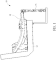
- FIG. 1 is a diagram of an infant car seat 10 and a vehicle seat 12 according to an embodiment of the present invention.
- FIG. 2 is a diagram of the infant car seat 10 in an operation mode according to the embodiment of the present invention.
- FIG. 3 is a diagram of the infant car seat 10 in a storage mode according to the embodiment of the present invention.
- the infant car seat 10 can be fixed to the vehicle seat 12 and has a safety seat for protecting the child.
- the infant car seat 10 can include a seat base 14 and a stability leg 16.
- the seat base 14 can be detachably fixed to the vehicle seat 12 via a latch mechanism, which is not shown in the figure.
- the stability leg 16 can be rotatably disposed under the seat base 14 for abutting against a vehicle floor.
- the stability leg 16 can be unfolded to switch the infant car seat 10 in the operation mode, as shown in FIG. 1 and FIG. 2 ; the stability leg 16 further can be folded to switch the infant car seat 10 in the storage mode, as shown in FIG. 3 .
- FIG. 4 is a diagram of the stability leg 16 according to the embodiment of the present invention.
- the stability leg 16 can include an upper leg tube 18, a lower leg tube 20, a rotary member 22, a first latch 24 and a second latch 26.
- the lower leg tube 20 and the second latch 26 may be optional units and can be omitted in some possible embodiment.
- the upper leg tube 18 can have at least one opening 28, and the rotary member 22 can be movably disposed on the upper leg tube 18, and the first latch 24 can be disposed on the rotary member 22.
- the first latch 24 can be detachably engaged with the opening 28 to constrain a movement between the rotary member 22 and the upper leg tube 18, so as to adjust a length of the stability leg 16.
- the lower leg tube 20 can be slidably assembled with the upper leg tube 18 and have at least one hole 30, and the second latch 26 can be disposed on the upper leg tube 18.
- the second latch 26 can detachably engage with the hole 30 to constrain a movement between the upper leg tube 18 and the lower leg tube 20, for adjusting the length of the stability leg 16.
- the rotary member 22 can include a pivoting portion 32 and an encircling portion 34.
- the pivoting portion 32 can be rotatably connected to the seat base 14, which means the stability leg 16 can be folded and unfolded relative to the seat base 14 via the pivoting portion 32.
- the encircling portion 34 can be connected to the pivoting portion 32 and slidably disposed on the upper leg tube 18.
- the upper leg tube 18 and/or the lower leg tube 20 can be pushed or pulled to change relative position between the encircling portion 34 of the rotary member 22 and the upper leg tube 18.
- FIG. 5 is a diagram of a part of the infant car seat 10 in the operation mode according to the embodiment of the present invention.
- FIG. 6 is a diagram of the part of the infant car seat 10 in the storage mode according to the embodiment of the present invention.
- the seat base 14 can include a support frame 36, and the rotary member 22 can further include a contacting portion 38.
- the stability leg 16 is unfolded, and the contacting portion 38 can abut against the support frame 36 to constrain a further rotation of the stability leg 16 relative to the seat base 14.
- the stability leg 16 is folded, and the contacting portion 38 can be away from the support frame 36.
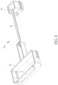
- FIG. 7 is a diagram of a release actuator 40 of the seat base 14 according to the embodiment of the present invention.
- FIG. 8 is a diagram of the release actuator 40 in another view according to the embodiment of the present invention.
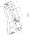
- FIG. 9 is a diagram of a part of the seat base 14 according to the embodiment of the present invention.
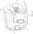
- FIG. 10 is a diagram of another part of the seat base 14 according to the embodiment of the present invention.
- the release actuator 40 can be operated to lock the stability leg 16 to steady the stability leg 16 in the storage mode.
- the release actuator 40 can include a handle portion 42, a locking portion 44 and a connection portion 46 connected to each other.
- the connection portion 46 can be disposed between the handle portion 42 and the locking portion 44.
- the handle portion 42 can be movably disposed on the seat base 14.
- the locking portion 44 can be engaged with or disengaged from a locked slot 45 formed on a lowest part of the stability leg 16.
- Two ends of the connection portion 46 can be respectively assembled with the handle portion 42 and the locking portion 44 in a movable manner.
- a first resilient component 48 can be disposed between the handle portion 42 and the seat base 14, and a second resilient component 50 can be disposed between the locking portion 44 and the seat base 14. If an external force is applied to the handle portion 42 for pulling out, the connection portion 46 can be driven by the handle portion 42 to pull out the locking portion 44 for disengaging the release actuator 40 from the stability leg 16. If the external force is removed, a resilient recovering force of the first resilient component 48 can move the handle portion 42 into the seat base 14, and a resilient recovering force of the second resilient component 50 can move the locking portion 44 back to an initial position.
- the seat base 14 can include a reclined foot 52, and the release actuator 40 can be movably disposed inside the reclined foot 52. If a height of the infant car seat 10 is intending to change, the reclined foot 52 can be rotated to protrude from or get back into a housing 54 of the seat base 14, and the first resilient component 48 can be deformed to adjust the connection portion 46, for allowing motion of the handle portion 42 due to rotation of the reclined foot 52, and keeping the locking portion 44 stably engaged with the stability leg 16.
- the connection portion 46 may be a flexible strap or solid material.
- the locking portion 44 can have a sunken structure 56.
- the external force may be applied to the sunken structure 56 of the locking portion 44 for pulling out, and the locking portion 44 can be disengaged from the stability leg 16.
- the resilient recovering force of the second resilient component 50 can move the locking portion 44 back to the initial position, for engaging with the stability leg 16.
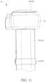
- FIG. 11 is a diagram of the stability leg 16 in a downward mode according to the embodiment of the present invention.
- FIG. 12 is a diagram of the stability leg 16 in an upward mode according to the embodiment of the present invention.
- the upper leg tube 18 can further include a tube body 58, a first blocker 60 and a second blocker 62.
- the first blocker 60 can be disposed on a top section of the tube body 58.
- the second blocker 62 can be disposed on a middle section of the tube body 58.
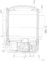
- FIG. 13 is a diagram of the upper leg tube 18, the rotary member 22 and the first latch 24 in a locking mode according to the embodiment of the present invention.
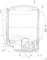
- FIG. 14 is a diagram of the upper leg tube 18, the rotary member 22 and the first latch 24 in an unlocking mode according to the embodiment of the present invention.
- the first latch 24 can include a first housing 64, a first button 66, a first lock 68 and a first recovering component 70.
- the first button 66 can be movably disposed on the first housing 64.
- the first lock 68 can be movably connected to the first button 66 and disposed inside the first housing 64.
- the first recovering component 70 can be disposed between the first button 66 and the first housing 64, or between the first lock 68 and the first housing 64. If the external force is applied to the first button 66, the first button 66 can be moved to actuate and disengage the first lock 68 from the opening 28 on the upper leg tube 18. If the external force is removed, a resilient recovering force of the first recovering component 70 can move and engage the first lock 68 with the opening 28 on the upper leg tube 18.
- the first button 66 can be moved inside the first housing 64 in a first direction D1
- the first lock 68 can be moved inside the first housing 64 in a second direction D2.
- the first direction D1 can be perpendicular to the second direction D2 according to structural design of the first button 66 and the first lock 68.
- the first button 66 can include a first engaging portion 72
- the first lock 68 can include a second engaging portion 74 movably assembled with the first engaging portion 72.
- the first engaging portion 72 and the second engaging portion 74 respectively can be a pin and a slotted structure.
- a structural direction of the slotted structure can be intersected with the first direction D1 and the second direction D2, so that relative motion between the first engaging portion 72 and the second engaging portion 74 can transform the external force in the first direction D1 into a pushing force applied to the first lock 68 in the second direction D2.
- the first button 66 may be turned to the left at ninety degrees, so the first button 66 can be moved in the first direction D1 similar to the first lock 68 moved in the second direction D2, and a structural length direction of the first button 66 can be parallel to a structural length direction of the first lock 68, which is not shown in the figures.
- the external force can push the first button 66 from the left to the right, to actuate and engage the first lock 68 with the opening 28 on the upper leg tube 18; when the external force is removed, the resilient recovering force of the first recovering component 70 can move and disengage the first lock 68 from the opening 28 on the upper leg tube 18.
- the first button 66 may be rotated in a clockwise direction or in a counterclockwise direction for actuating the first lock 68, which depends on a design demand, and a detailed description is omitted herein for simplicity.
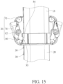
- FIG. 15 is a diagram of the upper leg tube 18, the lower leg tube 20 and the second latch 26 in the lock mode according to the embodiment of the present invention.
- FIG. 16 is a diagram of the upper leg tube 18, the lower leg tube 20 and the second latch 26 in the unlock mode according to the embodiment of the present invention.
- the second latch 26 can include a second housing 76, a second button 78, a second lock 80 and a second recovering component 82.
- the second button 78 can be movably disposed inside the second housing 76.
- the second lock 80 can be connected to the second button 78 and movably disposed inside the second housing 76.
- the second recovering component 82 can be disposed between the second housing 76 and the second button 78, or between the second housing 76 and the second lock 80.
- the second button 78 can be rotatably disposed inside the second housing 76.
- a part of the second button 78 can be protruded from the second housing 76, and the other part of the second button 78 can be accommodated inside the second housing 76 to abut against the second lock 80 in a detachable manner or in an undetachable manner. If the external force is applied to the second button 78, the second button 78 can be rotated in the counterclockwise direction to drive and disengage the second lock 80 from the hole 30 on the lower leg tube 20, and then the lower leg tube 20 can be slid relative to the upper leg tube 18, as conditions shown in FIG. 15 to FIG. 16 .
- a resilient recovering force of the second recovering component 82 can rotate the second button 78 in the clockwise direction, and the second lock 80 can be driven to pierce through the upper leg tube 18 and engage with the hole 30 on the lower leg tube 20; thus, the lower leg tube 20 cannot be slid relative to the upper leg tube 18, as conditions shown in FIG. 16 to FIG. 15 .
- the resilient recovering force of the second recovering component 82 may rotate the second lock 80 for engaging the second lock 80 with the hole 30 on the lower leg tube 20.
- the second button 78 and the second lock 80 may be set as linear slide design; for example, the second button 78 may be pushed or pulled to move in a straight direction, and the second lock 80 may be actuated by the second button 78 to move in another straight direction similar to or different from the foresaid straight direction.
- the second lock 80 of the second latch 26 can have a specifically inclined guiding structure 84 disposed on a front end of the second lock 80.
- the inclined guiding structure 84 can be pressed by the downwardly moved lower leg tube 20 to disengage the second lock 80 from the hole 30 on the lower leg tube 20.
- the stability leg 16 can be stretched by at least two ways. One way is pulling down on the lower leg tube 20; the second lock 80 can be pressed by the lower leg tube 20 to disengage from the lower leg tube 20, and then the lower leg tube 20 can be downward moved relative to the upper leg tube 18. Another way is pressing the second button 78; the second button 78 can be rotated or shifted to actuate disengagement of the second lock 80 and the lower leg tube 20.
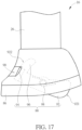
- FIG. 17 is a side view of a bottom of the stability leg 16 in a non-contact mode according to the embodiment of the present invention.
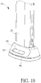
- FIG. 18 is a front view of the stability leg 16 in the non-contact mode according to the embodiment of the present invention.
- FIG. 19 is a side view of the bottom of the stability leg 16 in a contact mode according to the embodiment of the present invention.
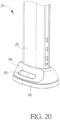
- FIG. 20 is a front view of the stability leg 16 in the contact mode according to the embodiment of the present invention.
- the stability leg 16 can further include a foot housing 86 and an indicator 88.
- the foot housing 86 can be disposed on a bottom of the lower leg tube 20, and have a window 90 formed on a front surface of the foot housing 86.
- the indicator 88 can include a main body 92, a first indication mark 94, a second indication mark 96 and an elastic component 98.
- the main body 92 can be movably disposed inside the foot housing 86.
- the first indication mark 94 and the second indication mark 96 can be disposed on respective positions on the main body 92.
- the elastic component 98 can be disposed between the main body 92 and the foot housing 86.
- the main body 92 can be disposed inside the foot housing 86 in a rotatable manner or in a slidable manner.
- the main body 92 is rotatable inside the foot housing 86.
- the main body 92 can have a first end 921 and a second end 922 opposite to each other.
- the first end 921 can be protruded from or accommodated inside a bottom of the foot housing 86 according to motion of the main body 92.
- the first indication mark 94 can be a red color mark formed on a lower position on the second end 922 of the main body 92
- the second indication mark 96 can be a green color mark formed on an upper position on the second end 922 of the man body 92.
- the first end 921 can be protruded from the bottom of the foot housing 86, and the second end 922 can be located at high position to align the first indication mark 94 with the window 90, as shown in FIG. 17 and FIG. 18 ; the exposed red color mark represents the infant car seat 10 is in an incorrect installed mode.
- the first end 921 can be rotated in the counterclockwise direction by pressure to accommodate inside the bottom of the foot housing 86, and the second end 922 can be moved downward to align the second indication mark 96 with the window 90, as shown in FIG. 19 and FIG.
- the exposed green color mark represents the infant car seat 10 is in a correct installed mode.
- a resilient recovering force of the elastic component 98 can rotate the main body 92 in the clockwise direction to align the first indication mark 94 with the window 90.
- an amount of the opening 28 can be less than an amount of the hole 30, so the first latch 24 can be used as gross adjustment, and the second latch 26 can be used as fine adjustment.
- Relative motion between the first latch 24 and the upper leg tube 18 can be executed for a start to rapidly extend the indicator 88 close to the vehicle floor; then, relative motion between the second latch 26 and the lower leg tube 20 can be executed to abut the indicator 88 against the vehicle floor tightly.
- the gross adjustment and the fine adjustment can be executed simultaneously or individually in accordance with an operation custom.
- the stability leg has the upper leg tube and the lower leg tube slidably assembled with each other.
- the first latch is used to constrain the relative movement between the upper leg tube and the rotary member
- the second latch is used to constrain the relative movement between the upper leg tube and the lower leg tube.
- the gross adjustment of the stability leg can lock the upper leg tube in an upper position for installing the infant car seat in a shorter and center vehicle seat, and further lock the upper leg tube in a lower position for installing the infant car seat in a taller and outboard vehicle seat
- the fine adjustment of the stability leg can lock the lower leg tube via one of the holes on the lower leg tube to change an extended length of the stability leg.
- the present application can also be defined by the following points:
Landscapes
- Engineering & Computer Science (AREA)
- Mechanical Engineering (AREA)
- General Engineering & Computer Science (AREA)
- Health & Medical Sciences (AREA)
- Child & Adolescent Psychology (AREA)
- General Health & Medical Sciences (AREA)
- Aviation & Aerospace Engineering (AREA)
- Transportation (AREA)
- Seats For Vehicles (AREA)
- Carriages For Children, Sleds, And Other Hand-Operated Vehicles (AREA)
Abstract
Description
- The present invention relates to an infant car seat with an adjustable and easy-to-operation function.
- An infant car seat is used to transport and protect infants in the vehicle. When the infant car seat is installed in the vehicle, a car seat base is secured to the vehicle via a latch belt or a vehicle belt, and the car seat base ensures the infant car seat is stably installed in the vehicle. The infant car seat further disposes a stability leg on the car seat base to protect the infants in the event of a vehicle collision. The car seat base is held against the floor of the vehicle via the stability leg, to prevent the car seat base from accidental rotation relative to the vehicle seat resulted from frontal collision. The conventional stability leg includes two leg tubes and one latch, and the latch constrains relative motion between the two leg tubes. Therefore, the conventional stability leg cannot provide multi-phase adjustment for the infant car seat.
- This in mind, the present invention aims at providing an infant car seat and a release actuator with an adjustable and easy-to-operation function for solving above drawbacks.
- This is achieved by an infant car seat according to claim 1. The dependent claims pertain to corresponding further developments and improvements.
- As will be seen more clearly from the detailed description following below, the claimed infant car seat includes a seat base and a stability leg. The stability leg is rotatably disposed under the seat base. The stability leg includes an upper leg tube, a rotary member and a first latch. The upper leg tube includes at least one opening. The rotary member includes a pivoting portion and an encircling portion. The pivoting portion is rotatably connected to the seat base. The encircling portion is connected to the pivoting portion and slidably disposed on the upper leg tube. The first latch is disposed on the rotary member, and adapted to detachably engage with the at least one opening for constraining a movement between the rotary member and the upper leg tube.
- In the following, the invention is further illustrated by way of example, taking reference to the accompanying drawings. Thereof:
-
FIG. 1 is a diagram of an infant car seat and a vehicle seat according to an embodiment of the present invention, -
FIG. 2 is a diagram of the infant car seat in an operation mode according to the embodiment of the present invention, -
FIG. 3 is a diagram of the infant car seat in a storage mode according to the embodiment of the present invention, -
FIG. 4 is a diagram of a stability leg according to the embodiment of the present invention, -
FIG. 5 is a diagram of a part of the infant car seat in the operation mode according to the embodiment of the present invention, -
FIG. 6 is a diagram of the part of the infant car seat in the storage mode according to the embodiment of the present invention, -
FIG. 7 is a diagram of a release actuator of a seat base according to the embodiment of the present invention, -
FIG. 8 is a diagram of the release actuator in another view according to the embodiment of the present invention, -
FIG. 9 is a diagram of a part of the seat base according to the embodiment of the present invention, -
FIG. 10 is a diagram of another part of the seat base according to the embodiment of the present invention, -
FIG. 11 is a diagram of the stability leg in a downward mode according to the embodiment of the present invention, -
FIG. 12 is a diagram of the stability leg in an upward mode according to the embodiment of the present invention, -
FIG. 13 is a diagram of an upper leg tube, a rotary member and a first latch in a locking mode according to the embodiment of the present invention, -
FIG. 14 is a diagram of the upper leg tube, the rotary member and the first latch in an unlocking mode according to the embodiment of the present invention, -
FIG. 15 is a diagram of the upper leg tube, the lower leg tube and the second latch in the lock mode according to the embodiment of the present invention, -
FIG. 16 is a diagram of the upper leg tube, the lower leg tube and the second latch in the unlock mode according to the embodiment of the present invention, -
FIG. 17 is a side view of a bottom of the stability leg in a non-contact mode according to the embodiment of the present invention, -
FIG. 18 is a front view of the stability leg in the non-contact mode according to the embodiment of the present invention, -
FIG. 19 is a side view of the bottom of the stability leg in a contact mode according to the embodiment of the present invention, and -
FIG. 20 is a front view of the stability leg in the contact mode according to the embodiment of the present invention. - Please refer to
FIG. 1 to FIG. 3 .FIG. 1 is a diagram of aninfant car seat 10 and avehicle seat 12 according to an embodiment of the present invention.FIG. 2 is a diagram of theinfant car seat 10 in an operation mode according to the embodiment of the present invention.FIG. 3 is a diagram of theinfant car seat 10 in a storage mode according to the embodiment of the present invention. Theinfant car seat 10 can be fixed to thevehicle seat 12 and has a safety seat for protecting the child. Theinfant car seat 10 can include aseat base 14 and astability leg 16. Theseat base 14 can be detachably fixed to thevehicle seat 12 via a latch mechanism, which is not shown in the figure. Thestability leg 16 can be rotatably disposed under theseat base 14 for abutting against a vehicle floor. Thestability leg 16 can be unfolded to switch theinfant car seat 10 in the operation mode, as shown inFIG. 1 andFIG. 2 ; thestability leg 16 further can be folded to switch theinfant car seat 10 in the storage mode, as shown inFIG. 3 . - Please refer to
FIG. 4. FIG. 4 is a diagram of thestability leg 16 according to the embodiment of the present invention. Thestability leg 16 can include anupper leg tube 18, alower leg tube 20, arotary member 22, afirst latch 24 and asecond latch 26. Thelower leg tube 20 and thesecond latch 26 may be optional units and can be omitted in some possible embodiment. For example, theupper leg tube 18 can have at least one opening 28, and therotary member 22 can be movably disposed on theupper leg tube 18, and thefirst latch 24 can be disposed on therotary member 22. Thefirst latch 24 can be detachably engaged with the opening 28 to constrain a movement between therotary member 22 and theupper leg tube 18, so as to adjust a length of thestability leg 16. - In the embodiment, the
lower leg tube 20 can be slidably assembled with theupper leg tube 18 and have at least onehole 30, and thesecond latch 26 can be disposed on theupper leg tube 18. Thesecond latch 26 can detachably engage with thehole 30 to constrain a movement between theupper leg tube 18 and thelower leg tube 20, for adjusting the length of thestability leg 16. Therotary member 22 can include apivoting portion 32 and anencircling portion 34. Thepivoting portion 32 can be rotatably connected to theseat base 14, which means thestability leg 16 can be folded and unfolded relative to theseat base 14 via thepivoting portion 32. Theencircling portion 34 can be connected to thepivoting portion 32 and slidably disposed on theupper leg tube 18. Theupper leg tube 18 and/or thelower leg tube 20 can be pushed or pulled to change relative position between the encirclingportion 34 of therotary member 22 and theupper leg tube 18. - Please refer to
FIG. 5 andFIG. 6 .FIG. 5 is a diagram of a part of theinfant car seat 10 in the operation mode according to the embodiment of the present invention.FIG. 6 is a diagram of the part of theinfant car seat 10 in the storage mode according to the embodiment of the present invention. Theseat base 14 can include asupport frame 36, and therotary member 22 can further include a contactingportion 38. As shown inFIG. 5 , thestability leg 16 is unfolded, and the contactingportion 38 can abut against thesupport frame 36 to constrain a further rotation of thestability leg 16 relative to theseat base 14. As shown inFIG. 6 , thestability leg 16 is folded, and the contactingportion 38 can be away from thesupport frame 36. - Please refer to
FIG.2 andFIG. 7 toFIG. 10 .FIG. 7 is a diagram of arelease actuator 40 of theseat base 14 according to the embodiment of the present invention.FIG. 8 is a diagram of therelease actuator 40 in another view according to the embodiment of the present invention.FIG. 9 is a diagram of a part of theseat base 14 according to the embodiment of the present invention.FIG. 10 is a diagram of another part of theseat base 14 according to the embodiment of the present invention. Therelease actuator 40 can be operated to lock thestability leg 16 to steady thestability leg 16 in the storage mode. Therelease actuator 40 can include ahandle portion 42, a lockingportion 44 and aconnection portion 46 connected to each other. Theconnection portion 46 can be disposed between thehandle portion 42 and the lockingportion 44. - The
handle portion 42 can be movably disposed on theseat base 14. The lockingportion 44 can be engaged with or disengaged from a lockedslot 45 formed on a lowest part of thestability leg 16. Two ends of theconnection portion 46 can be respectively assembled with thehandle portion 42 and the lockingportion 44 in a movable manner. In addition, a firstresilient component 48 can be disposed between thehandle portion 42 and theseat base 14, and a secondresilient component 50 can be disposed between the lockingportion 44 and theseat base 14. If an external force is applied to thehandle portion 42 for pulling out, theconnection portion 46 can be driven by thehandle portion 42 to pull out the lockingportion 44 for disengaging therelease actuator 40 from thestability leg 16. If the external force is removed, a resilient recovering force of the firstresilient component 48 can move thehandle portion 42 into theseat base 14, and a resilient recovering force of the secondresilient component 50 can move the lockingportion 44 back to an initial position. - Moreover, the
seat base 14 can include a reclinedfoot 52, and therelease actuator 40 can be movably disposed inside the reclinedfoot 52. If a height of theinfant car seat 10 is intending to change, the reclinedfoot 52 can be rotated to protrude from or get back into ahousing 54 of theseat base 14, and the firstresilient component 48 can be deformed to adjust theconnection portion 46, for allowing motion of thehandle portion 42 due to rotation of the reclinedfoot 52, and keeping the lockingportion 44 stably engaged with thestability leg 16. Theconnection portion 46 may be a flexible strap or solid material. - In a possible situation, the locking
portion 44 can have asunken structure 56. The external force may be applied to thesunken structure 56 of the lockingportion 44 for pulling out, and the lockingportion 44 can be disengaged from thestability leg 16. When the external force is removed, the resilient recovering force of the secondresilient component 50 can move the lockingportion 44 back to the initial position, for engaging with thestability leg 16. - Please refer to
FIG. 11 andFIG. 12 .FIG. 11 is a diagram of thestability leg 16 in a downward mode according to the embodiment of the present invention.FIG. 12 is a diagram of thestability leg 16 in an upward mode according to the embodiment of the present invention. Theupper leg tube 18 can further include atube body 58, afirst blocker 60 and asecond blocker 62. Thefirst blocker 60 can be disposed on a top section of thetube body 58. Thesecond blocker 62 can be disposed on a middle section of thetube body 58. When theupper leg tube 18 is moved downward relative to therotary member 22, thefirst blocker 60 can abut against therotary member 22 to constrain a downward motion of theupper leg tube 18. When theupper leg tube 18 is moved upward relative to therotary member 22, thesecond blocker 62 can abut against therotary member 22 to constrain upward motion of theupper leg tube 18. - Please refer to
FIG. 11 to FIG. 14 .FIG. 13 is a diagram of theupper leg tube 18, therotary member 22 and thefirst latch 24 in a locking mode according to the embodiment of the present invention.FIG. 14 is a diagram of theupper leg tube 18, therotary member 22 and thefirst latch 24 in an unlocking mode according to the embodiment of the present invention. Thefirst latch 24 can include afirst housing 64, afirst button 66, afirst lock 68 and a first recoveringcomponent 70. Thefirst button 66 can be movably disposed on thefirst housing 64. Thefirst lock 68 can be movably connected to thefirst button 66 and disposed inside thefirst housing 64. Thefirst recovering component 70 can be disposed between thefirst button 66 and thefirst housing 64, or between thefirst lock 68 and thefirst housing 64. If the external force is applied to thefirst button 66, thefirst button 66 can be moved to actuate and disengage thefirst lock 68 from theopening 28 on theupper leg tube 18. If the external force is removed, a resilient recovering force of the first recoveringcomponent 70 can move and engage thefirst lock 68 with theopening 28 on theupper leg tube 18. - In the embodiment, the
first button 66 can be moved inside thefirst housing 64 in a first direction D1, and thefirst lock 68 can be moved inside thefirst housing 64 in a second direction D2. The first direction D1 can be perpendicular to the second direction D2 according to structural design of thefirst button 66 and thefirst lock 68. For example, thefirst button 66 can include a first engagingportion 72, and thefirst lock 68 can include a second engagingportion 74 movably assembled with the first engagingportion 72. The first engagingportion 72 and the second engagingportion 74 respectively can be a pin and a slotted structure. A structural direction of the slotted structure can be intersected with the first direction D1 and the second direction D2, so that relative motion between the first engagingportion 72 and the second engagingportion 74 can transform the external force in the first direction D1 into a pushing force applied to thefirst lock 68 in the second direction D2. - In other possible embodiments, the
first button 66 may be turned to the left at ninety degrees, so thefirst button 66 can be moved in the first direction D1 similar to thefirst lock 68 moved in the second direction D2, and a structural length direction of thefirst button 66 can be parallel to a structural length direction of thefirst lock 68, which is not shown in the figures. The external force can push thefirst button 66 from the left to the right, to actuate and engage thefirst lock 68 with theopening 28 on theupper leg tube 18; when the external force is removed, the resilient recovering force of the first recoveringcomponent 70 can move and disengage thefirst lock 68 from theopening 28 on theupper leg tube 18. Besides, thefirst button 66 may be rotated in a clockwise direction or in a counterclockwise direction for actuating thefirst lock 68, which depends on a design demand, and a detailed description is omitted herein for simplicity. - Please refer to
FIG. 15 andFIG. 16 .FIG. 15 is a diagram of theupper leg tube 18, thelower leg tube 20 and thesecond latch 26 in the lock mode according to the embodiment of the present invention.FIG. 16 is a diagram of theupper leg tube 18, thelower leg tube 20 and thesecond latch 26 in the unlock mode according to the embodiment of the present invention. Thesecond latch 26 can include asecond housing 76, a second button 78, asecond lock 80 and asecond recovering component 82. The second button 78 can be movably disposed inside thesecond housing 76. Thesecond lock 80 can be connected to the second button 78 and movably disposed inside thesecond housing 76. Thesecond recovering component 82 can be disposed between thesecond housing 76 and the second button 78, or between thesecond housing 76 and thesecond lock 80. - In the embodiment, the second button 78 can be rotatably disposed inside the
second housing 76. A part of the second button 78 can be protruded from thesecond housing 76, and the other part of the second button 78 can be accommodated inside thesecond housing 76 to abut against thesecond lock 80 in a detachable manner or in an undetachable manner. If the external force is applied to the second button 78, the second button 78 can be rotated in the counterclockwise direction to drive and disengage thesecond lock 80 from thehole 30 on thelower leg tube 20, and then thelower leg tube 20 can be slid relative to theupper leg tube 18, as conditions shown inFIG. 15 to FIG. 16 . If the external force is removed, a resilient recovering force of thesecond recovering component 82 can rotate the second button 78 in the clockwise direction, and thesecond lock 80 can be driven to pierce through theupper leg tube 18 and engage with thehole 30 on thelower leg tube 20; thus, thelower leg tube 20 cannot be slid relative to theupper leg tube 18, as conditions shown inFIG. 16 to FIG. 15 . - In some possible embodiments, the resilient recovering force of the
second recovering component 82 may rotate thesecond lock 80 for engaging thesecond lock 80 with thehole 30 on thelower leg tube 20. Besides, the second button 78 and thesecond lock 80 may be set as linear slide design; for example, the second button 78 may be pushed or pulled to move in a straight direction, and thesecond lock 80 may be actuated by the second button 78 to move in another straight direction similar to or different from the foresaid straight direction. - The
second lock 80 of thesecond latch 26 can have a specifically inclined guidingstructure 84 disposed on a front end of thesecond lock 80. When thesecond lock 80 is inserted into thehole 30 on thelower leg tube 20, theinclined guiding structure 84 can be pressed by the downwardly movedlower leg tube 20 to disengage thesecond lock 80 from thehole 30 on thelower leg tube 20. Thestability leg 16 can be stretched by at least two ways. One way is pulling down on thelower leg tube 20; thesecond lock 80 can be pressed by thelower leg tube 20 to disengage from thelower leg tube 20, and then thelower leg tube 20 can be downward moved relative to theupper leg tube 18. Another way is pressing the second button 78; the second button 78 can be rotated or shifted to actuate disengagement of thesecond lock 80 and thelower leg tube 20. - Please refer to
FIG. 17 to FIG. 20 .FIG. 17 is a side view of a bottom of thestability leg 16 in a non-contact mode according to the embodiment of the present invention.FIG. 18 is a front view of thestability leg 16 in the non-contact mode according to the embodiment of the present invention.FIG. 19 is a side view of the bottom of thestability leg 16 in a contact mode according to the embodiment of the present invention.FIG. 20 is a front view of thestability leg 16 in the contact mode according to the embodiment of the present invention. - The
stability leg 16 can further include afoot housing 86 and anindicator 88. Thefoot housing 86 can be disposed on a bottom of thelower leg tube 20, and have awindow 90 formed on a front surface of thefoot housing 86. Theindicator 88 can include amain body 92, afirst indication mark 94, asecond indication mark 96 and anelastic component 98. Themain body 92 can be movably disposed inside thefoot housing 86. Thefirst indication mark 94 and thesecond indication mark 96 can be disposed on respective positions on themain body 92. Theelastic component 98 can be disposed between themain body 92 and thefoot housing 86. - The
main body 92 can be disposed inside thefoot housing 86 in a rotatable manner or in a slidable manner. In the embodiment, themain body 92 is rotatable inside thefoot housing 86. Themain body 92 can have afirst end 921 and asecond end 922 opposite to each other. Thefirst end 921 can be protruded from or accommodated inside a bottom of thefoot housing 86 according to motion of themain body 92. Thefirst indication mark 94 can be a red color mark formed on a lower position on thesecond end 922 of themain body 92, and thesecond indication mark 96 can be a green color mark formed on an upper position on thesecond end 922 of theman body 92. - If the
stability leg 16 is suspended and does not abut against the vehicle floor, thefirst end 921 can be protruded from the bottom of thefoot housing 86, and thesecond end 922 can be located at high position to align thefirst indication mark 94 with thewindow 90, as shown inFIG. 17 andFIG. 18 ; the exposed red color mark represents theinfant car seat 10 is in an incorrect installed mode. If thestability leg 16 is lowered to abut against the vehicle floor, thefirst end 921 can be rotated in the counterclockwise direction by pressure to accommodate inside the bottom of thefoot housing 86, and thesecond end 922 can be moved downward to align thesecond indication mark 96 with thewindow 90, as shown inFIG. 19 andFIG. 20 ; the exposed green color mark represents theinfant car seat 10 is in a correct installed mode. When thestability leg 16 is lifted, a resilient recovering force of theelastic component 98 can rotate themain body 92 in the clockwise direction to align thefirst indication mark 94 with thewindow 90. - As shown in
FIG. 4 andFIG. 11 toFIG. 16 , an amount of theopening 28 can be less than an amount of thehole 30, so thefirst latch 24 can be used as gross adjustment, and thesecond latch 26 can be used as fine adjustment. Relative motion between thefirst latch 24 and theupper leg tube 18 can be executed for a start to rapidly extend theindicator 88 close to the vehicle floor; then, relative motion between thesecond latch 26 and thelower leg tube 20 can be executed to abut theindicator 88 against the vehicle floor tightly. When theinfant car seat 10 is folded, the gross adjustment and the fine adjustment can be executed simultaneously or individually in accordance with an operation custom. - In the embodiment of the present invention, the stability leg has the upper leg tube and the lower leg tube slidably assembled with each other. The first latch is used to constrain the relative movement between the upper leg tube and the rotary member, and the second latch is used to constrain the relative movement between the upper leg tube and the lower leg tube. The gross adjustment of the stability leg can lock the upper leg tube in an upper position for installing the infant car seat in a shorter and center vehicle seat, and further lock the upper leg tube in a lower position for installing the infant car seat in a taller and outboard vehicle seat; the fine adjustment of the stability leg can lock the lower leg tube via one of the holes on the lower leg tube to change an extended length of the stability leg.
The present application can also be defined by the following points: - 1. An infant car seat, the infant car seat characterized by:
- a seat base; and
- a stability leg rotatably disposed under the seat base, the stability leg comprising:
- an upper leg tube, comprising at least one opening;
- a rotary member, comprising:
- a pivoting portion rotatably connected to the seat base; and
- an encircling portion connected to the pivoting portion and slidably disposed on the upper leg tube; and
- a first latch disposed on the rotary member, and adapted to detachably engage with the at least one opening for constraining a movement between the rotary member and the upper leg tube.
- 2. The infant car seat of point 1, characterized in that the stability leg further comprises:
- a lower leg tube slidably assembled with the upper leg tube, and comprising at least one hole; and
- a second latch disposed on the upper leg tube, and adapted to detachably engage with the at least one hole for constraining a movement between the upper leg tube and the lower leg tube.
- 3. The infant car seat of point 1, characterized in that the seat base comprises a support frame, the rotary member further comprises a contacting portion adapted to abut against the support frame for constraining a rotation of the stability leg relative to the seat base in an operation mode.
- 4. The infant car seat of point 1, characterized in that the seat base comprises a release actuator adapted to lock the stability leg for steadying the stability leg in a storage mode.
- 5. The infant car seat of point 4, characterized in that the release actuator comprises a handle portion and a locking portion connected to each other, the locking portion is engaged with or disengaged from the stability leg, the handle portion is movably disposed on the seat base and adapted to be applied by an external force for disengaging the locking portion from the stability leg.
- 6. The infant car seat of point 5, characterized in that the release actuator further comprises a connection portion disposed between the handle portion and the locking portion, two ends of the connection portion are respectively assembled with the handle portion and the locking portion in a movable manner.
- 7. The infant car seat of point 6, characterized in that the release actuator further comprises a first resilient component disposed between the handle portion and the seat base, and further comprises a second resilient component disposed between the locking portion and the seat base.
- 8. The infant car seat of point 7, characterized in that the seat base comprises a reclined foot, the release actuator is movably disposed inside the reclined foot, the locking portion is engaged with the stability leg via deformation of the first resilient component when the handle portion is moved with rotation of the reclined foot.
- 9. The infant car seat of point 5, characterized in that the locking portion has a sunken structure adapted to be applied by an external force for disengaging the locking portion from the stability leg.
- 10. The infant car seat of point 1, characterized in that the upper leg tube further comprises a tube body, a first blocker and a second blocker, the first blocker is disposed on a top section of the tube body and adapted to constrain a downward motion of the upper leg tube relative to the rotary member, the second blocker is disposed on a middle section of the tube body and adapted to constrain an upward motion of the upper leg tube relative to the rotary member.
- 11. The infant car seat of point 1, characterized in that the first latch comprises a first housing, a first button and a first lock, the first button is movably disposed on the first housing, the first lock is movably connected to the first button and disposed inside the first housing for engaging with and disengaging from the at least one opening via motion of the first button.
- 12. The infant car seat of
point 11, characterized in that the first button is moved inside the first housing in a first direction, and the first lock is moved inside the first housing in a second direction similar to or different from the first direction. - 13. The infant car seat of
point 11, characterized in that the first latch further comprises a first recovering component disposed between the first housing and the first button, or between the first housing and the first lock. - 14. The infant car seat of
point 11, characterized in that the first button comprises a first engaging portion, and the first lock comprises a second engaging portion movably assembled with the first engaging portion. - 15. The infant car seat of
point 14, characterized in that the first engaging portion and the second engaging portion respectively are a pin and a slotted structure, a structural direction of the slotted structure is intersected with the first direction and the second direction. - 16. The infant car seat of point 2, characterized in that the second latch comprises a second housing, a second button and a second lock, the second button is movably disposed on the second housing, the second lock is connected to the second button and movably disposed inside the second housing for engaging with and disengaging from one of the at least one hole via rotation of the second button.
- 17. The infant car seat of
point 16, characterized in that the second latch further comprises a second recovering component disposed between the second housing and the second button. - 18. The infant car seat of
point 16, characterized in that the second lock is disengaged from the at least one hole via pulling down on the lower leg tube or pressing the second button. - 19. The infant car seat of point 2, characterized in that the stability leg further comprises:
a foot housing disposed on a bottom of the lower leg tube, the foot housing having a window; and an indicator, having a main body, a first indication mark and a second indication mark, the main body being movably disposed inside the foot housing, the first indication mark and the second indication mark being disposed on respective positions on the main body, one of the first indication mark and the second indication mark aligning with the window in response to motion of the main body relative to the foot housing. - 20. The infant car seat of point 19, characterized in that the main body has a first end and a second end opposite to each other, the first end is protruded from or accommodated inside a bottom of the foot housing according to motion of the main body, the first indication mark and the second indication mark are disposed on the second end.
- 21. The infant car seat of point 19, characterized in that the main body is disposed inside the foot housing in a rotatable manner or in a slidable manner.
- 22. The infant car seat of point 19, characterized in that the indicator further has an elastic component disposed between the main body and the foot housing.
- 23. A release actuator of engaging a stability leg with a seat base of an infant car seat, the release actuator characterized by:
- a locking portion adapted to engage with or disengage from the stability leg; and
- a handle portion connected to the locking portion and movably disposed on the seat base, the handle portion being adapted to be applied by an external force for disengaging the locking portion from the stability leg.
- 24. The release actuator of point 23, characterized in that the release actuator further comprises a connection portion disposed between the handle portion and the locking portion, two ends of the connection portion are respectively assembled with the handle portion and the locking portion in a movable manner.
- 25. The release actuator of
point 24, characterized in that the release actuator further comprises a first resilient component disposed between the handle portion and the seat base, and further comprises a second resilient component disposed between the locking portion and the seat base. - 26. The release actuator of point 25, characterized in that the seat base comprises a reclined foot, the release actuator is movably disposed inside the reclined foot, the locking portion is engaged with the stability leg via deformation of the first resilient component when the handle portion is moved with rotation of the reclined foot.
- 27. The release actuator of point 23, characterized in that the locking portion has a sunken structure adapted to be applied by an external force for disengaging the locking portion from the stability leg.
Claims (5)
- An infant car seat (10), comprising:a seat base (14), anda stability leg (16),characterized by a release actuator for engaging the stability leg (16) with the seat base (14),wherein the release actuator (40) comprises:a locking portion (44) adapted to engage releasably with a free end of the stability leg (16), anda handle portion (42) connected to the locking portion (44) and movably disposed on the seat base (14), the handle portion (42) being adapted to be applied by an external force for disengaging the locking portion (44) from the stability leg (16).
- The infant car seat (10) of claim 1, wherein the release actuator (40) further comprises a connection portion (46) disposed between the handle portion (42) and the locking portion (44), two ends of the connection portion (46) are respectively assembled with the handle portion (42) and the locking portion (44) in a movable manner.
- The infant car seat (10) of claim 2, wherein the release actuator (40) further comprises a first resilient component (48) disposed between the handle portion (42) and the seat base (14), and further comprises a second resilient component (50) disposed between the locking portion (44) and the seat base (14).
- The infant car seat (10) of claim 3, wherein the seat base (14) comprises a reclined foot (52), the release actuator (40) is movably disposed inside the reclined foot (52), the locking portion (44) is engaged with the stability leg (16) via deformation of the first resilient component (48) when the handle portion (42) is moved with rotation of the reclined foot (52).
- The infant car seat (10) of claim 1, wherein the locking portion (44) comprises a sunken structure (56) adapted to be applied by an external force for disengaging the locking portion (44) from the stability leg (16).
Applications Claiming Priority (2)
| Application Number | Priority Date | Filing Date | Title |
|---|---|---|---|
| US201962901544P | 2019-09-17 | 2019-09-17 | |
| EP20196670.2A EP3798050B1 (en) | 2019-09-17 | 2020-09-17 | Infant car seat and release actuator |
Related Parent Applications (1)
| Application Number | Title | Priority Date | Filing Date |
|---|---|---|---|
| EP20196670.2A Division EP3798050B1 (en) | 2019-09-17 | 2020-09-17 | Infant car seat and release actuator |
Publications (1)
| Publication Number | Publication Date |
|---|---|
| EP4159534A1 true EP4159534A1 (en) | 2023-04-05 |
Family
ID=72560464
Family Applications (2)
| Application Number | Title | Priority Date | Filing Date |
|---|---|---|---|
| EP22202114.9A Pending EP4159534A1 (en) | 2019-09-17 | 2020-09-17 | Infant car seat and release actuator |
| EP20196670.2A Active EP3798050B1 (en) | 2019-09-17 | 2020-09-17 | Infant car seat and release actuator |
Family Applications After (1)
| Application Number | Title | Priority Date | Filing Date |
|---|---|---|---|
| EP20196670.2A Active EP3798050B1 (en) | 2019-09-17 | 2020-09-17 | Infant car seat and release actuator |
Country Status (3)
| Country | Link |
|---|---|
| US (4) | US11345262B2 (en) |
| EP (2) | EP4159534A1 (en) |
| CN (2) | CN112519646B (en) |
Families Citing this family (11)
| Publication number | Priority date | Publication date | Assignee | Title |
|---|---|---|---|---|
| CN112519646B (en) | 2019-09-17 | 2023-05-30 | 明门瑞士股份有限公司 | Infant safety seat and seat base |
| EP4054890A4 (en) * | 2019-11-04 | 2024-06-12 | BabyArk LTD | CAR SEAT BASE WITH INSTALLATION GUIDE AND ANTI-BOUNCE LOCKING MECHANISM |
| EP4054901A4 (en) | 2019-11-04 | 2023-12-20 | BabyArk LTD | METHOD AND SYSTEMS FOR GENERATING TRAINING AND EXECUTION OF A MODEL FOR DETECTING SAFETY SEAT EVENTS |
| CN114981124B (en) | 2019-11-04 | 2025-02-25 | 婴儿方舟有限公司 | Side impact safety seat |
| CN114929513B (en) | 2019-11-04 | 2024-10-01 | 婴儿方舟有限公司 | Method and system for a safety seat |
| US11691543B2 (en) | 2020-04-14 | 2023-07-04 | Wonderland Switzerland Ag | Infant car seat and stability leg and release actuator |
| USD1074287S1 (en) | 2020-09-17 | 2025-05-13 | Wonderland Switzerland Ag | Base for infant car seat |
| CN115571029A (en) * | 2021-06-21 | 2023-01-06 | 明门(中国)幼童用品有限公司 | Safety seat |
| CN115703385A (en) * | 2021-08-09 | 2023-02-17 | 明门瑞士股份有限公司 | Connection adjustment mechanism and child carrier |
| CN115123033B (en) * | 2022-05-05 | 2024-04-05 | 好孩子儿童用品有限公司 | A safety seat |
| CN121404098A (en) * | 2024-07-26 | 2026-01-27 | 明门(中国)幼童用品有限公司 | Support devices and safety vehicles |
Citations (3)
| Publication number | Priority date | Publication date | Assignee | Title |
|---|---|---|---|---|
| EP2623368A1 (en) * | 2012-02-06 | 2013-08-07 | BP Children's Products HK Co., Limited | Fixing mechanism of child safety chair |
| WO2019019502A1 (en) | 2017-07-26 | 2019-01-31 | 珠海阳光儿童用品有限公司 | Support for child safety seat |
| CN109398174A (en) * | 2017-08-18 | 2019-03-01 | 宝钜儿童用品香港股份有限公司 | Automobile safety seat and supporting leg device thereof |
Family Cites Families (49)
| Publication number | Priority date | Publication date | Assignee | Title |
|---|---|---|---|---|
| US4834403A (en) * | 1987-10-30 | 1989-05-30 | Yanus Theodore M | Combined infant car-seat and stroller |
| US4872692A (en) * | 1988-06-03 | 1989-10-10 | Prodigy Corp. | Convertible carriage with biased wheel retraction |
| US5385387A (en) | 1993-10-01 | 1995-01-31 | Lisco, Inc. | Child carrier with detachable base |
| US5772279A (en) * | 1995-08-31 | 1998-06-30 | Kolcraft Enterprises, Inc. | Coupling system for infant carrier to second support device |
| US6209957B1 (en) * | 1999-06-10 | 2001-04-03 | Britax Child Safety Inc. | Child safety seat |
| AU3556202A (en) * | 2002-04-19 | 2003-10-23 | Douglas K. Ziegler | Infant/child vehicle safety seat having improved ergonomics |
| NL1023422C2 (en) * | 2003-05-14 | 2004-11-16 | Maxi Miliaan Bv | Children's vehicle seat. |
| FR2864482B1 (en) | 2003-12-24 | 2006-03-03 | Peugeot Citroen Automobiles Sa | DEVICE FOR RETAINING A CHILD SEAT |
| US20080303321A1 (en) | 2004-05-08 | 2008-12-11 | Britax Excelsior Limited | Base for a Child Safety Support |
| US20070252067A1 (en) | 2006-04-26 | 2007-11-01 | Wade Lee | Locking Latch for Telescoping Tripod |
| CN2928580Y (en) | 2006-08-02 | 2007-08-01 | 明门实业股份有限公司 | Child car seat supports |
| EP1927502B1 (en) | 2006-11-28 | 2009-09-09 | Wonderland Nurserygoods Co., Ltd. | Child vehicle safety seat |
| US7908981B2 (en) | 2007-01-31 | 2011-03-22 | Michael Agee | Height adjustable table |
| DE202007013091U1 (en) | 2007-09-19 | 2008-01-24 | Kunz, Georg Ludwig | Fastening device for a child seat |
| US8141951B2 (en) | 2008-09-10 | 2012-03-27 | Excellerate Enterprise Co., Ltd. | Child safety seat |
| NL1036452C2 (en) | 2009-01-23 | 2010-07-26 | Maxi Miliaan Bv | A child vehicle seat as well as a chassis suitable for such a child vehicle seat. |
| DE202009001975U1 (en) | 2009-03-17 | 2009-05-28 | Curt Würstl Vermögensverwaltungs-Gmbh & Co. Kg | Seat anchoring element for child safety seats or baby carrier |
| CN102729854B (en) | 2011-04-11 | 2015-06-24 | 明门香港股份有限公司 | Supporting device and child safety seat with same |
| CA2882651C (en) * | 2011-04-15 | 2017-03-21 | Bp Children's Products Hk Co., Limited | Child safety seat |
| CN202071722U (en) | 2011-04-26 | 2011-12-14 | 中山市隆成日用制品有限公司 | Support frame warning device for safety seat base |
| CN103042953A (en) | 2011-10-11 | 2013-04-17 | 宝钜儿童用品香港股份有限公司 | Support foot safety indicator device |
| CN103507675B (en) * | 2012-06-28 | 2016-01-13 | 宝钜儿童用品香港股份有限公司 | Child car seat supporting device and child car safety seat |
| CN203237080U (en) | 2013-04-18 | 2013-10-16 | 中山市隆成日用制品有限公司 | Infant and Child Safety Seat Base Support Footstand Storage Mechanism |
| CN203267824U (en) | 2013-05-02 | 2013-11-06 | 中山市隆成日用制品有限公司 | Supporting frame color display mechanism with safety seat pedestal |
| US9480343B2 (en) * | 2013-06-14 | 2016-11-01 | Wonderland Nurserygoods Company Limited | Child high chair |
| CN203666434U (en) | 2013-12-19 | 2014-06-25 | 宝钜(中国)儿童用品有限公司 | Supporting device and safe child car seat provided with same |
| JP6356503B2 (en) | 2014-06-24 | 2018-07-11 | アップリカ・チルドレンズプロダクツ合同会社 | child seat |
| CN105329123B (en) | 2014-07-11 | 2018-05-04 | 宝钜儿童用品香港股份有限公司 | Adjustment mechanism and child safety seat with same |
| CN204020627U (en) | 2014-08-08 | 2014-12-17 | 麦克英孚(宁波)婴童用品有限公司 | Feet puts in place indication mechanism |
| CN204077432U (en) | 2014-09-05 | 2015-01-07 | 宁波市博林日用品制造有限公司 | A kind of supporting foot structure of child safety seat |
| CN104875636B (en) | 2015-06-12 | 2017-04-12 | 上海翼锐汽车科技有限公司 | Light supporting leg of child seat |
| DE202015104792U1 (en) | 2015-09-09 | 2015-12-01 | Cybex Gmbh | Child seat for attachment to a motor vehicle seat |
| JP6590673B2 (en) | 2015-12-10 | 2019-10-16 | アップリカ・チルドレンズプロダクツ合同会社 | child seat |
| CN205344586U (en) | 2016-02-02 | 2016-06-29 | 麦克英孚(宁波)婴童用品有限公司 | Safe seat supporting leg with bottom contact indicating device |
| KR101850833B1 (en) | 2016-09-13 | 2018-05-31 | 주식회사 쁘레베베 | Support leg and safety car seat for infant using the same |
| CN107826001B (en) | 2016-09-16 | 2020-05-22 | 明门瑞士股份有限公司 | Supporting leg and child safety seat assembly thereof |
| CN121588347A (en) | 2016-12-16 | 2026-03-03 | 索伦托治疗有限公司 | Application mechanism for fluid delivery device and method of use thereof |
| ES2806278T3 (en) | 2017-09-14 | 2021-02-17 | Britax Roemer Kindersicherheit Gmbh | Support leg for a child safety seat |
| CN109823242B (en) | 2017-11-23 | 2022-05-31 | 宝钜儿童用品香港股份有限公司 | Support foot set and child safety seat with cushioning structure |
| CN207697564U (en) | 2017-12-21 | 2018-08-07 | 浙江雅虎汽车部件有限公司 | Contact to earth indication mechanism for a kind of supporting leg bottom of child safety seat |
| CN108082012A (en) | 2017-12-21 | 2018-05-29 | 浙江雅虎汽车部件有限公司 | Contact to earth indication mechanism for a kind of supporting leg bottom of child safety seat |
| CN208359971U (en) | 2018-03-22 | 2019-01-11 | 浙江力合汽车用品有限公司 | The supporting leg of children's seat is to level display apparatus |
| US11097639B2 (en) | 2018-05-24 | 2021-08-24 | Wonderland Switzerland Ag | Support base for a child safety seat |
| CN208585134U (en) | 2018-06-26 | 2019-03-08 | 麦克英孚(宁波)婴童用品有限公司 | A kind of support leg mechanism with instruction function |
| CN210502383U (en) | 2019-07-02 | 2020-05-12 | 宁波惠尔顿婴童安全科技股份有限公司 | Child safety seat supporting leg structure with prompt function |
| CN112519646B (en) | 2019-09-17 | 2023-05-30 | 明门瑞士股份有限公司 | Infant safety seat and seat base |
| CN211543324U (en) | 2020-01-16 | 2020-09-22 | 扬州莱特斯婴童用品有限公司 | Supporting leg for child safety seat |
| US11691543B2 (en) | 2020-04-14 | 2023-07-04 | Wonderland Switzerland Ag | Infant car seat and stability leg and release actuator |
| CN114379433B (en) | 2020-10-22 | 2025-03-07 | 宝钜瑞士股份有限公司 | Indicator assembly for supporting foot device of safety seat and safety seat |
-
2020
- 2020-09-17 CN CN202010979091.3A patent/CN112519646B/en active Active
- 2020-09-17 EP EP22202114.9A patent/EP4159534A1/en active Pending
- 2020-09-17 CN CN202310521752.1A patent/CN116572805A/en active Pending
- 2020-09-17 EP EP20196670.2A patent/EP3798050B1/en active Active
- 2020-09-17 US US17/023,405 patent/US11345262B2/en active Active
-
2022
- 2022-04-21 US US17/726,264 patent/US11738668B2/en active Active
-
2023
- 2023-07-07 US US18/348,571 patent/US12291133B2/en active Active
-
2024
- 2024-10-30 US US18/932,218 patent/US20250050791A1/en active Pending
Patent Citations (3)
| Publication number | Priority date | Publication date | Assignee | Title |
|---|---|---|---|---|
| EP2623368A1 (en) * | 2012-02-06 | 2013-08-07 | BP Children's Products HK Co., Limited | Fixing mechanism of child safety chair |
| WO2019019502A1 (en) | 2017-07-26 | 2019-01-31 | 珠海阳光儿童用品有限公司 | Support for child safety seat |
| CN109398174A (en) * | 2017-08-18 | 2019-03-01 | 宝钜儿童用品香港股份有限公司 | Automobile safety seat and supporting leg device thereof |
Also Published As
| Publication number | Publication date |
|---|---|
| US20210078461A1 (en) | 2021-03-18 |
| US12291133B2 (en) | 2025-05-06 |
| US20220242281A1 (en) | 2022-08-04 |
| CN116572805A (en) | 2023-08-11 |
| CN112519646A (en) | 2021-03-19 |
| EP3798050B1 (en) | 2022-10-19 |
| CN112519646B (en) | 2023-05-30 |
| US20250050791A1 (en) | 2025-02-13 |
| US20240001818A1 (en) | 2024-01-04 |
| EP3798050A1 (en) | 2021-03-31 |
| US11345262B2 (en) | 2022-05-31 |
| US11738668B2 (en) | 2023-08-29 |
Similar Documents
| Publication | Publication Date | Title |
|---|---|---|
| EP4159534A1 (en) | Infant car seat and release actuator | |
| US12115890B2 (en) | Infant car seat and stability leg and release actuator | |
| KR102620204B1 (en) | Baby stroller with a folding mechanism triggered by a child carrier | |
| US7712765B2 (en) | Stroller having a single folding shaft | |
| EP3659858A1 (en) | Child safety seat | |
| US8393678B2 (en) | Infant child restraint system | |
| KR102924351B1 (en) | Child safety seats and seat bases | |
| EP4222019B1 (en) | Base structure adapted for a seat body of a child safety seat | |
| EP4234322B1 (en) | Backrest locking mechanism and child safety seat therewith | |
| EP4509355A1 (en) | Child safety seat | |
| TWI801886B (en) | Carrier body and child car seat therewith | |
| CN109515508B (en) | baby stroller | |
| CN113844525B (en) | Baby carriage and seat height adjusting mechanism thereof | |
| CN119218070A (en) | Adjustable front body protector and car seat | |
| CN220243338U (en) | Folding unlocking structure of folding baby carriage | |
| CN115649022B (en) | A knob-type child seat support leg | |
| EP3862248A1 (en) | Child stroller apparatus | |
| HK40104126A (en) | Infant car seat anchoring assembly with retractable foot | |
| CN120382341A (en) | Carrier and its positioning components |
Legal Events
| Date | Code | Title | Description |
|---|---|---|---|
| PUAI | Public reference made under article 153(3) epc to a published international application that has entered the european phase |
Free format text: ORIGINAL CODE: 0009012 |
|
| STAA | Information on the status of an ep patent application or granted ep patent |
Free format text: STATUS: THE APPLICATION HAS BEEN PUBLISHED |
|
| AC | Divisional application: reference to earlier application |
Ref document number: 3798050 Country of ref document: EP Kind code of ref document: P |
|
| AK | Designated contracting states |
Kind code of ref document: A1 Designated state(s): AL AT BE BG CH CY CZ DE DK EE ES FI FR GB GR HR HU IE IS IT LI LT LU LV MC MK MT NL NO PL PT RO RS SE SI SK SM TR |
|
| P01 | Opt-out of the competence of the unified patent court (upc) registered |
Effective date: 20230526 |
|
| STAA | Information on the status of an ep patent application or granted ep patent |
Free format text: STATUS: REQUEST FOR EXAMINATION WAS MADE |
|
| 17P | Request for examination filed |
Effective date: 20231004 |
|
| RBV | Designated contracting states (corrected) |
Designated state(s): AL AT BE BG CH CY CZ DE DK EE ES FI FR GB GR HR HU IE IS IT LI LT LU LV MC MK MT NL NO PL PT RO RS SE SI SK SM TR |
|
| STAA | Information on the status of an ep patent application or granted ep patent |
Free format text: STATUS: EXAMINATION IS IN PROGRESS |
|
| TPAC | Observations filed by third parties |
Free format text: ORIGINAL CODE: EPIDOSNTIPA |
|
| 17Q | First examination report despatched |
Effective date: 20240219 |
|
| GRAP | Despatch of communication of intention to grant a patent |
Free format text: ORIGINAL CODE: EPIDOSNIGR1 |
|
| STAA | Information on the status of an ep patent application or granted ep patent |
Free format text: STATUS: GRANT OF PATENT IS INTENDED |
|
| INTG | Intention to grant announced |
Effective date: 20260224 |