EP4159417A1 - Thermoplastic composite induction welding tooling for ribs - Google Patents
Thermoplastic composite induction welding tooling for ribs Download PDFInfo
- Publication number
- EP4159417A1 EP4159417A1 EP22187794.7A EP22187794A EP4159417A1 EP 4159417 A1 EP4159417 A1 EP 4159417A1 EP 22187794 A EP22187794 A EP 22187794A EP 4159417 A1 EP4159417 A1 EP 4159417A1
- Authority
- EP
- European Patent Office
- Prior art keywords
- thermoplastic
- welding
- component
- examples
- actuator
- Prior art date
- Legal status (The legal status is an assumption and is not a legal conclusion. Google has not performed a legal analysis and makes no representation as to the accuracy of the status listed.)
- Pending
Links
- 238000003466 welding Methods 0.000 title claims abstract description 401
- 229920001169 thermoplastic Polymers 0.000 title claims abstract description 376
- 239000004416 thermosoftening plastic Substances 0.000 title claims abstract description 376
- 230000006698 induction Effects 0.000 title claims description 102
- 239000002131 composite material Substances 0.000 title description 6
- 238000000034 method Methods 0.000 claims abstract description 39
- 238000005304 joining Methods 0.000 claims abstract description 14
- 239000000523 sample Substances 0.000 claims description 47
- 239000000919 ceramic Substances 0.000 description 21
- 230000008569 process Effects 0.000 description 19
- 239000000463 material Substances 0.000 description 18
- 238000003860 storage Methods 0.000 description 13
- 229920002635 polyurethane Polymers 0.000 description 9
- 239000012815 thermoplastic material Substances 0.000 description 9
- 229920000642 polymer Polymers 0.000 description 8
- 230000008901 benefit Effects 0.000 description 5
- 239000006260 foam Substances 0.000 description 5
- 239000012811 non-conductive material Substances 0.000 description 5
- 239000004814 polyurethane Substances 0.000 description 5
- 238000012545 processing Methods 0.000 description 5
- 229920002522 Wood fibre Polymers 0.000 description 4
- 230000000712 assembly Effects 0.000 description 4
- 238000000429 assembly Methods 0.000 description 4
- 238000010438 heat treatment Methods 0.000 description 4
- 239000002648 laminated material Substances 0.000 description 4
- 239000004634 thermosetting polymer Substances 0.000 description 4
- 239000002025 wood fiber Substances 0.000 description 4
- CWYNVVGOOAEACU-UHFFFAOYSA-N Fe2+ Chemical compound [Fe+2] CWYNVVGOOAEACU-UHFFFAOYSA-N 0.000 description 3
- 238000004891 communication Methods 0.000 description 3
- 230000032798 delamination Effects 0.000 description 3
- 230000001939 inductive effect Effects 0.000 description 3
- 238000004519 manufacturing process Methods 0.000 description 3
- 238000012986 modification Methods 0.000 description 3
- 230000004048 modification Effects 0.000 description 3
- 229920003023 plastic Polymers 0.000 description 3
- 239000004033 plastic Substances 0.000 description 3
- 239000000047 product Substances 0.000 description 3
- 239000003381 stabilizer Substances 0.000 description 3
- 238000007596 consolidation process Methods 0.000 description 2
- 238000010586 diagram Methods 0.000 description 2
- 238000005516 engineering process Methods 0.000 description 2
- 229920001652 poly(etherketoneketone) Polymers 0.000 description 2
- 229920006260 polyaryletherketone Polymers 0.000 description 2
- -1 polyethylene Polymers 0.000 description 2
- 230000000087 stabilizing effect Effects 0.000 description 2
- 239000004698 Polyethylene Substances 0.000 description 1
- 239000004743 Polypropylene Substances 0.000 description 1
- 229920005830 Polyurethane Foam Polymers 0.000 description 1
- 150000001241 acetals Chemical class 0.000 description 1
- 239000000853 adhesive Substances 0.000 description 1
- 230000001070 adhesive effect Effects 0.000 description 1
- 230000005540 biological transmission Effects 0.000 description 1
- 230000008859 change Effects 0.000 description 1
- 230000000295 complement effect Effects 0.000 description 1
- 238000010276 construction Methods 0.000 description 1
- 238000007796 conventional method Methods 0.000 description 1
- 238000001816 cooling Methods 0.000 description 1
- 230000007797 corrosion Effects 0.000 description 1
- 238000005260 corrosion Methods 0.000 description 1
- 230000007812 deficiency Effects 0.000 description 1
- 229920001971 elastomer Polymers 0.000 description 1
- 230000005672 electromagnetic field Effects 0.000 description 1
- 230000005674 electromagnetic induction Effects 0.000 description 1
- 239000012467 final product Substances 0.000 description 1
- 230000004907 flux Effects 0.000 description 1
- 239000011888 foil Substances 0.000 description 1
- 230000006870 function Effects 0.000 description 1
- 239000010985 leather Substances 0.000 description 1
- 238000007726 management method Methods 0.000 description 1
- 230000007246 mechanism Effects 0.000 description 1
- 238000002844 melting Methods 0.000 description 1
- 230000008018 melting Effects 0.000 description 1
- 239000002184 metal Substances 0.000 description 1
- 238000005065 mining Methods 0.000 description 1
- 229920001778 nylon Polymers 0.000 description 1
- 230000003287 optical effect Effects 0.000 description 1
- 230000008520 organization Effects 0.000 description 1
- 238000013021 overheating Methods 0.000 description 1
- ISWSIDIOOBJBQZ-UHFFFAOYSA-N phenol group Chemical group C1(=CC=CC=C1)O ISWSIDIOOBJBQZ-UHFFFAOYSA-N 0.000 description 1
- 229920000573 polyethylene Polymers 0.000 description 1
- 229920001155 polypropylene Polymers 0.000 description 1
- 239000011496 polyurethane foam Substances 0.000 description 1
- 229920000915 polyvinyl chloride Polymers 0.000 description 1
- 239000004800 polyvinyl chloride Substances 0.000 description 1
- 238000002360 preparation method Methods 0.000 description 1
- 238000003825 pressing Methods 0.000 description 1
- 230000000644 propagated effect Effects 0.000 description 1
- 239000005060 rubber Substances 0.000 description 1
- 238000000926 separation method Methods 0.000 description 1
- 239000007787 solid Substances 0.000 description 1
- 230000007480 spreading Effects 0.000 description 1
- 238000003892 spreading Methods 0.000 description 1
- 230000006641 stabilisation Effects 0.000 description 1
- 238000011105 stabilization Methods 0.000 description 1
- 230000003068 static effect Effects 0.000 description 1
- 230000007723 transport mechanism Effects 0.000 description 1
- 238000005493 welding type Methods 0.000 description 1
Images







Classifications
-
- B—PERFORMING OPERATIONS; TRANSPORTING
- B29—WORKING OF PLASTICS; WORKING OF SUBSTANCES IN A PLASTIC STATE IN GENERAL
- B29C—SHAPING OR JOINING OF PLASTICS; SHAPING OF MATERIAL IN A PLASTIC STATE, NOT OTHERWISE PROVIDED FOR; AFTER-TREATMENT OF THE SHAPED PRODUCTS, e.g. REPAIRING
- B29C65/00—Joining or sealing of preformed parts, e.g. welding of plastics materials; Apparatus therefor
- B29C65/78—Means for handling the parts to be joined, e.g. for making containers or hollow articles, e.g. means for handling sheets, plates, web-like materials, tubular articles, hollow articles or elements to be joined therewith; Means for discharging the joined articles from the joining apparatus
- B29C65/7802—Positioning the parts to be joined, e.g. aligning, indexing or centring
-
- B—PERFORMING OPERATIONS; TRANSPORTING
- B29—WORKING OF PLASTICS; WORKING OF SUBSTANCES IN A PLASTIC STATE IN GENERAL
- B29C—SHAPING OR JOINING OF PLASTICS; SHAPING OF MATERIAL IN A PLASTIC STATE, NOT OTHERWISE PROVIDED FOR; AFTER-TREATMENT OF THE SHAPED PRODUCTS, e.g. REPAIRING
- B29C66/00—General aspects of processes or apparatus for joining preformed parts
- B29C66/70—General aspects of processes or apparatus for joining preformed parts characterised by the composition, physical properties or the structure of the material of the parts to be joined; Joining with non-plastics material
- B29C66/73—General aspects of processes or apparatus for joining preformed parts characterised by the composition, physical properties or the structure of the material of the parts to be joined; Joining with non-plastics material characterised by the intensive physical properties of the material of the parts to be joined, by the optical properties of the material of the parts to be joined, by the extensive physical properties of the parts to be joined, by the state of the material of the parts to be joined or by the material of the parts to be joined being a thermoplastic or a thermoset
- B29C66/739—General aspects of processes or apparatus for joining preformed parts characterised by the composition, physical properties or the structure of the material of the parts to be joined; Joining with non-plastics material characterised by the intensive physical properties of the material of the parts to be joined, by the optical properties of the material of the parts to be joined, by the extensive physical properties of the parts to be joined, by the state of the material of the parts to be joined or by the material of the parts to be joined being a thermoplastic or a thermoset characterised by the material of the parts to be joined being a thermoplastic or a thermoset
- B29C66/7392—General aspects of processes or apparatus for joining preformed parts characterised by the composition, physical properties or the structure of the material of the parts to be joined; Joining with non-plastics material characterised by the intensive physical properties of the material of the parts to be joined, by the optical properties of the material of the parts to be joined, by the extensive physical properties of the parts to be joined, by the state of the material of the parts to be joined or by the material of the parts to be joined being a thermoplastic or a thermoset characterised by the material of the parts to be joined being a thermoplastic or a thermoset characterised by the material of at least one of the parts being a thermoplastic
- B29C66/73921—General aspects of processes or apparatus for joining preformed parts characterised by the composition, physical properties or the structure of the material of the parts to be joined; Joining with non-plastics material characterised by the intensive physical properties of the material of the parts to be joined, by the optical properties of the material of the parts to be joined, by the extensive physical properties of the parts to be joined, by the state of the material of the parts to be joined or by the material of the parts to be joined being a thermoplastic or a thermoset characterised by the material of the parts to be joined being a thermoplastic or a thermoset characterised by the material of at least one of the parts being a thermoplastic characterised by the materials of both parts being thermoplastics
-
- B—PERFORMING OPERATIONS; TRANSPORTING
- B29—WORKING OF PLASTICS; WORKING OF SUBSTANCES IN A PLASTIC STATE IN GENERAL
- B29C—SHAPING OR JOINING OF PLASTICS; SHAPING OF MATERIAL IN A PLASTIC STATE, NOT OTHERWISE PROVIDED FOR; AFTER-TREATMENT OF THE SHAPED PRODUCTS, e.g. REPAIRING
- B29C65/00—Joining or sealing of preformed parts, e.g. welding of plastics materials; Apparatus therefor
- B29C65/02—Joining or sealing of preformed parts, e.g. welding of plastics materials; Apparatus therefor by heating, with or without pressure
- B29C65/18—Joining or sealing of preformed parts, e.g. welding of plastics materials; Apparatus therefor by heating, with or without pressure using heated tools
- B29C65/24—Joining or sealing of preformed parts, e.g. welding of plastics materials; Apparatus therefor by heating, with or without pressure using heated tools characterised by the means for heating the tool
- B29C65/30—Electrical means
- B29C65/32—Induction
-
- B—PERFORMING OPERATIONS; TRANSPORTING
- B29—WORKING OF PLASTICS; WORKING OF SUBSTANCES IN A PLASTIC STATE IN GENERAL
- B29C—SHAPING OR JOINING OF PLASTICS; SHAPING OF MATERIAL IN A PLASTIC STATE, NOT OTHERWISE PROVIDED FOR; AFTER-TREATMENT OF THE SHAPED PRODUCTS, e.g. REPAIRING
- B29C65/00—Joining or sealing of preformed parts, e.g. welding of plastics materials; Apparatus therefor
- B29C65/02—Joining or sealing of preformed parts, e.g. welding of plastics materials; Apparatus therefor by heating, with or without pressure
- B29C65/34—Joining or sealing of preformed parts, e.g. welding of plastics materials; Apparatus therefor by heating, with or without pressure using heated elements which remain in the joint, e.g. "verlorenes Schweisselement"
- B29C65/36—Joining or sealing of preformed parts, e.g. welding of plastics materials; Apparatus therefor by heating, with or without pressure using heated elements which remain in the joint, e.g. "verlorenes Schweisselement" heated by induction
- B29C65/3668—Joining or sealing of preformed parts, e.g. welding of plastics materials; Apparatus therefor by heating, with or without pressure using heated elements which remain in the joint, e.g. "verlorenes Schweisselement" heated by induction characterised by the means for supplying heat to said heated elements which remain in the join, e.g. special induction coils
-
- B—PERFORMING OPERATIONS; TRANSPORTING
- B29—WORKING OF PLASTICS; WORKING OF SUBSTANCES IN A PLASTIC STATE IN GENERAL
- B29C—SHAPING OR JOINING OF PLASTICS; SHAPING OF MATERIAL IN A PLASTIC STATE, NOT OTHERWISE PROVIDED FOR; AFTER-TREATMENT OF THE SHAPED PRODUCTS, e.g. REPAIRING
- B29C65/00—Joining or sealing of preformed parts, e.g. welding of plastics materials; Apparatus therefor
- B29C65/78—Means for handling the parts to be joined, e.g. for making containers or hollow articles, e.g. means for handling sheets, plates, web-like materials, tubular articles, hollow articles or elements to be joined therewith; Means for discharging the joined articles from the joining apparatus
- B29C65/7841—Holding or clamping means for handling purposes
-
- B—PERFORMING OPERATIONS; TRANSPORTING
- B29—WORKING OF PLASTICS; WORKING OF SUBSTANCES IN A PLASTIC STATE IN GENERAL
- B29C—SHAPING OR JOINING OF PLASTICS; SHAPING OF MATERIAL IN A PLASTIC STATE, NOT OTHERWISE PROVIDED FOR; AFTER-TREATMENT OF THE SHAPED PRODUCTS, e.g. REPAIRING
- B29C66/00—General aspects of processes or apparatus for joining preformed parts
- B29C66/01—General aspects dealing with the joint area or with the area to be joined
- B29C66/05—Particular design of joint configurations
- B29C66/10—Particular design of joint configurations particular design of the joint cross-sections
- B29C66/11—Joint cross-sections comprising a single joint-segment, i.e. one of the parts to be joined comprising a single joint-segment in the joint cross-section
- B29C66/112—Single lapped joints
-
- B—PERFORMING OPERATIONS; TRANSPORTING
- B29—WORKING OF PLASTICS; WORKING OF SUBSTANCES IN A PLASTIC STATE IN GENERAL
- B29C—SHAPING OR JOINING OF PLASTICS; SHAPING OF MATERIAL IN A PLASTIC STATE, NOT OTHERWISE PROVIDED FOR; AFTER-TREATMENT OF THE SHAPED PRODUCTS, e.g. REPAIRING
- B29C66/00—General aspects of processes or apparatus for joining preformed parts
- B29C66/01—General aspects dealing with the joint area or with the area to be joined
- B29C66/05—Particular design of joint configurations
- B29C66/10—Particular design of joint configurations particular design of the joint cross-sections
- B29C66/11—Joint cross-sections comprising a single joint-segment, i.e. one of the parts to be joined comprising a single joint-segment in the joint cross-section
- B29C66/112—Single lapped joints
- B29C66/1122—Single lap to lap joints, i.e. overlap joints
-
- B—PERFORMING OPERATIONS; TRANSPORTING
- B29—WORKING OF PLASTICS; WORKING OF SUBSTANCES IN A PLASTIC STATE IN GENERAL
- B29C—SHAPING OR JOINING OF PLASTICS; SHAPING OF MATERIAL IN A PLASTIC STATE, NOT OTHERWISE PROVIDED FOR; AFTER-TREATMENT OF THE SHAPED PRODUCTS, e.g. REPAIRING
- B29C66/00—General aspects of processes or apparatus for joining preformed parts
- B29C66/01—General aspects dealing with the joint area or with the area to be joined
- B29C66/05—Particular design of joint configurations
- B29C66/10—Particular design of joint configurations particular design of the joint cross-sections
- B29C66/13—Single flanged joints; Fin-type joints; Single hem joints; Edge joints; Interpenetrating fingered joints; Other specific particular designs of joint cross-sections not provided for in groups B29C66/11 - B29C66/12
- B29C66/131—Single flanged joints, i.e. one of the parts to be joined being rigid and flanged in the joint area
-
- B—PERFORMING OPERATIONS; TRANSPORTING
- B29—WORKING OF PLASTICS; WORKING OF SUBSTANCES IN A PLASTIC STATE IN GENERAL
- B29C—SHAPING OR JOINING OF PLASTICS; SHAPING OF MATERIAL IN A PLASTIC STATE, NOT OTHERWISE PROVIDED FOR; AFTER-TREATMENT OF THE SHAPED PRODUCTS, e.g. REPAIRING
- B29C66/00—General aspects of processes or apparatus for joining preformed parts
- B29C66/01—General aspects dealing with the joint area or with the area to be joined
- B29C66/345—Progressively making the joint, e.g. starting from the middle
-
- B—PERFORMING OPERATIONS; TRANSPORTING
- B29—WORKING OF PLASTICS; WORKING OF SUBSTANCES IN A PLASTIC STATE IN GENERAL
- B29C—SHAPING OR JOINING OF PLASTICS; SHAPING OF MATERIAL IN A PLASTIC STATE, NOT OTHERWISE PROVIDED FOR; AFTER-TREATMENT OF THE SHAPED PRODUCTS, e.g. REPAIRING
- B29C66/00—General aspects of processes or apparatus for joining preformed parts
- B29C66/50—General aspects of joining tubular articles; General aspects of joining long products, i.e. bars or profiled elements; General aspects of joining single elements to tubular articles, hollow articles or bars; General aspects of joining several hollow-preforms to form hollow or tubular articles
- B29C66/51—Joining tubular articles, profiled elements or bars; Joining single elements to tubular articles, hollow articles or bars; Joining several hollow-preforms to form hollow or tubular articles
- B29C66/52—Joining tubular articles, bars or profiled elements
- B29C66/524—Joining profiled elements
-
- B—PERFORMING OPERATIONS; TRANSPORTING
- B29—WORKING OF PLASTICS; WORKING OF SUBSTANCES IN A PLASTIC STATE IN GENERAL
- B29C—SHAPING OR JOINING OF PLASTICS; SHAPING OF MATERIAL IN A PLASTIC STATE, NOT OTHERWISE PROVIDED FOR; AFTER-TREATMENT OF THE SHAPED PRODUCTS, e.g. REPAIRING
- B29C66/00—General aspects of processes or apparatus for joining preformed parts
- B29C66/50—General aspects of joining tubular articles; General aspects of joining long products, i.e. bars or profiled elements; General aspects of joining single elements to tubular articles, hollow articles or bars; General aspects of joining several hollow-preforms to form hollow or tubular articles
- B29C66/51—Joining tubular articles, profiled elements or bars; Joining single elements to tubular articles, hollow articles or bars; Joining several hollow-preforms to form hollow or tubular articles
- B29C66/53—Joining single elements to tubular articles, hollow articles or bars
- B29C66/532—Joining single elements to the wall of tubular articles, hollow articles or bars
-
- B—PERFORMING OPERATIONS; TRANSPORTING
- B29—WORKING OF PLASTICS; WORKING OF SUBSTANCES IN A PLASTIC STATE IN GENERAL
- B29C—SHAPING OR JOINING OF PLASTICS; SHAPING OF MATERIAL IN A PLASTIC STATE, NOT OTHERWISE PROVIDED FOR; AFTER-TREATMENT OF THE SHAPED PRODUCTS, e.g. REPAIRING
- B29C66/00—General aspects of processes or apparatus for joining preformed parts
- B29C66/50—General aspects of joining tubular articles; General aspects of joining long products, i.e. bars or profiled elements; General aspects of joining single elements to tubular articles, hollow articles or bars; General aspects of joining several hollow-preforms to form hollow or tubular articles
- B29C66/51—Joining tubular articles, profiled elements or bars; Joining single elements to tubular articles, hollow articles or bars; Joining several hollow-preforms to form hollow or tubular articles
- B29C66/54—Joining several hollow-preforms, e.g. half-shells, to form hollow articles, e.g. for making balls, containers; Joining several hollow-preforms, e.g. half-cylinders, to form tubular articles
- B29C66/543—Joining several hollow-preforms, e.g. half-shells, to form hollow articles, e.g. for making balls, containers; Joining several hollow-preforms, e.g. half-cylinders, to form tubular articles joining more than two hollow-preforms to form said hollow articles
-
- B—PERFORMING OPERATIONS; TRANSPORTING
- B29—WORKING OF PLASTICS; WORKING OF SUBSTANCES IN A PLASTIC STATE IN GENERAL
- B29C—SHAPING OR JOINING OF PLASTICS; SHAPING OF MATERIAL IN A PLASTIC STATE, NOT OTHERWISE PROVIDED FOR; AFTER-TREATMENT OF THE SHAPED PRODUCTS, e.g. REPAIRING
- B29C66/00—General aspects of processes or apparatus for joining preformed parts
- B29C66/50—General aspects of joining tubular articles; General aspects of joining long products, i.e. bars or profiled elements; General aspects of joining single elements to tubular articles, hollow articles or bars; General aspects of joining several hollow-preforms to form hollow or tubular articles
- B29C66/61—Joining from or joining on the inside
-
- B—PERFORMING OPERATIONS; TRANSPORTING
- B29—WORKING OF PLASTICS; WORKING OF SUBSTANCES IN A PLASTIC STATE IN GENERAL
- B29C—SHAPING OR JOINING OF PLASTICS; SHAPING OF MATERIAL IN A PLASTIC STATE, NOT OTHERWISE PROVIDED FOR; AFTER-TREATMENT OF THE SHAPED PRODUCTS, e.g. REPAIRING
- B29C66/00—General aspects of processes or apparatus for joining preformed parts
- B29C66/70—General aspects of processes or apparatus for joining preformed parts characterised by the composition, physical properties or the structure of the material of the parts to be joined; Joining with non-plastics material
- B29C66/71—General aspects of processes or apparatus for joining preformed parts characterised by the composition, physical properties or the structure of the material of the parts to be joined; Joining with non-plastics material characterised by the composition of the plastics material of the parts to be joined
-
- B—PERFORMING OPERATIONS; TRANSPORTING
- B29—WORKING OF PLASTICS; WORKING OF SUBSTANCES IN A PLASTIC STATE IN GENERAL
- B29C—SHAPING OR JOINING OF PLASTICS; SHAPING OF MATERIAL IN A PLASTIC STATE, NOT OTHERWISE PROVIDED FOR; AFTER-TREATMENT OF THE SHAPED PRODUCTS, e.g. REPAIRING
- B29C66/00—General aspects of processes or apparatus for joining preformed parts
- B29C66/70—General aspects of processes or apparatus for joining preformed parts characterised by the composition, physical properties or the structure of the material of the parts to be joined; Joining with non-plastics material
- B29C66/72—General aspects of processes or apparatus for joining preformed parts characterised by the composition, physical properties or the structure of the material of the parts to be joined; Joining with non-plastics material characterised by the structure of the material of the parts to be joined
- B29C66/721—Fibre-reinforced materials
-
- B—PERFORMING OPERATIONS; TRANSPORTING
- B29—WORKING OF PLASTICS; WORKING OF SUBSTANCES IN A PLASTIC STATE IN GENERAL
- B29C—SHAPING OR JOINING OF PLASTICS; SHAPING OF MATERIAL IN A PLASTIC STATE, NOT OTHERWISE PROVIDED FOR; AFTER-TREATMENT OF THE SHAPED PRODUCTS, e.g. REPAIRING
- B29C66/00—General aspects of processes or apparatus for joining preformed parts
- B29C66/80—General aspects of machine operations or constructions and parts thereof
- B29C66/81—General aspects of the pressing elements, i.e. the elements applying pressure on the parts to be joined in the area to be joined, e.g. the welding jaws or clamps
- B29C66/818—General aspects of the pressing elements, i.e. the elements applying pressure on the parts to be joined in the area to be joined, e.g. the welding jaws or clamps characterised by the cooling constructional aspects, or by the thermal or electrical insulating or conducting constructional aspects of the welding jaws or of the clamps ; comprising means for compensating for the thermal expansion of the welding jaws or of the clamps
- B29C66/8181—General aspects of the pressing elements, i.e. the elements applying pressure on the parts to be joined in the area to be joined, e.g. the welding jaws or clamps characterised by the cooling constructional aspects, or by the thermal or electrical insulating or conducting constructional aspects of the welding jaws or of the clamps ; comprising means for compensating for the thermal expansion of the welding jaws or of the clamps characterised by the cooling constructional aspects
-
- B—PERFORMING OPERATIONS; TRANSPORTING
- B29—WORKING OF PLASTICS; WORKING OF SUBSTANCES IN A PLASTIC STATE IN GENERAL
- B29C—SHAPING OR JOINING OF PLASTICS; SHAPING OF MATERIAL IN A PLASTIC STATE, NOT OTHERWISE PROVIDED FOR; AFTER-TREATMENT OF THE SHAPED PRODUCTS, e.g. REPAIRING
- B29C66/00—General aspects of processes or apparatus for joining preformed parts
- B29C66/80—General aspects of machine operations or constructions and parts thereof
- B29C66/81—General aspects of the pressing elements, i.e. the elements applying pressure on the parts to be joined in the area to be joined, e.g. the welding jaws or clamps
- B29C66/818—General aspects of the pressing elements, i.e. the elements applying pressure on the parts to be joined in the area to be joined, e.g. the welding jaws or clamps characterised by the cooling constructional aspects, or by the thermal or electrical insulating or conducting constructional aspects of the welding jaws or of the clamps ; comprising means for compensating for the thermal expansion of the welding jaws or of the clamps
- B29C66/8183—General aspects of the pressing elements, i.e. the elements applying pressure on the parts to be joined in the area to be joined, e.g. the welding jaws or clamps characterised by the cooling constructional aspects, or by the thermal or electrical insulating or conducting constructional aspects of the welding jaws or of the clamps ; comprising means for compensating for the thermal expansion of the welding jaws or of the clamps characterised by the thermal conducting constructional aspects
- B29C66/81831—General aspects of the pressing elements, i.e. the elements applying pressure on the parts to be joined in the area to be joined, e.g. the welding jaws or clamps characterised by the cooling constructional aspects, or by the thermal or electrical insulating or conducting constructional aspects of the welding jaws or of the clamps ; comprising means for compensating for the thermal expansion of the welding jaws or of the clamps characterised by the thermal conducting constructional aspects of the welding jaws
-
- B—PERFORMING OPERATIONS; TRANSPORTING
- B29—WORKING OF PLASTICS; WORKING OF SUBSTANCES IN A PLASTIC STATE IN GENERAL
- B29C—SHAPING OR JOINING OF PLASTICS; SHAPING OF MATERIAL IN A PLASTIC STATE, NOT OTHERWISE PROVIDED FOR; AFTER-TREATMENT OF THE SHAPED PRODUCTS, e.g. REPAIRING
- B29C66/00—General aspects of processes or apparatus for joining preformed parts
- B29C66/80—General aspects of machine operations or constructions and parts thereof
- B29C66/82—Pressure application arrangements, e.g. transmission or actuating mechanisms for joining tools or clamps
- B29C66/824—Actuating mechanisms
- B29C66/8242—Pneumatic or hydraulic drives
-
- B—PERFORMING OPERATIONS; TRANSPORTING
- B29—WORKING OF PLASTICS; WORKING OF SUBSTANCES IN A PLASTIC STATE IN GENERAL
- B29C—SHAPING OR JOINING OF PLASTICS; SHAPING OF MATERIAL IN A PLASTIC STATE, NOT OTHERWISE PROVIDED FOR; AFTER-TREATMENT OF THE SHAPED PRODUCTS, e.g. REPAIRING
- B29C66/00—General aspects of processes or apparatus for joining preformed parts
- B29C66/80—General aspects of machine operations or constructions and parts thereof
- B29C66/82—Pressure application arrangements, e.g. transmission or actuating mechanisms for joining tools or clamps
- B29C66/824—Actuating mechanisms
- B29C66/8242—Pneumatic or hydraulic drives
- B29C66/82421—Pneumatic or hydraulic drives using an inflatable element positioned between the joining tool and a backing-up part
-
- B—PERFORMING OPERATIONS; TRANSPORTING
- B29—WORKING OF PLASTICS; WORKING OF SUBSTANCES IN A PLASTIC STATE IN GENERAL
- B29C—SHAPING OR JOINING OF PLASTICS; SHAPING OF MATERIAL IN A PLASTIC STATE, NOT OTHERWISE PROVIDED FOR; AFTER-TREATMENT OF THE SHAPED PRODUCTS, e.g. REPAIRING
- B29C66/00—General aspects of processes or apparatus for joining preformed parts
- B29C66/80—General aspects of machine operations or constructions and parts thereof
- B29C66/83—General aspects of machine operations or constructions and parts thereof characterised by the movement of the joining or pressing tools
- B29C66/832—Reciprocating joining or pressing tools
- B29C66/8322—Joining or pressing tools reciprocating along one axis
-
- B—PERFORMING OPERATIONS; TRANSPORTING
- B29—WORKING OF PLASTICS; WORKING OF SUBSTANCES IN A PLASTIC STATE IN GENERAL
- B29C—SHAPING OR JOINING OF PLASTICS; SHAPING OF MATERIAL IN A PLASTIC STATE, NOT OTHERWISE PROVIDED FOR; AFTER-TREATMENT OF THE SHAPED PRODUCTS, e.g. REPAIRING
- B29C66/00—General aspects of processes or apparatus for joining preformed parts
- B29C66/80—General aspects of machine operations or constructions and parts thereof
- B29C66/83—General aspects of machine operations or constructions and parts thereof characterised by the movement of the joining or pressing tools
- B29C66/836—Moving relative to and tangentially to the parts to be joined, e.g. transversely to the displacement of the parts to be joined, e.g. using a X-Y table
-
- B—PERFORMING OPERATIONS; TRANSPORTING
- B29—WORKING OF PLASTICS; WORKING OF SUBSTANCES IN A PLASTIC STATE IN GENERAL
- B29C—SHAPING OR JOINING OF PLASTICS; SHAPING OF MATERIAL IN A PLASTIC STATE, NOT OTHERWISE PROVIDED FOR; AFTER-TREATMENT OF THE SHAPED PRODUCTS, e.g. REPAIRING
- B29C66/00—General aspects of processes or apparatus for joining preformed parts
- B29C66/80—General aspects of machine operations or constructions and parts thereof
- B29C66/84—Specific machine types or machines suitable for specific applications
- B29C66/863—Robotised, e.g. mounted on a robot arm
-
- B—PERFORMING OPERATIONS; TRANSPORTING
- B29—WORKING OF PLASTICS; WORKING OF SUBSTANCES IN A PLASTIC STATE IN GENERAL
- B29L—INDEXING SCHEME ASSOCIATED WITH SUBCLASS B29C, RELATING TO PARTICULAR ARTICLES
- B29L2031/00—Other particular articles
- B29L2031/30—Vehicles, e.g. ships or aircraft, or body parts thereof
-
- B—PERFORMING OPERATIONS; TRANSPORTING
- B29—WORKING OF PLASTICS; WORKING OF SUBSTANCES IN A PLASTIC STATE IN GENERAL
- B29L—INDEXING SCHEME ASSOCIATED WITH SUBCLASS B29C, RELATING TO PARTICULAR ARTICLES
- B29L2031/00—Other particular articles
- B29L2031/30—Vehicles, e.g. ships or aircraft, or body parts thereof
- B29L2031/3067—Ships
-
- B—PERFORMING OPERATIONS; TRANSPORTING
- B29—WORKING OF PLASTICS; WORKING OF SUBSTANCES IN A PLASTIC STATE IN GENERAL
- B29L—INDEXING SCHEME ASSOCIATED WITH SUBCLASS B29C, RELATING TO PARTICULAR ARTICLES
- B29L2031/00—Other particular articles
- B29L2031/30—Vehicles, e.g. ships or aircraft, or body parts thereof
- B29L2031/3076—Aircrafts
- B29L2031/3085—Wings
-
- B—PERFORMING OPERATIONS; TRANSPORTING
- B29—WORKING OF PLASTICS; WORKING OF SUBSTANCES IN A PLASTIC STATE IN GENERAL
- B29L—INDEXING SCHEME ASSOCIATED WITH SUBCLASS B29C, RELATING TO PARTICULAR ARTICLES
- B29L2031/00—Other particular articles
- B29L2031/771—Seats
Definitions
- Thermoplastic materials like polyethylene, polyvinyl chloride, nylons, polypropylene, acetals, and the like have become increasingly important as materials of products and machinery because of their moldability, ease of handling, light weight, and ability to withstand corrosion.
- different thermoplastic materials are joined together for various applications, such as to make aerospace, automotive, mining, or other parts.
- Numerous techniques have been developed for the joining of thermoplastic materials, including welding and the use of adhesives.
- Thermoplastic welding is a type of welding for joining pieces of thermoplastic material using heating, pressure and cooling. To begin a thermoplastic weld, the surface of the thermoplastic material is heated to its melting point, or thermoplastic state.
- Each material has its own thermoplastic state, which usually ranges between 250°C (480°F) and 500°C (1022°F). The material is then pressed together until it cools. The pressure applied allows molecules in the material to newly position themselves, or to bond with molecules of another part.
- Induction welding is one particular type of thermoplastic welding that uses electromagnetic induction to heat components without contacting the components.
- An induction welding probe emits an inductive field toward two thermoplastic components to be joined, which induces heat in the components and allows them to weld together. Neither component is contacted by the induction coil itself, as only the electromagnetic field is necessary to induce the heat in the components.
- Induction welding requires that the components remain in contact with each other to induce heating, meld together, and then cool properly to form a strong thermoplastic weld.
- Conventional benches and presses used for thermoplastic welding may apply an incorrect pressure to the side of the components opposite the welding probe, which frequently results in welding issues like squeeze out or delamination issues.
- thermoplastic welding assembly and thermoplastic welding method are sometimes used to push the components together during welding.
- bladder imprints are often found where the bladder rubbed off, or imprinted, on one of the components.
- conventional welding benches do not provide mechanisms for holding thermoplastic components together with the correct pressure from various angles or by materials that do not imprint during welding. There is, therefore, a desire for an improved thermoplastic welding assembly and thermoplastic welding method.
- thermoplastic welding assembly for welding thermoplastic components.
- the thermoplastic welding assembly includes a frame, a plurality of heat sinks, and a plurality of individually actuatable pressurizers.
- the frame includes a plurality of welding slots.
- Each heat sink of the plurality of heat sinks is positioned within one of the welding slots.
- Each pressurizer of the plurality of individually actuatable pressurizers includes an alignment actuator configured to move one thermoplastic support component into alignment with one welding slot, and a clamping actuator configured to move the one thermoplastic support component into contact with the thermoplastic component.
- thermoplastic welding assembly for welding thermoplastic components.
- the thermoplastic welding assembly includes a frame, a plurality of individually actuatable pressurizers, and a plurality of actuators.
- the frame includes a plurality of welding slots.
- Each pressurizer of the plurality of individually actuatable pressurizers includes an alignment block movable in a first direction to move one thermoplastic support component into alignment with one welding slot, and a clamping block movable in a second direction to move the one thermoplastic support component into contact with the thermoplastic component, wherein the first direction is a different direction than the second direction.
- the plurality of actuators is configured to move the alignment block and the clamping block.
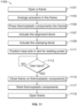
- a method for joining a plurality of thermoplastic support components to a thermoplastic component includes opening a frame to allow for the thermoplastic component and the plurality of thermoplastic support components to be positioned on a clamping block, the frame comprising at least one welding slot; actuating an alignment block to move at least one support component into alignment with the at least one welding slot; actuating a clamping block to clamp the thermoplastic component against a form block; and welding the at least one support component to the thermoplastic component through the at least one welding slot.
- thermoplastic materials to be induction welded are clamped in place, induction welding occurs, the clamp is removed, one or both of the thermoplastic materials is translated in order to align the next area to be induction welded, clamped, and so forth.
- thermoplastic welding assembly and thermoplastic welding method that enables more cost-efficient thermoplastic welding with increased stabilization for thermoplastic structures in their entirety and allow multiple coils to be used (e.g., simultaneously) to reduce the time required for the induction welding process.
- thermoplastic welding assemblies are discussed herein that allow users to weld thermoplastic components together using induction welding.
- the thermoplastic components may be made of thermoplastics, such as Polyetherketoneketone (PEKK), polyaryletherketone (PAEK), or the like; laminate; composite, and any other material suitable for induction welding.
- PEKK Polyetherketoneketone
- PAEK polyaryletherketone
- the thermoplastic components discussed herein may be made of, partially or wholly, any such materials.
- thermoplastic welding assemblies discussed herein may be used as a bench for positioning two parts to be welded by a welding induction tool and applying appropriate pressure with particular non-inductive materials during the welding process to alleviate various welding irregularities that come from conventional welding benches.
- the disclosed thermoplastic welding assemblies use a number of actuators that are used to align and clamp at least one of the thermoplastic components being welded. These actuators are made out of electrically non-conductive and non-ferrous materials. When in contact, the actuators hold the thermoplastic components in place for an induction welding probe to perform an induction weld and afterward in order for the then-welded thermoplastic components to cooldown and the weld to cure.
- FIG. 1 illustrates a perspective view of a welding configuration 100 according to various examples of the present disclosure.
- the example of the welding configuration 100 is for illustration only. Other examples may be used without departing from the scope of the claims.
- the present disclosure contemplates induction welding configurations having different shapes, sizes, configurations, etc.
- An induction welding tool 102 is mounted to a robotic arm 104 that moves the welding tool 102 into and out of a thermoplastic welding assembly 106.
- the thermoplastic welding assembly 106 includes an outer structural shell 108 to support the various parts discussed below.
- the outer structural shell 108 defines an upper cage 110 for a press and various pressurizers to hold the thermoplastic components being welded and a lower cage 112 to store various actuators for opening the press and moving the pressurizers into place.
- the outer structural shell 108 is or creates a bench, as described in greater detail below.
- the upper cage 110 is illustrated in FIG. 1 as provided in a rectangular shape, various examples are possible.
- the upper cage 110 is provided in the shape of the components to be welded.
- the outer cage 110 is provided in a triangular shape to facilitate the induction welding of the thermoplastic component 312 and the thermoplastic support component 314 in a triangular shape.
- thermoplastic welding assembly 106 Only the outer structural shell 108 of the thermoplastic welding assembly 106 is shown in welding configuration 100 for clarity. The various internal components are depicted in subsequent FIGS. 3A-10 and discussed in more detail below.
- the lower cage 112 includes a processor 118 and computer-storage memory 120.
- Software and/or firmware control instructions 122 are stored in the memory 120 and executable by the processor 118 to move the frame 302 and actuators 409, 413, described in greater detail below, based on various inputs being received at the thermoplastic welding assembly 106 or another device configured to control operation of the thermoplastic welding assembly 106. Accordingly, the control instructions 122 selectively activate the actuator 409 and the actuator 413 depending on the particular input received.
- the control instructions 122 executable code including instructions that, when executed, cause the processor 118 detect that a particular input is received or detected and consequently open the frame 302 by moving the upper portion 304 and/or the lower portion 306 away from each other.
- the control instructions 122 further include executable code including instructions that, when executed, close the frame 302 and actuate one or both of the actuator 409 and the actuator 413.
- the processor 118 may include any quantity of central processing units (CPUs), electrical controllers, microcontrollers, application-specific integrated circuits (ASICs), systems on chip (SoC), or other processing units configured to execute the control instructions 122 and/or some or all of the operations in the flow charts discussed below and depicted in the accompanying figures. Moreover, in some examples, the processors 118 represent an example of analog techniques to perform the control instructions 122 and operations described herein.
- CPUs central processing units
- ASICs application-specific integrated circuits
- SoC systems on chip
- the memory 120 may take the form of the computer-storage memory device referenced below and operatively provide storage of computer-readable instructions, data structures, program modules and other data for the thermoplastic welding assembly 106. Aside from the control instructions 122, the memory 120 stores one or more of an operating system (OS), a universal application platform, or other program modules and program data. The memory 120 is thus able to store and access data that are executable by processor 118 and configured to carry out the various operations disclosed herein. In some examples, the memory 120 stores executable computer instructions for an OS and various software applications.
- OS operating system
- the memory 120 stores executable computer instructions for an OS and various software applications.
- the OS may be any OS designed to the control the functionality of the thermoplastic welding assembly 106, including, for example but without limitation: WINDOWS ® developed by the MICROSOFT CORPORATION ® , MAC OS ® developed by APPLE, INC. ® of Cupertino, Calif., ANDROID TM developed by GOOGLE, INC. ® of Mountain View, California, open-source LINUX ® , and the like.
- WINDOWS ® developed by the MICROSOFT CORPORATION ®
- MAC OS ® developed by APPLE, INC. ® of Cupertino, Calif.
- ANDROID TM developed by GOOGLE, INC. ® of Mountain View, California, open-source LINUX ® , and the like.
- Computer-readable media comprise computer-storage memory devices and communication media.
- Computer-storage memory devices may include volatile, nonvolatile, removable, non-removable, or other memory implemented in any method or technology for storage of information such as computer-readable instructions, data structures, program modules, or the like.
- Computer-storage memory devices are tangible and mutually exclusive to communication media.
- Computer-storage memory devices are implemented in hardware and exclude carrier waves and propagated signals. Computer-storage memory devices for purposes of this disclosure are not signals per se.
- Example computer-storage memory devices include hard disks, flash drives, solid state memory, phase change random-access memory (PRAM), static random-access memory (SRAM), dynamic random-access memory (DRAM), other types of random-access memory (RAM), read-only memory (ROM), electrically erasable programmable read-only memory (EEPROM), flash memory or other memory technology, compact disk read-only memory (CD-ROM), digital versatile disks (DVD) or other optical storage, magnetic cassettes, magnetic tape, magnetic disk storage or other magnetic storage devices, or any other non-transmission medium that may be used to store information for access by a computing device.
- communication media typically embody computer readable instructions, data structures, program modules, or the like in a modulated data signal such as a carrier wave or other transport mechanism and include any information delivery media.
- the computer-executable control instructions 122 may be organized into one or more computer-executable components or modules stored in the memory 120.
- program modules include, but are not limited to, routines, programs, objects, components, and data structures that perform particular tasks or implement particular abstract data types. Examples of the present disclosure may be implemented with any number and organization of such components or modules. For example, the disclosure is not limited to the specific computer-executable instructions, components, or modules illustrated in the figures and described herein. Other examples of the disclosure may include different computer-executable instructions or components having more or less functionality than illustrated and described herein.
- examples of the disclosure transform the general-purpose computer into a special-purpose computing device, CPU, electrical controller, microcontroller, ASIC, SoC, or other processing unit for specifically controlling and operating the thermoplastic welding assembly 106.
- any suitable program code instructions may be loaded onto the memory 120 to produce a particular machine, such that the particular machine becomes a means for implementing the functions specified herein.
- These control instructions 122 when loaded into the memory 120 for execution by the processor 118, create the specific electrically controlled thermoplastic welding assembly 106 described herein.
- examples having processor 118 and the memory 120 executing and storing the control instructions 122 constitute a specific processing device that for controlling thermoplastic welding in the particular thermoplastic welding assemblies 106 described herein.
- the robotic arm 104 operates to move and insert a welding probe 114, such as an induction welding probe, of the welding tool 102 into a slot 116 defined in the upper cage 110 and throughout the press housed therein.
- the induction welding probe 114 includes an induction coil that may be selectively operated to inductively weld the thermoplastic components.
- thermoplastic components are held together in the press within the upper cage 110 using the assembly parts discussed below, and the induction welding probe 114 is inserted through the slot 116 and used to inductively weld the thermoplastic components together.
- the welding configuration 100 of FIG. 1 is only one example of a welding configuration.
- Alternative examples of welding configurations use different robotic arms 104 to control the welding tool 102, and others do not use a robotic arm 104 at all, relying instead on manual movement of the welding tool 102.
- Still other examples use a welding tool 102 that is supported by a robotic arm and also manually guided into and out of the slot 116. Numerous different configurations are fully contemplated by this disclosure.
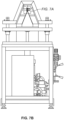
- FIG. 2 illustrates a side view of the thermoplastic welding assembly 106 for joining a first thermoplastic component to a second thermoplastic component using thermoplastic welding, according to various examples of the present disclosure.
- the thermoplastic welding assembly 106 includes the outer structural shell 108 that defines the upper cage 110.
- the upper cage 110 houses and supports a press 202 that is made up of a first portion 204 and a second portion 206.
- Movable plate brackets 208 anchor the second portion 206 to a base plate 210 and are movable along bracket tracks 212 vertically along vertical axis 214.
- the majority of examples discussed herein refer to a vertical press, or frame, 202 with the first portion 204 and the second portion 206.
- some examples discussed herein refer to a vertical press 202, where the first portion 204 is a flat, upper plate and the second portion 206 is a flat, lower plate.
- Alternative examples can use a horizontal press with parallel plates that are positioned horizontally next to each other and movable along a horizontal axis and/or the first portion 204 and/or the second portion 206 provided in a shape other than a flat plate.
- the first portion 204 can be provided in a triangular shape while the second portion 206 is provided in a flat shape.
- the first portion 204 can be provided in a flat shape and the second portion 206 can be provided in a triangular shape.
- the first portion 204 and the second portion 206 are made of a metal frame and include various non-conductive tooling inserts (discussed below).
- the non-conductive inserts may be formed of different types of non-conductive materials, such as for example but without limitation, plastics, rubbers, polyurethane, foam boards, polyurethane foam boards, woods, phenolic laminates, and the like.
- the first portion 204 and the second portion 206 may each include various modular tooling inserts comprising multiple different non-conductive inserts that fit particular contours and shapes of the thermoplastic components being welded.
- the first portion 204 may be made up of two, three, four, or more non-conductive tooling inserts that fit together to define the slot 116 for the induction welding probe 114 of the welding tool 102.
- the tooling inserts of the second portion 206 may each be made up of two, three, four, or more non-conductive plates that fit together to define specific plunger cavities for the plungers and pressurizers discussed below.
- the metallic frames of the first portion 204 and the second portion 206 are strategically positioned at distances away from the targeted welding joints of the thermoplastic components so as not to interfere with inductive welding.
- the metallic frames of one or both of the of the first portion 204 and the second portion 206 are located more than 100 millimeters (mm) away from the induction welding probe 114. Other distances are used in different alternative examples.
- the press 202 is a hydraulic press with a hydraulic actuated metallic frame.
- Alternative examples use a pneumatic, electrical, or other type of press 202.
- the press 202 may be opened to load thermoplastic components to be welded and closed to hold the thermoplastic components during and after the welding by moving the first portion 204 and/or the second portion 206 toward or away from each other along depicted vertical axis 214.
- a press actuating arm 216 in the upper cage 110 opens and closes the press 202.
- the press actuating arm 216 moves in and out of a sleeve 218 and, in some examples, is driven by one or more actuators that are contained and supported in the lower cage 112.
- a press actuator 220 which may be an electric, mechanical, hydraulic, or pneumatic motor provides the motive force for moving the press actuating arm 216 up or down along the vertical axis 214. Other examples move the press actuating arm 216 in different directions to open and close the press 202. Some examples vertically move the first portion 204 while keeping the second portion 206 stationary. Other examples vertically move the second portion 206 while keeping the first portion 204 stationary. Still other examples vertically move the both the first portion 204 and the second portion 206.
- an actuator 222 is housed and supported in the lower cage 112.
- the actuator 222 may be an electric, mechanical, hydraulic, or pneumatic motor that moves the plungers, pressurizes, and actuators discussed below and shown in FIGS. 3A-10 .
- the actuator 222 is configured to supply the force (e.g., electric, mechanical, pneumatic, hydraulic, etc.) to move the disclosed plungers referenced below.
- the actuator 222 is configured to supply mechanical force to move the actuators described herein.
- the actuator 222 is a bench actuator configured to open and close a frame, such as the frame 302 described in greater detail below.
- the bench actuator 222 is a hydraulic actuator.
- the welding tool 102 is inserted through the slot 116 to perform the thermoplastic welding, first downward through the slot 116 and then horizontally along the thermoplastic components-as indicated by the dotted arrows.
- the induction welding probe 114 is inserted through one of the welding slots 308a, 308b, 308n and then moved vertically along the thermoplastic component 312 to induction weld the thermoplastic component 312 to the thermoplastic support component 314. In some examples, as shown in FIGS.
- the induction welding probe 114 is inserted through the longitudinal welding slot 310, 801 and then moved along the longitudinal welding slot 801 to induction weld the first portion of the thermoplastic component 312a to the second portion of the thermoplastic component 312b.
- the welding tool 102 includes an induction coil 224 in the induction welding probe 114.
- the induction coil 224 is operable to perform the thermoplastic weld through induction welding, electromagnetically heating the thermoplastic material of the thermoplastic components to thereby fusing the two thermoplastic components together.
- the induction coil 224 may provide a voltage at a specified frequency, such as between 10 kHz and 1 MHz, to inductively weld the thermoplastic components together.
- the two thermoplastic components are inductively heated at a weld interface between the two components to form a single aggregate component.
- a skin may be welded to a stringer or a rib, two plastic skins may be collectively welded together to form an airplane part, automotive part, motorcycle part, or the like; a foil may be welded to a plastic container; and myriad other uses exist and are fully contemplated.
- the airplane part may be a part of wing, or the automobile part may be a leather seat.
- the thermoplastic components may be welded to collectively form an airplane part, an automotive part, a boat part, or the like.
- thermoplastic welding process has demanding, inherent requirements for a proper induction weld. These requirements include, but are not limited to, high clamping loads, a high thermal environment, non-ferrous materials, restricting interference from the tooling close to the coil, maintaining uniform pressure and temperature throughout the induction welding process, and so forth in addition to maintaining cost efficient tooling.
- Current solutions fail to provide sufficient thermal and pressure management on either side of the joint area, which can result in an imprint of the pressure bladder on the finished product, lead to limitations in the thickness of the structure due to overheating, and/or result in an increased gap on the rib not being fully welded.
- the various examples of the present disclosure addresses these deficiencies by applying consolidation force throughout a welding operation using non-conductive materials.
- the thermoplastic welding assembly utilizes materials to manage the thermal requirement generated by the thermoplastic welding operation at either side of the joint, such as a joint for multiple ribs joined to skins. Examples of such a joint included a rudder or an edge.
- the thermoplastic welding assembly is operable to be reconfigurable for various tooling components for a variety of engineering structural shapes and allows for optimized processing by stabilizing the structure and allowing for multiple simultaneous welds.
- Various examples provide a frame that includes a combination of pneumatic bladders and actuators to align and clamp a thermoplastic component to be induction welded.
- FIG. 3A illustrates a perspective view of a first side of the thermoplastic welding assembly according to various examples of the present disclosure.
- FIG. 3B illustrates a cutaway view of a second side of the thermoplastic welding assembly according to various examples of the present disclosure.
- FIG. 3C illustrates a perspective view of a first side of the thermoplastic welding assembly according to various examples of the present disclosure, in particular a different example than the first side of the thermoplastic welding assembly illustrated in FIG. 3A .
- the example of the thermoplastic welding assembly 300 is for illustration only. Other examples may be used without departing from the scope of the claims.
- the present disclosure contemplates thermoplastic welding assembly configurations having different shapes, sizes, configurations, etc.
- the thermoplastic welding assembly 300 is a hydraulic and pneumatic system that includes a frame 302 situated on a bench, such as the outer structural shell 108.
- the thermoplastic welding assembly 300 is the thermoplastic welding assembly 106.
- the frame 302 comprises an upper portion 304 and a lower portion 306 arranged such that the lower portion 306 is provided in between the outer structural shell 108 and the upper portion 304, as illustrated in FIGS. 3A-3C .
- the frame 302 is the press 202
- the upper portion 304 is the first portion 204
- the lower portion 306 is the second portion 206.
- the lower portion 306 provides a base of the frame and is provided in a rectangular or square shape.
- the upper portion 304 includes two sides, each of which are provided relative to the lower portion 306 at an angle less than ninety degrees.
- the two sides meet opposite of the lower portion 306 such that, when viewed from a side angle, the upper portion 304 and the lower portion 306 create a triangle shape.
- thermoplastic components can be provided to be induction welded.
- the upper portion 304 and the lower portion 306 are separable to enable the thermoplastic components to be situated within the frame 302 for induction welding.
- the lower portion 306 is configured to be lowered to the outer structural shell 108.
- the upper portion 304 is configured to be raised away from the outer structural shell 108.
- the lower portion 306 is configured to be lowered to the outer structural shell 108 and the upper portion 304 is configured to be raised away from the outer structural shell 108.
- the upper portion 304 and the lower portion 306 are moved by the actuator 222.
- the actuator 222 can be a bench actuator configured to close and open the frame 302 by moving the upper portion 304 and the lower portion 306 toward and away from each other, respectively. As described in greater detail below, the upper portion 304 and the lower portion 306 are separated, the thermoplastic components are situated within the frame 302, and the upper portion 304 and the lower portion 306 are brought back together for the induction welding to be performed.
- the thermoplastic components to be induction welded include a thermoplastic component 312 and a plurality of thermoplastic support components 314.
- the thermoplastic component 312 can be a skin and each thermoplastic support component 314 can be an individual rib.
- a final product of the induction welding process includes a first portion of the thermoplastic component 312a induction welded to a second portion of the thermoplastic component 312b at an angle less than 180 degrees and one or more thermoplastic support components 314 induction welded to one or both of the thermoplastic components 312.
- Each side of the upper portion 304 includes a plurality of welding slots 308a, 308b, 308n. Although illustrated in FIG. 3A as comprising three such welding slots, the example provided in FIG. 3A should not be construed as limiting. Various examples are possible.
- the upper portion 304 can include more than three welding slots 308 or fewer than three welding slots 308 without departing from the scope of the claims.
- Each of the welding slots 308 are configured to receive a welding probe, such as the induction welding probe 114, to execute an induction welding process on one or more thermoplastic components contained within the frame 302.
- each of the welding slots 308 is elongated to receive the induction welding probe 114.
- the induction welding probe 114 is inserted through the welding slot 308 to perform induction welding between the thermoplastic component 312 and the thermoplastic support component 314.
- the elongated shape of the welding slot 308 enables the induction welding probe 114 to move along the width of the thermoplastic component 312 as the induction welding process of the thermoplastic component 312 to the thermoplastic support component 314 occurs.
- thermoplastic welding assembly 300 includes a plurality of induction welding probes 114, each of the plurality of welding probes positioned within one of welding slots 308a, 308b, 308n to weld the thermoplastic support components 314 to the thermoplastic component 312 simultaneously.
- the frame 302 further includes one or more longitudinal welding slots 310.
- Each longitudinal welding slot 310 is configured to receive one or more welding probes, for example the induction welding probe 114, to enable induction welding of a first portion of the thermoplastic component 312a to a second portion of the thermoplastic component 312b.
- the one or more longitudinal welding slots 310 are provided in addition to the welding slots 308a, 308b, 308n.
- the one or more longitudinal welding slots 310 are provided on the upper portion 304 and the welding slots 308a, 308b, 308n are not included on the upper portion 304.
- the thermoplastic welding assembly 300 further includes a plurality of heat sinks, such as the heat sink 411 illustrated in FIG. 4 and described in greater detail below, positioned within the welding slot 308.
- each of the plurality of welding slots 308a, 308b, through 308n includes one or more heat sinks 411.
- Each of the one or more heat sinks 411 dissipates heat during the induction welding process between thermoplastic components.
- the welding slot 308a includes one or more heat sinks 411 to dissipate heat during the induction welding of the thermoplastic component 312 to the thermoplastic support component 314 at the location of the welding slot 308a.
- Each of the heat sinks 411 further has a width that is wider than the width of the induction welding probe 114 to further facilitate the dissipation of the heat during the induction welding.
- thermoplastic welding assembly 300 further includes one or more longitudinal welding slots 310
- the thermoplastic welding assembly 300 additionally includes one or more longitudinal heat sinks 701 positioned within the longitudinal welding slot.
- the one or more longitudinal heat sinks 701 dissipate heat during the induction welding process of the first portion of the thermoplastic component 312a to the second portion of the thermoplastic component 312b.
- Each of the one or more longitudinal heat sinks 701 further has a width that is wider than the width of the induction welding probe 114 to further facilitate the dissipation of the heat during the induction welding.
- ribs-to-skin thermoplastic component structure in its entirety. Stabilizing the entirety of the ribs-to-skin thermoplastic component structure enables multiple coils to be used in the induction welding process in order to reduce the time required to complete the induction welding process, as well as enables an individualized pressure application to counteract pressure forces through the frame 302 in order to avoid an increase in gaps between parts. By further enabling an individualized pressure application for each particular rib-to-skin application, the stability of the induction welding process is improved, resulting in a higher quality weld at each particular junction between the rib and skin.
- thermoplastic welding assembly 300 that includes the actuatable pressurizer assembly 400 enables the thermoplastic components to be reconfigured to accommodate different engineering, structural shapes and the ability to pre-fit, pressurize, and weld a skin to a rib structure, e.g., the thermoplastic component 312 to the thermoplastic support component 314.
- FIG. 4A illustrates a perspective view of an actuatable pressurizer assembly according to various examples of the present disclosure.
- FIG. 4B illustrates a cutaway view of an actuatable pressurizer assembly according to various examples of the present disclosure.
- the example of the actuatable pressurizer assembly is for illustration only. Other examples may be used without departing from the scope of the claims.
- the thermoplastic welding assembly 300 includes an actuatable pressurizer assembly 400 according to various examples of the present disclosure.
- the actuatable pressurizer assembly 400 includes a plurality of individually actuatable pressurizers 419, each of which includes an alignment actuator 401 and a clamping actuator 403.
- the alignment actuator 401 and the clamping actuator 403 are independently controlled.
- FIG. 4A illustrates an actuatable pressurizer assembly that includes a plurality of individually actuatable pressurizers 419 for a particular welding slot, i.e., the welding slot 308a
- a separate plurality of individually actuatable pressurizers 419 are provided for each individual welding slot 308a, 308b, 308n.
- each of the welding slots 308a, 308b, 308n includes a separate plurality of individually actuatable pressurizers 419.
- the welding slot 308a includes a separate plurality of individually actuatable pressurizers 419
- the welding slot 308b includes a separate plurality of individually actuatable pressurizers 419
- the welding slot 308n includes a separate plurality of individually actuatable pressurizers 419, and so forth.
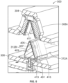
- the alignment actuator, or block, 401 is configured to move one thermoplastic support component 314 into alignment with one of the welding slots 308.
- the alignment actuator 401 moves laterally in a first direction 421 atop the lower portion 306 to position the thermoplastic support component 314 against a form block 405, which aligns the thermoplastic support component 314 with the particular welding slot 308a.
- the form block 405 includes a tool locator 407, against which the alignment actuator 401 positions the thermoplastic support component 314.
- the alignment actuator 401 moves laterally based on the actuation of an actuator 409.
- the actuator 409 is a pneumatic actuator.
- the actuator 409 can be a hydraulic actuator, an electric actuator, or any other suitable type of actuator.
- the clamping actuator, or block, 403 is configured to move the thermoplastic support component 314 into contact with the thermoplastic component 312.
- the clamping actuator 403 is actuated by an actuator 413 to clamp the thermoplastic support component 314 to the thermoplastic component 312 using the form block 405.
- the clamping actuator 403 moves vertically, i.e., away from and toward the lower portion 306 of the frame 302, in a second direction 423 based on the actuation of the actuator 413.
- the actuator 413 is a hydraulic actuator.
- the actuator 413 can be a pneumatic actuator, an electric actuator, or any other suitable type of actuator.
- the alignment actuator 401 moves laterally in a first direction 421 and the clamping actuator 403 moves vertically in a second direction 423.
- the difference between the first direction 421 and the second direction 423 is ninety degrees or approximately ninety degrees.
- the first direction 421 and the second direction 423 can differ by as little as 70 degrees or as much as 110 degrees.
- the fixed supports 415, 417 are fixed, i.e., do not move, upon the lower portion 306 of the frame 302.
- the alignment actuator 401, the clamping actuator 403, the form block 405, the tool locator 407, and the thermoplastic support component 314 are provided between the fixed support 415 and the fixed support 417.
- the fixed supports 415, 417 support the thermoplastic component 312 during the induction welding process.
- the exterior shape of the two fixed supports 415, 417 is the same or approximately the same as the interior shape of the upper portion 304 and the two fixed supports 415, 417 are the same or approximately the same shape as the alignment actuator 401, the clamping actuator 403, the form block 405, the tool locator 407, and the thermoplastic support component 314.
- the alignment actuator 401, the clamping actuator 403, and the two fixed supports 415, 417 are comprised of one or more non-ferrous, non-conductive materials so as to not interfere with the induction welding process.
- one or more of the alignment actuators 401, the clamping actuator 403, and the two fixed supports 415, 417 are comprised of a polyurethane board, a polyurethan foam, a thermoset resin/wood fiber reinforced laminate material, or any other suitable material.
- FIG. 5 illustrates a perspective, cutaway view of the thermoplastic welding assembly 300 with an open frame according to various examples of the present disclosure.
- the example of the thermoplastic welding assembly is for illustration only. Other examples may be used without departing from the scope of the claims.
- the thermoplastic welding assembly 500 can be the thermoplastic welding assembly 300 and/or the thermoplastic welding assembly 106.
- the thermoplastic welding assembly 500 includes the upper portion 304 and the lower portion 306.
- the frame 302 is in the open position, as indicated by the separation between the upper portion 304 and the lower portion 306.
- the thermoplastic component 312 has been placed on the alignment actuator 401, the clamping actuator 403, the form block 405, the fixed supports 415, 417 and the thermoplastic support component 314 in preparation for induction welding to the thermoplastic support component 314.
- the thermoplastic component 312 includes each of the first portion of the thermoplastic component 312a and the second portion of the thermoplastic component 312b placed as a single component on two sides of the alignment actuator 401, the clamping actuator 403, the form block 405, the fixed supports 415, 417 and the thermoplastic support component 314.
- the first portion of the thermoplastic component 312a and the second portion of the thermoplastic component 312b are separately placed on different sides of the alignment actuator 401, the clamping actuator 403, the form block 405, the fixed supports 415, 417 and the thermoplastic support component 314 and are later joined together, such as via induction welding.
- the thermoplastic welding assembly 500 further includes a plurality of heat sinks 411 placed on an interior of the upper portion 304. As illustrated in FIG. 5 , the plurality of heat sinks 411 are aligned at the same or approximately the same angle created by the thermoplastic component 312 on the lower portion 306. This alignment enables the plurality of heat sinks 411 to be utilized for induction welding of various points of the thermoplastic component 312 to the various points of the thermoplastic support component 314.
- FIG. 6 illustrates a perspective, cutaway view of the thermoplastic welding assembly 600 with a closed frame according to various examples of the present disclosure.
- the example of the thermoplastic welding assembly is for illustration only. Other examples may be used without departing from the scope of the claims.
- the thermoplastic welding assembly 600 illustrated in FIG. 6 , can be the thermoplastic welding assembly 300, the thermoplastic welding assembly 106, and/or the thermoplastic welding assembly 500.
- the thermoplastic welding assembly 600 illustrates the thermoplastic welding assembly 500, but with the frame 302 in the closed position rather than the open position illustrated in FIG. 5 .
- the thermoplastic welding assembly 600 includes the upper portion 304 in closer proximity to the lower portion 306 than as illustrated in the open position as in FIG. 5 .
- thermoplastic component 312 is provided on the lower portion 306 at the same or approximately the same angle as the interior of the upper portion 304.
- the complementary angles of the interior of the upper portion 304 and the thermoplastic component 312 enable the frame 302 to be closed in a manner that enables the thermoplastic component 312 to be pressed to the thermoplastic support component 314 for induction welding.
- FIG. 7A illustrates a side, cutaway view of the thermoplastic welding assembly according to various examples of the present disclosure.
- FIG. 7B illustrates a side view of the thermoplastic welding assembly according to various examples of the present disclosure.
- the example of the thermoplastic welding assembly is for illustration only. Other examples may be used without departing from the scope of the claims.
- FIGS. 7A and 7B illustrate an example where a single tool can be utilized to perform induction welding both between the thermoplastic component 312 and one or more thermoplastic support components 314 and between the first portion of the thermoplastic component 312a and the second portion of the thermoplastic component 312b.
- the example illustrated in FIGS. 7A and 7B provides thermoplastic skin closing out and rib joining in a single tool.
- the thermoplastic welding assembly 500 includes the upper portion 304 and lower portion 306 of the frame 302.
- the thermoplastic welding assembly 700 is the thermoplastic welding assembly 300 and/or the thermoplastic welding assembly 106.
- the side, cutaway view illustrated in FIG. 7A particularly illustrates the junction of the first portion of the thermoplastic component 312a and the second portion of the thermoplastic component 312b.
- the side, cutaway view illustrated in FIG. 7A further illustrates the fixed support 417 and the thermoplastic component 312 atop the fixed support 417.
- Between the thermoplastic component 312 and the upper portion 304 is a plurality of non-conductive support pieces 705, 707, 709.
- the plurality of non-conductive support pieces 705, 707, 709 are comprised of a polyurethane board, a polyurethan foam, a thermoset resin/wood fiber reinforced laminate material, or any other suitable material.
- the frame 302 is vacuum sealed to hold the skin, i.e., the thermoplastic component 312, on the fixed supports 415,417.
- the thermoplastic welding assembly 700 further includes a longitudinal heat sink 701 disposed adjacent to the first portion of the thermoplastic component 312a.
- the longitudinal heat sink 701 is a ceramic insert and provided within the longitudinal welding slot 715, described in greater detail below.
- a ceramic holder 703 is provided adjacent to the longitudinal heat sink 701 such that the longitudinal heat sink 701 is disposed between the ceramic holder 703 and the first portion of the thermoplastic component 312a.
- the longitudinal heat sink 701 is provided as a portion of the ceramic holder 703.
- the longitudinal heat sink 701 is surrounded on three sides by the ceramic holder 703 such that the ceramic holder 703 provides structural support to the longitudinal heat sink 701.
- a polymer support piece 717 is provided adjacent to the second portion of the thermoplastic component 312b.
- the polymer support piece 717 provides high temperature resistance up to a range of between 250°C (480°F) and 500°C (1022°F), i.e., the temperature ranges required for induction welding of thermoplastic materials, and structural support throughout the induction welding process.
- a non-conductive support piece 711 is additionally provided adjacent to the polymer support piece 717.
- the non-conductive support piece 711 is comprised of a polyurethane board, a polyurethan foam, a thermoset resin/wood fiber reinforced laminate material, or any other suitable material.
- the non-conductive support piece 711 is supported by a bladder 713 that can inflate to provide support to the non-conductive support piece 711 during the induction welding process, and with the polymer support piece 717 provides support to the thermoplastic component 312 during the induction welding process.
- the polymer support piece 717 and the non-conductive support piece 711 are provided between the second portion of the thermoplastic component 312b and the bladder 713.
- the bladder 713 is a fire hose bladder.
- the bladder 713 can be any type of bladder sufficient to provide support to the non-conductive support piece 711, the polymer support piece 717, and the thermoplastic component 312 during the induction welding process.
- the non-conductive support pieces 705 and 707 are provided such that a space is present between the non-conductive support pieces 705 and 707.
- the space between the non-conductive support pieces 705 and 707 defines a longitudinal welding slot 715 configured to receive a welding probe, such as the induction welding probe 114.
- the longitudinal welding slot 715 is the longitudinal welding slot 310.
- the longitudinal heat sink 701, ceramic holder 703, polymer support piece 717, non-conductive support piece 711, and the bladder 713 are provided longitudinally with the longitudinal welding slot 715 and the junction of the first portion of the thermoplastic component 312a and the second portion of the thermoplastic component 312b such that the induction welding probe 114 performs induction welding of the first portion of the thermoplastic component 312a and the second portion of the thermoplastic component 312b through the longitudinal welding slot 715.
- the longitudinal welding slot 715 is provided in the same location on the upper portion 304 as the one or more welding slots 308a, 308b, 308n.
- the induction welding probe 114 is configured to perform induction welding of the thermoplastic component 312 to the thermoplastic support component 314 through the welding slot 308n and induction welding of the first portion of the thermoplastic component 312a and the second portion of the thermoplastic component 312b through the longitudinal welding slot 715 at the location of the welding slot 308n.
- FIG. 8 illustrates a perspective view of an example of the thermoplastic welding assembly according to various examples of the present disclosure.
- FIG. 9A illustrates a cutaway, perspective view of an example of the thermoplastic welding assembly and
- FIG. 9B illustrates a magnified cutaway, perspective view of an example of the thermoplastic welding assembly according to various examples of the present disclosure according to various examples of the present disclosure.
- the example thermoplastic welding assembly is for illustration only. Other examples may be used without departing from the scope of the claims.
- the thermoplastic welding assembly 800 is placed on the outer structural shell 108 and includes a longitudinal welding slot 801.
- the longitudinal welding slot 801 is the longitudinal welding slot 310 and/or the longitudinal welding slot 715.
- the longitudinal welding slot 801 is provided in a substantially horizontal direction and accordingly can be referred to herein as a horizontal welding slot.
- the longitudinal welding slot 801 is configured to receive the induction welding probe 114 for joining a first portion of the thermoplastic component 312a to a second portion of the thermoplastic component 312b.
- the longitudinal welding slot 801 corresponds to the longitudinal welding slot 715 defined by the space between the non-conductive support pieces 705 and 707.
- the longitudinal welding slot 801 is provided as the only welding slot on the upper portion 304 of the frame 302. In other words, the longitudinal welding slot 801 is provided while the welding slots 308a, 308b, 308n are not provided. In other examples, as shown in FIG. 3C , one or more of the welding slots 308a, 308b, 308n are provided on the upper portion 304 while the longitudinal welding slot 801 is not provided as a separate welding slot on the upper portion 304, but is provided as overlapping with the one or more welding slots 308a, 308b, 308n.
- each of the one or more welding slots 308a, 308b, 308n and the longitudinal welding slot 801 are each separately provided on the upper portion 304.
- the one or more welding slots 308a, 308b, 308n are provided in a substantially vertical direction and the longitudinal welding slot 801 is provided in a substantially horizontal direction.
- thermoplastic welding assembly 800 further includes the non-conductive support pieces 705, 707, 709 and the bladder 713. As illustrated in FIGS. 9A and 9B , the thermoplastic welding assembly 800 further includes the longitudinal heat sink 701, the ceramic holder 703, the non-conductive support piece 711, and the polymer support piece 717. The ceramic holder 703 is placed proximate to the longitudinal welding slot 801 such that the induction welding probe 114 can be inserted through the longitudinal welding slot 801 and perform induction welding on the first portion of the thermoplastic component 312a and the second portion of the thermoplastic component 312b.
- FIG. 10 illustrates a cutaway view of an interior of the thermoplastic welding assembly according to various examples of the present disclosure.
- the example thermoplastic welding assembly is for illustration only. Other examples may be used without departing from the scope of the claims.
- FIG. 10 illustrates a support portion placed on the interior of the upper portion 304.
- the thermoplastic welding assembly 1000 illustrated in FIG. 10 can be one or more of the thermoplastic welding assembly 106, the thermoplastic welding assembly 300, the thermoplastic welding assembly 500, the thermoplastic welding assembly 600, the thermoplastic welding assembly 700, and/or the thermoplastic welding assembly 800.
- the thermoplastic welding assembly 1000 includes a ceramic insert 1001.
- the ceramic insert 1001 can be a heat sink, such as the heat sink 411 and/or the longitudinal heat sink 701.
- the ceramic insert 1001 is supported by a ceramic insert carrier 1003, such as the ceramic holder 703.
- the ceramic insert 1001 is surrounded on three sides by the ceramic insert carrier 1003 to provide structural support to the ceramic insert 1001.
- the frame 302 is closed, the ceramic insert 1001 is held in place by the ceramic insert carrier 1003 on three sides and the thermoplastic component 312 on a fourth side.
- the thermoplastic welding assembly 1000 further includes support pieces such as the support piece 1005 and the support piece 1007.
- the support pieces 1005, 1007 are provided on the interior of the upper portion 304 and prevent unnecessary movement of the ceramic insert 1001 and the ceramic insert carrier 1003.
- the support pieces 1005, 1007 are comprised of a polyurethane board, a polyurethan foam, a thermoset resin/wood fiber reinforced laminate material, or any other suitable material.
- FIG. 11 illustrates a flowchart diagram illustrating an operational workflow method for welding thermoplastic components welding thermoplastic according to various examples of the present disclosure.
- the method 1100 can be executed by one or more components described herein, such as the thermoplastic welding assembly 106, 300.
- the method 1100 may be implemented by the thermoplastic welding assembly 300 equipped with the previously discussed frame 302 that includes the upper portion 304 with the welding slots 308a, 308b, 308n for the induction welding probe 114 and the lower portion 306.
- Various examples of the method 1100 may be performed without departing from the scope of the claims.
- the frame 302 is opened by separating the upper portion 304 and the lower portion 306 in step 1101.
- the actuators such as the alignment actuator 401 and the clamping actuator 403, are arranged in the frame 302.
- thermoplastic components such as the thermoplastic component 312 and the thermoplastic support component 314, are pressed into the frame 302.
- step 1107 the alignment actuator, or block, 401 is actuated to move the thermoplastic support component 314 into alignment with at least one welding slot 308.
- step 1109 the clamping actuator, or block, 403 is actuated to clamp the thermoplastic component 312 against the form block 405.
- step 1111 one or more heat sinks 411 is placed in the at least one welding slot 308.
- the induction welding probe 114 is then placed proximate to the one or more heat sinks 411 placed in the at least one welding slot 308.
- step 1113 it is determined whether a user input is received.
- the thermoplastic welding assembly 300 receives a user input to initiate the induction welding.
- the method 1100 returns to step 1113 and again determines whether the user input is received.
- the frame 302 is closed on the thermoplastic components 312 and thermoplastic support components 314.
- the welding is initiated and performed by the welding tool 102, for example the induction welding probe 114.
- multiple thermoplastic support components 314 are induction welded to the thermoplastic component 312 simultaneously.
- step 1119 following completion of the induction welding process, the frame 302 is opened and the welded thermoplastic components are removed.
- step 1103 can be omitted and the method 1100 proceeds to pressing the thermoplastic components into the frame 302 in step 1105.
- FIG. 12 illustrates a schematic perspective view of an aircraft having one or more portions assembled by the thermoplastic welding systems and methods according to various examples of the present disclosure.
- One or more examples allow for fabrication of thermoplastic aircraft parts for an aircraft 1200 as illustrated in FIG. 12 .
- the aircraft 1200 includes a wing 1202 and a wing 1204 attached to a body 1206.
- the aircraft 1200 also includes an engine 1208 attached to the wing 1202 and an engine 1210 attached to the wing 1204.
- the body 1206 has a tail section 1212 with a horizontal stabilizer 1214, a horizontal stabilizer 1216, and a vertical stabilizer 1218 attached to the tail section 1212 of the body 1206.
- the body 1206 in some examples has a composite skin 1220.
- the aircraft 1200 is an example of an aircraft in which welded thermoplastic structures can be implemented in accordance with various examples described herein.
- a composite bracket and blade stringer of the aircraft 1200 is a welded thermoplastic structure formed according to the present disclosure.
- a structural support such as a spar, rib, or other structural support of the wing 1202, the wing 1204, or the body 1206 welded to another component comprises a thermoplastic structure.
- a structural support of the body 1206 welded to the composite skin 1220 can comprise a welded thermoplastic structure.
- the present disclosure allows induction welding of different geometries or configurations of parts with magnetic flux from the induction coil 224 applied to only one side of the thermoplastic components to be welded.
- the induction coil 224 allows for induction welding from one side while effectively spreading heat and pressure as described herein.
- some or all examples of the present disclosure can be implemented at least on the wing 1204, the body 1206, and/or the composite skin 1220 described herein.
- the illustration of the aircraft 1200 is not meant to imply physical or architectural limitations to the manner in which an illustrative configuration may be implemented.
- the aircraft 1200 is a commercial aircraft, the aircraft 1200 can be a military aircraft, a rotorcraft, a helicopter, an unmanned aerial vehicle, or any other suitable aircraft.
- Other vehicles are possible as well, such as, for example but without limitation, an automobile, a motorcycle, a bus, a boat, a train, or the like.
- various examples facilitate induction welding of parts by improving the heating of (e.g., more uniformly heat) the weld interface between the parts from a single side of the parts.
- the present disclosure can be implemented using different manufacturing environments. For example, some or all examples of the present disclosure can be implemented at least in the material procurement and component and assembly manufacturing, as described herein.
- thermoplastic welding assembly including a plurality of welding slot, a plurality of heat sinks, a plurality of individually actuatable pressurizers, a plurality of induction welding probes, and a longitudinal welding slot
- thermoplastic welding assembly including a plurality of welding slot, a plurality of heat sinks, a plurality of individually actuatable pressurizers, a plurality of induction welding probes, and a longitudinal welding slot
- these examples are provided for illustration only and should not be construed as limiting.
- some examples can include one or more of a single welding slot, a single heat sink, a single actuatable pressurizer assembly, a single induction welding probe, a plurality of longitudinal welding slots, and so forth.
- a thermoplastic welding assembly (106, 300, 500, 600, 700, 800, 1000) for joining a plurality of thermoplastic support components (314) to a thermoplastic component (312), comprises: a frame (302) having a plurality of welding slots (308a, 308b, 308n); a plurality of heat sinks (411), each heat sink (411) positioned within one of the welding slots (308a, 308b, 308n); and a plurality of individually actuatable pressurizers (400), each pressurizer (400) comprises: an alignment actuator (401) configured to move one thermoplastic support component (314) into alignment with one welding slot (308), and a clamping actuator (403) configured to move the one thermoplastic support component (314) into contact with the thermoplastic component (312).
- thermoplastic welding assembly (106, 300, 500, 600, 700, 800, 1000) of the preceding paragraph further comprises a form block (405) against which the clamping actuator (403) presses the one thermoplastic support component (314) and the thermoplastic component (312) together.
- the form block (405) further comprises a tool locator (407), wherein the alignment actuator (401) is configured to position the one thermoplastic support component (314) against the tool locator (407).
- the frame (302) further comprises a longitudinal welding slot (715, 801) configured to receive a welding probe (114) for joining a first portion (312a) of the thermoplastic component to a second portion (312b) of the thermoplastic component.
- thermoplastic welding assembly (106, 300, 500, 600, 700, 800, 1000) of any of the preceding four paragraphs further comprises a longitudinal heat sink positioned within the longitudinal welding slot (715, 801) to dissipate heat during welding of the first portion of the thermoplastic component to the second portion of the thermoplastic component.
- the heat sink has a width wider than the welding probe.
- the frame (302) comprises: an upper portion (304) having the plurality of welding slots (308a, 308b, 308n), and a lower portion (306) supporting the alignment actuator (401) and the clamping actuator (403).
- thermoplastic welding assembly (106, 300, 500, 600, 700, 800, 1000) of any of the preceding seven paragraphs further comprises a bench actuator (222) configured to close and open the frame (302) by moving the upper portion (304) and the lower portion (306) toward and away from each other, respectively.
- the bench actuator (222) is a hydraulic actuator.
- the clamping actuator (403) is a pneumatic actuator.
- the one thermoplastic support component (314) is a rib.
- thermoplastic component (312) is a skin.
- thermoplastic welding assembly (106, 300, 500, 600, 700, 800, 1000) of any of the preceding twelve paragraphs further comprises a welding probe (114) for welding the plurality of thermoplastic support components (314) to the thermoplastic component (312) through the welding slots (308a, 308b, 308n).
- the welding probe (114) is an induction welding probe.
- thermoplastic component 312
- thermoplastic support components 314
- thermoplastic welding assembly 106, 300, 500, 600, 700, 800, 1000
- thermoplastic welding assembly (106, 300, 500, 600, 700, 800, 1000) for joining a plurality of thermoplastic support components (314) to a thermoplastic component (312), comprises: a frame (302) having a plurality of welding slots (308a, 308b, 308n); a plurality of individually actuatable pressurizers (400), each pressurizer comprises: an alignment block (401) movable in a first direction to move one thermoplastic support component (314) into alignment with one welding slot (308n), and a clamping block (403) movable in a second direction to move the one thermoplastic support component (314) into contact with the thermoplastic component (312), wherein the first direction is a different direction than the second direction; and a plurality of actuators (409, 413) configured to move the alignment block (401) and the clamping block (403).
- the first direction and the second direction differ by between 70-110 degrees from each other.
- thermoplastic welding assembly (106, 300, 500, 600, 700, 800, 1000) of either of the preceding two paragraphs further comprises a plurality of heat sinks (411), each heat sink positioned within one of the welding slots.
- thermoplastic welding assembly (106, 300, 500, 600, 700, 800, 1000) of any of the preceding three paragraphs further comprises a plurality of welding probes (114) positioned within the plurality of welding slots to weld the thermoplastic support components (314) to the thermoplastic component (312) at the same time.
- the clamping block (403) and the alignment block (401) are made of non-conductive material.
- thermoplastic component 312
- thermoplastic support components 314
- thermoplastic welding assembly 106, 300, 500, 600, 700, 800, 1000
- a method (1100) for joining a plurality of thermoplastic support components to a thermoplastic component comprises: opening (1101) a frame to allow for the thermoplastic component and the plurality of thermoplastic support components to be positioned on a clamping block (403), the frame comprising at least one welding slot; actuating (1107) an alignment block (401) to move at least one support component into alignment with the at least one welding slot; actuating (1109) a clamping block (403) to clamp the thermoplastic component against a form block; and welding (1117) the at least one support component to the thermoplastic component through the at least one welding slot.
- the operations illustrated in the figures may be implemented as software instructions encoded on a computer readable medium, in hardware programmed or designed to perform the operations, or both.
- the disclosed concept may be implemented as an ASIC, SoC, or other circuitry including a plurality of interconnected, electrically conductive elements.
Landscapes
- Engineering & Computer Science (AREA)
- Mechanical Engineering (AREA)
- Physics & Mathematics (AREA)
- Thermal Sciences (AREA)
- Fluid Mechanics (AREA)
- Robotics (AREA)
- Lining Or Joining Of Plastics Or The Like (AREA)
Abstract
Description
- Thermoplastic materials like polyethylene, polyvinyl chloride, nylons, polypropylene, acetals, and the like have become increasingly important as materials of products and machinery because of their moldability, ease of handling, light weight, and ability to withstand corrosion. Often, different thermoplastic materials are joined together for various applications, such as to make aerospace, automotive, mining, or other parts. Numerous techniques have been developed for the joining of thermoplastic materials, including welding and the use of adhesives. Thermoplastic welding is a type of welding for joining pieces of thermoplastic material using heating, pressure and cooling. To begin a thermoplastic weld, the surface of the thermoplastic material is heated to its melting point, or thermoplastic state. Each material has its own thermoplastic state, which usually ranges between 250°C (480°F) and 500°C (1022°F). The material is then pressed together until it cools. The pressure applied allows molecules in the material to newly position themselves, or to bond with molecules of another part.
- Induction welding is one particular type of thermoplastic welding that uses electromagnetic induction to heat components without contacting the components. An induction welding probe emits an inductive field toward two thermoplastic components to be joined, which induces heat in the components and allows them to weld together. Neither component is contacted by the induction coil itself, as only the electromagnetic field is necessary to induce the heat in the components. Induction welding requires that the components remain in contact with each other to induce heating, meld together, and then cool properly to form a strong thermoplastic weld. Conventional benches and presses used for thermoplastic welding may apply an incorrect pressure to the side of the components opposite the welding probe, which frequently results in welding issues like squeeze out or delamination issues. Or, if some sort of bladder is used to push the components together during welding, bladder imprints are often found where the bladder rubbed off, or imprinted, on one of the components. Accordingly, conventional welding benches do not provide mechanisms for holding thermoplastic components together with the correct pressure from various angles or by materials that do not imprint during welding. There is, therefore, a desire for an improved thermoplastic welding assembly and thermoplastic welding method.
- The disclosed examples are described in detail below with reference to the accompanying drawing figures listed below. The following summary is provided to illustrate examples disclosed herein. It is not meant, however, to limit all examples to any particular configuration or sequence of operations.
- A thermoplastic welding assembly is provided for welding thermoplastic components. The thermoplastic welding assembly includes a frame, a plurality of heat sinks, and a plurality of individually actuatable pressurizers. The frame includes a plurality of welding slots. Each heat sink of the plurality of heat sinks is positioned within one of the welding slots. Each pressurizer of the plurality of individually actuatable pressurizers includes an alignment actuator configured to move one thermoplastic support component into alignment with one welding slot, and a clamping actuator configured to move the one thermoplastic support component into contact with the thermoplastic component.
- A thermoplastic welding assembly is provided for welding thermoplastic components. The thermoplastic welding assembly includes a frame, a plurality of individually actuatable pressurizers, and a plurality of actuators. The frame includes a plurality of welding slots. Each pressurizer of the plurality of individually actuatable pressurizers includes an alignment block movable in a first direction to move one thermoplastic support component into alignment with one welding slot, and a clamping block movable in a second direction to move the one thermoplastic support component into contact with the thermoplastic component, wherein the first direction is a different direction than the second direction. The plurality of actuators is configured to move the alignment block and the clamping block.
- A method is provided for joining a plurality of thermoplastic support components to a thermoplastic component. The method includes opening a frame to allow for the thermoplastic component and the plurality of thermoplastic support components to be positioned on a clamping block, the frame comprising at least one welding slot; actuating an alignment block to move at least one support component into alignment with the at least one welding slot; actuating a clamping block to clamp the thermoplastic component against a form block; and welding the at least one support component to the thermoplastic component through the at least one welding slot.
- Other technical features may be readily apparent to one skilled in the art from the following figures, descriptions, and claims.
- For a more complete understanding of the present disclosure and its advantages, reference is now made to the following description taken in conjunction with the accompanying drawings, in which like reference numerals represent like parts:
-
FIG. 1 illustrates a perspective view of a welding configuration; -
FIG. 2 illustrates a side view of a thermoplastic welding assembly; -
FIG. 3A illustrates a perspective view of a first side of the thermoplastic welding assembly; -
FIG. 3B illustrates a cutaway view of a second side of the thermoplastic welding assembly; -
FIG. 3C illustrates a perspective view of a first side of the thermoplastic welding assembly; -
FIG. 4A illustrates a perspective view of an actuatable pressurizer assembly; -
FIG. 4B illustrates a cutaway view of the actuatable pressurizer assembly; -
FIG. 5 illustrates a perspective, cutaway view of the thermoplastic welding assembly with an open frame; -
FIG. 6 illustrates a perspective, cutaway view of the thermoplastic welding assembly with a closed frame; -
FIG. 7A illustrates a side, cutaway view of the thermoplastic welding assembly; -
FIG. 7B illustrates a side view of the thermoplastic welding assembly; -
FIG. 8 illustrates a perspective view of an example of the thermoplastic welding assembly; -
FIG. 9A illustrates a cutaway, perspective view of an example of the thermoplastic welding assembly; -
FIG. 9B illustrates a magnified cutaway, perspective view of an example of the thermoplastic welding assembly; -
FIG. 10 illustrates a cutaway view of an interior of the thermoplastic welding assembly; -
FIG. 11 illustrates a flowchart diagram illustrating a workflow for welding thermoplastic components welding thermoplastic; and -
FIG. 12 illustrates a schematic perspective view of an aircraft having one or more portions assembled by the thermoplastic welding systems and methods. - Corresponding reference characters indicate corresponding parts throughout the accompanying drawings.
- The various examples will be described in detail with reference to the accompanying drawings. Wherever possible, the same reference numbers will be used throughout the drawings to refer to the same or like parts. References made throughout this disclosure relating to specific examples are provided solely for illustrative purposes but, unless indicated to the contrary, are not meant to limit all examples.
- The foregoing summary, as well as the following detailed description of certain examples will be better understood when read in conjunction with the appended drawings. As used herein, an element or step recited in the singular and preceded by the word "a" or "an" should be understood as not necessarily excluding the plural of the elements or steps. Further, references to an example are not intended to be interpreted as excluding the existence of additional examples that also incorporate the recited features. Moreover, unless explicitly stated to the contrary, examples "comprising" or "having" an element or a plurality of elements having a particular property could include additional elements not having that property.
- As noted above, conventional benches and presses used for thermoplastic welding may risk applying an incorrect pressure to the side of the components opposite the welding probe, which can result in welding issues like squeeze out or delamination issues. Other conventional benches and presses, even if pressure is applied correctly, may require significant human costs to manually arrange both the structures to be induction welded as well as support structures used to help facilitate the induction welding. These solutions are time consuming, expensive, and prone to less than optimal issues like squeeze out or delamination issues.
- In particular, conventional methods of induction welding to address these challenges generally require each weld to be executed individually on a press. In other words, the thermoplastic materials to be induction welded are clamped in place, induction welding occurs, the clamp is removed, one or both of the thermoplastic materials is translated in order to align the next area to be induction welded, clamped, and so forth. There is, therefore, a desire for an improved thermoplastic welding assembly and thermoplastic welding method that enables more cost-efficient thermoplastic welding with increased stabilization for thermoplastic structures in their entirety and allow multiple coils to be used (e.g., simultaneously) to reduce the time required for the induction welding process.
- Various thermoplastic welding assemblies are discussed herein that allow users to weld thermoplastic components together using induction welding. The thermoplastic components may be made of thermoplastics, such as Polyetherketoneketone (PEKK), polyaryletherketone (PAEK), or the like; laminate; composite, and any other material suitable for induction welding. The thermoplastic components discussed herein may be made of, partially or wholly, any such materials.
- The thermoplastic welding assemblies discussed herein may be used as a bench for positioning two parts to be welded by a welding induction tool and applying appropriate pressure with particular non-inductive materials during the welding process to alleviate various welding irregularities that come from conventional welding benches. In particular, the disclosed thermoplastic welding assemblies use a number of actuators that are used to align and clamp at least one of the thermoplastic components being welded. These actuators are made out of electrically non-conductive and non-ferrous materials. When in contact, the actuators hold the thermoplastic components in place for an induction welding probe to perform an induction weld and afterward in order for the then-welded thermoplastic components to cooldown and the weld to cure.
-
FIG. 1 illustrates a perspective view of awelding configuration 100 according to various examples of the present disclosure. The example of thewelding configuration 100 is for illustration only. Other examples may be used without departing from the scope of the claims. For example, the present disclosure contemplates induction welding configurations having different shapes, sizes, configurations, etc. - An
induction welding tool 102 is mounted to arobotic arm 104 that moves thewelding tool 102 into and out of athermoplastic welding assembly 106. Thethermoplastic welding assembly 106 includes an outerstructural shell 108 to support the various parts discussed below. The outerstructural shell 108 defines anupper cage 110 for a press and various pressurizers to hold the thermoplastic components being welded and alower cage 112 to store various actuators for opening the press and moving the pressurizers into place. In some examples, the outerstructural shell 108 is or creates a bench, as described in greater detail below. - It should be understood that although the
upper cage 110 is illustrated inFIG. 1 as provided in a rectangular shape, various examples are possible. Theupper cage 110 is provided in the shape of the components to be welded. For example, when welding thethermoplastic component 312 and thethermoplastic support component 314 illustrated inFIGS. 3A-10 below, theouter cage 110 is provided in a triangular shape to facilitate the induction welding of thethermoplastic component 312 and thethermoplastic support component 314 in a triangular shape. - Only the outer
structural shell 108 of thethermoplastic welding assembly 106 is shown inwelding configuration 100 for clarity. The various internal components are depicted in subsequentFIGS. 3A-10 and discussed in more detail below. - In some examples, the
lower cage 112 includes aprocessor 118 and computer-storage memory 120. Software and/orfirmware control instructions 122 are stored in thememory 120 and executable by theprocessor 118 to move theframe 302 andactuators thermoplastic welding assembly 106 or another device configured to control operation of thethermoplastic welding assembly 106. Accordingly, thecontrol instructions 122 selectively activate theactuator 409 and theactuator 413 depending on the particular input received. For instance, thecontrol instructions 122 executable code including instructions that, when executed, cause theprocessor 118 detect that a particular input is received or detected and consequently open theframe 302 by moving theupper portion 304 and/or thelower portion 306 away from each other. Thecontrol instructions 122 further include executable code including instructions that, when executed, close theframe 302 and actuate one or both of theactuator 409 and theactuator 413. - The
processor 118 may include any quantity of central processing units (CPUs), electrical controllers, microcontrollers, application-specific integrated circuits (ASICs), systems on chip (SoC), or other processing units configured to execute thecontrol instructions 122 and/or some or all of the operations in the flow charts discussed below and depicted in the accompanying figures. Moreover, in some examples, theprocessors 118 represent an example of analog techniques to perform thecontrol instructions 122 and operations described herein. - The
memory 120 may take the form of the computer-storage memory device referenced below and operatively provide storage of computer-readable instructions, data structures, program modules and other data for thethermoplastic welding assembly 106. Aside from thecontrol instructions 122, thememory 120 stores one or more of an operating system (OS), a universal application platform, or other program modules and program data. Thememory 120 is thus able to store and access data that are executable byprocessor 118 and configured to carry out the various operations disclosed herein. In some examples, thememory 120 stores executable computer instructions for an OS and various software applications. The OS may be any OS designed to the control the functionality of thethermoplastic welding assembly 106, including, for example but without limitation: WINDOWS® developed by the MICROSOFT CORPORATION®, MAC OS® developed by APPLE, INC.® of Cupertino, Calif., ANDROID™ developed by GOOGLE, INC.® of Mountain View, California, open-source LINUX®, and the like. - By way of example and not limitation, computer-readable media, as referenced herein, comprise computer-storage memory devices and communication media. Computer-storage memory devices may include volatile, nonvolatile, removable, non-removable, or other memory implemented in any method or technology for storage of information such as computer-readable instructions, data structures, program modules, or the like. Computer-storage memory devices are tangible and mutually exclusive to communication media. Computer-storage memory devices are implemented in hardware and exclude carrier waves and propagated signals. Computer-storage memory devices for purposes of this disclosure are not signals per se. Example computer-storage memory devices include hard disks, flash drives, solid state memory, phase change random-access memory (PRAM), static random-access memory (SRAM), dynamic random-access memory (DRAM), other types of random-access memory (RAM), read-only memory (ROM), electrically erasable programmable read-only memory (EEPROM), flash memory or other memory technology, compact disk read-only memory (CD-ROM), digital versatile disks (DVD) or other optical storage, magnetic cassettes, magnetic tape, magnetic disk storage or other magnetic storage devices, or any other non-transmission medium that may be used to store information for access by a computing device. In contrast, communication media typically embody computer readable instructions, data structures, program modules, or the like in a modulated data signal such as a carrier wave or other transport mechanism and include any information delivery media.
- The computer-
executable control instructions 122 may be organized into one or more computer-executable components or modules stored in thememory 120. Generally, program modules include, but are not limited to, routines, programs, objects, components, and data structures that perform particular tasks or implement particular abstract data types. Examples of the present disclosure may be implemented with any number and organization of such components or modules. For example, the disclosure is not limited to the specific computer-executable instructions, components, or modules illustrated in the figures and described herein. Other examples of the disclosure may include different computer-executable instructions or components having more or less functionality than illustrated and described herein. In examples involving a general-purpose computer, examples of the disclosure transform the general-purpose computer into a special-purpose computing device, CPU, electrical controller, microcontroller, ASIC, SoC, or other processing unit for specifically controlling and operating thethermoplastic welding assembly 106. - As will be appreciated, any suitable program code instructions may be loaded onto the
memory 120 to produce a particular machine, such that the particular machine becomes a means for implementing the functions specified herein. Thesecontrol instructions 122, when loaded into thememory 120 for execution by theprocessor 118, create the specific electrically controlledthermoplastic welding assembly 106 described herein. In other words,examples having processor 118 and thememory 120 executing and storing thecontrol instructions 122 constitute a specific processing device that for controlling thermoplastic welding in the particularthermoplastic welding assemblies 106 described herein. - The
robotic arm 104 operates to move and insert awelding probe 114, such as an induction welding probe, of thewelding tool 102 into aslot 116 defined in theupper cage 110 and throughout the press housed therein. In some examples, theinduction welding probe 114 includes an induction coil that may be selectively operated to inductively weld the thermoplastic components. In operation of such examples, thermoplastic components are held together in the press within theupper cage 110 using the assembly parts discussed below, and theinduction welding probe 114 is inserted through theslot 116 and used to inductively weld the thermoplastic components together. - It should be understood that the
welding configuration 100 ofFIG. 1 is only one example of a welding configuration. Alternative examples of welding configurations use differentrobotic arms 104 to control thewelding tool 102, and others do not use arobotic arm 104 at all, relying instead on manual movement of thewelding tool 102. Still other examples use awelding tool 102 that is supported by a robotic arm and also manually guided into and out of theslot 116. Numerous different configurations are fully contemplated by this disclosure. -
FIG. 2 illustrates a side view of thethermoplastic welding assembly 106 for joining a first thermoplastic component to a second thermoplastic component using thermoplastic welding, according to various examples of the present disclosure. Thethermoplastic welding assembly 106 includes the outerstructural shell 108 that defines theupper cage 110. Theupper cage 110 houses and supports apress 202 that is made up of afirst portion 204 and asecond portion 206.Movable plate brackets 208 anchor thesecond portion 206 to abase plate 210 and are movable along bracket tracks 212 vertically alongvertical axis 214. - For clarity, the majority of examples discussed herein refer to a vertical press, or frame, 202 with the
first portion 204 and thesecond portion 206. For clarity, some examples discussed herein refer to avertical press 202, where thefirst portion 204 is a flat, upper plate and thesecond portion 206 is a flat, lower plate. Alternative examples can use a horizontal press with parallel plates that are positioned horizontally next to each other and movable along a horizontal axis and/or thefirst portion 204 and/or thesecond portion 206 provided in a shape other than a flat plate. For example, as illustrated inFIGS. 3A-10 below, thefirst portion 204 can be provided in a triangular shape while thesecond portion 206 is provided in a flat shape. In other examples, thefirst portion 204 can be provided in a flat shape and thesecond portion 206 can be provided in a triangular shape. - Both configurations are fully contemplated:
vertical presses 202 with first andsecond plates vertical presses 202 are discussed, but examples may use any type of press, and the appended claims refer to presses that are formed with first andsecond plates - In some examples, the
first portion 204 and thesecond portion 206 are made of a metal frame and include various non-conductive tooling inserts (discussed below). The non-conductive inserts may be formed of different types of non-conductive materials, such as for example but without limitation, plastics, rubbers, polyurethane, foam boards, polyurethane foam boards, woods, phenolic laminates, and the like. As shown in more detail inFIGS. 3A-10 and discussed below, thefirst portion 204 and thesecond portion 206 may each include various modular tooling inserts comprising multiple different non-conductive inserts that fit particular contours and shapes of the thermoplastic components being welded. For example, thefirst portion 204 may be made up of two, three, four, or more non-conductive tooling inserts that fit together to define theslot 116 for theinduction welding probe 114 of thewelding tool 102. Additionally or alternatively, the tooling inserts of thesecond portion 206 may each be made up of two, three, four, or more non-conductive plates that fit together to define specific plunger cavities for the plungers and pressurizers discussed below. - It also should be noted that the metallic frames of the
first portion 204 and thesecond portion 206 are strategically positioned at distances away from the targeted welding joints of the thermoplastic components so as not to interfere with inductive welding. In some examples, the metallic frames of one or both of the of thefirst portion 204 and thesecond portion 206 are located more than 100 millimeters (mm) away from theinduction welding probe 114. Other distances are used in different alternative examples. - In some examples, the
press 202 is a hydraulic press with a hydraulic actuated metallic frame. Alternative examples use a pneumatic, electrical, or other type ofpress 202. In operation, thepress 202 may be opened to load thermoplastic components to be welded and closed to hold the thermoplastic components during and after the welding by moving thefirst portion 204 and/or thesecond portion 206 toward or away from each other along depictedvertical axis 214. - In some examples, a
press actuating arm 216 in theupper cage 110 opens and closes thepress 202. Thepress actuating arm 216 moves in and out of asleeve 218 and, in some examples, is driven by one or more actuators that are contained and supported in thelower cage 112. - A
press actuator 220, which may be an electric, mechanical, hydraulic, or pneumatic motor provides the motive force for moving thepress actuating arm 216 up or down along thevertical axis 214. Other examples move thepress actuating arm 216 in different directions to open and close thepress 202. Some examples vertically move thefirst portion 204 while keeping thesecond portion 206 stationary. Other examples vertically move thesecond portion 206 while keeping thefirst portion 204 stationary. Still other examples vertically move the both thefirst portion 204 and thesecond portion 206. - Additionally, an
actuator 222 is housed and supported in thelower cage 112. Theactuator 222 may be an electric, mechanical, hydraulic, or pneumatic motor that moves the plungers, pressurizes, and actuators discussed below and shown inFIGS. 3A-10 . In this manner, theactuator 222 is configured to supply the force (e.g., electric, mechanical, pneumatic, hydraulic, etc.) to move the disclosed plungers referenced below. In some examples, theactuator 222 is configured to supply mechanical force to move the actuators described herein. In some examples, theactuator 222 is a bench actuator configured to open and close a frame, such as theframe 302 described in greater detail below. In some examples, thebench actuator 222 is a hydraulic actuator. - Once the
press 202 is loaded with the thermoplastic components to be welded, thewelding tool 102 is inserted through theslot 116 to perform the thermoplastic welding, first downward through theslot 116 and then horizontally along the thermoplastic components-as indicated by the dotted arrows. In some examples, as described in greater detail below, theinduction welding probe 114 is inserted through one of thewelding slots thermoplastic component 312 to induction weld thethermoplastic component 312 to thethermoplastic support component 314. In some examples, as shown inFIGS. 3C and7A-9B , theinduction welding probe 114 is inserted through thelongitudinal welding slot longitudinal welding slot 801 to induction weld the first portion of the thermoplastic component 312a to the second portion of the thermoplastic component 312b. In some examples, thewelding tool 102 includes aninduction coil 224 in theinduction welding probe 114. - The
induction coil 224 is operable to perform the thermoplastic weld through induction welding, electromagnetically heating the thermoplastic material of the thermoplastic components to thereby fusing the two thermoplastic components together. For example, theinduction coil 224 may provide a voltage at a specified frequency, such as between 10 kHz and 1 MHz, to inductively weld the thermoplastic components together. - In some examples, the two thermoplastic components are inductively heated at a weld interface between the two components to form a single aggregate component. For example, a skin may be welded to a stringer or a rib, two plastic skins may be collectively welded together to form an airplane part, automotive part, motorcycle part, or the like; a foil may be welded to a plastic container; and myriad other uses exist and are fully contemplated. For instance, the airplane part may be a part of wing, or the automobile part may be a leather seat. Thus, the thermoplastic components may be welded to collectively form an airplane part, an automotive part, a boat part, or the like.
- As described herein, the thermoplastic welding process has demanding, inherent requirements for a proper induction weld. These requirements include, but are not limited to, high clamping loads, a high thermal environment, non-ferrous materials, restricting interference from the tooling close to the coil, maintaining uniform pressure and temperature throughout the induction welding process, and so forth in addition to maintaining cost efficient tooling. Current solutions fail to provide sufficient thermal and pressure management on either side of the joint area, which can result in an imprint of the pressure bladder on the finished product, lead to limitations in the thickness of the structure due to overheating, and/or result in an increased gap on the rib not being fully welded.
- Accordingly, the various examples of the present disclosure addresses these deficiencies by applying consolidation force throughout a welding operation using non-conductive materials. The thermoplastic welding assembly utilizes materials to manage the thermal requirement generated by the thermoplastic welding operation at either side of the joint, such as a joint for multiple ribs joined to skins. Examples of such a joint included a rudder or an edge. The thermoplastic welding assembly is operable to be reconfigurable for various tooling components for a variety of engineering structural shapes and allows for optimized processing by stabilizing the structure and allowing for multiple simultaneous welds. Various examples provide a frame that includes a combination of pneumatic bladders and actuators to align and clamp a thermoplastic component to be induction welded.
-
FIG. 3A illustrates a perspective view of a first side of the thermoplastic welding assembly according to various examples of the present disclosure.FIG. 3B illustrates a cutaway view of a second side of the thermoplastic welding assembly according to various examples of the present disclosure.FIG. 3C illustrates a perspective view of a first side of the thermoplastic welding assembly according to various examples of the present disclosure, in particular a different example than the first side of the thermoplastic welding assembly illustrated inFIG. 3A . The example of thethermoplastic welding assembly 300 is for illustration only. Other examples may be used without departing from the scope of the claims. For example, the present disclosure contemplates thermoplastic welding assembly configurations having different shapes, sizes, configurations, etc. - The
thermoplastic welding assembly 300 is a hydraulic and pneumatic system that includes aframe 302 situated on a bench, such as the outerstructural shell 108. In some examples, thethermoplastic welding assembly 300 is thethermoplastic welding assembly 106. Theframe 302 comprises anupper portion 304 and alower portion 306 arranged such that thelower portion 306 is provided in between the outerstructural shell 108 and theupper portion 304, as illustrated inFIGS. 3A-3C . In some examples, theframe 302 is thepress 202, theupper portion 304 is thefirst portion 204, and thelower portion 306 is thesecond portion 206. Thelower portion 306 provides a base of the frame and is provided in a rectangular or square shape. Theupper portion 304 includes two sides, each of which are provided relative to thelower portion 306 at an angle less than ninety degrees. The two sides meet opposite of thelower portion 306 such that, when viewed from a side angle, theupper portion 304 and thelower portion 306 create a triangle shape. - Within the
frame 302, various thermoplastic components can be provided to be induction welded. For example, as described in the description ofFIG. 2 , theupper portion 304 and thelower portion 306 are separable to enable the thermoplastic components to be situated within theframe 302 for induction welding. In some examples, thelower portion 306 is configured to be lowered to the outerstructural shell 108. In some examples, theupper portion 304 is configured to be raised away from the outerstructural shell 108. In some examples, thelower portion 306 is configured to be lowered to the outerstructural shell 108 and theupper portion 304 is configured to be raised away from the outerstructural shell 108. In some examples, theupper portion 304 and thelower portion 306 are moved by theactuator 222. Theactuator 222 can be a bench actuator configured to close and open theframe 302 by moving theupper portion 304 and thelower portion 306 toward and away from each other, respectively. As described in greater detail below, theupper portion 304 and thelower portion 306 are separated, the thermoplastic components are situated within theframe 302, and theupper portion 304 and thelower portion 306 are brought back together for the induction welding to be performed. - In some examples, the thermoplastic components to be induction welded include a
thermoplastic component 312 and a plurality ofthermoplastic support components 314. Thethermoplastic component 312 can be a skin and eachthermoplastic support component 314 can be an individual rib. In various examples, a final product of the induction welding process includes a first portion of the thermoplastic component 312a induction welded to a second portion of the thermoplastic component 312b at an angle less than 180 degrees and one or morethermoplastic support components 314 induction welded to one or both of thethermoplastic components 312. - Each side of the
upper portion 304 includes a plurality ofwelding slots FIG. 3A as comprising three such welding slots, the example provided inFIG. 3A should not be construed as limiting. Various examples are possible. For example, theupper portion 304 can include more than three welding slots 308 or fewer than three welding slots 308 without departing from the scope of the claims. Each of the welding slots 308 are configured to receive a welding probe, such as theinduction welding probe 114, to execute an induction welding process on one or more thermoplastic components contained within theframe 302. - In some examples, each of the welding slots 308 is elongated to receive the
induction welding probe 114. Theinduction welding probe 114 is inserted through the welding slot 308 to perform induction welding between thethermoplastic component 312 and thethermoplastic support component 314. The elongated shape of the welding slot 308 enables theinduction welding probe 114 to move along the width of thethermoplastic component 312 as the induction welding process of thethermoplastic component 312 to thethermoplastic support component 314 occurs. Although described herein as receiving theinduction welding probe 114, various examples are possible. In some examples, thethermoplastic welding assembly 300 includes a plurality of induction welding probes 114, each of the plurality of welding probes positioned within one ofwelding slots thermoplastic support components 314 to thethermoplastic component 312 simultaneously. - In some examples, for example as illustrated in
FIG. 3C , theframe 302 further includes one or morelongitudinal welding slots 310. Eachlongitudinal welding slot 310 is configured to receive one or more welding probes, for example theinduction welding probe 114, to enable induction welding of a first portion of the thermoplastic component 312a to a second portion of the thermoplastic component 312b. In these examples, as illustrated inFIG. 3C , the one or morelongitudinal welding slots 310 are provided in addition to thewelding slots longitudinal welding slots 310 are provided on theupper portion 304 and thewelding slots upper portion 304. - In some examples, the
thermoplastic welding assembly 300 further includes a plurality of heat sinks, such as theheat sink 411 illustrated inFIG. 4 and described in greater detail below, positioned within the welding slot 308. In other words, each of the plurality ofwelding slots more heat sinks 411 dissipates heat during the induction welding process between thermoplastic components. For example, thewelding slot 308a includes one ormore heat sinks 411 to dissipate heat during the induction welding of thethermoplastic component 312 to thethermoplastic support component 314 at the location of thewelding slot 308a. Each of theheat sinks 411 further has a width that is wider than the width of theinduction welding probe 114 to further facilitate the dissipation of the heat during the induction welding. - In examples where the
thermoplastic welding assembly 300 further includes one or morelongitudinal welding slots 310, thethermoplastic welding assembly 300 additionally includes one or morelongitudinal heat sinks 701 positioned within the longitudinal welding slot. The one or morelongitudinal heat sinks 701 dissipate heat during the induction welding process of the first portion of the thermoplastic component 312a to the second portion of the thermoplastic component 312b. Each of the one or morelongitudinal heat sinks 701 further has a width that is wider than the width of theinduction welding probe 114 to further facilitate the dissipation of the heat during the induction welding. - Various examples of the present disclosure recognize and take into account the need to stabilize the ribs-to-skin thermoplastic component structure in its entirety. Stabilizing the entirety of the ribs-to-skin thermoplastic component structure enables multiple coils to be used in the induction welding process in order to reduce the time required to complete the induction welding process, as well as enables an individualized pressure application to counteract pressure forces through the
frame 302 in order to avoid an increase in gaps between parts. By further enabling an individualized pressure application for each particular rib-to-skin application, the stability of the induction welding process is improved, resulting in a higher quality weld at each particular junction between the rib and skin. Accordingly, various examples of the present disclosure provide an actuatable pressurizer assembly that provides consolidation forces within the constraints of thermoplastic welding operation temperatures using non-conductive material. Thethermoplastic welding assembly 300 that includes the actuatablepressurizer assembly 400 enables the thermoplastic components to be reconfigured to accommodate different engineering, structural shapes and the ability to pre-fit, pressurize, and weld a skin to a rib structure, e.g., thethermoplastic component 312 to thethermoplastic support component 314. -
FIG. 4A illustrates a perspective view of an actuatable pressurizer assembly according to various examples of the present disclosure.FIG. 4B illustrates a cutaway view of an actuatable pressurizer assembly according to various examples of the present disclosure. The example of the actuatable pressurizer assembly is for illustration only. Other examples may be used without departing from the scope of the claims. - The
thermoplastic welding assembly 300 includes an actuatablepressurizer assembly 400 according to various examples of the present disclosure. The actuatable pressurizerassembly 400 includes a plurality of individuallyactuatable pressurizers 419, each of which includes analignment actuator 401 and a clampingactuator 403. Thealignment actuator 401 and the clampingactuator 403 are independently controlled. - Although
FIG. 4A illustrates an actuatable pressurizer assembly that includes a plurality of individuallyactuatable pressurizers 419 for a particular welding slot, i.e., thewelding slot 308a, it should be understood that a separate plurality of individuallyactuatable pressurizers 419 are provided for eachindividual welding slot welding slots actuatable pressurizers 419. For example, thewelding slot 308a includes a separate plurality of individuallyactuatable pressurizers 419, thewelding slot 308b includes a separate plurality of individuallyactuatable pressurizers 419, thewelding slot 308n includes a separate plurality of individuallyactuatable pressurizers 419, and so forth. - The alignment actuator, or block, 401 is configured to move one
thermoplastic support component 314 into alignment with one of the welding slots 308. For example, thealignment actuator 401 moves laterally in afirst direction 421 atop thelower portion 306 to position thethermoplastic support component 314 against aform block 405, which aligns thethermoplastic support component 314 with theparticular welding slot 308a. More particularly, theform block 405 includes atool locator 407, against which thealignment actuator 401 positions thethermoplastic support component 314. In some examples, thealignment actuator 401 moves laterally based on the actuation of anactuator 409. In some examples, theactuator 409 is a pneumatic actuator. However, other examples are possible. In various examples, theactuator 409 can be a hydraulic actuator, an electric actuator, or any other suitable type of actuator. - The clamping actuator, or block, 403 is configured to move the
thermoplastic support component 314 into contact with thethermoplastic component 312. For example, the clampingactuator 403 is actuated by anactuator 413 to clamp thethermoplastic support component 314 to thethermoplastic component 312 using theform block 405. In some examples, the clampingactuator 403 moves vertically, i.e., away from and toward thelower portion 306 of theframe 302, in asecond direction 423 based on the actuation of theactuator 413. In some examples, theactuator 413 is a hydraulic actuator. However, other examples are possible. In various examples, theactuator 413 can be a pneumatic actuator, an electric actuator, or any other suitable type of actuator. - As described herein, the
alignment actuator 401 moves laterally in afirst direction 421 and the clampingactuator 403 moves vertically in asecond direction 423. In some examples, the difference between thefirst direction 421 and thesecond direction 423 is ninety degrees or approximately ninety degrees. However, various examples are possible and thefirst direction 421 and thesecond direction 423 can differ by as little as 70 degrees or as much as 110 degrees. - Also illustrated in
FIG. 4B are two fixedsupports lower portion 306 of theframe 302. Thealignment actuator 401, the clampingactuator 403, theform block 405, thetool locator 407, and thethermoplastic support component 314 are provided between thefixed support 415 and the fixedsupport 417. The fixed supports 415, 417 support thethermoplastic component 312 during the induction welding process. The exterior shape of the two fixedsupports upper portion 304 and the two fixedsupports alignment actuator 401, the clampingactuator 403, theform block 405, thetool locator 407, and thethermoplastic support component 314. - The
alignment actuator 401, the clampingactuator 403, and the two fixedsupports alignment actuators 401, the clampingactuator 403, and the two fixedsupports -
FIG. 5 illustrates a perspective, cutaway view of thethermoplastic welding assembly 300 with an open frame according to various examples of the present disclosure. The example of the thermoplastic welding assembly is for illustration only. Other examples may be used without departing from the scope of the claims. - The
thermoplastic welding assembly 500, illustrated inFIG. 5 , can be thethermoplastic welding assembly 300 and/or thethermoplastic welding assembly 106. For example, thethermoplastic welding assembly 500 includes theupper portion 304 and thelower portion 306. As illustrated inFIG. 5 , theframe 302 is in the open position, as indicated by the separation between theupper portion 304 and thelower portion 306. In the open position, thethermoplastic component 312 has been placed on thealignment actuator 401, the clampingactuator 403, theform block 405, the fixedsupports thermoplastic support component 314 in preparation for induction welding to thethermoplastic support component 314. In some examples, thethermoplastic component 312 includes each of the first portion of the thermoplastic component 312a and the second portion of the thermoplastic component 312b placed as a single component on two sides of thealignment actuator 401, the clampingactuator 403, theform block 405, the fixedsupports thermoplastic support component 314. In other examples, the first portion of the thermoplastic component 312a and the second portion of the thermoplastic component 312b are separately placed on different sides of thealignment actuator 401, the clampingactuator 403, theform block 405, the fixedsupports thermoplastic support component 314 and are later joined together, such as via induction welding. - The
thermoplastic welding assembly 500 further includes a plurality ofheat sinks 411 placed on an interior of theupper portion 304. As illustrated inFIG. 5 , the plurality ofheat sinks 411 are aligned at the same or approximately the same angle created by thethermoplastic component 312 on thelower portion 306. This alignment enables the plurality ofheat sinks 411 to be utilized for induction welding of various points of thethermoplastic component 312 to the various points of thethermoplastic support component 314. -
FIG. 6 illustrates a perspective, cutaway view of thethermoplastic welding assembly 600 with a closed frame according to various examples of the present disclosure. The example of the thermoplastic welding assembly is for illustration only. Other examples may be used without departing from the scope of the claims. - The
thermoplastic welding assembly 600, illustrated inFIG. 6 , can be thethermoplastic welding assembly 300, thethermoplastic welding assembly 106, and/or thethermoplastic welding assembly 500. In some examples, thethermoplastic welding assembly 600 illustrates thethermoplastic welding assembly 500, but with theframe 302 in the closed position rather than the open position illustrated inFIG. 5 . For example, thethermoplastic welding assembly 600 includes theupper portion 304 in closer proximity to thelower portion 306 than as illustrated in the open position as inFIG. 5 . - As illustrated in
FIG. 6 , thethermoplastic component 312 is provided on thelower portion 306 at the same or approximately the same angle as the interior of theupper portion 304. The complementary angles of the interior of theupper portion 304 and thethermoplastic component 312 enable theframe 302 to be closed in a manner that enables thethermoplastic component 312 to be pressed to thethermoplastic support component 314 for induction welding. -
FIG. 7A illustrates a side, cutaway view of the thermoplastic welding assembly according to various examples of the present disclosure.FIG. 7B illustrates a side view of the thermoplastic welding assembly according to various examples of the present disclosure. The example of the thermoplastic welding assembly is for illustration only. Other examples may be used without departing from the scope of the claims. - In particular,
FIGS. 7A and7B illustrate an example where a single tool can be utilized to perform induction welding both between thethermoplastic component 312 and one or morethermoplastic support components 314 and between the first portion of the thermoplastic component 312a and the second portion of the thermoplastic component 312b. In other words, the example illustrated inFIGS. 7A and7B provides thermoplastic skin closing out and rib joining in a single tool. - As illustrated in
FIGS. 7A and7B , thethermoplastic welding assembly 500 includes theupper portion 304 andlower portion 306 of theframe 302. In some examples, thethermoplastic welding assembly 700 is thethermoplastic welding assembly 300 and/or thethermoplastic welding assembly 106. The side, cutaway view illustrated inFIG. 7A particularly illustrates the junction of the first portion of the thermoplastic component 312a and the second portion of the thermoplastic component 312b. The side, cutaway view illustrated inFIG. 7A further illustrates the fixedsupport 417 and thethermoplastic component 312 atop the fixedsupport 417. Between thethermoplastic component 312 and theupper portion 304 is a plurality ofnon-conductive support pieces non-conductive support pieces frame 302 is vacuum sealed to hold the skin, i.e., thethermoplastic component 312, on the fixed supports 415,417. - The
thermoplastic welding assembly 700 further includes alongitudinal heat sink 701 disposed adjacent to the first portion of the thermoplastic component 312a. Thelongitudinal heat sink 701 is a ceramic insert and provided within thelongitudinal welding slot 715, described in greater detail below. Aceramic holder 703 is provided adjacent to thelongitudinal heat sink 701 such that thelongitudinal heat sink 701 is disposed between theceramic holder 703 and the first portion of the thermoplastic component 312a. In some examples, thelongitudinal heat sink 701 is provided as a portion of theceramic holder 703. In other examples, thelongitudinal heat sink 701 is surrounded on three sides by theceramic holder 703 such that theceramic holder 703 provides structural support to thelongitudinal heat sink 701. - A
polymer support piece 717 is provided adjacent to the second portion of the thermoplastic component 312b. Thepolymer support piece 717 provides high temperature resistance up to a range of between 250°C (480°F) and 500°C (1022°F), i.e., the temperature ranges required for induction welding of thermoplastic materials, and structural support throughout the induction welding process. Anon-conductive support piece 711 is additionally provided adjacent to thepolymer support piece 717. In various examples, thenon-conductive support piece 711 is comprised of a polyurethane board, a polyurethan foam, a thermoset resin/wood fiber reinforced laminate material, or any other suitable material. Thenon-conductive support piece 711 is supported by abladder 713 that can inflate to provide support to thenon-conductive support piece 711 during the induction welding process, and with thepolymer support piece 717 provides support to thethermoplastic component 312 during the induction welding process. In other words, thepolymer support piece 717 and thenon-conductive support piece 711 are provided between the second portion of the thermoplastic component 312b and thebladder 713. In some examples, thebladder 713 is a fire hose bladder. However, various examples are possible and thebladder 713 can be any type of bladder sufficient to provide support to thenon-conductive support piece 711, thepolymer support piece 717, and thethermoplastic component 312 during the induction welding process. - The
non-conductive support pieces non-conductive support pieces non-conductive support pieces longitudinal welding slot 715 configured to receive a welding probe, such as theinduction welding probe 114. In some examples, thelongitudinal welding slot 715 is thelongitudinal welding slot 310. Thelongitudinal heat sink 701,ceramic holder 703,polymer support piece 717,non-conductive support piece 711, and thebladder 713 are provided longitudinally with thelongitudinal welding slot 715 and the junction of the first portion of the thermoplastic component 312a and the second portion of the thermoplastic component 312b such that theinduction welding probe 114 performs induction welding of the first portion of the thermoplastic component 312a and the second portion of the thermoplastic component 312b through thelongitudinal welding slot 715. - In some examples, the
longitudinal welding slot 715 is provided in the same location on theupper portion 304 as the one ormore welding slots induction welding probe 114 is configured to perform induction welding of thethermoplastic component 312 to thethermoplastic support component 314 through thewelding slot 308n and induction welding of the first portion of the thermoplastic component 312a and the second portion of the thermoplastic component 312b through thelongitudinal welding slot 715 at the location of thewelding slot 308n. -
FIG. 8 illustrates a perspective view of an example of the thermoplastic welding assembly according to various examples of the present disclosure.FIG. 9A illustrates a cutaway, perspective view of an example of the thermoplastic welding assembly andFIG. 9B illustrates a magnified cutaway, perspective view of an example of the thermoplastic welding assembly according to various examples of the present disclosure according to various examples of the present disclosure. The example thermoplastic welding assembly is for illustration only. Other examples may be used without departing from the scope of the claims. - In some examples, as shown in
FIG. 8 , thethermoplastic welding assembly 800 is placed on the outerstructural shell 108 and includes alongitudinal welding slot 801. In some examples, thelongitudinal welding slot 801 is thelongitudinal welding slot 310 and/or thelongitudinal welding slot 715. In some examples, thelongitudinal welding slot 801 is provided in a substantially horizontal direction and accordingly can be referred to herein as a horizontal welding slot. Thelongitudinal welding slot 801 is configured to receive theinduction welding probe 114 for joining a first portion of the thermoplastic component 312a to a second portion of the thermoplastic component 312b. In some examples, thelongitudinal welding slot 801 corresponds to thelongitudinal welding slot 715 defined by the space between thenon-conductive support pieces - In some examples, as illustrated in
FIG. 8 , thelongitudinal welding slot 801 is provided as the only welding slot on theupper portion 304 of theframe 302. In other words, thelongitudinal welding slot 801 is provided while thewelding slots FIG. 3C , one or more of thewelding slots upper portion 304 while thelongitudinal welding slot 801 is not provided as a separate welding slot on theupper portion 304, but is provided as overlapping with the one ormore welding slots more welding slots longitudinal welding slot 801 are each separately provided on theupper portion 304. In other words, the one ormore welding slots longitudinal welding slot 801 is provided in a substantially horizontal direction. - The example of the
thermoplastic welding assembly 800 further includes thenon-conductive support pieces bladder 713. As illustrated inFIGS. 9A and9B , thethermoplastic welding assembly 800 further includes thelongitudinal heat sink 701, theceramic holder 703, thenon-conductive support piece 711, and thepolymer support piece 717. Theceramic holder 703 is placed proximate to thelongitudinal welding slot 801 such that theinduction welding probe 114 can be inserted through thelongitudinal welding slot 801 and perform induction welding on the first portion of the thermoplastic component 312a and the second portion of the thermoplastic component 312b. -
FIG. 10 illustrates a cutaway view of an interior of the thermoplastic welding assembly according to various examples of the present disclosure. The example thermoplastic welding assembly is for illustration only. Other examples may be used without departing from the scope of the claims. -
FIG. 10 illustrates a support portion placed on the interior of theupper portion 304. Thethermoplastic welding assembly 1000 illustrated inFIG. 10 can be one or more of thethermoplastic welding assembly 106, thethermoplastic welding assembly 300, thethermoplastic welding assembly 500, thethermoplastic welding assembly 600, thethermoplastic welding assembly 700, and/or thethermoplastic welding assembly 800. Thethermoplastic welding assembly 1000 includes aceramic insert 1001. Theceramic insert 1001 can be a heat sink, such as theheat sink 411 and/or thelongitudinal heat sink 701. Theceramic insert 1001 is supported by aceramic insert carrier 1003, such as theceramic holder 703. In some examples, theceramic insert 1001 is surrounded on three sides by theceramic insert carrier 1003 to provide structural support to theceramic insert 1001. In examples where theframe 302 is closed, theceramic insert 1001 is held in place by theceramic insert carrier 1003 on three sides and thethermoplastic component 312 on a fourth side. - In some examples, the
thermoplastic welding assembly 1000 further includes support pieces such as thesupport piece 1005 and thesupport piece 1007. Thesupport pieces upper portion 304 and prevent unnecessary movement of theceramic insert 1001 and theceramic insert carrier 1003. In various examples, thesupport pieces -
FIG. 11 illustrates a flowchart diagram illustrating an operational workflow method for welding thermoplastic components welding thermoplastic according to various examples of the present disclosure. Themethod 1100 can be executed by one or more components described herein, such as thethermoplastic welding assembly - The
method 1100 may be implemented by thethermoplastic welding assembly 300 equipped with the previously discussedframe 302 that includes theupper portion 304 with thewelding slots induction welding probe 114 and thelower portion 306. Various examples of themethod 1100 may be performed without departing from the scope of the claims. - Initially, the
frame 302 is opened by separating theupper portion 304 and thelower portion 306 instep 1101. Instep 1103, the actuators, such as thealignment actuator 401 and the clampingactuator 403, are arranged in theframe 302. Instep 1105, thermoplastic components, such as thethermoplastic component 312 and thethermoplastic support component 314, are pressed into theframe 302. - In
step 1107, the alignment actuator, or block, 401 is actuated to move thethermoplastic support component 314 into alignment with at least one welding slot 308. Instep 1109, the clamping actuator, or block, 403 is actuated to clamp thethermoplastic component 312 against theform block 405. Instep 1111, one ormore heat sinks 411 is placed in the at least one welding slot 308. Theinduction welding probe 114 is then placed proximate to the one ormore heat sinks 411 placed in the at least one welding slot 308. - In
step 1113, it is determined whether a user input is received. For example, thethermoplastic welding assembly 300 receives a user input to initiate the induction welding. In examples where the user input is not received, themethod 1100 returns to step 1113 and again determines whether the user input is received. In examples where the user input is received, instep 1115 theframe 302 is closed on thethermoplastic components 312 andthermoplastic support components 314. Instep 1117, the welding is initiated and performed by thewelding tool 102, for example theinduction welding probe 114. In some examples, multiplethermoplastic support components 314 are induction welded to thethermoplastic component 312 simultaneously. Instep 1119, following completion of the induction welding process, theframe 302 is opened and the welded thermoplastic components are removed. - Although described herein as a series of steps, additional steps can be performed, steps can be removed, or steps can be performed in a different order without departing from the scope of the claims The order of execution or performance of the operations in examples of the disclosure illustrated and described herein is not essential, and may be performed in different sequential manners in various examples. For example, it is contemplated that executing or performing a particular operation before, contemporaneously with, or after another operation are examples of the disclosure. In some examples, the
alignment actuator 401 and the clampingactuator 403 are arranged in theframe 302 prior to the opening of theframe 302 instep 1101. In this and other examples,step 1103 can be omitted and themethod 1100 proceeds to pressing the thermoplastic components into theframe 302 instep 1105. -
FIG. 12 illustrates a schematic perspective view of an aircraft having one or more portions assembled by the thermoplastic welding systems and methods according to various examples of the present disclosure. One or more examples allow for fabrication of thermoplastic aircraft parts for anaircraft 1200 as illustrated inFIG. 12 . Theaircraft 1200 includes awing 1202 and awing 1204 attached to abody 1206. Theaircraft 1200 also includes anengine 1208 attached to thewing 1202 and anengine 1210 attached to thewing 1204. Thebody 1206 has atail section 1212 with ahorizontal stabilizer 1214, ahorizontal stabilizer 1216, and avertical stabilizer 1218 attached to thetail section 1212 of thebody 1206. Thebody 1206 in some examples has acomposite skin 1220. - The
aircraft 1200 is an example of an aircraft in which welded thermoplastic structures can be implemented in accordance with various examples described herein. In some examples as described in more detail herein, a composite bracket and blade stringer of theaircraft 1200 is a welded thermoplastic structure formed according to the present disclosure. In other examples, a structural support such as a spar, rib, or other structural support of thewing 1202, thewing 1204, or thebody 1206 welded to another component comprises a thermoplastic structure. For example, a structural support of thebody 1206 welded to thecomposite skin 1220 can comprise a welded thermoplastic structure. - In some examples, the present disclosure allows induction welding of different geometries or configurations of parts with magnetic flux from the
induction coil 224 applied to only one side of the thermoplastic components to be welded. For example, theinduction coil 224 allows for induction welding from one side while effectively spreading heat and pressure as described herein. For example, some or all examples of the present disclosure can be implemented at least on thewing 1204, thebody 1206, and/or thecomposite skin 1220 described herein. - The illustration of the
aircraft 1200 is not meant to imply physical or architectural limitations to the manner in which an illustrative configuration may be implemented. For example, although theaircraft 1200 is a commercial aircraft, theaircraft 1200 can be a military aircraft, a rotorcraft, a helicopter, an unmanned aerial vehicle, or any other suitable aircraft. Other vehicles are possible as well, such as, for example but without limitation, an automobile, a motorcycle, a bus, a boat, a train, or the like. - Thus, various examples facilitate induction welding of parts by improving the heating of (e.g., more uniformly heat) the weld interface between the parts from a single side of the parts. The present disclosure, including the examples described herein, can be implemented using different manufacturing environments. For example, some or all examples of the present disclosure can be implemented at least in the material procurement and component and assembly manufacturing, as described herein.
- Although described herein as a thermoplastic welding assembly including a plurality of welding slot, a plurality of heat sinks, a plurality of individually actuatable pressurizers, a plurality of induction welding probes, and a longitudinal welding slot, it should be understood that these examples are provided for illustration only and should not be construed as limiting. Various examples are possible and contemplated by the present disclosure. For example, some examples can include one or more of a single welding slot, a single heat sink, a single actuatable pressurizer assembly, a single induction welding probe, a plurality of longitudinal welding slots, and so forth.
- Further illustrative and non-exclusive examples according to the disclosure are described in the following paragraphs:
A thermoplastic welding assembly (106, 300, 500, 600, 700, 800, 1000) for joining a plurality of thermoplastic support components (314) to a thermoplastic component (312), comprises: a frame (302) having a plurality of welding slots (308a, 308b, 308n); a plurality of heat sinks (411), each heat sink (411) positioned within one of the welding slots (308a, 308b, 308n); and a plurality of individually actuatable pressurizers (400), each pressurizer (400) comprises: an alignment actuator (401) configured to move one thermoplastic support component (314) into alignment with one welding slot (308), and a clamping actuator (403) configured to move the one thermoplastic support component (314) into contact with the thermoplastic component (312). - Optionally, the thermoplastic welding assembly (106, 300, 500, 600, 700, 800, 1000) of the preceding paragraph further comprises a form block (405) against which the clamping actuator (403) presses the one thermoplastic support component (314) and the thermoplastic component (312) together.
- Optionally, in the thermoplastic welding assembly (106, 300, 500, 600, 700, 800, 1000) of either of the preceding two paragraphs, the form block (405) further comprises a tool locator (407), wherein the alignment actuator (401) is configured to position the one thermoplastic support component (314) against the tool locator (407).
- Optionally, in the thermoplastic welding assembly (106, 300, 500, 600, 700, 800, 1000) of any of the preceding three paragraphs, the frame (302) further comprises a longitudinal welding slot (715, 801) configured to receive a welding probe (114) for joining a first portion (312a) of the thermoplastic component to a second portion (312b) of the thermoplastic component.
- Optionally, the thermoplastic welding assembly (106, 300, 500, 600, 700, 800, 1000) of any of the preceding four paragraphs further comprises a longitudinal heat sink positioned within the longitudinal welding slot (715, 801) to dissipate heat during welding of the first portion of the thermoplastic component to the second portion of the thermoplastic component.
- Optionally, in the thermoplastic welding assembly (106, 300, 500, 600, 700, 800, 1000) of any of the preceding five paragraphs, the heat sink has a width wider than the welding probe.
- Optionally, in the thermoplastic welding assembly (106, 300, 500, 600, 700, 800, 1000) of any of the preceding six paragraphs, the frame (302) comprises: an upper portion (304) having the plurality of welding slots (308a, 308b, 308n), and a lower portion (306) supporting the alignment actuator (401) and the clamping actuator (403).
- Optionally, the thermoplastic welding assembly (106, 300, 500, 600, 700, 800, 1000) of any of the preceding seven paragraphs further comprises a bench actuator (222) configured to close and open the frame (302) by moving the upper portion (304) and the lower portion (306) toward and away from each other, respectively.
- Optionally, in the thermoplastic welding assembly (106, 300, 500, 600, 700, 800, 1000) of any of the preceding eight paragraphs, the bench actuator (222) is a hydraulic actuator.
- Optionally, in the thermoplastic welding assembly (106, 300, 500, 600, 700, 800, 1000) of any of the preceding nine paragraphs, the clamping actuator (403) is a pneumatic actuator.
- Optionally, in the thermoplastic welding assembly (106, 300, 500, 600, 700, 800, 1000) of any of the preceding ten paragraphs, the one thermoplastic support component (314) is a rib.
- Optionally, in the thermoplastic welding assembly (106, 300, 500, 600, 700, 800, 1000) of any of the preceding eleven paragraphs, the thermoplastic component (312) is a skin.
- Optionally, the thermoplastic welding assembly (106, 300, 500, 600, 700, 800, 1000) of any of the preceding twelve paragraphs further comprises a welding probe (114) for welding the plurality of thermoplastic support components (314) to the thermoplastic component (312) through the welding slots (308a, 308b, 308n).
- Optionally, in the thermoplastic welding assembly (106, 300, 500, 600, 700, 800, 1000) of any of the preceding thirteen paragraphs, the welding probe (114) is an induction welding probe.
- An apparatus comprising: a thermoplastic component (312); a plurality of thermoplastic support components (314); and the thermoplastic welding assembly (106, 300, 500, 600, 700, 800, 1000) of any of the preceding fourteen paragraphs.
- A thermoplastic welding assembly (106, 300, 500, 600, 700, 800, 1000) for joining a plurality of thermoplastic support components (314) to a thermoplastic component (312), comprises: a frame (302) having a plurality of welding slots (308a, 308b, 308n); a plurality of individually actuatable pressurizers (400), each pressurizer comprises: an alignment block (401) movable in a first direction to move one thermoplastic support component (314) into alignment with one welding slot (308n), and a clamping block (403) movable in a second direction to move the one thermoplastic support component (314) into contact with the thermoplastic component (312), wherein the first direction is a different direction than the second direction; and a plurality of actuators (409, 413) configured to move the alignment block (401) and the clamping block (403).
- Optionally, in the thermoplastic welding assembly (106, 300, 500, 600, 700, 800, 1000) of the preceding paragraph, the first direction and the second direction differ by between 70-110 degrees from each other.
- Optionally, the thermoplastic welding assembly (106, 300, 500, 600, 700, 800, 1000) of either of the preceding two paragraphs further comprises a plurality of heat sinks (411), each heat sink positioned within one of the welding slots.
- Optionally, the thermoplastic welding assembly (106, 300, 500, 600, 700, 800, 1000) of any of the preceding three paragraphs further comprises a plurality of welding probes (114) positioned within the plurality of welding slots to weld the thermoplastic support components (314) to the thermoplastic component (312) at the same time.
- Optionally, in the thermoplastic welding assembly (106, 300, 500, 600, 700, 800, 1000) of any of the preceding four paragraphs, the clamping block (403) and the alignment block (401) are made of non-conductive material.
- An apparatus comprising: a thermoplastic component (312); a plurality of thermoplastic support components (314); and the thermoplastic welding assembly (106, 300, 500, 600, 700, 800, 1000) of any of the preceding five paragraphs.
- A method (1100) for joining a plurality of thermoplastic support components to a thermoplastic component, comprises: opening (1101) a frame to allow for the thermoplastic component and the plurality of thermoplastic support components to be positioned on a clamping block (403), the frame comprising at least one welding slot; actuating (1107) an alignment block (401) to move at least one support component into alignment with the at least one welding slot; actuating (1109) a clamping block (403) to clamp the thermoplastic component against a form block; and welding (1117) the at least one support component to the thermoplastic component through the at least one welding slot.
- Although the subject matter has been described in language specific to structural features and/or methodological acts, it is to be understood that the subject matter defined in the appended claims is not necessarily limited to the specific features or acts described above. Rather, the specific features and acts described above are disclosed as example forms of implementing the claims.
- It will be understood that the benefits and advantages described above may relate to one example or may relate to several examples. The examples are not limited to those that solve any or all of the stated problems or those that have any or all of the stated benefits and advantages. It will further be understood that reference to 'an' item refers to one or more of those items.
- The term "comprising" is used in this disclosure to mean including the feature(s) or act(s) followed thereafter, without excluding the presence of one or more additional features or acts.
- In some examples, the operations illustrated in the figures may be implemented as software instructions encoded on a computer readable medium, in hardware programmed or designed to perform the operations, or both. For example, the disclosed concept may be implemented as an ASIC, SoC, or other circuitry including a plurality of interconnected, electrically conductive elements.
- The order of execution or performance of the operations in examples illustrated and described herein is not essential, unless otherwise specified. That is, the operations may be performed in any order, unless otherwise specified, and examples may include additional or fewer operations than those disclosed herein. For example, it is contemplated that executing or performing a particular operation before, contemporaneously with, or after another operation is an example of the disclosure.
- When introducing elements of the disclosure or the examples thereof, the articles "a," "an," "the," and "said" are intended to mean that there are one or more of the elements. The terms "comprising," "including," and "having" are intended to be inclusive and mean that there may be additional elements other than the listed elements. The term "exemplary" is intended to mean "an example of." The phrase "one or more of the following: A, B, and C" means "at least one of A and/or at least one of B and/or at least one of C."
- Having described examples of the disclosure in detail, it will be apparent that modifications and variations are possible without departing from the scope defined in the appended claims. As various changes could be made in the above constructions, products, and methods without departing from the scope of the claims, it is intended that all matter contained in the above description and shown in the accompanying drawings shall be interpreted as illustrative and not in a limiting sense.
- It is to be understood that the above description is intended to be illustrative, and not restrictive. As an illustration, the above-described examples are usable in combination with each other. In addition, many modifications are practicable to adapt a particular situation or material to the teachings of the various examples of the disclosure without departing from the scope of the claims. While the dimensions and types of materials described herein are intended to define the parameters of the various examples of the disclosure, the examples are by no means limiting and are exemplary. Many other examples will be apparent to those of ordinary skill in the art upon reviewing the above description. The scope of the various examples of the disclosure should, therefore, be determined with reference to the appended claims. In the appended claims, the terms "including" and "in which" are used as the plain-English equivalents of the respective terms "comprising" and "wherein." Moreover, the terms "first," "second," and "third," etc. are used merely as labels, and are not intended to impose numerical requirements on their objects.
- This written description provides various examples of the disclosure, including the best mode, and also to enable any person of ordinary skill in the art to practice various examples of the disclosure, including making and using any devices or systems and performing any incorporated methods. The patentable scope of the various examples of the disclosure is defined by the claims, and includes other examples that occur to those persons of ordinary skill in the art. Such other examples are intended to be within the scope of the claims if the examples have structural elements that do not differ from the literal language of the claims, or if the examples include equivalent structural elements with insubstantial differences from the literal language of the claims.
- Although the present disclosure has been described with reference to various examples, various changes and modifications can be made without departing from the scope of the present claims.
Claims (15)
- A thermoplastic welding assembly (106, 300, 500, 600, 700, 800, 1000) for joining a plurality of thermoplastic support components (314) to a thermoplastic component (312), comprising:a frame (302) having a plurality of welding slots (308a, 308b, 308n);a plurality of heat sinks (411), each heat sink (411) positioned within one of the welding slots (308a, 308b, 308n); anda plurality of individually actuatable pressurizers (400), each actuatable pressurizer (400) comprising:an alignment actuator (401) configured to move one thermoplastic support component (314) into alignment with one welding slot (308), anda clamping actuator (403) configured to move the one thermoplastic support component (314) into contact with the thermoplastic component (312).
- The thermoplastic welding assembly (106, 300, 500, 600, 700, 800, 1000) of claim 1, further comprising a form block (405) against which the clamping actuator (403) presses the one thermoplastic support component (314) and the thermoplastic component (312) together.
- The thermoplastic welding assembly (106, 300, 500, 600, 700, 800, 1000) of claim 2, wherein the form block (405) further comprises a tool locator (407), wherein the alignment actuator (401) is configured to position the one thermoplastic support component (314) against the tool locator (407).
- The thermoplastic welding assembly (106, 300, 500, 600, 700, 800, 1000) of any one of claims 1-3, wherein the frame (302) further comprises a longitudinal welding slot (715, 801) configured to receive a welding probe (114) for joining a first portion (312a) of the thermoplastic component (312) to a second portion (312b) of the thermoplastic component (312).
- The thermoplastic welding assembly (106, 300, 500, 600, 700, 800, 1000) of claim 4, further comprising a longitudinal heat sink positioned within the longitudinal welding slot (715, 801) to dissipate heat during welding of the first portion (312a) of the thermoplastic component (312a) to the second portion (312b) of the thermoplastic component (312).
- The thermoplastic welding assembly (106, 300, 500, 600, 700, 800, 1000) of claim 5, wherein the longitudinal heat sink has a width wider than the welding probe (114).
- The thermoplastic welding assembly (106, 300, 500, 600, 700, 800, 1000) of any one of claims 1-6, wherein the frame (302) comprises:an upper portion (304) having the plurality of welding slots (308a, 308b, 308n), anda lower portion (306) supporting the alignment actuator (401) and the clamping actuator (403).
- The thermoplastic welding assembly (106, 300, 500, 600, 700, 800, 1000) of claim 7, further comprising:
a bench actuator (222) configured to close and open the frame (302) by moving the upper portion (304) and the lower portion (306) toward and away from each other, respectively. - The thermoplastic welding assembly (106, 300, 500, 600, 700, 800, 1000) of claim 8, wherein the bench actuator (222) is a hydraulic actuator.
- The thermoplastic welding assembly (106, 300, 500, 600, 700, 800, 1000) of any one of claims 1-9, wherein the clamping actuator (403) is a pneumatic actuator.
- The thermoplastic welding assembly (106, 300, 500, 600, 700, 800, 1000) of any one of claims 1-10, wherein the one thermoplastic support component (314) is a rib.
- The thermoplastic welding assembly (106, 300, 500, 600, 700, 800, 1000) of any one of claims 1-11, wherein the thermoplastic component (312) is a skin.
- The thermoplastic welding assembly (106, 300, 500, 600, 700, 800, 1000) of any one of claims 1-12, further comprising a welding probe (114) for welding the plurality of thermoplastic support components (314) to the thermoplastic component (312) through the welding slots (308a, 308b, 308n).
- The thermoplastic welding assembly (106, 300, 500, 600, 700, 800, 1000) of claim 13, wherein the welding probe (114) is an induction welding probe.
- A method (1100) for joining a plurality of thermoplastic support components to a thermoplastic component, comprising:opening (1101) a frame to allow for the thermoplastic component and the plurality of thermoplastic support components to be positioned on a clamping block (403), the frame comprising at least one welding slot;actuating (1107) an alignment block (401) to move at least one support component into alignment with the at least one welding slot;actuating (1109) a clamping block (403) to clamp the thermoplastic component against a form block; andwelding (1117) the at least one support component to the thermoplastic component through the at least one welding slot.
Applications Claiming Priority (1)
| Application Number | Priority Date | Filing Date | Title |
|---|---|---|---|
| US17/491,447 US11840025B2 (en) | 2021-09-30 | 2021-09-30 | Thermoplastic composite induction welding tooling for ribs |
Publications (1)
| Publication Number | Publication Date |
|---|---|
| EP4159417A1 true EP4159417A1 (en) | 2023-04-05 |
Family
ID=82786243
Family Applications (1)
| Application Number | Title | Priority Date | Filing Date |
|---|---|---|---|
| EP22187794.7A Pending EP4159417A1 (en) | 2021-09-30 | 2022-07-29 | Thermoplastic composite induction welding tooling for ribs |
Country Status (3)
| Country | Link |
|---|---|
| US (1) | US11840025B2 (en) |
| EP (1) | EP4159417A1 (en) |
| CN (1) | CN115891192A (en) |
Citations (2)
| Publication number | Priority date | Publication date | Assignee | Title |
|---|---|---|---|---|
| US20160375629A1 (en) * | 2015-06-29 | 2016-12-29 | The Boeing Company | Welding Thermoplastic Structures |
| EP3772406A1 (en) * | 2019-08-06 | 2021-02-10 | The Boeing Company | Induction welding for thermoplastic composite parts |
Family Cites Families (2)
| Publication number | Priority date | Publication date | Assignee | Title |
|---|---|---|---|---|
| US20070157455A1 (en) * | 2005-12-30 | 2007-07-12 | Kownacki Charles D | Fenestration product and method and apparatus for manufacture |
| DE102009022556A1 (en) * | 2008-12-12 | 2010-06-17 | Urban Gmbh & Co. Maschinenbau Kg | Method and device for welding profile bars made of plastic |
-
2021
- 2021-09-30 US US17/491,447 patent/US11840025B2/en active Active
-
2022
- 2022-07-29 EP EP22187794.7A patent/EP4159417A1/en active Pending
- 2022-09-29 CN CN202211200919.6A patent/CN115891192A/en active Pending
Patent Citations (2)
| Publication number | Priority date | Publication date | Assignee | Title |
|---|---|---|---|---|
| US20160375629A1 (en) * | 2015-06-29 | 2016-12-29 | The Boeing Company | Welding Thermoplastic Structures |
| EP3772406A1 (en) * | 2019-08-06 | 2021-02-10 | The Boeing Company | Induction welding for thermoplastic composite parts |
Also Published As
| Publication number | Publication date |
|---|---|
| US20230095229A1 (en) | 2023-03-30 |
| US11840025B2 (en) | 2023-12-12 |
| CN115891192A (en) | 2023-04-04 |
Similar Documents
| Publication | Publication Date | Title |
|---|---|---|
| EP2709825B1 (en) | Thermoplastic induction welding apparatus and method | |
| US5863635A (en) | Composite detail having Z-pin stubble | |
| US5876832A (en) | Precured strips for Z-pin joining of composites | |
| US10994450B2 (en) | Induction heating cells with cauls over mandrels methods of using thereof | |
| EP4173806A1 (en) | Method and apparatus for bonding stringers to a fuselage skin | |
| US11654641B2 (en) | Composite ply placement system and method | |
| US10105940B2 (en) | Formation of composite laminates having one or more divergent flanges | |
| US20250187273A1 (en) | Systems and methods having a heat sink for induction welding | |
| US10639840B2 (en) | Device and method for forming a composite panel from a thermoplastic matrix | |
| US10160161B2 (en) | Apparatus and processes for protecting an ultrasonic welding horn using a thin-film separator | |
| US12246852B2 (en) | Frame installation station for aircraft fuselage segments | |
| US11685128B2 (en) | System and method for fabricating a composite structure | |
| US20190191495A1 (en) | Induction heating cells with controllable thermal expansion of bladders and methods of using thereof | |
| EP4159417A1 (en) | Thermoplastic composite induction welding tooling for ribs | |
| US20220363013A1 (en) | Thermoplastic welding tooling and associated methods | |
| EP4212325A1 (en) | Beaded panels and systems and methods for forming beaded panels | |
| EP1767335A2 (en) | Method and apparatus for welding of polymer composite components | |
| EP4035873B1 (en) | Multifunctional pressure pads for induction welding | |
| CN106170362B (en) | Apparatus and process for protecting ultrasonic welding horns using a membrane separator | |
| EP4008531B1 (en) | Forming apparatus, method, and system | |
| EP4000901A1 (en) | Frame installation station for aircraft fuselage segments | |
| Bond et al. | Prepreg Non-Autoclave Manufacturing Technology: Program Overview and | |
| Quinlan et al. | Evaluation of laminate quality for out of autoclave manufacturing for a complex shaped crew door | |
| JP2023070088A (en) | Systems and methods for handling composite workpieces in work cells |
Legal Events
| Date | Code | Title | Description |
|---|---|---|---|
| PUAI | Public reference made under article 153(3) epc to a published international application that has entered the european phase |
Free format text: ORIGINAL CODE: 0009012 |
|
| STAA | Information on the status of an ep patent application or granted ep patent |
Free format text: STATUS: THE APPLICATION HAS BEEN PUBLISHED |
|
| AK | Designated contracting states |
Kind code of ref document: A1 Designated state(s): AL AT BE BG CH CY CZ DE DK EE ES FI FR GB GR HR HU IE IS IT LI LT LU LV MC MK MT NL NO PL PT RO RS SE SI SK SM TR |
|
| STAA | Information on the status of an ep patent application or granted ep patent |
Free format text: STATUS: REQUEST FOR EXAMINATION WAS MADE |
|
| 17P | Request for examination filed |
Effective date: 20231002 |
|
| RBV | Designated contracting states (corrected) |
Designated state(s): AL AT BE BG CH CY CZ DE DK EE ES FI FR GB GR HR HU IE IS IT LI LT LU LV MC MK MT NL NO PL PT RO RS SE SI SK SM TR |