EP4159385A1 - Method and device for estimating pose of electric vehicle charging socket and autonomous charging robot employing the same - Google Patents
Method and device for estimating pose of electric vehicle charging socket and autonomous charging robot employing the same Download PDFInfo
- Publication number
- EP4159385A1 EP4159385A1 EP22163405.8A EP22163405A EP4159385A1 EP 4159385 A1 EP4159385 A1 EP 4159385A1 EP 22163405 A EP22163405 A EP 22163405A EP 4159385 A1 EP4159385 A1 EP 4159385A1
- Authority
- EP
- European Patent Office
- Prior art keywords
- charging socket
- charging
- keypoint
- processor
- pose
- Prior art date
- Legal status (The legal status is an assumption and is not a legal conclusion. Google has not performed a legal analysis and makes no representation as to the accuracy of the status listed.)
- Pending
Links
Images





Classifications
-
- B—PERFORMING OPERATIONS; TRANSPORTING
- B60—VEHICLES IN GENERAL
- B60L—PROPULSION OF ELECTRICALLY-PROPELLED VEHICLES; SUPPLYING ELECTRIC POWER FOR AUXILIARY EQUIPMENT OF ELECTRICALLY-PROPELLED VEHICLES; ELECTRODYNAMIC BRAKE SYSTEMS FOR VEHICLES IN GENERAL; MAGNETIC SUSPENSION OR LEVITATION FOR VEHICLES; MONITORING OPERATING VARIABLES OF ELECTRICALLY-PROPELLED VEHICLES; ELECTRIC SAFETY DEVICES FOR ELECTRICALLY-PROPELLED VEHICLES
- B60L53/00—Methods of charging batteries, specially adapted for electric vehicles; Charging stations or on-board charging equipment therefor; Exchange of energy storage elements in electric vehicles
- B60L53/10—Methods of charging batteries, specially adapted for electric vehicles; Charging stations or on-board charging equipment therefor; Exchange of energy storage elements in electric vehicles characterised by the energy transfer between the charging station and the vehicle
- B60L53/14—Conductive energy transfer
- B60L53/16—Connectors, e.g. plugs or sockets, specially adapted for charging electric vehicles
-
- B—PERFORMING OPERATIONS; TRANSPORTING
- B25—HAND TOOLS; PORTABLE POWER-DRIVEN TOOLS; MANIPULATORS
- B25J—MANIPULATORS; CHAMBERS PROVIDED WITH MANIPULATION DEVICES
- B25J13/00—Controls for manipulators
- B25J13/08—Controls for manipulators by means of sensing devices, e.g. viewing or touching devices
-
- B—PERFORMING OPERATIONS; TRANSPORTING
- B25—HAND TOOLS; PORTABLE POWER-DRIVEN TOOLS; MANIPULATORS
- B25J—MANIPULATORS; CHAMBERS PROVIDED WITH MANIPULATION DEVICES
- B25J9/00—Program-controlled manipulators
- B25J9/16—Program controls
- B25J9/1602—Program controls characterised by the control system, structure, architecture
- B25J9/161—Hardware, e.g. neural networks, fuzzy logic, interfaces, processor
-
- B—PERFORMING OPERATIONS; TRANSPORTING
- B25—HAND TOOLS; PORTABLE POWER-DRIVEN TOOLS; MANIPULATORS
- B25J—MANIPULATORS; CHAMBERS PROVIDED WITH MANIPULATION DEVICES
- B25J9/00—Program-controlled manipulators
- B25J9/16—Program controls
- B25J9/1628—Program controls characterised by the control loop
- B25J9/163—Program controls characterised by the control loop learning, adaptive, model based, rule based expert control
-
- B—PERFORMING OPERATIONS; TRANSPORTING
- B25—HAND TOOLS; PORTABLE POWER-DRIVEN TOOLS; MANIPULATORS
- B25J—MANIPULATORS; CHAMBERS PROVIDED WITH MANIPULATION DEVICES
- B25J9/00—Program-controlled manipulators
- B25J9/16—Program controls
- B25J9/1656—Program controls characterised by programming, planning systems for manipulators
- B25J9/1664—Program controls characterised by programming, planning systems for manipulators characterised by motion, path, trajectory planning
-
- B—PERFORMING OPERATIONS; TRANSPORTING
- B25—HAND TOOLS; PORTABLE POWER-DRIVEN TOOLS; MANIPULATORS
- B25J—MANIPULATORS; CHAMBERS PROVIDED WITH MANIPULATION DEVICES
- B25J9/00—Program-controlled manipulators
- B25J9/16—Program controls
- B25J9/1679—Program controls characterised by the tasks executed
-
- B—PERFORMING OPERATIONS; TRANSPORTING
- B25—HAND TOOLS; PORTABLE POWER-DRIVEN TOOLS; MANIPULATORS
- B25J—MANIPULATORS; CHAMBERS PROVIDED WITH MANIPULATION DEVICES
- B25J9/00—Program-controlled manipulators
- B25J9/16—Program controls
- B25J9/1679—Program controls characterised by the tasks executed
- B25J9/1684—Tracking a line or surface by means of sensors
-
- B—PERFORMING OPERATIONS; TRANSPORTING
- B25—HAND TOOLS; PORTABLE POWER-DRIVEN TOOLS; MANIPULATORS
- B25J—MANIPULATORS; CHAMBERS PROVIDED WITH MANIPULATION DEVICES
- B25J9/00—Program-controlled manipulators
- B25J9/16—Program controls
- B25J9/1679—Program controls characterised by the tasks executed
- B25J9/1687—Assembly, peg and hole, palletising, straight line, weaving pattern movement
-
- B—PERFORMING OPERATIONS; TRANSPORTING
- B25—HAND TOOLS; PORTABLE POWER-DRIVEN TOOLS; MANIPULATORS
- B25J—MANIPULATORS; CHAMBERS PROVIDED WITH MANIPULATION DEVICES
- B25J9/00—Program-controlled manipulators
- B25J9/16—Program controls
- B25J9/1694—Program controls characterised by use of sensors other than normal servo-feedback from position, speed or acceleration sensors, perception control, multi-sensor controlled systems, sensor fusion
- B25J9/1697—Vision controlled systems
-
- B—PERFORMING OPERATIONS; TRANSPORTING
- B60—VEHICLES IN GENERAL
- B60L—PROPULSION OF ELECTRICALLY-PROPELLED VEHICLES; SUPPLYING ELECTRIC POWER FOR AUXILIARY EQUIPMENT OF ELECTRICALLY-PROPELLED VEHICLES; ELECTRODYNAMIC BRAKE SYSTEMS FOR VEHICLES IN GENERAL; MAGNETIC SUSPENSION OR LEVITATION FOR VEHICLES; MONITORING OPERATING VARIABLES OF ELECTRICALLY-PROPELLED VEHICLES; ELECTRIC SAFETY DEVICES FOR ELECTRICALLY-PROPELLED VEHICLES
- B60L53/00—Methods of charging batteries, specially adapted for electric vehicles; Charging stations or on-board charging equipment therefor; Exchange of energy storage elements in electric vehicles
- B60L53/30—Constructional details of charging stations
- B60L53/35—Means for automatic or assisted adjustment of the relative position of charging devices and vehicles
- B60L53/37—Means for automatic or assisted adjustment of the relative position of charging devices and vehicles using optical position determination, e.g. using cameras
-
- G—PHYSICS
- G06—COMPUTING OR CALCULATING; COUNTING
- G06N—COMPUTING ARRANGEMENTS BASED ON SPECIFIC COMPUTATIONAL MODELS
- G06N3/00—Computing arrangements based on biological models
- G06N3/02—Neural networks
- G06N3/08—Learning methods
-
- G—PHYSICS
- G06—COMPUTING OR CALCULATING; COUNTING
- G06T—IMAGE DATA PROCESSING OR GENERATION, IN GENERAL
- G06T7/00—Image analysis
- G06T7/50—Depth or shape recovery
-
- G—PHYSICS
- G06—COMPUTING OR CALCULATING; COUNTING
- G06T—IMAGE DATA PROCESSING OR GENERATION, IN GENERAL
- G06T7/00—Image analysis
- G06T7/70—Determining position or orientation of objects or cameras
- G06T7/73—Determining position or orientation of objects or cameras using feature-based methods
-
- B—PERFORMING OPERATIONS; TRANSPORTING
- B60—VEHICLES IN GENERAL
- B60Y—INDEXING SCHEME RELATING TO ASPECTS CROSS-CUTTING VEHICLE TECHNOLOGY
- B60Y2200/00—Type of vehicle
- B60Y2200/90—Vehicles comprising electric prime movers
- B60Y2200/91—Electric vehicles
-
- G—PHYSICS
- G05—CONTROLLING; REGULATING
- G05B—CONTROL OR REGULATING SYSTEMS IN GENERAL; FUNCTIONAL ELEMENTS OF SUCH SYSTEMS; MONITORING OR TESTING ARRANGEMENTS FOR SUCH SYSTEMS OR ELEMENTS
- G05B2219/00—Program-control systems
- G05B2219/30—Nc systems
- G05B2219/40—Robotics, robotics mapping to robotics vision
- G05B2219/40269—Naturally compliant robot arm
-
- G—PHYSICS
- G05—CONTROLLING; REGULATING
- G05B—CONTROL OR REGULATING SYSTEMS IN GENERAL; FUNCTIONAL ELEMENTS OF SUCH SYSTEMS; MONITORING OR TESTING ARRANGEMENTS FOR SUCH SYSTEMS OR ELEMENTS
- G05B2219/00—Program-control systems
- G05B2219/30—Nc systems
- G05B2219/40—Robotics, robotics mapping to robotics vision
- G05B2219/40532—Ann for vision processing
-
- G—PHYSICS
- G06—COMPUTING OR CALCULATING; COUNTING
- G06T—IMAGE DATA PROCESSING OR GENERATION, IN GENERAL
- G06T2207/00—Indexing scheme for image analysis or image enhancement
- G06T2207/10—Image acquisition modality
- G06T2207/10024—Color image
-
- G—PHYSICS
- G06—COMPUTING OR CALCULATING; COUNTING
- G06T—IMAGE DATA PROCESSING OR GENERATION, IN GENERAL
- G06T2207/00—Indexing scheme for image analysis or image enhancement
- G06T2207/10—Image acquisition modality
- G06T2207/10028—Range image; Depth image; 3D point clouds
-
- G—PHYSICS
- G06—COMPUTING OR CALCULATING; COUNTING
- G06T—IMAGE DATA PROCESSING OR GENERATION, IN GENERAL
- G06T2207/00—Indexing scheme for image analysis or image enhancement
- G06T2207/20—Special algorithmic details
- G06T2207/20081—Training; Learning
-
- G—PHYSICS
- G06—COMPUTING OR CALCULATING; COUNTING
- G06T—IMAGE DATA PROCESSING OR GENERATION, IN GENERAL
- G06T2207/00—Indexing scheme for image analysis or image enhancement
- G06T2207/20—Special algorithmic details
- G06T2207/20084—Artificial neural networks [ANN]
-
- G—PHYSICS
- G06—COMPUTING OR CALCULATING; COUNTING
- G06T—IMAGE DATA PROCESSING OR GENERATION, IN GENERAL
- G06T2207/00—Indexing scheme for image analysis or image enhancement
- G06T2207/30—Subject of image; Context of image processing
- G06T2207/30244—Camera pose
-
- Y—GENERAL TAGGING OF NEW TECHNOLOGICAL DEVELOPMENTS; GENERAL TAGGING OF CROSS-SECTIONAL TECHNOLOGIES SPANNING OVER SEVERAL SECTIONS OF THE IPC; TECHNICAL SUBJECTS COVERED BY FORMER USPC CROSS-REFERENCE ART COLLECTIONS [XRACs] AND DIGESTS
- Y02—TECHNOLOGIES OR APPLICATIONS FOR MITIGATION OR ADAPTATION AGAINST CLIMATE CHANGE
- Y02T—CLIMATE CHANGE MITIGATION TECHNOLOGIES RELATED TO TRANSPORTATION
- Y02T10/00—Road transport of goods or passengers
- Y02T10/60—Other road transportation technologies with climate change mitigation effect
- Y02T10/70—Energy storage systems for electromobility, e.g. batteries
-
- Y—GENERAL TAGGING OF NEW TECHNOLOGICAL DEVELOPMENTS; GENERAL TAGGING OF CROSS-SECTIONAL TECHNOLOGIES SPANNING OVER SEVERAL SECTIONS OF THE IPC; TECHNICAL SUBJECTS COVERED BY FORMER USPC CROSS-REFERENCE ART COLLECTIONS [XRACs] AND DIGESTS
- Y02—TECHNOLOGIES OR APPLICATIONS FOR MITIGATION OR ADAPTATION AGAINST CLIMATE CHANGE
- Y02T—CLIMATE CHANGE MITIGATION TECHNOLOGIES RELATED TO TRANSPORTATION
- Y02T10/00—Road transport of goods or passengers
- Y02T10/60—Other road transportation technologies with climate change mitigation effect
- Y02T10/7072—Electromobility specific charging systems or methods for batteries, ultracapacitors, supercapacitors or double-layer capacitors
-
- Y—GENERAL TAGGING OF NEW TECHNOLOGICAL DEVELOPMENTS; GENERAL TAGGING OF CROSS-SECTIONAL TECHNOLOGIES SPANNING OVER SEVERAL SECTIONS OF THE IPC; TECHNICAL SUBJECTS COVERED BY FORMER USPC CROSS-REFERENCE ART COLLECTIONS [XRACs] AND DIGESTS
- Y02—TECHNOLOGIES OR APPLICATIONS FOR MITIGATION OR ADAPTATION AGAINST CLIMATE CHANGE
- Y02T—CLIMATE CHANGE MITIGATION TECHNOLOGIES RELATED TO TRANSPORTATION
- Y02T90/00—Enabling technologies or technologies with a potential or indirect contribution to GHG emissions mitigation
- Y02T90/10—Technologies relating to charging of electric vehicles
- Y02T90/12—Electric charging stations
-
- Y—GENERAL TAGGING OF NEW TECHNOLOGICAL DEVELOPMENTS; GENERAL TAGGING OF CROSS-SECTIONAL TECHNOLOGIES SPANNING OVER SEVERAL SECTIONS OF THE IPC; TECHNICAL SUBJECTS COVERED BY FORMER USPC CROSS-REFERENCE ART COLLECTIONS [XRACs] AND DIGESTS
- Y02—TECHNOLOGIES OR APPLICATIONS FOR MITIGATION OR ADAPTATION AGAINST CLIMATE CHANGE
- Y02T—CLIMATE CHANGE MITIGATION TECHNOLOGIES RELATED TO TRANSPORTATION
- Y02T90/00—Enabling technologies or technologies with a potential or indirect contribution to GHG emissions mitigation
- Y02T90/10—Technologies relating to charging of electric vehicles
- Y02T90/14—Plug-in electric vehicles
Definitions
- the present disclosure relates to a method and device for charging an electric vehicle and, more particularly, to a method and device for estimating a pose of an electric vehicle charging socket using an image. Additionally, the present disclosure relates to a charging robot employing the method and device for estimating the pose of the electric vehicle charging socket.
- a charging connector attached to a front end of a charging cable is drawn out from an electric vehicle supply equipment (EVSE) and moved and/or rotated to extend to the electric vehicle and coupled to a charging socket of the electric vehicle, and then electric power is transferred to the electric vehicle.
- EVSE electric vehicle supply equipment
- an electric vehicle charging robot may precisely move a charging connector toward the charging socket of the electric vehicle and couple the charging connector to the charging socket.
- a device for accurately estimating the pose of the charging socket of the electric vehicle regardless of the shape of the charging socket so that the electric vehicle charging robot may precisely move the charging connector toward the charging socket of the electric vehicle and couple the charging connector to the charging socket.
- an autonomous electric vehicle charging robot capable of accurately estimating the pose of the charging socket of the electric vehicle regardless of the shape of the charging socket and precisely coupling the charging connector to the charging socket of the electric vehicle.
- a method of estimating a pose of a charging socket of an electric vehicle in an autonomous electric vehicle charging robot includes: acquiring, by a processor, an RGB image and a depth map of the charging socket; detecting, by the processor, a keypoint of the charging socket based on the RGB image; deriving, by the processor, a first estimated pose of the charging socket based on the depth map; and deriving, by the processor, a second estimated pose of the charging socket based on the keypoint of the charging socket and the first estimated pose.
- the operation of detecting the keypoint of the charging socket based on the RGB image may include: detecting a bounding box surrounding the charging socket, calculating a confidence score for coordinates of the bounding box, and determining a class indicating a type of the charging socket by a learnable charging socket detection neural network; and detecting the keypoint inside a charging socket region in the bounding box by a learnable keypoint detection neural network.
- the charging socket detection neural network may include a MobileNetV3 as a backbone and a MnasFPN as a detection head.
- the operation of detecting the bounding box surrounding the charging socket may include removing at least one bounding box overlapping another bounding box among a plurality of bounding boxes detected by the charging socket detection neural network by a non-maximum suppression.
- the keypoint detection neural network may detect the keypoint based on a single RGB image and the bounding box by using only a convolutional pose machine during an actual operation after a learning.
- the operation of deriving the first estimated pose of the charging socket based on the depth map may include: correcting the depth map of the charging socket; deriving an equation of a plane of the charging socket by sampling a plurality of points inside a corrected depth map; projecting the keypoint of the charging socket onto the plane to acquire projected coordinates; acquiring reference coordinates corresponding to the projection coordinates from a CAD model of the charging socket; and acquiring an initial transformation matrix minimizing an objective function expressed by a following equation.
- the operation of deriving the second estimated pose of the charging socket may include deriving an optimal transformation matrix minimizing an objective function expressed by a following equation using the initial transformation matrix as an initial value.
- a device for estimating a pose of a charging socket of an electric vehicle in an autonomous electric vehicle charging robot includes a processor and a memory storing program instructions executable by the processor. When executed by the processor, the program instructions cause the processor to acquire an RGB image and a depth map of the charging socket; detect a keypoint of the charging socket based on the RGB image; derive a first estimated pose of the charging socket based on the depth map; and derive a second estimated pose of the charging socket based on the keypoint of the charging socket and the first estimated pose.
- the program instructions causing the processor to detect the keypoint of the charging socket based on the RGB image may include instructions causing the processor to: detect a bounding box surrounding the charging socket, a confidence score for coordinates of the bounding box, and a class indicating a type of the charging socket by a learnable charging socket detection neural network; and detect the keypoint inside a charging socket region in the bounding box by a learnable keypoint detection neural network.
- the charging socket detection neural network may include a MobileNetV3 as a backbone and a MnasFPN as a detection head.
- the program instructions causing the processor to detect the bounding box surrounding the charging socket may include instructions causing the processor to remove at least one bounding box overlapping another bounding box among a plurality of bounding boxes detected by the charging socket detection neural network by a non-maximum suppression.
- the keypoint detection neural network may detect the keypoint based on a single RGB image and the bounding box by using only a convolutional pose machine during an actual operation after a learning.
- the program instructions causing the processor to derive the first estimated pose of the charging socket based on the depth map may include instructions causing the processor to: correct the depth map of the charging socket; derive an equation of a plane of the charging socket by sampling a plurality of points inside a corrected depth map; project the keypoint of the charging socket onto the plane to acquire projected coordinates; acquire reference coordinates corresponding to the projection coordinates from a CAD model of the charging socket; and acquire an initial transformation matrix minimizing an objective function expressed by a following equation.
- the program instructions causing the processor to derive the second estimated pose of the charging socket may include instructions causing the processor to derive an optimal transformation matrix minimizing an objective function expressed by a following equation using the initial transformation matrix as an initial value.
- an autonomous electric vehicle charging robot includes: a manipulator having six degrees of freedom and configured to be controllable to insert a charging connector installed at a front end into a charging socket of an electric vehicle; an image acquirer configured to acquire an RGB image and a depth map of the charging socket; and a robot controller configured to estimate a pose of the charging socket, determine a driving angle of each joint of the manipulator based on an estimated pose of the charging socket, determine whether the charging connector and the charging socket are aligned with each other, and control the manipulator.
- the robot controller may include: a processor and a memory storing program instructions executable by the processor, wherein the program instructions, when executed by the processor, cause the processor to: acquire an RGB image and a depth map of the charging socket through the image acquirer; detect a keypoint of the charging socket based on the RGB image; derive a first estimated pose of the charging socket based on the depth map; and derive a second estimated pose of the charging socket based on the keypoint of the charging socket and the first estimated pose.
- the pose of the charging socket of the electric vehicle may be estimated precisely based on images acquired by a three-dimensional (3D) camera.
- the estimation device may be implemented economically because the device may be configured using a low-cost 3D camera without any additional sensor.
- the estimation method of the present disclosure is applicable regardless of the shape of the charging socket.
- a time required for moving the charging connector toward the charging socket of the electric vehicle to couple the charging connector to the charging socket may be reduced since the robot arms may be actuated based on an accurate pose information of the charging socket, which may enhance an operational efficiency of the charging robot.
- first and second designated for explaining various components in this specification are used to discriminate a component from the other ones but are not intended to be limiting to a specific component.
- a second component may be referred to as a first component and, similarly, a first component may also be referred to as a second component without departing from the scope of the present disclosure.
- the term “and/or” may include a presence of one or more of the associated listed items and any and all combinations of the listed items.
- expressions “at least one of A and B” and “at least one of A or B” may mean a group consisting of: “A”, “B”, or “both A and B”. Also, expressions “one or more of A and B” and “one or more of A or B” may mean a group consisting of: “A”, “B”, or “both A and B”.
- a component When a component is referred to as being “connected” or “coupled” to another component, the component may be directly connected or coupled logically or physically to the other component or indirectly through an object therebetween. Contrarily, when a component is referred to as being “directly connected” or “directly coupled” to another component, it is to be understood that there is no intervening object between the components. Other words used to describe the relationship between elements should be interpreted in a similar fashion.
- FIG. 1 illustrates a movement of a charging connector of an autonomous electric vehicle charging robot during a charging process.
- the autonomous charging robot may recognize a pose of a charging socket of an electric vehicle parked in a charging station.
- the term "pose" of the charging socket is used to refer at least an orientation of the charging socket.
- the term “pose” may be used to refer the orientation as well as a relative position of the charging socket.
- the autonomous charging robot may control its robot joints to automatically move a charging connector of the charging robot so that the charging connector is coupled to the charging socket of the electric vehicle without a manipulation of an operator.
- the movement of the charging connector may include a translation and rotation.
- the autonomous charging robot may translate the charging connector to a front of the charging socket of the electric vehicle, rotate the charging connector to face the charging socket, and then translate the charging connector forward again to be coupled to the charging socket.
- the autonomous charging robot should be able to accurately recognize the pose of the charging socket of the electric vehicle in addition to a type and shape of the charging socket and a distance from the charging connector to the charging socket.
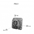
- the pose, in particular, the orientation, of the charging socket may be represented by rotational angle values with respect to three axes, i.e., a roll, a pitch, and a yaw as shown in FIG. 2 .
- rotational angle values with respect to three axes, i.e., a roll, a pitch, and a yaw as shown in FIG. 2 .
- FIG. 2 there exist various types of charging sockets as shown in FIG.
- IEC 62196 Plugs, socket-outlets, vehicle connectors and vehicle inlets - Conductive charging of electric vehicles
- IEC International Electrotechnical Commission
- J1772 SAE Electric Vehicle and Plug in Hybrid Electric Vehicle Conductive Charge Coupler
- 'CHAdeMO' IEEE Standard Technical Specifications of a DC Quick Charger for Use with Electric Vehicles
- CCS Combined Charging System
- FIG. 4 a block diagram illustrating a process of estimating a pose of a charging socket of an electric vehicle according to an exemplary embodiment of the present disclosure.
- an estimation device may determine an optimal pose of the charging socket of the electric vehicle based on an RGB image and a depth map of the charging socket which may be acquired based on images received from an image sensor (S100) by detecting a charging socket and at least one keypoint of the charging socket in the RGB image (S200), determining a first estimated pose of the charging socket based on the depth map (S300), and determining a second estimated pose of the charging socket by taking into account the keypoint of the charging socket and the first estimated pose (S400).
- the image sensor may include a three-dimensional (3D) camera such as a stereoscopic camera.
- the charging socket may be detected within a bounding box after the bounding box is set in the RGB image (S220).
- the keypoint (y i ) of the charging socket may be detected using the depth map and the bounding box (S240).
- the setting of the bounding box and the detection of the keypoint (y i ) may be performed by an artificial neural network.
- FIG. 5A shows an example of the bounding box set in the RGB image according to an exemplary embodiment of the present disclosure
- FIG. 5B is shows an example of the key points of the charging socket of the electric vehicle detected according to an exemplary embodiment of the present disclosure.
- the artificial neural network may include a charging socket detection neural network and a keypoint detection neural network.
- the charging socket detection neural network may be a convolutional neural network (CNN) using the RGB image as an input.
- the keypoint detection neural network may be a CNN using the RGB image as an input.
- the neural network for detecting the charging socket and the keypoint may be configured in a form of a cascade of two separate networks, that is, the charging socket detection neural network and the keypoint detection neural network.
- the charging socket detection neural network may be learnable, and may generate a charging socket detection model through a learning.
- the charging socket detection neural network may have a structure in which MobileNetV3 ( A, Howard et al., Searching for MobileNetV3, Proceedings of the IEEE/CVF International Conference on Computer Vision (ICCV), 2019, pp. 1314-1324 ) is employed as a backbone and MnasFPN ( Bo Chen et al., MnasFPN: Learning Latency-Aware Pyramid Architecture for Object Detection on Mobile Devices, Proceedings of the IEEE/CVF Conference on Computer Vision and Pattern Recognition (CVPR), 2020, pp. 13607-13616 ) is employed as a detection head.
- MobileNetV3 A, Howard et al., Searching for MobileNetV3, Proceedings of the IEEE/CVF International Conference on Computer Vision (ICCV), 2019, pp. 1314-1324
- MnasFPN Bo Chen et al., MnasFPN: Learning Latency-Aware Pyramid Architecture for
- data augmentation may be performed first on the RGB image to increase an amount of training data by adding slightly modified copies of existing data or newly created synthetic data from the existing data and thereby to increase a performance of a neural network model.
- the augmented data is fed to the charging socket detection neural network, so that the charging socket detection neural network processes the augmented data to set the bounding box, detect the charging socket within the bounding box, and calculate a confidence score indicating a similarity between the detected charging socket image and an actual charging socket image.
- the charging socket detection neural network may generate a location and size of the bounding box, the confidence score, and a class indicating the type of the charging socket as shown in FIG. 6 .
- the bounding box of the charging socket may be derived by optimizing a first objective function expressed by Equation 1 based on the information on the bounding box and the class, and ground truth by the charging socket detection neural network.
- L xclg 1 N L conf x c + ⁇ L loc x l g
- the first objective function may be interpreted as a combination of a first loss function expressed by Equation 2 and related with a classification loss for the class information and a second loss function expressed by Equation 3 and related with a regression loss for the bounding box.
- L conf x c ⁇ ⁇ i ⁇ Pos N x ij p log c ⁇ i p ⁇ ⁇ i ⁇ Neg log c ⁇ i 0
- c ⁇ i p exp c i p ⁇ p exp c i p
- loc x l g ⁇ i ⁇ Pos N ⁇ m ⁇ cx cy w h x ij k smooth L 1 l i m ⁇ g ⁇ i j
- smooth L 1 x ⁇ 0.5 x 2 if x ⁇ 1 x ⁇ 0.5 otherwise
- the charging socket detection model generated through such a training process enables to derive a plurality of bounding boxes based on the RGB image acquired based on the images from the image sensor. Some bounding boxes overlapping another ones among the plurality of bounding boxes may be removed by a non-maximum suppression (NMS) algorithm, for example.
- NMS non-maximum suppression
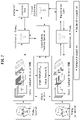
- FIG. 7 is a block diagram of a model for detecting the keypoint of the electric vehicle charging socket according to an exemplary embodiment of the present disclosure.
- the keypoint detection neural network may include a convolutional pose machine (CPM) as a backbone and may use a learnable optical flow operation module to estimate a motion between frames.
- the optical flow operation module may be a Lucas-Kanade optical flow algorithm.
- the keypoint detection neural network may be learnable, and may generate a keypoint detection model through a learning.
- the keypoint detection neural network may receive two consecutive frames from the sensor and derive coordinates of the keypoint (y i ) of the charging socket based on the received frames by the convolutional pose machine.
- a first frame earlier one of the two consecutive frames may be referred to as a first frame while the other frame may be referred to as a second frame.
- the first frame may be labeled but the second frame may not be labeled.
- a third loss function expressed by Equation 4 may be calculated based on the coordinates of the keypoints output by the convolutional pose machine for the first frame and ground truth coordinates.
- the coordinates of the keypoint in the second frame may be estimated by Equation 5 by applying the coordinates of the keypoint in the first frame and feature maps of the first and second frames to the optical flow module.
- the keypoint detection model may be generated by performing the learning such that the second objective function expressed by Equation 6 is optimized.
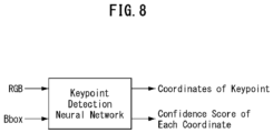
- FIG. 8 illustrates input and output of the keypoint detection model during an operation of the keypoint detection neural network according to an exemplary embodiment of the present disclosure.
- the keypoint detection model may receive a single RGB image frame, unlike the learning process, and the bounding box information to calculate and output the coordinates of the keypoint (y i ) and a confident score for each coordinate by using only the convolutional pose machine.
- the operation of determining the first estimated pose of the charging socket based on the depth map may include correcting the depth map (S320), deriving an equation of a plane of, e.g., a front face (but not limited thereto) of the charging socket based on a corrected depth map (S340), and deriving a transformation matrix through a rigid transformation (S360) to determine the first estimated pose of the charging socket.
- FIG. 9A is an example of the depth map before the correction according to an exemplary embodiment of the present disclosure
- FIG. 9B is an example of the depth map after the correction according to an exemplary embodiment of the present disclosure.
- the depth map of the charging socket may be inaccurate due to a shape of the charging socket having a plurality of deep and dark inlets.
- the depth map inside the bounding box may be corrected by performing interpolations based on depth values of points outside the bounding box (S320).
- the depth map shown in FIG. 9A may be corrected through the interpolation to the depth map shown in FIG. 9B .
- the equation of the plane may be derived by sampling some points inside a corrected depth map and applying a least squares minimization method using coordinates of sampled points.
- Equation 8 may be transformed into Equation 9 having a reduced dimension through a singular value decomposition (SVD), and the normal vector ' n ⁇ ' and a constant 'd' may be derived from a last column vector of the a unitary matrix 'V'.
- the keypoint (y i ) may be projected onto the plane described above by using an internal parameter K of the camera, the normal vector n ⁇ , and the constant d to obtain projected coordinates (p i ). Meanwhile, reference coordinates (q i ) which correspond to the keypoint (y i ) shown in FIG. 5B may be extracted from a CAD model of the charging socket.
- FIG. 10 is a graphical representation of examples of the reference coordinates according to an exemplary embodiment of the present disclosure.
- an initial transformation matrix (R°, t°) may be calculated through an operation of minimizing a third objective function expressed by Equation 10 which is written in terms of the projected coordinates (p i ) and the reference coordinates (q i ).
- the operation of determining the second estimated pose by taking into account the keypoint (S400) may include a sensor integration-based pose estimation operation, i.e., determining the second estimated pose of the charging socket based on all the sensor information including the keypoint (y i ) and the first estimated pose.
- the transformation matrix calculated by the Equation 10 is corrected and an optimal transformation matrix (R ⁇ , t ⁇ ) is derived by minimizing a fourth objective function expressed by Equation 11 which is written in terms of the keypoint (y i ) and the reference coordinates (q i ) corresponding to the keypoint (y i ).
- the initial transformation matrix (R°, t°) may be used for the initial value for the optimal transformation matrix (R ⁇ , t ⁇ ).
- the second estimated pose may be derived by correcting the first estimated pose to reduce an estimation error.
- FIGS. 11A and 11B are examples of screenshots of a simulator estimating the pose of the charging socket by the estimation method according to an exemplary embodiment of the present disclosure.
- the pose of the charging socket may be estimated while translating or panning and/or tilting the charging socket. Alternatively, however, the pose of the charging socket may be estimated while moving the camera instead of the charging socket.
- the image in a central left portion is an image assumed to be acquired by an RGB camera
- the image in a central right portion is an image assumed to be acquired by an RGB-Depth (RGB-D) camera.
- Pitch and yaw values of the charging socket calculated based on the ground truth, the RGB image, and the RGB-D image may be displayed on a lower portion of a screen of the simulator.
- Tables 1 and 2 summarizingly show results of quantitative experiments for estimating the pose of the charging socket based on the 3D camera image with the results according to a conventional method.
- the conventional method represents a method of estimating the pose using the RGB image only while the method of the present disclosure represents the method of estimating the pose using the RGB image along with the depth map.
- [Table 1] Mean Pitch Error (degree) -20° -10° 0° 10° 20° Avg.
- the method of estimating the pose of the electric vehicle charging socket according to the present embodiment using the 3D camera image was found to reduce an average pitch error from 3.12 degrees to 1.38 degrees and reduce an average yaw error from 4.55 degrees to 1.31 degrees in an example.
- FIG. 12 is a functional block diagram of an autonomous electric vehicle charging robot according to an exemplary embodiment of the present disclosure
- FIG. 13 is a schematic diagram depicting an overall function of the autonomous charging robot
- FIG. 14 is a flow chart showing an operation of the autonomous charging robot.
- the autonomous charging robot may include an image sensor 100, an image acquirer 210, a pose estimator 220, an actuation controller 230, and a manipulator 300.
- the image acquirer 210, the pose estimator 220, and the actuation controller 230 may be implemented by a program instructions executed by a processor, but the present disclosure is not limited thereto.
- a combination of the pose estimator 220 and the actuation controller 230 may be referred to as a robot controller.
- the robot controller may include a processor and an associated non-transitory memory storing software instructions which, when executed by the processor, provides the functionalities of the pose estimator 220 and the actuation controller 230.
- the processor may take the form of one or more processor(s) and associated memory storing program instructions.
- the image sensor 100 may acquire the RGB image and a depth map of the charging socket and its surroundings.
- the image sensor 100 may be a stereoscopic camera capable of acquiring a stereoscopic image of the charging socket and its surroundings.
- the image acquirer 210 may acquire the RGB image and the depth map of the charging socket and its surroundings from the image sensor 100. In an exemplary embodiment, the image acquirer 210 may directly receive the RGB image and the depth map from the image sensor 100. In an alternative embodiment where the image sensor 100 acquires the stereoscopic image, the image acquirer 210 may receive the stereoscopic image from the image sensor 100 and generate the RGB image and the depth map from the stereoscopic image.
- the pose estimator 220 may estimate the pose of the charging socket from the RGB image and the depth map.
- the actuation controller 230 may control a movement of the manipulator 300, so that a charging connector provided at, e.g., a front end of the manipulator 300, but not limited thereto, may be aligned with the charging socket of the electric vehicle.
- the manipulator 300 may be an articulated robot arm having six degrees of freedom, and may include a charging connector installed at, e.g., its front end.
- the image sensor 100 may be installed behind the charging connector on the manipulator 300.
- the manipulator 300 may align the charging connector to the charging socket of the electric vehicle and insert the charging connector into the charging socket under a control of the actuation controller 230 (S800).
- the pose estimator 220 estimates the pose of the charging socket through the artificial neural network.
- the actuation controller 230 may control the manipulator 300 based on the estimated pose of the charging socket, so that the charging connector may be aligned with the charging socket and inserted into the charging socket.
- the electric power may be supplied to the electric vehicle through the charging connector to charge a battery of the electric vehicle.
- the image acquirer 210 may acquire the RGB image and the depth map with an assistance of the image sensor 100 (S 100).
- the pose estimator 220 may detect the charging socket and the keypoint of the charging socket based on the RGB image and the depth map of the charging socket (S200), and may estimate the first estimated pose of the charging socket based on the depth map (S300).
- the pose estimator 220 may derive the second estimated pose by taking into account the keypoint of the charging socket and the first estimated pose of the charging socket (S400) using the optimally trained artificial neural network.
- the pose estimator 220 may determine whether the estimated pose of the charging socket satisfies a threshold and repeatedly estimate the pose of the charging socket until the threshold is satisfied (S500).
- the actuation controller 230 may determine a driving angle of each joint of the manipulator 300 by calculating the pose of the front end of the manipulator 300 where the charging connector is installed (S600). In addition, the actuation controller 230 may adjust the driving angle of each joint of the manipulator 300 to translate or rotate the manipulator 300. The actuation controller 230 may determine whether the charging connector and the charging socket at the front end of the manipulator 300 are aligned with each other (S700), and repeat the operation S600 until the charging connector and the charging socket are aligned with each other. When the charging connector is aligned with the charging socket of the electric vehicle, the manipulator 300 may insert the charging connector into the charging socket under the control of the actuation controller 230 (S800).
- FIG. 15 is a physical block diagram of the autonomous electric vehicle charging robot according to an exemplary embodiment of the present disclosure.
- the electric vehicle charging robot may include at least one processor 1010, a memory 1020 storing program instructions to be executed by the processor 1010 and a result of an instruction execution, and a storage 1060.
- the autonomous electric vehicle charging robot may further include an input interface device 1040, an output interface device 1050, and a data transceiver 1030.
- the components of the electric vehicle charging robot may be connected to each other by a bus 1070.
- the program instructions stored in the storage 1060 may be configured to cause the processor 1010 to acquire the RGB image and the depth map of the charging socket, detect the keypoint of the charging socket based on the RGB image, derive the first estimated pose of the charging socket based on the depth map, and derive the second estimated pose of the charging socket based on the keypoint of the charging socket and the first estimated pose.
- the program instructions may cause the processor 1010 to acquire the RGB image and the depth map with the assistance of the image sensor, detect the charging socket and the keypoint of the charging socket based on the RGB image of the charging socket, estimate the first estimated pose of the charging socket based on the depth map, derive the second estimated pose by taking into account the keypoint and the first estimated pose of the charging socket using the optimally trained artificial neural network, determine whether the estimated pose of the charging socket satisfies a threshold to repeatedly estimate the pose of the charging socket until the threshold is satisfied, determine the driving angle of each joint of the manipulator by calculating the pose of the front end of the manipulator where the charging connector is installed, adjust the driving angle of each joint of the manipulator to translate or rotate the manipulator, determine whether the charging connector and the charging socket are aligned with each other, repeat the adjustment of the driving angle until the charging connector and the charging socket are aligned with each other, and control the manipulator to insert the charging connector into the charging socket when the charging connector is aligned with the charging socket.
- the processor 1010 may execute program instructions stored in the memory 1020 or the storage 1060.
- the processor 1010 may include a central processing unit (CPU) or a graphics processing unit (GPU), or may be implemented by another kind of dedicated processor suitable for performing the method of the present disclosure.
- the memory 1020 may load the program instructions stored in the storage 760 to provide to the processor 1010 so that the processor 1010 may execute the program instructions.
- the memory 1020 may include, for example, a volatile memory such as a read only memory (ROM) and a nonvolatile memory such as a random access memory (RAM).
- ROM read only memory
- RAM random access memory
- the storage 1060 may include an intangible recording medium suitable for storing the program instructions, data files, data structures, and a combination thereof.
- the storage medium may include magnetic media such as a hard disk, a floppy disk, and a magnetic tape, optical media such as a compact disk read only memory (CD-ROM) and a digital video disk (DVD), magneto-optical medium such as a floptical disk, and semiconductor memories such as ROM, RAM, a flash memory, and a solid-state drive (SSD).
Landscapes
- Engineering & Computer Science (AREA)
- Mechanical Engineering (AREA)
- Robotics (AREA)
- Physics & Mathematics (AREA)
- Theoretical Computer Science (AREA)
- General Physics & Mathematics (AREA)
- Transportation (AREA)
- Power Engineering (AREA)
- Computer Vision & Pattern Recognition (AREA)
- Artificial Intelligence (AREA)
- Evolutionary Computation (AREA)
- Software Systems (AREA)
- Mathematical Physics (AREA)
- Computing Systems (AREA)
- Biophysics (AREA)
- Molecular Biology (AREA)
- General Health & Medical Sciences (AREA)
- Data Mining & Analysis (AREA)
- Health & Medical Sciences (AREA)
- Computational Linguistics (AREA)
- General Engineering & Computer Science (AREA)
- Biomedical Technology (AREA)
- Life Sciences & Earth Sciences (AREA)
- Automation & Control Theory (AREA)
- Human Computer Interaction (AREA)
- Fuzzy Systems (AREA)
- Image Analysis (AREA)
Abstract
Description
- The present disclosure relates to a method and device for charging an electric vehicle and, more particularly, to a method and device for estimating a pose of an electric vehicle charging socket using an image. Additionally, the present disclosure relates to a charging robot employing the method and device for estimating the pose of the electric vehicle charging socket.
- With rapid developments in electric vehicle-related technologies, electric vehicles are becoming more popular and charging infrastructure is being expanded widely. When an electric vehicle is to be charged by a conductive charging scheme at a charging station, a charging connector attached to a front end of a charging cable is drawn out from an electric vehicle supply equipment (EVSE) and moved and/or rotated to extend to the electric vehicle and coupled to a charging socket of the electric vehicle, and then electric power is transferred to the electric vehicle.
- Efforts to develop electric vehicle charging robots capable of automatically moving the charging connector and facilitating a support of the cable are underway. In order for an electric vehicle charging robot to accurately move the charging connector toward the charging socket of the electric vehicle and couple the charging connector to the charging socket, it is required to recognize not only a distance from the charging connector to the charging socket but also an orientation of the charging socket. However, it is very difficult to accurately estimate the orientation of the charging socket based on an image due to a variety of types of the charging sockets as well as a complex shape of each charging socket having a plurality of inlets.
- The information disclosed in the Background section above is to aid in the understanding of the background of the present disclosure, and should not be taken as acknowledgement that this information forms any part of prior art.
- To solve the above problems, provided is a method of accurately estimating a pose of a charging socket of an electric vehicle regardless of a shape of the charging socket, so that an electric vehicle charging robot may precisely move a charging connector toward the charging socket of the electric vehicle and couple the charging connector to the charging socket.
- Provided is a device for accurately estimating the pose of the charging socket of the electric vehicle regardless of the shape of the charging socket, so that the electric vehicle charging robot may precisely move the charging connector toward the charging socket of the electric vehicle and couple the charging connector to the charging socket.
- Provided is an autonomous electric vehicle charging robot capable of accurately estimating the pose of the charging socket of the electric vehicle regardless of the shape of the charging socket and precisely coupling the charging connector to the charging socket of the electric vehicle.
- According to an aspect of an exemplary embodiment, provided is a method of estimating a pose of a charging socket of an electric vehicle in an autonomous electric vehicle charging robot. The method includes: acquiring, by a processor, an RGB image and a depth map of the charging socket; detecting, by the processor, a keypoint of the charging socket based on the RGB image; deriving, by the processor, a first estimated pose of the charging socket based on the depth map; and deriving, by the processor, a second estimated pose of the charging socket based on the keypoint of the charging socket and the first estimated pose.
- The operation of detecting the keypoint of the charging socket based on the RGB image may include: detecting a bounding box surrounding the charging socket, calculating a confidence score for coordinates of the bounding box, and determining a class indicating a type of the charging socket by a learnable charging socket detection neural network; and detecting the keypoint inside a charging socket region in the bounding box by a learnable keypoint detection neural network.
- The charging socket detection neural network may include a MobileNetV3 as a backbone and a MnasFPN as a detection head.
- The operation of detecting the bounding box surrounding the charging socket may include removing at least one bounding box overlapping another bounding box among a plurality of bounding boxes detected by the charging socket detection neural network by a non-maximum suppression.
- The keypoint detection neural network may detect the keypoint based on a single RGB image and the bounding box by using only a convolutional pose machine during an actual operation after a learning.
- The operation of deriving the first estimated pose of the charging socket based on the depth map may include: correcting the depth map of the charging socket; deriving an equation of a plane of the charging socket by sampling a plurality of points inside a corrected depth map; projecting the keypoint of the charging socket onto the plane to acquire projected coordinates; acquiring reference coordinates corresponding to the projection coordinates from a CAD model of the charging socket; and acquiring an initial transformation matrix minimizing an objective function expressed by a following equation.

- The operation of deriving the second estimated pose of the charging socket may include deriving an optimal transformation matrix minimizing an objective function expressed by a following equation using the initial transformation matrix as an initial value.

- According to another aspect of an exemplary embodiment, provided is a device for estimating a pose of a charging socket of an electric vehicle in an autonomous electric vehicle charging robot. The device includes a processor and a memory storing program instructions executable by the processor. When executed by the processor, the program instructions cause the processor to acquire an RGB image and a depth map of the charging socket; detect a keypoint of the charging socket based on the RGB image; derive a first estimated pose of the charging socket based on the depth map; and derive a second estimated pose of the charging socket based on the keypoint of the charging socket and the first estimated pose.
- The program instructions causing the processor to detect the keypoint of the charging socket based on the RGB image may include instructions causing the processor to: detect a bounding box surrounding the charging socket, a confidence score for coordinates of the bounding box, and a class indicating a type of the charging socket by a learnable charging socket detection neural network; and detect the keypoint inside a charging socket region in the bounding box by a learnable keypoint detection neural network.
- The charging socket detection neural network may include a MobileNetV3 as a backbone and a MnasFPN as a detection head.
- The program instructions causing the processor to detect the bounding box surrounding the charging socket may include instructions causing the processor to remove at least one bounding box overlapping another bounding box among a plurality of bounding boxes detected by the charging socket detection neural network by a non-maximum suppression.
- The keypoint detection neural network may detect the keypoint based on a single RGB image and the bounding box by using only a convolutional pose machine during an actual operation after a learning.
- The program instructions causing the processor to derive the first estimated pose of the charging socket based on the depth map may include instructions causing the processor to: correct the depth map of the charging socket; derive an equation of a plane of the charging socket by sampling a plurality of points inside a corrected depth map; project the keypoint of the charging socket onto the plane to acquire projected coordinates; acquire reference coordinates corresponding to the projection coordinates from a CAD model of the charging socket; and acquire an initial transformation matrix minimizing an objective function expressed by a following equation.

- The program instructions causing the processor to derive the second estimated pose of the charging socket may include instructions causing the processor to derive an optimal transformation matrix minimizing an objective function expressed by a following equation using the initial transformation matrix as an initial value.

- According to an aspect of an exemplary embodiment, an autonomous electric vehicle charging robot includes: a manipulator having six degrees of freedom and configured to be controllable to insert a charging connector installed at a front end into a charging socket of an electric vehicle; an image acquirer configured to acquire an RGB image and a depth map of the charging socket; and a robot controller configured to estimate a pose of the charging socket, determine a driving angle of each joint of the manipulator based on an estimated pose of the charging socket, determine whether the charging connector and the charging socket are aligned with each other, and control the manipulator.
- The robot controller may include: a processor and a memory storing program instructions executable by the processor, wherein the program instructions, when executed by the processor, cause the processor to: acquire an RGB image and a depth map of the charging socket through the image acquirer; detect a keypoint of the charging socket based on the RGB image; derive a first estimated pose of the charging socket based on the depth map; and derive a second estimated pose of the charging socket based on the keypoint of the charging socket and the first estimated pose.
- According to an exemplary embodiment, the pose of the charging socket of the electric vehicle may be estimated precisely based on images acquired by a three-dimensional (3D) camera. The estimation device may be implemented economically because the device may be configured using a low-cost 3D camera without any additional sensor. In addition, the estimation method of the present disclosure is applicable regardless of the shape of the charging socket.
- According to another exemplary embodiment, a time required for moving the charging connector toward the charging socket of the electric vehicle to couple the charging connector to the charging socket may be reduced since the robot arms may be actuated based on an accurate pose information of the charging socket, which may enhance an operational efficiency of the charging robot.
- In order that the disclosure may be well understood, there will now be described various forms thereof, given by way of example, reference being made to the accompanying drawings, in which:
-
FIG. 1 illustrates a movement of a charging connector of an autonomous electric vehicle charging robot during a charging process according to an exemplary embodiment of the present disclosure; -
FIG. 2 shows an example of rotation angle values that may be used to represent an orientation of a charging socket of an electric vehicle; -
FIG. 3 shows examples of several types of the charging socket of the electric vehicle; -
FIG. 4 a block diagram illustrating a process of estimating the pose of the charging socket of the electric vehicle according to an exemplary embodiment of the present disclosure; -
FIG. 5A shows an example of the bounding box set in an RGB image according to an exemplary embodiment of the present disclosure; -
FIG. 5B shows an example of key points of the charging socket of the electric vehicle detected according to an exemplary embodiment of the present disclosure. -
FIG. 6 illustrates input and output of a charging socket detection model according to an exemplary embodiment of the present disclosure; -
FIG. 7 is a block diagram of a model for detecting the keypoint of the electric vehicle charging socket according to an exemplary embodiment of the present disclosure; -
FIG. 8 illustrates input and output of the keypoint detection model during an operation of the keypoint detection neural network according to an exemplary embodiment of the present disclosure; -
FIG. 9A is an example of a depth map before a correction according to an exemplary embodiment of the present disclosure; -
FIG. 9B is an example of a depth map after the correction according to an exemplary embodiment of the present disclosure; -
FIG. 10 is a graphical representation of examples of the reference coordinates according to an exemplary embodiment of the present disclosure; -
FIGS. 11A and 11B are examples of screenshots of a simulator estimating the pose of the charging socket by the estimation method according to an exemplary embodiment of the present disclosure; -
FIG. 12 is a functional block diagram of an autonomous electric vehicle charging robot according to an exemplary embodiment of the present disclosure; -
FIG. 13 is a schematic diagram depicting an overall function of the autonomous charging robot ofFIG. 12 ; -
FIG. 14 is a flow chart showing an operation of the autonomous charging robot ofFIG. 12 ; and -
FIG. 15 is a physical block diagram of the autonomous electric vehicle charging robot according to an exemplary embodiment of the present disclosure. - The drawings described herein are for illustration purposes only and are not intended to limit the scope of the present disclosure in any way.
- For a more clear understanding of the features and advantages of the present disclosure, exemplary embodiments of the present disclosure will be described in detail with reference to the accompanied drawings. However, it should be understood that the present disclosure is not limited to particular embodiments disclosed herein but includes all modifications, equivalents, and alternatives falling within the spirit and scope of the present disclosure. In the drawings, similar or corresponding components may be designated by the same or similar reference numerals.
- The terminologies including ordinals such as "first" and "second" designated for explaining various components in this specification are used to discriminate a component from the other ones but are not intended to be limiting to a specific component. For example, a second component may be referred to as a first component and, similarly, a first component may also be referred to as a second component without departing from the scope of the present disclosure. As used herein, the term "and/or" may include a presence of one or more of the associated listed items and any and all combinations of the listed items.
- In the present disclosure, expressions "at least one of A and B" and "at least one of A or B" may mean a group consisting of: "A", "B", or "both A and B". Also, expressions "one or more of A and B" and "one or more of A or B" may mean a group consisting of: "A", "B", or "both A and B".
- When a component is referred to as being "connected" or "coupled" to another component, the component may be directly connected or coupled logically or physically to the other component or indirectly through an object therebetween. Contrarily, when a component is referred to as being "directly connected" or "directly coupled" to another component, it is to be understood that there is no intervening object between the components. Other words used to describe the relationship between elements should be interpreted in a similar fashion.
- The terminologies are used herein for the purpose of describing particular exemplary embodiments only and are not intended to limit the present disclosure. The singular forms include plural referents as well unless the context clearly dictates otherwise. Also, the expressions "comprises," "includes," "constructed," "configured" are used to refer a presence of a combination of stated features, numbers, processing steps, operations, elements, or components, but are not intended to preclude a presence or addition of another feature, number, processing step, operation, element, or component.
- Spatially relative terms such as "below", "beneath", "lower", "above", "upper", and so on may be used to easily describe a relative position or direction with respect to a component. The terms, however, should not be regarded to designate an absolute position or direction of related objects. For example, when a component shown in the drawing is turned over, a component described to be placed "below" or "beneath" another component may be placed "above" or "on" the other component. Accordingly, the preposition "below", for example, may include both directions of "below" and "above". Thus, the prepositions of places and direction usage may also be constructed to indicate another positions or directions, and the components in the descriptions of positions and directions may be constructed to be in the other positions and directions or orientations.
- Unless defined otherwise, all terms used herein, including technical or scientific terms, have the same meaning as commonly understood by those of ordinary skill in the art to which the present disclosure pertains. Terms such as those defined in a commonly used dictionary should be interpreted as having meanings consistent with their meanings in the context of related literatures and will not be interpreted as having ideal or excessively formal meanings unless explicitly defined in the present application.
- Exemplary embodiments of the present disclosure will now be described in detail with reference to the accompanying drawings. In the following description and the accompanied drawings, detailed descriptions of well-known functions or configuration that may obscure the subject matter of the present disclosure will be omitted for simplicity. Also, it is to be noted that the same components are designated by the same reference numerals throughout the drawings.
-
FIG. 1 illustrates a movement of a charging connector of an autonomous electric vehicle charging robot during a charging process. The autonomous charging robot may recognize a pose of a charging socket of an electric vehicle parked in a charging station. In this specification including the appended claims, the term "pose" of the charging socket is used to refer at least an orientation of the charging socket. Also, the term "pose" may be used to refer the orientation as well as a relative position of the charging socket. The autonomous charging robot may control its robot joints to automatically move a charging connector of the charging robot so that the charging connector is coupled to the charging socket of the electric vehicle without a manipulation of an operator. The movement of the charging connector may include a translation and rotation. For example, as shown inFIG. 1 , the autonomous charging robot may translate the charging connector to a front of the charging socket of the electric vehicle, rotate the charging connector to face the charging socket, and then translate the charging connector forward again to be coupled to the charging socket. - In order to couple the charging connector to the charging socket as shown in
FIG. 1 precisely and safely, the autonomous charging robot should be able to accurately recognize the pose of the charging socket of the electric vehicle in addition to a type and shape of the charging socket and a distance from the charging connector to the charging socket. The pose, in particular, the orientation, of the charging socket may be represented by rotational angle values with respect to three axes, i.e., a roll, a pitch, and a yaw as shown inFIG. 2 . However, there exist various types of charging sockets as shown inFIG. 3 depending on their applications according to relevant industrial standards such as IEC 62196 (Plugs, socket-outlets, vehicle connectors and vehicle inlets - Conductive charging of electric vehicles) standard established by International Electrotechnical Commission (IEC), J1772 (SAE Electric Vehicle and Plug in Hybrid Electric Vehicle Conductive Charge Coupler) standard established by SAE International, IEEE Standard Technical Specifications of a DC Quick Charger for Use with Electric Vehicles ('CHAdeMO') standard established by IEEE, Combined Charging System (CCS) 1.0 Specification established by European and North American automotive manufacturers. The variety of the types of the charging sockets makes it more difficult to recognize the pose of the charging socket and may require a plurality of devices for recognizing the pose of the charging socket to be prepared in each charging station. Thus, it is needed to develop a versatile device capable of recognizing the pose including the relative position and the orientation of the charging socket regardless of the type of charging socket. -
FIG. 4 a block diagram illustrating a process of estimating a pose of a charging socket of an electric vehicle according to an exemplary embodiment of the present disclosure. According to the method of estimating the pose of the charging socket shown inFIG. 4 , an estimation device may determine an optimal pose of the charging socket of the electric vehicle based on an RGB image and a depth map of the charging socket which may be acquired based on images received from an image sensor (S100) by detecting a charging socket and at least one keypoint of the charging socket in the RGB image (S200), determining a first estimated pose of the charging socket based on the depth map (S300), and determining a second estimated pose of the charging socket by taking into account the keypoint of the charging socket and the first estimated pose (S400). Here, the image sensor may include a three-dimensional (3D) camera such as a stereoscopic camera. - In the operation S200, the charging socket may be detected within a bounding box after the bounding box is set in the RGB image (S220). In addition, the keypoint (yi) of the charging socket may be detected using the depth map and the bounding box (S240). The setting of the bounding box and the detection of the keypoint (yi) may be performed by an artificial neural network.
FIG. 5A shows an example of the bounding box set in the RGB image according to an exemplary embodiment of the present disclosure, andFIG. 5B is shows an example of the key points of the charging socket of the electric vehicle detected according to an exemplary embodiment of the present disclosure. - The artificial neural network may include a charging socket detection neural network and a keypoint detection neural network. The charging socket detection neural network may be a convolutional neural network (CNN) using the RGB image as an input. Also, the keypoint detection neural network may be a CNN using the RGB image as an input. The neural network for detecting the charging socket and the keypoint may be configured in a form of a cascade of two separate networks, that is, the charging socket detection neural network and the keypoint detection neural network.
- The charging socket detection neural network may be learnable, and may generate a charging socket detection model through a learning. In an exemplary embodiment, the charging socket detection neural network may have a structure in which MobileNetV3 (A, Howard et al., Searching for MobileNetV3, Proceedings of the IEEE/CVF International Conference on Computer Vision (ICCV), 2019, pp. 1314-1324) is employed as a backbone and MnasFPN (Bo Chen et al., MnasFPN: Learning Latency-Aware Pyramid Architecture for Object Detection on Mobile Devices, Proceedings of the IEEE/CVF Conference on Computer Vision and Pattern Recognition (CVPR), 2020, pp. 13607-13616) is employed as a detection head.
- During a learning or training process for the charging socket detection neural network, data augmentation may be performed first on the RGB image to increase an amount of training data by adding slightly modified copies of existing data or newly created synthetic data from the existing data and thereby to increase a performance of a neural network model. Afterwards, the augmented data is fed to the charging socket detection neural network, so that the charging socket detection neural network processes the augmented data to set the bounding box, detect the charging socket within the bounding box, and calculate a confidence score indicating a similarity between the detected charging socket image and an actual charging socket image. The charging socket detection neural network may generate a location and size of the bounding box, the confidence score, and a class indicating the type of the charging socket as shown in
FIG. 6 . - The bounding box of the charging socket may be derived by optimizing a first objective function expressed by
Equation 1 based on the information on the bounding box and the class, and ground truth by the charging socket detection neural network.
- The first objective function may be interpreted as a combination of a first loss function expressed by
Equation 2 and related with a classification loss for the class information and a second loss function expressed byEquation 3 and related with a regression loss for the bounding box.


- The charging socket detection model generated through such a training process enables to derive a plurality of bounding boxes based on the RGB image acquired based on the images from the image sensor. Some bounding boxes overlapping another ones among the plurality of bounding boxes may be removed by a non-maximum suppression (NMS) algorithm, for example.
-
FIG. 7 is a block diagram of a model for detecting the keypoint of the electric vehicle charging socket according to an exemplary embodiment of the present disclosure. The keypoint detection neural network may include a convolutional pose machine (CPM) as a backbone and may use a learnable optical flow operation module to estimate a motion between frames. The optical flow operation module may be a Lucas-Kanade optical flow algorithm. - The keypoint detection neural network may be learnable, and may generate a keypoint detection model through a learning. During a learning process, the keypoint detection neural network may receive two consecutive frames from the sensor and derive coordinates of the keypoint (yi) of the charging socket based on the received frames by the convolutional pose machine. Here, earlier one of the two consecutive frames may be referred to as a first frame while the other frame may be referred to as a second frame. The first frame may be labeled but the second frame may not be labeled. A third loss function expressed by Equation 4 may be calculated based on the coordinates of the keypoints output by the convolutional pose machine for the first frame and ground truth coordinates.

- The coordinates of the keypoint in the second frame may be estimated by
Equation 5 by applying the coordinates of the keypoint in the first frame and feature maps of the first and second frames to the optical flow module.
- Finally, the keypoint detection model may be generated by performing the learning such that the second objective function expressed by Equation 6 is optimized.

-
FIG. 8 illustrates input and output of the keypoint detection model during an operation of the keypoint detection neural network according to an exemplary embodiment of the present disclosure. During the operation after the learning is completed, the keypoint detection model may receive a single RGB image frame, unlike the learning process, and the bounding box information to calculate and output the coordinates of the keypoint (yi) and a confident score for each coordinate by using only the convolutional pose machine. - Referring back to
FIG. 4 , the operation of determining the first estimated pose of the charging socket based on the depth map may include correcting the depth map (S320), deriving an equation of a plane of, e.g., a front face (but not limited thereto) of the charging socket based on a corrected depth map (S340), and deriving a transformation matrix through a rigid transformation (S360) to determine the first estimated pose of the charging socket. -
FIG. 9A is an example of the depth map before the correction according to an exemplary embodiment of the present disclosure, andFIG. 9B is an example of the depth map after the correction according to an exemplary embodiment of the present disclosure. Referring toFIG. 9A , the depth map of the charging socket may be inaccurate due to a shape of the charging socket having a plurality of deep and dark inlets. To solve the problem, the depth map inside the bounding box may be corrected by performing interpolations based on depth values of points outside the bounding box (S320). For example, the depth map shown inFIG. 9A may be corrected through the interpolation to the depth map shown inFIG. 9B . - In the operation S340 of deriving the equation of the plane of the front face of the charging socket, the equation of the plane may be derived by sampling some points inside a corrected depth map and applying a least squares minimization method using coordinates of sampled points. The equation of the plane may be expressed by
Equation 7, where ' n̂ ' denotes a normal vector of the plane.
- The equation of the plane may be expressed in a matrix form of
Equation 8 to facilitate an application of the least squares minimization method, ' r̂i ' denotes a position vector of each pixel sampled in the corrected depth map image.
- The
Equation 8 may be transformed into Equation 9 having a reduced dimension through a singular value decomposition (SVD), and the normal vector ' n̂ ' and a constant 'd' may be derived from a last column vector of the a unitary matrix 'V'.
- The keypoint (yi) may be projected onto the plane described above by using an internal parameter K of the camera, the normal vector n̂ , and the constant d to obtain projected coordinates (pi). Meanwhile, reference coordinates (qi) which correspond to the keypoint (yi) shown in
FIG. 5B may be extracted from a CAD model of the charging socket.FIG. 10 is a graphical representation of examples of the reference coordinates according to an exemplary embodiment of the present disclosure. - In order to obtain a physical transformation relationship between the camera image and the charging socket, an initial transformation matrix (R°, t°) may be calculated through an operation of minimizing a third objective function expressed by
Equation 10 which is written in terms of the projected coordinates (pi) and the reference coordinates (qi).
- Referring back to
FIG. 4 , the operation of determining the second estimated pose by taking into account the keypoint (S400) may include a sensor integration-based pose estimation operation, i.e., determining the second estimated pose of the charging socket based on all the sensor information including the keypoint (yi) and the first estimated pose. In the sensor integration-based pose estimation operation, the transformation matrix calculated by theEquation 10 is corrected and an optimal transformation matrix (R∗, t∗) is derived by minimizing a fourth objective function expressed by Equation 11 which is written in terms of the keypoint (yi) and the reference coordinates (qi) corresponding to the keypoint (yi). At this time, the initial transformation matrix (R°, t°) may be used for the initial value for the optimal transformation matrix (R∗, t∗). Through the sensor integration-based pose estimation operation, the second estimated pose may be derived by correcting the first estimated pose to reduce an estimation error.
-
FIGS. 11A and 11B are examples of screenshots of a simulator estimating the pose of the charging socket by the estimation method according to an exemplary embodiment of the present disclosure. The pose of the charging socket may be estimated while translating or panning and/or tilting the charging socket. Alternatively, however, the pose of the charging socket may be estimated while moving the camera instead of the charging socket. InFIGS. 11A and 11B , the image in a central left portion is an image assumed to be acquired by an RGB camera, and the image in a central right portion is an image assumed to be acquired by an RGB-Depth (RGB-D) camera. Pitch and yaw values of the charging socket calculated based on the ground truth, the RGB image, and the RGB-D image may be displayed on a lower portion of a screen of the simulator. Tables 1 and 2 summarizingly show results of quantitative experiments for estimating the pose of the charging socket based on the 3D camera image with the results according to a conventional method. In the tables, the conventional method represents a method of estimating the pose using the RGB image only while the method of the present disclosure represents the method of estimating the pose using the RGB image along with the depth map.[Table 1] Mean Pitch Error (degree) -20° -10° 0° 10° 20° Avg. Conventional 1.58 2.35 3.22 4.81 3.63 3.12 Present 1.94 1.19 1.67 0.96 1.16 1.38 [Table 2] Mean Yaw Error (degree) -20° -10° 0° 10° 20° Avg. Conventional 2.14 2.90 7.29 6.37 4.03 4.55 Present 1.31 1.74 1.65 0.92 0.92 1.31 - Compared to the conventional method, the method of estimating the pose of the electric vehicle charging socket according to the present embodiment using the 3D camera image was found to reduce an average pitch error from 3.12 degrees to 1.38 degrees and reduce an average yaw error from 4.55 degrees to 1.31 degrees in an example.
-
FIG. 12 is a functional block diagram of an autonomous electric vehicle charging robot according to an exemplary embodiment of the present disclosure,FIG. 13 is a schematic diagram depicting an overall function of the autonomous charging robot, andFIG. 14 is a flow chart showing an operation of the autonomous charging robot. - The autonomous charging robot may include an
image sensor 100, animage acquirer 210, apose estimator 220, anactuation controller 230, and amanipulator 300. In an exemplary embodiment, theimage acquirer 210, thepose estimator 220, and theactuation controller 230 may be implemented by a program instructions executed by a processor, but the present disclosure is not limited thereto. In one exemplary embodiment, a combination of thepose estimator 220 and theactuation controller 230 may be referred to as a robot controller. For example, the robot controller may include a processor and an associated non-transitory memory storing software instructions which, when executed by the processor, provides the functionalities of thepose estimator 220 and theactuation controller 230. The processor may take the form of one or more processor(s) and associated memory storing program instructions. - The
image sensor 100 may acquire the RGB image and a depth map of the charging socket and its surroundings. Alternatively, theimage sensor 100 may be a stereoscopic camera capable of acquiring a stereoscopic image of the charging socket and its surroundings. - The
image acquirer 210 may acquire the RGB image and the depth map of the charging socket and its surroundings from theimage sensor 100. In an exemplary embodiment, theimage acquirer 210 may directly receive the RGB image and the depth map from theimage sensor 100. In an alternative embodiment where theimage sensor 100 acquires the stereoscopic image, theimage acquirer 210 may receive the stereoscopic image from theimage sensor 100 and generate the RGB image and the depth map from the stereoscopic image. Thepose estimator 220 may estimate the pose of the charging socket from the RGB image and the depth map. Theactuation controller 230 may control a movement of themanipulator 300, so that a charging connector provided at, e.g., a front end of themanipulator 300, but not limited thereto, may be aligned with the charging socket of the electric vehicle. - The
manipulator 300 may be an articulated robot arm having six degrees of freedom, and may include a charging connector installed at, e.g., its front end. Theimage sensor 100 may be installed behind the charging connector on themanipulator 300. Themanipulator 300 may align the charging connector to the charging socket of the electric vehicle and insert the charging connector into the charging socket under a control of the actuation controller 230 (S800). - Referring to
FIG. 13 , when the images around the socket is acquired through theimage sensor 100, thepose estimator 220 estimates the pose of the charging socket through the artificial neural network. Theactuation controller 230 may control themanipulator 300 based on the estimated pose of the charging socket, so that the charging connector may be aligned with the charging socket and inserted into the charging socket. In a state that the charging connector is inserted into the charging socket, the electric power may be supplied to the electric vehicle through the charging connector to charge a battery of the electric vehicle. - In detail, referring to
FIG. 14 , theimage acquirer 210 may acquire the RGB image and the depth map with an assistance of the image sensor 100 (S 100). Thepose estimator 220 may detect the charging socket and the keypoint of the charging socket based on the RGB image and the depth map of the charging socket (S200), and may estimate the first estimated pose of the charging socket based on the depth map (S300). Thepose estimator 220 may derive the second estimated pose by taking into account the keypoint of the charging socket and the first estimated pose of the charging socket (S400) using the optimally trained artificial neural network. Thepose estimator 220 may determine whether the estimated pose of the charging socket satisfies a threshold and repeatedly estimate the pose of the charging socket until the threshold is satisfied (S500). - The
actuation controller 230 may determine a driving angle of each joint of themanipulator 300 by calculating the pose of the front end of themanipulator 300 where the charging connector is installed (S600). In addition, theactuation controller 230 may adjust the driving angle of each joint of themanipulator 300 to translate or rotate themanipulator 300. Theactuation controller 230 may determine whether the charging connector and the charging socket at the front end of themanipulator 300 are aligned with each other (S700), and repeat the operation S600 until the charging connector and the charging socket are aligned with each other. When the charging connector is aligned with the charging socket of the electric vehicle, themanipulator 300 may insert the charging connector into the charging socket under the control of the actuation controller 230 (S800). -
FIG. 15 is a physical block diagram of the autonomous electric vehicle charging robot according to an exemplary embodiment of the present disclosure. - The electric vehicle charging robot according to the present embodiment may include at least one
processor 1010, amemory 1020 storing program instructions to be executed by theprocessor 1010 and a result of an instruction execution, and astorage 1060. The autonomous electric vehicle charging robot may further include aninput interface device 1040, anoutput interface device 1050, and adata transceiver 1030. The components of the electric vehicle charging robot may be connected to each other by abus 1070. - The program instructions stored in the
storage 1060 may be configured to cause theprocessor 1010 to acquire the RGB image and the depth map of the charging socket, detect the keypoint of the charging socket based on the RGB image, derive the first estimated pose of the charging socket based on the depth map, and derive the second estimated pose of the charging socket based on the keypoint of the charging socket and the first estimated pose. - The program instructions may cause the
processor 1010 to acquire the RGB image and the depth map with the assistance of the image sensor, detect the charging socket and the keypoint of the charging socket based on the RGB image of the charging socket, estimate the first estimated pose of the charging socket based on the depth map, derive the second estimated pose by taking into account the keypoint and the first estimated pose of the charging socket using the optimally trained artificial neural network, determine whether the estimated pose of the charging socket satisfies a threshold to repeatedly estimate the pose of the charging socket until the threshold is satisfied, determine the driving angle of each joint of the manipulator by calculating the pose of the front end of the manipulator where the charging connector is installed, adjust the driving angle of each joint of the manipulator to translate or rotate the manipulator, determine whether the charging connector and the charging socket are aligned with each other, repeat the adjustment of the driving angle until the charging connector and the charging socket are aligned with each other, and control the manipulator to insert the charging connector into the charging socket when the charging connector is aligned with the charging socket. - The
processor 1010 may execute program instructions stored in thememory 1020 or thestorage 1060. Theprocessor 1010 may include a central processing unit (CPU) or a graphics processing unit (GPU), or may be implemented by another kind of dedicated processor suitable for performing the method of the present disclosure. Thememory 1020 may load the program instructions stored in the storage 760 to provide to theprocessor 1010 so that theprocessor 1010 may execute the program instructions. Thememory 1020 may include, for example, a volatile memory such as a read only memory (ROM) and a nonvolatile memory such as a random access memory (RAM). - The
storage 1060 may include an intangible recording medium suitable for storing the program instructions, data files, data structures, and a combination thereof. Examples of the storage medium may include magnetic media such as a hard disk, a floppy disk, and a magnetic tape, optical media such as a compact disk read only memory (CD-ROM) and a digital video disk (DVD), magneto-optical medium such as a floptical disk, and semiconductor memories such as ROM, RAM, a flash memory, and a solid-state drive (SSD). - The description of the disclosure is merely exemplary in nature and, thus, variations that do not depart from the substance of the disclosure are intended to be within the scope of the disclosure. Such variations are not to be regarded as a departure from the spirit and scope of the disclosure. Thus, it will be understood by those of ordinary skill in the art that various changes in form and details may be made without departing from the spirit and scope as defined by the following claims.
Claims (14)
- A method of estimating a pose of a charging socket of an electric vehicle in an autonomous electric vehicle charging robot, the method comprising:acquiring, by a processor, an RGB image and a depth map of the charging socket;detecting, by the processor, a keypoint of the charging socket based on the RGB image;deriving, by the processor, a first estimated pose of the charging socket based on the depth map; andderiving, by the processor, a second estimated pose of the charging socket based on the keypoint of the charging socket and the first estimated pose.
- The method of claim 1, wherein the detecting a keypoint of the charging socket based on the RGB image comprises:detecting a bounding box surrounding the charging socket, calculating a confidence score for coordinates of the bounding box, and determining a class indicating a type of the charging socket by a learnable charging socket detection neural network; anddetecting the keypoint inside a charging socket region in the bounding box by a learnable keypoint detection neural network.
- The method of claim 2, wherein the charging socket detection neural network comprises a MobileNetV3 as a backbone and a MnasFPN as a detection head.
- The method of claim 2, wherein the detecting a bounding box surrounding the charging socket comprises:
removing at least one bounding box overlapping another bounding box among a plurality of bounding boxes detected by the charging socket detection neural network by a non-maximum suppression. - The method of claim 2, wherein the keypoint detection neural network detects the keypoint based on a single RGB image and the bounding box by using only a convolutional pose machine during an actual operation after a learning.
- The method of claim 1, wherein the deriving a first estimated pose of the charging socket based on the depth map comprises:correcting the depth map of the charging socket;deriving an equation of a plane of the charging socket by sampling a plurality of points inside a corrected depth map;projecting the keypoint of the charging socket onto the plane to acquire projected coordinates;acquiring reference coordinates corresponding to the projection coordinates from a CAD model of the charging socket; andacquiring an initial transformation matrix minimizing an objective function expressed by a following equation.

- The method of claim 6, wherein the deriving a second estimated pose of the charging socket comprises:
deriving an optimal transformation matrix minimizing an objective function expressed by a following equation using the initial transformation matrix as an initial value.
- A device for estimating a pose of a charging socket of an electric vehicle in an autonomous electric vehicle charging robot, comprising:a processor; anda memory storing program instructions executable by the processor,wherein the program instructions, when executed by the processor, cause the processor to:acquire an RGB image and a depth map of the charging socket;detect a keypoint of the charging socket based on the RGB image;derive a first estimated pose of the charging socket based on the depth map; andderive a second estimated pose of the charging socket based on the keypoint of the charging socket and the first estimated pose.
- The device of claim 8, wherein the program instructions causing the processor to detect the keypoint of the charging socket based on the RGB image comprises program instructions causing the processor to:detect a bounding box surrounding the charging socket, calculate a confidence score for coordinates of the bounding box, and determine a class indicating a type of the charging socket by a learnable charging socket detection neural network; anddetect the keypoint inside a charging socket region in the bounding box by a learnable keypoint detection neural network.
- The device of claim 9, wherein the charging socket detection neural network comprises a MobileNetV3 as a backbone and a MnasFPN as a detection head.
- The device of claim 9, wherein the program instructions causing the processor to detect the bounding box surrounding the charging socket comprises program instructions causing the processor to:
remove at least one bounding box overlapping another bounding box among a plurality of bounding boxes detected by the charging socket detection neural network by a non-maximum suppression. - The device of claim 9, wherein the keypoint detection neural network detects the keypoint based on a single RGB image and the bounding box by using only a convolutional pose machine during an actual operation after a learning.
- The device of claim 8, wherein the program instructions causing the processor to derive the first estimated pose of the charging socket based on the depth map comprises program instructions causing the processor to:correct the depth map of the charging socket;derive an equation of a plane of the charging socket by sampling a plurality of points inside a corrected depth map;project the keypoint of the charging socket onto the plane to acquire projected coordinates;acquire reference coordinates corresponding to the projection coordinates from a CAD model of the charging socket; andacquire an initial transformation matrix minimizing a third objective function expressed by a following equation.

- The device of claim 13, wherein the program instructions causing the processor to derive the second estimated pose of the charging socket comprises program instructions causing the processor to:
derive an optimal transformation matrix minimizing an objective function expressed by a following equation using the initial transformation matrix as an initial value.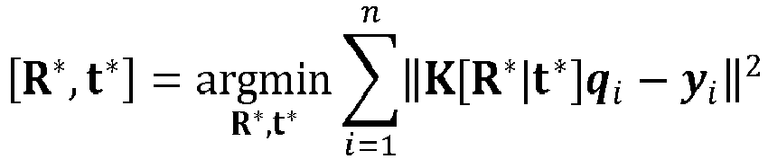
Applications Claiming Priority (1)
| Application Number | Priority Date | Filing Date | Title |
|---|---|---|---|
| KR1020210129254A KR20230046138A (en) | 2021-09-29 | 2021-09-29 | Method for estimating posture of electric vehicle charging socket and autonomous charging robot using the same |
Publications (1)
| Publication Number | Publication Date |
|---|---|
| EP4159385A1 true EP4159385A1 (en) | 2023-04-05 |
Family
ID=80930100
Family Applications (1)
| Application Number | Title | Priority Date | Filing Date |
|---|---|---|---|
| EP22163405.8A Pending EP4159385A1 (en) | 2021-09-29 | 2022-03-22 | Method and device for estimating pose of electric vehicle charging socket and autonomous charging robot employing the same |
Country Status (3)
| Country | Link |
|---|---|
| US (1) | US12115873B2 (en) |
| EP (1) | EP4159385A1 (en) |
| KR (1) | KR20230046138A (en) |
Families Citing this family (9)
| Publication number | Priority date | Publication date | Assignee | Title |
|---|---|---|---|---|
| DE102021212485B3 (en) * | 2021-11-05 | 2023-02-23 | Volkswagen Aktiengesellschaft | Method and device for autonomously plugging a charging connector into a charging socket of a vehicle |
| US20240140230A1 (en) * | 2022-10-28 | 2024-05-02 | Evjam Llc | Electric vehicle charging system with charging bus charging robot |
| KR102883255B1 (en) * | 2023-11-21 | 2025-11-07 | 성균관대학교산학협력단 | Electric vehicle robot charging system |
| KR102877370B1 (en) * | 2023-12-28 | 2025-10-29 | 주식회사 현대케피코 | Charging robot for charging an electric vehicle and operation method thereof |
| NL2036719B1 (en) * | 2023-12-29 | 2025-07-15 | Rocsys B V | System and method for supporting the autonomous charging of an electric vehicle |
| KR102890713B1 (en) * | 2024-01-03 | 2025-11-25 | 주식회사 현대케피코 | Method for controlling the coupling of a charging robot and a charging port of an electric vehicle |
| KR20260006289A (en) | 2024-07-04 | 2026-01-13 | 주식회사 현대케피코 | Charging Port Attitude Estimation Method and Apparatus |
| CN119305441A (en) * | 2024-12-18 | 2025-01-14 | 国网浙江省电力有限公司金华供电公司 | Automatic charging method and device based on 3D vision and force feedback control |
| CN120863391B (en) * | 2025-09-29 | 2025-12-12 | 重庆长安汽车股份有限公司 | Charging equipment, charging control method, device and medium thereof |
Citations (1)
| Publication number | Priority date | Publication date | Assignee | Title |
|---|---|---|---|---|
| WO2021155308A1 (en) * | 2020-01-29 | 2021-08-05 | Boston Polarimetrics, Inc. | Systems and methods for pose detection and measurement |
Family Cites Families (2)
| Publication number | Priority date | Publication date | Assignee | Title |
|---|---|---|---|---|
| DE102021109332B4 (en) * | 2021-04-14 | 2023-07-06 | Robert Bosch Gesellschaft mit beschränkter Haftung | Apparatus and method for controlling a robot to insert an object into an insertion site |
| US12065051B2 (en) * | 2021-05-05 | 2024-08-20 | ABB E-mobility B.V. | Systems and methods for electric vehicle charging using machine learning |
-
2021
- 2021-09-29 KR KR1020210129254A patent/KR20230046138A/en active Pending
-
2022
- 2022-03-18 US US17/698,352 patent/US12115873B2/en active Active
- 2022-03-22 EP EP22163405.8A patent/EP4159385A1/en active Pending
Patent Citations (1)
| Publication number | Priority date | Publication date | Assignee | Title |
|---|---|---|---|---|
| WO2021155308A1 (en) * | 2020-01-29 | 2021-08-05 | Boston Polarimetrics, Inc. | Systems and methods for pose detection and measurement |
Non-Patent Citations (11)
| Title |
|---|
| "Robotics : modelling, planning and control", 31 December 2009, SPRINGER, UK, ISBN: 978-1-84628-641-4, article BRUNO SICILIANO ET AL: "Visual Servoing", pages: 407 - 467, XP055460541, DOI: 10.1007/978-1-84628-642-1 * |
| A, HOWARD ET AL.: "Searching for MobileNetV3", PROCEEDINGS OF THE IEEE/CVF INTERNATIONAL CONFERENCE ON COMPUTER VISION, 2019, pages 1314 - 1324, XP033723291, DOI: 10.1109/ICCV.2019.00140 |
| ANONYMOUS ET AL: "A new machine vision highlight: MVTec HALCON 18.11 to be released on November 30", 2 October 2018 (2018-10-02), XP055952933, Retrieved from the Internet <URL:https://www.mvtec.com/services-support/videos-tutorials/single-video/halcon-1811-release> [retrieved on 20220818] * |
| ANONYMOUS: "A new machine vision highlight: MVTec HALCON 18.11 to be released on November 30", 2 October 2018 (2018-10-02), XP055952932, Retrieved from the Internet <URL:https://www.mvtec.com/services-support/videos-tutorials/single-video/halcon-1811-release> [retrieved on 20220818] * |
| BO CHEN ET AL.: "MnasFPN: Learning Latency-Aware Pyramid Architecture for Object Detection on Mobile Devices", PROCEEDINGS OF THE IEEE/CVF CONFERENCE ON COMPUTER VISION AND PATTERN RECOGNITION, 2020, pages 13607 - 13616 |
| CHEN BO ET AL: "MnasFPN: Learning Latency-Aware Pyramid Architecture for Object Detection on Mobile Devices", 2020 IEEE/CVF CONFERENCE ON COMPUTER VISION AND PATTERN RECOGNITION (CVPR), IEEE, 13 June 2020 (2020-06-13), pages 13604 - 13613, XP033805127, DOI: 10.1109/CVPR42600.2020.01362 * |
| HIRZ MARIO ET AL: "Autonomous Charging of Electric Vehicles in Industrial Environment", TEHNICKI GLASNIK, vol. 15, no. 2, 9 June 2021 (2021-06-09), pages 220 - 225, XP055952345, ISSN: 1846-6168, Retrieved from the Internet <URL:http://dx.doi.org/10.31803/tg-20210428191147> DOI: 10.31803/tg-20210428191147 * |
| JUSTINAS MISEIKIS ET AL: "3D Vision Guided Robotic Charging Station for Electric and Plug-in Hybrid Vehicles", ARXIV.ORG, CORNELL UNIVERSITY LIBRARY, 201 OLIN LIBRARY CORNELL UNIVERSITY ITHACA, NY 14853, 15 March 2017 (2017-03-15), XP080757309 * |
| PAN MINGQIANG ET AL: "Automatic recognition and location system for electric vehicle charging port in complex environment", IET IMAGE PROCESSING, IET, UK, vol. 14, no. 10, 21 August 2020 (2020-08-21), pages 2263 - 2272, XP006092988, ISSN: 1751-9659, DOI: 10.1049/IET-IPR.2019.1138 * |
| PENG JIANQING ET AL: "An Autonomous Pose Measurement Method of Civil Aviation Charging Port Based on Cumulative Natural Feature Data", IEEE SENSORS JOURNAL, IEEE, USA, vol. 19, no. 23, 1 December 2019 (2019-12-01), pages 11646 - 11655, XP011758127, ISSN: 1530-437X, [retrieved on 20191114], DOI: 10.1109/JSEN.2019.2934116 * |
| QUAN PENGKUN ET AL: "Research on Fast Identification and Location of Contour Features of Electric Vehicle Charging Port in Complex Scenes", IEEE ACCESS, vol. 10, 13 June 2021 (2021-06-13), pages 26702 - 26714, XP055952578, Retrieved from the Internet <URL:https://ieeexplore.ieee.org/ielx7/6287639/9668973/09464294.pdf?tp=&arnumber=9464294&isnumber=9668973&ref=aHR0cHM6Ly9pZWVleHBsb3JlLmllZWUub3JnL2Fic3RyYWN0L2RvY3VtZW50Lzk0NjQyOTQ=> DOI: 10.1109/ACCESS.2021.3092210 * |
Also Published As
| Publication number | Publication date |
|---|---|
| KR20230046138A (en) | 2023-04-05 |
| US12115873B2 (en) | 2024-10-15 |
| US20230102948A1 (en) | 2023-03-30 |
Similar Documents
| Publication | Publication Date | Title |
|---|---|---|
| EP4159385A1 (en) | Method and device for estimating pose of electric vehicle charging socket and autonomous charging robot employing the same | |
| CN116278880A (en) | A charging device and a method for controlling the charging of a mechanical arm | |
| US12361585B2 (en) | Feature detection for automated air-to-air refueling (A3R) | |
| Heng et al. | Camodocal: Automatic intrinsic and extrinsic calibration of a rig with multiple generic cameras and odometry | |
| US12333750B2 (en) | Systems and methods for generic visual odometry using learned features via neural camera models | |
| US20230191934A1 (en) | Method and device for detecting electric vehicle using external camera and electric vehicle charging robot using the same | |
| CN113978297B (en) | Electric automobile automatic charging system based on 3D vision and force compliance control | |
| CN116524128A (en) | Multi-view three-dimensional reconstruction and flexible docking method and system based on vision and force sense | |
| US20230215041A1 (en) | Pose estimation refinement for aerial refueling | |
| CN108151713A (en) | A kind of quick position and orientation estimation methods of monocular VO | |
| WO2022228391A1 (en) | Terminal device positioning method and related device therefor | |
| CN114771320A (en) | Charging system and method for active positioning and automatic access of charging connector | |
| JP2024503275A (en) | Mobile robot control method, computer-implemented storage medium, and mobile robot | |
| US20260014885A1 (en) | Determining feature poses of electric vehicles to automatically charge electric vehicles | |
| CN118201798A (en) | Method and device for autonomously inserting a charging plug into a charging socket of a vehicle | |
| US11645773B2 (en) | Method for acquiring distance from moving body to at least one object located in any direction of moving body by performing near region sensing and image processing device using the same | |
| US12487090B2 (en) | Map merging method for electronic apparatus | |
| CN115145258B (en) | Control device, control method, and storage medium | |
| CN120655722A (en) | Charging robot automobile charging port pose measuring method, charging method and charging system | |
| US11615544B2 (en) | Systems and methods for end-to-end map building from a video sequence using neural camera models | |
| CN116558522B (en) | A Large Scene Relocalization Method Based on Laser Vision Fusion Data | |
| CN119806157A (en) | A robot recharging method, device, equipment and storage medium | |
| US20230237761A1 (en) | Object extraction method and object extraction system using the same | |
| CN116081283A (en) | Method, system, device and medium for transporting hose into hole | |
| CN117994614A (en) | Target detection method and device |
Legal Events
| Date | Code | Title | Description |
|---|---|---|---|
| PUAI | Public reference made under article 153(3) epc to a published international application that has entered the european phase |
Free format text: ORIGINAL CODE: 0009012 |
|
| STAA | Information on the status of an ep patent application or granted ep patent |
Free format text: STATUS: THE APPLICATION HAS BEEN PUBLISHED |
|
| AK | Designated contracting states |
Kind code of ref document: A1 Designated state(s): AL AT BE BG CH CY CZ DE DK EE ES FI FR GB GR HR HU IE IS IT LI LT LU LV MC MK MT NL NO PL PT RO RS SE SI SK SM TR |
|
| P01 | Opt-out of the competence of the unified patent court (upc) registered |
Effective date: 20230526 |
|
| STAA | Information on the status of an ep patent application or granted ep patent |
Free format text: STATUS: REQUEST FOR EXAMINATION WAS MADE |
|
| 17P | Request for examination filed |
Effective date: 20231002 |
|
| RBV | Designated contracting states (corrected) |
Designated state(s): AL AT BE BG CH CY CZ DE DK EE ES FI FR GB GR HR HU IE IS IT LI LT LU LV MC MK MT NL NO PL PT RO RS SE SI SK SM TR |
|
| STAA | Information on the status of an ep patent application or granted ep patent |
Free format text: STATUS: EXAMINATION IS IN PROGRESS |
|
| 17Q | First examination report despatched |
Effective date: 20250205 |