EP4159375A1 - Impact tool - Google Patents
Impact tool Download PDFInfo
- Publication number
- EP4159375A1 EP4159375A1 EP21813492.2A EP21813492A EP4159375A1 EP 4159375 A1 EP4159375 A1 EP 4159375A1 EP 21813492 A EP21813492 A EP 21813492A EP 4159375 A1 EP4159375 A1 EP 4159375A1
- Authority
- EP
- European Patent Office
- Prior art keywords
- hammer
- anvil
- main body
- body part
- impact tool
- Prior art date
- Legal status (The legal status is an assumption and is not a legal conclusion. Google has not performed a legal analysis and makes no representation as to the accuracy of the status listed.)
- Pending
Links
Images




Classifications
-
- B—PERFORMING OPERATIONS; TRANSPORTING
- B25—HAND TOOLS; PORTABLE POWER-DRIVEN TOOLS; MANIPULATORS
- B25B—TOOLS OR BENCH DEVICES NOT OTHERWISE PROVIDED FOR, FOR FASTENING, CONNECTING, DISENGAGING, OR HOLDING
- B25B21/00—Portable power-driven screw or nut setting or loosening tools; Attachments for drilling apparatus serving the same purpose
- B25B21/02—Portable power-driven screw or nut setting or loosening tools; Attachments for drilling apparatus serving the same purpose with means for imparting impact to screwdriver blade or nut socket
- B25B21/026—Impact clutches
-
- B—PERFORMING OPERATIONS; TRANSPORTING
- B25—HAND TOOLS; PORTABLE POWER-DRIVEN TOOLS; MANIPULATORS
- B25B—TOOLS OR BENCH DEVICES NOT OTHERWISE PROVIDED FOR, FOR FASTENING, CONNECTING, DISENGAGING, OR HOLDING
- B25B21/00—Portable power-driven screw or nut setting or loosening tools; Attachments for drilling apparatus serving the same purpose
- B25B21/02—Portable power-driven screw or nut setting or loosening tools; Attachments for drilling apparatus serving the same purpose with means for imparting impact to screwdriver blade or nut socket
Definitions
- the present invention relates to an impact tool for fastening a fastener such as a screw or a bolt.
- Patent Document 1 As a power transmission mechanism, a striking mechanism is provided that converts a rotational force into a striking force in a rotation direction. In the striking mechanism, an anvil that outputs the rotational force to the tip tool and a collision part (claw part) of a hammer that imparts the striking force to the anvil are each provided in three places.
- Patent Document 1 WO 2016/002539
- the present invention has been made in view of the above background, and an object thereof is to provide an impact tool in which a stress generated in a joint between a main body part of a hammer and a striking claw is reduced. Another object of the present invention is to provide an impact tool with a reduced overall length and improved workability.
- an impact tool includes: a motor; a spindle, driven in a rotation direction by the motor; a hammer, relatively movable in an axial direction and a rotation direction within a predetermined range with respect to the spindle and energized forward by a cam mechanism and a spring; and an anvil, rotatably provided in front of the hammer and struck by the hammer when the hammer rotates while moving forward.
- the hammer is configured to include a main body part and a claw part extending forward from the main body part, and a front inner diameter side end of the main body part is configured to be located in front of a front outer diameter side end of the main body part.
- the main body part of the hammer includes a front wall, and the claw part has a shape protruding from the front wall toward the anvil as viewed in a rotation axis direction.
- a relationship between a length L1 of an inner diameter side front end of the claw part from the main body part and a length L2 of an outer diameter side front end of the claw part from the main body part is configured to satisfy L1 ⁇ L2.
- the main body part of the hammer is formed with a tapered surface that gradually recedes away from a rotation axis.
- an orthogonal plane orthogonal to the rotation axis is configured to be formed in the main body part of the hammer, and an axial length D1 of the hammer from the orthogonal plane to a rear end is configured to be greater than an axial length D2 of the hammer from the tapered surface to the rear end.
- a spring support for supporting the spring is configured to be formed on a side of the main body part of the hammer opposite the anvil, and the tapered surface is configured to extend from radially outside of a radial center position of the spring support.
- the cam mechanism is configured to include a spindle cam groove provided on the spindle, a hammer cam groove formed on an inner peripheral side of the hammer, a cam ball disposed between the spindle cam groove and the hammer cam groove, and a spring having a coil shape that is disposed around the spindle and energizes the hammer toward the anvil in a rotation axis direction.
- the motor of the impact tool is driven using a battery that is able to be used in a detachable electric tool as a driving power source.
- stress concentration in the vicinity of an outer diameter side end of a root of a hammer claw can be reduced.
- a striking mechanism can be made compact.
- FIG. 1 is a side view showing an appearance of an impact tool 1 according to an embodiment of the present invention.
- a battery 90 of a rechargeable pack type is used as a power source, a rotational force and a striking force are imparted to an output shaft (anvil 50) with a motor as a driving source, a rotational striking force is intermittently transmitted to a tip tool (not shown) such as a driver bit held in a mounting hole 53 by a mounting mechanism 60, and an operation such as screw fastening or bolt fastening is performed.
- a housing 2 of the impact tool 1 is formed in a substantially T-shape, including a tubular body 2a and a handle 2b, the body 2a having a substantially cylindrical shape for housing a motor and a power transmission mechanism, the handle 2b extending from the vicinity of a substantial center of the body 2a in a direction substantially orthogonal to a rotation axis A1 and being provided for an operator to grip with one hand.
- a lower end located on a side opposite the body located on a side opposite the body 2a has a battery attachment part 2c formed thereat.
- a trigger lever 7a is disposed in an upper part inside the handle 2b so as to protrude forward.
- a forward/reverse switching lever 8 for switching a rotation direction of a motor 3 between the forward direction and the reverse direction is provided on a rear side of the trigger lever 7a.
- the motor 3 is housed on the rear side of the tubular body 2a.
- the motor 3 is a DC (direct current) motor without a brush (rectifying brush), and is a 4-pole, 6-slot brushless DC motor.
- the motor 3 includes a rotor 3a including a permanent magnet and a stator 3b including a multi-phase armature winding (stator winding) such as a three-phase winding.
- the rotor 3a forms a magnetic path formed by the permanent magnet.
- the stator 3b is manufactured of a laminated structure of annular thin iron plates, and has six teeth (not shown) formed on the inner peripheral side thereof. An enameled wire is wound around each tooth to form a coil.
- the coil has a star connection or delta connection having three phases, namely, U phase, V phase, and W phase.
- the motor 3 is operated in the following manner. That is, a DC voltage supplied from a battery or the like is switched by a plurality of semiconductor switching elements 14 using an output of a position detector 13 composed of a plurality of Hall ICs that detect a magnetic force of the permanent magnet of the rotor 3a and detect a rotor position.
- the motor is a brushless motor in the present embodiment, the motor may also be a brushed motor.
- a rotation shaft 4 of the motor 3 is disposed concentrically with the rotation axis A1 of the tubular body 2a, and axially supported by the housing 2 by two bearings 16a and 16b on the front side and the rear side.
- a substantially annular inverter circuit board 12 for mounting three position detectors 13 and six semiconductor switching elements 14 or the like is disposed on the rear side of the stator 3b.
- the inverter circuit board 12 is a substantially annular double-sided board having approximately the same diameter as an outer diameter of the motor 3.
- Six semiconductor switching elements 14 are provided to form an inverter circuit and switch energization to the stator winding of each phase.
- a field-effect transistor (FET), an insulated gate bipolar transistor (IGBT) or the like may be used. Since the inverter circuit is controlled by a microcomputer and an energization timing of the armature winding of each phase is set based on a position detection signal for the rotor 3a by the position detector 13, advanced rotation control becomes easy.
- a cooling fan 15 is attached coaxially with the rotation shaft 4 between the rotor 3a and the bearing 16b.
- the cooling fan 15 is, for example, integrally molded by a plastic mold, sucks air from an air intake (not shown) formed in the vicinity of both left and right sides of the inverter circuit board 12 of the body 2a, and discharges the air rearward in the direction of the rotation axis A1 so that the air flows inside and around the motor 3. Cooling air that has passed through the inverter circuit board 12 cools the motor 3 located on the rear side of the inverter circuit board 12, and is discharged to the outside through an air discharge slit (not shown) formed on a side of the cooling fan 15.
- a hammer case 5 formed in a cup shape is provided on the front side of the housing 2.
- the hammer case 5 houses a decelerator 20 and an impact mechanism (striking mechanism) 25 therein and is provided on the front side of the body 2a of the housing 2.
- the hammer case 5 is made of an integral piece of metal, in which a through hole 5a for the anvil 50 to penetrate therethrough is formed in a front portion corresponding to a bottom of the cup shape.
- a mounting mechanism 60 for enabling mounting or removal of the tip tool (not shown) is provided at a tip portion of the anvil 50 outside the hammer case 5.
- the mounting mechanism 60 is configured to include a mounting hole 53 having a hexagonal sectional shape and extending axially rearward from a front end of the anvil 50, two holes penetrating in a radial direction and formed in two places in a circumferential direction for disposing a steel ball 64, and a sleeve 61 provided on an outer peripheral side.
- a spring 62 that energizes the sleeve 61 rearward is mounted inside the sleeve 61.
- An illumination device 9 for irradiating the vicinity of a tip of the tip tool (not shown) is provided on a lower side of the mounting mechanism 60.
- One or a plurality of light-emitting diodes (LEDs) are used as the illumination device 9, and an irradiation window through which light is transmitted is provided on the front side of the illumination device 9.
- the trigger lever 7a is disposed so as to protrude forward in the upper part inside the handle 2b extending integrally at a substantially right angle from the body 2a of the housing 2, and a trigger switch 7 is provided behind the trigger lever 7a.
- a trigger pushing amount operation amount
- a rotation direction of the motor 3 can be switched by operating the forward/reverse switching lever 8.
- the battery attachment part 2c expanding in a direction substantially orthogonal to an axis direction of the handle 2b is provided in a lower part inside the handle 2b.
- the battery 90 serving as a driving power source for the motor 3 is detachably mounted on the battery attachment part 2c. To remove the battery 90, the battery 90 is relatively moved forward from a main body part of the impact tool 1 while a latch 91 is pressed.
- a control circuit board 70 for controlling the inverter circuit board 12 of the motor 3 is provided in an upper part of the battery 90.
- the control circuit board 70 is disposed horizontally so as to extend in the front-rear and left-right directions, and is equipped with a microcomputer (not shown) that controls rotation of the motor 3.
- the control circuit board 70 is connected to the inverter circuit board 12 via a signal line.
- a switch panel 75 for disposing a remaining capacity check switch and an LED display device for displaying the remaining capacity of the battery 90 and a lighting switch of the illumination device 9 is provided on an upper surface of the battery attachment part 2c.
- the body 2a of the housing 2 is manufactured by integral molding of a synthetic resin material together with the handle 2b and the battery attachment part 2c, and is formed so that it can be divided into two in the left-right direction by a vertical plane passing through the rotation shaft 4 of the motor 3.
- the following method is employed. That is, members on the left side and members on the right side of the housing 2 are prepared.
- the hammer case 5 having the decelerator 20 and the impact mechanism 25 incorporated therein and the motor 3 and the like are incorporated into the housing 2 on one side (for example, the housing on the left side) as shown in the sectional view of FIG. 1 in advance. Thereafter, the housing 2 on one side is overlapped with the housing 2 on the other side (for example, the housing on the right side) and is fastened with a plurality of screws.
- the impact mechanism 25 is provided on an output side of the decelerator 20 composed of a planetary gear, includes a spindle 26 and a hammer 30, and is rotatably held by the bearing 18b at a rear end and by the bearing 18a at a front end.
- the decelerator 20 is configured to include a sun gear 21 fixed to a tip of the rotation shaft 4 of the motor 3, a ring gear 23 provided on an outer peripheral side of the sun gear 21 so as to surround the sun gear 21 with a distance therebetween, and a plurality of planetary gears 22 disposed in a space between the sun gear 21 and the ring gear 23 and meshed with both gears.
- the ring gear 23 is also called an outer gear, in which a gear is formed on an inner peripheral surface of a ring-shaped member. An outer peripheral surface of the ring gear 23 is held by the housing 2, and the ring gear 23 itself does not rotate.
- the sun gear 21 is a spur gear serving as an input part of the decelerator 20.
- a plurality of (here, three) planetary gears 22 are disposed between an outer gear surface of the sun gear 21 and an inner gear surface of the ring gear 23.
- the three planetary gears 22 are axially supported by a planetary carrier formed at a rear end of the spindle 26, and the planetary gears 22 revolve around the sun gear 21 while rotating around a shaft (not shown) axially supported by the planetary carrier.
- the sun gear 21 also rotates synchronously therewith.
- a rotational force of the sun gear 21 is decelerated at a predetermined rate and the spindle 26 rotates.
- An inner cover 19 is a part manufactured by integral molding of synthetic resin, and is held by the body 2a of the housing 2 so as to be sandwiched from the left and right. At this time, the inner cover 19 is held so as not to relatively rotate with respect to the housing 2. Since one of a plurality of screw bosses provided is located in an upper part of the inner cover 19, the inner cover 19 is stably sandwiched by the housing 2.
- the inner cover 19 mainly serves to hold the two bearings 18b and two bearings 16a provided and center the rotation shaft 4 of the motor 3 and a rotation center of the spindle 26 on the same axis.
- the bearing 16a held by the inner cover 19 is for axially supporting the rotation shaft 4 of the motor 3, and a ball bearing, for example, may be used.
- the bearing 18b held by the inner cover 19 is for axially supporting the rear end of the spindle 26, and a ball bearing, for example, may be used.
- the decelerator 20 and the impact mechanism 25 constitute a power transmission mechanism for driving the tip tool by the motor 3.
- the motor 3 starts to rotate in a direction set by the forward/reverse switching lever 8 and a rotational force thereof is decelerated by the decelerator 20 and transmitted to the spindle 26, and the spindle 26 rotates at a predetermined speed.
- the spindle 26 and the hammer 30 are connected by a cam mechanism.
- This cam mechanism is composed of a V-shaped spindle cam groove 26a formed on an outer peripheral surface of the spindle 26, a hammer cam groove 39 formed on an inner peripheral surface of the hammer 30, and two steel balls 27 engaging with the cam grooves 26a and 39.
- the hammer 30 is always energized forward by a hammer spring 28.
- hammer claws shtriking claws 36 to 38 (37 is not visible in the drawing) protruding convexly in the direction of the rotation axis A1 and blades (struck claws) 56 to 58 (only 56 is visible in the drawing) to be struck by the striking claws are formed rotationally symmetrical.
- the striking claw of the hammer 30 rides across the struck claw of the anvil 50 due to the receding movement of the hammer 30 and the engagement between the two is released, while rapidly accelerated in a rotation direction and forward by elastic energy accumulated in the hammer spring 28 and the action of the cam mechanism in addition to a rotational force of the spindle 26, the hammer 30 is moved forward by an energization force of the hammer spring 28, and the striking claw (such as 36) of the hammer 30 engages again with the struck claw (such as 56) of the anvil 50 and they start to rotate together.
- the number of striking becomes 3 (low speed striking) or 1.5 (high speed striking). Since a strong rotational striking force is applied to the anvil 50 in this way, the rotational striking force is transmitted to the tip tool (not shown) mounted in the mounting hole 53 integrally formed with the anvil 50. Afterward, the same operation is repeated, the rotational striking force is intermittently and repeatedly transmitted to the tip tool, and a wood screw, for example, is screwed into a fastened member (not shown) such as a piece of wood.
- FIG. 2 is a perspective view of the hammer 30 and the anvil 50 according to the present embodiment.
- the hammer 30 is disposed between the decelerator 20 and the anvil 50 in the direction along the rotation axis A1.
- the hammer 30 is configured to be relatively rotatable with respect to the spindle 26 (see FIG. 1 ) and relatively movable in the direction along the rotation axis A1.
- Hammer cam grooves 39a and 39b are formed radially inside the hammer 30.
- the steel ball 27 (see FIG. 1 ) is disposed inside the hammer cam grooves 39a and 39b. Since the hammer 30 is held on the spindle 26 (see FIG. 1 ) via the steel ball 27 (see FIG.
- the hammer 30 is movable in the direction along the rotation axis A1 within a range in which the steel ball 27 is rollable, and the hammer 30 is relatively rotatable with respect to the spindle 26 within a predetermined range in a circumferential direction about the rotation axis A1 as a central axis within the range in which the steel ball 27 is rollable.
- the hammer claws 36 to 38 of the hammer 30 and the blades 56 to 58 of the anvil 50 are repeatedly engaged and disengaged, thereby generating a rotational striking force on the anvil 50 serving as the output shaft.
- the weight of the hammer 30 is set greater than the weight of the anvil 50.
- the hammer 30 converts the rotational force of the spindle 26 into the rotational force of the anvil 50 or the striking force in the rotation direction.
- the hammer 30 is composed of a main body part 31 formed in a substantially cylindrical shape and the hammer claws 36 to 38 extending forward from the main body part 31.
- a portion of the hammer 30 other than the hammer claws 36 to 38 is defined as the "main body part 31".
- the front facing surface 32 is a surface adjacent to and facing the anvil 50, and faces with a slight gap with respect to, or contacts, the blades 56 to 58 of the anvil 50 when the hammer 30 is in a normal position (front position within a forward and rearward movement range along the rotation axis A1).
- the front facing surface 32 is a substantially annular surface orthogonal to the rotation axis A1.
- Tapered surfaces 34a to 34c are formed on an outer peripheral side of the front facing surface 32.
- the tapered surfaces 34a to 34c are inclined surfaces that are inclined rearward (toward the side opposite the anvil) in the direction of the rotation axis A1 as going from a radially inner peripheral side to the outer peripheral side.
- a joint between an outer peripheral edge of the front facing surface 32 and an inner peripheral edge of the tapered surfaces 34a to 34c is illustrated as double lines.
- an area between the double lines is formed as a surface having a small radius of curvature due to the fact that a sectional shape of the joint that includes the rotation axis A1 is chamfered.
- Whether to set the outer peripheral edge of the front facing surface 32 and the inner peripheral edge of the tapered surfaces 34a to 34c to be angular, or whether to connect the double lines by a plane, or whether to form a groove recessed inward in a plane direction between the double lines is arbitrary.
- the hammer claws 36 to 38 are formed to protrude forward from the main body part 31 and are integrally formed with the main body part 31. Circumferential center positions of the hammer claws 36 to 38 are disposed at intervals (equal intervals) of 120 degrees in the circumferential direction, and the hammer claws 36 to 38 are substantially fan-shaped in section along a direction intersecting the rotation axis A1. A width dimension of the hammer claws 36 to 38 radially outside the hammer 30 and in a direction along the circumferential direction is set to about 10 mm.
- a central angle portion of the substantially fan shape is located on a side close to the rotation axis A1, and a circular arc portion is located in approximately the same position as or slightly inside an outer edge of the main body part 31 of the hammer 30.
- a circular arc portion of the sectional shape of the hammer claws 36 to 38 may be in a shape whose diameter is the same or slightly decreases from the rear toward the front in the direction of the rotation axis A1.
- an outer peripheral surface of each of the hammer claws 36 to 38 has a shape in which an outer diameter on a tip side is slightly reduced so that the diameter of the outer peripheral surface slightly decreases toward the front.
- a front end face of each of the hammer claws 36 to 38 is chamfered so as to be orthogonal to the rotation axis A1. That is, the front end face of the hammer claws 36 to 38 is a surface parallel to the front facing surface 32.
- the tapered surfaces 34a to 34c are disposed so as to be circumferentially interrupted by the three hammer claws 36 to 38 as viewed in the circumferential direction.
- An innermost peripheral position of each of the tapered surfaces 34a to 34c is disposed between a radially innermost position and a radially outermost position of the substantially fan-shaped hammer claws 36 to 38.
- the anvil 50 is manufactured by integral molding of metal, and has the three blades 56 to 58 formed protruding radially outward from an annular flange 54 on the rear side of a main shaft 51.
- the main shaft 51 is a portion axially supported by the bearing 18a (see FIG. 1 ) using a needle bearing, and serves as a rolling surface of a needle of the bearing 18a.
- a small diameter part 52 is formed slightly narrow for attaching the mounting mechanism 60 of the tip tool (not shown).
- the mounting hole 53 for mounting the tip tool that has a hexagonal sectional shape is formed from a tip of the small diameter part 52 rearward in the direction of the rotation axis A1.
- the three blades 56 to 58 serving as a struck part are struck claws that are evenly disposed so that their circumferential center positions are separated at intervals of 120 ° as viewed in the rotation direction, and are disposed so as to extend radially outward.
- struck surfaces 56a, 57a, and 58a to be struck by a striking claw of the hammer 30 during rotation in a fastening direction and struck surfaces 56b, 57b, and 58b formed on a side opposite the struck surfaces 56a, 57a, and 58a and to be struck during rotation in a loosening direction are formed.
- a columnar shaft 55 is formed on the rear side of the blades 56 to 58, and an outer peripheral surface of the shaft 55 is axially supported in a slidable state by engaging with a fitting hole (see FIG. 1 ) of the spindle 26.
- a width dimension of the blades 56 to 58 radially outside the anvil 50 and in the direction along the circumferential direction is set to about 5 mm. That is, the width dimension of the blades 56 to 58 is set slightly shorter than that of the hammer claws 36 to 38.
- FIG. 3(A) is a front view of the hammer 30, and the longitudinal sectional view of (B) is a sectional view of section A-A of (A). Since only one of the three hammer claws 36 to 38 is shown in a vertical sectional view in FIG. 3(B), FIG. 3(B) is taken as a sectional view of section A-A (in FIG. 1 and FIG. 6 , the position of the section of the hammer 30 and the anvil 50 is set as a section like section A-A).
- a front wall surface of the main body part 31 of the hammer 30 is formed by the front facing surface 32 located on the inner peripheral side and the tapered surfaces 34a, 34b, and 34c located on the outer peripheral side.
- the hammer claws 36, 37, and 38 are formed to have a fan shape as viewed from the front.
- a root (portion connected with the main body part 31) in an innermost peripheral position of the fan shape is within the range of the front facing surface 32, and is an area where the outer peripheral side is joined to the tapered surfaces 34a, 34b, and 34c from the vicinity of the middle of sides on straight lines of the fan shape. That is, the boundary position 33 between the tapered surfaces 34a, 34b, 34c and the front facing surface 32 is preferably configured to be located between an innermost position and an outermost position of the fan-shaped portion of the hammer claws 36, 37 and 38.
- the hammer 30 has a double tubular shape composed of an outer tube 31a and an inner tube 31c, and the outer tube 31a and the inner tube 31c are connected on the front side thereof by a front surface connection part 31b.
- the front facing surface 32 and the tapered surfaces 34a to 34c are formed on the front side of the front surface connection part 31b.
- a spring support 31d for supporting a front end of a coil-shaped spring on which the hammer spring 28 is held is formed on the rear side of the front surface connection part 3 1b.
- a center position (frontmost position) of an annular shape of the spring support 31d and the boundary position 33 between the tapered surfaces 34a to 34c and the orthogonal plane (front facing surface 32) have such a positional relationship that their distance from the rotation axis A1 is approximately the same.
- a length of the hammer claws 36, 37, and 38 in the direction of the rotation axis A1 is L1 on the inner peripheral side and L2 on the outer peripheral side, and a relationship of L2>L1 is established.
- a receding angle ⁇ of the tapered surfaces 34a and 34b is set to 6 ° here, the receding angle ⁇ may be appropriately set within a range of about 2 ° to 20 °.
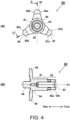
- FIG. 4(A) is a front view of the anvil 50.
- the anvil 50 has the same shape as the anvil 50 used in the conventional impact tool 1.
- the anvil 50 is attached in a position where the internal between the anvil 50 and the hammer 30 as viewed in the direction of the rotation axis A1 is slightly smaller than that in the conventional impact tool.
- the anvil 50 has the three blades 56 to 58.
- the struck surfaces 56a, 57a, and 58a are formed on one side of the blades 56 to 58 in the rotation direction, and the struck surfaces 56b, 57b, and 58b are formed on the other side.
- FIG. 4(B) is a sectional view of section B-B of FIG. 4(A) .
- the mounting hole 53 of the anvil 50 is configured to extend not only to the small diameter part 52 but also to the rear side in the direction of the rotation axis A1 until the inner side of the main shaft 51. By this configuration, it is possible to mount the tip tool (not shown) such as a bit in the axial direction.
- the through hole 52a is a hole penetrating to the outside from the mounting hole 53 inside the small diameter part 52.
- the through hole 52a is formed slightly larger than the steel ball 64 (see FIG. 1 ), and is formed in the following manner.
- a circumferentially continuous circumferential groove 52b is formed in order to fix a retaining ring 63 (see FIG. 1 ) that holds the spring 62 (see FIG. 1 ).
- the blades 56, 57, and 58 (57 is not visible in the drawing) extending radially outward from the flange 54 are formed, and the columnar shaft 55 is formed on the rear side of the blades 56, 57, and 58.
- the shaft 55 is formed solid and is axially supported in a slidable state by engaging with the fitting hole (see FIG. 1 ) of the spindle 26.
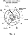
- FIG. 5 is a front view showing the hammer 30 and the anvil 50 in a normal striking state.
- a rotation center of each of the hammer 30 and the anvil 50 is coaxial with the rotation axis A1 that normally serves as a rotation center of the motor 3.
- a striking surface 36a of the hammer claw 36 and the struck surface 56a of the anvil 50 are in good surface contact over substantially the entire surface as shown by a portion indicated by a thick black line.
- a striking surface 37a of the hammer claw 37 and the struck surface 57a of the anvil 50 are in good surface contact over substantially the entire surface
- a striking surface 38a of the hammer claw 38 and the struck surface 58a of the anvil 50 are in good surface contact over substantially the entire surface. Since the surface contact occurs at the same time in these three places when the hammer 30 rotates during normal rotation, a striking force rotationally symmetrical with respect to the rotation axis A1 is transmitted from the hammer 30 to the anvil 50.
- FIG. 6 illustrates a longitudinal section for comparing the hammer 30 and the anvil 50 in terms of shape, in which the upper half above the rotation axis A1 illustrates the shape of the hammer 30 and the anvil 50 of the present invention, and the lower half illustrates the shape of conventional hammers 330 and 350.
- an outer wall surface (front facing surface 332) on the front side of a main body part 331 is a surface perpendicular to the rotation axis A1
- a flat surface 32b (orthogonal plane) orthogonal to the rotation axis A1 is defined from a radially inner position 32a to the boundary position 33, and the tapered surfaces 34a to 34c (portion of 34c is visible in the drawing) are defined on the outer peripheral side from the boundary position 33. Since the boundary position 33 is located inside an outermost diameter portion of the anvil 50, the outermost diameter portion of the anvil 50 is located to face the tapered surfaces 34a to 34c. As a result, a distance between a striking point 45 of the hammer claw 36 of the present embodiment and the main body part 31 (root position 46) of the hammer 30 is L4 as indicated in the drawing.
- a distance between a striking point 345 of a hammer claw 336 and the main body part 331 (root position 346) of the hammer 330 is L3 as indicated in the drawing, and a relationship of L4>L3 is established.
- an axial length D1 from the flat surface 32b (orthogonal plane) of the hammer 30 to a rear end can be configured to be greater than an axial length D2 from the tapered surfaces 34a to 34c of the hammer 30 to the rear end.
- the tapered surfaces 34a to 34c are formed on the outer peripheral side of the front wall surface of the main body part 31 of the hammer 30.
- the tapered surfaces 34a to 34c may be formed in a curved shape, a circular arc shape, or a polygonal shape instead of a sectional shape as in FIG. 6 that is a linear shape.
- FIG. 7(A) is a front view showing a striking state when the hammer 30 and the anvil 50 are misaligned.
- striking occurs at the same time between the striking surface 36a and the struck surface 56a, between the striking surface 37a and the struck surface 57a (not shown), and between the striking surface 38a and the struck surface 58a.
- point contact or line contact instead of surface contact may occur at the initial striking point between the hammer 30 and the anvil 50.
- the timing of striking may not be the same in the three places.
- FIG. 7(A) illustrates the deviation between the rotation centers A2 and A3 to be extremely large for describing the state. It should be noted that some of the blades of the anvil 50 have been omitted.
- FIG. 7(A) shows an example in which the initial striking point becomes a specific place (striking point shown in the drawing) in the hammer claw 36 and the blade 56 due to deviation of the rotation center A2 of the hammer 30.
- the rotation center A3 of the anvil 50 may deviate in an opposite direction with respect to the rotation axis A1.
- FIG. 7(B) shows a section of section C-C in this state.
- FIG. 7(B) is a sectional view of section C-C and a view in the direction of the rotation axis A1 from section C-C.
- the position of the blade 56 of the anvil 50 is indicated by a two-dot chain line.
- the hammer claw 36 is in contact with the blade 56 of the anvil 50 on the front side away from a chamfered groove 41a formed at the root of the hammer claw 36 in the direction of the rotation axis A1.
- the root of the hammer claw 36 and the blade 56 of the anvil 50 may become further away from each other in the direction of the rotation axis A1 than in the state of FIG. 1 due to a rotation speed of the spindle 26, a load acting on the tip tool or the like. That is, the striking point (line) shown in FIG. 7(A) may occur on the front side as viewed in the direction of the rotation axis A1.
- FIG. 8 is an enlarged view of part D of FIG. 7(B) .
- a claw for example, hammer claw 36
- a blade for example, blade 56
- the striking surface 36a of the hammer claw 36 is distorted from the position of the dot-and-dash line in a manner as shown by a striking surface 36a' indicated by a solid line (although the distortion is illustrated to be extremely large in FIG. 8 for ease of understanding, the actual distortion is very small) by an impact due to collision with the blade 56 of the anvil 50.
- a distance from the tapered surface 34c to a striking point as viewed in the direction of the rotation axis A1 is L4, like the hammer claw 36.
- the striking point is displaced by d from the position of the striking surface 36a when no striking occurs, and the striking surface 36a' of the hammer claw 36 is deformed by an angle ⁇ at the time of striking.
- the striking surface 36a of the hammer claw 36 and the struck surface 57a of the anvil 50 come into contact with each other over substantially the entire surface as shown in FIG. 5 .
- the position of the front facing surface 332 of the main body part of the hammer is a position indicated by a dotted line in FIG. 8 .
- a distance from the position of the dotted line to the striking point as viewed in the direction of the rotation axis A1 is L3.
- a striking surface of the hammer claw 336 is deformed by an angle ⁇ at the time of striking, and a relationship of ⁇ is established. That is, a stress generated in each of the hammer claws 36 to 38 is reduced in the shape in which the present invention is applied.
- a contact part of the hammer claw expands toward an inner diameter side before occurrence of a large stress at a root of the contact part, and a difference due to a position of a load borne by the root of the hammer claw can be reduced.
- stress concentration in the vicinity of the outer diameter side end of the claw root that occurs when the hammer claw makes partial contact can be reduced, and a striking mechanism having high reliability and excellent durability can be realized.
- FIG. 9 is a perspective view of a hammer 130 and an anvil 150 according to a second embodiment of the present invention.
- the hammer 130 is configured to include a main body part 131 and three hammer claws 136 to 138.
- a flat surface (front facing surface 132) orthogonal to the rotation axis A1 is defined from a radially inner position of the main body part 131 to a boundary position 133, and tapered surfaces 134a to 134c are defined on the outer peripheral side from the boundary position 133.
- Six grooves 141a, 141b (not visible in the drawing), 142a, 142b, 143a, and 143b are formed in the shape of the hammer 130. These grooves are formed to have a radius of curvature r.
- the radius of curvature r can be made smaller than that of a groove formed in the conventional hammer 330. While exaggerated in FIG. 9 for understanding the description, the radius of curvature r is actually a very small radius of about 1 mm.
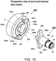
- FIG. 10 is a perspective view of a hammer 230 and an anvil 250 according to a third embodiment of the present invention.
- the number of hammer claws and blades is three.
- the present invention can be similarly realized by an impact tool in which the number of hammer claws of the hammer 230 is two and the number of blades of the anvil 250 is two, as in FIG. 10 .
- the hammer 230 is configured to include a main body part 231 and two hammer claws 236 and 237.
- a flat surface (front facing surface 232) orthogonal to the rotation axis A1 is defined from a radially inner position of the main body part 231 to a boundary position 233, and tapered surfaces 234a and 234b are defined on the outer peripheral side from the boundary position 233.
- the two hammer claws 236 and 237 are disposed 180 ° apart in the circumferential direction.
- the hammer claw 236 is substantially fan-shaped in section orthogonal to the rotation axis A1, and has a striking surface 236a during forward rotation and a striking surface 236b during reverse rotation formed on a side surface in the circumferential direction.
- joints 241a and 241b (241b is not visible in the drawing) formed by gently curved surfaces are formed.
- a joint 242a formed by a gently curved surface is formed.
- Chamfering 241c is applied to a corner between an outer peripheral surface and a front surface of the hammer claw 236, and chamfering 242c is applied to a corner between an outer peripheral surface and a front surface of the hammer claw 237.
- the anvil 250 two blades 256 and 257 are disposed 180 ° apart in the circumferential direction.
- the main shaft 51, the small diameter part 52, the mounting hole 53 and the shaft 55 of the anvil 250 have the same shape as those of the anvil 50 of the first embodiment.
- the shape of an outer half of the blades 256 and 257 as viewed in the radial direction is the same as an outer shape of the blades 56 to 58 of the anvil 50 shown in the first embodiment.
- a struck surface 256a during forward rotation and a struck surface 256b during reverse rotation are formed on a side surface of the blade 256.
- a struck surface 257a during forward rotation and a struck surface 257b during reverse rotation are formed on a side surface of the blade 257.
- the present invention can also be applied to an impact tool in which the number of hammer claws and blades is two.
- the present invention has been described above based on the embodiments. However, the present invention is not limited to the above embodiments, and various modifications can be made without departing from the spirit of the present invention.
- the shape of a hammer claw of a hammer or the shape of a blade of an anvil is not limited to the above examples, and the hammer claw and the blade may be realized in other shapes.
- an outer peripheral portion of a surface located on a front side of a main body part of the hammer may be formed to be tapered, and the hammer claw may be configured to have different lengths in the rotation axis direction on the inner peripheral side and on the outer peripheral side.
- a tapered surface may not be formed as a plane, and may be formed as a circular arc surface having an outwardly convex shape, or may have a polyhedral shape.
Landscapes
- Engineering & Computer Science (AREA)
- Mechanical Engineering (AREA)
- Percussive Tools And Related Accessories (AREA)
- Portable Power Tools In General (AREA)
Abstract
Description
- The present invention relates to an impact tool for fastening a fastener such as a screw or a bolt.
- As a striking tool for fastening a screw or the like, there has been known an impact tool in which a rotational striking mechanism is driven by a motor to rotate and strike an anvil, thereby intermittently transmitting a rotational striking force to a tip tool and performing an operation such as screw fastening. The impact tool includes the motor, a power transmission mechanism connected to the motor, and the tip tool connected to the power transmission mechanism. By an operator connecting the tip tool to a fastener such as a screw and rotating the motor, the impact tool fastens the fastener with impact. As such an impact tool, a technique of
Patent Document 1 has been known. InPatent Document 1, as a power transmission mechanism, a striking mechanism is provided that converts a rotational force into a striking force in a rotation direction. In the striking mechanism, an anvil that outputs the rotational force to the tip tool and a collision part (claw part) of a hammer that imparts the striking force to the anvil are each provided in three places. - Patent Document 1:
WO 2016/002539 - With the recent increase in the output of the impact tool, a power source such as a battery pack has been strengthened and motor performance has been improved. As a result, there is an increasing fear that a mechanical component such as the striking mechanism may be unable to withstand the output of the motor and may be damaged, and a good countermeasure is thus necessary. As the countermeasure against damage to the mechanical component, it is conceivable to change the material and shape of the hammer or the anvil or the like. For example, in the past there were two sets of a hammer claw and an anvil blade. In the technique of
Patent Document 1, the number of sets has been increased to three. By increasing the number of sets of hammer claws and anvil blades to three, contact at the time of striking is distributed in three places in a circumferential direction, and a force applied to each place of contact can therefore be reduced. However, on the other hand, in the case where all these places of contact are not able to undergo collision at the same time (for example, if contact occurs in two instead of three places at the same time, and occurs in the remaining one place after a slight delay), an extremely large stress occurs in the vicinity of an outer diameter side end of a root of a hammer claw. Countermeasures such as providing a groove having a large radius of curvature R at the root of the hammer claw or chamfering an end of the hammer claw have been taken. However, these countermeasures result in an increase in an overall length of a product or an increase in the number of processing steps in part processing. - The present invention has been made in view of the above background, and an object thereof is to provide an impact tool in which a stress generated in a joint between a main body part of a hammer and a striking claw is reduced. Another object of the present invention is to provide an impact tool with a reduced overall length and improved workability.
- Representative features of the invention disclosed herein will be described as follows. According to one feature of the present invention, an impact tool includes: a motor; a spindle, driven in a rotation direction by the motor; a hammer, relatively movable in an axial direction and a rotation direction within a predetermined range with respect to the spindle and energized forward by a cam mechanism and a spring; and an anvil, rotatably provided in front of the hammer and struck by the hammer when the hammer rotates while moving forward. In the impact tool, the hammer is configured to include a main body part and a claw part extending forward from the main body part, and a front inner diameter side end of the main body part is configured to be located in front of a front outer diameter side end of the main body part. The main body part of the hammer includes a front wall, and the claw part has a shape protruding from the front wall toward the anvil as viewed in a rotation axis direction. At this time, a relationship between a length L1 of an inner diameter side front end of the claw part from the main body part and a length L2 of an outer diameter side front end of the claw part from the main body part is configured to satisfy L1<L2.
- According to another feature of the present invention, the main body part of the hammer is formed with a tapered surface that gradually recedes away from a rotation axis. By configuring a portion or the whole of the claw part to protrude from the tapered surface toward the anvil in this way, the relationship of L1<L2 can be realized. A groove having a predetermined rotation radius R is formed in a connection corner on both circumferential sides of the main body part and the claw part of the hammer.
- According to yet another feature of the present invention, an orthogonal plane orthogonal to the rotation axis is configured to be formed in the main body part of the hammer, and an axial length D1 of the hammer from the orthogonal plane to a rear end is configured to be greater than an axial length D2 of the hammer from the tapered surface to the rear end. By providing the tapered surface on an outer peripheral side of a front side surface of the hammer excluding the hammer claw part, a configuration satisfying D1>D2 is realized.
- According to yet another feature of the present invention, a spring support for supporting the spring is configured to be formed on a side of the main body part of the hammer opposite the anvil, and the tapered surface is configured to extend from radially outside of a radial center position of the spring support. The cam mechanism is configured to include a spindle cam groove provided on the spindle, a hammer cam groove formed on an inner peripheral side of the hammer, a cam ball disposed between the spindle cam groove and the hammer cam groove, and a spring having a coil shape that is disposed around the spindle and energizes the hammer toward the anvil in a rotation axis direction. The motor of the impact tool is driven using a battery that is able to be used in a detachable electric tool as a driving power source.
- According to the impact tool of the present invention, stress concentration in the vicinity of an outer diameter side end of a root of a hammer claw can be reduced. A striking mechanism can be made compact.
-
-
FIG. 1 is a longitudinal sectional view showing an overall structure of animpact tool 1 of the present embodiment. -
FIG. 2 is a perspective view of ahammer 30 and ananvil 50 ofFIG. 1 . -
FIG. 3 illustrates thehammer 30 ofFIG. 2 , in which (A) is a front view and (B) is a longitudinal sectional view. -
FIG. 4 illustrates theanvil 50 ofFIG. 2 , in which (A) is a front view and (B) is a longitudinal sectional view. -
FIG. 5 is a front view showing thehammer 30 and theanvil 50 ofFIG. 1 in a normal striking state. -
FIG. 6 illustrates a longitudinal section for comparing thehammer 30 and theanvil 50 of the present embodiment and aconventional hammer 330 and aconventional anvil 350 in terms of shape, in which the upper half above a rotation axis A1 shows the shape of the present embodiment, and the lower half shows the conventional shape. - (A) of
FIG. 7 is a front view showing a striking state when thehammer 30 and theanvil 50 are misaligned, and (B) ofFIG. 7 is a sectional view of section C-C and a view in a direction of the rotation axis A1 from section C-C. -
FIG. 8 is a partially enlarged view of part D ofFIG. 7(B) . -
FIG. 9 is a perspective view of ahammer 130 and an anvil 150 according to a second embodiment of the present invention. -
FIG. 10 is a perspective view of ahammer 230 and ananvil 250 according to a third embodiment of the present invention. - Hereinafter, an embodiment of the present invention is described based on the drawings. In the following description, the front-rear, left-right, and up-down directions are described as the directions shown in the drawings.
-
FIG. 1 is a side view showing an appearance of animpact tool 1 according to an embodiment of the present invention. In theimpact tool 1, abattery 90 of a rechargeable pack type is used as a power source, a rotational force and a striking force are imparted to an output shaft (anvil 50) with a motor as a driving source, a rotational striking force is intermittently transmitted to a tip tool (not shown) such as a driver bit held in amounting hole 53 by amounting mechanism 60, and an operation such as screw fastening or bolt fastening is performed. Ahousing 2 of theimpact tool 1 is formed in a substantially T-shape, including atubular body 2a and ahandle 2b, thebody 2a having a substantially cylindrical shape for housing a motor and a power transmission mechanism, thehandle 2b extending from the vicinity of a substantial center of thebody 2a in a direction substantially orthogonal to a rotation axis A1 and being provided for an operator to grip with one hand. Among ends of thehandle 2b, a lower end (end on a side opposite the body) located on a side opposite thebody 2a has abattery attachment part 2c formed thereat. Atrigger lever 7a is disposed in an upper part inside thehandle 2b so as to protrude forward. A forward/reverse switching lever 8 for switching a rotation direction of amotor 3 between the forward direction and the reverse direction is provided on a rear side of thetrigger lever 7a. - The
motor 3 is housed on the rear side of thetubular body 2a. Themotor 3 is a DC (direct current) motor without a brush (rectifying brush), and is a 4-pole, 6-slot brushless DC motor. Themotor 3 includes arotor 3a including a permanent magnet and astator 3b including a multi-phase armature winding (stator winding) such as a three-phase winding. Therotor 3a forms a magnetic path formed by the permanent magnet. Thestator 3b is manufactured of a laminated structure of annular thin iron plates, and has six teeth (not shown) formed on the inner peripheral side thereof. An enameled wire is wound around each tooth to form a coil. In the present embodiment, the coil has a star connection or delta connection having three phases, namely, U phase, V phase, and W phase. Themotor 3 is operated in the following manner. That is, a DC voltage supplied from a battery or the like is switched by a plurality ofsemiconductor switching elements 14 using an output of aposition detector 13 composed of a plurality of Hall ICs that detect a magnetic force of the permanent magnet of therotor 3a and detect a rotor position. Although the motor is a brushless motor in the present embodiment, the motor may also be a brushed motor. - A rotation shaft 4 of the
motor 3 is disposed concentrically with the rotation axis A1 of thetubular body 2a, and axially supported by thehousing 2 by twobearings inverter circuit board 12 for mounting threeposition detectors 13 and sixsemiconductor switching elements 14 or the like is disposed on the rear side of thestator 3b. Theinverter circuit board 12 is a substantially annular double-sided board having approximately the same diameter as an outer diameter of themotor 3. Sixsemiconductor switching elements 14 are provided to form an inverter circuit and switch energization to the stator winding of each phase. As thesemiconductor switching element 14, a field-effect transistor (FET), an insulated gate bipolar transistor (IGBT) or the like may be used. Since the inverter circuit is controlled by a microcomputer and an energization timing of the armature winding of each phase is set based on a position detection signal for therotor 3a by theposition detector 13, advanced rotation control becomes easy. - A cooling
fan 15 is attached coaxially with the rotation shaft 4 between therotor 3a and thebearing 16b. The coolingfan 15 is, for example, integrally molded by a plastic mold, sucks air from an air intake (not shown) formed in the vicinity of both left and right sides of theinverter circuit board 12 of thebody 2a, and discharges the air rearward in the direction of the rotation axis A1 so that the air flows inside and around themotor 3. Cooling air that has passed through theinverter circuit board 12 cools themotor 3 located on the rear side of theinverter circuit board 12, and is discharged to the outside through an air discharge slit (not shown) formed on a side of the coolingfan 15. - A hammer case 5 formed in a cup shape is provided on the front side of the
housing 2. The hammer case 5 houses adecelerator 20 and an impact mechanism (striking mechanism) 25 therein and is provided on the front side of thebody 2a of thehousing 2. The hammer case 5 is made of an integral piece of metal, in which a throughhole 5a for theanvil 50 to penetrate therethrough is formed in a front portion corresponding to a bottom of the cup shape. A mountingmechanism 60 for enabling mounting or removal of the tip tool (not shown) is provided at a tip portion of theanvil 50 outside the hammer case 5. - The mounting
mechanism 60 is configured to include a mountinghole 53 having a hexagonal sectional shape and extending axially rearward from a front end of theanvil 50, two holes penetrating in a radial direction and formed in two places in a circumferential direction for disposing asteel ball 64, and asleeve 61 provided on an outer peripheral side. Aspring 62 that energizes thesleeve 61 rearward is mounted inside thesleeve 61. An illumination device 9 for irradiating the vicinity of a tip of the tip tool (not shown) is provided on a lower side of the mountingmechanism 60. One or a plurality of light-emitting diodes (LEDs) are used as the illumination device 9, and an irradiation window through which light is transmitted is provided on the front side of the illumination device 9. - The
trigger lever 7a is disposed so as to protrude forward in the upper part inside thehandle 2b extending integrally at a substantially right angle from thebody 2a of thehousing 2, and a trigger switch 7 is provided behind thetrigger lever 7a. By gripping thehandle 2b with one hand and pulling thetrigger lever 7a rearward with the index finger or the like, a user is able to adjust a trigger pushing amount (operation amount) and adjust a rotation speed of themotor 3. A rotation direction of themotor 3 can be switched by operating the forward/reverse switching lever 8. - The
battery attachment part 2c expanding in a direction substantially orthogonal to an axis direction of thehandle 2b is provided in a lower part inside thehandle 2b. Thebattery 90 serving as a driving power source for themotor 3 is detachably mounted on thebattery attachment part 2c. To remove thebattery 90, thebattery 90 is relatively moved forward from a main body part of theimpact tool 1 while alatch 91 is pressed. Acontrol circuit board 70 for controlling theinverter circuit board 12 of themotor 3 is provided in an upper part of thebattery 90. Thecontrol circuit board 70 is disposed horizontally so as to extend in the front-rear and left-right directions, and is equipped with a microcomputer (not shown) that controls rotation of themotor 3. Thecontrol circuit board 70 is connected to theinverter circuit board 12 via a signal line. In the vicinity of thecontrol circuit board 70, aswitch panel 75 for disposing a remaining capacity check switch and an LED display device for displaying the remaining capacity of thebattery 90 and a lighting switch of the illumination device 9 is provided on an upper surface of thebattery attachment part 2c. - The
body 2a of thehousing 2 is manufactured by integral molding of a synthetic resin material together with thehandle 2b and thebattery attachment part 2c, and is formed so that it can be divided into two in the left-right direction by a vertical plane passing through the rotation shaft 4 of themotor 3. At the time of assembly, the following method is employed. That is, members on the left side and members on the right side of thehousing 2 are prepared. The hammer case 5 having thedecelerator 20 and theimpact mechanism 25 incorporated therein and themotor 3 and the like are incorporated into thehousing 2 on one side (for example, the housing on the left side) as shown in the sectional view ofFIG. 1 in advance. Thereafter, thehousing 2 on one side is overlapped with thehousing 2 on the other side (for example, the housing on the right side) and is fastened with a plurality of screws. - The
impact mechanism 25 is provided on an output side of thedecelerator 20 composed of a planetary gear, includes aspindle 26 and ahammer 30, and is rotatably held by the bearing 18b at a rear end and by thebearing 18a at a front end. Thedecelerator 20 is configured to include asun gear 21 fixed to a tip of the rotation shaft 4 of themotor 3, aring gear 23 provided on an outer peripheral side of thesun gear 21 so as to surround thesun gear 21 with a distance therebetween, and a plurality ofplanetary gears 22 disposed in a space between thesun gear 21 and thering gear 23 and meshed with both gears. Thering gear 23 is also called an outer gear, in which a gear is formed on an inner peripheral surface of a ring-shaped member. An outer peripheral surface of thering gear 23 is held by thehousing 2, and thering gear 23 itself does not rotate. - The
sun gear 21 is a spur gear serving as an input part of thedecelerator 20. A plurality of (here, three)planetary gears 22 are disposed between an outer gear surface of thesun gear 21 and an inner gear surface of thering gear 23. The threeplanetary gears 22 are axially supported by a planetary carrier formed at a rear end of thespindle 26, and theplanetary gears 22 revolve around thesun gear 21 while rotating around a shaft (not shown) axially supported by the planetary carrier. When the rotation shaft 4 of themotor 3 rotates, thesun gear 21 also rotates synchronously therewith. A rotational force of thesun gear 21 is decelerated at a predetermined rate and thespindle 26 rotates. - An
inner cover 19 is a part manufactured by integral molding of synthetic resin, and is held by thebody 2a of thehousing 2 so as to be sandwiched from the left and right. At this time, theinner cover 19 is held so as not to relatively rotate with respect to thehousing 2. Since one of a plurality of screw bosses provided is located in an upper part of theinner cover 19, theinner cover 19 is stably sandwiched by thehousing 2. Theinner cover 19 mainly serves to hold the twobearings 18b and twobearings 16a provided and center the rotation shaft 4 of themotor 3 and a rotation center of thespindle 26 on the same axis. Thebearing 16a held by theinner cover 19 is for axially supporting the rotation shaft 4 of themotor 3, and a ball bearing, for example, may be used. Thebearing 18b held by theinner cover 19 is for axially supporting the rear end of thespindle 26, and a ball bearing, for example, may be used. - The
decelerator 20 and theimpact mechanism 25 constitute a power transmission mechanism for driving the tip tool by themotor 3. When thetrigger lever 7a is pulled and themotor 3 is activated, themotor 3 starts to rotate in a direction set by the forward/reverse switching lever 8 and a rotational force thereof is decelerated by thedecelerator 20 and transmitted to thespindle 26, and thespindle 26 rotates at a predetermined speed. Here, thespindle 26 and thehammer 30 are connected by a cam mechanism. This cam mechanism is composed of a V-shapedspindle cam groove 26a formed on an outer peripheral surface of thespindle 26, ahammer cam groove 39 formed on an inner peripheral surface of thehammer 30, and twosteel balls 27 engaging with thecam grooves hammer 30 is always energized forward by ahammer spring 28. In three places on rotation planes of thehammer 30 and theanvil 50 that face each other, hammer claws (striking claws) 36 to 38 (37 is not visible in the drawing) protruding convexly in the direction of the rotation axis A1 and blades (struck claws) 56 to 58 (only 56 is visible in the drawing) to be struck by the striking claws are formed rotationally symmetrical. - When the
spindle 26 is rotationally driven, rotation thereof is transmitted to thehammer 30 via the cam mechanism, and the striking claw of thehammer 30 engages with the struck claw of theanvil 50 to rotate theanvil 50 before thehammer 30 makes a half rotation. When relative rotation occurs between thespindle 26 and thehammer 30 due to an engagement reaction force between thehammer 30 and theanvil 50 during rotation, thehammer 30 starts to recede toward themotor 3 side while compressing thehammer spring 28 along thespindle cam groove 26a of the cam mechanism. When the striking claw of thehammer 30 rides across the struck claw of theanvil 50 due to the receding movement of thehammer 30 and the engagement between the two is released, while rapidly accelerated in a rotation direction and forward by elastic energy accumulated in thehammer spring 28 and the action of the cam mechanism in addition to a rotational force of thespindle 26, thehammer 30 is moved forward by an energization force of thehammer spring 28, and the striking claw (such as 36) of thehammer 30 engages again with the struck claw (such as 56) of theanvil 50 and they start to rotate together. When thehammer 30 makes one relative rotation with respect to theanvil 50, the number of striking (simultaneous striking) becomes 3 (low speed striking) or 1.5 (high speed striking). Since a strong rotational striking force is applied to theanvil 50 in this way, the rotational striking force is transmitted to the tip tool (not shown) mounted in the mountinghole 53 integrally formed with theanvil 50. Afterward, the same operation is repeated, the rotational striking force is intermittently and repeatedly transmitted to the tip tool, and a wood screw, for example, is screwed into a fastened member (not shown) such as a piece of wood. -
FIG. 2 is a perspective view of thehammer 30 and theanvil 50 according to the present embodiment. Thehammer 30 is disposed between the decelerator 20 and theanvil 50 in the direction along the rotation axis A1. Thehammer 30 is configured to be relatively rotatable with respect to the spindle 26 (seeFIG. 1 ) and relatively movable in the direction along the rotation axis A1.Hammer cam grooves hammer 30. The steel ball 27 (seeFIG. 1 ) is disposed inside thehammer cam grooves hammer 30 is held on the spindle 26 (seeFIG. 1 ) via the steel ball 27 (seeFIG. 1 ), thehammer 30 is movable in the direction along the rotation axis A1 within a range in which thesteel ball 27 is rollable, and thehammer 30 is relatively rotatable with respect to thespindle 26 within a predetermined range in a circumferential direction about the rotation axis A1 as a central axis within the range in which thesteel ball 27 is rollable. - When a load in a rotation direction of the
anvil 50 increases, thehammer claws 36 to 38 of thehammer 30 and theblades 56 to 58 of theanvil 50 are repeatedly engaged and disengaged, thereby generating a rotational striking force on theanvil 50 serving as the output shaft. Here, the weight of thehammer 30 is set greater than the weight of theanvil 50. Thehammer 30 converts the rotational force of thespindle 26 into the rotational force of theanvil 50 or the striking force in the rotation direction. - The
hammer 30 is composed of amain body part 31 formed in a substantially cylindrical shape and thehammer claws 36 to 38 extending forward from themain body part 31. In the present specification, a portion of thehammer 30 other than thehammer claws 36 to 38 is defined as the "main body part 31". On theanvil 50 side of themain body part 31, a front facing surface 32 (orthogonal plane) orthogonal to the rotation axis A1 is formed. Thefront facing surface 32 is a surface adjacent to and facing theanvil 50, and faces with a slight gap with respect to, or contacts, theblades 56 to 58 of theanvil 50 when thehammer 30 is in a normal position (front position within a forward and rearward movement range along the rotation axis A1). Thefront facing surface 32 is a substantially annular surface orthogonal to the rotation axis A1.Tapered surfaces 34a to 34c are formed on an outer peripheral side of thefront facing surface 32. The tapered surfaces 34a to 34c are inclined surfaces that are inclined rearward (toward the side opposite the anvil) in the direction of the rotation axis A1 as going from a radially inner peripheral side to the outer peripheral side. InFIG. 2 , a joint between an outer peripheral edge of thefront facing surface 32 and an inner peripheral edge of thetapered surfaces 34a to 34c is illustrated as double lines. This is because an area between the double lines is formed as a surface having a small radius of curvature due to the fact that a sectional shape of the joint that includes the rotation axis A1 is chamfered. Whether to set the outer peripheral edge of thefront facing surface 32 and the inner peripheral edge of thetapered surfaces 34a to 34c to be angular, or whether to connect the double lines by a plane, or whether to form a groove recessed inward in a plane direction between the double lines is arbitrary. - The
hammer claws 36 to 38 are formed to protrude forward from themain body part 31 and are integrally formed with themain body part 31. Circumferential center positions of thehammer claws 36 to 38 are disposed at intervals (equal intervals) of 120 degrees in the circumferential direction, and thehammer claws 36 to 38 are substantially fan-shaped in section along a direction intersecting the rotation axis A1. A width dimension of thehammer claws 36 to 38 radially outside thehammer 30 and in a direction along the circumferential direction is set to about 10 mm. Accordingly, sufficient strength of thehammer claws 36 to 38 is secured, and thehammer claws 36 to 38 adjacent to each other along the circumferential direction of thehammer 30 allow theblades 56 to 58 of theanvil 50 to easily enter therebetween. A central angle portion of the substantially fan shape is located on a side close to the rotation axis A1, and a circular arc portion is located in approximately the same position as or slightly inside an outer edge of themain body part 31 of thehammer 30. A circular arc portion of the sectional shape of thehammer claws 36 to 38 may be in a shape whose diameter is the same or slightly decreases from the rear toward the front in the direction of the rotation axis A1. In the present embodiment, an outer peripheral surface of each of thehammer claws 36 to 38 has a shape in which an outer diameter on a tip side is slightly reduced so that the diameter of the outer peripheral surface slightly decreases toward the front. A front end face of each of thehammer claws 36 to 38 is chamfered so as to be orthogonal to the rotation axis A1. That is, the front end face of thehammer claws 36 to 38 is a surface parallel to thefront facing surface 32. - The tapered surfaces 34a to 34c are disposed so as to be circumferentially interrupted by the three
hammer claws 36 to 38 as viewed in the circumferential direction. An innermost peripheral position of each of thetapered surfaces 34a to 34c is disposed between a radially innermost position and a radially outermost position of the substantially fan-shapedhammer claws 36 to 38. By setting aboundary position 33 between thetapered surfaces 34a to 34c and thefront facing surface 32, a protrusion amount (size indicated by L1 inFIG. 3 described later) of thehammer claws 36 to 38 toward the front along the rotation axis A1 with respect to themain body part 31 in an innermost peripheral position and a protrusion amount (size indicated by L2 inFIG. 3 described later) in an outermost peripheral position can be formed different from each other. - The
anvil 50 is manufactured by integral molding of metal, and has the threeblades 56 to 58 formed protruding radially outward from anannular flange 54 on the rear side of amain shaft 51. Themain shaft 51 is a portion axially supported by thebearing 18a (seeFIG. 1 ) using a needle bearing, and serves as a rolling surface of a needle of thebearing 18a. On the front side of themain shaft 51, asmall diameter part 52 is formed slightly narrow for attaching the mountingmechanism 60 of the tip tool (not shown). The mountinghole 53 for mounting the tip tool that has a hexagonal sectional shape is formed from a tip of thesmall diameter part 52 rearward in the direction of the rotation axis A1. In the vicinity of a rear end of thesmall diameter part 52, two throughholes 52a are formed penetrating in the radial direction, and the steel ball 64 (seeFIG. 1 ) that is a component of the mountingmechanism 60 is disposed. Between (portion of arrow 61c) the throughhole 52a and theblades 56 to 58 as viewed in the axial direction is themain shaft 51 whose outer peripheral surface is formed columnar. - The three
blades 56 to 58 serving as a struck part are struck claws that are evenly disposed so that their circumferential center positions are separated at intervals of 120 ° as viewed in the rotation direction, and are disposed so as to extend radially outward. On a side surface of theblades 56 to 58 in the rotation direction, strucksurfaces hammer 30 during rotation in a fastening direction and strucksurfaces struck surfaces columnar shaft 55 is formed on the rear side of theblades 56 to 58, and an outer peripheral surface of theshaft 55 is axially supported in a slidable state by engaging with a fitting hole (seeFIG. 1 ) of thespindle 26. A width dimension of theblades 56 to 58 radially outside theanvil 50 and in the direction along the circumferential direction is set to about 5 mm. That is, the width dimension of theblades 56 to 58 is set slightly shorter than that of thehammer claws 36 to 38. Accordingly, sufficient strength of theblades 56 to 58 is secured, and theblades 56 to 58 adjacent to each other along the circumferential direction of theanvil 50 have a relatively long distance therebetween and allow thehammer claws 36 to 38 of thehammer 30 to easily enter therebetween. -
FIG. 3(A) is a front view of thehammer 30, and the longitudinal sectional view of (B) is a sectional view of section A-A of (A). Since only one of the threehammer claws 36 to 38 is shown in a vertical sectional view inFIG. 3(B), FIG. 3(B) is taken as a sectional view of section A-A (inFIG. 1 andFIG. 6 , the position of the section of thehammer 30 and theanvil 50 is set as a section like section A-A). InFIG. 3(A) , a front wall surface of themain body part 31 of thehammer 30 is formed by thefront facing surface 32 located on the inner peripheral side and thetapered surfaces hammer claws front facing surface 32, and is an area where the outer peripheral side is joined to thetapered surfaces boundary position 33 between thetapered surfaces front facing surface 32 is preferably configured to be located between an innermost position and an outermost position of the fan-shaped portion of thehammer claws - In
FIG. 3(B) , thehammer 30 has a double tubular shape composed of anouter tube 31a and aninner tube 31c, and theouter tube 31a and theinner tube 31c are connected on the front side thereof by a frontsurface connection part 31b. Thefront facing surface 32 and thetapered surfaces 34a to 34c are formed on the front side of the frontsurface connection part 31b. Aspring support 31d for supporting a front end of a coil-shaped spring on which thehammer spring 28 is held is formed on the rear side of the frontsurface connection part 3 1b. A center position (frontmost position) of an annular shape of thespring support 31d and theboundary position 33 between thetapered surfaces 34a to 34c and the orthogonal plane (front facing surface 32) have such a positional relationship that their distance from the rotation axis A1 is approximately the same. By forming thehammer 30 as described above, a length of thehammer claws tapered surfaces -
FIG. 4(A) is a front view of theanvil 50. Theanvil 50 has the same shape as theanvil 50 used in theconventional impact tool 1. Theanvil 50 is attached in a position where the internal between theanvil 50 and thehammer 30 as viewed in the direction of the rotation axis A1 is slightly smaller than that in the conventional impact tool. Theanvil 50 has the threeblades 56 to 58. The struck surfaces 56a, 57a, and 58a are formed on one side of theblades 56 to 58 in the rotation direction, and thestruck surfaces hammer 30 is applied to theanvil 50, by forming theannular flange 54 on the outer peripheral side of themain shaft 51 and rendering theflange 54 and theblades 56 to 58 to be nearly triangular as viewed from the front, strength is improved. -
FIG. 4(B) is a sectional view of section B-B ofFIG. 4(A) . The mountinghole 53 of theanvil 50 is configured to extend not only to thesmall diameter part 52 but also to the rear side in the direction of the rotation axis A1 until the inner side of themain shaft 51. By this configuration, it is possible to mount the tip tool (not shown) such as a bit in the axial direction. The throughhole 52a is a hole penetrating to the outside from the mountinghole 53 inside thesmall diameter part 52. The throughhole 52a is formed slightly larger than the steel ball 64 (seeFIG. 1 ), and is formed in the following manner. That is, by forming only the diameter of the throughhole 52a at the innermost position to be slightly smaller than thesteel ball 64, thesteel ball 64 inserted from the outer peripheral side of the throughhole 52a remains on the mountinghole 53 side with a certain amount of protrusion without being able to pass through the inside of the mountinghole 53 on the radially inner side. In the vicinity of the tip of thesmall diameter part 52 in the direction of the rotation axis A1, a circumferentially continuouscircumferential groove 52b is formed in order to fix a retaining ring 63 (seeFIG. 1 ) that holds the spring 62 (seeFIG. 1 ). On the rear side of themain shaft 51, theblades flange 54 are formed, and thecolumnar shaft 55 is formed on the rear side of theblades shaft 55 is formed solid and is axially supported in a slidable state by engaging with the fitting hole (seeFIG. 1 ) of thespindle 26. -
FIG. 5 is a front view showing thehammer 30 and theanvil 50 in a normal striking state. A rotation center of each of thehammer 30 and theanvil 50 is coaxial with the rotation axis A1 that normally serves as a rotation center of themotor 3. In this coaxial state, astriking surface 36a of thehammer claw 36 and thestruck surface 56a of theanvil 50 are in good surface contact over substantially the entire surface as shown by a portion indicated by a thick black line. Similarly, astriking surface 37a of thehammer claw 37 and thestruck surface 57a of theanvil 50 are in good surface contact over substantially the entire surface, and astriking surface 38a of thehammer claw 38 and thestruck surface 58a of theanvil 50 are in good surface contact over substantially the entire surface. Since the surface contact occurs at the same time in these three places when thehammer 30 rotates during normal rotation, a striking force rotationally symmetrical with respect to the rotation axis A1 is transmitted from thehammer 30 to theanvil 50. -
FIG. 6 illustrates a longitudinal section for comparing thehammer 30 and theanvil 50 in terms of shape, in which the upper half above the rotation axis A1 illustrates the shape of thehammer 30 and theanvil 50 of the present invention, and the lower half illustrates the shape ofconventional hammers conventional hammer 330, an outer wall surface (front facing surface 332) on the front side of a main body part 331 is a surface perpendicular to the rotation axis A1, is a flat surface from a radiallyinner position 332a to a radiallyouter position 332b of thefront facing surface 332, and is in the same position in the direction of the rotation axis A1. On the other hand, in thehammer 30 of the present embodiment, aflat surface 32b (orthogonal plane) orthogonal to the rotation axis A1 is defined from a radiallyinner position 32a to theboundary position 33, and thetapered surfaces 34a to 34c (portion of 34c is visible in the drawing) are defined on the outer peripheral side from theboundary position 33. Since theboundary position 33 is located inside an outermost diameter portion of theanvil 50, the outermost diameter portion of theanvil 50 is located to face thetapered surfaces 34a to 34c. As a result, a distance between astriking point 45 of thehammer claw 36 of the present embodiment and the main body part 31 (root position 46) of thehammer 30 is L4 as indicated in the drawing. On the other hand, in theconventional hammer 330, a distance between astriking point 345 of ahammer claw 336 and the main body part 331 (root position 346) of thehammer 330 is L3 as indicated in the drawing, and a relationship of L4>L3 is established. By setting L4>L3 in this way, thehammer claws 36 to 38 become more likely to deform as approaching an outer diameter side end. Even if thehammer claws 36 to 38 and theblades 56 to 58 of theanvil 50 locally contact at the outer diameter side end, since a contact part of thehammer claws 36 to 38 expands toward an inner diameter side before occurrence of a large stress in the vicinity of a root of the contact part, a difference due to a position of a load borne by the vicinity of the root is reduced. As a result, stress concentration in a specific portion (the vicinity of the outer diameter side end of a claw root) that occurs when thehammer claws 36 to 38 make partial contact is reduced. - In the present embodiment, since the
flat surface 32b (orthogonal plane) and thetapered surfaces 34a to 34c are provided on the front side of themain body part 31 of thehammer 30, an axial length D1 from theflat surface 32b (orthogonal plane) of thehammer 30 to a rear end can be configured to be greater than an axial length D2 from the taperedsurfaces 34a to 34c of thehammer 30 to the rear end. The tapered surfaces 34a to 34c are formed on the outer peripheral side of the front wall surface of themain body part 31 of thehammer 30. The tapered surfaces 34a to 34c may be formed in a curved shape, a circular arc shape, or a polygonal shape instead of a sectional shape as inFIG. 6 that is a linear shape. -
FIG. 7(A) is a front view showing a striking state when thehammer 30 and theanvil 50 are misaligned. During the normal rotation shown inFIG. 5 (when the rotation centers of thehammer 30 and theanvil 50 match), striking occurs at the same time between thestriking surface 36a and thestruck surface 56a, between thestriking surface 37a and thestruck surface 57a (not shown), and between thestriking surface 38a and thestruck surface 58a. However, when the rotation center of thehammer 30 deviates from a rotation center A3 of theanvil 50 like A2, point contact (or line contact) instead of surface contact may occur at the initial striking point between thehammer 30 and theanvil 50. Moreover, the timing of striking may not be the same in the three places.FIG. 7(A) illustrates the deviation between the rotation centers A2 and A3 to be extremely large for describing the state. It should be noted that some of the blades of theanvil 50 have been omitted. -
FIG. 7(A) shows an example in which the initial striking point becomes a specific place (striking point shown in the drawing) in thehammer claw 36 and theblade 56 due to deviation of the rotation center A2 of thehammer 30. Not only the position of the rotation center A2 of thehammer 30 deviates with respect to the rotation axis A1, but the rotation center A3 of theanvil 50 may deviate in an opposite direction with respect to the rotation axis A1. When the rotation centers A2 and A3 deviate in opposite directions in this way, a state as inFIG. 7(A) is achieved (the deviation is greatly exaggerated for convenience of description). At this time, while striking has occurred between thehammer claw 36 and theblade 56 and between thehammer claw 38 and theblade 58, striking has not occurred between thehammer claw 37 and the blade 57 (not shown). When the rotation center A2 of thehammer 30 deviates, the initial striking point is located inside anoutermost position 36c of thehammer claw 36. In contrast, in thehammer claw 38, a striking point to theblade 58 is in the vicinity of anoutermost position 38c.FIG. 7(B) shows a section of section C-C in this state. -
FIG. 7(B) is a sectional view of section C-C and a view in the direction of the rotation axis A1 from section C-C. Here, the position of theblade 56 of theanvil 50 is indicated by a two-dot chain line. In this drawing, thehammer claw 36 is in contact with theblade 56 of theanvil 50 on the front side away from a chamferedgroove 41a formed at the root of thehammer claw 36 in the direction of the rotation axis A1. In a striking operation during use, the root of thehammer claw 36 and theblade 56 of theanvil 50 may become further away from each other in the direction of the rotation axis A1 than in the state ofFIG. 1 due to a rotation speed of thespindle 26, a load acting on the tip tool or the like. That is, the striking point (line) shown inFIG. 7(A) may occur on the front side as viewed in the direction of the rotation axis A1. -
FIG. 8 is an enlarged view of part D ofFIG. 7(B) . When thehammer 30 rotates in a direction of a black arrow while advancing in the direction of the rotation axis A1 after thehammer spring 28 is compressed, a claw (for example, hammer claw 36) of thehammer 30 strikes a blade (for example, blade 56) of theanvil 50.FIG. 8 shows a state immediately after striking. From a normal state (parallel to the rotation axis A1) indicated by a dot-and-dash line, thestriking surface 36a of thehammer claw 36 is distorted from the position of the dot-and-dash line in a manner as shown by astriking surface 36a' indicated by a solid line (although the distortion is illustrated to be extremely large inFIG. 8 for ease of understanding, the actual distortion is very small) by an impact due to collision with theblade 56 of theanvil 50. At this time, in theimpact tool 1 of the present embodiment, a distance from the taperedsurface 34c to a striking point as viewed in the direction of the rotation axis A1 is L4, like thehammer claw 36. The striking point is displaced by d from the position of thestriking surface 36a when no striking occurs, and thestriking surface 36a' of thehammer claw 36 is deformed by an angle α at the time of striking. When the striking point is displaced by d, thestriking surface 36a of thehammer claw 36 and thestruck surface 57a of theanvil 50 come into contact with each other over substantially the entire surface as shown inFIG. 5 . In theconventional hammer 330 as shown in the lower half ofFIG. 6 , since no tapered surface is formed on the hammer, the position of thefront facing surface 332 of the main body part of the hammer is a position indicated by a dotted line inFIG. 8 . A distance from the position of the dotted line to the striking point as viewed in the direction of the rotation axis A1 is L3. In this case, a striking surface of thehammer claw 336 is deformed by an angle β at the time of striking, and a relationship of α<β is established. That is, a stress generated in each of thehammer claws 36 to 38 is reduced in the shape in which the present invention is applied. - As described above, by using the
hammer 30 of the present embodiment, even if a hammer claw and an anvil blade locally contact at an outer diameter side end, a contact part of the hammer claw expands toward an inner diameter side before occurrence of a large stress at a root of the contact part, and a difference due to a position of a load borne by the root of the hammer claw can be reduced. As a result, stress concentration in the vicinity of the outer diameter side end of the claw root that occurs when the hammer claw makes partial contact can be reduced, and a striking mechanism having high reliability and excellent durability can be realized. -
FIG. 9 is a perspective view of ahammer 130 and an anvil 150 according to a second embodiment of the present invention. Thehammer 130 is configured to include a main body part 131 and threehammer claws 136 to 138. A flat surface (front facing surface 132) orthogonal to the rotation axis A1 is defined from a radially inner position of the main body part 131 to aboundary position 133, and taperedsurfaces 134a to 134c are defined on the outer peripheral side from theboundary position 133. Sixgrooves 141a, 141b (not visible in the drawing), 142a, 142b, 143a, and 143b are formed in the shape of thehammer 130. These grooves are formed to have a radius of curvature r. By combination with thetapered surfaces conventional hammer 330. While exaggerated inFIG. 9 for understanding the description, the radius of curvature r is actually a very small radius of about 1 mm. By making the radius of curvature r of thegrooves 141a, 141b (not visible in the drawing), 142a, 142b, 143a, and 143b smaller than a radius of curvature r1 (not shown) in a hammer with a conventional groove formed therein, an interval (gap corresponding to L3 ofFIG. 6 ) between thehammer 130 and the anvil 150 in the direction of the rotation axis A1 can be made smaller than conventionally. In the case of a large radius of curvature r1 as conventionally, since a contact portion between thehammer 130 and the anvil 150 overlaps the groove portion, a length of a hammer claw of thehammer 330 in the direction of the rotation axis A1 is configured to be long, and an interval between thehammer 330 and theanvil 350 is widened. In theimpact tool 1 of the present embodiment, since the interval between thehammer 130 and the anvil 150 is made smaller than conventionally, the size of theimpact tool 1 can be made smaller than conventionally. -
FIG. 10 is a perspective view of ahammer 230 and ananvil 250 according to a third embodiment of the present invention. In the first embodiment and the second embodiment described above, an example has been given where the number of hammer claws and blades is three. However, the present invention can be similarly realized by an impact tool in which the number of hammer claws of thehammer 230 is two and the number of blades of theanvil 250 is two, as inFIG. 10 . Thehammer 230 is configured to include a main body part 231 and two hammerclaws boundary position 233, and taperedsurfaces boundary position 233. In thehammer 230, the twohammer claws hammer claw 236 is substantially fan-shaped in section orthogonal to the rotation axis A1, and has astriking surface 236a during forward rotation and astriking surface 236b during reverse rotation formed on a side surface in the circumferential direction. In the vicinity of a joint between the main body part 231 and thestriking surface 236a of thehammer 230,joints 241a and 241b (241b is not visible in the drawing) formed by gently curved surfaces are formed. In the vicinity of a joint between the main body part 231 and thestriking surface 236b, a joint 242a formed by a gently curved surface is formed.Chamfering 241c is applied to a corner between an outer peripheral surface and a front surface of thehammer claw 236, andchamfering 242c is applied to a corner between an outer peripheral surface and a front surface of thehammer claw 237. - In the
anvil 250, twoblades main shaft 51, thesmall diameter part 52, the mountinghole 53 and theshaft 55 of theanvil 250 have the same shape as those of theanvil 50 of the first embodiment. The shape of an outer half of theblades blades 56 to 58 of theanvil 50 shown in the first embodiment. Astruck surface 256a during forward rotation and astruck surface 256b during reverse rotation are formed on a side surface of theblade 256. Astruck surface 257a during forward rotation and astruck surface 257b during reverse rotation are formed on a side surface of theblade 257. As described above, the present invention can also be applied to an impact tool in which the number of hammer claws and blades is two. - The present invention has been described above based on the embodiments. However, the present invention is not limited to the above embodiments, and various modifications can be made without departing from the spirit of the present invention. For example, the shape of a hammer claw of a hammer or the shape of a blade of an anvil is not limited to the above examples, and the hammer claw and the blade may be realized in other shapes. In that case, an outer peripheral portion of a surface located on a front side of a main body part of the hammer may be formed to be tapered, and the hammer claw may be configured to have different lengths in the rotation axis direction on the inner peripheral side and on the outer peripheral side. A tapered surface may not be formed as a plane, and may be formed as a circular arc surface having an outwardly convex shape, or may have a polyhedral shape.
- 1: impact tool; 2: housing; 2a: body; 2b: handle; 2c: battery attachment part; 3: motor; 3a: rotor; 3b: stator; 4: rotation shaft; 5: hammer case; 5a: through hole; 7: trigger switch; 7a: trigger lever; 8: forward/reverse switching lever; 9: illumination device; 12: inverter circuit board; 13: position detector; 14: semiconductor switching element; 15: cooling fan; 16a, 16b: bearing; 18a, 18b: bearing; 19: inner cover; 20: decelerator; 21: sun gear; 22: planetary gear; 23: ring gear; 25: impact mechanism; 26: spindle; 26a: spindle cam groove; 27: steel ball; 28: hammer spring; 30: hammer; 31: main body part; 31a: outer tube; 31b: front surface connection part; 31c: inner tube; 31d: spring support; 32: front facing surface; 32a: radially inner position (of front facing surface); 32b: flat surface (orthogonal plane); 33: boundary position; 34a-34c: tapered surface; 36, 37, 38: hammer claw; 36a, 37a, 38a: striking surface (during forward rotation); 36b, 37b, 38b: striking surface (during reverse rotation); 36c, 38c: outermost position (of hammer claw); 39a, 39b: hammer cam groove; 41a, 41b, 42a, 42b, 43a, 43b: chamfered groove; 45: striking point; 46: root position (of striking point); 50: anvil; 51: main shaft; 52: small diameter part; 52a: through hole; 52b: circumferential groove; 53: mounting hole; 54: flange; 55: shaft; 56, 57, 58: blade; 56a, 57a, 58a: struck surface (during forward rotation); 56b, 57b, 58b: struck surface (during reverse rotation); 60: mounting mechanism; 61: sleeve; 62: spring; 63: retaining ring; 64: steel ball; 70: control circuit board; 75: switch panel; 90: battery; 91: latch button; 130: hammer; 131: main body part; 132: front facing surface; 133: boundary position; 134a-134c: tapered surface; 136-138: hammer claw; 141a, 141b, 142a, 142b, 143a, 143b: groove; 150: anvil; 230: hammer; 231: main body part; 232: front facing surface; 233: boundary position; 234a, 234b: tapered surface; 236, 237: hammer claw; 236a, 236b, 237a, 237b: striking surface; 241a, 241b, 242a, 242b: joint; 241c, 242c: chamfering; 250: anvil; 256, 257: blade; 256a, 256b, 257a, 257b: struck surface; 330: hammer; 331: main body part; 332: front facing surface; 332a: radially inner position; 332b: radially outer position; 336: hammer claw; 345: striking point; 346: root position (of striking point); 350: anvil; A1: rotation axis; A2: rotation center (of hammer); A3: rotation center (of anvil)
Claims (11)
- An impact tool comprising:a motor;a spindle, driven in a rotation direction by the motor;a hammer, relatively movable in an axial direction and a rotation direction within a predetermined range with respect to the spindle and energized forward by a cam mechanism and a spring; andan anvil, rotatably provided in front of the hammer and struck by the hammer when the hammer rotates while moving forward, whereinthe hammer comprises a main body part and a claw part extending forward from the main body part, and a front inner diameter side end of the main body part is located in front of a front outer diameter side end of the main body part.
- The impact tool according to claim 1, whereinthe main body part of the hammer comprises a front wall;the claw part has a shape protruding from the front wall toward the anvil as viewed in a rotation axis direction;a relationship between a length L1 of an inner diameter side front end of the claw part from the main body part and a length L2 of an outer diameter side front end of the claw part from the main body part satisfies L1<L2.
- The impact tool according to claim 2, wherein
the main body part is formed with a tapered surface that gradually recedes away from a rotation axis. - The impact tool according to claim 3, wherein
a portion or the whole of the claw part is configured to protrude from the tapered surface toward the anvil, thereby satisfying L1<L2. - The impact tool according to claim 3, wherein
a groove having a predetermined rotation radius R is formed in a connection corner on both circumferential sides of the main body part and the claw part. - The impact tool according to any one of claims 3 to 5, wherein
an orthogonal plane orthogonal to a rotation axis is formed in the main body part, and an axial length D1 of the hammer from the orthogonal plane to a rear end is greater than an axial length D2 of the hammer from the tapered surface to the rear end. - The impact tool according to claim 6, wherein
D1>D2 is satisfied by providing the tapered surface on an outer peripheral side of a front side surface of the hammer excluding the hammer claw part. - The impact tool according to claim 7, whereina spring support for supporting the spring is formed on a side of the main body part of the hammer opposite the anvil;the tapered surface extends from radially outside of a radial center position of the spring support.
- The impact tool according to any one of claims 1 to 8, wherein
the cam mechanism comprises a spindle cam groove provided on the spindle, a hammer cam groove formed on an inner peripheral side of the hammer, a cam ball disposed between the spindle cam groove and the hammer cam groove, and a spring having a coil shape that is disposed around the spindle and energizes the hammer toward the anvil in a rotation axis direction. - The impact tool according to any one of claims 1 to 9, wherein
the motor is driven using a battery that is able to be used in a detachable electric tool as a driving power source. - The impact tool according to any one of claims 1 to 10, wherein
an outermost diameter part of the anvil is located in a position facing the tapered surface.
Applications Claiming Priority (2)
| Application Number | Priority Date | Filing Date | Title |
|---|---|---|---|
| JP2020094019 | 2020-05-29 | ||
| PCT/JP2021/016543 WO2021241099A1 (en) | 2020-05-29 | 2021-04-23 | Impact tool |
Publications (2)
| Publication Number | Publication Date |
|---|---|
| EP4159375A1 true EP4159375A1 (en) | 2023-04-05 |
| EP4159375A4 EP4159375A4 (en) | 2023-12-20 |
Family
ID=78745189
Family Applications (1)
| Application Number | Title | Priority Date | Filing Date |
|---|---|---|---|
| EP21813492.2A Pending EP4159375A4 (en) | 2020-05-29 | 2021-04-23 | IMPACT TOOL |
Country Status (5)
| Country | Link |
|---|---|
| US (1) | US12290901B2 (en) |
| EP (1) | EP4159375A4 (en) |
| JP (1) | JP7472975B2 (en) |
| CN (1) | CN115666861B (en) |
| WO (1) | WO2021241099A1 (en) |
Families Citing this family (7)
| Publication number | Priority date | Publication date | Assignee | Title |
|---|---|---|---|---|
| JP7462276B2 (en) * | 2021-06-28 | 2024-04-05 | パナソニックIpマネジメント株式会社 | Impact Tools |
| US12257685B2 (en) * | 2021-07-09 | 2025-03-25 | Snap-On Incorporated | Impact tool with tapered anvil wing design |
| JP2023181599A (en) * | 2022-06-13 | 2023-12-25 | 株式会社マキタ | impact tools |
| JP7826130B2 (en) * | 2022-06-27 | 2026-03-09 | 株式会社マキタ | electric work equipment |
| JP2025062765A (en) * | 2023-10-03 | 2025-04-15 | 株式会社マキタ | Impact tool, spindle and method for manufacturing spindle |
| CN117506799A (en) * | 2023-11-24 | 2024-02-06 | 苏州锐霸工具有限公司 | A high-power and high-life impact structure and an impact wrench using the same |
| JP2025165305A (en) * | 2024-04-22 | 2025-11-04 | パナソニック株式会社 | Power tool systems and attachments |
Family Cites Families (22)
| Publication number | Priority date | Publication date | Assignee | Title |
|---|---|---|---|---|
| JP4291179B2 (en) * | 2004-03-10 | 2009-07-08 | 株式会社マキタ | Impact driver |
| JP4643298B2 (en) * | 2005-02-14 | 2011-03-02 | 株式会社マキタ | Impact tool |
| DE602005017826D1 (en) * | 2005-04-13 | 2009-12-31 | Cembre Spa | IMPACT MECHANISM FOR A WEAR SCREW |
| JP2009226568A (en) | 2008-03-25 | 2009-10-08 | Makita Corp | Impact tool |
| JP4674640B2 (en) * | 2009-01-27 | 2011-04-20 | パナソニック電工株式会社 | Impact rotary tool |
| JP5284898B2 (en) | 2009-07-21 | 2013-09-11 | 株式会社マキタ | Impact tool |
| JP5340881B2 (en) | 2009-10-16 | 2013-11-13 | 株式会社マキタ | Impact tool |
| JP6027946B2 (en) * | 2013-06-12 | 2016-11-16 | パナソニック株式会社 | Impact wrench |
| JP2015024474A (en) * | 2013-07-26 | 2015-02-05 | 日立工機株式会社 | Impact tool |
| JP6198515B2 (en) * | 2013-08-08 | 2017-09-20 | 株式会社マキタ | Impact tools |
| JP6245367B2 (en) * | 2014-06-30 | 2017-12-13 | 日立工機株式会社 | Impact tool |
| CN106573364B (en) * | 2014-07-31 | 2020-01-21 | 工机控股株式会社 | impact tool |
| CN107206579B (en) * | 2015-01-30 | 2020-02-28 | 工机控股株式会社 | Impact working machine |
| JP6638522B2 (en) * | 2015-08-07 | 2020-01-29 | 工機ホールディングス株式会社 | Electric tool |
| CN110382167B (en) * | 2017-03-07 | 2021-11-05 | 株式会社牧田 | Tool holders and power tools, impact tools |
| JP6832509B2 (en) * | 2017-03-27 | 2021-02-24 | パナソニックIpマネジメント株式会社 | Rotary striking tool |
| JP6901898B2 (en) * | 2017-04-17 | 2021-07-14 | 株式会社マキタ | Rotating striking tool |
| JP6987667B2 (en) * | 2018-02-23 | 2022-01-05 | 株式会社マキタ | Impact tool |
| JP6979605B2 (en) * | 2018-05-11 | 2021-12-15 | パナソニックIpマネジメント株式会社 | Impact rotary tool |
| US11351663B2 (en) * | 2019-12-24 | 2022-06-07 | Ingersoll-Rand Industrial U.S., Inc. | Latching hammer impact wrench |
| CN114761178B (en) * | 2019-12-26 | 2024-07-05 | 工机控股株式会社 | Rotate tool |
| JP7664047B2 (en) * | 2021-01-06 | 2025-04-17 | 株式会社マキタ | Impact Tools |
-
2021
- 2021-04-23 WO PCT/JP2021/016543 patent/WO2021241099A1/en not_active Ceased
- 2021-04-23 EP EP21813492.2A patent/EP4159375A4/en active Pending
- 2021-04-23 CN CN202180038133.6A patent/CN115666861B/en active Active
- 2021-04-23 JP JP2022527599A patent/JP7472975B2/en active Active
- 2021-04-23 US US17/927,747 patent/US12290901B2/en active Active
Also Published As
| Publication number | Publication date |
|---|---|
| WO2021241099A1 (en) | 2021-12-02 |
| US20230202004A1 (en) | 2023-06-29 |
| CN115666861B (en) | 2025-08-29 |
| CN115666861A (en) | 2023-01-31 |
| US12290901B2 (en) | 2025-05-06 |
| JPWO2021241099A1 (en) | 2021-12-02 |
| JP7472975B2 (en) | 2024-04-23 |
| EP4159375A4 (en) | 2023-12-20 |
Similar Documents
| Publication | Publication Date | Title |
|---|---|---|
| US12290901B2 (en) | Impact tool | |
| US20150083451A1 (en) | Power tool | |
| CN102781630B (en) | Impact tool | |
| CN102470518B (en) | Percussion tool | |
| JP5483086B2 (en) | Impact tools | |
| EP2509752B1 (en) | Impact tool | |
| US20170036327A1 (en) | Electric tool | |
| JP5743085B2 (en) | Electric tool | |
| KR101458286B1 (en) | Impact tool | |
| JP2015024474A (en) | Impact tool | |
| US20150343617A1 (en) | Power tool and rotary impact tool | |
| US20130284475A1 (en) | Power tool | |
| US20140124229A1 (en) | Impact tool | |
| JP5621980B2 (en) | Impact tools | |
| CN104981325A (en) | Power tool | |
| WO2013012098A1 (en) | Electric tool | |
| JP6984742B2 (en) | Electric tool | |
| WO2009145205A1 (en) | Electric power tool | |
| JP5488813B2 (en) | Power tools | |
| EP4195473B1 (en) | Power tool with compact outer-rotor motor assembly | |
| JP2017164867A (en) | Electric tool | |
| JP6863415B2 (en) | Electric tool | |
| JP5648970B2 (en) | Impact tools | |
| JP7459747B2 (en) | Impact Tools | |
| JP2010042467A (en) | Power tool |
Legal Events
| Date | Code | Title | Description |
|---|---|---|---|
| STAA | Information on the status of an ep patent application or granted ep patent |
Free format text: STATUS: THE INTERNATIONAL PUBLICATION HAS BEEN MADE |
|
| PUAI | Public reference made under article 153(3) epc to a published international application that has entered the european phase |
Free format text: ORIGINAL CODE: 0009012 |
|
| STAA | Information on the status of an ep patent application or granted ep patent |
Free format text: STATUS: REQUEST FOR EXAMINATION WAS MADE |
|
| 17P | Request for examination filed |
Effective date: 20221223 |
|
| AK | Designated contracting states |
Kind code of ref document: A1 Designated state(s): AL AT BE BG CH CY CZ DE DK EE ES FI FR GB GR HR HU IE IS IT LI LT LU LV MC MK MT NL NO PL PT RO RS SE SI SK SM TR |
|
| DAV | Request for validation of the european patent (deleted) | ||
| DAX | Request for extension of the european patent (deleted) | ||
| A4 | Supplementary search report drawn up and despatched |
Effective date: 20231117 |
|
| RIC1 | Information provided on ipc code assigned before grant |
Ipc: B25B 21/02 20060101AFI20231113BHEP |
|
| STAA | Information on the status of an ep patent application or granted ep patent |
Free format text: STATUS: EXAMINATION IS IN PROGRESS |
|
| 17Q | First examination report despatched |
Effective date: 20250902 |