EP4159370A1 - Tool and repair method for removing a thermal barrier coating - Google Patents
Tool and repair method for removing a thermal barrier coating Download PDFInfo
- Publication number
- EP4159370A1 EP4159370A1 EP22195039.7A EP22195039A EP4159370A1 EP 4159370 A1 EP4159370 A1 EP 4159370A1 EP 22195039 A EP22195039 A EP 22195039A EP 4159370 A1 EP4159370 A1 EP 4159370A1
- Authority
- EP
- European Patent Office
- Prior art keywords
- tool
- component
- rotary device
- tbc
- coupled
- Prior art date
- Legal status (The legal status is an assumption and is not a legal conclusion. Google has not performed a legal analysis and makes no representation as to the accuracy of the status listed.)
- Granted
Links
Images






Classifications
-
- B—PERFORMING OPERATIONS; TRANSPORTING
- B24—GRINDING; POLISHING
- B24B—MACHINES, DEVICES, OR PROCESSES FOR GRINDING OR POLISHING; DRESSING OR CONDITIONING OF ABRADING SURFACES; FEEDING OF GRINDING, POLISHING, OR LAPPING AGENTS
- B24B19/00—Single-purpose machines or devices for particular grinding operations not covered by any other main group
- B24B19/14—Single-purpose machines or devices for particular grinding operations not covered by any other main group for grinding turbine blades, propeller blades or the like
-
- B—PERFORMING OPERATIONS; TRANSPORTING
- B24—GRINDING; POLISHING
- B24B—MACHINES, DEVICES, OR PROCESSES FOR GRINDING OR POLISHING; DRESSING OR CONDITIONING OF ABRADING SURFACES; FEEDING OF GRINDING, POLISHING, OR LAPPING AGENTS
- B24B23/00—Portable grinding machines, e.g. hand-guided; Accessories therefor
- B24B23/02—Portable grinding machines, e.g. hand-guided; Accessories therefor with rotating grinding tools; Accessories therefor
-
- B—PERFORMING OPERATIONS; TRANSPORTING
- B24—GRINDING; POLISHING
- B24B—MACHINES, DEVICES, OR PROCESSES FOR GRINDING OR POLISHING; DRESSING OR CONDITIONING OF ABRADING SURFACES; FEEDING OF GRINDING, POLISHING, OR LAPPING AGENTS
- B24B19/00—Single-purpose machines or devices for particular grinding operations not covered by any other main group
- B24B19/26—Single-purpose machines or devices for particular grinding operations not covered by any other main group for grinding workpieces with arcuate surfaces, e.g. parts of car bodies, bumpers or magnetic recording heads
-
- B—PERFORMING OPERATIONS; TRANSPORTING
- B24—GRINDING; POLISHING
- B24B—MACHINES, DEVICES, OR PROCESSES FOR GRINDING OR POLISHING; DRESSING OR CONDITIONING OF ABRADING SURFACES; FEEDING OF GRINDING, POLISHING, OR LAPPING AGENTS
- B24B23/00—Portable grinding machines, e.g. hand-guided; Accessories therefor
- B24B23/005—Auxiliary devices used in connection with portable grinding machines, e.g. holders
-
- B—PERFORMING OPERATIONS; TRANSPORTING
- B24—GRINDING; POLISHING
- B24B—MACHINES, DEVICES, OR PROCESSES FOR GRINDING OR POLISHING; DRESSING OR CONDITIONING OF ABRADING SURFACES; FEEDING OF GRINDING, POLISHING, OR LAPPING AGENTS
- B24B23/00—Portable grinding machines, e.g. hand-guided; Accessories therefor
- B24B23/02—Portable grinding machines, e.g. hand-guided; Accessories therefor with rotating grinding tools; Accessories therefor
- B24B23/026—Fluid driven
-
- B—PERFORMING OPERATIONS; TRANSPORTING
- B24—GRINDING; POLISHING
- B24B—MACHINES, DEVICES, OR PROCESSES FOR GRINDING OR POLISHING; DRESSING OR CONDITIONING OF ABRADING SURFACES; FEEDING OF GRINDING, POLISHING, OR LAPPING AGENTS
- B24B23/00—Portable grinding machines, e.g. hand-guided; Accessories therefor
- B24B23/02—Portable grinding machines, e.g. hand-guided; Accessories therefor with rotating grinding tools; Accessories therefor
- B24B23/028—Angle tools
-
- B—PERFORMING OPERATIONS; TRANSPORTING
- B24—GRINDING; POLISHING
- B24B—MACHINES, DEVICES, OR PROCESSES FOR GRINDING OR POLISHING; DRESSING OR CONDITIONING OF ABRADING SURFACES; FEEDING OF GRINDING, POLISHING, OR LAPPING AGENTS
- B24B27/00—Other grinding machines or devices
- B24B27/033—Other grinding machines or devices for grinding a surface for cleaning purposes, e.g. for descaling or for grinding off flaws in the surface
-
- B—PERFORMING OPERATIONS; TRANSPORTING
- B24—GRINDING; POLISHING
- B24B—MACHINES, DEVICES, OR PROCESSES FOR GRINDING OR POLISHING; DRESSING OR CONDITIONING OF ABRADING SURFACES; FEEDING OF GRINDING, POLISHING, OR LAPPING AGENTS
- B24B41/00—Component parts such as frames, beds, carriages, headstocks
- B24B41/02—Frames; Beds; Carriages
-
- B—PERFORMING OPERATIONS; TRANSPORTING
- B24—GRINDING; POLISHING
- B24B—MACHINES, DEVICES, OR PROCESSES FOR GRINDING OR POLISHING; DRESSING OR CONDITIONING OF ABRADING SURFACES; FEEDING OF GRINDING, POLISHING, OR LAPPING AGENTS
- B24B5/00—Machines or devices designed for grinding surfaces of revolution on work, including those which also grind adjacent plane surfaces; Accessories therefor
- B24B5/36—Single-purpose machines or devices
- B24B5/40—Single-purpose machines or devices for grinding tubes internally
-
- B—PERFORMING OPERATIONS; TRANSPORTING
- B24—GRINDING; POLISHING
- B24B—MACHINES, DEVICES, OR PROCESSES FOR GRINDING OR POLISHING; DRESSING OR CONDITIONING OF ABRADING SURFACES; FEEDING OF GRINDING, POLISHING, OR LAPPING AGENTS
- B24B7/00—Machines or devices designed for grinding plane surfaces on work, including polishing plane glass surfaces; Accessories therefor
- B24B7/10—Single-purpose machines or devices
-
- B—PERFORMING OPERATIONS; TRANSPORTING
- B24—GRINDING; POLISHING
- B24D—TOOLS FOR GRINDING, BUFFING OR SHARPENING
- B24D13/00—Wheels having flexibly-acting working parts, e.g. buffing wheels; Mountings therefor
- B24D13/02—Wheels having flexibly-acting working parts, e.g. buffing wheels; Mountings therefor acting by their periphery
- B24D13/04—Wheels having flexibly-acting working parts, e.g. buffing wheels; Mountings therefor acting by their periphery comprising a plurality of flaps or strips arranged around the axis
-
- B—PERFORMING OPERATIONS; TRANSPORTING
- B25—HAND TOOLS; PORTABLE POWER-DRIVEN TOOLS; MANIPULATORS
- B25F—COMBINATION OR MULTI-PURPOSE TOOLS NOT OTHERWISE PROVIDED FOR; DETAILS OR COMPONENTS OF PORTABLE POWER-DRIVEN TOOLS NOT PARTICULARLY RELATED TO THE OPERATIONS PERFORMED AND NOT OTHERWISE PROVIDED FOR
- B25F5/00—Details or components of portable power-driven tools not particularly related to the operations performed and not otherwise provided for
- B25F5/003—Stops for limiting depth in rotary hand tools
-
- F—MECHANICAL ENGINEERING; LIGHTING; HEATING; WEAPONS; BLASTING
- F01—MACHINES OR ENGINES IN GENERAL; ENGINE PLANTS IN GENERAL; STEAM ENGINES
- F01D—NON-POSITIVE DISPLACEMENT MACHINES OR ENGINES, e.g. STEAM TURBINES
- F01D25/00—Component parts, details, or accessories, not provided for in, or of interest apart from, other groups
- F01D25/28—Supporting or mounting arrangements, e.g. for turbine casing
- F01D25/285—Temporary support structures, e.g. for testing, assembling, installing, repairing; Assembly methods using such structures
-
- F—MECHANICAL ENGINEERING; LIGHTING; HEATING; WEAPONS; BLASTING
- F01—MACHINES OR ENGINES IN GENERAL; ENGINE PLANTS IN GENERAL; STEAM ENGINES
- F01D—NON-POSITIVE DISPLACEMENT MACHINES OR ENGINES, e.g. STEAM TURBINES
- F01D5/00—Blades; Blade-carrying members; Heating, heat-insulating, cooling or antivibration means on the blades or the members
- F01D5/12—Blades
- F01D5/28—Selecting particular materials; Particular measures relating thereto; Measures against erosion or corrosion
- F01D5/288—Protective coatings for blades
-
- F—MECHANICAL ENGINEERING; LIGHTING; HEATING; WEAPONS; BLASTING
- F23—COMBUSTION APPARATUS; COMBUSTION PROCESSES
- F23R—GENERATING COMBUSTION PRODUCTS OF HIGH PRESSURE OR HIGH VELOCITY, e.g. GAS-TURBINE COMBUSTION CHAMBERS
- F23R3/00—Continuous combustion chambers using liquid or gaseous fuel
- F23R3/002—Wall structures
-
- B—PERFORMING OPERATIONS; TRANSPORTING
- B23—MACHINE TOOLS; METAL-WORKING NOT OTHERWISE PROVIDED FOR
- B23P—METAL-WORKING NOT OTHERWISE PROVIDED FOR; COMBINED OPERATIONS; UNIVERSAL MACHINE TOOLS
- B23P2700/00—Indexing scheme relating to the articles being treated, e.g. manufactured, repaired, assembled, connected or other operations covered in the subgroups
- B23P2700/13—Parts of turbine combustion chambers
-
- B—PERFORMING OPERATIONS; TRANSPORTING
- B24—GRINDING; POLISHING
- B24B—MACHINES, DEVICES, OR PROCESSES FOR GRINDING OR POLISHING; DRESSING OR CONDITIONING OF ABRADING SURFACES; FEEDING OF GRINDING, POLISHING, OR LAPPING AGENTS
- B24B23/00—Portable grinding machines, e.g. hand-guided; Accessories therefor
- B24B23/08—Portable grinding machines designed for fastening on workpieces or other parts of particular section, e.g. for grinding commutators
-
- F—MECHANICAL ENGINEERING; LIGHTING; HEATING; WEAPONS; BLASTING
- F05—INDEXING SCHEMES RELATING TO ENGINES OR PUMPS IN VARIOUS SUBCLASSES OF CLASSES F01-F04
- F05D—INDEXING SCHEME FOR ASPECTS RELATING TO NON-POSITIVE-DISPLACEMENT MACHINES OR ENGINES, GAS-TURBINES OR JET-PROPULSION PLANTS
- F05D2220/00—Application
- F05D2220/30—Application in turbines
- F05D2220/32—Application in turbines in gas turbines
-
- F—MECHANICAL ENGINEERING; LIGHTING; HEATING; WEAPONS; BLASTING
- F05—INDEXING SCHEMES RELATING TO ENGINES OR PUMPS IN VARIOUS SUBCLASSES OF CLASSES F01-F04
- F05D—INDEXING SCHEME FOR ASPECTS RELATING TO NON-POSITIVE-DISPLACEMENT MACHINES OR ENGINES, GAS-TURBINES OR JET-PROPULSION PLANTS
- F05D2230/00—Manufacture
- F05D2230/10—Manufacture by removing material
-
- F—MECHANICAL ENGINEERING; LIGHTING; HEATING; WEAPONS; BLASTING
- F05—INDEXING SCHEMES RELATING TO ENGINES OR PUMPS IN VARIOUS SUBCLASSES OF CLASSES F01-F04
- F05D—INDEXING SCHEME FOR ASPECTS RELATING TO NON-POSITIVE-DISPLACEMENT MACHINES OR ENGINES, GAS-TURBINES OR JET-PROPULSION PLANTS
- F05D2230/00—Manufacture
- F05D2230/80—Repairing, retrofitting or upgrading methods
-
- F—MECHANICAL ENGINEERING; LIGHTING; HEATING; WEAPONS; BLASTING
- F05—INDEXING SCHEMES RELATING TO ENGINES OR PUMPS IN VARIOUS SUBCLASSES OF CLASSES F01-F04
- F05D—INDEXING SCHEME FOR ASPECTS RELATING TO NON-POSITIVE-DISPLACEMENT MACHINES OR ENGINES, GAS-TURBINES OR JET-PROPULSION PLANTS
- F05D2230/00—Manufacture
- F05D2230/90—Coating; Surface treatment
-
- F—MECHANICAL ENGINEERING; LIGHTING; HEATING; WEAPONS; BLASTING
- F05—INDEXING SCHEMES RELATING TO ENGINES OR PUMPS IN VARIOUS SUBCLASSES OF CLASSES F01-F04
- F05D—INDEXING SCHEME FOR ASPECTS RELATING TO NON-POSITIVE-DISPLACEMENT MACHINES OR ENGINES, GAS-TURBINES OR JET-PROPULSION PLANTS
- F05D2240/00—Components
- F05D2240/10—Stators
- F05D2240/15—Heat shield
-
- F—MECHANICAL ENGINEERING; LIGHTING; HEATING; WEAPONS; BLASTING
- F05—INDEXING SCHEMES RELATING TO ENGINES OR PUMPS IN VARIOUS SUBCLASSES OF CLASSES F01-F04
- F05D—INDEXING SCHEME FOR ASPECTS RELATING TO NON-POSITIVE-DISPLACEMENT MACHINES OR ENGINES, GAS-TURBINES OR JET-PROPULSION PLANTS
- F05D2240/00—Components
- F05D2240/35—Combustors or associated equipment
-
- F—MECHANICAL ENGINEERING; LIGHTING; HEATING; WEAPONS; BLASTING
- F05—INDEXING SCHEMES RELATING TO ENGINES OR PUMPS IN VARIOUS SUBCLASSES OF CLASSES F01-F04
- F05D—INDEXING SCHEME FOR ASPECTS RELATING TO NON-POSITIVE-DISPLACEMENT MACHINES OR ENGINES, GAS-TURBINES OR JET-PROPULSION PLANTS
- F05D2260/00—Function
- F05D2260/83—Testing, e.g. methods, components or tools therefor
-
- F—MECHANICAL ENGINEERING; LIGHTING; HEATING; WEAPONS; BLASTING
- F23—COMBUSTION APPARATUS; COMBUSTION PROCESSES
- F23R—GENERATING COMBUSTION PRODUCTS OF HIGH PRESSURE OR HIGH VELOCITY, e.g. GAS-TURBINE COMBUSTION CHAMBERS
- F23R2900/00—Special features of, or arrangements for continuous combustion chambers; Combustion processes therefor
- F23R2900/00019—Repairing or maintaining combustion chamber liners or subparts
Definitions
- An aspect of the disclosure provides a tool for removing a coating from an interior surface of a component, including: a rotary device; a grinding attachment attached to the rotary device; a tool holder configured to: set an axial position of the grinding attachment coupled to the rotary device over the coating on the interior surface of the component; and set a radial position of the grinding attachment coupled to the rotary device, the radial position defining a cutting depth of the grinding attachment into the coating on the interior surface of the component; and a wheel assembly coupled to the tool holder for guiding the tool holder about an interior perimeter of the component.
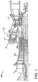
- FIG. 1 depicts a schematic illustration of an illustrative turbomachine 100 in the form of a combustion or gas turbine system.
- the turbomachine 100 includes a compressor section 102 and a combustor section 104.
- the combustor section 104 includes a headend portion 106 including a fuel nozzle assembly 108, and a combustion region 110.
- the turbomachine 100 also includes a turbine section 112 and a common compressor/turbine shaft 114 (sometimes referred to as rotor 114).
- the combustion turbine system is a 7HA or 9HA engine, commercially available from General Electric Company, Greenville, S.C.
Landscapes
- Engineering & Computer Science (AREA)
- Mechanical Engineering (AREA)
- General Engineering & Computer Science (AREA)
- Chemical & Material Sciences (AREA)
- Combustion & Propulsion (AREA)
- Materials Engineering (AREA)
- Polishing Bodies And Polishing Tools (AREA)
- Grinding Of Cylindrical And Plane Surfaces (AREA)
- Finish Polishing, Edge Sharpening, And Grinding By Specific Grinding Devices (AREA)
Abstract
Description
- The disclosure relates generally to a turbomachine, and more particularly, to a tool and repair method for the removal of a thermal barrier coating (TBC) from a surface of a component of a turbomachine.
- A gas turbine system typically includes a compressor section, a combustor section, and at least one turbine section. The compressor section compresses air that is mixed with fuel, provided via a fuel nozzle assembly. The air/fuel mixture is delivered to the combustor section and then ignited generating hot combustion gases. The combustion gases are directed to the turbine section, which extracts energy from the combustion gases for producing useful work to power a load, such as an electrical generator, as well as for powering the compressor section.
- The combustor section may include a combustion liner that defines a combustion region and a transition piece that connects an outlet end of the combustor section with an inlet end of the turbine section to deliver the hot combustion gasses to the turbine section. In some cases, in an effort to decrease the number of individual components within the combustor system, the combustion liner and the transition piece of the combustor section may be combined into a unibody component.
- Thermal barrier coatings (TBCs) are often used to protect and insulate various metal components (e.g., unibody component, turbine blades, etc.) in a gas turbine system that are exposed to high-temperature environments. TBCs also provide resistance to corrosion and oxidation. TBCs are generally deposited onto a metal substrate (or more typically onto a bond coat layer on the metal substrate for better adherence).
- In some cases, during operation, components of a gas turbine system may expand due to high operational temperatures. Such expansion may cause a section of a component (e.g., a headend portion) to contact the TBC at an inlet end of the unibody component. This may cause TBC damage at the contact point and downstream of the contact point.
- All aspects, examples and features mentioned below can be combined in any technically possible way.
- An aspect of the disclosure provides a tool for removing a coating from an interior surface of a component, including: a rotary device; a grinding attachment attached to the rotary device; a tool holder configured to: set an axial position of the grinding attachment coupled to the rotary device over the coating on the interior surface of the component; and set a radial position of the grinding attachment coupled to the rotary device, the radial position defining a cutting depth of the grinding attachment into the coating on the interior surface of the component; and a wheel assembly coupled to the tool holder for guiding the tool holder about an interior perimeter of the component.
- In another aspect of the disclosure, the tool holder includes a base and a collet assembly coupled to the base for securing the rotary device.
- In another aspect of the disclosure, the tool further includes at least one biasing member for mounting the collet assembly to the base, wherein the at least biasing member is configured to spring load the collet assembly toward the base.
- In another aspect of the disclosure, the collet assembly includes an upper section, a lower section, and a handwheel coupled to a threaded shaft for selectively displacing the upper section of the collet assembly toward or away from the lower section of the collet assembly.
- In another aspect of the disclosure, the collet assembly includes a handwheel, coupled to a threaded shaft, for selectively displacing the collet assembly toward or away from the base to set the cutting depth of the grinding attachment into the coating on the interior surface of the component, wherein the threaded shaft extends through the collet assembly to the base, and a depth limiter for setting a maximum cutting depth of the grinding attachment into the coating on the interior surface of the component.
- In another aspect of the disclosure, the axial position of the initial cut defines a maximum axial distance into the component.
- In another aspect of the disclosure, the component includes a combustion component of a gas turbine system.
- In another aspect of the disclosure, the combustion component includes a unibody component or a liner.
- In another aspect of the disclosure, the combustion component includes a flange extending about the interior perimeter of the combustion component, and the wheel assembly coupled to the tool holder is configured to guide the tool holder along the flange.
- In another aspect of the disclosure, the wheel assembly includes at least one first wheel rotatably mounted to the tool holder for engaging the interior surface of the combustion component, at least one second wheel rotatably mounted to the tool holder for engaging an outside edge of the flange, and at least one pair of third wheels rotatably mounted to the tool holder for engaging opposing sides of the flange.
- In another aspect of the disclosure,, the coating comprises a thermal barrier coating (TBC).
- A further aspect of the disclosure includes a method for removing a thermal barrier coating (TBC) from an interior surface of a combustion component of a gas turbine system, including: positioning a tool within an interior of the combustion component, wherein the tool includes: a rotary device; a grinding attachment attached to the rotary device; a tool holder coupled to the rotary device; and a wheel assembly coupled to the tool holder for guiding the tool about an interior perimeter of the combustion component; setting an initial axial position of the grinding attachment of the rotary device within the interior of the combustion component; setting a radial position of the grinding attachment of the rotary device within the interior of the combustion component to form an initial cut into the TBC; and adjusting the axial position and the radial position of the grinding attachment of the rotary device within the interior of the combustion component to form additional cuts into the TBC.
- In another aspect of the disclosure the method also includes, after forming the initial cut and the additional cuts into the TBC, attaching a polishing attachments to the rotary device, and removing additional TBC using the polishing attachment.
- In another aspect of the disclosure, the method also includes displacing the tool about the interior perimeter of the combustion component when forming the initial cut and the additional cuts.
- In another aspect of the disclosure, the initial cut defines a maximum axial distance from an edge of the TBC, wherein the additional cuts are formed between the initial cut and the edge of the TBC.
- In another aspect of the disclosure, the method also includes tapering an edge of the TBC.
- In another aspect of the disclosure, the combustion component includes an internal feature that extends about the interior perimeter of the combustion component, and the wheel assembly is configured to guide the tool holder along the internal feature of the combustion component.
- In another aspect of the disclosure, the method also includes providing a constant downward pressure of the grinding attachment against the TBC.
- In another aspect of the disclosure, the method is performed at an operational site of the gas turbine system.
- In another aspect of the disclosure, the combustion component includes a unibody component or a liner.
- Two or more aspects described in this disclosure, including those described in this summary section, may be combined to form implementations not specifically described herein.
- The details of one or more implementations are set forth in the accompanying drawings and the description below. Other features, aspects and advantages will be apparent from the description and drawings, and from the claims.
- These and other features of this disclosure will be more readily understood from the following detailed description of the various aspects of the disclosure taken in conjunction with the accompanying drawings that depict various embodiments of the disclosure in which:
-
FIG. 1 shows a schematic view of an illustrative turbomachine in the form of a gas turbine system; -
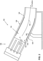
FIG. 2 is a cross-sectional view of a combustor section of a gas turbine system; -
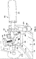
FIG. 3 depicts a tool for removing a thermal barrier coating (TBC) from a surface of a component (e.g., unibody component) of a gas turbine system according to embodiments of the disclosure; -
FIG. 4 depicts an operational displacement of the tool ofFIG. 3 according to embodiments of the disclosure, when viewed in the direction indicated by arrow A inFIG. 2 ; -
FIG. 5 is a perspective view of the tool ofFIG. 3 according to embodiments of the disclosure, with the tool positioned against an interior surface of a unibody component; -
FIG. 6 is a perspective view of the tool ofFIG. 3 according to embodiments of the disclosure; -
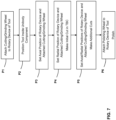
FIG. 7 is a flow diagram of an illustrative process for selectively removing TBC from an interior surface of a unibody component of a gas turbine system according to embodiments of the disclosure; -
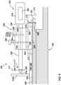
FIG. 8 depicts a positioning of the tool ofFIG. 3 within a unibody component according to embodiments of the disclosure; -
FIG. 9 depicts an axial positioning of a grinding/polishing attachment of the tool depicted inFIG. 8 according to embodiments of the disclosure; -
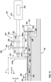
FIG. 10 depicts a radial positioning of the grinding/polishing attachment of the tool ofFIG. 9 , and an initial cut made in the TBC by the grinding/polishing attachment of the tool, according to embodiments of the disclosure; -
FIG. 11 depicts the tool ofFIG. 10 after several additional cuts have been made in the TBC by the grinding/polishing attachment of the tool according to embodiments of the disclosure; -
FIG. 12 depicts the tool ofFIG. 11 when configured to for polishing according to embodiments of the disclosure; and -
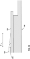
FIG. 13 depicts the unibody component ofFIG. 12 after removal of the TBC according to embodiments of the disclosure. - It is noted that the drawings of the disclosure are not necessarily to scale. The drawings are intended to depict only typical aspects of the disclosure and therefore should not be considered as limiting the scope of the disclosure. In the drawings, like numbering represents like elements between the drawings.
- As an initial matter, in order to clearly describe the subject matter of the current disclosure, it will become necessary to select certain terminology when referring to and describing relevant machine components within a turbomachine and/or a turbomachine blade. To the extent possible, common industry terminology will be used and employed in a manner consistent with its accepted meaning. Unless otherwise stated, such terminology should be given a broad interpretation consistent with the context of the present application and the scope of the appended claims. Those of ordinary skill in the art will appreciate that often a particular component may be referred to using several different or overlapping terms. What may be described herein as being a single part may include and be referenced in another context as consisting of multiple components. Alternatively, what may be described herein as including multiple components may be referred to elsewhere as a single part.
- In addition, several descriptive terms may be used regularly herein, and it should prove helpful to define these terms at the onset of this section. These terms and their definitions, unless stated otherwise, are as follows. As used herein, "downstream" and "upstream" are terms that indicate a direction relative to the flow of a fluid, such as the working fluid through the turbine engine or, for example, the flow of air through the combustor or coolant through one of the turbine's component systems. The term "downstream" corresponds to the direction of flow of the fluid, and the term "upstream" refers to the direction opposite to the flow (i.e., the direction from which the flow originates). The terms "forward" and "aft," without any further specificity, refer to directions, with "forward" referring to the front or compressor end of the engine, and "aft" referring to the rearward section of the turbomachine.
- It is often required to describe parts that are disposed at differing radial positions with regard to a center axis. The term "radial" refers to movement or position perpendicular to an axis. For example, if a first component resides closer to the axis than a second component, it will be stated herein that the first component is "radially inward" or "inboard" of the second component. If, on the other hand, the first component resides further from the axis than the second component, it may be stated herein that the first component is "radially outward" or "outboard" of the second component. The term "axial" refers to movement or position parallel to the axis of rotation of the turbine system, or in a chordal direction between leading and trailing edges of an airfoil. Finally, the term "circumferential" refers to movement or position around an axis. It will be appreciated that such terms may be applied in relation to the center axis of the turbine.
- In addition, several descriptive terms may be used regularly herein, as described below. The terms "first", "second", and "third" may be used interchangeably to distinguish one component from another and are not intended to signify location or importance of the individual components.
- The terminology used herein is for the purpose of describing particular embodiments only and is not intended to be limiting of the disclosure. As used herein, the singular forms "a", "an" and "the" are intended to include the plural forms as well, unless the context clearly indicates otherwise. It will be further understood that the terms "comprises" and/or "comprising," when used in this specification, specify the presence of stated features, integers, steps, operations, elements, and/or components but do not preclude the presence or addition of one or more other features, integers, steps, operations, elements, components, and/or groups thereof. "Optional" or "optionally" means that the subsequently described event or circumstance may or may not occur or that the subsequently describe component or element may or may not be present, and that the description includes instances where the event occurs or the component is present and instances where it does not or is not present.
- Where an element or layer is referred to as being "on," "engaged to," "connected to" or "coupled to" another element or layer, it may be directly on, engaged to, connected to, or coupled to the other element or layer, or intervening elements or layers may be present. In contrast, when an element is referred to as being "directly on," "directly engaged to," "directly connected to" or "directly coupled to" another element or layer, there may be no intervening elements or layers present. Other words used to describe the relationship between elements should be interpreted in a like fashion (e.g., "between" versus "directly between," "adjacent" versus "directly adjacent," etc.). As used herein, the term "and/or" includes any and all combinations of one or more of the associated listed items.
-
FIG. 1 depicts a schematic illustration of anillustrative turbomachine 100 in the form of a combustion or gas turbine system. As shown, theturbomachine 100 includes acompressor section 102 and acombustor section 104. Thecombustor section 104 includes aheadend portion 106 including afuel nozzle assembly 108, and acombustion region 110. Theturbomachine 100 also includes aturbine section 112 and a common compressor/turbine shaft 114 (sometimes referred to as rotor 114). In one embodiment, the combustion turbine system is a 7HA or 9HA engine, commercially available from General Electric Company, Greenville, S.C. - The present disclosure is not limited to any one particular combustion or gas turbine system and may be implanted in connection with other engines including, for example, various HA, F, B, LM, GT, TM and E-class engine models of General Electric Company and engine models of other companies. Further, the teachings of the disclosure are not necessarily applicable to only a combustion or gas turbine system and may be applied to other types of turbomachines, e.g., steam turbines, jet engines, compressors, etc.
- In operation, air flows through the
compressor section 102 and compressed air is supplied to thecombustor section 104. Specifically, the compressed air is supplied to thefuel nozzle assembly 108, which is in flow communication with thecombustion region 110. Thefuel nozzle assembly 108 is also in flow communication with a fuel source (not shown inFIG. 1 ) and channels fuel and air to thecombustion region 110. Thecombustor section 104 ignites and combusts the fuel/air mixture. - The
combustor section 104 is in flow communication with theturbine section 112. The hot combustion gases produced by thecombustor section 104 are directed into theturbine section 112 and are converted mechanical rotational energy. Theturbine section 112 is rotatably coupled to and drivesrotor 114. Thecompressor section 102 also is rotatably coupled torotor 114. -
FIG. 2 depicts a simplified cross-sectional illustration of thecombustor section 104. As shown, thecombustor section 104 may include acombustion region 110 including acombustion liner 120 and atransition piece 122 for deliveringhot combustion gases 124 produced by thecombustor section 104 to theturbine section 112. According to embodiments, thecombustion liner 120 and thetransition piece 122 of thecombustor section 104 may be combined into asingle combustion component 126, including but not limited to a "unibody"component 126 from General Electric Company. A thermal barrier coating (TBC) 128 may be formed, for example, on aninterior surface 130 of theunibody component 126. - In some cases, during operation, components of the
gas turbine system 100 may expand due to high operational temperatures. For example, a section of theheadend portion 106 may expand and contact theTBC 128 on theinterior surface 130 of an inlet end 132 (e.g., forward or upstream end) of theunibody component 126. This may cause damage to theTBC 128 at the contact point and downstream of the contact point. To prevent such damage to theTBC 128, it may be necessary to remove a portion of theTBC 128 at or adjacent the contact point. In the past, such removal of theTBC 128 from theinterior surface 130 of theinlet end 132 of theunibody component 126 would require a servicing of theunibody component 126 at a repair or manufacturing site, which could often take several months. - A tool and repair method that allows the removal (e.g., in situ) of a layer of material (e.g., TBC) from a surface (e.g., interior surface) of a component of a gas turbine system (e.g., a unibody component, liner, etc.) according to embodiments will now be described. Although described herein for use with a unibody component of a gas turbine system, it should be clear that the tool and repair method may be used to remove TBC or other material layer from surface(s) of other components of a gas turbine system or other systems/machines.
- The tool is a custom fixture that can attach to a portion of a unibody component such that it can 'ride' around the perimeter of the unibody component to carefully and consistently machine or grind down the TBC on an interior surface to a desired thickness. The repair method includes use of a grinding wheel (e.g., a diamond grinding wheel) to first score an initial cut into the TBC (e.g., at a maximum axial distance from the edge of the TBC) to protect the TBC that will remain on the unibody component after the removal process. After the initial cut, multiple additional cuts can be formed in the TBC to remove the bulk of the TBC. The grinding wheel is then replaced with a polishing wheel (e.g., diamond flapper wheel) to remove the remaining TBC and to polish and smooth the base metal and bond coat surface.
- A
tool 200 for removing a portion of a layer ofTBC 128 from aninterior surface 130 of aunibody component 126 according to embodiments is depicted inFIGS. 3 ,5 and6 .FIG. 4 depicts an operational displacement of thetool 200 when viewed in the direction indicated by arrow A (i.e., downstream) inFIG. 2 . - According to embodiments, the
tool 200 is configured to ride along an interior perimeter of theunibody component 126. In some cases, as depicted inFIGS. 3 and4 , theunibody component 126 may include aninterior flange 208 that extends about an interior perimeter of theunibody component 126. In such a case, thetool 200 may be configured to ride along theflange 208 about the interior perimeter of theunibody component 126. If noflange 208 is present, thetool 200 may be modified accordingly to ride about the interior perimeter of theunibody component 126. - Referring now to
FIGS. 3 ,5 , and6 , thetool 200 may include arotary device 210 that includes a rotatable grinding/polishingattachment 212. As shown, the grinding/polishingattachment 212 may include agrinding wheel 214A (e.g., a diamond grinding wheel,FIG. 5 ) or apolishing wheel 214B (e.g., a diamond flapper wheel,FIG. 6 ) coupled to ashaft 216. Other types of grinding/polishing wheels and/or rotary device attachments capable of removingTBC 128 from a surface may also be employed. Also, according to embodiments, therotary device 210 may comprise a pneumatic die grinder or other device capable of rotating the grinding/polishingattachment 212. - The
rotary device 210 may include ahandle 218 that houses a motor 220 (e.g., pneumatic motor), ahousing 222, and arotatable spindle 224 driven by themotor 220. Thespindle 224 extends through and out of thehousing 222 and includes acollet 226 for releasably coupling the grinding/polishingattachment 212 to thespindle 224. - The
tool 200 may also include a tool holder including abase 228 and acollet assembly 230 coupled to thebase 228. Thecollet assembly 230 may include anupper section 232, alower section 234, and ahandwheel 236 for selectively displacing theupper section 232 of thecollet assembly 230 towards or away from thelower section 234 to secure or release therotary device 210. Thehandwheel 236 may be coupled to a threadedshaft 238 that extends through theupper section 232 of thecollet assembly 230 to thelower section 234. - The
collet assembly 230 may be used to set an axial position of the rotary device 210 (e.g., into and out of theunibody component 126 as depicted by arrow B,FIG. 3 ). This allows an operator to selectively set the axial position of the grinding/polishingattachment 212 over a portion of theTBC 128 that is to be removed. In some cases, a portion of abond coat layer 202 formed between theTBC 128 and theinterior surface 130 of theunibody component 126 may also be removed using the grinding/polishingattachment 212 of therotary device 210. - In operation, the axial position of the
rotary device 210 and the grinding/polishingattachment 212 of thetool 200 may be adjusted by rotating thehandwheel 236 and attached threadedshaft 238 in a first direction to displace theupper section 232 of thecollet assembly 230 away from thelower section 234, thereby releasing therotary device 210. Therotary device 210 and the grinding/polishingattachment 212 may then be repositioned to a desired axial position on thetool 200. Thereafter, thehandwheel 236 and attached threadedshaft 238 may be rotated in a second, opposite direction to move theupper section 232 of thecollet assembly 230 toward thelower section 234, thereby retightening thecollet assembly 230 about therotary device 210. - According to embodiments, a
handwheel 240 and attached threadedshaft 242 may also be used to set the radial position of therotary device 210 and attached grinding/polishingattachment 212 of the tool 100 (e.g., toward and away from theinterior surface 130 of theunibody component 126 as depicted by arrow C,FIG. 3 ). As depicted inFIG. 3 , the threadedshaft 242 may extend through the upper andlower sections collet assembly 230 to a surface of thebase 228. A depth limiter 244 (e.g., a locking knob) may be provided to limit the amount of radial displacement of therotary device 210 and grinding/polishingattachment 212 toward theinterior surface 130 of theunibody component 126, for example to prevent the grinding/polishingattachment 212 of therotary device 210 from damaging the metal surface (e.g., interior surface 130) of theunibody component 126. - In operation, the radial position of the
rotary device 210 and the grinding/polishingattachment 212 of thetool 200 may be adjusted by rotating thehandwheel 240 and attached threadedshaft 242 in a first direction to move thecollet assembly 230 toward thebase 228. Similarly, thehandwheel 240 and attached threadedshaft 242 may be rotated in a second, opposite direction to move thecollet assembly 230 away from thebase 228. To this extent, the cutting depth of the grinding/polishingattachment 212 of therotary device 210 may be adjusted as needed. - According to embodiments, as can be seen in
FIGS. 3 and5 , thetool 200 may include at least one biasingmember 250 for coupling thecollet assembly 230 to thebase 228 and for spring loading the collet assembly 230 (and attached rotary device 210) downward toward thebase 228. The biasing member(s) 250 may be attached between thelower section 234 of thecollet assembly 230 and thebase 228 and may be configured to provide a controlled (e.g., constant) downward pressure on thecollet assembly 230,rotary device 210, and grinding/polishingattachment 212. - The
tool 200 may include a wheel assembly including at least one set of wheels for enabling thetool 200 to travel (e.g., ride) along the profile of the unibody component 126 - even if theunibody component 126 is out of round. For example, as depicted inFIGS. 3 ,5 , and6 , thetool 200 may include a first set ofwheels 270 that are rotatably mounted to, and extend forward of, thebase 228 of thetool 200. The first set ofwheels 270 may include at least onewheel 270 that is configured to roll on theinterior surface 130 of theunibody component 126. Asingle wheel 270 mounted to a center of aforward edge 272 of thebase 228 is depicted inFIGS. 3 ,5 and6 , although more than onewheel 270 may be provided. - A
back plate 274 may be coupled to a rear 276 of thebase 228 of thetool 200. According to embodiments, a second set ofwheels 280 may be rotatably mounted to theback plate 274 of thebase 228. The second set ofwheels 280 may include at least onewheel 280 that is configured to roll against anoutside edge 282 of theflange 208 of theunibody component 126. As best seen inFIGS. 5 and6 , a pair ofwheels 280 may be rotatably mounted on opposing sides of theback plate 274 of thebase 228, although onewheel 280 or more than twowheels 280 may be provided. - A third set of
wheels 290 may also be rotatably mounted to theback plate 274 of thebase 228. The third set ofwheels 290 may include at least one pair of offsetwheels 290 that are configured to roll against opposing top and bottom sides of theflange 208 of theunibody component 126. As best seen inFIGS. 5 and6 , two pairs ofwheels 290 may be provided, although one pair ofwheels 290 or more than two pairs ofwheels 290 may be employed. - If the
flange 208 is not present, the second set ofwheels 280 may not be required. Further, in such a case, one or more of thewheels 290 mounted to theback plate 274 of the base 228 may be provided to roll against theinterior surface 130 of theunibody component 126. - A flow diagram of an illustrative process for selectively removing
TBC 128 from theinterior surface 130 of aunibody component 126 according to embodiments is depicted inFIG. 7 . Corresponding views of thetool 200 in operation are depicted inFIGS. 8-12 . - At process P1, a
grinding wheel 214A is attached to therotary device 210 of thetool 200. At process P2, thetool 200 is moved into position at the inlet end 132 (FIG. 2 ) of the unibody component 126 (FIG. 8 ). - Assuming the
unibody component 126 includes theinterior flange 208, eachwheel 270 is positioned on theinterior surface 130 of theunibody component 126, eachwheel 280 is positioned against theoutside edge 282 of theflange 208, and each pair ofwheels 290 is positioned against opposing top and bottom sides of theflange 208. Thereafter, in process P3, as depicted inFIG. 9 , the axial position of therotary device 210 and attachedgrinding wheel 214A of thetool 200 may be modified/set by loosening thehandwheel 236, displacing therotary device 210 and attachedgrinding wheel 214A to a desired position within thecollet assembly 230, and retightening thehandwheel 236. - As depicted in
FIG. 10 , at process P4, aninitial cut 300 is scored in theTBC 128 by thegrinding wheel 214A attached to the rotary device 210 (e.g., at a maximum axial distance D from theedge 302 of the TBC 128) to delineate the portion of theTBC 128 that is to be removed. Thehandwheel 240 and attached threadedshaft 242 may be manipulated as necessary to displace thegrinding wheel 214A against and into theTBC 128 to a desired cutting depth during the cutting process. - At process P5, after the
initial cut 300, the axial and radial positions of therotary device 210 and attachedgrinding wheel 214A may be selectively adjusted as described above to create multipleadditional cuts 304 in theTBC 128 to remove the bulk of theTBC 128 from theinterior surface 130 of the unibody component 126 (e.g., from theedge 302 of theTBC 128 to the maximum axial distance D defined by the initial cut 300). If necessary, thecuts bond coat 202 to remove portions of thebond coat 202. - At process P6, the
grinding wheel 214A attached to therotary device 210 may be replaced with apolishing wheel 214B (e.g., diamond flapper wheel) to remove any remainingTBC 128 and to polish and smooth the base metal (e.g.,interior surface 130 of the unibody 126) and, if necessary, the surface of thebond coat 202. The axial and radial positions of therotary device 210 and attachedpolishing wheel 214B may be selectively adjusted as described above. - As previously described with regard to
FIG. 4 , thetool 200 may include at least one set ofwheels tool 200 to easily travel (e.g., ride) along the profile of theunibody component 126. To this extent, an operator of thetool 200 can guide thetool 200 about theunibody component 126 while performing the grinding/polishing operations. This may include, for example, forming theinitial cut 300 by displacing thetool 200 about the entire interior perimeter of theunibody component 126. Thereafter, the operator may focus on separate arcuate sections of theTBC 128 when making theadditional cuts 304 and during polishing. Alternatively, the operator may displace thetool 200 about the entire interior perimeter of theunibody component 126 while making theadditional cuts 304. Other techniques are, of course, possible. -
FIG. 13 depicts theinterior surface 130 of theunibody component 126 after the complete removal of the TBC 128 (and bond coat 202) for a distance D from the original edge 302 (FIG. 10 ) of theTBC 128. In some cases, however, it may not be necessary to remove all of theTBC 128 in this area. Instead, theTBC 128 may be removed in a tapered manner as shown in phantom inFIG. 13 by adjusting the radial position of therotary device 210 and thegrinding wheel 214A of thetool 200 to providecuts FIG. 13 . Other profiles are also possible. - Embodiments of the disclosure can drastically reduce the amount of downtime required to remove TBC from a component (e.g., a unibody component) of a turbomachine. In the past, the removal of the TBC from the interior surface of a unibody component would require the component to be shipped to a repair or manufacturing site where the TBC would be removed, which could often take several months. Advantageously, the
tool 200 according to embodiments may be used in situ during on-site assembly of the turbomachine, reducing the downtime from several months to a few weeks or even days. - Approximating language, as used herein throughout the specification and claims, may be applied to modify any quantitative representation that could permissibly vary without resulting in a change in the basic function to which it is related. Accordingly, a value modified by a term or terms, such as "about," "approximately" and "substantially," are not to be limited to the precise value specified. In at least some instances, the approximating language may correspond to the precision of an instrument for measuring the value. Here and throughout the specification and claims, range limitations may be combined and/or interchanged; such ranges are identified and include all the sub-ranges contained therein unless context or language indicates otherwise. "Approximately," as applied to a particular value of a range, applies to both end values and, unless otherwise dependent on the precision of the instrument measuring the value, may indicate +/- 10% of the stated value(s).
- The corresponding structures, materials, acts, and equivalents of all means or step plus function elements in the claims below are intended to include any structure, material, or act for performing the function in combination with other claimed elements as specifically claimed. The description of the present disclosure has been presented for purposes of illustration and description but is not intended to be exhaustive or limited to the disclosure in the form disclosed. Many modifications and variations will be apparent to those of ordinary skill in the art without departing from the scope and spirit of the disclosure. The embodiment was chosen and described in order to best explain the principles of the disclosure and the practical application and to enable others of ordinary skill in the art to understand the disclosure for various embodiments with various modifications as are suited to the particular use contemplated.
Claims (15)
- A tool (200) for removing a coating from an interior surface (130) of a component (126), comprising:a rotary device (210);a grinding attachment (214A) attached to the rotary device (210);a tool holder configured to:set an axial position of the grinding attachment (214A) coupled to the rotary device (210) over the coating (128) on the interior surface (130) of the component (126); andset a radial position of the grinding attachment (214A) coupled to the rotary device (210), the radial position defining a cutting depth of the grinding attachment (214A) into the coating (128) on the interior surface (130) of the component (126); anda wheel assembly (270, 280, 290) coupled to the tool holder for guiding the tool holder about an interior perimeter of the component (126).
- The tool (200) according to claim 1, wherein the tool holder further comprises a base (228) and a collet assembly (230) coupled to the base (228) for securing the rotary device (210).
- The tool (200) according to claim 2, further comprising at least one biasing member (250) for mounting the collet assembly (230) to the base (228), wherein the at least biasing member (250) is configured to spring load the collet assembly (230) toward the base (228).
- The tool (200) according to claim 2, wherein the collet assembly (230) further comprises:an upper section (232);a lower section (234); anda handwheel (236) coupled to a threaded shaft (238) for selectively displacing the upper section (232) of the collet assembly (230) toward or away from the lower section (234) of the collet assembly (230).
- The tool (200) according to claim 2, wherein the collet assembly (230) further comprises:a handwheel (240), coupled to a threaded shaft (242), for selectively displacing the collet assembly (230) toward or away from the base (228) to set the cutting depth of the grinding attachment (214A) into the coating (128) on the interior surface (130) of the component (126), wherein the threaded shaft (242) extends through the collet assembly (230) to the base (228); anda depth limiter (244) for setting a maximum cutting depth of the grinding attachment (214A) into the coating (128) on the interior surface (130) of the component (126).
- The tool (200) of claim 1, wherein the axial position of the initial cut (300) defines a maximum axial distance into the component (126).
- The tool (200) according to claim 1, wherein the component (126) comprises a combustion component of a gas turbine system (100).
- The tool (200) according to claim 6, wherein the combustion component includes a unibody component (126) or a liner (120).
- The tool (200) according to claim 7, wherein the combustion component (126) includes a flange (208) extending about the interior perimeter of the combustion component (126), and wherein the wheel (270, 280, 290) assembly (270, 280, 290) coupled to the tool holder is configured to guide the tool holder along the flange (208).
- The tool (200) according to claim 9, wherein the wheel assembly (270, 280, 290) further comprises:at least one first wheel (270) rotatably mounted to the tool holder for engaging the interior surface (130) of the combustion component (126);at least one second wheel (280) rotatably mounted to the tool holder for engaging an outside edge (282) of the flange (208); andat least one pair of third wheels (290) rotatably mounted to the tool holder for engaging opposing sides of the flange (208).
- The tool (200) of claim 1, wherein the coating comprises a thermal barrier coating (TBC) (128).
- A method for removing a thermal barrier coating (TBC) (128) from an interior surface (130) of a combustion component (126) of a gas turbine system (100), comprising:positioning a tool (200) within an interior of the combustion component (126), wherein the tool (200) comprises:a rotary device (210);a grinding attachment (214A) attached to the rotary device (210);a tool holder coupled to the rotary device (210); anda wheel assembly (270, 280, 290) coupled to the tool holder for guiding the tool (200) about an interior perimeter (130) of the combustion component (126);setting an initial axial position of the grinding attachment (214A) of the rotary device (210) within the interior of the combustion component (126);setting a radial position of the grinding attachment (214A) of the rotary device (210) within the interior of the combustion component (126) to form an initial cut (300) into the TBC (128); andadjusting the axial position and the radial position of the grinding attachment (214A) of the rotary device (210) within the interior of the combustion component (126) to form additional cuts (304) into the TBC (128).
- The method according to claim 12, further comprising, after forming the initial cut (300) and the additional cuts (304) into the TBC (128):attaching a polishing attachment (214B) to the rotary device (210); andremoving additional TBC (128) using the polishing attachment (214B).
- The method according to claim 12, further comprising:
displacing the tool (200) about the interior perimeter of the combustion component (126) when forming the initial cut (300) and the additional cuts (304). - The method according to claim 12, wherein the initial cut (300) defines a maximum axial distance from an edge (302) of the TBC (128), wherein the additional cuts (304) are formed between the initial cut (300) and the edge (302) of the TBC (128).
Applications Claiming Priority (1)
| Application Number | Priority Date | Filing Date | Title |
|---|---|---|---|
| US17/490,339 US20230101193A1 (en) | 2021-09-30 | 2021-09-30 | Tool and repair method for removing a thermal barrier coating |
Publications (2)
| Publication Number | Publication Date |
|---|---|
| EP4159370A1 true EP4159370A1 (en) | 2023-04-05 |
| EP4159370B1 EP4159370B1 (en) | 2025-10-29 |
Family
ID=83283256
Family Applications (1)
| Application Number | Title | Priority Date | Filing Date |
|---|---|---|---|
| EP22195039.7A Active EP4159370B1 (en) | 2021-09-30 | 2022-09-12 | Tool and repair method for removing a thermal barrier coating |
Country Status (5)
| Country | Link |
|---|---|
| US (2) | US20230101193A1 (en) |
| EP (1) | EP4159370B1 (en) |
| JP (1) | JP2023051764A (en) |
| KR (1) | KR20230047007A (en) |
| CN (1) | CN115890249A (en) |
Families Citing this family (1)
| Publication number | Priority date | Publication date | Assignee | Title |
|---|---|---|---|---|
| CN120461208B (en) * | 2025-06-05 | 2025-11-11 | 唐山永丰轧辊有限公司 | Roller equipment of polishing |
Citations (6)
| Publication number | Priority date | Publication date | Assignee | Title |
|---|---|---|---|---|
| JPS5796755U (en) * | 1980-11-29 | 1982-06-14 | ||
| CN202097616U (en) * | 2010-12-31 | 2012-01-04 | 浙江汉成特殊钢管有限公司 | Wall uniform machine for steel tube |
| CN103506903A (en) * | 2013-10-30 | 2014-01-15 | 江苏乐基重工机械有限公司 | Pipe inner wall grinding and polishing device |
| KR200471783Y1 (en) * | 2012-03-15 | 2014-03-14 | 대우조선해양 주식회사 | Portable polishing apparatus |
| WO2018017142A2 (en) * | 2016-07-21 | 2018-01-25 | Dtc Products, Inc. | Improved slug retention groove forming machine and method of use and operation thereof |
| US20190061091A1 (en) * | 2017-08-31 | 2019-02-28 | Wabash National, L.P. | Device for in-container operations |
Family Cites Families (21)
| Publication number | Priority date | Publication date | Assignee | Title |
|---|---|---|---|---|
| GB710252A (en) * | 1950-05-25 | 1954-06-09 | Napier & Son Ltd | Improvements in or relating to power plants incorporating gas turbines |
| US3613320A (en) * | 1969-10-08 | 1971-10-19 | Mary C Harter | Pipe machining method |
| JPS5930658A (en) * | 1982-08-07 | 1984-02-18 | Sumitomo Metal Ind Ltd | Repairing method of inside of pipe and device therefor |
| CN1177672C (en) * | 2001-06-21 | 2004-12-01 | 张军 | Machine-tool for comprehensively machining head of long-tube or long-axle parts |
| CA2454900C (en) * | 2003-01-08 | 2011-12-13 | Credo Technology Corporation | Attachment for power tool |
| US7004413B2 (en) * | 2003-05-02 | 2006-02-28 | Michel Langlois | Grinder cutter tooth and anvil assembly |
| US7241209B2 (en) * | 2004-08-13 | 2007-07-10 | General Electric Company | Orbiting polishing tool |
| US7029371B1 (en) * | 2005-06-17 | 2006-04-18 | Siemens Power Generation, Inc. | Jig for guiding a grinder |
| DE102008064564A1 (en) * | 2008-12-23 | 2010-06-24 | Flex-Elektrowerkzeuge Gmbh | Tool holding head for a hand-held cleaning / grinding machine and hand-held cleaning / grinding machine |
| US20120167388A1 (en) * | 2010-12-29 | 2012-07-05 | General Electric Company | System and method for disassembling turbine components |
| US8813331B2 (en) * | 2011-03-29 | 2014-08-26 | General Electric Company | Process of preparing a turbine rotor wheel, a repair wheel for a turbine rotor wheel, and a turbine rotor wheel |
| CA2789325C (en) * | 2011-10-27 | 2015-04-07 | United Technologies Corporation | Gas turbine engine front center body architecture |
| US9033657B2 (en) * | 2011-12-12 | 2015-05-19 | Honeywell International Inc. | Gas turbine engine including lift-off finger seals, lift-off finger seals, and method for the manufacture thereof |
| US8801502B2 (en) * | 2012-02-28 | 2014-08-12 | General Electric Company | In-situ airfoil contouring tool |
| EP2706198A1 (en) * | 2012-09-10 | 2014-03-12 | Alstom Technology Ltd | Method for removing an inner casing from a machine |
| CN103273319A (en) * | 2013-05-28 | 2013-09-04 | 郑国军 | Multifunctional processing machine capable of turning, grinding, drilling, milling, cutting, planing and boring |
| US20150275682A1 (en) * | 2014-04-01 | 2015-10-01 | Siemens Energy, Inc. | Sprayed haynes 230 layer to increase spallation life of thermal barrier coating on a gas turbine engine component |
| DE102016204338A1 (en) * | 2016-03-16 | 2017-09-21 | Bayerische Motoren Werke Aktiengesellschaft | deburring |
| CN106041652A (en) * | 2016-07-14 | 2016-10-26 | 泉州市科茂利通智能科技有限公司 | Pipe inner wall polishing robot based on parallel mechanism |
| US10711649B2 (en) * | 2018-05-31 | 2020-07-14 | Mitsubishi Hitachi Power Systems Americas, Inc. | Compressor casing repair assembly and method |
| US11338461B2 (en) * | 2019-04-26 | 2022-05-24 | General Electric Company | System for machining the abradable material of a turbofan engine |
-
2021
- 2021-09-30 US US17/490,339 patent/US20230101193A1/en active Pending
-
2022
- 2022-08-29 JP JP2022135504A patent/JP2023051764A/en active Pending
- 2022-09-05 CN CN202211095114.XA patent/CN115890249A/en active Pending
- 2022-09-12 EP EP22195039.7A patent/EP4159370B1/en active Active
- 2022-09-28 KR KR1020220122920A patent/KR20230047007A/en active Pending
-
2025
- 2025-11-20 US US19/395,355 patent/US20260077445A1/en active Pending
Patent Citations (6)
| Publication number | Priority date | Publication date | Assignee | Title |
|---|---|---|---|---|
| JPS5796755U (en) * | 1980-11-29 | 1982-06-14 | ||
| CN202097616U (en) * | 2010-12-31 | 2012-01-04 | 浙江汉成特殊钢管有限公司 | Wall uniform machine for steel tube |
| KR200471783Y1 (en) * | 2012-03-15 | 2014-03-14 | 대우조선해양 주식회사 | Portable polishing apparatus |
| CN103506903A (en) * | 2013-10-30 | 2014-01-15 | 江苏乐基重工机械有限公司 | Pipe inner wall grinding and polishing device |
| WO2018017142A2 (en) * | 2016-07-21 | 2018-01-25 | Dtc Products, Inc. | Improved slug retention groove forming machine and method of use and operation thereof |
| US20190061091A1 (en) * | 2017-08-31 | 2019-02-28 | Wabash National, L.P. | Device for in-container operations |
Also Published As
| Publication number | Publication date |
|---|---|
| US20230101193A1 (en) | 2023-03-30 |
| EP4159370B1 (en) | 2025-10-29 |
| KR20230047007A (en) | 2023-04-06 |
| JP2023051764A (en) | 2023-04-11 |
| CN115890249A (en) | 2023-04-04 |
| US20260077445A1 (en) | 2026-03-19 |
Similar Documents
| Publication | Publication Date | Title |
|---|---|---|
| US20260077445A1 (en) | Tool and repair method for removing a thermal barrier coating | |
| US8657570B2 (en) | Rotor blade with reduced rub loading | |
| EP2050927B1 (en) | Method for restoring airfoil tip contour | |
| US20100329863A1 (en) | Method for reducing tip rub loading | |
| EP2105245A2 (en) | Method for repairing an airfoil | |
| EP2819806B1 (en) | In-situ airfoil contouring tool | |
| US20230399949A1 (en) | Balancing weight entry port for turbine rotor | |
| CA2766534C (en) | Rotor blade and method for reducing tip rub loading | |
| EP2008759B1 (en) | Tool alignment fixture and method | |
| US20250230752A1 (en) | Methods of forming or repairing part with overhung section, and related turbomachine part | |
| CA3015255C (en) | Device and method for re-contouring a gas turbine blade | |
| EP4361399A1 (en) | Manufacturing method for forming an erosion shield and an erosion-shielded turbine blade | |
| EP4259904B1 (en) | Methods of forming or repairing part with overhung section, and related turbomachine part | |
| WO2025184546A1 (en) | Measuring and marking system for a turbine engine and related method | |
| EP4650056A1 (en) | Masking system | |
| EP2248929A1 (en) | Method of electrical discharge surface repair of a variable vane trunnion | |
| EP3604738B1 (en) | Laser tip cladding of a turbine blade to net-shape with a backing element | |
| CN119790217A (en) | Method for machining turbine components using reference surfaces |
Legal Events
| Date | Code | Title | Description |
|---|---|---|---|
| PUAI | Public reference made under article 153(3) epc to a published international application that has entered the european phase |
Free format text: ORIGINAL CODE: 0009012 |
|
| STAA | Information on the status of an ep patent application or granted ep patent |
Free format text: STATUS: THE APPLICATION HAS BEEN PUBLISHED |
|
| AK | Designated contracting states |
Kind code of ref document: A1 Designated state(s): AL AT BE BG CH CY CZ DE DK EE ES FI FR GB GR HR HU IE IS IT LI LT LU LV MC MK MT NL NO PL PT RO RS SE SI SK SM TR |
|
| STAA | Information on the status of an ep patent application or granted ep patent |
Free format text: STATUS: REQUEST FOR EXAMINATION WAS MADE |
|
| 17P | Request for examination filed |
Effective date: 20230927 |
|
| RBV | Designated contracting states (corrected) |
Designated state(s): AL AT BE BG CH CY CZ DE DK EE ES FI FR GB GR HR HU IE IS IT LI LT LU LV MC MK MT NL NO PL PT RO RS SE SI SK SM TR |
|
| RAP1 | Party data changed (applicant data changed or rights of an application transferred) |
Owner name: GENERAL ELECTRIC TECHNOLOGY GMBH |
|
| REG | Reference to a national code |
Ref country code: DE Ref legal event code: R079 Free format text: PREVIOUS MAIN CLASS: B24B0019140000 Ipc: B24B0027033000 Ref country code: DE Ref legal event code: R079 Ref document number: 602022023827 Country of ref document: DE Free format text: PREVIOUS MAIN CLASS: B24B0019140000 Ipc: B24B0027033000 |
|
| GRAP | Despatch of communication of intention to grant a patent |
Free format text: ORIGINAL CODE: EPIDOSNIGR1 |
|
| STAA | Information on the status of an ep patent application or granted ep patent |
Free format text: STATUS: GRANT OF PATENT IS INTENDED |
|
| RIC1 | Information provided on ipc code assigned before grant |
Ipc: B24B 23/02 20060101ALI20250304BHEP Ipc: B24B 23/00 20060101ALI20250304BHEP Ipc: B24B 27/033 20060101AFI20250304BHEP |
|
| INTG | Intention to grant announced |
Effective date: 20250319 |
|
| GRAS | Grant fee paid |
Free format text: ORIGINAL CODE: EPIDOSNIGR3 |
|
| RAP3 | Party data changed (applicant data changed or rights of an application transferred) |
Owner name: GE VERNOVA TECHNOLOGY GMBH |
|
| GRAA | (expected) grant |
Free format text: ORIGINAL CODE: 0009210 |
|
| STAA | Information on the status of an ep patent application or granted ep patent |
Free format text: STATUS: THE PATENT HAS BEEN GRANTED |
|
| AK | Designated contracting states |
Kind code of ref document: B1 Designated state(s): AL AT BE BG CH CY CZ DE DK EE ES FI FR GB GR HR HU IE IS IT LI LT LU LV MC MK MT NL NO PL PT RO RS SE SI SK SM TR |
|
| REG | Reference to a national code |
Ref country code: CH Ref legal event code: F10 Free format text: ST27 STATUS EVENT CODE: U-0-0-F10-F00 (AS PROVIDED BY THE NATIONAL OFFICE) Effective date: 20251029 Ref country code: GB Ref legal event code: FG4D |
|
| REG | Reference to a national code |
Ref country code: DE Ref legal event code: R096 Ref document number: 602022023827 Country of ref document: DE |
|
| REG | Reference to a national code |
Ref country code: IE Ref legal event code: FG4D |
|
| REG | Reference to a national code |
Ref country code: NL Ref legal event code: MP Effective date: 20251029 |
|
| PG25 | Lapsed in a contracting state [announced via postgrant information from national office to epo] |
Ref country code: ES Free format text: LAPSE BECAUSE OF FAILURE TO SUBMIT A TRANSLATION OF THE DESCRIPTION OR TO PAY THE FEE WITHIN THE PRESCRIBED TIME-LIMIT Effective date: 20251029 |
|
| REG | Reference to a national code |
Ref country code: LT Ref legal event code: MG9D |
|
| PG25 | Lapsed in a contracting state [announced via postgrant information from national office to epo] |
Ref country code: NO Free format text: LAPSE BECAUSE OF FAILURE TO SUBMIT A TRANSLATION OF THE DESCRIPTION OR TO PAY THE FEE WITHIN THE PRESCRIBED TIME-LIMIT Effective date: 20260129 |
|
| PG25 | Lapsed in a contracting state [announced via postgrant information from national office to epo] |
Ref country code: AT Free format text: LAPSE BECAUSE OF FAILURE TO SUBMIT A TRANSLATION OF THE DESCRIPTION OR TO PAY THE FEE WITHIN THE PRESCRIBED TIME-LIMIT Effective date: 20251029 Ref country code: FI Free format text: LAPSE BECAUSE OF FAILURE TO SUBMIT A TRANSLATION OF THE DESCRIPTION OR TO PAY THE FEE WITHIN THE PRESCRIBED TIME-LIMIT Effective date: 20251029 Ref country code: HR Free format text: LAPSE BECAUSE OF FAILURE TO SUBMIT A TRANSLATION OF THE DESCRIPTION OR TO PAY THE FEE WITHIN THE PRESCRIBED TIME-LIMIT Effective date: 20251029 |
|
| REG | Reference to a national code |
Ref country code: AT Ref legal event code: MK05 Ref document number: 1851062 Country of ref document: AT Kind code of ref document: T Effective date: 20251029 |
|
| PG25 | Lapsed in a contracting state [announced via postgrant information from national office to epo] |
Ref country code: NL Free format text: LAPSE BECAUSE OF FAILURE TO SUBMIT A TRANSLATION OF THE DESCRIPTION OR TO PAY THE FEE WITHIN THE PRESCRIBED TIME-LIMIT Effective date: 20251029 |
|
| PG25 | Lapsed in a contracting state [announced via postgrant information from national office to epo] |
Ref country code: RS Free format text: LAPSE BECAUSE OF FAILURE TO SUBMIT A TRANSLATION OF THE DESCRIPTION OR TO PAY THE FEE WITHIN THE PRESCRIBED TIME-LIMIT Effective date: 20260129 |
|
| PG25 | Lapsed in a contracting state [announced via postgrant information from national office to epo] |
Ref country code: IS Free format text: LAPSE BECAUSE OF FAILURE TO SUBMIT A TRANSLATION OF THE DESCRIPTION OR TO PAY THE FEE WITHIN THE PRESCRIBED TIME-LIMIT Effective date: 20260228 |
|
| PG25 | Lapsed in a contracting state [announced via postgrant information from national office to epo] |
Ref country code: PT Free format text: LAPSE BECAUSE OF FAILURE TO SUBMIT A TRANSLATION OF THE DESCRIPTION OR TO PAY THE FEE WITHIN THE PRESCRIBED TIME-LIMIT Effective date: 20260302 |
|
| PG25 | Lapsed in a contracting state [announced via postgrant information from national office to epo] |
Ref country code: PL Free format text: LAPSE BECAUSE OF FAILURE TO SUBMIT A TRANSLATION OF THE DESCRIPTION OR TO PAY THE FEE WITHIN THE PRESCRIBED TIME-LIMIT Effective date: 20251029 |
|
| PG25 | Lapsed in a contracting state [announced via postgrant information from national office to epo] |
Ref country code: LV Free format text: LAPSE BECAUSE OF FAILURE TO SUBMIT A TRANSLATION OF THE DESCRIPTION OR TO PAY THE FEE WITHIN THE PRESCRIBED TIME-LIMIT Effective date: 20251029 |
|
| PG25 | Lapsed in a contracting state [announced via postgrant information from national office to epo] |
Ref country code: BG Free format text: LAPSE BECAUSE OF FAILURE TO SUBMIT A TRANSLATION OF THE DESCRIPTION OR TO PAY THE FEE WITHIN THE PRESCRIBED TIME-LIMIT Effective date: 20251029 |
|
| PG25 | Lapsed in a contracting state [announced via postgrant information from national office to epo] |
Ref country code: LT Free format text: LAPSE BECAUSE OF FAILURE TO SUBMIT A TRANSLATION OF THE DESCRIPTION OR TO PAY THE FEE WITHIN THE PRESCRIBED TIME-LIMIT Effective date: 20251029 |
|
| PG25 | Lapsed in a contracting state [announced via postgrant information from national office to epo] |
Ref country code: SM Free format text: LAPSE BECAUSE OF FAILURE TO SUBMIT A TRANSLATION OF THE DESCRIPTION OR TO PAY THE FEE WITHIN THE PRESCRIBED TIME-LIMIT Effective date: 20251029 |
|
| PG25 | Lapsed in a contracting state [announced via postgrant information from national office to epo] |
Ref country code: DK Free format text: LAPSE BECAUSE OF FAILURE TO SUBMIT A TRANSLATION OF THE DESCRIPTION OR TO PAY THE FEE WITHIN THE PRESCRIBED TIME-LIMIT Effective date: 20251029 |
|
| PG25 | Lapsed in a contracting state [announced via postgrant information from national office to epo] |
Ref country code: EE Free format text: LAPSE BECAUSE OF FAILURE TO SUBMIT A TRANSLATION OF THE DESCRIPTION OR TO PAY THE FEE WITHIN THE PRESCRIBED TIME-LIMIT Effective date: 20251029 |
|
| PG25 | Lapsed in a contracting state [announced via postgrant information from national office to epo] |
Ref country code: CZ Free format text: LAPSE BECAUSE OF FAILURE TO SUBMIT A TRANSLATION OF THE DESCRIPTION OR TO PAY THE FEE WITHIN THE PRESCRIBED TIME-LIMIT Effective date: 20251029 |
|
| PG25 | Lapsed in a contracting state [announced via postgrant information from national office to epo] |
Ref country code: SK Free format text: LAPSE BECAUSE OF FAILURE TO SUBMIT A TRANSLATION OF THE DESCRIPTION OR TO PAY THE FEE WITHIN THE PRESCRIBED TIME-LIMIT Effective date: 20251029 |
|
| PG25 | Lapsed in a contracting state [announced via postgrant information from national office to epo] |
Ref country code: SE Free format text: LAPSE BECAUSE OF FAILURE TO SUBMIT A TRANSLATION OF THE DESCRIPTION OR TO PAY THE FEE WITHIN THE PRESCRIBED TIME-LIMIT Effective date: 20251029 |