EP4159306A1 - Solid bed level sensor for a biochar production system with a leveling actuator - Google Patents
Solid bed level sensor for a biochar production system with a leveling actuator Download PDFInfo
- Publication number
- EP4159306A1 EP4159306A1 EP22198287.9A EP22198287A EP4159306A1 EP 4159306 A1 EP4159306 A1 EP 4159306A1 EP 22198287 A EP22198287 A EP 22198287A EP 4159306 A1 EP4159306 A1 EP 4159306A1
- Authority
- EP
- European Patent Office
- Prior art keywords
- biochar
- controller
- bed level
- reactor
- production system
- Prior art date
- Legal status (The legal status is an assumption and is not a legal conclusion. Google has not performed a legal analysis and makes no representation as to the accuracy of the status listed.)
- Pending
Links
- 238000004519 manufacturing process Methods 0.000 title claims abstract description 48
- 239000007787 solid Substances 0.000 title description 7
- 239000002028 Biomass Substances 0.000 claims abstract description 46
- 230000000284 resting effect Effects 0.000 claims abstract description 4
- 238000000605 extraction Methods 0.000 claims description 23
- 238000000034 method Methods 0.000 claims description 23
- 230000003213 activating effect Effects 0.000 claims description 8
- 230000003247 decreasing effect Effects 0.000 claims 2
- 230000000977 initiatory effect Effects 0.000 claims 2
- 239000007789 gas Substances 0.000 description 11
- 230000033001 locomotion Effects 0.000 description 6
- 238000012986 modification Methods 0.000 description 4
- 230000004048 modification Effects 0.000 description 4
- 238000000197 pyrolysis Methods 0.000 description 4
- 238000010586 diagram Methods 0.000 description 3
- 239000000446 fuel Substances 0.000 description 3
- 238000005304 joining Methods 0.000 description 3
- 230000008569 process Effects 0.000 description 3
- OKTJSMMVPCPJKN-UHFFFAOYSA-N Carbon Chemical compound [C] OKTJSMMVPCPJKN-UHFFFAOYSA-N 0.000 description 2
- 239000000654 additive Substances 0.000 description 2
- 230000000996 additive effect Effects 0.000 description 2
- QVGXLLKOCUKJST-UHFFFAOYSA-N atomic oxygen Chemical compound [O] QVGXLLKOCUKJST-UHFFFAOYSA-N 0.000 description 2
- 229910052799 carbon Inorganic materials 0.000 description 2
- 238000001914 filtration Methods 0.000 description 2
- 238000005259 measurement Methods 0.000 description 2
- 229910052760 oxygen Inorganic materials 0.000 description 2
- 239000001301 oxygen Substances 0.000 description 2
- 239000002689 soil Substances 0.000 description 2
- 238000010408 sweeping Methods 0.000 description 2
- 230000008901 benefit Effects 0.000 description 1
- 230000005540 biological transmission Effects 0.000 description 1
- 230000008859 change Effects 0.000 description 1
- 238000006243 chemical reaction Methods 0.000 description 1
- 238000009833 condensation Methods 0.000 description 1
- 230000005494 condensation Effects 0.000 description 1
- 239000002826 coolant Substances 0.000 description 1
- 230000008878 coupling Effects 0.000 description 1
- 238000010168 coupling process Methods 0.000 description 1
- 238000005859 coupling reaction Methods 0.000 description 1
- 230000002950 deficient Effects 0.000 description 1
- 238000001514 detection method Methods 0.000 description 1
- 238000006073 displacement reaction Methods 0.000 description 1
- 239000002828 fuel tank Substances 0.000 description 1
- 230000005484 gravity Effects 0.000 description 1
- 238000010438 heat treatment Methods 0.000 description 1
- 239000000203 mixture Substances 0.000 description 1
- 239000011368 organic material Substances 0.000 description 1
- 230000001151 other effect Effects 0.000 description 1
- 238000010791 quenching Methods 0.000 description 1
- 239000000126 substance Substances 0.000 description 1
- 238000006467 substitution reaction Methods 0.000 description 1
- 239000011269 tar Substances 0.000 description 1
- XLYOFNOQVPJJNP-UHFFFAOYSA-N water Substances O XLYOFNOQVPJJNP-UHFFFAOYSA-N 0.000 description 1
Images




Classifications
-
- B—PERFORMING OPERATIONS; TRANSPORTING
- B01—PHYSICAL OR CHEMICAL PROCESSES OR APPARATUS IN GENERAL
- B01J—CHEMICAL OR PHYSICAL PROCESSES, e.g. CATALYSIS OR COLLOID CHEMISTRY; THEIR RELEVANT APPARATUS
- B01J6/00—Heat treatments such as Calcining; Fusing ; Pyrolysis
- B01J6/008—Pyrolysis reactions
-
- B—PERFORMING OPERATIONS; TRANSPORTING
- B01—PHYSICAL OR CHEMICAL PROCESSES OR APPARATUS IN GENERAL
- B01J—CHEMICAL OR PHYSICAL PROCESSES, e.g. CATALYSIS OR COLLOID CHEMISTRY; THEIR RELEVANT APPARATUS
- B01J8/00—Chemical or physical processes in general, conducted in the presence of fluids and solid particles; Apparatus for such processes
- B01J8/0015—Feeding of the particles in the reactor; Evacuation of the particles out of the reactor
- B01J8/002—Feeding of the particles in the reactor; Evacuation of the particles out of the reactor with a moving instrument
-
- B—PERFORMING OPERATIONS; TRANSPORTING
- B01—PHYSICAL OR CHEMICAL PROCESSES OR APPARATUS IN GENERAL
- B01J—CHEMICAL OR PHYSICAL PROCESSES, e.g. CATALYSIS OR COLLOID CHEMISTRY; THEIR RELEVANT APPARATUS
- B01J19/00—Chemical, physical or physico-chemical processes in general; Their relevant apparatus
- B01J19/0006—Controlling or regulating processes
-
- C—CHEMISTRY; METALLURGY
- C10—PETROLEUM, GAS OR COKE INDUSTRIES; TECHNICAL GASES CONTAINING CARBON MONOXIDE; FUELS; LUBRICANTS; PEAT
- C10B—DESTRUCTIVE DISTILLATION OF CARBONACEOUS MATERIALS FOR PRODUCTION OF GAS, COKE, TAR, OR SIMILAR MATERIALS
- C10B1/00—Retorts
- C10B1/02—Stationary retorts
- C10B1/04—Vertical retorts
-
- C—CHEMISTRY; METALLURGY
- C10—PETROLEUM, GAS OR COKE INDUSTRIES; TECHNICAL GASES CONTAINING CARBON MONOXIDE; FUELS; LUBRICANTS; PEAT
- C10B—DESTRUCTIVE DISTILLATION OF CARBONACEOUS MATERIALS FOR PRODUCTION OF GAS, COKE, TAR, OR SIMILAR MATERIALS
- C10B41/00—Safety devices, e.g. signalling or controlling devices for use in the discharge of coke
-
- C—CHEMISTRY; METALLURGY
- C10—PETROLEUM, GAS OR COKE INDUSTRIES; TECHNICAL GASES CONTAINING CARBON MONOXIDE; FUELS; LUBRICANTS; PEAT
- C10B—DESTRUCTIVE DISTILLATION OF CARBONACEOUS MATERIALS FOR PRODUCTION OF GAS, COKE, TAR, OR SIMILAR MATERIALS
- C10B41/00—Safety devices, e.g. signalling or controlling devices for use in the discharge of coke
- C10B41/02—Safety devices, e.g. signalling or controlling devices for use in the discharge of coke for discharging coke
- C10B41/04—Safety devices, e.g. signalling or controlling devices for use in the discharge of coke for discharging coke by electrical means
-
- C—CHEMISTRY; METALLURGY
- C10—PETROLEUM, GAS OR COKE INDUSTRIES; TECHNICAL GASES CONTAINING CARBON MONOXIDE; FUELS; LUBRICANTS; PEAT
- C10B—DESTRUCTIVE DISTILLATION OF CARBONACEOUS MATERIALS FOR PRODUCTION OF GAS, COKE, TAR, OR SIMILAR MATERIALS
- C10B47/00—Destructive distillation of solid carbonaceous materials with indirect heating, e.g. by external combustion
- C10B47/02—Destructive distillation of solid carbonaceous materials with indirect heating, e.g. by external combustion with stationary charge
- C10B47/04—Destructive distillation of solid carbonaceous materials with indirect heating, e.g. by external combustion with stationary charge in shaft furnaces
-
- C—CHEMISTRY; METALLURGY
- C10—PETROLEUM, GAS OR COKE INDUSTRIES; TECHNICAL GASES CONTAINING CARBON MONOXIDE; FUELS; LUBRICANTS; PEAT
- C10B—DESTRUCTIVE DISTILLATION OF CARBONACEOUS MATERIALS FOR PRODUCTION OF GAS, COKE, TAR, OR SIMILAR MATERIALS
- C10B49/00—Destructive distillation of solid carbonaceous materials by direct heating with heat-carrying agents including the partial combustion of the solid material to be treated
- C10B49/02—Destructive distillation of solid carbonaceous materials by direct heating with heat-carrying agents including the partial combustion of the solid material to be treated with hot gases or vapours, e.g. hot gases obtained by partial combustion of the charge
- C10B49/04—Destructive distillation of solid carbonaceous materials by direct heating with heat-carrying agents including the partial combustion of the solid material to be treated with hot gases or vapours, e.g. hot gases obtained by partial combustion of the charge while moving the solid material to be treated
-
- C—CHEMISTRY; METALLURGY
- C10—PETROLEUM, GAS OR COKE INDUSTRIES; TECHNICAL GASES CONTAINING CARBON MONOXIDE; FUELS; LUBRICANTS; PEAT
- C10B—DESTRUCTIVE DISTILLATION OF CARBONACEOUS MATERIALS FOR PRODUCTION OF GAS, COKE, TAR, OR SIMILAR MATERIALS
- C10B53/00—Destructive distillation, specially adapted for particular solid raw materials or solid raw materials in special form
- C10B53/02—Destructive distillation, specially adapted for particular solid raw materials or solid raw materials in special form of cellulose-containing material
-
- C—CHEMISTRY; METALLURGY
- C10—PETROLEUM, GAS OR COKE INDUSTRIES; TECHNICAL GASES CONTAINING CARBON MONOXIDE; FUELS; LUBRICANTS; PEAT
- C10B—DESTRUCTIVE DISTILLATION OF CARBONACEOUS MATERIALS FOR PRODUCTION OF GAS, COKE, TAR, OR SIMILAR MATERIALS
- C10B57/00—Other carbonising or coking processes; Features of destructive distillation processes in general
-
- C—CHEMISTRY; METALLURGY
- C10—PETROLEUM, GAS OR COKE INDUSTRIES; TECHNICAL GASES CONTAINING CARBON MONOXIDE; FUELS; LUBRICANTS; PEAT
- C10B—DESTRUCTIVE DISTILLATION OF CARBONACEOUS MATERIALS FOR PRODUCTION OF GAS, COKE, TAR, OR SIMILAR MATERIALS
- C10B7/00—Coke ovens with mechanical conveying means for the raw material inside the oven
-
- G—PHYSICS
- G01—MEASURING; TESTING
- G01F—MEASURING VOLUME, VOLUME FLOW, MASS FLOW OR LIQUID LEVEL; METERING BY VOLUME
- G01F23/00—Indicating or measuring liquid level or level of fluent solid material, e.g. indicating in terms of volume or indicating by means of an alarm
- G01F23/30—Indicating or measuring liquid level or level of fluent solid material, e.g. indicating in terms of volume or indicating by means of an alarm by floats
- G01F23/32—Indicating or measuring liquid level or level of fluent solid material, e.g. indicating in terms of volume or indicating by means of an alarm by floats using rotatable arms or other pivotable transmission elements
-
- G—PHYSICS
- G01—MEASURING; TESTING
- G01F—MEASURING VOLUME, VOLUME FLOW, MASS FLOW OR LIQUID LEVEL; METERING BY VOLUME
- G01F23/00—Indicating or measuring liquid level or level of fluent solid material, e.g. indicating in terms of volume or indicating by means of an alarm
- G01F23/30—Indicating or measuring liquid level or level of fluent solid material, e.g. indicating in terms of volume or indicating by means of an alarm by floats
- G01F23/32—Indicating or measuring liquid level or level of fluent solid material, e.g. indicating in terms of volume or indicating by means of an alarm by floats using rotatable arms or other pivotable transmission elements
- G01F23/36—Indicating or measuring liquid level or level of fluent solid material, e.g. indicating in terms of volume or indicating by means of an alarm by floats using rotatable arms or other pivotable transmission elements using electrically actuated indicating means
-
- G—PHYSICS
- G01—MEASURING; TESTING
- G01F—MEASURING VOLUME, VOLUME FLOW, MASS FLOW OR LIQUID LEVEL; METERING BY VOLUME
- G01F23/00—Indicating or measuring liquid level or level of fluent solid material, e.g. indicating in terms of volume or indicating by means of an alarm
- G01F23/30—Indicating or measuring liquid level or level of fluent solid material, e.g. indicating in terms of volume or indicating by means of an alarm by floats
- G01F23/56—Indicating or measuring liquid level or level of fluent solid material, e.g. indicating in terms of volume or indicating by means of an alarm by floats using elements rigidly fixed to, and rectilinearly moving with, the floats as transmission elements
-
- B—PERFORMING OPERATIONS; TRANSPORTING
- B01—PHYSICAL OR CHEMICAL PROCESSES OR APPARATUS IN GENERAL
- B01J—CHEMICAL OR PHYSICAL PROCESSES, e.g. CATALYSIS OR COLLOID CHEMISTRY; THEIR RELEVANT APPARATUS
- B01J2208/00—Processes carried out in the presence of solid particles; Reactors therefor
- B01J2208/00008—Controlling the process
- B01J2208/0061—Controlling the level
-
- B—PERFORMING OPERATIONS; TRANSPORTING
- B01—PHYSICAL OR CHEMICAL PROCESSES OR APPARATUS IN GENERAL
- B01J—CHEMICAL OR PHYSICAL PROCESSES, e.g. CATALYSIS OR COLLOID CHEMISTRY; THEIR RELEVANT APPARATUS
- B01J2208/00—Processes carried out in the presence of solid particles; Reactors therefor
- B01J2208/00743—Feeding or discharging of solids
- B01J2208/00752—Feeding
-
- B—PERFORMING OPERATIONS; TRANSPORTING
- B01—PHYSICAL OR CHEMICAL PROCESSES OR APPARATUS IN GENERAL
- B01J—CHEMICAL OR PHYSICAL PROCESSES, e.g. CATALYSIS OR COLLOID CHEMISTRY; THEIR RELEVANT APPARATUS
- B01J2208/00—Processes carried out in the presence of solid particles; Reactors therefor
- B01J2208/00743—Feeding or discharging of solids
- B01J2208/00761—Discharging
-
- B—PERFORMING OPERATIONS; TRANSPORTING
- B01—PHYSICAL OR CHEMICAL PROCESSES OR APPARATUS IN GENERAL
- B01J—CHEMICAL OR PHYSICAL PROCESSES, e.g. CATALYSIS OR COLLOID CHEMISTRY; THEIR RELEVANT APPARATUS
- B01J2219/00—Chemical, physical or physico-chemical processes in general; Their relevant apparatus
-
- B—PERFORMING OPERATIONS; TRANSPORTING
- B01—PHYSICAL OR CHEMICAL PROCESSES OR APPARATUS IN GENERAL
- B01J—CHEMICAL OR PHYSICAL PROCESSES, e.g. CATALYSIS OR COLLOID CHEMISTRY; THEIR RELEVANT APPARATUS
- B01J2219/00—Chemical, physical or physico-chemical processes in general; Their relevant apparatus
- B01J2219/00049—Controlling or regulating processes
- B01J2219/00191—Control algorithm
- B01J2219/00193—Sensing a parameter
- B01J2219/00195—Sensing a parameter of the reaction system
- B01J2219/002—Sensing a parameter of the reaction system inside the reactor
-
- B—PERFORMING OPERATIONS; TRANSPORTING
- B01—PHYSICAL OR CHEMICAL PROCESSES OR APPARATUS IN GENERAL
- B01J—CHEMICAL OR PHYSICAL PROCESSES, e.g. CATALYSIS OR COLLOID CHEMISTRY; THEIR RELEVANT APPARATUS
- B01J2219/00—Chemical, physical or physico-chemical processes in general; Their relevant apparatus
- B01J2219/00049—Controlling or regulating processes
- B01J2219/00191—Control algorithm
- B01J2219/00211—Control algorithm comparing a sensed parameter with a pre-set value
- B01J2219/00213—Fixed parameter value
-
- B—PERFORMING OPERATIONS; TRANSPORTING
- B01—PHYSICAL OR CHEMICAL PROCESSES OR APPARATUS IN GENERAL
- B01J—CHEMICAL OR PHYSICAL PROCESSES, e.g. CATALYSIS OR COLLOID CHEMISTRY; THEIR RELEVANT APPARATUS
- B01J2219/00—Chemical, physical or physico-chemical processes in general; Their relevant apparatus
- B01J2219/00049—Controlling or regulating processes
- B01J2219/00191—Control algorithm
- B01J2219/00222—Control algorithm taking actions
- B01J2219/00225—Control algorithm taking actions stopping the system or generating an alarm
-
- B—PERFORMING OPERATIONS; TRANSPORTING
- B01—PHYSICAL OR CHEMICAL PROCESSES OR APPARATUS IN GENERAL
- B01J—CHEMICAL OR PHYSICAL PROCESSES, e.g. CATALYSIS OR COLLOID CHEMISTRY; THEIR RELEVANT APPARATUS
- B01J2219/00—Chemical, physical or physico-chemical processes in general; Their relevant apparatus
- B01J2219/00049—Controlling or regulating processes
- B01J2219/00191—Control algorithm
- B01J2219/00222—Control algorithm taking actions
- B01J2219/00227—Control algorithm taking actions modifying the operating conditions
- B01J2219/00229—Control algorithm taking actions modifying the operating conditions of the reaction system
- B01J2219/00231—Control algorithm taking actions modifying the operating conditions of the reaction system at the reactor inlet
-
- B—PERFORMING OPERATIONS; TRANSPORTING
- B01—PHYSICAL OR CHEMICAL PROCESSES OR APPARATUS IN GENERAL
- B01J—CHEMICAL OR PHYSICAL PROCESSES, e.g. CATALYSIS OR COLLOID CHEMISTRY; THEIR RELEVANT APPARATUS
- B01J2219/00—Chemical, physical or physico-chemical processes in general; Their relevant apparatus
- B01J2219/00049—Controlling or regulating processes
- B01J2219/00191—Control algorithm
- B01J2219/00222—Control algorithm taking actions
- B01J2219/00227—Control algorithm taking actions modifying the operating conditions
- B01J2219/00229—Control algorithm taking actions modifying the operating conditions of the reaction system
- B01J2219/00236—Control algorithm taking actions modifying the operating conditions of the reaction system at the reactor outlet
-
- Y—GENERAL TAGGING OF NEW TECHNOLOGICAL DEVELOPMENTS; GENERAL TAGGING OF CROSS-SECTIONAL TECHNOLOGIES SPANNING OVER SEVERAL SECTIONS OF THE IPC; TECHNICAL SUBJECTS COVERED BY FORMER USPC CROSS-REFERENCE ART COLLECTIONS [XRACs] AND DIGESTS
- Y02—TECHNOLOGIES OR APPLICATIONS FOR MITIGATION OR ADAPTATION AGAINST CLIMATE CHANGE
- Y02E—REDUCTION OF GREENHOUSE GAS [GHG] EMISSIONS, RELATED TO ENERGY GENERATION, TRANSMISSION OR DISTRIBUTION
- Y02E50/00—Technologies for the production of fuel of non-fossil origin
- Y02E50/10—Biofuels, e.g. bio-diesel
Definitions
- the present disclosure relates to the operation of a bed level sensor of biomass in an autothermal pyrolyzer system.
- Biochar is a substance that is produced by heating organic material from agricultural and forestry wastes (also called biomass) in a controlled, oxygen deficient process called pyrolysis.
- Biochar can be used, for example, as fuel, as a soil additive, for filtration purposes, and to store atmospheric carbon.
- the biomass is heated in a container with very little oxygen. As the biomass is heated, it releases pyrolytic gases and is eventually converted into biochar.
- biomass is introduced into a reactor top and moves downward through the reactor where it is heated to the point where the biomass is converted to biochar (i.e., to a pyrolysis temperature).
- the reaction also causes the biomass to release gases as it is converted to biochar.
- the gases exit the top of the biochar production system and can be used as fuel.
- the biochar exits the bottom of the biochar production system and can be used as fuel, as a soil additive, or for filtration purposes.
- the biochar can also be used to store atmospheric carbon.
- the gases released due to pyrolysis are often dewy and opaque, and it is difficult to use measuring techniques to determine a bed level, i.e., the level of biomass in the biochar production system. Without such a diagnostic, the system can run with too low or too high of a biomass level. For instance, when the reactor is too low, the gases coming out of the updraft reactor are excessively hot, leading to potential equipment failure. When biomass levels are too high, agitator jamming or excessive pressure loss across the gasifier may take place. Thus, an arm leveler is provided to detect the biomass level.
- the biochar production system includes a reactor body, a leveling arm extending configured to move generally along a leveling place in the reactor body, and a bed level sensor system.
- the bed level sensor system includes a float configured to move from a resting position on biomass in the reactor to an ending position upon contact with the leveling arm, and a level sensor coupled to the float via a connector.
- the level sensor is configured to correspondingly move with the float.
- a controller is configured to detect bed levels of the biomass within the reactor body, and determine a plurality of sample readings based on the detected bed levels.
- Another embodiment provides for a method for selectively controlling a biochar production system.
- the method includes receiving an operating parameter value by a controller and the controller determines if the operating parameter value is greater than or meets a predetermined set point.
- the set point is based on a bin volume of a reactor body.
- the method further includes activating at least one of an extractor to direct more biochar out of the reactor body and activating a conveyer to direct less biomass into the reactor if the operating parameter value is greater than or meets the predetermined set point.
- the method also includes activating at least one of the extractor to direct less biochar out of the reactor body and activating the conveyer to direct more biomass into the reactor if the operating parameter value is less than the predetermined set point.
- Still another embodiment provides for a controller for a biochar production system.
- the controller is communicatively coupled to a bed level sensor that determines a bed level inside of a reactor body.
- the output of the bed level sensor is received by the controller.
- the controller is configured to determine a set point that is indicative of a desired bed level and determine if the output from the bed level sensor is greater than or equal to the set point.
- the controller is further configured to activate at least one of an extractor to direct more biochar out of the reactor body and activate a conveyer to direct less biomass into the reactor if the output is greater than or equal to the set point.
- the controller is configured to, if the output is not greater than or equal to the set point, activate at least one of the extractor to direct less biochar out of the reactor body and the conveyer to direct more biomass into the reactor.
- a sensor is provided on the arm leveler to sense the bed level upon each sweeping pass.
- a bed level detection solution is created in conjunction with the sweeping arm already present to reset the level. This can further improve uniformity of the gas flow through the bed.
- the biomass level is sensed by a linear or potentially rotary position sensor that is lifted above the bed level periodically to ensure position at the top of the bed.
- the dry solids bed level sensor is lifted periodically by a bed leveling arm, where the linear position sensor is coupled to the bed leveling arm.
- various alternative conventional bed level sensors for dry beds tend to be sensitive to the condensing environments that are present at the top of the reactor.
- ultrasonic sensors are sensitive to condensation on the sensing component.
- rotary motion sensors in contact with the biomass in various conventional systems can stick if they are subjected to condensing tars, and also don't work well with a bed leveling actuator.
- the bed level sensor described herein allows for better bed level control for the biochar reactor with a low cost, durable, reliable method of bed level sensing.
- the biochar production system 100 includes a reactor body 102, an extraction body 104, a conduit manifold 106, an agitator 108, and a top portion 110.
- the reactor body 102 is generally cylindrical with a substantially circular cross-sectional shape, and includes an outer wall 152 and an inner wall 154.
- a plurality of apertures 118 extend entirely through the outer wall 152 and the inner wall 154.
- the extraction body 104 is coupled with the reactor body 102 at the first end of the reactor body 102 and is shown to include an extraction cone 120, an outlet 124, and an outlet cap 126.
- the extraction cone 120 comprises a generally hollow cone shape that is configured to direct biochar away from the reactor body 102 and out of the biochar production system 100 through the outlet 124.
- the extraction body 104 defines a quench zone 122 configured to introduce a coolant (e.g., water) to the biochar to cool the biochar to a temperature below approximately one hundred degrees Celsius such that the biochar can be handled by an operator after the biochar exits the biochar production system 100.
- a coolant e.g., water
- the extraction body 104 includes a metering device (not shown) to direct biochar out of the outlet 124.
- the metering device may include a rotatable augur that directs biochar out of the outlet 124 as it rotates.
- the metering device may also include a conveyer system to direct biochar out of the outlet 124.
- the conduit manifold 106 includes a plurality of conduits configured to interface with the apertures 118 of the reactor body 102 such that the reactor body 102 supports the plurality of conduits.
- the conduit manifold 106 is configured to introduce air into the reactor body 102 via the plurality of conduits.
- the top portion 110 is coupled to the second end of the reactor body 102 and is configured to direct gases away from the reactor body 102.
- the top portion 110 is shown to include a cover 134 and a bearing 136.
- the cover 134 comprises a generally circular shape that substantially matches the shape of the second end of the reactor body 102.
- the bearing 136 is configured to interface with the agitator 108 to facilitate rotation of the agitator 108.
- the cover 134 and the bearing 136 define a space therebetween through which gases from the biochar production process are directed.
- a pipe or other similar device e.g., channel, tube, duct, etc. may be coupled with the cover and extend from the space to direct the gases to another location for collection.
- the agitator 108 is coupled to the bearing 136 and is configured to disrupt the biomass in the reactor body 102.
- the agitator 108 includes a rod 128, a first protrusion 130, and a second protrusion 132.
- the agitator 108 may be coupled to a motor that causes the rod 128 to rotate such that the first protrusion 130 and the second protrusion 132 contact the biomass as the rod 128 rotates to disrupt the biomass located in the reactor body 102.
- FIG. 2 an illustration of a bed level sensor system 200 for use in a biochar production system is shown, according to a particular embodiment.
- the bed level sensor system 200 is configured to be used in the reactor body 102 of the biochar production system 100, for instance.
- the bed level sensor system 200 includes a central rod 202 (e.g., the rod 128 of FIG. 1 ).
- the central rod 202 may be disposed in a center of the reactor body 102.
- the reactor body 102 is generally cylindrical with a substantially circular cross-sectional shape such that the central rod 202 runs longitudinally through the center of the reactor body 102.
- the bed level sensor system 200 further includes a leveling arm 204.
- the leveling arm 204 extends radially from the central rod 202.
- the leveling arm 204 may extend from opposite sides of the central rod 202 such that the central rod 202 and the leveling arm 204 form a "T" configuration or a "+" configuration.
- the central rod 202 may be coupled to a bearing (e.g., the bearing 136) and a motor (not shown).
- the motor is configured to cause the central rod 202 to rotate such that the leveling arm 204 rotates about a central axis of the reactor body 102.
- the leveling arm 204 is configured to disrupt the biomass in the reactor.
- a central rod may not be used.
- the leveling arm 204 may use an end pivot or a linear motion chain-based device for rotation about the central axis.
- the leveling arm 204 may not rotate about the central axis.
- the leveling arm 204 may move generally along a leveling place in the reactor body 102, e.g., via a reciprocating motion.
- the bed level sensor system 200 includes a float 206.
- the float 206 is configured to rise as the leveling arm 204 rotates and hits the float 206. After the leveling arm 204 passes, the float 206 is configured to fall and rest back on top of the biomass.
- the bed level sensor system 200 includes a level sensor 208.
- the level sensor 208 is coupled to the float 206 via a connector 210.
- the connector 210 may be a rigid rod such that any movement of the float 206 translates to the level sensor 208. For instance, when the float 206 rises as the leveling arm 204 rotates and hits the float 206, the level sensor 208 correspondingly rises. After the leveling arm 204 passes and the float 206 falls, the level sensor 208 correspondingly falls.
- the level sensor 208 includes a linear position sensor, e.g. a variable resistance sensor similar to those present in fuel tank level sensors.
- a linear position sensor e.g. a variable resistance sensor similar to those present in fuel tank level sensors.
- the bed level sensor system 200 By periodically lifting the bottom of the level sensor 208 via lifting the float 206 above the bed (e.g. 1-20 times per minute), the bed level sensor system 200 ensures that the level sensor 208 remains on top of the solids bed and does not move down into the bed. Retaining the level sensor 208 above the solids bed is accomplished as the solids bed is "raked" by the leveling arm 204 (e.g., a leveling device) that passes beneath the level sensor 208 and the float 206 of the biochar gasifier reactor. As will be described further herein, as the level sensor 208 settles, the bed level is detected by the level sensor 208.
- the leveling arm 204 e.g., a leveling device
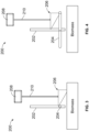
- FIGS. 3-4 and 5-6 illustrations showing a linear operation of the bed level sensor system of FIG. 1 and a rotational operation of the bed level sensor system of FIG. 2 are shown, respectively.
- the float 206 In a default position shown in FIGS. 3 and 5 , the float 206 is normally rested on top of the biomass due to gravity.
- the leveling arm 204 is configured to continuously rotate (e.g. counter-clockwise). For instance, an end of the leveling arm 204 is shown in FIGS. 3 and 5 aligned with the central rod 202 as the leveling arm 204 is in a first position, at the beginning of a rotation, immediately before contacting the float 206.
- the leveling arm 204 rotates counterclockwise, contact between the leveling arm 204 and the float 206 occurs due to rotation of the leveling arm 204.
- Displacement of the float 206 and the level sensor 208 may occur either rotationally or linearly.
- the float 206 is at a higher position due to the rotation of the leveling arm 204.
- the connector 210 may rotate due to the contact between the float 206 and the leveling arm 204.
- the rotational motion or the linear/vertical motion of the float 206 prevents the bed level sensor system 200 from being buried by as new biomass is added.
- the float 206 falls to rest back on the top of the biomass and the level sensor 208 provides a measurement of the biomass level, detected from the change between a starting position (e.g., a resting position before the leveling arm 204 passes) and an ending position (e.g., after the leveling arm 204 passes).
- a starting position e.g., a resting position before the leveling arm 204 passes
- an ending position e.g., after the leveling arm 204 passes.
- mechanical travel limits may be set for the float 206 and the level sensor 208 to prevent a situation where the biomass would bind with the leveling arm 204.
- the biochar production system 100 also includes a controller (not shown).
- the controller is communicatively coupled with the biochar production system 100 to control operation of the biochar production system 100.
- the controller determines, based on various characteristics (temperature in various locations, biomass temperature, biochar temperature, etc.), the rate at which biomass is introduced to the biochar production system 100 and the rate at which biochar is directed away from the biochar production system 100.
- the controller is configured to control operation of the bed level sensor system 200. For example, the controller may determine the solids bed level and perform various diagnostic checks.
- the controller may have provisions to ignore/omit data when the level sensor 208 is lifted, e.g. a band pass filter or ignoring times known to be associated with sensor lifting.
- FIGS. 7-9 flow diagrams illustrating a method for operating a bed level sensor system are shown according to a particular embodiment.
- FIG. 7 depicts a level sensor logic 700 for sensing and determining the solid bed level via a level sensor. Based on the bed level output from the level sensor logic, the level sensor logic feeds in the fixed input control logic of FIG. 8 or the fixed output control logic of FIG. 9 regarding how the gasifier feed is controlled.
- a leveling arm speed is determined.
- the leveling arm speed may be determined based upon from the entry of a user entry/input (701).
- the user entry may be indicative of a leveling arm speed of the leveling arm.
- the leveling arm speed 702 may be determined based on a calculation indicative of the leveling arm speed.
- the level sensor measurement at 703 may be sampled at a variable rate. As a bin (e.g., reactor body) fills, the frequency of the sensor lift may be increased to assure no overfills. As such, the leveling arm speed is calculated and adjusted (e.g., increased).
- a limit check is performed based on the arm speed (e.g., the input/determination at 702) and the limits of the bin volume (e.g., input at 705).
- the limit check and the set variable sample rate are both used as inputs in populating a data buffer in the lifting logic at 708.
- the logic 700 is configured to ignore/omit a sample reading when the reading is determined to be invalid.
- An invalid reading may include a sensor reading indicative of a maximum threshold reached.
- a diagnostic check is performed. For instance, after a predetermined amount of invalid samples is detected (e.g., an accumulated amount or consecutive number of invalid sample readings reaches a predetermined threshold) at 708, a diagnostic event (such as a warning) is generated, a sensor relevel is initiated, and/or a shutdown occurs if it is unresponsive. Accordingly, the level sensor logic 700 provides an input to the fixed input or output control logic 800 and 900, respectively, as 712.
- the bed level output 712 feeds into the proportional integral derivative control (PID Control) to maintain a particular bed level compared to a set point.
- PID Control proportional integral derivative control
- a diagnostic/limit check is performed. For instance, a fixed conveyer speed (e.g., the conveyer feed into the gasifier) is set by a user entry at 805. As such, the fixed conveyer speed at 805, the determined extraction speed (e.g. a system input) at 802, and at least one of a gas temperature limit set at 807, an auger speed limit set at 809, and an agitator torque limit set at 811 are used to determine if a limit is reached. If the limit is reached and held for a predetermined period of time (e.g., a predetermined number of seconds), the logic 800 is configured to generate a diagnostic warning, switch to the fixed output control logic, and/or implement a shutdown if there are continued limit violations.
- a predetermined period of time e.g., a predetermined number of seconds
- the bed level output 712 feeds into the proportional integral derivative control (PID Control) to maintain a particular bed level compared to a set point.
- PID Control proportional integral derivative control
- the bed level output e.g., at 712
- the logic 900 is configured to decrease a conveyer speed. If the bed level is less than the set point, the logic 900 is configured to increase the conveyer speed.
- a diagnostic/limit check is performed. For instance, a fixed extraction speed (e.g., the extraction of the biomass from the gasifier) is set by a user entry at 905. As such, the fixed extraction speed at 905, the determined conveyer speed (e.g. a system input) at 902, and at least one of a gas temperature limit set at 907, an auger speed limit set at 909, and an agitator torque limit set at 911 are used to determine if a limit is reached. If the limit is reached and held for a predetermined period of time (e.g., a predetermined number of seconds), the logic 900 is configured to generate a diagnostic warning, switch to the fixed input control logic, and/or implement a shutdown if there are continued limit violations.
- a predetermined period of time e.g., a predetermined number of seconds
- the bed level sensor described herein allows for better bed level control for the biochar reactor with a low cost, durable, reliable method of bed level sensing.
- Coupled means the joining or linking of two members directly or indirectly to one another. Such joining may be stationary or moveable in nature.
- a propeller shaft of an engine “coupled” to a transmission represents a moveable coupling. Such joining may be achieved with the two members or the two members and any additional intermediate members.
- the term "or” is used in its inclusive sense (and not in its exclusive sense) so that when used, for example, to connect a list of elements, the term “or” means one, some, or all of the elements in the list.
- Conjunctive language such as the phrase "at least one of X, Y, and Z," unless specifically stated otherwise, is otherwise understood with the context as used in general to convey that an item, term, etc. may be either X, Y, Z, X and Y, X and Z, Y and Z, or X, Y, and Z (i.e., any combination of X, Y, and Z).
- Conjunctive language is not generally intended to imply that certain embodiments require at least one of X, at least one of Y, and at least one of Z to each be present, unless otherwise indicated.
Landscapes
- Chemical & Material Sciences (AREA)
- Engineering & Computer Science (AREA)
- Oil, Petroleum & Natural Gas (AREA)
- Organic Chemistry (AREA)
- Materials Engineering (AREA)
- Physics & Mathematics (AREA)
- Chemical Kinetics & Catalysis (AREA)
- General Physics & Mathematics (AREA)
- Fluid Mechanics (AREA)
- Combustion & Propulsion (AREA)
- Thermal Sciences (AREA)
- General Chemical & Material Sciences (AREA)
- Apparatus Associated With Microorganisms And Enzymes (AREA)
- Processing Of Solid Wastes (AREA)
Abstract
Description
- This application claims the benefit and priority of
U.S. Provisional Patent Application 63/249,799, filed on September 29, 2021 to Pendray et al. - The present disclosure relates to the operation of a bed level sensor of biomass in an autothermal pyrolyzer system.
- Biochar is a substance that is produced by heating organic material from agricultural and forestry wastes (also called biomass) in a controlled, oxygen deficient process called pyrolysis. Biochar can be used, for example, as fuel, as a soil additive, for filtration purposes, and to store atmospheric carbon. During pyrolysis, the biomass is heated in a container with very little oxygen. As the biomass is heated, it releases pyrolytic gases and is eventually converted into biochar.
- To produce biochar in a biochar production system (e.g., an autothermal pyrolyzer, gasifier, etc.), biomass is introduced into a reactor top and moves downward through the reactor where it is heated to the point where the biomass is converted to biochar (i.e., to a pyrolysis temperature). The reaction also causes the biomass to release gases as it is converted to biochar. The gases exit the top of the biochar production system and can be used as fuel. The biochar exits the bottom of the biochar production system and can be used as fuel, as a soil additive, or for filtration purposes. The biochar can also be used to store atmospheric carbon.
- The gases released due to pyrolysis are often dewy and opaque, and it is difficult to use measuring techniques to determine a bed level, i.e., the level of biomass in the biochar production system. Without such a diagnostic, the system can run with too low or too high of a biomass level. For instance, when the reactor is too low, the gases coming out of the updraft reactor are excessively hot, leading to potential equipment failure. When biomass levels are too high, agitator jamming or excessive pressure loss across the gasifier may take place. Thus, an arm leveler is provided to detect the biomass level.
- One embodiment relates to a biochar production system. The biochar production system includes a reactor body, a leveling arm extending configured to move generally along a leveling place in the reactor body, and a bed level sensor system. The bed level sensor system includes a float configured to move from a resting position on biomass in the reactor to an ending position upon contact with the leveling arm, and a level sensor coupled to the float via a connector. The level sensor is configured to correspondingly move with the float. A controller is configured to detect bed levels of the biomass within the reactor body, and determine a plurality of sample readings based on the detected bed levels.
- Another embodiment provides for a method for selectively controlling a biochar production system. The method includes receiving an operating parameter value by a controller and the controller determines if the operating parameter value is greater than or meets a predetermined set point. The set point is based on a bin volume of a reactor body. The method further includes activating at least one of an extractor to direct more biochar out of the reactor body and activating a conveyer to direct less biomass into the reactor if the operating parameter value is greater than or meets the predetermined set point. The method also includes activating at least one of the extractor to direct less biochar out of the reactor body and activating the conveyer to direct more biomass into the reactor if the operating parameter value is less than the predetermined set point.
- Still another embodiment provides for a controller for a biochar production system. The controller is communicatively coupled to a bed level sensor that determines a bed level inside of a reactor body. The output of the bed level sensor is received by the controller. The controller is configured to determine a set point that is indicative of a desired bed level and determine if the output from the bed level sensor is greater than or equal to the set point. The controller is further configured to activate at least one of an extractor to direct more biochar out of the reactor body and activate a conveyer to direct less biomass into the reactor if the output is greater than or equal to the set point. The controller is configured to, if the output is not greater than or equal to the set point, activate at least one of the extractor to direct less biochar out of the reactor body and the conveyer to direct more biomass into the reactor.
-
-
FIG. 1 is an illustration of an exploded view of a biochar production system, according to an example embodiment. -
FIG. 2 is an illustration of a bed level sensor system for use in a biochar production system, according to a particular embodiment. -
FIGS. 3-4 are illustrations of a linear operation of the bed level sensor system ofFIG. 1 . -
FIGS. 5-6 are illustrations of a rotational operation of the bed level sensor system ofFIG. 1 . -
FIGS. 7-9 are flow diagram of an example method for operating a bed level sensor system, according to a particular embodiment. - Following below are more detailed descriptions of methods, apparatuses, and systems for a bed level sensor system. The methods, apparatuses, and systems introduced above and discussed in greater detail below may be implemented in any of numerous ways, as the described concepts are not limited to any particular manner of implementation. Examples of specific implementations and applications are provided primarily for illustrative purposes.
- As disclosed herein, a sensor is provided on the arm leveler to sense the bed level upon each sweeping pass. As such, a bed level detection solution is created in conjunction with the sweeping arm already present to reset the level. This can further improve uniformity of the gas flow through the bed.
- As is described further herein, the biomass level is sensed by a linear or potentially rotary position sensor that is lifted above the bed level periodically to ensure position at the top of the bed. The dry solids bed level sensor is lifted periodically by a bed leveling arm, where the linear position sensor is coupled to the bed leveling arm. In contrast, various alternative conventional bed level sensors for dry beds tend to be sensitive to the condensing environments that are present at the top of the reactor. For example, ultrasonic sensors are sensitive to condensation on the sensing component. Further, rotary motion sensors in contact with the biomass in various conventional systems can stick if they are subjected to condensing tars, and also don't work well with a bed leveling actuator. As such, the bed level sensor described herein allows for better bed level control for the biochar reactor with a low cost, durable, reliable method of bed level sensing.
- While embodiments described herein provide a system that can reliably sense bed level while providing variable control feedback, it should be understood that the description and Figures herein are not meant to be limiting. The systems described herein are also applicable to accomplish other effects.
- Referring now to
FIG. 1 , an illustration of an exploded view of abiochar production system 100 is shown, according to an example embodiment. Thebiochar production system 100 includes areactor body 102, anextraction body 104, aconduit manifold 106, anagitator 108, and atop portion 110. - The
reactor body 102 is generally cylindrical with a substantially circular cross-sectional shape, and includes anouter wall 152 and aninner wall 154. A plurality ofapertures 118 extend entirely through theouter wall 152 and theinner wall 154. For eachaperture 118, there is acorresponding aperture 118 positioned substantially across from therespective aperture 118 such that a component passing straight through theaperture 118 will also pass through thecorresponding aperture 118. - The
extraction body 104 is coupled with thereactor body 102 at the first end of thereactor body 102 and is shown to include anextraction cone 120, anoutlet 124, and anoutlet cap 126. Theextraction cone 120 comprises a generally hollow cone shape that is configured to direct biochar away from thereactor body 102 and out of thebiochar production system 100 through theoutlet 124. Theextraction body 104 defines aquench zone 122 configured to introduce a coolant (e.g., water) to the biochar to cool the biochar to a temperature below approximately one hundred degrees Celsius such that the biochar can be handled by an operator after the biochar exits thebiochar production system 100. - In some embodiments, the
extraction body 104 includes a metering device (not shown) to direct biochar out of theoutlet 124. For example, the metering device may include a rotatable augur that directs biochar out of theoutlet 124 as it rotates. The metering device may also include a conveyer system to direct biochar out of theoutlet 124. - The
conduit manifold 106 includes a plurality of conduits configured to interface with theapertures 118 of thereactor body 102 such that thereactor body 102 supports the plurality of conduits. Theconduit manifold 106 is configured to introduce air into thereactor body 102 via the plurality of conduits. - The
top portion 110 is coupled to the second end of thereactor body 102 and is configured to direct gases away from thereactor body 102. Thetop portion 110 is shown to include acover 134 and abearing 136. Thecover 134 comprises a generally circular shape that substantially matches the shape of the second end of thereactor body 102. Thebearing 136 is configured to interface with theagitator 108 to facilitate rotation of theagitator 108. In some embodiments, thecover 134 and thebearing 136 define a space therebetween through which gases from the biochar production process are directed. A pipe or other similar device (e.g., channel, tube, duct, etc.) may be coupled with the cover and extend from the space to direct the gases to another location for collection. - The
agitator 108 is coupled to thebearing 136 and is configured to disrupt the biomass in thereactor body 102. As shown, theagitator 108 includes arod 128, afirst protrusion 130, and asecond protrusion 132. Theagitator 108 may be coupled to a motor that causes therod 128 to rotate such that thefirst protrusion 130 and thesecond protrusion 132 contact the biomass as therod 128 rotates to disrupt the biomass located in thereactor body 102. - Referring now to
FIG. 2 , an illustration of a bedlevel sensor system 200 for use in a biochar production system is shown, according to a particular embodiment. The bedlevel sensor system 200 is configured to be used in thereactor body 102 of thebiochar production system 100, for instance. - The bed
level sensor system 200 includes a central rod 202 (e.g., therod 128 ofFIG. 1 ). Thecentral rod 202 may be disposed in a center of thereactor body 102. As shown inFIG. 1 , thereactor body 102 is generally cylindrical with a substantially circular cross-sectional shape such that thecentral rod 202 runs longitudinally through the center of thereactor body 102. The bedlevel sensor system 200 further includes a levelingarm 204. The levelingarm 204 extends radially from thecentral rod 202. The levelingarm 204 may extend from opposite sides of thecentral rod 202 such that thecentral rod 202 and the levelingarm 204 form a "T" configuration or a "+" configuration. - The
central rod 202 may be coupled to a bearing (e.g., the bearing 136) and a motor (not shown). The motor is configured to cause thecentral rod 202 to rotate such that the levelingarm 204 rotates about a central axis of thereactor body 102. In turn, the levelingarm 204 is configured to disrupt the biomass in the reactor. In alternative arrangements, however, a central rod may not be used. By way of example, the levelingarm 204 may use an end pivot or a linear motion chain-based device for rotation about the central axis. In still other embodiments, e.g., where thereactor body 102 does not possess a cylindrical shape, the levelingarm 204 may not rotate about the central axis. For example, the levelingarm 204 may move generally along a leveling place in thereactor body 102, e.g., via a reciprocating motion. - The bed
level sensor system 200 includes afloat 206. Thefloat 206 is configured to rise as the levelingarm 204 rotates and hits thefloat 206. After theleveling arm 204 passes, thefloat 206 is configured to fall and rest back on top of the biomass. The bedlevel sensor system 200 includes alevel sensor 208. Thelevel sensor 208 is coupled to thefloat 206 via aconnector 210. Theconnector 210 may be a rigid rod such that any movement of thefloat 206 translates to thelevel sensor 208. For instance, when thefloat 206 rises as the levelingarm 204 rotates and hits thefloat 206, thelevel sensor 208 correspondingly rises. After theleveling arm 204 passes and thefloat 206 falls, thelevel sensor 208 correspondingly falls. - The
level sensor 208 includes a linear position sensor, e.g. a variable resistance sensor similar to those present in fuel tank level sensors. By periodically lifting the bottom of thelevel sensor 208 via lifting thefloat 206 above the bed (e.g. 1-20 times per minute), the bedlevel sensor system 200 ensures that thelevel sensor 208 remains on top of the solids bed and does not move down into the bed. Retaining thelevel sensor 208 above the solids bed is accomplished as the solids bed is "raked" by the leveling arm 204 (e.g., a leveling device) that passes beneath thelevel sensor 208 and thefloat 206 of the biochar gasifier reactor. As will be described further herein, as thelevel sensor 208 settles, the bed level is detected by thelevel sensor 208. - Referring now to
FIGS. 3-4 and5-6 , illustrations showing a linear operation of the bed level sensor system ofFIG. 1 and a rotational operation of the bed level sensor system ofFIG. 2 are shown, respectively. In a default position shown inFIGS. 3 and5 , thefloat 206 is normally rested on top of the biomass due to gravity. The levelingarm 204 is configured to continuously rotate (e.g. counter-clockwise). For instance, an end of the levelingarm 204 is shown inFIGS. 3 and5 aligned with thecentral rod 202 as the levelingarm 204 is in a first position, at the beginning of a rotation, immediately before contacting thefloat 206. As such, as the levelingarm 204 rotates counterclockwise, contact between the levelingarm 204 and thefloat 206 occurs due to rotation of the levelingarm 204. Displacement of thefloat 206 and thelevel sensor 208 may occur either rotationally or linearly. For instance, as shown inFIG. 4 , thefloat 206 is at a higher position due to the rotation of the levelingarm 204. As shown inFIG. 6 , theconnector 210 may rotate due to the contact between thefloat 206 and the levelingarm 204. The rotational motion or the linear/vertical motion of thefloat 206 prevents the bedlevel sensor system 200 from being buried by as new biomass is added. - Once the leveling
arm 204 passes, thefloat 206 falls to rest back on the top of the biomass and thelevel sensor 208 provides a measurement of the biomass level, detected from the change between a starting position (e.g., a resting position before the levelingarm 204 passes) and an ending position (e.g., after theleveling arm 204 passes). In various embodiments, mechanical travel limits may be set for thefloat 206 and thelevel sensor 208 to prevent a situation where the biomass would bind with the levelingarm 204. - The
biochar production system 100 also includes a controller (not shown). The controller is communicatively coupled with thebiochar production system 100 to control operation of thebiochar production system 100. The controller determines, based on various characteristics (temperature in various locations, biomass temperature, biochar temperature, etc.), the rate at which biomass is introduced to thebiochar production system 100 and the rate at which biochar is directed away from thebiochar production system 100. Additionally, the controller is configured to control operation of the bedlevel sensor system 200. For example, the controller may determine the solids bed level and perform various diagnostic checks. In various embodiments, the controller may have provisions to ignore/omit data when thelevel sensor 208 is lifted, e.g. a band pass filter or ignoring times known to be associated with sensor lifting. - Referring now to
FIGS. 7-9 , flow diagrams illustrating a method for operating a bed level sensor system are shown according to a particular embodiment.FIG. 7 depicts alevel sensor logic 700 for sensing and determining the solid bed level via a level sensor. Based on the bed level output from the level sensor logic, the level sensor logic feeds in the fixed input control logic ofFIG. 8 or the fixed output control logic ofFIG. 9 regarding how the gasifier feed is controlled. - Referring again to
FIG. 7 , examplelevel sensor logic 700 is described in detail. At 702, a leveling arm speed is determined. The leveling arm speed may be determined based upon from the entry of a user entry/input (701). The user entry may be indicative of a leveling arm speed of the leveling arm. Alternatively, the levelingarm speed 702 may be determined based on a calculation indicative of the leveling arm speed. For instance, at 704, the level sensor measurement at 703 may be sampled at a variable rate. As a bin (e.g., reactor body) fills, the frequency of the sensor lift may be increased to assure no overfills. As such, the leveling arm speed is calculated and adjusted (e.g., increased). At 706, a limit check is performed based on the arm speed (e.g., the input/determination at 702) and the limits of the bin volume (e.g., input at 705). The limit check and the set variable sample rate are both used as inputs in populating a data buffer in the lifting logic at 708. Particularly, at 708, if the level sensor is being raised at a known timing or the level sensor is reading out of range, the sample is to be removed. For instance, thelogic 700 is configured to ignore/omit a sample reading when the reading is determined to be invalid. An invalid reading may include a sensor reading indicative of a maximum threshold reached. For example, if a physical limiter for sensor height is not present and the sensor is only valid up to a height limit, data above that limit caused by lifting from the bed leveling arm would be omitted. At 710, a diagnostic check is performed. For instance, after a predetermined amount of invalid samples is detected (e.g., an accumulated amount or consecutive number of invalid sample readings reaches a predetermined threshold) at 708, a diagnostic event (such as a warning) is generated, a sensor relevel is initiated, and/or a shutdown occurs if it is unresponsive. Accordingly, thelevel sensor logic 700 provides an input to the fixed input oroutput control logic - Referring now to
FIG. 8 , the fixedinput control 800 is described in detail. The bed level output 712 (e.g. an operating parameter value) feeds into the proportional integral derivative control (PID Control) to maintain a particular bed level compared to a set point. For instance, at 802, the bed level output (e.g., at 712) of thelevel sensor logic 700 and one of a bed level set point based on a user entry at 801 or a calculated set point based on the bin volume at 803 factor into the PID control. If the bed level as detected by the level sensor is greater than or meets the set point, thelogic 800 is configured to increase an extraction speed. If the bed level is less than the set point, thelogic 800 is configured to decrease the extraction speed. At 804, a diagnostic/limit check is performed. For instance, a fixed conveyer speed (e.g., the conveyer feed into the gasifier) is set by a user entry at 805. As such, the fixed conveyer speed at 805, the determined extraction speed (e.g. a system input) at 802, and at least one of a gas temperature limit set at 807, an auger speed limit set at 809, and an agitator torque limit set at 811 are used to determine if a limit is reached. If the limit is reached and held for a predetermined period of time (e.g., a predetermined number of seconds), thelogic 800 is configured to generate a diagnostic warning, switch to the fixed output control logic, and/or implement a shutdown if there are continued limit violations. - Referring now to
FIG. 9 , the fixedoutput control 900 is described in detail. The bed level output 712 (e.g. an operating parameter) feeds into the proportional integral derivative control (PID Control) to maintain a particular bed level compared to a set point. For instance, at 902, the bed level output (e.g., at 712) of thelevel sensor logic 700 and one of a bed level set point based on a user entry at 901 or a calculated set point based on the bin volume at 903 factor into the PID control. If the bed level as detected by the level sensor is greater than the set point, thelogic 900 is configured to decrease a conveyer speed. If the bed level is less than the set point, thelogic 900 is configured to increase the conveyer speed. At 904, a diagnostic/limit check is performed. For instance, a fixed extraction speed (e.g., the extraction of the biomass from the gasifier) is set by a user entry at 905. As such, the fixed extraction speed at 905, the determined conveyer speed (e.g. a system input) at 902, and at least one of a gas temperature limit set at 907, an auger speed limit set at 909, and an agitator torque limit set at 911 are used to determine if a limit is reached. If the limit is reached and held for a predetermined period of time (e.g., a predetermined number of seconds), thelogic 900 is configured to generate a diagnostic warning, switch to the fixed input control logic, and/or implement a shutdown if there are continued limit violations. - As such, a system for reliably sensing bed level while providing variable control feedback is provided. The bed level sensor described herein allows for better bed level control for the biochar reactor with a low cost, durable, reliable method of bed level sensing.
- For the purpose of this disclosure, the term "coupled" means the joining or linking of two members directly or indirectly to one another. Such joining may be stationary or moveable in nature. For example, a propeller shaft of an engine "coupled" to a transmission represents a moveable coupling. Such joining may be achieved with the two members or the two members and any additional intermediate members.
- Although the diagrams herein may show a specific order and composition of method steps, the order of these steps may differ from what is depicted. For example, two or more steps may be performed concurrently or with partial concurrence. Also, some method steps that are performed as discrete steps may be combined, steps being performed as a combined step may be separated into discrete steps, the sequence of certain processes may be reversed or otherwise varied, and the nature or number of discrete processes may be altered or varied. The order or sequence of any element or apparatus may be varied or substituted according to alternative embodiments. All such modifications are intended to be included within the scope of the present disclosure as defined in the appended claims. Such variations will depend on the machine-readable media and hardware systems chosen and on designer choice. All such variations are within the scope of the disclosure.
- The foregoing description of embodiments has been presented for purposes of illustration and description. It is not intended to be exhaustive or to limit the disclosure to the precise form disclosed, and modifications and variations are possible in light of the above teachings or may be acquired from this disclosure. The embodiments were chosen and described in order to explain the principles of the disclosure and its practical application to enable one skilled in the art to utilize the various embodiments and with various modifications as are suited to the particular use contemplated. Other substitutions, modifications, changes and omissions may be made in the design, operating conditions and arrangement of the embodiments without departing from the scope of the present disclosure as expressed in the appended claims.
- Accordingly, the present disclosure may be embodied in other specific forms without departing from its spirit or essential characteristics. The described embodiments are to be considered in all respects only as illustrative and not restrictive. The scope of the disclosure is, therefore, indicated by the appended claims rather than by the foregoing description. All changes which come within the meaning and range of equivalency of the claims are to be embraced within their scope.
- Also, the term "or" is used in its inclusive sense (and not in its exclusive sense) so that when used, for example, to connect a list of elements, the term "or" means one, some, or all of the elements in the list. Conjunctive language such as the phrase "at least one of X, Y, and Z," unless specifically stated otherwise, is otherwise understood with the context as used in general to convey that an item, term, etc. may be either X, Y, Z, X and Y, X and Z, Y and Z, or X, Y, and Z (i.e., any combination of X, Y, and Z). Thus, such conjunctive language is not generally intended to imply that certain embodiments require at least one of X, at least one of Y, and at least one of Z to each be present, unless otherwise indicated.
Claims (16)
- A biochar production system comprising:a reactor body;a leveling arm configured to move along a leveling place in the reactor body;a bed level sensor system comprising:a float configured to move from a resting position on a biomass in the reactor to an ending position upon contact with the leveling arm; anda level sensor coupled to the float via a connector, the level sensor configured to correspondingly move with the float; anda controller configured to:detect bed levels of the biomass within the reactor body; anddetermine a plurality of sample readings based on the detected bed levels.
- The biochar production system of claim 1, wherein the controller is further configured to:omit invalid sample readings of the plurality of sample readings;determine an accumulated amount of invalid sample readings reaches a predetermined threshold; andgenerate a diagnostic event in response to the accumulated amount of invalid sample readings reaching the predetermined threshold or to:
determine a variable sample rate based on the detected bed levels and set the leveling arm speed such that as the bed levels increase in the reactor, the leveling arm speed is compensated so as to adjust the lift frequency of the level sensor to prevent overfill, or to:
increase an extraction speed to direct biochar out of an outlet of the reactor in response to the bed level being greater than a predetermined set point, or to:
decrease a conveyer speed to direct biomass into the reactor in response to the bed level being greater than a predetermined set point.. - The biochar production system of claim 2, wherein when the controller is configured to determine a variable sample rate, the controller is further configured to determine at least one of the leveling arm speed and a volume of the reactor.
- The biochar production system of claim 2, wherein when the controller is configured to increase an extraction speed, the controller is further configured to decrease the extraction speed to direct biochar out of an outlet of the reactor in response to the bed level being less than the predetermined set point.
- The biochar production system of claim 2, wherein when the controller is configured to decrease a conveyer speed, the controller is further configured to increase the conveyer speed to direct biomass into the reactor in response to the bed level being less than the predetermined set point.
- The biochar production system of claim 1, further comprising a central rod disposed within the reactor body, and wherein the leveling arm extends from the central rod.
- A method of selectively controlling a biochar production system, the method comprising:receiving by a controller of the biochar production system, an operating parameter value, the operating parameter value determined by a bed level sensor system;determining by the controller, whether the operating parameter value is greater than or meets a predetermined set point based on a bin volume of the reactor body;responsive to determining the operating parameter value is greater than or meets the predetermined set point, activating at least one of (a) an extractor to direct more biochar out of the reactor body and (b) a conveyer to direct less biomass into the reactor of the biochar production system to maintain a target operating parameter value;responsive to determining the operating parameter value is less than the predetermined set point, activating at least one of (a) the extractor to direct less biochar out of the reactor body and (b) the conveyer to direct more biomass into the reactor of the biochar production system to maintain the target operating parameter value.
- The method of claim 7, wherein the controller comprises:a fixed input controller communicatively coupled to the bed level sensor system, the fixed input controller configured to:receive the operating parameter value, the operating parameter value being indicative of a bed level, andresponsive to receiving the operating parameter value, select an extraction speed based on the bed level to direct biochar out of the reactor body; anda fixed output controller communicatively coupled to the bed level sensor system, the fixed output controller configured to:receive the operating parameter value, andselect a conveyer speed based on the operating parameter value to direct biomass into the reactor.
- The method of claim 8, wherein the operating parameter value is indicative of a bed level of the biochar production system, and further comprising:responsive to determining that the bed level is greater than or meets the predetermined set point, increasing the extraction speed to direct biochar out of an outlet of the reactor of the biochar production system to maintain the target bed level, orwherein the operating parameter is indicative of a bed level of the biochar production system, and further comprising:
responsive to determining that the bed level is less than the predetermined set point, decreasing the extraction speed to direct biochar out of an outlet of the reactor of the biochar production system to maintain a target bed level, orwherein the operating parameter is indicative of a bed level of the biochar production system, and further comprising:responsive to determining that the bed level is greater than or meets the predetermined set point, decreasing the conveyer speed to direct biomass into the reactor of the biochar production system to maintain the target bed level, orwherein the operating parameter is a bed level of the biochar production system, and further comprising:
responsive to determining that the bed level is less than the predetermined set point, increasing the conveyer speed to direct biomass into the reactor of the biochar production system to maintain the target bed level. - The method of claim 8, wherein the fixed input controller is communicatively coupled to one or more operating sensors, and wherein the fixed input controller further comprises a limit check configured to:
responsive to a system input reaching a limit for a threshold period of time:generate an extractor warning signal, andperform one of (a) activating the fixed output controller and (b) initiating a system shutdown. - The method of claim 10, wherein the system input is selected from the group consisting of an extraction speed, a gas temperature, an auger speed, an agitator torque, or a conveyer speed.
- The method of claim 8, wherein the fixed output controller is communicatively coupled to one or more operating sensors, and wherein the fixed output controller further comprises a limit check configured to:
responsive to a system input reaching a limit for a threshold period of time:generate a conveyer warning signal, andperform one of (a) activating the fixed input controller and (b) initiating a system shutdown. - A controller communicatively coupled to a sensor of a biochar production system, the controller configured to:receive an output from a bed level sensor, the bed level sensor configured to determine a bed level in a reactor body;determine a set point indicative of a desired bed level;determine whether the output from the bed level sensor is greater than or equal to the set point;responsive to determining the output is greater than or equal to the set point, activate at least one of (a) an extractor to direct more biochar out of the reactor body and (b) a conveyer to direct less biomass into the reactor of the biochar production system to maintain a target operating parameter value;responsive to determining the output is not greater than or equal to the set point, activate at least one of (a) the extractor to direct less biochar out of the reactor body and (b) the conveyer to direct more biomass into the reactor of the biochar production system to maintain the target operating parameter.
- The controller of claim 13, wherein the controller is configured to determine the set point is a user entry of the desired bed level, or
wherein the controller is configured to determine the set point is a calculated bed level based on a bin volume. - The controller of claim 13, further comprising:a fixed input control configured to:direct biochar out of an outlet of the reactor of the biochar production system at a fixed conveyer speed and an extraction speed,responsive to determining the output is greater than or meets the set point, increase the extraction speed, andresponsive to determining the output is less than the predetermined set point, decrease the extraction speed; anda fixed output control configured to:direct biomass into the reactor of a biochar production system at a fixed extraction speed and a variable conveyer speed,responsive to determining the output is greater than or meets the set point, decrease the variable conveyer speed, andresponsive to determining the output is less than the set point, increase the variable conveyer speed.
- The controller of claim 13, further comprising a limit check communicatively coupled to one or more operating sensors, the limit check configured to:receive one or more operating characteristics of the biochar production system, the one or more operating characteristics detected by the one or more operating sensors, the one or more operating sensors configured to determine at least one of a gas temperature, and auger speed, and an agitator;responsive to an input limit being reached for a threshold period of time, generate an input diagnostic warning and perform one of (a) activate the fixed output control and (b) initiate a system shutdown;responsive to an output limit being reached for the threshold period of time, generate an output limit diagnostic warning and perform one of (a) activate the fixed input control and (b) initiate a system shutdown.
Applications Claiming Priority (1)
| Application Number | Priority Date | Filing Date | Title |
|---|---|---|---|
| US202163249799P | 2021-09-29 | 2021-09-29 |
Publications (1)
| Publication Number | Publication Date |
|---|---|
| EP4159306A1 true EP4159306A1 (en) | 2023-04-05 |
Family
ID=83506045
Family Applications (1)
| Application Number | Title | Priority Date | Filing Date |
|---|---|---|---|
| EP22198287.9A Pending EP4159306A1 (en) | 2021-09-29 | 2022-09-28 | Solid bed level sensor for a biochar production system with a leveling actuator |
Country Status (2)
| Country | Link |
|---|---|
| US (1) | US12343718B2 (en) |
| EP (1) | EP4159306A1 (en) |
Families Citing this family (2)
| Publication number | Priority date | Publication date | Assignee | Title |
|---|---|---|---|---|
| EP4337605A4 (en) * | 2021-05-14 | 2025-03-26 | Cummins, Inc. | Enhancements for low cost autothermal pyrolyzer |
| CN121819731A (en) * | 2026-03-10 | 2026-04-10 | 辽宁津田科技有限公司 | Suspending agent production and allocation reaction kettle |
Citations (5)
| Publication number | Priority date | Publication date | Assignee | Title |
|---|---|---|---|---|
| US3110420A (en) * | 1961-08-30 | 1963-11-12 | Wilson Products Inc | Control means for solid dispensing apparatus |
| US3253745A (en) * | 1964-11-12 | 1966-05-31 | Mix Mill Inc | Delay control switch and hopper for feeding finely divided materials |
| US4659340A (en) * | 1985-06-24 | 1987-04-21 | Weaver Lloyd E | Pressurized downdraft gasifier |
| US5226927A (en) * | 1991-02-13 | 1993-07-13 | Southern California Edison | Wood gasifier |
| WO2019132466A1 (en) * | 2017-12-26 | 2019-07-04 | 주식회사 포스코 | Coal charge level control apparatus and method |
Family Cites Families (11)
| Publication number | Priority date | Publication date | Assignee | Title |
|---|---|---|---|---|
| US1941130A (en) * | 1933-12-26 | Coal distillation and coke produc | ||
| US4225392A (en) * | 1978-09-05 | 1980-09-30 | Taylor Leland T | Pyrolysis apparatus |
| DE3245567C2 (en) | 1982-12-09 | 1985-04-18 | Metallgesellschaft Ag, 6000 Frankfurt | Process for gasifying carbonaceous agglomerates in a fixed bed |
| US4968325A (en) * | 1987-08-24 | 1990-11-06 | Centre Quebecois De Valorisation De La Biomasse | Fluidized bed gasifier |
| US8317886B2 (en) * | 2002-05-22 | 2012-11-27 | Nexterra Systems Corp. | Apparatus and method for gasifying solid organic materials |
| US6993967B2 (en) * | 2002-07-12 | 2006-02-07 | Ti Group Automotive Systems, L.L.C. | Fluid level sensor |
| US8845769B2 (en) * | 2010-01-19 | 2014-09-30 | Zeropoint Clean Tech, Inc. | Downdraft gasifier with improved stability |
| US9009001B2 (en) * | 2011-05-26 | 2015-04-14 | Honeywell International Inc. | Monitoring for invalid data from field instruments |
| EP3041918A4 (en) | 2013-09-05 | 2017-08-30 | AG Energy Solutions, Inc. | Apparatuses, systems, mobile gasification systems, and methods for gasifying residual biomass |
| US11060032B2 (en) * | 2015-01-02 | 2021-07-13 | Suncoke Technology And Development Llc | Integrated coke plant automation and optimization using advanced control and optimization techniques |
| US11339342B2 (en) | 2017-05-16 | 2022-05-24 | Massachusetts Institute Of Technology | Biomass conversion reactors and associated systems and methods |
-
2022
- 2022-09-20 US US17/948,507 patent/US12343718B2/en active Active
- 2022-09-28 EP EP22198287.9A patent/EP4159306A1/en active Pending
Patent Citations (5)
| Publication number | Priority date | Publication date | Assignee | Title |
|---|---|---|---|---|
| US3110420A (en) * | 1961-08-30 | 1963-11-12 | Wilson Products Inc | Control means for solid dispensing apparatus |
| US3253745A (en) * | 1964-11-12 | 1966-05-31 | Mix Mill Inc | Delay control switch and hopper for feeding finely divided materials |
| US4659340A (en) * | 1985-06-24 | 1987-04-21 | Weaver Lloyd E | Pressurized downdraft gasifier |
| US5226927A (en) * | 1991-02-13 | 1993-07-13 | Southern California Edison | Wood gasifier |
| WO2019132466A1 (en) * | 2017-12-26 | 2019-07-04 | 주식회사 포스코 | Coal charge level control apparatus and method |
Also Published As
| Publication number | Publication date |
|---|---|
| US20230103111A1 (en) | 2023-03-30 |
| US12343718B2 (en) | 2025-07-01 |
Similar Documents
| Publication | Publication Date | Title |
|---|---|---|
| US12343718B2 (en) | Bed level sensor for solid beds with leveling actuators | |
| US4225392A (en) | Pyrolysis apparatus | |
| CN102449461B (en) | Device for measuring the loss on ignition and thermal decomposition reaction of solid particles in automatic pipeline | |
| JP6402419B2 (en) | Method and device for gasifying a feedstock | |
| Shaha | Combustion engineering and fuel technology | |
| US6843103B2 (en) | Automatic system for collecting, weighing and releasing solid particles | |
| RU2559491C2 (en) | Method and device for biomass low-temperature pyrolysis | |
| WO2016037124A1 (en) | Apparatuses, systems, staging hoppers, and methods for controlling continuous feed of feedstock to a gasifier | |
| EP4339263A1 (en) | Waste to energy system and process for solid waste feedstock | |
| US12600910B2 (en) | Updraft gasifier and method, apparatus, and system for biomass decomposition | |
| CN113531556A (en) | Control method of self-maintaining smoldering treatment system for high-water-content sludge | |
| CN105542812A (en) | Continuous biomass pyrolysis device and temperature monitoring control method thereof | |
| CN112625719B (en) | System and method for recovering oil product by continuous multi-stage pyrolysis of oily sludge | |
| CN112574765B (en) | Material level control method and device for cracking equipment and cracking equipment | |
| US20130276515A1 (en) | Measuring device for dust in flue gas | |
| CN205313461U (en) | Continuous biomass pyrolysis device | |
| JP2009235141A (en) | Biomass gasification apparatus | |
| JP2005274502A (en) | Evaluation method of trapping amount in trapping material | |
| JP2008196805A (en) | Temperature measuring device | |
| CN207362140U (en) | A kind of continuous carbonization device | |
| KR101198892B1 (en) | Device for charging coal of charging car in coke oven | |
| CN221199597U (en) | A gas detection system for granaries | |
| KR840001454B1 (en) | Improvements relating to furances | |
| CN118311210B (en) | Application method of boiler oxygen field dynamic measurement system | |
| CN207175860U (en) | Revolution pyrolysis oven charing insulation is with sealing charcoal system |
Legal Events
| Date | Code | Title | Description |
|---|---|---|---|
| PUAI | Public reference made under article 153(3) epc to a published international application that has entered the european phase |
Free format text: ORIGINAL CODE: 0009012 |
|
| STAA | Information on the status of an ep patent application or granted ep patent |
Free format text: STATUS: THE APPLICATION HAS BEEN PUBLISHED |
|
| AK | Designated contracting states |
Kind code of ref document: A1 Designated state(s): AL AT BE BG CH CY CZ DE DK EE ES FI FR GB GR HR HU IE IS IT LI LT LU LV MC MK MT NL NO PL PT RO RS SE SI SK SM TR |
|
| P01 | Opt-out of the competence of the unified patent court (upc) registered |
Effective date: 20230510 |
|
| STAA | Information on the status of an ep patent application or granted ep patent |
Free format text: STATUS: REQUEST FOR EXAMINATION WAS MADE |
|
| 17P | Request for examination filed |
Effective date: 20230718 |
|
| RBV | Designated contracting states (corrected) |
Designated state(s): AL AT BE BG CH CY CZ DE DK EE ES FI FR GB GR HR HU IE IS IT LI LT LU LV MC MK MT NL NO PL PT RO RS SE SI SK SM TR |