EP4159127A1 - Automatic detection of the his bundle during electrophysiological mapping - Google Patents
Automatic detection of the his bundle during electrophysiological mapping Download PDFInfo
- Publication number
- EP4159127A1 EP4159127A1 EP22196751.6A EP22196751A EP4159127A1 EP 4159127 A1 EP4159127 A1 EP 4159127A1 EP 22196751 A EP22196751 A EP 22196751A EP 4159127 A1 EP4159127 A1 EP 4159127A1
- Authority
- EP
- European Patent Office
- Prior art keywords
- peaks
- locations
- iegm
- signals
- time
- Prior art date
- Legal status (The legal status is an assumption and is not a legal conclusion. Google has not performed a legal analysis and makes no representation as to the accuracy of the status listed.)
- Granted
Links
Images


Classifications
-
- A—HUMAN NECESSITIES
- A61—MEDICAL OR VETERINARY SCIENCE; HYGIENE
- A61B—DIAGNOSIS; SURGERY; IDENTIFICATION
- A61B5/00—Measuring for diagnostic purposes; Identification of persons
- A61B5/24—Detecting, measuring or recording bioelectric or biomagnetic signals of the body or parts thereof
- A61B5/316—Modalities, i.e. specific diagnostic methods
- A61B5/318—Heart-related electrical modalities, e.g. electrocardiography [ECG]
- A61B5/367—Electrophysiological study [EPS], e.g. electrical activation mapping or electro-anatomical mapping
-
- A—HUMAN NECESSITIES
- A61—MEDICAL OR VETERINARY SCIENCE; HYGIENE
- A61B—DIAGNOSIS; SURGERY; IDENTIFICATION
- A61B5/00—Measuring for diagnostic purposes; Identification of persons
- A61B5/24—Detecting, measuring or recording bioelectric or biomagnetic signals of the body or parts thereof
- A61B5/316—Modalities, i.e. specific diagnostic methods
- A61B5/318—Heart-related electrical modalities, e.g. electrocardiography [ECG]
- A61B5/346—Analysis of electrocardiograms
- A61B5/349—Detecting specific parameters of the electrocardiograph cycle
-
- A—HUMAN NECESSITIES
- A61—MEDICAL OR VETERINARY SCIENCE; HYGIENE
- A61B—DIAGNOSIS; SURGERY; IDENTIFICATION
- A61B5/00—Measuring for diagnostic purposes; Identification of persons
- A61B5/06—Devices, other than using radiation, for detecting or locating foreign bodies ; Determining position of diagnostic devices within or on the body of the patient
- A61B5/061—Determining position of a probe within the body employing means separate from the probe, e.g. sensing internal probe position employing impedance electrodes on the surface of the body
-
- A—HUMAN NECESSITIES
- A61—MEDICAL OR VETERINARY SCIENCE; HYGIENE
- A61B—DIAGNOSIS; SURGERY; IDENTIFICATION
- A61B5/00—Measuring for diagnostic purposes; Identification of persons
- A61B5/24—Detecting, measuring or recording bioelectric or biomagnetic signals of the body or parts thereof
- A61B5/25—Bioelectric electrodes therefor
- A61B5/279—Bioelectric electrodes therefor specially adapted for particular uses
- A61B5/28—Bioelectric electrodes therefor specially adapted for particular uses for electrocardiography [ECG]
- A61B5/283—Invasive
-
- A—HUMAN NECESSITIES
- A61—MEDICAL OR VETERINARY SCIENCE; HYGIENE
- A61B—DIAGNOSIS; SURGERY; IDENTIFICATION
- A61B5/00—Measuring for diagnostic purposes; Identification of persons
- A61B5/24—Detecting, measuring or recording bioelectric or biomagnetic signals of the body or parts thereof
- A61B5/25—Bioelectric electrodes therefor
- A61B5/279—Bioelectric electrodes therefor specially adapted for particular uses
- A61B5/28—Bioelectric electrodes therefor specially adapted for particular uses for electrocardiography [ECG]
- A61B5/283—Invasive
- A61B5/287—Holders for multiple electrodes, e.g. electrode catheters for electrophysiological study [EPS]
-
- A—HUMAN NECESSITIES
- A61—MEDICAL OR VETERINARY SCIENCE; HYGIENE
- A61B—DIAGNOSIS; SURGERY; IDENTIFICATION
- A61B5/00—Measuring for diagnostic purposes; Identification of persons
- A61B5/24—Detecting, measuring or recording bioelectric or biomagnetic signals of the body or parts thereof
- A61B5/316—Modalities, i.e. specific diagnostic methods
- A61B5/318—Heart-related electrical modalities, e.g. electrocardiography [ECG]
- A61B5/346—Analysis of electrocardiograms
- A61B5/347—Detecting the frequency distribution of signals
-
- A—HUMAN NECESSITIES
- A61—MEDICAL OR VETERINARY SCIENCE; HYGIENE
- A61B—DIAGNOSIS; SURGERY; IDENTIFICATION
- A61B5/00—Measuring for diagnostic purposes; Identification of persons
- A61B5/72—Signal processing specially adapted for physiological signals or for diagnostic purposes
- A61B5/7235—Details of waveform analysis
- A61B5/7246—Details of waveform analysis using correlation, e.g. template matching or determination of similarity
-
- A—HUMAN NECESSITIES
- A61—MEDICAL OR VETERINARY SCIENCE; HYGIENE
- A61B—DIAGNOSIS; SURGERY; IDENTIFICATION
- A61B5/00—Measuring for diagnostic purposes; Identification of persons
- A61B5/72—Signal processing specially adapted for physiological signals or for diagnostic purposes
- A61B5/7235—Details of waveform analysis
- A61B5/725—Details of waveform analysis using specific filters therefor, e.g. Kalman or adaptive filters
-
- A—HUMAN NECESSITIES
- A61—MEDICAL OR VETERINARY SCIENCE; HYGIENE
- A61B—DIAGNOSIS; SURGERY; IDENTIFICATION
- A61B5/00—Measuring for diagnostic purposes; Identification of persons
- A61B5/72—Signal processing specially adapted for physiological signals or for diagnostic purposes
- A61B5/7235—Details of waveform analysis
- A61B5/7264—Classification of physiological signals or data, e.g. using neural networks, statistical classifiers, expert systems or fuzzy systems
-
- A—HUMAN NECESSITIES
- A61—MEDICAL OR VETERINARY SCIENCE; HYGIENE
- A61B—DIAGNOSIS; SURGERY; IDENTIFICATION
- A61B5/00—Measuring for diagnostic purposes; Identification of persons
- A61B5/74—Details of notification to user or communication with user or patient; User input means
- A61B5/742—Details of notification to user or communication with user or patient; User input means using visual displays
- A61B5/743—Displaying an image simultaneously with additional graphical information, e.g. symbols, charts, function plots
-
- A—HUMAN NECESSITIES
- A61—MEDICAL OR VETERINARY SCIENCE; HYGIENE
- A61B—DIAGNOSIS; SURGERY; IDENTIFICATION
- A61B2505/00—Evaluating, monitoring or diagnosing in the context of a particular type of medical care
- A61B2505/05—Surgical care
Definitions
- the present invention relates generally to electrophysiological (EP) mapping, and particularly to detection of the His bundle by EP mapping and to visualization of the detected His bundle on an EP map.
- EP electrophysiological
- U.S. Patent No. 10,285,647 describes a method and system for assigning map points to anatomical segments of a heart.
- the method and system utilize an intravascular mapping tool configured to be inserted into at least one of the endocardial or epicardial space.
- the mapping tool is maneuvered to select locations proximate to surfaces of the heart, while collecting map points at the select locations to form a ROI data set.
- the method and system store the ROI data set in a data storage means and defines apical, basal and circumferential landmarks within the ROI data set.
- the method and system automatically calculate circumferential and longitudinal segment boundaries, associated with wall segments of the heart, based on the apical, basal and circumferential landmarks.
- the method and system automatically assign segment identifiers (IDs) to the map points based on locations of the map points relative to the circumferential and longitudinal boundaries, the segment IDs associated with wall segments of the heart.
- IDs segment identifiers
- a septal landmark can be used by detecting a His bundle potential along the right ventricle (RV) septum that would indicate the circumferential location of the septal wall.
- International Patent Application Publication WO 2021/078,848 describes an implantable medical device for stimulating a heart, the device comprising a housing, a processor, a memory unit, a stimulation unit configured to stimulate the His bundle of the heart, and a detection unit configured to detect an electrical signal at the His bundle of the same heart.
- An embodiment of the present invention that is described hereinafter provides a method including receiving intracardiac electrogram (IEGM) signals measured at a plurality of locations in a region of a heart that contains a His bundle of the heart.
- the IEGM signals are processed to find respective local activation time (LAT) values at the plurality of the locations.
- LAT local activation time
- a cluster of the locations is identified at which peaks in the IEGM signals, associated with the LAT values, occur later than a defined time.
- respective time differences are calculated between times of occurrence of the identified peaks and a reference time. The time differences are compared to a threshold value and retained are the locations for which the time differences are below the threshold value.
- the IEGM signals measured at the retained locations are filtered to identify respective high-frequency peaks in the IEGM signals.
- the identified high-frequency peaks are cross corelated to identify a subset of the locations whose high-frequency peaks meet a predefined cross-correlation level.
- the high-frequency peaks are tagged as His peaks, and indicated on a cardiac map.
- indicating the tagged His peaks includes coloring a His region on the map.
- identifying the cluster includes applying a clustering algorithm.
- the reference time is an end time of a window of interest (WOI) provided by a user.
- WI window of interest
- filtering the signals includes passing each of the IEGM signals through a high pass filter.
- the IEGMs are acquired using a mapping catheter positioned in a cardiac chamber.
- EP electrophysiological
- cardiac arrhythmia may be manifested in episodes of irregular EP signals, such as irregular intracardiac electrograms (IEGMs).
- IEGMs irregular intracardiac electrograms
- a multi-electrode catheter may be used to acquire IEGMs to detect a cardiac tissue location causing the irregular IEGMs. After mapping, a physician may ablate detected arrhythmogenic tissue. Often, to generate an accurate EP map of cardiac tissue, a physician may be required to pace the heart from a certain tissue location inside the heart, such as from a vicinity of the His bundle.
- Catheter-based EP mapping techniques can produce various types of EP maps of a cardiac chamber, such as the left atrium of a heart.
- cardiac EP maps such as a local activation time (LAT) map, a bipolar potential map, or a unipolar potential map, are produced by acquiring IEGMs from locations on a heart chamber surface.
- EP values such as LATs (or potentials) are then derived from the IEGMs for the locations.
- Such locations and respective EP values called hereafter "data points,” are then overlayed, typically as a color, onto a 3D map of the chamber.
- the His bundle is part of the Purkinje fibers in the heart, located between the heart chambers.
- the His bundle is a good place from which to pace, though this area should be avoided for ablation. Therefore, it is important to identify the His bundle on the EP map, e.g., by using a tag.
- the His bundle is difficult to identify from IEGMs captured in the atrium, as the identifying peak in the electrical signal is very small because the His bundle, which is primarily located in the ventricle, is itself also very small. Therefore, in order to detect a peak that identifies the His bundle, a catheter with many small electrodes is needed to capture accurate signals. Small electrodes for accuracy of the signals, and many electrodes to make sure that the catheter has a good chance of having some of its electrodes in the region of the His bundle. It is still very difficult for a physician to detect the His bundle from the IEGMs, due to the very small peak and the many IEGM signals to examine per catheter position.
- Embodiments of the present invention that are described hereinafter provide an automatic His bundledetection algorithm that is based on IEGMs collected by a multi-electrode catheter (e.g., a multi-arm catheter or a basket catheter), a created LAT map, and a window of interest (WOI) defined by the physician according to the atrial mapping of the atrium.
- a multi-electrode catheter e.g., a multi-arm catheter or a basket catheter
- WOI window of interest
- the disclosed algorithm relies on the fact that the peak due to the His bundle generally appears very late in the WOI, and is seen on a LAT map as a late activation color-coded region, as shown below.
- the His bundle is also generally surrounded by a tissue area that produces relatively early activations. It should be noted that such a region of late activation on the LAT map does not always mean that the region is the His bundle. Instead, it indicates that the region is a candidate for being considered as the His bundle, subject to further tests described below.
- the disclosed method to detect the His bundle therefore includes the following algorithm steps:
- a system in an exemplary embodiment, includes an interface and a processor.
- the interface is configured to receive intracardiac electrogram (IEGM) signals measured at a plurality of locations in a region of a heart that contains a His bundle of the heart.
- the processor processes the IEGM signals to find respective local activation time (LAT) values at the plurality of the locations.
- LAT local activation time
- the processor identifies a cluster of the locations at which peaks in the IEGM signals, associated with the LAT values, occur later than a defined time. For the locations in the identified cluster, the processor calculates respective time differences between times of occurrence of the identified peaks and a reference time. Next, the processor compares the time differences to a threshold value and retains the locations for which the time differences are below the threshold value.
- the processor filters the IEGM signals measured at the retained locations to identify respective high-frequency peaks in the IEGM signals.
- the processor cross corelates the identified high-frequency peaks, and identifies a subset of the locations whose high-frequency peaks meet a predefined cross-correlation level.
- the processor tags the high-frequency peaks corresponding to the locations in the subset as His peaks, and, finally, indicates the tagged His peaks on a map of at least a portion of the heart.
- catheter-based diagnostic and/or therapeutic (e.g., ablative) procedures can be made safer and more effective.
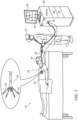
- Fig. 1 is a schematic, pictorial illustration of a system 21 for electrophysiological (EP) mapping, in accordance with an exemplary embodiment of the present invention.
- Fig. 1 depicts a physician 27 using an EP mapping catheter 29 to perform an EP mapping of a cardiac chamber (e.g., a left atrium (LA) and/or a right atrium (RA) and/or a left ventricle (LV), and/or a right ventricle (RV)) of a heart 23 of a patient 25.
- a cardiac chamber e.g., a left atrium (LA) and/or a right atrium (RA) and/or a left ventricle (LV), and/or a right ventricle (RV)
- Catheter 29 comprises, at its distal end, an electrode array 50 comprising one or more arms 20, with mapping-electrodes 22 disposed along each of the arms.
- electrodes 22 acquire and/or inject signals from and/or to the tissue of heart 23.
- electrodes 22 acquire IEGMs, such as atrial electrograms.
- mapping-electrodes 22 inside heart 23 are tracked as well, so that a processor 28 may link each acquired IEGM with the location at which the signal was acquired.
- System 20 externally senses electrical position signals and EP data, such as electrocardiograms (ECG), using a plurality of external electrodes 24 coupled to the body surface of patient 25; for simplicity, three external electrodes 24 may be coupled to the patient's chest, and another three external electrodes may be coupled to the patient's back. For ease of illustration, only one external electrode is shown in Fig. 1 .
- ACL Advanced Current Location
- processor 28 measures the electrical impedance between each of at least some of mapping-electrodes 22 and each of external electrodes 24 and finds location coordinates of the mapping-electrodes using these impedances.
- system 21 may apply other methods of position sensing that are known in the art, such as magnetic position sensing, in finding these location coordinates.
- mapping-electrodes 22 are conveyed over a wire link (not shown) that runs through catheter 29 to a data acquisition module 33 via an electrical interface 35.
- processor 28 of system 21 uses the sensed positions to establish spatiotemporal correlations between the electrograms to generate an EP map, such as an LAT map.
- the processor stores the EP map in a memory 31.
- processor 28 may present electrogram traces 40 on a display 26 of system 20.
- Fig. 1 The example illustration shown in Fig. 1 is chosen purely for the sake of conceptual clarity. Other types of multi-electrode sensing geometries, such as of the Lasso ® catheter (produced by Biosense Webster), may also be employed. Additionally, contact sensors may be fitted at the distal end of catheter 29 to transmit data indicative of the physical quality of electrode contact with tissue. In an embodiment, measurements of some electrodes 22 may be discarded because their physical contact quality is poor, and the measurements of other electrodes may be regarded as valid because their contact quality is high.
- Processor 28 typically comprises a general-purpose computer, which is programmed in software to carry out the functions described herein.
- the software may be downloaded to the computer in electronic form, over a network, for example, or it may, alternatively or additionally, be provided and/or stored on non-transitory tangible media, such as magnetic, optical, or electronic memory.
- processor 28 runs a dedicated algorithm that enables processor 28 to perform the steps described in Fig. 5 .
- Fig. 2 is a schematic, pictorial illustration of heart 23 with a His bundle 222, which is mapped by system 21 of Fig. 1 , in accordance with an exemplary embodiment of the present invention.
- EP mapping catheter 29 is positioned inside the left atrium (LA).
- Mapping-electrodes 22 in array 50 are pressed against tissue in the vicinity of His bundle 222 to acquire EP signals (e.g., IEGMs) that might be propagating in His bundle 222.
- IEGMs e.g., IEGMs
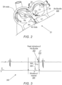
- Fig. 3 is a graph of an intracardiac electrogram (IEGM) signal 300 acquired by system 21 of Fig. 1 , with a peak 303 indicative of His bundle 222, in accordance with an embodiment of the present invention.
- Peak 303 is already received annotated, indicating the time of occurrence of peak 303 relative to a predefined reference annotation 306.
- the respective time difference 308 is a LAT value of peak 303 to be used in a His-indicative LAT map, if peak 303 is found to be a His peak.
- Processor 28 uses the aforementioned automatic His bundle detection algorithm to detect the His bundle signal within a temporal window of interest (WOI) 304, which is defined by the physician on the basis of atrial mapping. Additionally, or alternatively, processor 28 may be programmed to set the bounds of WOI 304 automatically.
- WOI temporal window of interest
- peak 303 which identifies His bundle 222, appears late in WOI 304.
- the disclosed method to detect the His bundle includes finding a subset of data points, such as peak 303 and a respective tissue location of the signal, in order to identify only those data points that occur this late in the WOI and to separate them from points earlier in the WOI.
- processor 28 can distinguish the peak by passing signal 300 through a high pass filter (e.g., above 200 Hz) to leave only narrow sharp peaks, which could be indicative of the His bundle peak.
- a high pass filter e.g., above 200 Hz
- a peak detection algorithm used by processor 28 is applied to each filtered signal to detect peaks above a certain limit (e.g., above 30 microvolts). Peak detection may be carried out, for example, using smoothing and then fitting a known function (e.g., a polynomial) to the waveform. Alternatively, processor 28 can match a known peak shape to the waveform. Further alternatively, peaks and troughs can be detected by finding zero-crossings (i.e., local maxima) in the differences (slope sign change) between a point and its neighbors.
- Reference annotation 306 may be identified, for example, on the basis of a peak in a body-surface electrocardiogram or an IEGM signal captured at a reference location within heart 23.
- Processor 28 calculates a time difference ⁇ T 310 between peak 303 and end boundary of WOI 304. If ⁇ T ⁇ threshold, processor 28 tags peak 303 on an EP map, such as the EP map shown in and described with respect to Fig. 4 below, to indicate that the identification of the His bundle is based on the location of EP peak signal 303. For example, if the time of occurrence of peak 303 is late enough (e.g., within 20-50 ms of the end of the WOI and the peak width 303 is small enough (e.g., less than 20 ms), processor 28 assumes that the data point represented by signal 303 originates from the His bundle (up to passing the aforementioned cross correlation test). A tag is then added by the processor to the EP map, (such as the map shown in Fig. 4 below) to indicate that the identification of the His bundle is based on the location of EP peak signal 303.
- an EP map such as the EP map shown in and described with respect to Fig. 4 below
- Fig. 4 is a schematic, pictorial illustration of an EP map 400 of heart 23 generated by system 21 ( Fig. 1 ) and comprising a region 402 containing the His bundle 222, in accordance with an exemplary embodiment of the present invention.
- region 402 is characterized by long LAT values and is surrounded, at least in part, by cardiac tissue areas with short LAT values.
- Processor 28 marks region 402 in EP map 400 with an indication 408 (e.g., a letter "H"). Alternatively, or additionally, the processor colors the region with a particular color.
- Fig. 5 is a flow chart that schematically illustrates a method for automatic detection and tagging of the His bundle 222, in accordance with an exemplary embodiment of the present invention.
- the algorithm carries out a process that begins at a LAT data points receiving step 502, in which processor 28 receives time annotated data points located in and around the candidate late activation region 402 in LAT map 400 ( Fig. 4 ).
- processor 28 segments the received data points based on the respective annotation times using a clustering algorithm (e.g., k-means) to find a subset of the data points that may be indicative of the His bundle.
- a clustering algorithm e.g., k-means
- processor 28 then calculates time difference, ⁇ T, between candidate His peaks and the end of WOI 304.
- processor 28 compares ⁇ T to a threshold value. If ⁇ T ⁇ threshold, (i.e., a NO answer) processor 28 drops each of such irrelevant data point, at a data-points dropping step 510.
- processor 28 passes each IEGM signal of the data points through a high-pass filter (e.g., above 200 Hz) to leave only narrow sharp peaks, which could be indicative of the His bundle peak.
- a high-pass filter e.g., above 200 Hz
- processor 28 applies a peak detector algorithm to each filtered signal to detect peaks above a certain limit (e.g., above 30 microvolts).
- processor 29 cross correlates all remining candidate His peaks to make sure that they represent the same electrical activity.
- the processor maintains, at a step 518, only peaks with large enough cross correlation confident, C, as described above.
- processor 28 tags the found His peaks on the EP map, to indicate that the His bundle is based on the location of EP peak signal 303.
- processor 28 colors the His region on the EP map as shown in Fig. 4 , at a His region coloring step 522.
Landscapes
- Health & Medical Sciences (AREA)
- Life Sciences & Earth Sciences (AREA)
- Engineering & Computer Science (AREA)
- Physics & Mathematics (AREA)
- General Health & Medical Sciences (AREA)
- Biophysics (AREA)
- Pathology (AREA)
- Biomedical Technology (AREA)
- Heart & Thoracic Surgery (AREA)
- Medical Informatics (AREA)
- Molecular Biology (AREA)
- Surgery (AREA)
- Animal Behavior & Ethology (AREA)
- Public Health (AREA)
- Veterinary Medicine (AREA)
- Cardiology (AREA)
- Physiology (AREA)
- Artificial Intelligence (AREA)
- Computer Vision & Pattern Recognition (AREA)
- Psychiatry (AREA)
- Signal Processing (AREA)
- Human Computer Interaction (AREA)
- Fuzzy Systems (AREA)
- Evolutionary Computation (AREA)
- Radiology & Medical Imaging (AREA)
- Mathematical Physics (AREA)
- Nuclear Medicine, Radiotherapy & Molecular Imaging (AREA)
- Measurement And Recording Of Electrical Phenomena And Electrical Characteristics Of The Living Body (AREA)
- Investigating Or Analyzing Materials By The Use Of Electric Means (AREA)
- Investigating Or Analysing Biological Materials (AREA)
- Measuring Pulse, Heart Rate, Blood Pressure Or Blood Flow (AREA)
Abstract
Description
- The present invention relates generally to electrophysiological (EP) mapping, and particularly to detection of the His bundle by EP mapping and to visualization of the detected His bundle on an EP map.
- Measuring cardiac electrical activity occurring in the His bundle was previously proposed in the patent literature. For example,
U.S. Patent No. 10,285,647 - As another example, International Patent Application Publication
WO 2021/078,848 describes an implantable medical device for stimulating a heart, the device comprising a housing, a processor, a memory unit, a stimulation unit configured to stimulate the His bundle of the heart, and a detection unit configured to detect an electrical signal at the His bundle of the same heart. - An embodiment of the present invention that is described hereinafter provides a method including receiving intracardiac electrogram (IEGM) signals measured at a plurality of locations in a region of a heart that contains a His bundle of the heart. The IEGM signals are processed to find respective local activation time (LAT) values at the plurality of the locations. A cluster of the locations is identified at which peaks in the IEGM signals, associated with the LAT values, occur later than a defined time. For the locations, respective time differences are calculated between times of occurrence of the identified peaks and a reference time. The time differences are compared to a threshold value and retained are the locations for which the time differences are below the threshold value. The IEGM signals measured at the retained locations are filtered to identify respective high-frequency peaks in the IEGM signals. The identified high-frequency peaks are cross corelated to identify a subset of the locations whose high-frequency peaks meet a predefined cross-correlation level. The high-frequency peaks are tagged as His peaks, and indicated on a cardiac map.
- In some embodiments, indicating the tagged His peaks includes coloring a His region on the map.
- In some embodiments, identifying the cluster includes applying a clustering algorithm.
- In an embodiment, the reference time is an end time of a window of interest (WOI) provided by a user.
- In another embodiment, filtering the signals includes passing each of the IEGM signals through a high pass filter.
- In some embodiments, the IEGMs are acquired using a mapping catheter positioned in a cardiac chamber.
- The present invention will be more fully understood from the following detailed description of the embodiments thereof, taken together with the drawings in which:
-
Fig. 1 is a schematic, pictorial illustration of a system for electrophysiological (EP) mapping, in accordance with an exemplary embodiment of the present invention; -
Fig. 2 is a schematic, pictorial illustration of a heart with a His bundle that is EP mapped by the system ofFig. 1 , in accordance with an exemplary embodiment of the present invention; -
Fig. 3 is a graph of an intracardiac electrogram (IEGM) signal acquired by the system ofFig. 1 , the IEGM comprising a peak indicative of the His bundle, in accordance with an exemplary embodiment of the present invention; -
Fig. 4 is a schematic, pictorial illustration of an EP map of the heart generated by the system ofFig. 1 , the EP map comprising a representation of the His bundle region, in accordance with an exemplary embodiment of the present invention; and -
Fig. 5 is a flow chart that schematically illustrates a method for automatic detection and tagging of the His bundle, in accordance with an exemplary embodiment of the present invention. - Some electrophysiological (EP) disorders, such as cardiac arrhythmia, may be manifested in episodes of irregular EP signals, such as irregular intracardiac electrograms (IEGMs). A multi-electrode catheter may be used to acquire IEGMs to detect a cardiac tissue location causing the irregular IEGMs. After mapping, a physician may ablate detected arrhythmogenic tissue. Often, to generate an accurate EP map of cardiac tissue, a physician may be required to pace the heart from a certain tissue location inside the heart, such as from a vicinity of the His bundle.
- Catheter-based EP mapping techniques can produce various types of EP maps of a cardiac chamber, such as the left atrium of a heart. For example, cardiac EP maps, such as a local activation time (LAT) map, a bipolar potential map, or a unipolar potential map, are produced by acquiring IEGMs from locations on a heart chamber surface. EP values, such as LATs (or potentials), are then derived from the IEGMs for the locations. Such locations and respective EP values, called hereafter "data points," are then overlayed, typically as a color, onto a 3D map of the chamber.
- The His bundle is part of the Purkinje fibers in the heart, located between the heart chambers. The His bundle is a good place from which to pace, though this area should be avoided for ablation. Therefore, it is important to identify the His bundle on the EP map, e.g., by using a tag.
- However, the His bundle is difficult to identify from IEGMs captured in the atrium, as the identifying peak in the electrical signal is very small because the His bundle, which is primarily located in the ventricle, is itself also very small. Therefore, in order to detect a peak that identifies the His bundle, a catheter with many small electrodes is needed to capture accurate signals. Small electrodes for accuracy of the signals, and many electrodes to make sure that the catheter has a good chance of having some of its electrodes in the region of the His bundle. It is still very difficult for a physician to detect the His bundle from the IEGMs, due to the very small peak and the many IEGM signals to examine per catheter position.
- Embodiments of the present invention that are described hereinafter provide an automatic His bundledetection algorithm that is based on IEGMs collected by a multi-electrode catheter (e.g., a multi-arm catheter or a basket catheter), a created LAT map, and a window of interest (WOI) defined by the physician according to the atrial mapping of the atrium.
- The disclosed algorithm relies on the fact that the peak due to the His bundle generally appears very late in the WOI, and is seen on a LAT map as a late activation color-coded region, as shown below. The His bundle is also generally surrounded by a tissue area that produces relatively early activations. It should be noted that such a region of late activation on the LAT map does not always mean that the region is the His bundle. Instead, it indicates that the region is a candidate for being considered as the His bundle, subject to further tests described below.
- The disclosed method to detect the His bundle therefore includes the following algorithm steps:
- 1. Data points from the LAT map located in and around the candidate late activation region are segmented, based on annotation time. This segmentation may be performed, for example, using a clustering algorithm (e.g., k-means) to find a subset of data points possibly indicative of the His bundle. The subset is chosen to include only points very late in the WOI and to separate them from points earlier in the WOI.
- 2. Quantitively, a candidate peak needs further to have a time of occurrence that is late enough in the WOI, with a time difference relative to the WOI end, ΔT=(WOI_end_timing-peak_timing), satisfying a condition, ΔT <threshold, such as ΔT<30 mSec.
Note, however, such late activation within the WOI is still not necessarily indicative of His tissue. - 3. Each signal among the data points in the selected cluster is passed through a high-pass filter (e.g., a filter with a passband above 200 Hz) to leave only narrow sharp peaks, which could be indicative of an His bundle peak.
- 4. A peak detector algorithm is applied to each filtered signal to detect peaks above a certain limit (e.g., above 30 microvolts), to eliminate irrelevant sharp peaks, such as arising from far-field noise. Note, another method may be used to differentiate actual signal from noise, such one the uses the waveform derivative.
- 5. A processor calculates a mean time and standard deviation (SD) of the peaks remining after step 4.
- 6. The processor eliminates sharp peaks that are outliers, e.g., eliminates all peaks deviating from the mean by more than 3σ.
- 7. The processor then calculates a normalized cross correlation between all remining peaks to make sure that they represent the same activity. If the correlation coefficient for a given signal is above a given value C, such as C=0.75, the processor tags the signal as His Signals.
- 8. Finally the processor codes (e.g., colors) the EP map with distinctive pattern (e.g., color) for the region associated with the His tagged peaks (i.e., with LAT values of respective His peaks).
- In an exemplary embodiment, a system is provided that includes an interface and a processor. The interface is configured to receive intracardiac electrogram (IEGM) signals measured at a plurality of locations in a region of a heart that contains a His bundle of the heart. The processor processes the IEGM signals to find respective local activation time (LAT) values at the plurality of the locations. The processor then identifies a cluster of the locations at which peaks in the IEGM signals, associated with the LAT values, occur later than a defined time. For the locations in the identified cluster, the processor calculates respective time differences between times of occurrence of the identified peaks and a reference time. Next, the processor compares the time differences to a threshold value and retains the locations for which the time differences are below the threshold value. The processor filters the IEGM signals measured at the retained locations to identify respective high-frequency peaks in the IEGM signals. Next, the processor cross corelates the identified high-frequency peaks, and identifies a subset of the locations whose high-frequency peaks meet a predefined cross-correlation level. The processor tags the high-frequency peaks corresponding to the locations in the subset as His peaks, and, finally, indicates the tagged His peaks on a map of at least a portion of the heart.
- By providing automated His bundle detection and tagging during EP mapping, catheter-based diagnostic and/or therapeutic (e.g., ablative) procedures can be made safer and more effective.
-
Fig. 1 is a schematic, pictorial illustration of asystem 21 for electrophysiological (EP) mapping, in accordance with an exemplary embodiment of the present invention.Fig. 1 depicts aphysician 27 using anEP mapping catheter 29 to perform an EP mapping of a cardiac chamber (e.g., a left atrium (LA) and/or a right atrium (RA) and/or a left ventricle (LV), and/or a right ventricle (RV)) of aheart 23 of apatient 25. -
Catheter 29 comprises, at its distal end, anelectrode array 50 comprising one ormore arms 20, with mapping-electrodes 22 disposed along each of the arms. During the EP mapping procedure,electrodes 22 acquire and/or inject signals from and/or to the tissue ofheart 23. In particular,electrodes 22 acquire IEGMs, such as atrial electrograms. - The respective locations of mapping-
electrodes 22 inside heart 23 (i.e., where the IEGMs are measured) are tracked as well, so that aprocessor 28 may link each acquired IEGM with the location at which the signal was acquired.System 20 externally senses electrical position signals and EP data, such as electrocardiograms (ECG), using a plurality ofexternal electrodes 24 coupled to the body surface ofpatient 25; for simplicity, threeexternal electrodes 24 may be coupled to the patient's chest, and another three external electrodes may be coupled to the patient's back. For ease of illustration, only one external electrode is shown inFig. 1 . - An example of a system capable of using the sensed electrical position signals to track the locations of mapping-
electrodes 22 insideheart 23 of the patient is the CARTO®3 system (produced by Biosense Webster Inc., Irvine, California). The CARTO®3 system uses a tracking method named Advanced Current Location (ACL), which is described in detail inU.S. Patent No. 8,456,182 , whose disclosure is incorporated herein by reference. According to this method,processor 28 measures the electrical impedance between each of at least some of mapping-electrodes 22 and each ofexternal electrodes 24 and finds location coordinates of the mapping-electrodes using these impedances. Alternatively or additionally,system 21 may apply other methods of position sensing that are known in the art, such as magnetic position sensing, in finding these location coordinates. - The IEGMs captured by mapping-
electrodes 22 are conveyed over a wire link (not shown) that runs throughcatheter 29 to adata acquisition module 33 via anelectrical interface 35. Using the sensed positions to establish spatiotemporal correlations between the electrograms,processor 28 ofsystem 21 generates an EP map, such as an LAT map. The processor stores the EP map in amemory 31. In parallel,processor 28 may present electrogram traces 40 on adisplay 26 ofsystem 20. - The example illustration shown in
Fig. 1 is chosen purely for the sake of conceptual clarity. Other types of multi-electrode sensing geometries, such as of the Lasso® catheter (produced by Biosense Webster), may also be employed. Additionally, contact sensors may be fitted at the distal end ofcatheter 29 to transmit data indicative of the physical quality of electrode contact with tissue. In an embodiment, measurements of someelectrodes 22 may be discarded because their physical contact quality is poor, and the measurements of other electrodes may be regarded as valid because their contact quality is high. - Although exemplary embodiments of the present invention are described above, for the sake of concreteness and clarity, with specific reference to the elements of
system 21, the principles of the present invention may similarly be applied in other EP mapping systems with suitable sensing capabilities. All such alternative embodiments are considered to be within the scope of the present invention. -
Processor 28 typically comprises a general-purpose computer, which is programmed in software to carry out the functions described herein. The software may be downloaded to the computer in electronic form, over a network, for example, or it may, alternatively or additionally, be provided and/or stored on non-transitory tangible media, such as magnetic, optical, or electronic memory. In particular,processor 28 runs a dedicated algorithm that enablesprocessor 28 to perform the steps described inFig. 5 . -
Fig. 2 is a schematic, pictorial illustration ofheart 23 with a Hisbundle 222, which is mapped bysystem 21 ofFig. 1 , in accordance with an exemplary embodiment of the present invention. To perform such mapping,EP mapping catheter 29 is positioned inside the left atrium (LA). Mapping-electrodes 22 inarray 50 are pressed against tissue in the vicinity of Hisbundle 222 to acquire EP signals (e.g., IEGMs) that might be propagating in Hisbundle 222. An example of such an IEGM signal is shown inFig. 3 . -
Fig. 3 is a graph of an intracardiac electrogram (IEGM) signal 300 acquired bysystem 21 ofFig. 1 , with apeak 303 indicative of Hisbundle 222, in accordance with an embodiment of the present invention.Peak 303 is already received annotated, indicating the time of occurrence ofpeak 303 relative to a predefined reference annotation 306. In the shown embodiment, therespective time difference 308 is a LAT value ofpeak 303 to be used in a His-indicative LAT map, ifpeak 303 is found to be a His peak. -
Processor 28 uses the aforementioned automatic His bundle detection algorithm to detect the His bundle signal within a temporal window of interest (WOI) 304, which is defined by the physician on the basis of atrial mapping. Additionally, or alternatively,processor 28 may be programmed to set the bounds ofWOI 304 automatically. - As seen, peak 303, which identifies His
bundle 222, appears late inWOI 304. The disclosed method to detect the His bundle includes finding a subset of data points, such aspeak 303 and a respective tissue location of the signal, in order to identify only those data points that occur this late in the WOI and to separate them from points earlier in the WOI. - As
peak 303 is narrow,processor 28 can distinguish the peak by passingsignal 300 through a high pass filter (e.g., above 200 Hz) to leave only narrow sharp peaks, which could be indicative of the His bundle peak. - A peak detection algorithm used by
processor 28 is applied to each filtered signal to detect peaks above a certain limit (e.g., above 30 microvolts). Peak detection may be carried out, for example, using smoothing and then fitting a known function (e.g., a polynomial) to the waveform. Alternatively,processor 28 can match a known peak shape to the waveform. Further alternatively, peaks and troughs can be detected by finding zero-crossings (i.e., local maxima) in the differences (slope sign change) between a point and its neighbors. - Any suitable peak detection algorithm that is known in the art may be used for this purpose, including amplitude-based and gradient-based algorithms. Reference annotation 306 may be identified, for example, on the basis of a peak in a body-surface electrocardiogram or an IEGM signal captured at a reference location within
heart 23. -
Processor 28 calculates a time difference ΔT 310 betweenpeak 303 and end boundary ofWOI 304. If ΔT < threshold,processor 28 tags peak 303 on an EP map, such as the EP map shown in and described with respect toFig. 4 below, to indicate that the identification of the His bundle is based on the location ofEP peak signal 303. For example, if the time of occurrence ofpeak 303 is late enough (e.g., within 20-50 ms of the end of the WOI and thepeak width 303 is small enough (e.g., less than 20 ms),processor 28 assumes that the data point represented bysignal 303 originates from the His bundle (up to passing the aforementioned cross correlation test). A tag is then added by the processor to the EP map, (such as the map shown inFig. 4 below) to indicate that the identification of the His bundle is based on the location ofEP peak signal 303. -
Fig. 4 is a schematic, pictorial illustration of anEP map 400 ofheart 23 generated by system 21 (Fig. 1 ) and comprising aregion 402 containing the Hisbundle 222, in accordance with an exemplary embodiment of the present invention. As seen usingLAT scale 404,region 402 is characterized by long LAT values and is surrounded, at least in part, by cardiac tissue areas with short LAT values.Processor 28marks region 402 inEP map 400 with an indication 408 (e.g., a letter "H"). Alternatively, or additionally, the processor colors the region with a particular color. -
Fig. 5 is a flow chart that schematically illustrates a method for automatic detection and tagging of the Hisbundle 222, in accordance with an exemplary embodiment of the present invention. The algorithm, according to the presented exemplary embodiment, carries out a process that begins at a LAT datapoints receiving step 502, in whichprocessor 28 receives time annotated data points located in and around the candidatelate activation region 402 in LAT map 400 (Fig. 4 ). - At a
segmentation step 504,processor 28 segments the received data points based on the respective annotation times using a clustering algorithm (e.g., k-means) to find a subset of the data points that may be indicative of the His bundle. - At a
timing calculation step 506,processor 28 then calculates time difference, ΔT, between candidate His peaks and the end ofWOI 304. In acomparison step 508,processor 28 compares ΔT to a threshold value. If ΔT ≥ threshold, (i.e., a NO answer)processor 28 drops each of such irrelevant data point, at a data-points dropping step 510. - The rest of data-points go through a
filtration step 512, in whichprocessor 28 passes each IEGM signal of the data points through a high-pass filter (e.g., above 200 Hz) to leave only narrow sharp peaks, which could be indicative of the His bundle peak. - Next, at a His
peak detection step 514,processor 28 applies a peak detector algorithm to each filtered signal to detect peaks above a certain limit (e.g., above 30 microvolts). - At a
cross-correlation step 516,processor 29 cross correlates all remining candidate His peaks to make sure that they represent the same electrical activity. The processor maintains, at astep 518, only peaks with large enough cross correlation confident, C, as described above. - Next, at a tagging
step 520,processor 28 tags the found His peaks on the EP map, to indicate that the His bundle is based on the location ofEP peak signal 303. - Finally,
processor 28 colors the His region on the EP map as shown inFig. 4 , at a Hisregion coloring step 522. - It will be appreciated that the embodiments described above are cited by way of example, and that the present invention is not limited to what has been particularly shown and described hereinabove. Rather, the scope of the present invention includes both combinations and subcombinations of the various features described hereinabove, as well as variations and modifications thereof which would occur to persons skilled in the art upon reading the foregoing description and which are not disclosed in the prior art. Documents incorporated by reference in the present patent application are to be considered an integral part of the application except that to the extent any terms are defined in these incorporated documents in a manner that conflicts with the definitions made explicitly or implicitly in the present specification, only the definitions in the present specification should be considered.
Claims (12)
- A method, comprising:receiving intracardiac electrogram (IEGM) signals measured at a plurality of locations in a region of a heart that contains a His bundle of the heart;processing the IEGM signals to find respective local activation time (LAT) values at the plurality of the locations;identifying a cluster of the locations at which peaks in the IEGM signals, associated with the LAT values, occur later than a defined time;for the locations in the identified cluster, calculating respective time differences between times of occurrence of the identified peaks and a reference time;comparing the time differences to a threshold value and retaining the locations for which the time differences are below the threshold value;filtering the IEGM signals measured at the retained locations to identify respective high-frequency peaks in the IEGM signals;cross corelating the identified high-frequency peaks, and identifying a subset of the locations whose high-frequency peaks meet a predefined cross-correlation level;tagging the high-frequency peaks corresponding to the locations in the subset as His peaks; andindicating the tagged His peaks on a map of at least a portion of the heart.
- The method according to claim 1, wherein indicating the tagged His peaks comprises coloring a His region on the map.
- The method according to claim 1, wherein identifying the cluster comprises applying a clustering algorithm.
- The method according to claim 1, wherein the reference time is an end time of a window of interest (WOI) provided by a user.
- The method according to claim 1, wherein filtering the signals comprises passing each of the IEGM signals through a high pass filter.
- The method according to claim 1, wherein the IEGMs are acquired using a mapping catheter positioned in a cardiac chamber.
- A system, comprising:an interface configured to receive intracardiac electrogram (IEGM) signals measured at a plurality of locations in a region of a heart that contains a His bundle of the heart; anda processor, which is configured to:process the IEGM signals to find respective local activation time (LAT) values at the plurality of the locations;identify a cluster of the locations at which peaks in the IEGM signals, associated with the LAT values, occur later than a defined time;for the locations in the identified cluster, calculate respective time differences between times of occurrence of the identified peaks and a reference time;compare the time differences to a threshold value and retain the locations for which the time differences are below the threshold value;filter the IEGM signals measured at the retained locations to identify respective high-frequency peaks in the IEGM signals;cross corelate the identified high-frequency peaks, and identify a subset of the locations whose high-frequency peaks meet a predefined cross-correlation level;tag the high-frequency peaks corresponding to the locations in the subset as His peaks; andindicate the tagged His peaks on a map of at least a portion of the heart.
- The system according to claim 7, wherein the processor is configured to indicate the tagged His peaks by coloring a His region on the map.
- The system according to claim 7, wherein the processor is configured to identify the cluster by applying a clustering algorithm.
- The system according to claim 7, wherein the reference time is an end time of a window of interest (WOI) provided by a user.
- The system according to claim 7, wherein the processor is configured to filter the signals by passing each of the IEGM signals through a high pass filter.
- The system according to claim 7, wherein the IEGMs are acquired using a mapping catheter positioned in a cardiac chamber.
Applications Claiming Priority (1)
| Application Number | Priority Date | Filing Date | Title |
|---|---|---|---|
| US17/481,600 US12458269B2 (en) | 2021-09-22 | 2021-09-22 | Automatic detection of the his bundle during electrophysiological mapping |
Publications (3)
| Publication Number | Publication Date |
|---|---|
| EP4159127A1 true EP4159127A1 (en) | 2023-04-05 |
| EP4159127C0 EP4159127C0 (en) | 2024-03-06 |
| EP4159127B1 EP4159127B1 (en) | 2024-03-06 |
Family
ID=83400773
Family Applications (1)
| Application Number | Title | Priority Date | Filing Date |
|---|---|---|---|
| EP22196751.6A Active EP4159127B1 (en) | 2021-09-22 | 2022-09-21 | Automatic detection of the his bundle during electrophysiological mapping |
Country Status (5)
| Country | Link |
|---|---|
| US (1) | US12458269B2 (en) |
| EP (1) | EP4159127B1 (en) |
| JP (1) | JP2023046310A (en) |
| CN (1) | CN115886835A (en) |
| IL (1) | IL296307B2 (en) |
Families Citing this family (2)
| Publication number | Priority date | Publication date | Assignee | Title |
|---|---|---|---|---|
| EP4599768A1 (en) * | 2024-02-07 | 2025-08-13 | Biosense Webster (Israel) Ltd. | Local ecg annotation visualization |
| US20250387066A1 (en) * | 2024-06-19 | 2025-12-25 | Biosense Webster (Israel) Ltd. | Systems and methods of mapping electrophysiological landmarks within a heart |
Citations (5)
| Publication number | Priority date | Publication date | Assignee | Title |
|---|---|---|---|---|
| US8456182B2 (en) | 2008-09-30 | 2013-06-04 | Biosense Webster, Inc. | Current localization tracker |
| US10285647B2 (en) | 2014-05-05 | 2019-05-14 | Pacesetter Inc. | Method and system to automatically assign map points to anatomical segments and determine mechanical activation time |
| US20200353266A1 (en) * | 2019-05-07 | 2020-11-12 | Pacesetter, Inc. | Time domain-based methods for his bundle capture classification |
| US20210016096A1 (en) * | 2019-07-18 | 2021-01-21 | Pacesetter, Inc. | Method and device for verifying atrial activity oversensing consistency on his sensing channel |
| WO2021078848A1 (en) | 2019-10-24 | 2021-04-29 | Biotronik Se & Co. Kg | Implantable medical device for stimulating the his bundle of a human or animal heart employing an adapted impedance measurement |
Family Cites Families (2)
| Publication number | Priority date | Publication date | Assignee | Title |
|---|---|---|---|---|
| US7596412B1 (en) * | 2004-08-26 | 2009-09-29 | Pacesetter, Inc. | Opto-electrical coherence detection of hemodynamically compromising arrhythmia |
| US11272887B2 (en) * | 2017-04-18 | 2022-03-15 | Boston Scientific Scimed Inc. | Electroanatomical mapping tools facilitated by activation waveforms |
-
2021
- 2021-09-22 US US17/481,600 patent/US12458269B2/en active Active
-
2022
- 2022-09-07 IL IL296307A patent/IL296307B2/en unknown
- 2022-09-21 EP EP22196751.6A patent/EP4159127B1/en active Active
- 2022-09-21 JP JP2022149967A patent/JP2023046310A/en active Pending
- 2022-09-22 CN CN202211169904.8A patent/CN115886835A/en active Pending
Patent Citations (5)
| Publication number | Priority date | Publication date | Assignee | Title |
|---|---|---|---|---|
| US8456182B2 (en) | 2008-09-30 | 2013-06-04 | Biosense Webster, Inc. | Current localization tracker |
| US10285647B2 (en) | 2014-05-05 | 2019-05-14 | Pacesetter Inc. | Method and system to automatically assign map points to anatomical segments and determine mechanical activation time |
| US20200353266A1 (en) * | 2019-05-07 | 2020-11-12 | Pacesetter, Inc. | Time domain-based methods for his bundle capture classification |
| US20210016096A1 (en) * | 2019-07-18 | 2021-01-21 | Pacesetter, Inc. | Method and device for verifying atrial activity oversensing consistency on his sensing channel |
| WO2021078848A1 (en) | 2019-10-24 | 2021-04-29 | Biotronik Se & Co. Kg | Implantable medical device for stimulating the his bundle of a human or animal heart employing an adapted impedance measurement |
Non-Patent Citations (1)
| Title |
|---|
| KUO C-T ET AL: "Electrophysiologic significance of discrete slow potentials in dual atrioventricular node physiology: Implications for selective radiofrequency ablation of slow pathway conduction", AMERICAN HEART JOURNAL, ELSEVIER, AMSTERDAM, NL, vol. 131, no. 3, 1 March 1996 (1996-03-01), pages 490 - 498, XP004530605, ISSN: 0002-8703, DOI: 10.1016/S0002-8703(96)90527-X * |
Also Published As
| Publication number | Publication date |
|---|---|
| IL296307B2 (en) | 2025-07-01 |
| CN115886835A (en) | 2023-04-04 |
| IL296307B1 (en) | 2025-03-01 |
| EP4159127C0 (en) | 2024-03-06 |
| EP4159127B1 (en) | 2024-03-06 |
| IL296307A (en) | 2023-04-01 |
| US20230087423A1 (en) | 2023-03-23 |
| US12458269B2 (en) | 2025-11-04 |
| JP2023046310A (en) | 2023-04-03 |
Similar Documents
| Publication | Publication Date | Title |
|---|---|---|
| JP7789485B2 (en) | Automatic Pattern Acquisition | |
| CN112401901B (en) | Electroanatomical map re-annotation | |
| CN104434299A (en) | Method for mapping ventricular/atrial premature beats during sinus rhythm | |
| US11832951B2 (en) | Handling ectopic beats in electro-anatomical mapping of the heart | |
| AU2015271946A1 (en) | Ventricular far field reduction | |
| EP4159127B1 (en) | Automatic detection of the his bundle during electrophysiological mapping | |
| US11006886B2 (en) | Visualization of different cardiac rhythms using different timing-pattern displays | |
| US20230172519A1 (en) | Annotation of late potentials comprising local abnormal ventricular activation (lava) signals | |
| EP3834727B1 (en) | Detection of ventricular activity using unipolar and bipolar signals | |
| US12336832B2 (en) | P-wave detection using intracardiac electrodes | |
| EP4570168A1 (en) | Gui to visually connect features identified in electroanatomical (ea) map to ecg signals | |
| EP4647011A1 (en) | Ventricular tachycardia (vt) target identification by selective pacing | |
| CN121170334A (en) | System and method for mapping electrophysiology feature points within a heart | |
| CN119997879A (en) | Detection of electrophysiological (EP) conduction gaps in ablation lines |
Legal Events
| Date | Code | Title | Description |
|---|---|---|---|
| PUAI | Public reference made under article 153(3) epc to a published international application that has entered the european phase |
Free format text: ORIGINAL CODE: 0009012 |
|
| STAA | Information on the status of an ep patent application or granted ep patent |
Free format text: STATUS: THE APPLICATION HAS BEEN PUBLISHED |
|
| STAA | Information on the status of an ep patent application or granted ep patent |
Free format text: STATUS: REQUEST FOR EXAMINATION WAS MADE |
|
| AK | Designated contracting states |
Kind code of ref document: A1 Designated state(s): AL AT BE BG CH CY CZ DE DK EE ES FI FR GB GR HR HU IE IS IT LI LT LU LV MC MK MT NL NO PL PT RO RS SE SI SK SM TR |
|
| 17P | Request for examination filed |
Effective date: 20230330 |
|
| RBV | Designated contracting states (corrected) |
Designated state(s): AL AT BE BG CH CY CZ DE DK EE ES FI FR GB GR HR HU IE IS IT LI LT LU LV MC MK MT NL NO PL PT RO RS SE SI SK SM TR |
|
| GRAP | Despatch of communication of intention to grant a patent |
Free format text: ORIGINAL CODE: EPIDOSNIGR1 |
|
| STAA | Information on the status of an ep patent application or granted ep patent |
Free format text: STATUS: GRANT OF PATENT IS INTENDED |
|
| INTG | Intention to grant announced |
Effective date: 20231023 |
|
| GRAS | Grant fee paid |
Free format text: ORIGINAL CODE: EPIDOSNIGR3 |
|
| GRAA | (expected) grant |
Free format text: ORIGINAL CODE: 0009210 |
|
| STAA | Information on the status of an ep patent application or granted ep patent |
Free format text: STATUS: THE PATENT HAS BEEN GRANTED |
|
| AK | Designated contracting states |
Kind code of ref document: B1 Designated state(s): AL AT BE BG CH CY CZ DE DK EE ES FI FR GB GR HR HU IE IS IT LI LT LU LV MC MK MT NL NO PL PT RO RS SE SI SK SM TR |
|
| REG | Reference to a national code |
Ref country code: CH Ref legal event code: EP |
|
| REG | Reference to a national code |
Ref country code: DE Ref legal event code: R096 Ref document number: 602022002253 Country of ref document: DE |
|
| REG | Reference to a national code |
Ref country code: IE Ref legal event code: FG4D |
|
| U01 | Request for unitary effect filed |
Effective date: 20240403 |
|
| U07 | Unitary effect registered |
Designated state(s): AT BE BG DE DK EE FI FR IT LT LU LV MT NL PT SE SI Effective date: 20240411 |
|
| PG25 | Lapsed in a contracting state [announced via postgrant information from national office to epo] |
Ref country code: GR Free format text: LAPSE BECAUSE OF FAILURE TO SUBMIT A TRANSLATION OF THE DESCRIPTION OR TO PAY THE FEE WITHIN THE PRESCRIBED TIME-LIMIT Effective date: 20240607 |
|
| PG25 | Lapsed in a contracting state [announced via postgrant information from national office to epo] |
Ref country code: HR Free format text: LAPSE BECAUSE OF FAILURE TO SUBMIT A TRANSLATION OF THE DESCRIPTION OR TO PAY THE FEE WITHIN THE PRESCRIBED TIME-LIMIT Effective date: 20240306 Ref country code: RS Free format text: LAPSE BECAUSE OF FAILURE TO SUBMIT A TRANSLATION OF THE DESCRIPTION OR TO PAY THE FEE WITHIN THE PRESCRIBED TIME-LIMIT Effective date: 20240606 |
|
| PG25 | Lapsed in a contracting state [announced via postgrant information from national office to epo] |
Ref country code: ES Free format text: LAPSE BECAUSE OF FAILURE TO SUBMIT A TRANSLATION OF THE DESCRIPTION OR TO PAY THE FEE WITHIN THE PRESCRIBED TIME-LIMIT Effective date: 20240306 |
|
| PG25 | Lapsed in a contracting state [announced via postgrant information from national office to epo] |
Ref country code: RS Free format text: LAPSE BECAUSE OF FAILURE TO SUBMIT A TRANSLATION OF THE DESCRIPTION OR TO PAY THE FEE WITHIN THE PRESCRIBED TIME-LIMIT Effective date: 20240606 Ref country code: NO Free format text: LAPSE BECAUSE OF FAILURE TO SUBMIT A TRANSLATION OF THE DESCRIPTION OR TO PAY THE FEE WITHIN THE PRESCRIBED TIME-LIMIT Effective date: 20240606 Ref country code: HR Free format text: LAPSE BECAUSE OF FAILURE TO SUBMIT A TRANSLATION OF THE DESCRIPTION OR TO PAY THE FEE WITHIN THE PRESCRIBED TIME-LIMIT Effective date: 20240306 Ref country code: GR Free format text: LAPSE BECAUSE OF FAILURE TO SUBMIT A TRANSLATION OF THE DESCRIPTION OR TO PAY THE FEE WITHIN THE PRESCRIBED TIME-LIMIT Effective date: 20240607 Ref country code: ES Free format text: LAPSE BECAUSE OF FAILURE TO SUBMIT A TRANSLATION OF THE DESCRIPTION OR TO PAY THE FEE WITHIN THE PRESCRIBED TIME-LIMIT Effective date: 20240306 |
|
| U20 | Renewal fee for the european patent with unitary effect paid |
Year of fee payment: 3 Effective date: 20240807 |
|
| PG25 | Lapsed in a contracting state [announced via postgrant information from national office to epo] |
Ref country code: IS Free format text: LAPSE BECAUSE OF FAILURE TO SUBMIT A TRANSLATION OF THE DESCRIPTION OR TO PAY THE FEE WITHIN THE PRESCRIBED TIME-LIMIT Effective date: 20240706 |
|
| PG25 | Lapsed in a contracting state [announced via postgrant information from national office to epo] |
Ref country code: SM Free format text: LAPSE BECAUSE OF FAILURE TO SUBMIT A TRANSLATION OF THE DESCRIPTION OR TO PAY THE FEE WITHIN THE PRESCRIBED TIME-LIMIT Effective date: 20240306 |
|
| PG25 | Lapsed in a contracting state [announced via postgrant information from national office to epo] |
Ref country code: CZ Free format text: LAPSE BECAUSE OF FAILURE TO SUBMIT A TRANSLATION OF THE DESCRIPTION OR TO PAY THE FEE WITHIN THE PRESCRIBED TIME-LIMIT Effective date: 20240306 |
|
| PG25 | Lapsed in a contracting state [announced via postgrant information from national office to epo] |
Ref country code: PL Free format text: LAPSE BECAUSE OF FAILURE TO SUBMIT A TRANSLATION OF THE DESCRIPTION OR TO PAY THE FEE WITHIN THE PRESCRIBED TIME-LIMIT Effective date: 20240306 |
|
| PG25 | Lapsed in a contracting state [announced via postgrant information from national office to epo] |
Ref country code: SK Free format text: LAPSE BECAUSE OF FAILURE TO SUBMIT A TRANSLATION OF THE DESCRIPTION OR TO PAY THE FEE WITHIN THE PRESCRIBED TIME-LIMIT Effective date: 20240306 |
|
| PG25 | Lapsed in a contracting state [announced via postgrant information from national office to epo] |
Ref country code: SM Free format text: LAPSE BECAUSE OF FAILURE TO SUBMIT A TRANSLATION OF THE DESCRIPTION OR TO PAY THE FEE WITHIN THE PRESCRIBED TIME-LIMIT Effective date: 20240306 Ref country code: SK Free format text: LAPSE BECAUSE OF FAILURE TO SUBMIT A TRANSLATION OF THE DESCRIPTION OR TO PAY THE FEE WITHIN THE PRESCRIBED TIME-LIMIT Effective date: 20240306 Ref country code: RO Free format text: LAPSE BECAUSE OF FAILURE TO SUBMIT A TRANSLATION OF THE DESCRIPTION OR TO PAY THE FEE WITHIN THE PRESCRIBED TIME-LIMIT Effective date: 20240306 Ref country code: PL Free format text: LAPSE BECAUSE OF FAILURE TO SUBMIT A TRANSLATION OF THE DESCRIPTION OR TO PAY THE FEE WITHIN THE PRESCRIBED TIME-LIMIT Effective date: 20240306 Ref country code: IS Free format text: LAPSE BECAUSE OF FAILURE TO SUBMIT A TRANSLATION OF THE DESCRIPTION OR TO PAY THE FEE WITHIN THE PRESCRIBED TIME-LIMIT Effective date: 20240706 Ref country code: CZ Free format text: LAPSE BECAUSE OF FAILURE TO SUBMIT A TRANSLATION OF THE DESCRIPTION OR TO PAY THE FEE WITHIN THE PRESCRIBED TIME-LIMIT Effective date: 20240306 |
|
| REG | Reference to a national code |
Ref country code: DE Ref legal event code: R097 Ref document number: 602022002253 Country of ref document: DE |
|
| PLBE | No opposition filed within time limit |
Free format text: ORIGINAL CODE: 0009261 |
|
| STAA | Information on the status of an ep patent application or granted ep patent |
Free format text: STATUS: NO OPPOSITION FILED WITHIN TIME LIMIT |
|
| 26N | No opposition filed |
Effective date: 20241209 |
|
| PG25 | Lapsed in a contracting state [announced via postgrant information from national office to epo] |
Ref country code: MC Free format text: LAPSE BECAUSE OF FAILURE TO SUBMIT A TRANSLATION OF THE DESCRIPTION OR TO PAY THE FEE WITHIN THE PRESCRIBED TIME-LIMIT Effective date: 20240306 |
|
| PG25 | Lapsed in a contracting state [announced via postgrant information from national office to epo] |
Ref country code: IE Free format text: LAPSE BECAUSE OF NON-PAYMENT OF DUE FEES Effective date: 20240921 |
|
| U20 | Renewal fee for the european patent with unitary effect paid |
Year of fee payment: 4 Effective date: 20250807 |
|
| PG25 | Lapsed in a contracting state [announced via postgrant information from national office to epo] |
Ref country code: CY Free format text: LAPSE BECAUSE OF FAILURE TO SUBMIT A TRANSLATION OF THE DESCRIPTION OR TO PAY THE FEE WITHIN THE PRESCRIBED TIME-LIMIT; INVALID AB INITIO Effective date: 20220921 |
|
| PG25 | Lapsed in a contracting state [announced via postgrant information from national office to epo] |
Ref country code: HU Free format text: LAPSE BECAUSE OF FAILURE TO SUBMIT A TRANSLATION OF THE DESCRIPTION OR TO PAY THE FEE WITHIN THE PRESCRIBED TIME-LIMIT; INVALID AB INITIO Effective date: 20220921 |
|
| REG | Reference to a national code |
Ref country code: CH Ref legal event code: H13 Free format text: ST27 STATUS EVENT CODE: U-0-0-H10-H13 (AS PROVIDED BY THE NATIONAL OFFICE) Effective date: 20260504 |