EP4158730B1 - Aerosol provision device - Google Patents
Aerosol provision device Download PDFInfo
- Publication number
- EP4158730B1 EP4158730B1 EP21731570.4A EP21731570A EP4158730B1 EP 4158730 B1 EP4158730 B1 EP 4158730B1 EP 21731570 A EP21731570 A EP 21731570A EP 4158730 B1 EP4158730 B1 EP 4158730B1
- Authority
- EP
- European Patent Office
- Prior art keywords
- metal housing
- antenna signal
- aerosol provision
- provision device
- transmission
- Prior art date
- Legal status (The legal status is an assumption and is not a legal conclusion. Google has not performed a legal analysis and makes no representation as to the accuracy of the status listed.)
- Active
Links
Images




Classifications
-
- A—HUMAN NECESSITIES
- A24—TOBACCO; CIGARS; CIGARETTES; SIMULATED SMOKING DEVICES; SMOKERS' REQUISITES
- A24F—SMOKERS' REQUISITES; MATCH BOXES; SIMULATED SMOKING DEVICES
- A24F40/00—Electrically operated smoking devices; Component parts thereof; Manufacture thereof; Maintenance or testing thereof; Charging means specially adapted therefor
- A24F40/10—Devices using liquid inhalable precursors
-
- A—HUMAN NECESSITIES
- A24—TOBACCO; CIGARS; CIGARETTES; SIMULATED SMOKING DEVICES; SMOKERS' REQUISITES
- A24F—SMOKERS' REQUISITES; MATCH BOXES; SIMULATED SMOKING DEVICES
- A24F40/00—Electrically operated smoking devices; Component parts thereof; Manufacture thereof; Maintenance or testing thereof; Charging means specially adapted therefor
- A24F40/40—Constructional details, e.g. connection of cartridges and battery parts
-
- A—HUMAN NECESSITIES
- A24—TOBACCO; CIGARS; CIGARETTES; SIMULATED SMOKING DEVICES; SMOKERS' REQUISITES
- A24F—SMOKERS' REQUISITES; MATCH BOXES; SIMULATED SMOKING DEVICES
- A24F40/00—Electrically operated smoking devices; Component parts thereof; Manufacture thereof; Maintenance or testing thereof; Charging means specially adapted therefor
- A24F40/40—Constructional details, e.g. connection of cartridges and battery parts
- A24F40/42—Cartridges or containers for inhalable precursors
-
- A—HUMAN NECESSITIES
- A24—TOBACCO; CIGARS; CIGARETTES; SIMULATED SMOKING DEVICES; SMOKERS' REQUISITES
- A24F—SMOKERS' REQUISITES; MATCH BOXES; SIMULATED SMOKING DEVICES
- A24F40/00—Electrically operated smoking devices; Component parts thereof; Manufacture thereof; Maintenance or testing thereof; Charging means specially adapted therefor
- A24F40/50—Control or monitoring
-
- A—HUMAN NECESSITIES
- A24—TOBACCO; CIGARS; CIGARETTES; SIMULATED SMOKING DEVICES; SMOKERS' REQUISITES
- A24F—SMOKERS' REQUISITES; MATCH BOXES; SIMULATED SMOKING DEVICES
- A24F40/00—Electrically operated smoking devices; Component parts thereof; Manufacture thereof; Maintenance or testing thereof; Charging means specially adapted therefor
- A24F40/65—Devices with integrated communication means, e.g. wireless communication means
-
- A—HUMAN NECESSITIES
- A24—TOBACCO; CIGARS; CIGARETTES; SIMULATED SMOKING DEVICES; SMOKERS' REQUISITES
- A24F—SMOKERS' REQUISITES; MATCH BOXES; SIMULATED SMOKING DEVICES
- A24F40/00—Electrically operated smoking devices; Component parts thereof; Manufacture thereof; Maintenance or testing thereof; Charging means specially adapted therefor
- A24F40/70—Manufacture
-
- H—ELECTRICITY
- H01—ELECTRIC ELEMENTS
- H01Q—ANTENNAS, i.e. RADIO AERIALS
- H01Q1/00—Details of, or arrangements associated with, antennas
- H01Q1/27—Adaptation for use in or on movable bodies
- H01Q1/273—Adaptation for carrying or wearing by persons or animals
-
- H—ELECTRICITY
- H01—ELECTRIC ELEMENTS
- H01Q—ANTENNAS, i.e. RADIO AERIALS
- H01Q1/00—Details of, or arrangements associated with, antennas
- H01Q1/36—Structural form of radiating elements, e.g. cone, spiral, umbrella; Particular materials used therewith
-
- H—ELECTRICITY
- H01—ELECTRIC ELEMENTS
- H01Q—ANTENNAS, i.e. RADIO AERIALS
- H01Q9/00—Electrically-short antennas having dimensions not more than twice the operating wavelength and consisting of conductive active radiating elements
- H01Q9/04—Resonant antennas
-
- H—ELECTRICITY
- H01—ELECTRIC ELEMENTS
- H01Q—ANTENNAS, i.e. RADIO AERIALS
- H01Q9/00—Electrically-short antennas having dimensions not more than twice the operating wavelength and consisting of conductive active radiating elements
- H01Q9/04—Resonant antennas
- H01Q9/0407—Substantially flat resonant element parallel to ground plane, e.g. patch antenna
- H01Q9/0421—Substantially flat resonant element parallel to ground plane, e.g. patch antenna with a shorting wall or a shorting pin at one end of the element
-
- H—ELECTRICITY
- H01—ELECTRIC ELEMENTS
- H01Q—ANTENNAS, i.e. RADIO AERIALS
- H01Q9/00—Electrically-short antennas having dimensions not more than twice the operating wavelength and consisting of conductive active radiating elements
- H01Q9/04—Resonant antennas
- H01Q9/0407—Substantially flat resonant element parallel to ground plane, e.g. patch antenna
- H01Q9/0471—Non-planar, stepped or wedge-shaped patch
Definitions
- the present specification relates to an aerosol provision device, in particular to a housing of an aerosol provision device.
- Smoking articles such as cigarettes, cigars and the like burn tobacco during use to create tobacco smoke. Attempts have been made to provide alternatives to these articles by creating products that release compounds without combusting.
- tobacco heating devices heat an aerosol provision substrate such as tobacco to form an aerosol by heating, but not burning, the substrate.
- An aerosol provision device such as aerosol provision devices known from TW M 592 171 U , US 2016/261020 A1 and CN 110 380 219 A , may be provided with a means for communication, for example for communication with a mobile communication device of a user of the device. There remains a need for further developments in this field.
- this specification describes a metal housing for an aerosol provision device (e.g. a housing for an electronic smoking article), the metal housing comprising: a printed circuit board mounted within the metal housing; a first contact spring providing an electrical connection between a first connection point on an inside of the metal housing and a ground connection of the printed circuit board; and a second contact spring providing an electrical connection between a second connection point on the inside surface of the metal housing and an antenna signal output for providing an antenna signal for transmission by the metal housing (such that the metal housing may be used as an antenna, such as a Bluetooth or WiFi antenna), wherein the metal housing comprises a radiating conductor element extending from a first surface element to a second surface element, wherein the first and second connection points are provided on the radiating conductor element and wherein a distance between the first and second surface elements is at least one quarter of a wavelength of the antenna signal transmission.
- the metal housing comprises a radiating conductor element extending from a first surface element to a second surface element, wherein the first and second connection points are provided on the radiating
- the radiating conductor element is an elliptical cylindrical radiating conductor element
- the first surface element is a first elliptical surface element
- the second surface element is a second elliptical surface element
- the metal housing may further comprise a signal feed source element and an antenna signal terminal, wherein the antenna signal terminal is connected to the second connection point and the signal feed source element is connected to the antenna signal terminal by the second contact spring.
- the metal housing may further comprise an impedance matching circuit, which impedance matching circuit may be adjustable.
- the impedance matching circuit may be provided on the printed circuit board.
- the metal housing may further comprise a control module for generating the antenna signal for transmission.
- the control module may be configured to cause the transmission of data (e.g. device usage data, battery levels etc.). These data may be collected and used (e.g. displayed or stored) by a user's mobile communication device (e.g. an application on the user's phone that is in communication with the aerosol provision device).
- the metal housing may fully enclose the printed circuit board.
- this specification describes a method comprising: inserting a printed circuit board into a metal housing for an aerosol provision device such that a first contact spring of the printed circuit board provides an electrical connection between a first connection point on an inside of the metal housing and a ground connection of the printed circuit board and a second contact spring of the printed circuit board provides an electrical connection between a second connection point on the inside surface of the metal housing and an antenna signal output for providing an antenna signal for transmission (e.g.
- the metal housing comprises a radiating conductor element extending from a first surface element to a second surface element, wherein the first and second connection points are provided on the radiating conductor element and wherein a distance between the first and second surface elements is at least one quarter of a wavelength of the antenna signal transmission.
- the antenna signal may be used for communications with a mobile communication device. Once inserted, the printed circuit board may be fully enclosed by the metal housing.
- the method may further comprise matching an impedance between the antenna signal generating circuit and the metal housing and may, for example, include adjusting the impedance matching.
- the method may further comprise generating the antenna signal for transmission.
- the antenna signal may be used for locating the aerosol provision device.
- this specification describes an aerosol provision device (e.g. a non-combustible aerosol provision device) comprising a metal housing including any of the features of the first aspect.
- this specification describes an electronic smoking article comprising an aerosol provision device of the third aspect.
- this specification describes a method comprising: receiving communications at a mobile communication device from an aerosol provision device of the third aspect or an electronic smoking article of the fourth aspect; and determining a location of said aerosol provision device or said electronic smoking article based on the received communications.
- the method may further comprise plotting the determined location on a display of said mobile communication device.
- this specification describes a kit of parts comprising an article (e.g. a removable article comprising an aerosol generating material) for use in a non-combustible aerosol generating system, wherein the non-combustible aerosol generating system comprises a metal housing including any of the features of the first aspect described above or a device or system including any of the features of the third or fourth aspects described above.
- an article e.g. a removable article comprising an aerosol generating material
- the aerosolisable material may comprise an active material, an aerosol forming material and optionally one or more functional materials.
- the active material may comprise nicotine (optionally contained in tobacco or a tobacco derivative) or one or more other non-olfactory physiologically active materials.
- a non-olfactory physiologically active material is a material which is included in the aerosolisable material in order to achieve a physiological response other than olfactory perception.
- the active substance as used herein may be a physiologically active material, which is a material intended to achieve or enhance a physiological response.
- the active substance may for example be selected from nutraceuticals, nootropics, psychoactives.
- the active substance may be naturally occurring or synthetically obtained.
- a user inhales from the mouthpiece 11.
- the cartridge of pod 12 may store a liquid solution (e.g. of glycerol, flavourings and nicotine).
- the control module 15 may include a communications means, such as a Bluetooth chip or WiFi chip.
- the communication means may be integrated into a microprocessor of the control module 15.
- An antenna (discussed in detail below) enables the communications means to communicate with a remote device (such as a mobile phone, a mobile communication device, a laptop, a computer or some other device), to enable information to be provided to a user.
- the antenna may be provided by a metal shell or housing (e.g. a shell, housing or sleeve of the aerosol provision device 10).
- the antenna may be planar inverted F (PIFA) antenna.
- the aerosol provision device 10 is provided by way of example only; many variants and alternatives are possible.
- the aerosol provision device 10 has an output that transmits a signal (such as a Bluetooth signal or a WiFi signal).
- the transmitted signal can be detected by the remote device 22 such that the aerosol provision device 10 can communicate with the remote device 22.
- the remote device 22 is able to transmit to the aerosol provision device 10 (as indicated by the dotted line in the system 20), but this is not essential to all embodiments.
- the signal transmitted from the aerosol provision device 10 to the remote device 22 may be used to transmit information such as how many e-cigarettes a user puffs or the amount of remaining liquid per day.
- the skilled person will be aware of many other examples of data that may be transmitted from the aerosol provision device 10 to the remote device 22 (or, indeed, data that may be transmitted from the remote device 22 to the aerosol provision device 10).
- FIG. 3 is a block diagram of a housing, indicated generally by the reference numeral 30, in accordance with an example embodiment.
- the housing 30 comprises an outer sleeve 31, such as an aluminium sleeve, which sleeve may provide the exterior of at least some of the aerosol provision device 10 described above. Note that the housing 30 may be used with alternative aerosol provisioning or generating devices and electronic smoking articles.
- a printed circuit board 32 and a battery 34 are mounted within the metal housing 30.
- the electronic components of the control module 15 may be provided on the printed circuit board 32.
- Other components may also be provided (such as the atomiser 13).
- the battery 34 is shown below the printed circuit board 32, this is just one example implementation.
- the printed circuit board and the battery may, for example, be provided side-by-side.
- a first contact spring 35a provides an electrical connection between a first connection point on an inside of the sleeve 31 and a ground connection of the printed circuit board.
- a second contact spring 35b provides an electrical connection between a second connection point on the inside surface of the sleeve 31 and an antenna signal output for providing an antenna signal for transmission by the metal housing (such that the metal housing 30 can be used as an antenna).
- FIG. 4 is a block diagram of a housing, indicated generally by the reference numeral 40, in accordance with an example that does not have all the claimed features.
- the housing 40 is an example implementation of the housing 30 described above.
- the housing 40 may be a sleeve.
- the housing 40 may be an elliptical cylindrical shape and may be resilient such that there is some flexibility in the shape of the housing.
- the housing 40 may be shaped dependent on a shape of the aerosol provision device 10 (and may, for example, have a circular, rectangular, elliptical, diamond or any other shape).
- the radiating conductor element 43 is an elliptical cylindrical radiating conductor element.
- the first and second surface elements 44 and 45 are elliptical surface elements.
- the housing 40 may be shaped dependent on a shape of the aerosol provision device 10 (and may, for example, have a circular, rectangular, elliptical, diamond or any other shape).
- the radiating conductor element 43 and the first and second surface elements 44 and 45 may be shaped based on the shape of the housing 40 and may therefore have a circular, rectangular, elliptical, diamond or any other shape.
- the signal feed source element 41 is connected to the antenna signal terminal 42 and the antenna signal terminal 42 is connected to the radiating conductor element 43.
- the antenna signal terminal 42 may be connected to the second connection point described above. More specifically, the signal feed source element 41 may be connected to the antenna signal terminal 42 or the radiating conductor element 43 by the second contact spring 35b described above.
- the radiating conductor element 43 covers the metal ground plane element 46.
- the metal ground plane element 46 can be provided with a Bluetooth chip or a WiFi chip, a battery, a microprocessor, air flow sensors, LED indicators and other components.
- the housing 40 may enclose some or all of the elements of the aerosol provision device 10 described above. (Note that some of the element of the aerosol provision device 10 may be provided outside the housing 40 and may, for example, be connected to an exterior of the housing 40.)
- one end of the metal dome element 47 is connected to the radiating conductor element 43, and the other end is connected to the metal ground plane element 46 which forming a ground, the electrical characteristic is zero ohm.
- the metal dome element 47 can be replaced by a contact spring, pogo pin, thimble or similar element.
- the metal dome element 47 is therefore an electrical conductor that electrically connects the radiating conductor element 43 and the metal ground plane element 46.
- the impedance matching of the antenna can be adjusted by adjusting the distance between the position of the signal feed source element 41 and the position of the metal dome element 47 (e.g. by adjusting the distance between the first and second connection points described above).
- the radiating conductor element 43 can excite a first resonance mode frequency, when the length of the first surface element 44 extending from the radiating conductor element 43 to the second surface element 45 is a quarter wavelength of the transmission. Similarly, the radiating conductor element 43 can excite a second resonance mode frequency, when the length of the first surface element 44 extending from the radiating conductor element 43 to the second surface element 45 is three-quarters of the wavelength of transmission. Finally, the radiating conductor element 43 can excite a third resonance mode frequency, when the length of the first surface element 44 extending from the radiating conductor element 43 to the second surface element 45 is five-quarters of the wavelength of transmission. Of course, other resonance modes (e.g. at longer wavelengths) are also possible. Note that in some example embodiments, the second resonance mode frequency may be the preferred transmission mode (as discussed further below).
- a distance between the first and second surface elements may be set at one quarter of a wavelength of the antenna signal transmission, as this is a point of high efficiency of the antenna signal transmission.
- the first surface element 44 and the second surface element 45 may be provided with holes in the surface for some functions such as LED lights, buttons, air inlets or charging docks.
- FIG. 5 is a flow chart showing an algorithm, indicated generally by the reference numeral 50, in accordance with an example embodiment.
- the algorithm 50 starts at operation 52, where the printed circuit board 32 is inserted into the metal housing 30 (or the housing 40).
- the insertion of the printed circuit board 32 continues until the first contact spring 35a and the second contact spring 35b contact first and second connection points on the inside of the metal housing respectively.
- the first contact spring 35a provides an electrical connection between the first connection point and a ground connection of the printed circuit board
- the second contact spring 35b provides an electrical connection between the second connection point and an antenna signal output for providing an antenna signal for transmission by the metal housing.
- the printed circuit board 32 is fully enclosed within the metal housing 30 or 40.
- FIG. 6 is a plot, indicated generally by the reference numeral 60, showing functionality in accordance with an example embodiment.
- the plot 60 shows a measured reflection loss (S11) for transmissions made using the metal housing 40 as an antenna.
- the plot 60 clearly shows frequencies at which the loss decreases substantially, these are indicated as a first resonance mode frequency 62, a second resonance mode frequency 63 and a third resonance mode frequency 64.
- the centre frequency of the first resonance mode frequency 62 is 810MHz
- the centre frequency of the second resonance mode frequency 63 is 2430MHz
- centre frequency of the three-resonance mode frequency 64 is 4050MHz.
- the second-resonance mode frequency 63 covers the wireless Bluetooth communication frequency and the WiFi 2.4G communication frequency. Accordingly, the metal housing 40 may use the second resonance mode frequency 63 for Bluetooth or WiFi transmissions.
- the length of the first surface element 44 extending from the radiating conductor element 43 to the second surface element 45 is one quarter of the wavelength of transmission, in the second resonance mode, that length may be three-quarters of the wavelength of transmission, and in the third resonance mode, that length may be five-quarters of the wavelength of transmission.
- the first and second surface elements may be separated by a distance of the order of 9.4 centimetres in order to operate in the second resonance mode.
- the structure of the housing 40 may be adjustable (e.g. during a design phase). For example one or more of the shape, length or thickness of one or more of the radiating conductor element 43, the first surface element 44 and the second surface element 45 may be adjustable. Such adjustments may have an impact of the frequencies at which the first, second and third resonance modes occur.
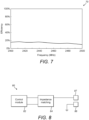
- FIG. 7 is a plot, indicated generally by the reference numeral 70, showing functionality in accordance with an example embodiment.
- the plot 70 shows an efficiency diagram of the second resonance mode antenna.
- FIG. 8 is a block diagram of a circuit, indicated generally by the reference numeral 80, used in an example embodiment.
- the circuit 80 comprises a control module 82, an impedance matching circuit 84, a first connection point 86 and a second connection point 87.
- the control module 82 and the impedance matching circuit 84 may be formed from the circuit elements 36 on the printed circuit board 32 described above.
- the control module 82 is used to generate the antenna signal for transmission.
- the control module 82 may, for example, be configured to transmit data from the aerosol provision device 10 to the remote device 22 described above.
- data such as aerosol device usage data, battery level etc. could be transmitted. These data may be collected and used (e.g. displayed or stored) at the remove device 22.
- the remote device 22 may be a mobile phone having an application that can be used to display information relating to the aerosol provision device 10.
- the first and second connection points 86 and 87 are the first and second connection points referred to in the algorithm 50 discussed above.
- the first contact spring 35a connects the first connection point 86 to ground and the second contact spring 35b connects the output of the impedance matching circuit 84 to the second connection point 87.
- control module 82 can make use of the first and second connection points 86 and 87 for the transmission of an antenna signal (e.g. Bluetooth signal or a WiFi signal).
- an antenna signal e.g. Bluetooth signal or a WiFi signal.
- FIG. 9 is a flow chart showing an algorithm, indicated generally by the reference numeral 90, in accordance with an example embodiment.
- the algorithm 90 starts at operation 92, wherein an antenna signal is generated.
- the antenna signal may be generated by the control module 82.
- impedance matching is provided between the antenna signal generating circuit (the control module 82) and the transmitting antenna (the metal housing 30 or 40).
- the impedance matching is implemented by the impedance matching circuit 84.
- the signal is transmitted, using the metal housing as the antenna.
- the transmission may take the form of a Bluetooth signal or a WiFi signal.
- the first and second connection points 86 and 87 are provided on the inside surface of the metal housing 30 or 40 and may be separated by a defined multiple of a wavelength of transmission of the antenna signal (e.g. one quarter, three-quarters or five-quarters of the wavelength of transmission).
- FIG. 10 is a block diagram of an antenna arrangement, indicated generally by the reference numeral 100, in accordance with an example embodiment.
- the antenna arrangement is a planar inverter F-antenna; other antenna arrangements could be used in other example embodiments.
- the antenna arrangement 100 includes a signal node 101 (such as the signal feed source element 41 described above) a conductor 102 (such as the radiating conductor element 43 described above) and a ground connection 103.
- the ground connection 103 is connected to the conductor 102, for example using a spring such as the first contact spring 35a described above.
- the signal node 101 is connected to the conductor 102, for example using a spring such as the second contact spring 35b described above.
- an antenna signal may be sent from an aerosol provision device 10 (such as an electronic smoking article) to a remote device 22 (such as a mobile communication device).
- the remote device may use the data in many different ways.
- FIG. 11 is a flow chart showing an algorithm, indicated generally by the reference numeral 100, in accordance with an example embodiment.
- the algorithm 110 shows one example use of data that may be obtained by the remote device 22 from the aerosol provision device 10.
- the algorithm 110 starts at operation 112, where a signal is received at the remote device 22 or some other mobile communication device from the aerosol provision device 10, an electronic smoking article or some similar device.
- the location of said aerosol provision device, electronic smoking article or similar device is determined based on the received communications.
- the location determination may take the form of determining the location of the transmission relative to the location of the reception.
- the location determined in operation 114 may be plotted, for example on a display of the remote device or mobile communication device.
- FIG. 12 shows an example user interface, indicated generally by the reference numeral 120, in accordance with an example embodiment.
- the user interface 120 may be output by the remote device 22 or by some other mobile communication device.
- the user interface shows a user location (e.g. a location of the remote device 22) together with an indicator of the position of the aerosol provision device 10 (marked with an "X" in the user interface 120).
- a user location e.g. a location of the remote device 22
- an indicator of the position of the aerosol provision device 10 marked with an "X" in the user interface 120.
- the user interface 120 is provided by way of example only; many alternative display configuration could be provided, including displaying other forms of data.
- a susceptor may be provided as part of the article 201.
- the aerosol provision device 200 when the article 201 is inserted in aerosol provision device, the aerosol provision device 200 may be turned on due to the insertion of the article 201.
- the (inductive) heating elements 203 e.g. inductive heating elements
- the susceptor may be provided as part of the aerosol provision device 200 (e.g. as part of a holder for receiving the article 201).
Landscapes
- Engineering & Computer Science (AREA)
- Computer Networks & Wireless Communication (AREA)
- Details Of Aerials (AREA)
- Support Of Aerials (AREA)
- Transmitters (AREA)
- Structure Of Receivers (AREA)
- Transceivers (AREA)
- Charge And Discharge Circuits For Batteries Or The Like (AREA)
Description
- The present specification relates to an aerosol provision device, in particular to a housing of an aerosol provision device.
- Smoking articles, such as cigarettes, cigars and the like burn tobacco during use to create tobacco smoke. Attempts have been made to provide alternatives to these articles by creating products that release compounds without combusting. For example, tobacco heating devices heat an aerosol provision substrate such as tobacco to form an aerosol by heating, but not burning, the substrate. An aerosol provision device, such as aerosol provision devices known from
TW M 592 171 U US 2016/261020 A1 andCN 110 380 219 A , may be provided with a means for communication, for example for communication with a mobile communication device of a user of the device. There remains a need for further developments in this field. - In a first aspect, this specification describes a metal housing for an aerosol provision device (e.g. a housing for an electronic smoking article), the metal housing comprising: a printed circuit board mounted within the metal housing; a first contact spring providing an electrical connection between a first connection point on an inside of the metal housing and a ground connection of the printed circuit board; and a second contact spring providing an electrical connection between a second connection point on the inside surface of the metal housing and an antenna signal output for providing an antenna signal for transmission by the metal housing (such that the metal housing may be used as an antenna, such as a Bluetooth or WiFi antenna), wherein the metal housing comprises a radiating conductor element extending from a first surface element to a second surface element, wherein the first and second connection points are provided on the radiating conductor element and wherein a distance between the first and second surface elements is at least one quarter of a wavelength of the antenna signal transmission.
- In some example embodiments, the radiating conductor element is an elliptical cylindrical radiating conductor element, the first surface element is a first elliptical surface element and the second surface element is a second elliptical surface element.
- The metal housing may further comprise a signal feed source element and an antenna signal terminal, wherein the antenna signal terminal is connected to the second connection point and the signal feed source element is connected to the antenna signal terminal by the second contact spring.
- The metal housing may further comprise an impedance matching circuit, which impedance matching circuit may be adjustable. The impedance matching circuit may be provided on the printed circuit board.
- The metal housing may further comprise a control module for generating the antenna signal for transmission. The control module may be configured to cause the transmission of data (e.g. device usage data, battery levels etc.). These data may be collected and used (e.g. displayed or stored) by a user's mobile communication device (e.g. an application on the user's phone that is in communication with the aerosol provision device).
- The metal housing may fully enclose the printed circuit board.
- In a second aspect, this specification describes a method comprising: inserting a printed circuit board into a metal housing for an aerosol provision device such that a first contact spring of the printed circuit board provides an electrical connection between a first connection point on an inside of the metal housing and a ground connection of the printed circuit board and a second contact spring of the printed circuit board provides an electrical connection between a second connection point on the inside surface of the metal housing and an antenna signal output for providing an antenna signal for transmission (e.g. a Bluetooth signal or a WiFi signal) by the metal housing, wherein the metal housing comprises a radiating conductor element extending from a first surface element to a second surface element, wherein the first and second connection points are provided on the radiating conductor element and wherein a distance between the first and second surface elements is at least one quarter of a wavelength of the antenna signal transmission. The antenna signal may be used for communications with a mobile communication device. Once inserted, the printed circuit board may be fully enclosed by the metal housing.
- The method may further comprise matching an impedance between the antenna signal generating circuit and the metal housing and may, for example, include adjusting the impedance matching.
- The method may further comprise generating the antenna signal for transmission.
- The antenna signal may be used for locating the aerosol provision device.
- In a third aspect, this specification describes an aerosol provision device (e.g. a non-combustible aerosol provision device) comprising a metal housing including any of the features of the first aspect.
- In a fourth aspect, this specification describes an electronic smoking article comprising an aerosol provision device of the third aspect.
- In a fifth aspect, this specification describes a method comprising using an aerosol provision device of the third aspect or an electronic smoking article of the fourth aspect for communications with a mobile communication device.
- In a sixth aspect, this specification describes a method comprising: receiving communications at a mobile communication device from an aerosol provision device of the third aspect or an electronic smoking article of the fourth aspect; and determining a location of said aerosol provision device or said electronic smoking article based on the received communications. The method may further comprise plotting the determined location on a display of said mobile communication device.
- In a seventh aspect, this specification describes computer-readable instructions which, when executed by computing apparatus, cause the computing apparatus to perform any method as described with reference to the second, fifth or sixth aspects.
- In an eighth aspect, this specification describes a kit of parts comprising an article (e.g. a removable article comprising an aerosol generating material) for use in a non-combustible aerosol generating system, wherein the non-combustible aerosol generating system comprises a metal housing including any of the features of the first aspect described above or a device or system including any of the features of the third or fourth aspects described above.
- Example embodiments will now be described, by way of example only, with reference to the following schematic drawings, in which:
-
FIG. 1 is a block diagram of a non-combustible aerosol provision device in accordance with an example embodiment; -
FIG. 2 is a block diagram of a system in accordance with an example embodiment; -
FIG. 3 is a block diagram of a housing in accordance with an example embodiment; -
FIG. 4 is a block diagram of a housing in accordance with an example that does not have all the claimed features; -
FIG. 5 is a flow chart showing an algorithm in accordance with an example embodiment; -
FIGS. 6 and7 are plots showing functionality in accordance with example embodiments; -
FIG. 8 is a block diagram of a circuit used in an example embodiment; -
FIG. 9 is a flow chart showing an algorithm in accordance with an example embodiment; -
FIG. 10 is a block diagram of an antenna arrangement in accordance an example embodiment; -
FIG. 11 is flow chart showing an algorithm in accordance with an example embodiment; -
FIG. 12 shows an example user interface in accordance with an example embodiment; and -
FIG. 13 is a block diagram of a non-combustible aerosol provision device in accordance with an example embodiment. - As used herein, the term "delivery system" is intended to encompass systems that deliver a substance to a user, and includes:
- combustible aerosol provision systems, such as cigarettes, cigarillos, cigars, and tobacco for pipes or for roll-your-own or for make-your-own cigarettes (whether based on tobacco, tobacco derivatives, expanded tobacco, reconstituted tobacco, tobacco substitutes or other smokable material);
- non-combustible aerosol provision systems that release compounds from an aerosolisable material without combusting the aerosolisable material, such as electronic cigarettes, tobacco heating products, and hybrid systems to generate aerosol using a combination of aerosolisable materials;
- articles comprising aerosolisable material and configured to be used in one of these non-combustible aerosol provision systems; and
- aerosol-free delivery systems, such as lozenges, gums, patches, articles comprising inhalable powders, and smokeless tobacco products such as snus and snuff, which deliver a material to a user without forming an aerosol, wherein the material may or may not comprise nicotine.
- According to the present disclosure, a "combustible" aerosol provision system is one where a constituent aerosolisable material of the aerosol provision system (or component thereof) is combusted or burned in order to facilitate delivery to a user.
- According to the present disclosure, a "non-combustible" aerosol provision system is one where a constituent aerosolisable material of the aerosol provision system (or component thereof) is not combusted or burned in order to facilitate delivery to a user. In embodiments described herein, the delivery system is a non-combustible aerosol provision system, such as a powered non-combustible aerosol provision system.
- In one embodiment, the non-combustible aerosol provision system is an electronic cigarette, also known as a vaping device or electronic nicotine delivery system (END), although it is noted that the presence of nicotine in the aerosolisable material is not a requirement.
- In one embodiment, the non-combustible aerosol provision system is a tobacco heating system, also known as a heat-not-burn system.
- In one embodiment, the non-combustible aerosol provision system is a hybrid system to generate aerosol using a combination of aerosolisable materials, one or a plurality of which may be heated. Each of the aerosolisable materials may be, for example, in the form of a solid, liquid or gel and may or may not contain nicotine. In one embodiment, the hybrid system comprises a liquid or gel aerosolisable material and a solid aerosolisable material. The solid aerosolisable material may comprise, for example, tobacco or a non-tobacco product.
- Typically, the non-combustible aerosol provision system may comprise a non-combustible aerosol provision device and an article for use with the non-combustible aerosol provision system. However, it is envisaged that articles which themselves comprise a means for powering an aerosol generating component may themselves form the non-combustible aerosol provision system.
- In one embodiment, the non-combustible aerosol provision device may comprise a power source and a controller. The power source may be an electric power source or an exothermic power source. In one embodiment, the exothermic power source comprises a carbon substrate which may be energised so as to distribute power in the form of heat to an aerosolisable material or heat transfer material in proximity to the exothermic power source. In one embodiment, the power source, such as an exothermic power source, is provided in the article so as to form the non-combustible aerosol provision.
- In one embodiment, the article for use with the non-combustible aerosol provision device may comprise an aerosolisable material, an aerosol generating component, an aerosol generating area, a mouthpiece, and/or an area for receiving aerosolisable material.
- In one embodiment, the aerosol generating component is a heater capable of interacting with the aerosolisable material so as to release one or more volatiles from the aerosolisable material to form an aerosol. In one embodiment, the aerosol generating component is capable of generating an aerosol from the aerosolisable material without heating. For example, the aerosol generating component may be capable of generating an aerosol from the aerosolisable material without applying heat thereto, for example via one or more of vibrational, mechanical, pressurisation or electrostatic means.
- In one embodiment, the aerosolisable material may comprise an active material, an aerosol forming material and optionally one or more functional materials. The active material may comprise nicotine (optionally contained in tobacco or a tobacco derivative) or one or more other non-olfactory physiologically active materials. A non-olfactory physiologically active material is a material which is included in the aerosolisable material in order to achieve a physiological response other than olfactory perception. The active substance as used herein may be a physiologically active material, which is a material intended to achieve or enhance a physiological response. The active substance may for example be selected from nutraceuticals, nootropics, psychoactives. The active substance may be naturally occurring or synthetically obtained. The active substance may comprise for example nicotine, caffeine, taurine, theine, vitamins such as B6 or B12 or C, melatonin, cannabinoids, or constituents, derivatives, or combinations thereof. The active substance may comprise one or more constituents, derivatives or extracts of tobacco, cannabis or another botanical. In some embodiments, the active substance comprises nicotine. In some embodiments, the active substance comprises caffeine, melatonin or vitamin B12.
- The aerosol forming material may comprise one or more of glycerine, glycerol,propylene glycol, diethylene glycol, triethylene glycol, tetraethylene glycol, 1,3-butylene glycol, erythritol, meso-Erythritol, ethyl vanillate, ethyl laurate, a diethyl suberate, triethyl citrate, triacetin, a diacetin mixture, benzyl benzoate, benzyl phenyl acetate, tributyrin, lauryl acetate, lauric acid, myristic acid, and propylene carbonate.
- The one or more functional materials may comprise one or more of flavours, carriers, pH regulators, stabilizers, and/or antioxidants.
- In one embodiment, the article for use with the non-combustible aerosol provision device may comprise aerosolisable material or an area for receiving aerosolisable material. In one embodiment, the article for use with the non-combustible aerosol provision device may comprise a mouthpiece. The area for receiving aerosolisable material may be a storage area for storing aerosolisable material. For example, the storage area may be a reservoir. In one embodiment, the area for receiving aerosolisable material may be separate from, or combined with, an aerosol generating area.
- Aerosolisable material, which also may be referred to herein as aerosol generating material, is material that is capable of generating aerosol, for example when heated, irradiated or energized in any other way. Aerosolisable material may, for example, be in the form of a solid, liquid or gel which may or may not contain nicotine and/or flavourants. In some embodiments, the aerosolisable material may comprise an "amorphous solid", which may alternatively be referred to as a "monolithic solid" (i.e. non-fibrous). In some embodiments, the amorphous solid may be a dried gel. The amorphous solid is a solid material that may retain some fluid, such as liquid, within it.
- The aerosolisable material may be present on a substrate. The substrate may, for example, be or comprise paper, card, paperboard, cardboard, reconstituted aerosolisable material, a plastics material, a ceramic material, a composite material, glass, a metal, or a metal alloy.
- A consumable is an article comprising or consisting of aerosol-generating material, part or all of which is intended to be consumed during use by a user. A consumable may comprise one or more other components, such as an aerosol-generating material storage area, an aerosol-generating material transfer component, an aerosol generation area, a housing, a wrapper, a mouthpiece, a filter and/or an aerosol-modifying agent. A consumable may also comprise an aerosol generator, such as a heater, that emits heat to cause the aerosol-generating material to generate aerosol in use. The heater may, for example, comprise combustible material, a material heatable by electrical conduction, or a susceptor.
- A susceptor is a material that is heatable by penetration with a varying magnetic field, such as an alternating magnetic field. The susceptor may be an electrically-conductive material, so that penetration thereof with a varying magnetic field causes induction heating of the heating material. The heating material may be magnetic material, so that penetration thereof with a varying magnetic field causes magnetic hysteresis heating of the heating material. The susceptor may be both electrically-conductive and magnetic, so that the susceptor is heatable by both heating mechanisms. The device that is configured to generate the varying magnetic field is referred to as a magnetic field generator, herein.
-
FIG. 1 is a block diagram of a non-combustible aerosol provision device, indicated generally by thereference numeral 10, in accordance with an example embodiment. The aerosol provision device 10 (such as an e-cigarette) comprises amouthpiece 11, a cartridge orpod 12, anatomizer 13, asensor 14, acontrol module 15, a battery 16 (e.g. a rechargeable lithium battery) and an LED 17 (or some other illumination device). Thecontrol module 15 may comprise a microprocessor. - In a use of the
aerosol provision device 10, a user inhales from themouthpiece 11. The cartridge ofpod 12 may store a liquid solution (e.g. of glycerol, flavourings and nicotine). - The
sensor 14 may be an air flow sensor configured to sense the air flow inhaled by a user and may provide an input to thecontrol module 15. Functions of thecontrol module 15 may include controlling theatomizer 13 and theLED 17. Thedevice 10 may use theatomizer 13 to seek to simulate a smoke-like vapour flavour. The LED indicator light 17 may illuminate when used, simulating the fire light during smoking. - The
control module 15 may include a communications means, such as a Bluetooth chip or WiFi chip. The communication means may be integrated into a microprocessor of thecontrol module 15. An antenna (discussed in detail below) enables the communications means to communicate with a remote device (such as a mobile phone, a mobile communication device, a laptop, a computer or some other device), to enable information to be provided to a user. - As discussed in detail below, the antenna may be provided by a metal shell or housing (e.g. a shell, housing or sleeve of the aerosol provision device 10). The antenna may be planar inverted F (PIFA) antenna.
- The
aerosol provision device 10 may include a connector, such as a USB connector (not shown) that enables a connection to be made to a power source for charging abattery 16. - The
aerosol provision device 10 is provided by way of example only; many variants and alternatives are possible. -
FIG. 2 is a block diagram of a system, indicated generally by thereference numeral 20, in accordance with an example embodiment. Thesystem 20 comprises theaerosol provision device 10 and a remote device 22 (i.e. remote from the aerosol provision device). Theremote device 22 may, for example, be a mobile phone, a mobile communication device, a laptop, a computer or a similar device, and may be owned by a user of theaerosol provision device 10. - As indicated above (and discussed in further detail below), the
aerosol provision device 10 has an output that transmits a signal (such as a Bluetooth signal or a WiFi signal). The transmitted signal can be detected by theremote device 22 such that theaerosol provision device 10 can communicate with theremote device 22. In some example embodiments, theremote device 22 is able to transmit to the aerosol provision device 10 (as indicated by the dotted line in the system 20), but this is not essential to all embodiments. - The signal transmitted from the
aerosol provision device 10 to theremote device 22 may be used to transmit information such as how many e-cigarettes a user puffs or the amount of remaining liquid per day. The skilled person will be aware of many other examples of data that may be transmitted from theaerosol provision device 10 to the remote device 22 (or, indeed, data that may be transmitted from theremote device 22 to the aerosol provision device 10). -
FIG. 3 is a block diagram of a housing, indicated generally by thereference numeral 30, in accordance with an example embodiment. Thehousing 30 comprises anouter sleeve 31, such as an aluminium sleeve, which sleeve may provide the exterior of at least some of theaerosol provision device 10 described above. Note that thehousing 30 may be used with alternative aerosol provisioning or generating devices and electronic smoking articles. - As shown in
FIG. 3 , a printedcircuit board 32 and abattery 34 are mounted within themetal housing 30. The electronic components of thecontrol module 15 may be provided on the printedcircuit board 32. Other components may also be provided (such as the atomiser 13). Note that although thebattery 34 is shown below the printedcircuit board 32, this is just one example implementation. The printed circuit board and the battery may, for example, be provided side-by-side. - A
first contact spring 35a provides an electrical connection between a first connection point on an inside of thesleeve 31 and a ground connection of the printed circuit board. Similarly, asecond contact spring 35b provides an electrical connection between a second connection point on the inside surface of thesleeve 31 and an antenna signal output for providing an antenna signal for transmission by the metal housing (such that themetal housing 30 can be used as an antenna). - A plurality of circuit elements, indicated generally by the
reference numeral 36, are shown on the printedcircuit board 32, as discussed further below. -
FIG. 4 is a block diagram of a housing, indicated generally by thereference numeral 40, in accordance with an example that does not have all the claimed features. Thehousing 40 is an example implementation of thehousing 30 described above. Thehousing 40 may be a sleeve. Thehousing 40 may be an elliptical cylindrical shape and may be resilient such that there is some flexibility in the shape of the housing. Thehousing 40 may be shaped dependent on a shape of the aerosol provision device 10 (and may, for example, have a circular, rectangular, elliptical, diamond or any other shape). - The
housing 40 comprises a signalfeed source element 41, anantenna signal terminal 42, a radiatingconductor element 43, afirst surface element 44, asecond surface element 45, a metalground plane element 46 and ametal dome element 47. Theradiating conducting element 43 extends from thefirst surface element 44 to thesecond surface element 45. A distance between the first and second surface elements is at least one quarter of a wavelength of the antenna signal transmission, such that the antenna signal transmission has an acceptable efficiency. - Although not shown in
FIG. 4 the first and second connection points of the metal housing referred to above with respect toFIG. 3 are provided on the radiatingconductor element 43. - In the specific configuration shown in
FIG. 4 , the radiatingconductor element 43 is an elliptical cylindrical radiating conductor element. Similarly, the first andsecond surface elements housing 40 may be shaped dependent on a shape of the aerosol provision device 10 (and may, for example, have a circular, rectangular, elliptical, diamond or any other shape). Similarly, the radiatingconductor element 43 and the first andsecond surface elements housing 40 and may therefore have a circular, rectangular, elliptical, diamond or any other shape. - The signal
feed source element 41 is connected to theantenna signal terminal 42 and theantenna signal terminal 42 is connected to the radiatingconductor element 43. Theantenna signal terminal 42 may be connected to the second connection point described above. More specifically, the signalfeed source element 41 may be connected to theantenna signal terminal 42 or the radiatingconductor element 43 by thesecond contact spring 35b described above. - The radiating
conductor element 43 covers the metalground plane element 46. The metalground plane element 46 can be provided with a Bluetooth chip or a WiFi chip, a battery, a microprocessor, air flow sensors, LED indicators and other components. - Thus, the
housing 40 may enclose some or all of the elements of theaerosol provision device 10 described above. (Note that some of the element of theaerosol provision device 10 may be provided outside thehousing 40 and may, for example, be connected to an exterior of thehousing 40.) - As shown in
FIG. 4 , one end of themetal dome element 47 is connected to the radiatingconductor element 43, and the other end is connected to the metalground plane element 46 which forming a ground, the electrical characteristic is zero ohm. In fact, themetal dome element 47 can be replaced by a contact spring, pogo pin, thimble or similar element. Themetal dome element 47 is therefore an electrical conductor that electrically connects the radiatingconductor element 43 and the metalground plane element 46. The impedance matching of the antenna can be adjusted by adjusting the distance between the position of the signalfeed source element 41 and the position of the metal dome element 47 (e.g. by adjusting the distance between the first and second connection points described above). The signalfeed source element 41 at a resonance point impedance (resistance) of 50 Ω, and the reactance should be close to zero, which can achieve good impedance matching and can thereby stimulate the maximum electromagnetic radiation transmission signal. Thefirst surface element 44 and thesecond surface element 45, both of which are made of electrical materials, can be metal conductors or plastic materials. - The radiating
conductor element 43 can excite a first resonance mode frequency, when the length of thefirst surface element 44 extending from the radiatingconductor element 43 to thesecond surface element 45 is a quarter wavelength of the transmission. Similarly, the radiatingconductor element 43 can excite a second resonance mode frequency, when the length of thefirst surface element 44 extending from the radiatingconductor element 43 to thesecond surface element 45 is three-quarters of the wavelength of transmission. Finally, the radiatingconductor element 43 can excite a third resonance mode frequency, when the length of thefirst surface element 44 extending from the radiatingconductor element 43 to thesecond surface element 45 is five-quarters of the wavelength of transmission. Of course, other resonance modes (e.g. at longer wavelengths) are also possible. Note that in some example embodiments, the second resonance mode frequency may be the preferred transmission mode (as discussed further below). - A distance between the first and second surface elements may be set at one quarter of a wavelength of the antenna signal transmission, as this is a point of high efficiency of the antenna signal transmission. In some example embodiments, there is insufficient design freedom to set the distance between the first and second surface elements with precision. In such cases, it may be sufficient that the distance between the first and second surface elements is at least one quarter of a wavelength of the antenna signal transmission.
- A number of variants to the
housing 40 are possible. For example, thefirst surface element 44 and thesecond surface element 45 may be provided with holes in the surface for some functions such as LED lights, buttons, air inlets or charging docks. -
FIG. 5 is a flow chart showing an algorithm, indicated generally by thereference numeral 50, in accordance with an example embodiment. - The
algorithm 50 starts atoperation 52, where the printedcircuit board 32 is inserted into the metal housing 30 (or the housing 40). - At
operation 54, the insertion of the printedcircuit board 32 continues until thefirst contact spring 35a and thesecond contact spring 35b contact first and second connection points on the inside of the metal housing respectively. In this configuration, thefirst contact spring 35a provides an electrical connection between the first connection point and a ground connection of the printed circuit board and thesecond contact spring 35b provides an electrical connection between the second connection point and an antenna signal output for providing an antenna signal for transmission by the metal housing. - When the
algorithm 50 is complete, the printedcircuit board 32 is fully enclosed within themetal housing -
FIG. 6 is a plot, indicated generally by thereference numeral 60, showing functionality in accordance with an example embodiment. - The
plot 60 shows a measured reflection loss (S11) for transmissions made using themetal housing 40 as an antenna. Theplot 60 clearly shows frequencies at which the loss decreases substantially, these are indicated as a firstresonance mode frequency 62, a secondresonance mode frequency 63 and a thirdresonance mode frequency 64. The centre frequency of the firstresonance mode frequency 62 is 810MHz, the centre frequency of the secondresonance mode frequency 63 is 2430MHz and centre frequency of the three-resonance mode frequency 64 is 4050MHz. The second-resonance mode frequency 63 covers the wireless Bluetooth communication frequency and the WiFi 2.4G communication frequency. Accordingly, themetal housing 40 may use the secondresonance mode frequency 63 for Bluetooth or WiFi transmissions. - In one example embodiment, in the first resonance mode, the length of the
first surface element 44 extending from the radiatingconductor element 43 to thesecond surface element 45 is one quarter of the wavelength of transmission, in the second resonance mode, that length may be three-quarters of the wavelength of transmission, and in the third resonance mode, that length may be five-quarters of the wavelength of transmission. - In the event of a Bluetooth or WiFi signal being transmitted at about 2.4 GHz (having a wavelength of the order of 12.5 centimetres), the first and second surface elements may be separated by a distance of the order of 9.4 centimetres in order to operate in the second resonance mode.
- The structure of the
housing 40 may be adjustable (e.g. during a design phase). For example one or more of the shape, length or thickness of one or more of the radiatingconductor element 43, thefirst surface element 44 and thesecond surface element 45 may be adjustable. Such adjustments may have an impact of the frequencies at which the first, second and third resonance modes occur. -
FIG. 7 is a plot, indicated generally by thereference numeral 70, showing functionality in accordance with an example embodiment. Theplot 70 shows an efficiency diagram of the second resonance mode antenna. -
FIG. 8 is a block diagram of a circuit, indicated generally by thereference numeral 80, used in an example embodiment. - The
circuit 80 comprises acontrol module 82, animpedance matching circuit 84, afirst connection point 86 and asecond connection point 87. Thecontrol module 82 and theimpedance matching circuit 84 may be formed from thecircuit elements 36 on the printedcircuit board 32 described above. - The
control module 82 is used to generate the antenna signal for transmission. Thecontrol module 82 may, for example, be configured to transmit data from theaerosol provision device 10 to theremote device 22 described above. By way of example, data such as aerosol device usage data, battery level etc. could be transmitted. These data may be collected and used (e.g. displayed or stored) at theremove device 22. For example, theremote device 22 may be a mobile phone having an application that can be used to display information relating to theaerosol provision device 10. - The first and second connection points 86 and 87 are the first and second connection points referred to in the
algorithm 50 discussed above. Thus, when the printed circuit board is fully inserted, thefirst contact spring 35a connects thefirst connection point 86 to ground and thesecond contact spring 35b connects the output of theimpedance matching circuit 84 to thesecond connection point 87. - Thus, the
control module 82 can make use of the first and second connection points 86 and 87 for the transmission of an antenna signal (e.g. Bluetooth signal or a WiFi signal). -
FIG. 9 is a flow chart showing an algorithm, indicated generally by thereference numeral 90, in accordance with an example embodiment. - The
algorithm 90 starts atoperation 92, wherein an antenna signal is generated. As discussed above, the antenna signal may be generated by thecontrol module 82. - At
operation 94, impedance matching is provided between the antenna signal generating circuit (the control module 82) and the transmitting antenna (themetal housing 30 or 40). The impedance matching is implemented by theimpedance matching circuit 84. - At
operation 96, the signal is transmitted, using the metal housing as the antenna. The transmission may take the form of a Bluetooth signal or a WiFi signal. - The first and second connection points 86 and 87 are provided on the inside surface of the
metal housing -
FIG. 10 is a block diagram of an antenna arrangement, indicated generally by thereference numeral 100, in accordance with an example embodiment. The antenna arrangement is a planar inverter F-antenna; other antenna arrangements could be used in other example embodiments. - The
antenna arrangement 100 includes a signal node 101 (such as the signalfeed source element 41 described above) a conductor 102 (such as the radiatingconductor element 43 described above) and aground connection 103. - The
ground connection 103 is connected to theconductor 102, for example using a spring such as thefirst contact spring 35a described above. - The
signal node 101 is connected to theconductor 102, for example using a spring such as thesecond contact spring 35b described above. - As discussed above with reference to
FIG. 2 , an antenna signal may be sent from an aerosol provision device 10 (such as an electronic smoking article) to a remote device 22 (such as a mobile communication device). The remote device may use the data in many different ways. - By way of example,
FIG. 11 is a flow chart showing an algorithm, indicated generally by thereference numeral 100, in accordance with an example embodiment. Thealgorithm 110 shows one example use of data that may be obtained by theremote device 22 from theaerosol provision device 10. - The
algorithm 110 starts atoperation 112, where a signal is received at theremote device 22 or some other mobile communication device from theaerosol provision device 10, an electronic smoking article or some similar device. - At
operation 114, the location of said aerosol provision device, electronic smoking article or similar device is determined based on the received communications. The location determination may take the form of determining the location of the transmission relative to the location of the reception. - At
optional operation 116, the location determined inoperation 114 may be plotted, for example on a display of the remote device or mobile communication device. -
FIG. 12 shows an example user interface, indicated generally by thereference numeral 120, in accordance with an example embodiment. Theuser interface 120 may be output by theremote device 22 or by some other mobile communication device. - The user interface shows a user location (e.g. a location of the remote device 22) together with an indicator of the position of the aerosol provision device 10 (marked with an "X" in the user interface 120).
- Of course, the
user interface 120 is provided by way of example only; many alternative display configuration could be provided, including displaying other forms of data. - As discussed above, the
aerosol provision device 10 is described by way of example only; many variants and alternatives are possible. By way of example,FIG. 13 is a block diagram of a non-combustible aerosol provision device, indicated generally by thereference numeral 200, in accordance with an example embodiment. Theaerosol provision device 200 is an example implementation of theaerosol provision device 10 described above. -
FIG. 13 shows theaerosol provision device 200 without an outer cover. Theaerosol provision device 200 may comprise areplaceable article 201 that may be inserted in theaerosol provision device 200 to enable heating of thearticle 201. Theaerosol provision device 100 further comprises anactivation switch 202 that may be used for switching on or switching off theaerosol provision device 200 and a plurality ofheating elements air tube extenders air tube extenders - The
heating elements article 201. Alternatively, theheating elements heating elements aerosol provision device 100 may comprise one or more heating elements. - A susceptor may be provided as part of the
article 201. In an example embodiment, when thearticle 201 is inserted in aerosol provision device, theaerosol provision device 200 may be turned on due to the insertion of thearticle 201. When theaerosol provision device 100 is turned on, the (inductive) heating elements 203 (e.g. inductive heating elements) may cause thearticle 201 to be heated (e.g. inductively heated) through the susceptor. In an alternative embodiment, the susceptor may be provided as part of the aerosol provision device 200 (e.g. as part of a holder for receiving the article 201).
Claims (15)
- A metal housing (30, 40) for an aerosol provision device, the metal housing comprising:a printed circuit board (32) mounted within the metal housing;a first contact spring (35a) providing an electrical connection between a first connection point on an inside of the metal housing and a ground connection of the printed circuit board; anda second contact spring (35b) providing an electrical connection between a second connection point on the inside surface of the metal housing and an antenna signal output for providing an antenna signal for transmission by the metal housing,wherein the metal housing comprises a radiating conductor element (43) extending from a first surface element (44) to a second surface element (45), wherein the first and second connection points are provided on the radiating conductor element and wherein a distance between the first and second surface elements is at least one quarter of a wavelength of the antenna signal transmission.
- A metal housing as claimed in claim 1, wherein the radiating conductor element (43) is an elliptical cylindrical radiating conductor element, the first surface element (44) is a first elliptical surface element and the second surface element (45) is a second elliptical surface element.
- A metal housing as claimed in claim 1 or claim 2, further comprising:a signal feed source element (41) and an antenna signal terminal (42), wherein the antenna signal terminal is connected to the second connection point and the signal feed source element is connected to the antenna signal terminal by the second contact spring (35b); and/ora control module (82) for generating the antenna signal for transmission.
- A metal housing as claimed in any one of the preceding claims, further comprising an impedance matching circuit (84), wherein the impedance matching circuit is optionally adjustable.
- A metal housing as claimed in any one of the preceding claims, wherein:the metal housing is a housing for an electronic smoking article; and/orthe metal housing fully encloses the printed circuit board.
- A metal housing as claimed in any one of the preceding claims, wherein the antenna signal for transmission is a Bluetooth signal or a WiFi signal.
- A method comprising:inserting (52) a printed circuit board (32) into a metal housing (30, 40) for an aerosol provision device such that a first contact spring (35a) of the printed circuit board provides an electrical connection between a first connection point on an inside of the metal housing and a ground connection of the printed circuit board and a second contact spring (35b) of the printed circuit board provides an electrical connection between a second connection point on the inside surface of the metal housing and an antenna signal output for providing an antenna signal for transmission by the metal housing,wherein the metal housing comprises a radiating conductor element extending from a first surface element to a second surface element, wherein the first and second connection points are provided on the radiating conductor element and wherein a distance between the first and second surface elements is at least one quarter of a wavelength of the antenna signal transmission.
- A method as claimed in claim 7, further comprising matching an impedance between the antenna signal generating circuit and the metal housing, wherein the method optionally further comprises adjusting the impedance matching.
- A method as claimed in claim 7 or claim 8, further comprising:generating the antenna signal for transmission; and/orusing the antenna signal for communications with a mobile communication device.
- A method as claimed in any one of claims 7 to 9, wherein:the antenna signal for transmission is a Bluetooth signal or a WiFi signal; and/orthe antenna signal is used for locating the aerosol provision device.
- An aerosol provision device comprising a metal housing as claimed in any one of claims 1 to 6.
- An electronic smoking article comprising an aerosol provision device as claimed in claim 11.
- A method comprising using an aerosol provision device as claimed in claim 11 or an electronic smoking article as claimed in claim 12 for communications with a mobile communication device.
- A method comprising:receiving communications at a mobile communication device from an aerosol provision device as claimed in claim 11 or an electronic smoking article as claimed in claim 12; anddetermining a location of said aerosol provision device or said electronic smoking article based on the received communications.
- A method as claimed in claim 14, further comprising plotting the determined location on a display of said mobile communication device.
Applications Claiming Priority (2)
| Application Number | Priority Date | Filing Date | Title |
|---|---|---|---|
| GBGB2008076.8A GB202008076D0 (en) | 2020-05-29 | 2020-05-29 | Aerosol provision device |
| PCT/GB2021/051287 WO2021240156A1 (en) | 2020-05-29 | 2021-05-27 | Aerosol provision device |
Publications (2)
| Publication Number | Publication Date |
|---|---|
| EP4158730A1 EP4158730A1 (en) | 2023-04-05 |
| EP4158730B1 true EP4158730B1 (en) | 2025-07-02 |
Family
ID=71526293
Family Applications (1)
| Application Number | Title | Priority Date | Filing Date |
|---|---|---|---|
| EP21731570.4A Active EP4158730B1 (en) | 2020-05-29 | 2021-05-27 | Aerosol provision device |
Country Status (10)
| Country | Link |
|---|---|
| US (1) | US12484638B2 (en) |
| EP (1) | EP4158730B1 (en) |
| JP (1) | JP7577134B2 (en) |
| KR (1) | KR20230003013A (en) |
| CA (1) | CA3173379A1 (en) |
| GB (1) | GB202008076D0 (en) |
| MX (1) | MX2022015051A (en) |
| PL (1) | PL4158730T3 (en) |
| UA (1) | UA128499C2 (en) |
| WO (1) | WO2021240156A1 (en) |
Families Citing this family (10)
| Publication number | Priority date | Publication date | Assignee | Title |
|---|---|---|---|---|
| TWI750887B (en) * | 2020-11-06 | 2021-12-21 | 和碩聯合科技股份有限公司 | Antenna module |
| GB202114035D0 (en) * | 2021-09-30 | 2021-11-17 | Nicoventures Holdings Ltd | Housing for an aerosol provision device |
| KR102763749B1 (en) * | 2021-12-22 | 2025-02-07 | 주식회사 케이티앤지 | Aerosol generating device comprising planar inverted-f antenna, and user authentication method |
| JP7841124B2 (en) * | 2022-05-17 | 2026-04-06 | ケーティー アンド ジー コーポレイション | Aerosol generator |
| US20250386866A1 (en) * | 2022-06-30 | 2025-12-25 | Nicoventures Trading Limited | Aerosol provision device |
| CN115363258B (en) * | 2022-08-24 | 2025-07-29 | 深圳市拓普联科技术股份有限公司 | Electronic cigarette |
| WO2024046876A1 (en) * | 2022-08-31 | 2024-03-07 | Imperial Tobacco Limited | Control assembly for aerosol generating device |
| KR20240066685A (en) * | 2022-11-08 | 2024-05-16 | 주식회사 케이티앤지 | Module for Wireless Communitation and Generating Aearosol |
| WO2025126354A1 (en) * | 2023-12-13 | 2025-06-19 | 日本たばこ産業株式会社 | Flavor inhaler |
| WO2026088257A1 (en) * | 2024-10-21 | 2026-04-30 | 日本たばこ産業株式会社 | Flavor inhaler and flavor inhalation system |
Family Cites Families (9)
| Publication number | Priority date | Publication date | Assignee | Title |
|---|---|---|---|---|
| JPH042488Y2 (en) * | 1986-09-05 | 1992-01-28 | ||
| US5173274A (en) * | 1991-08-16 | 1992-12-22 | Southwest Research Institute | Flash liquid aerosol production method and appartus |
| JP2006352673A (en) | 2005-06-17 | 2006-12-28 | Toshiba Corp | Communication terminal and antenna mounting method |
| WO2015175715A1 (en) * | 2014-05-13 | 2015-11-19 | Loec, Inc. | Method, system and device for inductively charging batteries in electronic cigarettes |
| US10027016B2 (en) * | 2015-03-04 | 2018-07-17 | Rai Strategic Holdings Inc. | Antenna for an aerosol delivery device |
| US20160261020A1 (en) * | 2015-03-04 | 2016-09-08 | R.J. Reynolds Tobacco Company | Antenna for an Aerosol Delivery Device |
| GB201517087D0 (en) | 2015-09-28 | 2015-11-11 | Nicoventures Holdings Ltd | Vaping policy alert system and method |
| CN110380219B (en) | 2019-08-16 | 2020-09-29 | 昆山联滔电子有限公司 | Electronic device |
| CN210350079U (en) | 2019-09-03 | 2020-04-17 | 上海莫仕连接器有限公司 | Antenna device |
-
2020
- 2020-05-29 GB GBGB2008076.8A patent/GB202008076D0/en not_active Ceased
-
2021
- 2021-05-27 US US18/000,186 patent/US12484638B2/en active Active
- 2021-05-27 WO PCT/GB2021/051287 patent/WO2021240156A1/en not_active Ceased
- 2021-05-27 CA CA3173379A patent/CA3173379A1/en active Pending
- 2021-05-27 EP EP21731570.4A patent/EP4158730B1/en active Active
- 2021-05-27 JP JP2022570148A patent/JP7577134B2/en active Active
- 2021-05-27 KR KR1020227041081A patent/KR20230003013A/en not_active Ceased
- 2021-05-27 PL PL21731570.4T patent/PL4158730T3/en unknown
- 2021-05-27 MX MX2022015051A patent/MX2022015051A/en unknown
- 2021-05-27 UA UAA202203931A patent/UA128499C2/en unknown
Also Published As
| Publication number | Publication date |
|---|---|
| GB202008076D0 (en) | 2020-07-15 |
| WO2021240156A1 (en) | 2021-12-02 |
| PL4158730T3 (en) | 2025-08-18 |
| US20230200455A1 (en) | 2023-06-29 |
| CA3173379A1 (en) | 2021-12-02 |
| US12484638B2 (en) | 2025-12-02 |
| JP7577134B2 (en) | 2024-11-01 |
| UA128499C2 (en) | 2024-07-24 |
| JP2023525388A (en) | 2023-06-15 |
| EP4158730A1 (en) | 2023-04-05 |
| MX2022015051A (en) | 2023-01-04 |
| KR20230003013A (en) | 2023-01-05 |
Similar Documents
| Publication | Publication Date | Title |
|---|---|---|
| US12484638B2 (en) | Aerosol provision device | |
| CN107529831A (en) | antenna for aerosol delivery device | |
| US12532922B2 (en) | Aerosol provision device | |
| AU2021287271B2 (en) | Aerosol provision device | |
| US20240407469A1 (en) | Housing for an aerosol provision device | |
| US12349741B2 (en) | Aerosol provision device | |
| US20250024896A1 (en) | Charging device having an antenna | |
| CA3240219A1 (en) | Radio frequency transmitter for providing power to an aerosol provision device | |
| CN119679202A (en) | Aerosol supply system | |
| CN119679201A (en) | Aerosol supply system | |
| CA3240217A1 (en) | Charging device | |
| WO2025061982A1 (en) | Aerosol provision device | |
| CA3240221A1 (en) | A transmitter module for radio frequency charging |
Legal Events
| Date | Code | Title | Description |
|---|---|---|---|
| STAA | Information on the status of an ep patent application or granted ep patent |
Free format text: STATUS: UNKNOWN |
|
| STAA | Information on the status of an ep patent application or granted ep patent |
Free format text: STATUS: THE INTERNATIONAL PUBLICATION HAS BEEN MADE |
|
| PUAI | Public reference made under article 153(3) epc to a published international application that has entered the european phase |
Free format text: ORIGINAL CODE: 0009012 |
|
| STAA | Information on the status of an ep patent application or granted ep patent |
Free format text: STATUS: REQUEST FOR EXAMINATION WAS MADE |
|
| 17P | Request for examination filed |
Effective date: 20221108 |
|
| AK | Designated contracting states |
Kind code of ref document: A1 Designated state(s): AL AT BE BG CH CY CZ DE DK EE ES FI FR GB GR HR HU IE IS IT LI LT LU LV MC MK MT NL NO PL PT RO RS SE SI SK SM TR |
|
| P01 | Opt-out of the competence of the unified patent court (upc) registered |
Effective date: 20230505 |
|
| P02 | Opt-out of the competence of the unified patent court (upc) changed |
Effective date: 20230604 |
|
| DAV | Request for validation of the european patent (deleted) | ||
| DAX | Request for extension of the european patent (deleted) | ||
| GRAP | Despatch of communication of intention to grant a patent |
Free format text: ORIGINAL CODE: EPIDOSNIGR1 |
|
| STAA | Information on the status of an ep patent application or granted ep patent |
Free format text: STATUS: GRANT OF PATENT IS INTENDED |
|
| RIC1 | Information provided on ipc code assigned before grant |
Ipc: A24F 40/10 20200101ALN20250117BHEP Ipc: A24F 40/65 20200101ALI20250117BHEP Ipc: H01Q 1/36 20060101ALI20250117BHEP Ipc: H01Q 1/27 20060101ALI20250117BHEP Ipc: A24F 40/40 20200101ALI20250117BHEP Ipc: H01Q 9/04 20060101AFI20250117BHEP |
|
| INTG | Intention to grant announced |
Effective date: 20250213 |
|
| GRAS | Grant fee paid |
Free format text: ORIGINAL CODE: EPIDOSNIGR3 |
|
| GRAA | (expected) grant |
Free format text: ORIGINAL CODE: 0009210 |
|
| STAA | Information on the status of an ep patent application or granted ep patent |
Free format text: STATUS: THE PATENT HAS BEEN GRANTED |
|
| AK | Designated contracting states |
Kind code of ref document: B1 Designated state(s): AL AT BE BG CH CY CZ DE DK EE ES FI FR GB GR HR HU IE IS IT LI LT LU LV MC MK MT NL NO PL PT RO RS SE SI SK SM TR |
|
| REG | Reference to a national code |
Ref country code: GB Ref legal event code: FG4D |
|
| REG | Reference to a national code |
Ref country code: CH Ref legal event code: EP |
|
| REG | Reference to a national code |
Ref country code: DE Ref legal event code: R096 Ref document number: 602021033367 Country of ref document: DE |
|
| REG | Reference to a national code |
Ref country code: IE Ref legal event code: FG4D |
|
| REG | Reference to a national code |
Ref country code: NL Ref legal event code: MP Effective date: 20250702 |
|
| PG25 | Lapsed in a contracting state [announced via postgrant information from national office to epo] |
Ref country code: PT Free format text: LAPSE BECAUSE OF FAILURE TO SUBMIT A TRANSLATION OF THE DESCRIPTION OR TO PAY THE FEE WITHIN THE PRESCRIBED TIME-LIMIT Effective date: 20251103 |
|
| PG25 | Lapsed in a contracting state [announced via postgrant information from national office to epo] |
Ref country code: NL Free format text: LAPSE BECAUSE OF FAILURE TO SUBMIT A TRANSLATION OF THE DESCRIPTION OR TO PAY THE FEE WITHIN THE PRESCRIBED TIME-LIMIT Effective date: 20250702 |
|
| REG | Reference to a national code |
Ref country code: AT Ref legal event code: MK05 Ref document number: 1810363 Country of ref document: AT Kind code of ref document: T Effective date: 20250702 |
|
| PG25 | Lapsed in a contracting state [announced via postgrant information from national office to epo] |
Ref country code: IS Free format text: LAPSE BECAUSE OF FAILURE TO SUBMIT A TRANSLATION OF THE DESCRIPTION OR TO PAY THE FEE WITHIN THE PRESCRIBED TIME-LIMIT Effective date: 20251102 |
|
| PG25 | Lapsed in a contracting state [announced via postgrant information from national office to epo] |
Ref country code: NO Free format text: LAPSE BECAUSE OF FAILURE TO SUBMIT A TRANSLATION OF THE DESCRIPTION OR TO PAY THE FEE WITHIN THE PRESCRIBED TIME-LIMIT Effective date: 20251002 |
|
| REG | Reference to a national code |
Ref country code: LT Ref legal event code: MG9D |
|
| PG25 | Lapsed in a contracting state [announced via postgrant information from national office to epo] |
Ref country code: AT Free format text: LAPSE BECAUSE OF FAILURE TO SUBMIT A TRANSLATION OF THE DESCRIPTION OR TO PAY THE FEE WITHIN THE PRESCRIBED TIME-LIMIT Effective date: 20250702 |
|
| PG25 | Lapsed in a contracting state [announced via postgrant information from national office to epo] |
Ref country code: FI Free format text: LAPSE BECAUSE OF FAILURE TO SUBMIT A TRANSLATION OF THE DESCRIPTION OR TO PAY THE FEE WITHIN THE PRESCRIBED TIME-LIMIT Effective date: 20250702 |
|
| PG25 | Lapsed in a contracting state [announced via postgrant information from national office to epo] |
Ref country code: HR Free format text: LAPSE BECAUSE OF FAILURE TO SUBMIT A TRANSLATION OF THE DESCRIPTION OR TO PAY THE FEE WITHIN THE PRESCRIBED TIME-LIMIT Effective date: 20250702 |
|
| PG25 | Lapsed in a contracting state [announced via postgrant information from national office to epo] |
Ref country code: GR Free format text: LAPSE BECAUSE OF FAILURE TO SUBMIT A TRANSLATION OF THE DESCRIPTION OR TO PAY THE FEE WITHIN THE PRESCRIBED TIME-LIMIT Effective date: 20251003 |
|
| PG25 | Lapsed in a contracting state [announced via postgrant information from national office to epo] |
Ref country code: CZ Free format text: LAPSE BECAUSE OF FAILURE TO SUBMIT A TRANSLATION OF THE DESCRIPTION OR TO PAY THE FEE WITHIN THE PRESCRIBED TIME-LIMIT Effective date: 20250702 Ref country code: SE Free format text: LAPSE BECAUSE OF FAILURE TO SUBMIT A TRANSLATION OF THE DESCRIPTION OR TO PAY THE FEE WITHIN THE PRESCRIBED TIME-LIMIT Effective date: 20250702 |
|
| PG25 | Lapsed in a contracting state [announced via postgrant information from national office to epo] |
Ref country code: LV Free format text: LAPSE BECAUSE OF FAILURE TO SUBMIT A TRANSLATION OF THE DESCRIPTION OR TO PAY THE FEE WITHIN THE PRESCRIBED TIME-LIMIT Effective date: 20250702 |
|
| PG25 | Lapsed in a contracting state [announced via postgrant information from national office to epo] |
Ref country code: BG Free format text: LAPSE BECAUSE OF FAILURE TO SUBMIT A TRANSLATION OF THE DESCRIPTION OR TO PAY THE FEE WITHIN THE PRESCRIBED TIME-LIMIT Effective date: 20250702 |
|
| PG25 | Lapsed in a contracting state [announced via postgrant information from national office to epo] |
Ref country code: RS Free format text: LAPSE BECAUSE OF FAILURE TO SUBMIT A TRANSLATION OF THE DESCRIPTION OR TO PAY THE FEE WITHIN THE PRESCRIBED TIME-LIMIT Effective date: 20251002 |
|
| PG25 | Lapsed in a contracting state [announced via postgrant information from national office to epo] |
Ref country code: ES Free format text: LAPSE BECAUSE OF FAILURE TO SUBMIT A TRANSLATION OF THE DESCRIPTION OR TO PAY THE FEE WITHIN THE PRESCRIBED TIME-LIMIT Effective date: 20250702 |
|
| PG25 | Lapsed in a contracting state [announced via postgrant information from national office to epo] |
Ref country code: SM Free format text: LAPSE BECAUSE OF FAILURE TO SUBMIT A TRANSLATION OF THE DESCRIPTION OR TO PAY THE FEE WITHIN THE PRESCRIBED TIME-LIMIT Effective date: 20250702 |
|
| PG25 | Lapsed in a contracting state [announced via postgrant information from national office to epo] |
Ref country code: DK Free format text: LAPSE BECAUSE OF FAILURE TO SUBMIT A TRANSLATION OF THE DESCRIPTION OR TO PAY THE FEE WITHIN THE PRESCRIBED TIME-LIMIT Effective date: 20250702 |
|
| PG25 | Lapsed in a contracting state [announced via postgrant information from national office to epo] |
Ref country code: EE Free format text: LAPSE BECAUSE OF FAILURE TO SUBMIT A TRANSLATION OF THE DESCRIPTION OR TO PAY THE FEE WITHIN THE PRESCRIBED TIME-LIMIT Effective date: 20250702 Ref country code: SK Free format text: LAPSE BECAUSE OF FAILURE TO SUBMIT A TRANSLATION OF THE DESCRIPTION OR TO PAY THE FEE WITHIN THE PRESCRIBED TIME-LIMIT Effective date: 20250702 |
|
| PLBE | No opposition filed within time limit |
Free format text: ORIGINAL CODE: 0009261 |
|
| STAA | Information on the status of an ep patent application or granted ep patent |
Free format text: STATUS: NO OPPOSITION FILED WITHIN TIME LIMIT |