EP4158618B1 - Sonobuoy volumetric array deployment module - Google Patents
Sonobuoy volumetric array deployment module Download PDFInfo
- Publication number
- EP4158618B1 EP4158618B1 EP21798474.9A EP21798474A EP4158618B1 EP 4158618 B1 EP4158618 B1 EP 4158618B1 EP 21798474 A EP21798474 A EP 21798474A EP 4158618 B1 EP4158618 B1 EP 4158618B1
- Authority
- EP
- European Patent Office
- Prior art keywords
- deployment
- cable
- sensors
- sensor array
- deployment module
- Prior art date
- Legal status (The legal status is an assumption and is not a legal conclusion. Google has not performed a legal analysis and makes no representation as to the accuracy of the status listed.)
- Active
Links
Images



Classifications
-
- G—PHYSICS
- G10—MUSICAL INSTRUMENTS; ACOUSTICS
- G10K—SOUND-PRODUCING DEVICES; METHODS OR DEVICES FOR PROTECTING AGAINST, OR FOR DAMPING, NOISE OR OTHER ACOUSTIC WAVES IN GENERAL; ACOUSTICS NOT OTHERWISE PROVIDED FOR
- G10K11/00—Methods or devices for transmitting, conducting or directing sound in general; Methods or devices for protecting against, or for damping, noise or other acoustic waves in general
- G10K11/004—Mounting transducers, e.g. provided with mechanical moving or orienting device
- G10K11/006—Transducer mounting in underwater equipment, e.g. sonobuoys
-
- F—MECHANICAL ENGINEERING; LIGHTING; HEATING; WEAPONS; BLASTING
- F03—MACHINES OR ENGINES FOR LIQUIDS; WIND, SPRING, OR WEIGHT MOTORS; PRODUCING MECHANICAL POWER OR A REACTIVE PROPULSIVE THRUST, NOT OTHERWISE PROVIDED FOR
- F03G—SPRING, WEIGHT, INERTIA OR LIKE MOTORS; MECHANICAL-POWER PRODUCING DEVICES OR MECHANISMS, NOT OTHERWISE PROVIDED FOR OR USING ENERGY SOURCES NOT OTHERWISE PROVIDED FOR
- F03G7/00—Mechanical-power-producing mechanisms, not otherwise provided for or using energy sources not otherwise provided for
- F03G7/06—Mechanical-power-producing mechanisms, not otherwise provided for or using energy sources not otherwise provided for using expansion or contraction of bodies due to heating, cooling, moistening, drying or the like
- F03G7/061—Mechanical-power-producing mechanisms, not otherwise provided for or using energy sources not otherwise provided for using expansion or contraction of bodies due to heating, cooling, moistening, drying or the like characterised by the actuating element
- F03G7/0614—Mechanical-power-producing mechanisms, not otherwise provided for or using energy sources not otherwise provided for using expansion or contraction of bodies due to heating, cooling, moistening, drying or the like characterised by the actuating element using shape memory elements
- F03G7/06145—Springs
-
- G—PHYSICS
- G01—MEASURING; TESTING
- G01S—RADIO DIRECTION-FINDING; RADIO NAVIGATION; DETERMINING DISTANCE OR VELOCITY BY USE OF RADIO WAVES; LOCATING OR PRESENCE-DETECTING BY USE OF THE REFLECTION OR RERADIATION OF RADIO WAVES; ANALOGOUS ARRANGEMENTS USING OTHER WAVES
- G01S7/00—Details of systems according to groups G01S13/00, G01S15/00, G01S17/00
- G01S7/52—Details of systems according to groups G01S13/00, G01S15/00, G01S17/00 of systems according to group G01S15/00
- G01S7/521—Constructional features
-
- G—PHYSICS
- G01—MEASURING; TESTING
- G01V—GEOPHYSICS; GRAVITATIONAL MEASUREMENTS; DETECTING MASSES OR OBJECTS; TAGS
- G01V1/00—Seismology; Seismic or acoustic prospecting or detecting
- G01V1/16—Receiving elements for seismic signals; Arrangements or adaptations of receiving elements
- G01V1/20—Arrangements of receiving elements, e.g. geophone pattern
-
- G—PHYSICS
- G01—MEASURING; TESTING
- G01V—GEOPHYSICS; GRAVITATIONAL MEASUREMENTS; DETECTING MASSES OR OBJECTS; TAGS
- G01V1/00—Seismology; Seismic or acoustic prospecting or detecting
- G01V1/16—Receiving elements for seismic signals; Arrangements or adaptations of receiving elements
- G01V1/20—Arrangements of receiving elements, e.g. geophone pattern
- G01V1/201—Constructional details of seismic cables, e.g. streamers
-
- G—PHYSICS
- G01—MEASURING; TESTING
- G01V—GEOPHYSICS; GRAVITATIONAL MEASUREMENTS; DETECTING MASSES OR OBJECTS; TAGS
- G01V1/00—Seismology; Seismic or acoustic prospecting or detecting
- G01V1/38—Seismology; Seismic or acoustic prospecting or detecting specially adapted for water-covered areas
- G01V1/3843—Deployment of seismic devices, e.g. of streamers
-
- G—PHYSICS
- G10—MUSICAL INSTRUMENTS; ACOUSTICS
- G10K—SOUND-PRODUCING DEVICES; METHODS OR DEVICES FOR PROTECTING AGAINST, OR FOR DAMPING, NOISE OR OTHER ACOUSTIC WAVES IN GENERAL; ACOUSTICS NOT OTHERWISE PROVIDED FOR
- G10K11/00—Methods or devices for transmitting, conducting or directing sound in general; Methods or devices for protecting against, or for damping, noise or other acoustic waves in general
- G10K11/004—Mounting transducers, e.g. provided with mechanical moving or orienting device
- G10K11/006—Transducer mounting in underwater equipment, e.g. sonobuoys
- G10K11/008—Arrays of transducers
-
- H—ELECTRICITY
- H04—ELECTRIC COMMUNICATION TECHNIQUE
- H04B—TRANSMISSION
- H04B11/00—Transmission systems employing ultrasonic, sonic or infrasonic waves
-
- B—PERFORMING OPERATIONS; TRANSPORTING
- B63—SHIPS OR OTHER WATERBORNE VESSELS; RELATED EQUIPMENT
- B63B—SHIPS OR OTHER WATERBORNE VESSELS; EQUIPMENT FOR SHIPPING
- B63B22/00—Buoys
- B63B2022/006—Buoys specially adapted for measuring or watch purposes
-
- B—PERFORMING OPERATIONS; TRANSPORTING
- B63—SHIPS OR OTHER WATERBORNE VESSELS; RELATED EQUIPMENT
- B63B—SHIPS OR OTHER WATERBORNE VESSELS; EQUIPMENT FOR SHIPPING
- B63B22/00—Buoys
- B63B22/003—Buoys adapted for being launched from an aircraft or water vehicle;, e.g. with brakes deployed in the water
Definitions
- the invention relates to a system and method of packing and deploying sensor arrays.
- An exemplary sensor array includes a hydrophone array.
- a hydrophone array may be implemented in a sonobuoy that is dropped or ejected from an aircraft or a ship. The sonobuoy and the array may be dropped into an environment for acoustic observation. For example, the sonobuoy may be dropped in the ocean for underwater acoustic research.
- a sonobuoy may be used in military applications, such as in anti-submarine warfare.
- the sensor array is deployed from the sonobuoy. During deployment, the sensor array may expand from a compacted structure to an expanded structure in which the sensor array is operable to perform the intended function, such as underwater surveillance.
- Sonobuoys typically have a small size such that stowage and deployment of the hydrophone array presents challenges.
- Prior attempts to package and deploy hydrophone arrays include using rigid structures to support the shape of the array and external actuation devices such as motors, pumps and extra batteries. Using the rigid structures and external actuation devices may be a disadvantage for small-sized sonobuoys due to space constraints.
- Another disadvantage of using the rigid structures is that the structures provide limited deployment options for the sensors and thus limited directionality for the sensor array.
- US 3 539 979 A discloses a marine seismic detector array with a self erector which comprises: (a) a pair of plates having a central shaft extendin therebetween, (b) a rotatable hub mounted on said shaft, (c) a plurality of resilient strips prestressed to a nonplanar transverse configuration each anchored at one end thereof to the surface of said hub and wound onto said hub, (d) a like plurality of guides secured between said plates radially spaced from said hub and through which said strips extend, (e) cable means for supporting said plates at a preselected depth at a marine listening station, (f) a seismic sensor secured to the free end of each of said strips with said strips normally coiled about said hub, (g) a restraining band encircling the sensors to prevent said strips from unwinding from said hub, and (h) actuating means for removing said band to permit said strips to unwind from said hub for the support of said sensors in an array wherein each of said sensors is spaced from the axi
- US 3 558 369 A discloses that TiNi-base alloys, particularly those near stoichiometric TiNi composition, have applications as self-erecting aerospace and hydrospace components, low acoustic noise machine mountings and devices, prestressed bindings and reinforcements, stored energy tools, energy converters, temperature actuated devices (switches, fire alarms, etc.), clock mechanisms, cryogenic components.
- a deployment module includes a support shell that is configured to retain a cable of the sensor array separately from sensors of the sensor array and an expandable deployment body formed of a superelastic shape memory alloy that uses superelasticity and stored energy for deployment of the sensor array.
- the deployment body is removed from the support shell and the sensors are subsequently pulled out of the support shell. The deployment body then expands and holds the cable to retain the three-dimensional volumetric shape of the deployed sensor array.
- the deployment module is modular in that a plurality of deployment sub-modules are axially stacked to form the deployment module.
- Each deployment sub-module includes a deployment body and a support shell. During deployment, the support shells are sequentially emptied of the sensors until all of the sensors are deployed.
- the deployment module may be vertically deployed such that the deployment sub-modules are deployed starting from an uppermost deployment sub-module and continuing until a lowermost deployment sub-module is deployed or vice versa.
- the support shell may be formed using additive manufacturing and is formed to have spaced walls that define discrete slots for retaining the cable. Using the support shell prevents hockling or tangling of the cable during stowage and deployment. The shape of the support shell also positions each sensor on top of the walls by way of each sensor being seated after wrapping a segment of the cable in the walls until an open seat for a sensor is reached.
- the deployment body may include a central hub and springs that are spirally wound around the central hub during stowage. One end of each spring is secured to the central hub. During deployment, the entire deployment body spins due to the superelasticity and stored spring energy of the springs, such that each spring is unwound and straightens radially outwardly to a normal shape of the spring. The extended end of the spring has an arm secured to the spring that engages the cable to maintain the shape of the sensor array.
- the sensors of the sensor array may be formed using a micro inductive welding process. Clamshell portions are fused together to form a clamshell body that surrounds a flexible piezo element of each sensor. A plastic membrane is sealed onto the clamshell body to cover the piezo element. Using micro inductive welding enables a rapid sealing process that results in watertight, pressure tolerant, and precise sealing for the sensor electronics.
- the invention provides a deployment module for a sensor array having a plurality of sensors and a cable connecting the plurality of sensors comprising: a deployment body formed of a shape memory alloy that is expandable to hold the cable and retain a shape of the sensor array after deployment; and a support shell configured to support the sensor array and the expandable deployment body in a stowage state before deployment, the support shell having spaced walls configured to retain the cable separately from the plurality of sensors, wherein the spaced walls define discrete slots that each accommodate a segment of the cable corresponding to one of the plurality of sensors.
- the deployment body is formed of a superelastic material having stored spring energy when in the stowage state.
- the deployment body is spinnable to release the spring energy whereby the deployment body expands from a compacted shape to an expanded shape.
- the deployment body includes a central hub and a plurality of springs that each have a fixed end secured to the central hub.
- deployment body includes a plurality of arms that are secured to opposite ends of the plurality of springs relative to the central hub and are configured to engage the cable.
- the plurality of arms includes clamping portions to engage the cable.
- the central hub has a plurality of blades, wherein the fixed end of each of the plurality of springs is held between two adjacent blades of the plurality of blades.
- the deployment module includes a plurality of deployment bodies and a plurality of support shells, wherein the plurality of support shells and the plurality of deployment bodies are axially stacked.
- the deployment module includes a central electro-mechanical cable that supports each of the plurality of deployment bodies.
- the principles described herein have particular application in systems used for sensing extremely large environments or environments that are not easily accessible. Examples of environments in which a sensing system or array may be used include underwater, air, and space.
- the deployment module and method disclosed herein may be used for packing and deploying sensors in a particular environment.
- Military applications such as anti-submarine warfare, or non-military applications, such as underwater acoustic research applications, may be suitable applications.
- a sonobuoy that includes a hydrophone array having any size may be suitable, and more particularly, a small-size or "A-size" sonobuoy for deploying a hydrophone array may be suitable.
- the hydrophone array may be deployed into the ocean from any suitable platform, such as an aircraft, sea vessel, or land vehicle.
- the deployment module and method disclosed herein may be used with many other sensor systems, environments, and platforms.
- a deployment module 20 for a sensor array 22 includes a deployment body 24 and a support shell 26. As shown in Fig. 1 , the deployment module 20 has a stowage state in which the sensor array 22 and the deployment body 24 are supported in the support shell 26. The deployment body 24 and the sensor array 22 may be axially stacked in the support shell 26 along a central axis C.
- the deployment module 20 may be cylindrical in shape such that the central axis C is a longitudinal axis of the deployment module 20. Shapes other than cylindrical for the deployment module 20 may be suitable, such as spherical or rectangular, and the shape may be dependent on the application.
- the sensor array 22 includes a plurality of sensors 28 and a cable 30 that connects the plurality of sensors 28 to form the sensor array 22.
- the sensor array 22 may be a hydrophone array and the sensors 28 may be hydrophones, such as piezoelectric transducers.
- Other sensors may be suitable for the sensor array 22, such as other acoustic sensors or optical sensors. Sensors that are configured to detect other environmental characteristics may also be suitable.
- suitable sensors include sensors that detect pressure, temperature, or depth or distance.
- Each sensor 28 is connected to an adjacent sensor by a segment or length of the cable extending between axial ends 32 of the sensors.
- Fig. 2 shows an exploded view of the deployment module 20.
- the support shell 26 includes a plurality of spaced walls 34 that are configured to retain the cable 30 separately from the plurality of sensors 28 during the stowage state.
- the walls 34 are formed in a spiraled or leaved pattern.
- Discrete slots 36 are defined between the walls 34 and each discrete slot 36 accommodates a segment of the cable 30 that extends between two of the plurality of sensors 28.
- the cable 30 is nested in the walls 34.
- Each wall 34 may form a loop 38 proximate a center 40 of the support shell 26 that engages a corresponding loop of an adjacent wall 34, such that the support shell 26 has a plurality of loops 38 proximate the center 40.
- Using the support shell 26 is advantageous in preventing hockling or tangling of the cable 30 during both stowage and deployment.
- a plurality of axially extending tabs 42 are formed on an outermost wall 44 and may be circumferentially spaced by recessed windows 46 about the support shell 26.
- the axially extending tabs 42 and the recessed windows 46 are used to provide access to the sensors 28, such as during packing the sensor array 22 into the deployment module 20.
- Any suitable manufacturing process and material may be used to form the support shell 26.
- the support shell 26 may be formed as an integral and monolithic body.
- An additive manufacturing process may be suitable to form the support shell 26.
- Other manufacturing methods, such as injection molding, may also be suitable.
- the support shell 26 may be formed of a plastic material.
- Other materials, such as other polymer materials or metal materials may also be suitable. The materials may be dependent on the environment of an intended application for the deployment module 20.
- the support shell 26 is further advantageous in positioning the plurality of sensors 28 during the stowage state and deployment.
- the sensors 28 may rest on top of the walls 34.
- the walls 34 are formed to accommodate a predetermined length of the cable 30 such that after a predetermined length of the cable 30 is inserted into a corresponding discrete slot 36 of the support shell 26, a sensor 28 at the end of the predetermined length of the cable 30 reaches an empty seat on top of the walls 34.
- the empty seat is adjacent another sensor 28 that was previously placed on top of the walls 34.
- the sensor 28 is then seated at the specific location on the plurality of walls 34 and another predetermined length of the cable 30 is inserted into another corresponding discrete slot 36 until the next empty seat for the sensor 28 is reached.
- the sensors 28 When seated on the walls 34, the sensors 28 are spaced by a predetermined distance and the sensors 28 may be held in position via the cable 30 being wrapped around the walls 34.
- the sensors 28 are placed independently and in succession such that a first sensor 28a is placed in the support shell 26, a segment of the cable 30 is inserted in a corresponding one of the discrete slots 36, another sensor 28b is placed on the support shell 26 adjacent the first sensor 28a, another segment of the cable 30 is inserted in another discrete slot 36, and so on.
- the placing of the sensors 28 and insertion of the cable 30 occurs alternately until the support shell 26 is fully accommodated.
- the support shell 26 may be sized to accommodate any number of sensors 28 of the sensor array 22 and the number may be dependent on the application. Between five and ten sensors 28 may be supported by the support shell 26. Fewer than five and more than ten sensors may be suitable for other exemplary applications.
- the support shell 26 may be sized up or down for different applications. The size of the support shell 26 may be selected to accommodate a predetermined sensor array 22 using a minimal volume.
- the shape of the support shell 26 may be formed to accommodate the sensors 28 in a one-by-one alignment such that each sensor 28 is arranged between two other sensors 28. In other embodiments, the support shell 26 may be formed to accommodate the sensors 28 in a two-by-two alignment in which a pair of sensors is adjacent two other pairs of sensors. When the sensors 28 are seated in the support shell 26, the sensors 28 may be uniformly oriented. As shown in Figs. 1 and 2 , the sensors 28 may have angled orientations relative to each other, such that a maximum number of sensors 28 are accommodated in the support shell 26. Other arrangements of the sensors 28 may also be suitable.
- the deployment body 24 is expandable and is configured to deploy the sensor array 22 from the support shell 26 without using an external actuation device. The expansion may occur radially outwardly.
- the deployment body 24 expands via the material properties of the material of the deployment body 24.
- the material may be a superelastic shape memory alloy spring that retains spring energy during the stowage state. Due to the superelasticity of the shape memory alloy and the stored spring energy, the deployment body 24 is configured to expand from a contracted shape, as shown in Figs. 1 and 2 , to an expanded shape that is a regular or normal shape of the spring.
- the self-contained deployment body 24 is particularly advantageous for small-sized sonobuoys in which space is constrained.
- the superelasticity of the shape memory alloy may be formed to achieve between 5 and 15% recoverable strain, as compared with conventional shape memory alloys that rely on externally applied joule heat for actuation.
- the deployment body 24 does not require additional activation devices for expansion.
- the shape memory alloy may be formed to activate in response to heat.
- the deployment body 24 is configured to engage the cable 30 to hold the sensor array 22 in a deployed arrangement such that the expansion of the deployment body 24 may occur radially outwardly.
- the precise shape of the deployment body 24 is dependent on the application and many different shapes may be suitable.
- the deployment body 24 may be cylindrical in shape.
- the cylindrical deployment body 24 may spin to expand from the contracted shape to the expanded shape, via the superelasticity of the shape memory alloy and the stored spring energy.
- the deployment body 24 may be formed of a central hub 48 and a plurality of springs 50 that are formed of the shape memory alloy.
- Each spring 50 has an end secured to the central hub 48 and an arm 52 that is secured to an opposite end of the spring 50 relative to the central hub 48.
- the spring 50 may always have an end secured to the central hub 48 during stowage and when deployed.
- Each arm 52 includes a cable engaging end 54 that is opposite a spring securing end 56 at which the arm 52 receives the spring 50.
- the cable engaging end 54 may be formed of clamping portions 58 that engage the cable 30 for securing the deployment body 24 and the cable 30.
- the arm 52 may have any suitable shape.
- the arm 52 may be cylindrical in shape.
- the springs 50 are spirally wound in two-dimensions about the central hub 48 to form a cylindrical shape and each arm 52 is circumferentially spaced about an outer peripheral surface 60 defined by the wound springs 50.
- the central hub 48 may be fan-shaped with a plurality of blades 62.
- Each spring 50 has a fixed end 64 that is held between adjacent blades 62.
- the fixed end 64 remains secured to the central hub 48 and the body of the spring 50 expands or straightens out such that the spring 50 moves to a normal or regular shape of the spring 50.
- the straight or unconstrained shape of the spring 50 holds the cable 30 that is engaged by the spring 50 in the three-dimensional shape.
- Other arrangements of the spring 50 may be suitable.
- the deployment body 24 may be formed to have a single spring coil or counterrotating springs.
- the exemplary sensor 28 includes a flexible piezo element 66 for sensing acoustic energy.
- the piezo element 66 may have any suitable shape, such as a disc shape. Voltage of the sensor 28 is generated by straining the piezo element 66.
- the sensor 28 includes a clamshell body 68 formed of two clamshell halves or portions 68a, 68b that are fused together to surround the piezo element 66 in a compact arrangement.
- the clamshell body 68 may be formed of any suitable material for protecting the internal electronics of the sensor 28.
- An exemplary material includes thermoplastic.
- the sensors 28 may be formed using any suitable manufacturing process.
- An example of a suitable manufacturing process includes micro inductive welding (MIW), such that a plurality of MIW susceptors 70 are formed between the clamshell portions 68a, 68b.
- MIW micro inductive welding
- a plastic membrane 72 is sealed onto the clamshell body 68 over the piezo element 66 to seal the sensor 28.
- Any suitable material may be used for the plastic membrane 72, such as a laminated polyethylene material.
- the plastic membrane 72 may have any suitable shape, such as a cylindrical shape.
- the arrangement of the sensor 28 is particularly advantageous in protecting the internal electronics of the sensor 28 using watertight and pressure resistant sealing that is provided by the MIW.
- the sensor 28 may further include a telemetry circuit card assembly (CCA) 74 supported by the clamshell body 68 and connected to radially outwardly electro-mechanical cable terminations 76 of the sensor 28 via electrical connectors 78.
- the telemetry CCA 74 is used to provide data from the sensor 28 to a receiver that may be located remotely from the deployed sensor array 22.
- MIW susceptors may also be formed between the clamshell body 68 and the electro-mechanical cable terminations 76.
- the electro-mechanical cable terminations 76 are plugged into the clamshell body 68 and are each connected to the cable 30 for connecting each sensor 28 to the cable 30.
- Each sensor 28 may include two electro-mechanical cable terminations 76 that are mirrored on opposite sides of the sensor 28.
- Each electro-mechanical cable termination 76 supports both of the clamshell portions 68a, 68b. Using the electro-mechanical cable terminations 76 is advantageous in enabling the sensors 28 to lay flat in the support shell 26 while enabling the cable 30 to be routed into the discrete slots 36, as compared with conventional hydrophone arrangements in which the cable extends in an axial orientation.
- MIW is advantageous in that the welding provides an effective seal between the elements in the sensor 28, such as between the clamshell portions 68a, 68b, between the plastic membrane 72 and the clamshell body 68, and between the clamshell body 68 and the cable 30.
- MIW is used to rapidly and precisely fuse materials via a non-contact method as compared with conventional sensor forming methods that include potting hydrophones and cables with thermoset urethanes or shrink tubes to seal against water intrusion.
- MIW also eliminates the need for additional sealing elements, such as o-rings.
- a deployment module 80 includes a plurality of deployment sub-modules 20a, 20b, 20c that are axially stacked. Each deployment sub-module 20a, 20b, 20c may have the same features as the deployment module 20 shown in Figs. 1 and 2 .
- the deployment module 80 includes any number of deployment sub-modules 20a, 20b, 20c and the number of deployment sub-modules may be dependent on the application. Between four and ten deployment sub-modules may be suitable. Fewer than four and more than ten deployment sub-modules may be suitable in other applications.
- the deployment module 80 may have a height that is between 25 and 101 centimeters (between 10 and 40 inches).
- the number of deployment sub-modules may be selected based on the size of the sensor array 22 to be accommodated by the deployment module 80.
- Each deployment sub-module 20a, 20b, 20c includes a separate support shell 26 and each support shell 26 may be formed to have the same height and diameter.
- the deployment module 80 includes a plurality of deployment bodies 24 that each correspond to one of the deployment sub-modules 20a, 20b, 20c such that each deployment sub-module 20a, 20b, 20c is separately deployed in succession.
- Fig. 4 also shows each arm 52 of the deployment body 24 engaging a corresponding segment of the cable 30.
- the deployment sub-modules 20a, 20b, 20c are sequentially deployed and within each deployment sub-module 20a, 20b, 20c, the sensor array 22 is sequentially deployed.
- the deployment body 24 of a corresponding deployment sub-module 20a, 20b, 20c is first removed from the support shell 26 and the sensor array 22 is subsequently pulled out of the support shell 26.
- One of the plurality of sensors 28 is pulled out of the support shell 26, which is followed by pulling out a segment of the cable 30 from a corresponding one of the walls 34 of the support shell 26, which is followed by subsequently pulling out another sensor 28 arranged at the opposite end of the segment of the cable 30.
- the removal of the sensors 28 and the cable 30 from the support shell 26 continues in an alternating manner until the support shell 26 is emptied of the sensor array 22.
- three or more meters of cable 30 may be deployed per second.
- the support shell 26 of the corresponding deployment sub-module 20a, 20b, 20c may be displaced and the deployment body 24 of an axially adjacent deployment sub-module 20a, 20b, 20c is then deployed.
- the support shell 26 may be displaced into the environment, or the support shell 26 may be recoverable for future use.
- the deployment sequence may continue for each deployment sub-module 20a, 20b, 20c until all of the deployment sub-modules 20a, 20b, 20c are emptied and the entire sensor array 22 is deployed.
- the deployment module 80 has a vertical orientation during deployment, such that an uppermost deployment sub-module 20a is first deployed and the remaining deployment sub-modules 20b, 20c are deployed until a lowermost deployment sub-module 20c is emptied.
- deployment of the deployment sub-modules 20a, 20b, 20c occurs from the lowermost deployment sub-module 20c and continues upwardly to the uppermost deployment sub-module 20a.
- the deployment module 80 during deployment is shown.
- the sensor array 22 has a vertical orientation and a three-dimensional volumetric shape in which the sensors 28 are radially spaced.
- the deployed shape of the sensor array 22 may have a diameter that is between 15 and 25 times the diameter of the deployment module 80 when in the stowage state.
- the deployment body 24 is in the expanded shape in which springs 50a arranged at a deployed end of the deployment module 80 are straightened out relative to the central hub 48 and extend between the central hub 48 and the cable 30. The stiffness of the springs 50a being in their regular shape holds the segments of the cable 30 in the vertical orientation.
- the springs 50b at an opposite end of the deployment module 80 are shown during deployment in which the springs 50b are straightening out from the wound structure to move to the structure in which the springs 50a are shown.
- the cable 30 extends between all the sensors 28 of the sensor array 22 such that the cable 30 is continuous.
- a central electro-mechanical cable 82 is provided as a strength member that retains an axial spacing of the central hubs 48 for each spring 50a, 50b.
- the central electro-mechanical cable 82 defines the central axis of the deployed sensor array 22.
- Power for the cable 30 may also be provided by the central electro-mechanical cable 82 via a portion of the cable 30 being connected to the central electro-mechanical cable 82.
- the central electro-mechanical cable 82 may extend an entire axial length of the deployed sensor array 22. Accordingly, using the deployment module 80 enables a three-dimensional volumetric arrangement that provides directionality of the sensors 24, as compared with a conventional line array or other sensor arrays that be limited in flexibility of the deployed shape for the sensor array. In an exemplary embodiment, after operation of the sensor array 22 is ceased, the entire deployment module 80 may be recoverable and able to be repackaged and re-deployed.
- Fig. 6 shows the deployment module 20, 80 being deployed from a platform 84 that is shown as an aircraft.
- the platform 84 may be a sea vessel or land vehicle.
- the packing module 20, 80 may be arranged in a sonobuoy 86 that is deployed from the platform 84.
- Fig. 7 shows the deployment module 80 and the deployed sensor array 22 after deployment from a sea vessel 88, or after the packing module 20, 80 is deployed from an aircraft and connected to a sea vessel 88.
- the sensor array 80 is a volumetric array such that the sensors 28 and the cable 30 are arranged in a vertically extending three-dimensional arrangement.
- the sensor array 22 is operable for the intended application when in the three-dimensional arrangement.
- the sonobuoy 86 including the deployment module 20, 80 is deployed by the platform 84, such as the aircraft shown in Fig. 6 , toward the water.
- a release mechanism may be provided for the initial release of the deployment module 20, 80 from the platform.
- the weighted portion 92 or another bottom portion of the deployment module 80 may also include a battery pack to power the sensor array 22.
- the battery pack may be in communication with the central electro-mechanical cable 82 for supplying power to the cable 30.
- Electronics and radio may also be provided for processing data, such as telemetry data, that is received from the sensor array 22.
- the data may be communicated to the sea vessel 88 via the cables 30 through the central electro-mechanical cable 82 and up to a main control system located in the sea vessel 88.
- the control system receiving data from the sensor array 22 may be located proximate the sensor array 22 or remote from the sensor array 22.
- Fig. 8 shows a flowchart for a method 100 of forming a sensor deployment module, such as the deployment modules 20, 80 shown in Fig. 1 and 4 .
- Step 102 of the method 100 includes forming a sensor array 22 having a plurality of sensors 28 and a cable 30 connecting the plurality of sensors 28 using a micro inductive welding process.
- Step 102 may include fusing clamshell bodies 68a, 68b together over a flexible piezo element 66 to form an enclosed clamshell body 68 for each of the plurality of sensors 28, sealing a plastic membrane 72 onto the clamshell body 68 over the flexible piezo element 66, and sealing the cable 30 to electro-mechanical cable terminations 76 of each of the plurality of sensors 28 (shown in Fig. 3 ).
- Step 104 of the method 100 includes forming an expandable deployment body 24 and step 104 may include forming the expandable deployment body 24 of a shape memory alloy.
- Step 106 of the method 100 includes forming a support shell 26 using an additive manufacturing process and step 106 may include forming the support shell 26 of a plastic material having spaced walls 34 configured to retain the cable 30 separately from the plurality of sensors 28.
- Step 108 of the method 100 includes arranging the sensor array 22 and the expandable deployment body 24 in the support shell 26 for stowage before deployment.
- Step 110 of the method may include forming a plurality of expandable deployment bodies 24 and a plurality of support shells 26, and axially stacking the plurality of support shells 26 and the plurality of expandable deployment bodies 24.
Landscapes
- Engineering & Computer Science (AREA)
- Physics & Mathematics (AREA)
- Life Sciences & Earth Sciences (AREA)
- Acoustics & Sound (AREA)
- Chemical & Material Sciences (AREA)
- Combustion & Propulsion (AREA)
- Remote Sensing (AREA)
- General Physics & Mathematics (AREA)
- Multimedia (AREA)
- Computer Networks & Wireless Communication (AREA)
- Mechanical Engineering (AREA)
- Environmental & Geological Engineering (AREA)
- Geophysics (AREA)
- General Life Sciences & Earth Sciences (AREA)
- Geology (AREA)
- Signal Processing (AREA)
- Aviation & Aerospace Engineering (AREA)
- Ocean & Marine Engineering (AREA)
- Radar, Positioning & Navigation (AREA)
- General Engineering & Computer Science (AREA)
- Oceanography (AREA)
- Testing Or Calibration Of Command Recording Devices (AREA)
- Measurement Of Velocity Or Position Using Acoustic Or Ultrasonic Waves (AREA)
- Laminated Bodies (AREA)
Description
- The invention relates to a system and method of packing and deploying sensor arrays.
- Various applications may use sensor arrays. An exemplary sensor array includes a hydrophone array. A hydrophone array may be implemented in a sonobuoy that is dropped or ejected from an aircraft or a ship. The sonobuoy and the array may be dropped into an environment for acoustic observation. For example, the sonobuoy may be dropped in the ocean for underwater acoustic research. A sonobuoy may be used in military applications, such as in anti-submarine warfare. After the sonobuoy reaches the intended environment, the sensor array is deployed from the sonobuoy. During deployment, the sensor array may expand from a compacted structure to an expanded structure in which the sensor array is operable to perform the intended function, such as underwater surveillance.
- Sonobuoys typically have a small size such that stowage and deployment of the hydrophone array presents challenges. Prior attempts to package and deploy hydrophone arrays include using rigid structures to support the shape of the array and external actuation devices such as motors, pumps and extra batteries. Using the rigid structures and external actuation devices may be a disadvantage for small-sized sonobuoys due to space constraints. Another disadvantage of using the rigid structures is that the structures provide limited deployment options for the sensors and thus limited directionality for the sensor array.
-
US 3 539 979 A discloses a marine seismic detector array with a self erector which comprises: (a) a pair of plates having a central shaft extendin therebetween, (b) a rotatable hub mounted on said shaft, (c) a plurality of resilient strips prestressed to a nonplanar transverse configuration each anchored at one end thereof to the surface of said hub and wound onto said hub, (d) a like plurality of guides secured between said plates radially spaced from said hub and through which said strips extend, (e) cable means for supporting said plates at a preselected depth at a marine listening station, (f) a seismic sensor secured to the free end of each of said strips with said strips normally coiled about said hub, (g) a restraining band encircling the sensors to prevent said strips from unwinding from said hub, and (h) actuating means for removing said band to permit said strips to unwind from said hub for the support of said sensors in an array wherein each of said sensors is spaced from the axis of said hub. -
US 3 558 369 A discloses that TiNi-base alloys, particularly those near stoichiometric TiNi composition, have applications as self-erecting aerospace and hydrospace components, low acoustic noise machine mountings and devices, prestressed bindings and reinforcements, stored energy tools, energy converters, temperature actuated devices (switches, fire alarms, etc.), clock mechanisms, cryogenic components. - To enable both compact stowage of a sensor array and expansion of the sensor array into a three-dimensional volumetric array shape that enables improved directionality of the sensor array during operation, a deployment module according to claim 1 is provided. The deployment module includes a support shell that is configured to retain a cable of the sensor array separately from sensors of the sensor array and an expandable deployment body formed of a superelastic shape memory alloy that uses superelasticity and stored energy for deployment of the sensor array. During deployment, the deployment body is removed from the support shell and the sensors are subsequently pulled out of the support shell. The deployment body then expands and holds the cable to retain the three-dimensional volumetric shape of the deployed sensor array.
- The deployment module is modular in that a plurality of deployment sub-modules are axially stacked to form the deployment module. Each deployment sub-module includes a deployment body and a support shell. During deployment, the support shells are sequentially emptied of the sensors until all of the sensors are deployed. The deployment module may be vertically deployed such that the deployment sub-modules are deployed starting from an uppermost deployment sub-module and continuing until a lowermost deployment sub-module is deployed or vice versa.
- The support shell may be formed using additive manufacturing and is formed to have spaced walls that define discrete slots for retaining the cable. Using the support shell prevents hockling or tangling of the cable during stowage and deployment. The shape of the support shell also positions each sensor on top of the walls by way of each sensor being seated after wrapping a segment of the cable in the walls until an open seat for a sensor is reached.
- The deployment body may include a central hub and springs that are spirally wound around the central hub during stowage. One end of each spring is secured to the central hub. During deployment, the entire deployment body spins due to the superelasticity and stored spring energy of the springs, such that each spring is unwound and straightens radially outwardly to a normal shape of the spring. The extended end of the spring has an arm secured to the spring that engages the cable to maintain the shape of the sensor array.
- The sensors of the sensor array may be formed using a micro inductive welding process. Clamshell portions are fused together to form a clamshell body that surrounds a flexible piezo element of each sensor. A plastic membrane is sealed onto the clamshell body to cover the piezo element. Using micro inductive welding enables a rapid sealing process that results in watertight, pressure tolerant, and precise sealing for the sensor electronics.
- The invention provides a deployment module for a sensor array having a plurality of sensors and a cable connecting the plurality of sensors comprising: a deployment body formed of a shape memory alloy that is expandable to hold the cable and retain a shape of the sensor array after deployment; and a support shell configured to support the sensor array and the expandable deployment body in a stowage state before deployment, the support shell having spaced walls configured to retain the cable separately from the plurality of sensors, wherein the spaced walls define discrete slots that each accommodate a segment of the cable corresponding to one of the plurality of sensors.
- According to an embodiment, the deployment body is formed of a superelastic material having stored spring energy when in the stowage state.
- According to an embodiment, the deployment body is spinnable to release the spring energy whereby the deployment body expands from a compacted shape to an expanded shape.
- According to an embodiment, the deployment body includes a central hub and a plurality of springs that each have a fixed end secured to the central hub.
- According to an embodiment, deployment body includes a plurality of arms that are secured to opposite ends of the plurality of springs relative to the central hub and are configured to engage the cable.
- According to an embodiment, the plurality of arms includes clamping portions to engage the cable.
- According to an embodiment, the central hub has a plurality of blades, wherein the fixed end of each of the plurality of springs is held between two adjacent blades of the plurality of blades.
- According to an embodiment, the deployment module includes a plurality of deployment bodies and a plurality of support shells, wherein the plurality of support shells and the plurality of deployment bodies are axially stacked.
- According to an embodiment, the deployment module includes a central electro-mechanical cable that supports each of the plurality of deployment bodies.
- To the accomplishment of the foregoing and related ends, the invention comprises the features hereinafter fully described and pointed out in the claims. The following description and the annexed drawings set forth in detail certain illustrative embodiments of the invention. These embodiments are indicative, however, of but a few of the various ways in which the principles of the invention may be employed within the scope of the invention, as defined by the claims. Other objects, advantages and novel features of the invention will become apparent from the following detailed description of the invention when considered in conjunction with the drawings.
- The annexed drawings, which are not necessarily to scale, show various aspects of the invention.
-
Fig. 1 shows an oblique view of a deployment module for a sensor array according to an exemplary embodiment of the present application. -
Fig. 2 shows an exploded oblique view of the deployment module ofFig. 1 . -
Fig. 3 shows an oblique view of a sensor assembly of the sensor array ofFig. 1 according to an exemplary embodiment. -
Fig. 4 shows a deployment module including a plurality of deployment sub-modules according to an exemplary embodiment of the present application. -
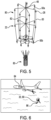
Fig. 5 shows the deployment module ofFig. 4 during deployment. -
Fig. 6 shows an exemplary application in which a sonobuoy is delivered from a platform and includes the deployment module ofFig. 1 . -
Fig. 7 shows an exemplary application in which the sensor array is deployed from the deployment module ofFig. 1 . -
Fig. 8 shows a flowchart illustrating a method of forming a deployment module such as the deployment module ofFig. 1 . - The principles described herein have particular application in systems used for sensing extremely large environments or environments that are not easily accessible. Examples of environments in which a sensing system or array may be used include underwater, air, and space. The deployment module and method disclosed herein may be used for packing and deploying sensors in a particular environment. Military applications, such as anti-submarine warfare, or non-military applications, such as underwater acoustic research applications, may be suitable applications. In an exemplary application, a sonobuoy that includes a hydrophone array having any size may be suitable, and more particularly, a small-size or "A-size" sonobuoy for deploying a hydrophone array may be suitable. The hydrophone array may be deployed into the ocean from any suitable platform, such as an aircraft, sea vessel, or land vehicle. The deployment module and method disclosed herein may be used with many other sensor systems, environments, and platforms.
- Referring first to
Figs. 1 and2 , adeployment module 20 for asensor array 22 includes adeployment body 24 and asupport shell 26. As shown inFig. 1 , thedeployment module 20 has a stowage state in which thesensor array 22 and thedeployment body 24 are supported in thesupport shell 26. Thedeployment body 24 and thesensor array 22 may be axially stacked in thesupport shell 26 along a central axis C. Thedeployment module 20 may be cylindrical in shape such that the central axis C is a longitudinal axis of thedeployment module 20. Shapes other than cylindrical for thedeployment module 20 may be suitable, such as spherical or rectangular, and the shape may be dependent on the application. - The
sensor array 22 includes a plurality ofsensors 28 and acable 30 that connects the plurality ofsensors 28 to form thesensor array 22. In an exemplary embodiment, thesensor array 22 may be a hydrophone array and thesensors 28 may be hydrophones, such as piezoelectric transducers. Other sensors may be suitable for thesensor array 22, such as other acoustic sensors or optical sensors. Sensors that are configured to detect other environmental characteristics may also be suitable. For example, suitable sensors include sensors that detect pressure, temperature, or depth or distance. Eachsensor 28 is connected to an adjacent sensor by a segment or length of the cable extending between axial ends 32 of the sensors. -
Fig. 2 shows an exploded view of thedeployment module 20. Thesupport shell 26 includes a plurality of spacedwalls 34 that are configured to retain thecable 30 separately from the plurality ofsensors 28 during the stowage state. Thewalls 34 are formed in a spiraled or leaved pattern.Discrete slots 36 are defined between thewalls 34 and eachdiscrete slot 36 accommodates a segment of thecable 30 that extends between two of the plurality ofsensors 28. When retained in thewalls 34, thecable 30 is nested in thewalls 34. Eachwall 34 may form aloop 38 proximate acenter 40 of thesupport shell 26 that engages a corresponding loop of anadjacent wall 34, such that thesupport shell 26 has a plurality ofloops 38 proximate thecenter 40. Using thesupport shell 26 is advantageous in preventing hockling or tangling of thecable 30 during both stowage and deployment. - A plurality of axially extending
tabs 42 are formed on anoutermost wall 44 and may be circumferentially spaced by recessedwindows 46 about thesupport shell 26. Theaxially extending tabs 42 and the recessedwindows 46 are used to provide access to thesensors 28, such as during packing thesensor array 22 into thedeployment module 20. Any suitable manufacturing process and material may be used to form thesupport shell 26. Thesupport shell 26 may be formed as an integral and monolithic body. An additive manufacturing process may be suitable to form thesupport shell 26. Other manufacturing methods, such as injection molding, may also be suitable. Thesupport shell 26 may be formed of a plastic material. Other materials, such as other polymer materials or metal materials, may also be suitable. The materials may be dependent on the environment of an intended application for thedeployment module 20. - The
support shell 26 is further advantageous in positioning the plurality ofsensors 28 during the stowage state and deployment. Thesensors 28 may rest on top of thewalls 34. Thewalls 34 are formed to accommodate a predetermined length of thecable 30 such that after a predetermined length of thecable 30 is inserted into a correspondingdiscrete slot 36 of thesupport shell 26, asensor 28 at the end of the predetermined length of thecable 30 reaches an empty seat on top of thewalls 34. The empty seat is adjacent anothersensor 28 that was previously placed on top of thewalls 34. Thesensor 28 is then seated at the specific location on the plurality ofwalls 34 and another predetermined length of thecable 30 is inserted into another correspondingdiscrete slot 36 until the next empty seat for thesensor 28 is reached. - When seated on the
walls 34, thesensors 28 are spaced by a predetermined distance and thesensors 28 may be held in position via thecable 30 being wrapped around thewalls 34. Thesensors 28 are placed independently and in succession such that afirst sensor 28a is placed in thesupport shell 26, a segment of thecable 30 is inserted in a corresponding one of thediscrete slots 36, anothersensor 28b is placed on thesupport shell 26 adjacent thefirst sensor 28a, another segment of thecable 30 is inserted in anotherdiscrete slot 36, and so on. The placing of thesensors 28 and insertion of thecable 30 occurs alternately until thesupport shell 26 is fully accommodated. - The
support shell 26 may be sized to accommodate any number ofsensors 28 of thesensor array 22 and the number may be dependent on the application. Between five and tensensors 28 may be supported by thesupport shell 26. Fewer than five and more than ten sensors may be suitable for other exemplary applications. Thesupport shell 26 may be sized up or down for different applications. The size of thesupport shell 26 may be selected to accommodate apredetermined sensor array 22 using a minimal volume. - The shape of the
support shell 26 may be formed to accommodate thesensors 28 in a one-by-one alignment such that eachsensor 28 is arranged between twoother sensors 28. In other embodiments, thesupport shell 26 may be formed to accommodate thesensors 28 in a two-by-two alignment in which a pair of sensors is adjacent two other pairs of sensors. When thesensors 28 are seated in thesupport shell 26, thesensors 28 may be uniformly oriented. As shown inFigs. 1 and2 , thesensors 28 may have angled orientations relative to each other, such that a maximum number ofsensors 28 are accommodated in thesupport shell 26. Other arrangements of thesensors 28 may also be suitable. - The
deployment body 24 is expandable and is configured to deploy thesensor array 22 from thesupport shell 26 without using an external actuation device. The expansion may occur radially outwardly. Thedeployment body 24 expands via the material properties of the material of thedeployment body 24. The material may be a superelastic shape memory alloy spring that retains spring energy during the stowage state. Due to the superelasticity of the shape memory alloy and the stored spring energy, thedeployment body 24 is configured to expand from a contracted shape, as shown inFigs. 1 and2 , to an expanded shape that is a regular or normal shape of the spring. - Using the self-contained
deployment body 24 is particularly advantageous for small-sized sonobuoys in which space is constrained. The superelasticity of the shape memory alloy may be formed to achieve between 5 and 15% recoverable strain, as compared with conventional shape memory alloys that rely on externally applied joule heat for actuation. Thus, thedeployment body 24 does not require additional activation devices for expansion. In other exemplary embodiments of thedeployment body 24, such as in embodiments intended to be used in air environments, the shape memory alloy may be formed to activate in response to heat. - The
deployment body 24 is configured to engage thecable 30 to hold thesensor array 22 in a deployed arrangement such that the expansion of thedeployment body 24 may occur radially outwardly. The precise shape of thedeployment body 24 is dependent on the application and many different shapes may be suitable. In an exemplary embodiment, thedeployment body 24 may be cylindrical in shape. Thecylindrical deployment body 24 may spin to expand from the contracted shape to the expanded shape, via the superelasticity of the shape memory alloy and the stored spring energy. Thedeployment body 24 may be formed of acentral hub 48 and a plurality ofsprings 50 that are formed of the shape memory alloy. - Each
spring 50 has an end secured to thecentral hub 48 and anarm 52 that is secured to an opposite end of thespring 50 relative to thecentral hub 48. Thespring 50 may always have an end secured to thecentral hub 48 during stowage and when deployed. Eacharm 52 includes acable engaging end 54 that is opposite aspring securing end 56 at which thearm 52 receives thespring 50. Thecable engaging end 54 may be formed of clampingportions 58 that engage thecable 30 for securing thedeployment body 24 and thecable 30. Thearm 52 may have any suitable shape. For example, thearm 52 may be cylindrical in shape. - In the stowage state, the
springs 50 are spirally wound in two-dimensions about thecentral hub 48 to form a cylindrical shape and eacharm 52 is circumferentially spaced about an outerperipheral surface 60 defined by the wound springs 50. Thecentral hub 48 may be fan-shaped with a plurality ofblades 62. Eachspring 50 has a fixedend 64 that is held betweenadjacent blades 62. When thedeployment body 24 is expanded, thefixed end 64 remains secured to thecentral hub 48 and the body of thespring 50 expands or straightens out such that thespring 50 moves to a normal or regular shape of thespring 50. The straight or unconstrained shape of thespring 50 holds thecable 30 that is engaged by thespring 50 in the three-dimensional shape. Other arrangements of thespring 50 may be suitable. For example, thedeployment body 24 may be formed to have a single spring coil or counterrotating springs. - Referring now to
Fig. 3 , an exemplary embodiment of thesensor 28 of thesensor assembly 22 is shown. Theexemplary sensor 28 includes a flexiblepiezo element 66 for sensing acoustic energy. Thepiezo element 66 may have any suitable shape, such as a disc shape. Voltage of thesensor 28 is generated by straining thepiezo element 66. Thesensor 28 includes aclamshell body 68 formed of two clamshell halves orportions piezo element 66 in a compact arrangement. Theclamshell body 68 may be formed of any suitable material for protecting the internal electronics of thesensor 28. An exemplary material includes thermoplastic. - The
sensors 28 may be formed using any suitable manufacturing process. An example of a suitable manufacturing process includes micro inductive welding (MIW), such that a plurality of MIW susceptors 70 are formed between theclamshell portions plastic membrane 72 is sealed onto theclamshell body 68 over thepiezo element 66 to seal thesensor 28. Any suitable material may be used for theplastic membrane 72, such as a laminated polyethylene material. Theplastic membrane 72 may have any suitable shape, such as a cylindrical shape. The arrangement of thesensor 28 is particularly advantageous in protecting the internal electronics of thesensor 28 using watertight and pressure resistant sealing that is provided by the MIW. - The
sensor 28 may further include a telemetry circuit card assembly (CCA) 74 supported by theclamshell body 68 and connected to radially outwardly electro-mechanical cable terminations 76 of thesensor 28 viaelectrical connectors 78. Thetelemetry CCA 74 is used to provide data from thesensor 28 to a receiver that may be located remotely from the deployedsensor array 22. MIW susceptors may also be formed between theclamshell body 68 and the electro-mechanical cable terminations 76. The electro-mechanical cable terminations 76 are plugged into theclamshell body 68 and are each connected to thecable 30 for connecting eachsensor 28 to thecable 30. Eachsensor 28 may include two electro-mechanical cable terminations 76 that are mirrored on opposite sides of thesensor 28. Each electro-mechanical cable termination 76 supports both of theclamshell portions mechanical cable terminations 76 is advantageous in enabling thesensors 28 to lay flat in thesupport shell 26 while enabling thecable 30 to be routed into thediscrete slots 36, as compared with conventional hydrophone arrangements in which the cable extends in an axial orientation. - Using MIW is advantageous in that the welding provides an effective seal between the elements in the
sensor 28, such as between theclamshell portions plastic membrane 72 and theclamshell body 68, and between theclamshell body 68 and thecable 30. MIW is used to rapidly and precisely fuse materials via a non-contact method as compared with conventional sensor forming methods that include potting hydrophones and cables with thermoset urethanes or shrink tubes to seal against water intrusion. Using MIW also eliminates the need for additional sealing elements, such as o-rings. - Referring now to
Fig. 4 , adeployment module 80 includes a plurality ofdeployment sub-modules deployment sub-module deployment module 20 shown inFigs. 1 and2 . Thedeployment module 80 includes any number ofdeployment sub-modules deployment module 80 may have a height that is between 25 and 101 centimeters (between 10 and 40 inches). - The number of deployment sub-modules may be selected based on the size of the
sensor array 22 to be accommodated by thedeployment module 80. Eachdeployment sub-module separate support shell 26 and eachsupport shell 26 may be formed to have the same height and diameter. Thedeployment module 80 includes a plurality ofdeployment bodies 24 that each correspond to one of thedeployment sub-modules deployment sub-module Fig. 4 also shows eacharm 52 of thedeployment body 24 engaging a corresponding segment of thecable 30. - During deployment, the
deployment sub-modules deployment sub-module sensor array 22 is sequentially deployed. Thedeployment body 24 of acorresponding deployment sub-module support shell 26 and thesensor array 22 is subsequently pulled out of thesupport shell 26. One of the plurality ofsensors 28 is pulled out of thesupport shell 26, which is followed by pulling out a segment of thecable 30 from a corresponding one of thewalls 34 of thesupport shell 26, which is followed by subsequently pulling out anothersensor 28 arranged at the opposite end of the segment of thecable 30. The removal of thesensors 28 and thecable 30 from thesupport shell 26 continues in an alternating manner until thesupport shell 26 is emptied of thesensor array 22. In an exemplary application, using the deployment module described herein, three or more meters ofcable 30 may be deployed per second. - When a
support shell 26 is emptied, thesupport shell 26 of thecorresponding deployment sub-module deployment body 24 of an axiallyadjacent deployment sub-module support shell 26 may be displaced into the environment, or thesupport shell 26 may be recoverable for future use. The deployment sequence may continue for eachdeployment sub-module deployment sub-modules entire sensor array 22 is deployed. In an exemplary application, thedeployment module 80 has a vertical orientation during deployment, such that anuppermost deployment sub-module 20a is first deployed and the remainingdeployment sub-modules lowermost deployment sub-module 20c is emptied. In other exemplary applications, deployment of thedeployment sub-modules lowermost deployment sub-module 20c and continues upwardly to theuppermost deployment sub-module 20a. - Referring now to
Fig. 5 , thedeployment module 80 during deployment is shown. Thesensor array 22 has a vertical orientation and a three-dimensional volumetric shape in which thesensors 28 are radially spaced. The deployed shape of thesensor array 22 may have a diameter that is between 15 and 25 times the diameter of thedeployment module 80 when in the stowage state. Thedeployment body 24 is in the expanded shape in which springs 50a arranged at a deployed end of thedeployment module 80 are straightened out relative to thecentral hub 48 and extend between thecentral hub 48 and thecable 30. The stiffness of thesprings 50a being in their regular shape holds the segments of thecable 30 in the vertical orientation. Thesprings 50b at an opposite end of thedeployment module 80 are shown during deployment in which thesprings 50b are straightening out from the wound structure to move to the structure in which thesprings 50a are shown. Thecable 30 extends between all thesensors 28 of thesensor array 22 such that thecable 30 is continuous. - A central electro-
mechanical cable 82 is provided as a strength member that retains an axial spacing of thecentral hubs 48 for eachspring mechanical cable 82 defines the central axis of the deployedsensor array 22. Power for thecable 30 may also be provided by the central electro-mechanical cable 82 via a portion of thecable 30 being connected to the central electro-mechanical cable 82. The central electro-mechanical cable 82 may extend an entire axial length of the deployedsensor array 22. Accordingly, using thedeployment module 80 enables a three-dimensional volumetric arrangement that provides directionality of thesensors 24, as compared with a conventional line array or other sensor arrays that be limited in flexibility of the deployed shape for the sensor array. In an exemplary embodiment, after operation of thesensor array 22 is ceased, theentire deployment module 80 may be recoverable and able to be repackaged and re-deployed. - Referring in addition to
Figs. 6 and7 , exemplary applications for thedeployment modules Fig. 6 shows thedeployment module platform 84 that is shown as an aircraft. In other exemplary applications, theplatform 84 may be a sea vessel or land vehicle. Thepacking module sonobuoy 86 that is deployed from theplatform 84.Fig. 7 shows thedeployment module 80 and the deployedsensor array 22 after deployment from a sea vessel 88, or after thepacking module sensor array 80 is a volumetric array such that thesensors 28 and thecable 30 are arranged in a vertically extending three-dimensional arrangement. Thesensor array 22 is operable for the intended application when in the three-dimensional arrangement. - In an exemplary application, prior to the subsequent deployment of the
sensor array 22, thesonobuoy 86 including thedeployment module platform 84, such as the aircraft shown inFig. 6 , toward the water. A release mechanism may be provided for the initial release of thedeployment module sonobuoy 86, or the sea vessel 88 if deployment of thedeployment module water 90 and aweighted portion 92 of thesonobuoy 86 is displaced and travels downwardly to deploy thesensor array 22 through the water, such that thedeployment module - The
weighted portion 92 or another bottom portion of thedeployment module 80 may also include a battery pack to power thesensor array 22. The battery pack may be in communication with the central electro-mechanical cable 82 for supplying power to thecable 30. Electronics and radio may also be provided for processing data, such as telemetry data, that is received from thesensor array 22. The data may be communicated to the sea vessel 88 via thecables 30 through the central electro-mechanical cable 82 and up to a main control system located in the sea vessel 88. The control system receiving data from thesensor array 22 may be located proximate thesensor array 22 or remote from thesensor array 22. -
Fig. 8 shows a flowchart for amethod 100 of forming a sensor deployment module, such as thedeployment modules Fig. 1 and4 . Step 102 of themethod 100 includes forming asensor array 22 having a plurality ofsensors 28 and acable 30 connecting the plurality ofsensors 28 using a micro inductive welding process. Step 102 may include fusingclamshell bodies piezo element 66 to form anenclosed clamshell body 68 for each of the plurality ofsensors 28, sealing aplastic membrane 72 onto theclamshell body 68 over the flexiblepiezo element 66, and sealing thecable 30 to electro-mechanical cable terminations 76 of each of the plurality of sensors 28 (shown inFig. 3 ). - Step 104 of the
method 100 includes forming anexpandable deployment body 24 and step 104 may include forming theexpandable deployment body 24 of a shape memory alloy. Step 106 of themethod 100 includes forming asupport shell 26 using an additive manufacturing process and step 106 may include forming thesupport shell 26 of a plastic material having spacedwalls 34 configured to retain thecable 30 separately from the plurality ofsensors 28. Step 108 of themethod 100 includes arranging thesensor array 22 and theexpandable deployment body 24 in thesupport shell 26 for stowage before deployment. Step 110 of the method may include forming a plurality ofexpandable deployment bodies 24 and a plurality ofsupport shells 26, and axially stacking the plurality ofsupport shells 26 and the plurality ofexpandable deployment bodies 24. - Although the invention has been shown and described with respect to a certain preferred embodiment or embodiments, it is obvious that, within the scope of the invention as defined by the claims, equivalent alterations and modifications will occur to others skilled in the art upon the reading and understanding of this specification and the annexed drawings. In particular regard to the various functions performed by the above described elements (components, assemblies, devices, compositions, etc.), the terms (including a reference to a "means") used to describe such elements are intended to correspond, unless otherwise indicated, to any element which performs the specified function of the described element (i.e., that is functionally equivalent), even though not structurally equivalent to the disclosed structure which performs the function in the herein illustrated exemplary embodiment or embodiments of the invention. In addition, while a particular feature of the invention may have been described above with respect to only one or more of several illustrated embodiments, such feature may be combined with one or more other features of the other embodiments, as may be desired and advantageous for any given or particular application.
Claims (10)
- A deployment module (20) for a sensor array (22) having a plurality of sensors (28) and a cable (30) connecting the plurality of sensors, the deployment module comprising:a deployment body (24) that is expandable to hold the cable and retain a shape of the sensor array after deployment; anda support shell (26) configured to support the sensor array and the expandable deployment body in a stowage state before deployment, the support shell having spaced walls (34) configured to retain the cable separately from the plurality of sensors,characterised in thatthe deployment body (24) is formed of a shape memory alloy andthe spaced walls define discrete slots (36) that each accommodate a segment of the cable corresponding to one of the plurality of sensors.
- The deployment module according to claim 1 or 2, wherein the deployment body is formed of a superelastic material having stored spring energy when in the stowage state.
- The deployment module according to claim 2, wherein the deployment body is spinnable to release the spring energy whereby the deployment body expands from a compacted shape to an expanded shape.
- The deployment module according to any preceding claim, wherein the deployment body includes a central hub (48) and a plurality of springs (50) that each have a fixed end secured to the central hub.
- The deployment module according to claim 4, wherein the deployment body includes a plurality of arms (52) that are secured to opposite ends of the plurality of springs relative to the central hub and are configured to engage the cable.
- The deployment module according to claim 5, wherein the plurality of arms includes clamping portions (58) to engage the cable.
- The deployment module according to any one of claims 4-6, wherein the central hub has a plurality of blades (62), wherein the fixed end of each of the plurality of springs is held between two adjacent blades of the plurality of blades.
- The deployment module according to any preceding claim further comprising a plurality of deployment bodies and a plurality of support shells, wherein the plurality of support shells and the plurality of deployment bodies are axially stacked.
- The deployment module according to claim 8, wherein each of the plurality of support shells has a same diameter that is between 10 and 13 centimeters and a same height that is between 2 and 6 centimeters.
- The deployment module according to claim 8 or 9 further comprising a central electro-mechanical cable (82) that supports each of the plurality of deployment bodies.
Applications Claiming Priority (2)
| Application Number | Priority Date | Filing Date | Title |
|---|---|---|---|
| US16/884,637 US11694668B2 (en) | 2020-05-27 | 2020-05-27 | Sonobuoy volumetric array deployment module |
| PCT/US2021/027595 WO2021242436A2 (en) | 2020-05-27 | 2021-04-16 | Sonobuoy volumetric array deployment module |
Publications (2)
| Publication Number | Publication Date |
|---|---|
| EP4158618A2 EP4158618A2 (en) | 2023-04-05 |
| EP4158618B1 true EP4158618B1 (en) | 2025-01-08 |
Family
ID=78372080
Family Applications (1)
| Application Number | Title | Priority Date | Filing Date |
|---|---|---|---|
| EP21798474.9A Active EP4158618B1 (en) | 2020-05-27 | 2021-04-16 | Sonobuoy volumetric array deployment module |
Country Status (7)
| Country | Link |
|---|---|
| US (1) | US11694668B2 (en) |
| EP (1) | EP4158618B1 (en) |
| JP (1) | JP7432772B2 (en) |
| AU (2) | AU2021278963B2 (en) |
| CA (1) | CA3180247A1 (en) |
| IL (1) | IL298276B2 (en) |
| WO (1) | WO2021242436A2 (en) |
Families Citing this family (4)
| Publication number | Priority date | Publication date | Assignee | Title |
|---|---|---|---|---|
| US11682373B2 (en) * | 2020-03-25 | 2023-06-20 | Raytheon Company | Interleaf packing and deployment system |
| US12105235B2 (en) | 2022-07-14 | 2024-10-01 | Raytheon Company | Triplet acoustic ring assembly, nested array, and method |
| CN114932978B (en) * | 2022-07-22 | 2022-11-01 | 山东省科学院海洋仪器仪表研究所 | Circular disc shaped floating buoy |
| CN116331452B (en) * | 2023-05-26 | 2023-08-11 | 天津瀚海蓝帆海洋科技有限公司 | Unfolding mechanism for underwater acoustic detection |
Family Cites Families (12)
| Publication number | Priority date | Publication date | Assignee | Title |
|---|---|---|---|---|
| US3539979A (en) | 1964-12-16 | 1970-11-10 | Texas Instruments Inc | Hydrophone array erection |
| US3566346A (en) * | 1969-05-19 | 1971-02-23 | Us Navy | Transducer array expansion mechanism |
| US3558369A (en) | 1969-06-12 | 1971-01-26 | Us Navy | Method of treating variable transition temperature alloys |
| US3886491A (en) * | 1973-09-12 | 1975-05-27 | Bendix Corp | Expandable sonar array |
| US4656616A (en) * | 1975-12-04 | 1987-04-07 | The United States Of America As Represented By The Secretary Of The Navy | Volumetric transducer array and erecting structure |
| US5091892A (en) * | 1983-05-13 | 1992-02-25 | Allied-Signal Inc. | Expandable sonar array structure |
| JP2720842B2 (en) | 1995-07-17 | 1998-03-04 | 日本電気株式会社 | Underwater transducer |
| JP2834054B2 (en) * | 1996-01-12 | 1998-12-09 | 日本電気エンジニアリング株式会社 | Umbrella extension mechanism of submerged sediment |
| JPH10170639A (en) * | 1996-12-13 | 1998-06-26 | Nec Eng Ltd | Shade opening mechanism for undersea searching buoy |
| US6597631B2 (en) | 2001-06-26 | 2003-07-22 | The Johns Hopkins University | Compact expandable platform using material memory for sensor deployment |
| US7697374B2 (en) | 2005-10-14 | 2010-04-13 | The Johns Hopkins University | Water inflatable volumetric hydrophone array |
| FR3076277B1 (en) | 2017-12-28 | 2020-05-22 | Thales | DEPLOYABLE UNDERWATER DEVICE |
-
2020
- 2020-05-27 US US16/884,637 patent/US11694668B2/en active Active
-
2021
- 2021-04-16 EP EP21798474.9A patent/EP4158618B1/en active Active
- 2021-04-16 WO PCT/US2021/027595 patent/WO2021242436A2/en not_active Ceased
- 2021-04-16 IL IL298276A patent/IL298276B2/en unknown
- 2021-04-16 AU AU2021278963A patent/AU2021278963B2/en active Active
- 2021-04-16 JP JP2022572507A patent/JP7432772B2/en active Active
- 2021-04-16 CA CA3180247A patent/CA3180247A1/en active Pending
-
2025
- 2025-04-03 AU AU2025202373A patent/AU2025202373A1/en active Pending
Also Published As
| Publication number | Publication date |
|---|---|
| IL298276A (en) | 2023-01-01 |
| WO2021242436A3 (en) | 2022-04-28 |
| AU2025202373A1 (en) | 2025-04-24 |
| AU2021278963B2 (en) | 2025-04-10 |
| JP2023529302A (en) | 2023-07-10 |
| JP7432772B2 (en) | 2024-02-16 |
| CA3180247A1 (en) | 2021-12-02 |
| IL298276B1 (en) | 2025-04-01 |
| US20210375250A1 (en) | 2021-12-02 |
| EP4158618A2 (en) | 2023-04-05 |
| WO2021242436A2 (en) | 2021-12-02 |
| AU2021278963A1 (en) | 2022-11-17 |
| IL298276B2 (en) | 2025-08-01 |
| US11694668B2 (en) | 2023-07-04 |
Similar Documents
| Publication | Publication Date | Title |
|---|---|---|
| AU2021278963B2 (en) | Sonobuoy volumetric array deployment module | |
| EP4158389B1 (en) | Self erecting sub-surface array deployment mechanism with shape memory alloy | |
| US20260074410A1 (en) | Compactible Antenna for Satellite Communications | |
| US11973258B2 (en) | Compactable structures for deployment in space | |
| JP6290677B2 (en) | Deployable mast for autonomous and autonomous deployment and satellite with at least one such mast | |
| US6597631B2 (en) | Compact expandable platform using material memory for sensor deployment | |
| JP7459285B2 (en) | Interleaf Packing and Deployment System | |
| CA3259888A1 (en) | Triplet acoustic ring assembly and nested array | |
| US4656616A (en) | Volumetric transducer array and erecting structure | |
| US4593290A (en) | Collapsible antenna assembly | |
| JP7827280B2 (en) | Line array wrapping and deployment system | |
| US20100326308A1 (en) | Strip charge storage arrangement | |
| US7156042B2 (en) | Device for unwinding a wire providing data transmission of any type between two mobile elements operating in a fluid |
Legal Events
| Date | Code | Title | Description |
|---|---|---|---|
| STAA | Information on the status of an ep patent application or granted ep patent |
Free format text: STATUS: UNKNOWN |
|
| STAA | Information on the status of an ep patent application or granted ep patent |
Free format text: STATUS: THE INTERNATIONAL PUBLICATION HAS BEEN MADE |
|
| PUAI | Public reference made under article 153(3) epc to a published international application that has entered the european phase |
Free format text: ORIGINAL CODE: 0009012 |
|
| STAA | Information on the status of an ep patent application or granted ep patent |
Free format text: STATUS: REQUEST FOR EXAMINATION WAS MADE |
|
| 17P | Request for examination filed |
Effective date: 20221212 |
|
| AK | Designated contracting states |
Kind code of ref document: A2 Designated state(s): AL AT BE BG CH CY CZ DE DK EE ES FI FR GB GR HR HU IE IS IT LI LT LU LV MC MK MT NL NO PL PT RO RS SE SI SK SM TR |
|
| DAV | Request for validation of the european patent (deleted) | ||
| DAX | Request for extension of the european patent (deleted) | ||
| GRAP | Despatch of communication of intention to grant a patent |
Free format text: ORIGINAL CODE: EPIDOSNIGR1 |
|
| STAA | Information on the status of an ep patent application or granted ep patent |
Free format text: STATUS: GRANT OF PATENT IS INTENDED |
|
| RIC1 | Information provided on ipc code assigned before grant |
Ipc: G01V 1/38 20060101ALN20240906BHEP Ipc: B63B 22/00 20060101ALI20240906BHEP Ipc: G01S 7/521 20060101ALI20240906BHEP Ipc: G01V 1/20 20060101ALI20240906BHEP Ipc: F03G 7/06 20060101ALI20240906BHEP Ipc: G10K 11/00 20060101AFI20240906BHEP |
|
| RIC1 | Information provided on ipc code assigned before grant |
Ipc: G01V 1/38 20060101ALN20240916BHEP Ipc: B63B 22/00 20060101ALI20240916BHEP Ipc: G01S 7/521 20060101ALI20240916BHEP Ipc: G01V 1/20 20060101ALI20240916BHEP Ipc: F03G 7/06 20060101ALI20240916BHEP Ipc: G10K 11/00 20060101AFI20240916BHEP |
|
| INTG | Intention to grant announced |
Effective date: 20240930 |
|
| GRAS | Grant fee paid |
Free format text: ORIGINAL CODE: EPIDOSNIGR3 |
|
| GRAA | (expected) grant |
Free format text: ORIGINAL CODE: 0009210 |
|
| STAA | Information on the status of an ep patent application or granted ep patent |
Free format text: STATUS: THE PATENT HAS BEEN GRANTED |
|
| AK | Designated contracting states |
Kind code of ref document: B1 Designated state(s): AL AT BE BG CH CY CZ DE DK EE ES FI FR GB GR HR HU IE IS IT LI LT LU LV MC MK MT NL NO PL PT RO RS SE SI SK SM TR |
|
| REG | Reference to a national code |
Ref country code: GB Ref legal event code: FG4D |
|
| REG | Reference to a national code |
Ref country code: CH Ref legal event code: EP |
|
| REG | Reference to a national code |
Ref country code: DE Ref legal event code: R096 Ref document number: 602021024738 Country of ref document: DE |
|
| REG | Reference to a national code |
Ref country code: IE Ref legal event code: FG4D |
|
| REG | Reference to a national code |
Ref country code: LT Ref legal event code: MG9D |
|
| REG | Reference to a national code |
Ref country code: NL Ref legal event code: MP Effective date: 20250108 |
|
| REG | Reference to a national code |
Ref country code: AT Ref legal event code: MK05 Ref document number: 1758876 Country of ref document: AT Kind code of ref document: T Effective date: 20250108 |
|
| PG25 | Lapsed in a contracting state [announced via postgrant information from national office to epo] |
Ref country code: NL Free format text: LAPSE BECAUSE OF FAILURE TO SUBMIT A TRANSLATION OF THE DESCRIPTION OR TO PAY THE FEE WITHIN THE PRESCRIBED TIME-LIMIT Effective date: 20250108 |
|
| PG25 | Lapsed in a contracting state [announced via postgrant information from national office to epo] |
Ref country code: RS Free format text: LAPSE BECAUSE OF FAILURE TO SUBMIT A TRANSLATION OF THE DESCRIPTION OR TO PAY THE FEE WITHIN THE PRESCRIBED TIME-LIMIT Effective date: 20250408 |
|
| PG25 | Lapsed in a contracting state [announced via postgrant information from national office to epo] |
Ref country code: FI Free format text: LAPSE BECAUSE OF FAILURE TO SUBMIT A TRANSLATION OF THE DESCRIPTION OR TO PAY THE FEE WITHIN THE PRESCRIBED TIME-LIMIT Effective date: 20250108 |
|
| PG25 | Lapsed in a contracting state [announced via postgrant information from national office to epo] |
Ref country code: PL Free format text: LAPSE BECAUSE OF FAILURE TO SUBMIT A TRANSLATION OF THE DESCRIPTION OR TO PAY THE FEE WITHIN THE PRESCRIBED TIME-LIMIT Effective date: 20250108 |
|
| PGFP | Annual fee paid to national office [announced via postgrant information from national office to epo] |
Ref country code: DE Payment date: 20250319 Year of fee payment: 5 |
|
| PG25 | Lapsed in a contracting state [announced via postgrant information from national office to epo] |
Ref country code: ES Free format text: LAPSE BECAUSE OF FAILURE TO SUBMIT A TRANSLATION OF THE DESCRIPTION OR TO PAY THE FEE WITHIN THE PRESCRIBED TIME-LIMIT Effective date: 20250108 |
|
| PG25 | Lapsed in a contracting state [announced via postgrant information from national office to epo] |
Ref country code: NO Free format text: LAPSE BECAUSE OF FAILURE TO SUBMIT A TRANSLATION OF THE DESCRIPTION OR TO PAY THE FEE WITHIN THE PRESCRIBED TIME-LIMIT Effective date: 20250408 Ref country code: IS Free format text: LAPSE BECAUSE OF FAILURE TO SUBMIT A TRANSLATION OF THE DESCRIPTION OR TO PAY THE FEE WITHIN THE PRESCRIBED TIME-LIMIT Effective date: 20250508 |
|
| PG25 | Lapsed in a contracting state [announced via postgrant information from national office to epo] |
Ref country code: HR Free format text: LAPSE BECAUSE OF FAILURE TO SUBMIT A TRANSLATION OF THE DESCRIPTION OR TO PAY THE FEE WITHIN THE PRESCRIBED TIME-LIMIT Effective date: 20250108 |
|
| PG25 | Lapsed in a contracting state [announced via postgrant information from national office to epo] |
Ref country code: LV Free format text: LAPSE BECAUSE OF FAILURE TO SUBMIT A TRANSLATION OF THE DESCRIPTION OR TO PAY THE FEE WITHIN THE PRESCRIBED TIME-LIMIT Effective date: 20250108 Ref country code: PT Free format text: LAPSE BECAUSE OF FAILURE TO SUBMIT A TRANSLATION OF THE DESCRIPTION OR TO PAY THE FEE WITHIN THE PRESCRIBED TIME-LIMIT Effective date: 20250508 |
|
| PG25 | Lapsed in a contracting state [announced via postgrant information from national office to epo] |
Ref country code: BG Free format text: LAPSE BECAUSE OF FAILURE TO SUBMIT A TRANSLATION OF THE DESCRIPTION OR TO PAY THE FEE WITHIN THE PRESCRIBED TIME-LIMIT Effective date: 20250108 Ref country code: GR Free format text: LAPSE BECAUSE OF FAILURE TO SUBMIT A TRANSLATION OF THE DESCRIPTION OR TO PAY THE FEE WITHIN THE PRESCRIBED TIME-LIMIT Effective date: 20250409 |
|
| PG25 | Lapsed in a contracting state [announced via postgrant information from national office to epo] |
Ref country code: AT Free format text: LAPSE BECAUSE OF FAILURE TO SUBMIT A TRANSLATION OF THE DESCRIPTION OR TO PAY THE FEE WITHIN THE PRESCRIBED TIME-LIMIT Effective date: 20250108 |
|
| PG25 | Lapsed in a contracting state [announced via postgrant information from national office to epo] |
Ref country code: SE Free format text: LAPSE BECAUSE OF FAILURE TO SUBMIT A TRANSLATION OF THE DESCRIPTION OR TO PAY THE FEE WITHIN THE PRESCRIBED TIME-LIMIT Effective date: 20250108 |
|
| PG25 | Lapsed in a contracting state [announced via postgrant information from national office to epo] |
Ref country code: SM Free format text: LAPSE BECAUSE OF FAILURE TO SUBMIT A TRANSLATION OF THE DESCRIPTION OR TO PAY THE FEE WITHIN THE PRESCRIBED TIME-LIMIT Effective date: 20250108 |
|
| REG | Reference to a national code |
Ref country code: DE Ref legal event code: R097 Ref document number: 602021024738 Country of ref document: DE |
|
| PG25 | Lapsed in a contracting state [announced via postgrant information from national office to epo] |
Ref country code: DK Free format text: LAPSE BECAUSE OF FAILURE TO SUBMIT A TRANSLATION OF THE DESCRIPTION OR TO PAY THE FEE WITHIN THE PRESCRIBED TIME-LIMIT Effective date: 20250108 |
|
| PG25 | Lapsed in a contracting state [announced via postgrant information from national office to epo] |
Ref country code: EE Free format text: LAPSE BECAUSE OF FAILURE TO SUBMIT A TRANSLATION OF THE DESCRIPTION OR TO PAY THE FEE WITHIN THE PRESCRIBED TIME-LIMIT Effective date: 20250108 Ref country code: CZ Free format text: LAPSE BECAUSE OF FAILURE TO SUBMIT A TRANSLATION OF THE DESCRIPTION OR TO PAY THE FEE WITHIN THE PRESCRIBED TIME-LIMIT Effective date: 20250108 |
|
| PG25 | Lapsed in a contracting state [announced via postgrant information from national office to epo] |
Ref country code: RO Free format text: LAPSE BECAUSE OF FAILURE TO SUBMIT A TRANSLATION OF THE DESCRIPTION OR TO PAY THE FEE WITHIN THE PRESCRIBED TIME-LIMIT Effective date: 20250108 |
|
| PG25 | Lapsed in a contracting state [announced via postgrant information from national office to epo] |
Ref country code: SK Free format text: LAPSE BECAUSE OF FAILURE TO SUBMIT A TRANSLATION OF THE DESCRIPTION OR TO PAY THE FEE WITHIN THE PRESCRIBED TIME-LIMIT Effective date: 20250108 |
|
| PLBE | No opposition filed within time limit |
Free format text: ORIGINAL CODE: 0009261 |
|
| STAA | Information on the status of an ep patent application or granted ep patent |
Free format text: STATUS: NO OPPOSITION FILED WITHIN TIME LIMIT |
|
| REG | Reference to a national code |
Ref country code: CH Ref legal event code: L10 Free format text: ST27 STATUS EVENT CODE: U-0-0-L10-L00 (AS PROVIDED BY THE NATIONAL OFFICE) Effective date: 20251119 |
|
| REG | Reference to a national code |
Ref country code: CH Ref legal event code: H13 Free format text: ST27 STATUS EVENT CODE: U-0-0-H10-H13 (AS PROVIDED BY THE NATIONAL OFFICE) Effective date: 20251125 |
|
| PG25 | Lapsed in a contracting state [announced via postgrant information from national office to epo] |
Ref country code: LU Free format text: LAPSE BECAUSE OF NON-PAYMENT OF DUE FEES Effective date: 20250416 |
|
| 26N | No opposition filed |
Effective date: 20251009 |
|
| PG25 | Lapsed in a contracting state [announced via postgrant information from national office to epo] |
Ref country code: MC Free format text: LAPSE BECAUSE OF FAILURE TO SUBMIT A TRANSLATION OF THE DESCRIPTION OR TO PAY THE FEE WITHIN THE PRESCRIBED TIME-LIMIT Effective date: 20250108 |
|
| REG | Reference to a national code |
Ref country code: BE Ref legal event code: MM Effective date: 20250430 |
|
| PG25 | Lapsed in a contracting state [announced via postgrant information from national office to epo] |
Ref country code: BE Free format text: LAPSE BECAUSE OF NON-PAYMENT OF DUE FEES Effective date: 20250430 |
|
| PG25 | Lapsed in a contracting state [announced via postgrant information from national office to epo] |
Ref country code: CH Free format text: LAPSE BECAUSE OF NON-PAYMENT OF DUE FEES Effective date: 20250430 |
|
| PG25 | Lapsed in a contracting state [announced via postgrant information from national office to epo] |
Ref country code: IT Free format text: LAPSE BECAUSE OF FAILURE TO SUBMIT A TRANSLATION OF THE DESCRIPTION OR TO PAY THE FEE WITHIN THE PRESCRIBED TIME-LIMIT Effective date: 20250108 |
|
| PGFP | Annual fee paid to national office [announced via postgrant information from national office to epo] |
Ref country code: GB Payment date: 20260319 Year of fee payment: 6 |
|
| PG25 | Lapsed in a contracting state [announced via postgrant information from national office to epo] |
Ref country code: IE Free format text: LAPSE BECAUSE OF NON-PAYMENT OF DUE FEES Effective date: 20250416 |
|
| PGFP | Annual fee paid to national office [announced via postgrant information from national office to epo] |
Ref country code: FR Payment date: 20260319 Year of fee payment: 6 |