EP4156803A1 - Efficient prach transmission in a fallback rach procedure - Google Patents
Efficient prach transmission in a fallback rach procedure Download PDFInfo
- Publication number
- EP4156803A1 EP4156803A1 EP22193193.4A EP22193193A EP4156803A1 EP 4156803 A1 EP4156803 A1 EP 4156803A1 EP 22193193 A EP22193193 A EP 22193193A EP 4156803 A1 EP4156803 A1 EP 4156803A1
- Authority
- EP
- European Patent Office
- Prior art keywords
- rach procedure
- step rach
- random access
- transmit power
- msga
- Prior art date
- Legal status (The legal status is an assumption and is not a legal conclusion. Google has not performed a legal analysis and makes no representation as to the accuracy of the status listed.)
- Granted
Links
Images




Classifications
-
- H—ELECTRICITY
- H04—ELECTRIC COMMUNICATION TECHNIQUE
- H04W—WIRELESS COMMUNICATION NETWORKS
- H04W52/00—Power management, e.g. Transmission Power Control [TPC] or power classes
- H04W52/04—Transmission power control [TPC]
- H04W52/38—TPC being performed in particular situations
- H04W52/50—TPC being performed in particular situations at the moment of starting communication in a multiple access environment
-
- H—ELECTRICITY
- H04—ELECTRIC COMMUNICATION TECHNIQUE
- H04W—WIRELESS COMMUNICATION NETWORKS
- H04W56/00—Synchronisation arrangements
- H04W56/001—Synchronization between nodes
-
- H—ELECTRICITY
- H04—ELECTRIC COMMUNICATION TECHNIQUE
- H04W—WIRELESS COMMUNICATION NETWORKS
- H04W74/00—Wireless channel access
- H04W74/002—Transmission of channel access control information
- H04W74/004—Transmission of channel access control information in the uplink, i.e. towards network
-
- H—ELECTRICITY
- H04—ELECTRIC COMMUNICATION TECHNIQUE
- H04W—WIRELESS COMMUNICATION NETWORKS
- H04W74/00—Wireless channel access
- H04W74/08—Non-scheduled access, e.g. ALOHA
- H04W74/0833—Random access procedures, e.g. with 4-step access
-
- H—ELECTRICITY
- H04—ELECTRIC COMMUNICATION TECHNIQUE
- H04W—WIRELESS COMMUNICATION NETWORKS
- H04W74/00—Wireless channel access
- H04W74/08—Non-scheduled access, e.g. ALOHA
- H04W74/0833—Random access procedures, e.g. with 4-step access
- H04W74/0836—Random access procedures, e.g. with 4-step access with 2-step access
-
- H—ELECTRICITY
- H04—ELECTRIC COMMUNICATION TECHNIQUE
- H04W—WIRELESS COMMUNICATION NETWORKS
- H04W52/00—Power management, e.g. Transmission Power Control [TPC] or power classes
- H04W52/04—Transmission power control [TPC]
- H04W52/06—TPC algorithms
- H04W52/14—Separate analysis of uplink or downlink
- H04W52/146—Uplink power control
-
- H—ELECTRICITY
- H04—ELECTRIC COMMUNICATION TECHNIQUE
- H04W—WIRELESS COMMUNICATION NETWORKS
- H04W52/00—Power management, e.g. Transmission Power Control [TPC] or power classes
- H04W52/04—Transmission power control [TPC]
- H04W52/30—Transmission power control [TPC] using constraints in the total amount of available transmission power
- H04W52/36—Transmission power control [TPC] using constraints in the total amount of available transmission power with a discrete range or set of values, e.g. step size, ramping or offsets
- H04W52/367—Power values between minimum and maximum limits, e.g. dynamic range
-
- H—ELECTRICITY
- H04—ELECTRIC COMMUNICATION TECHNIQUE
- H04W—WIRELESS COMMUNICATION NETWORKS
- H04W56/00—Synchronisation arrangements
- H04W56/001—Synchronization between nodes
- H04W56/0015—Synchronization between nodes one node acting as a reference for the others
Definitions
- a user equipment may perform a random access channel (RACH) procedure to synchronize with a base station.
- RACH random access channel
- the UE may initially attempt a two-step RACH procedure. If the two-step RACH procedure is unsuccessful, the UE may fallback to a four-step RACH procedure.
- Some exemplary embodiments are related to a processor of a user equipment (UE) configured to perform operations.
- the operations include initiating a two-step random access channel (RACH) procedure to synchronize with a base station, initiating a fallback four-step RACH procedure after the two-step RACH procedure, configuring a random access preamble transmission for the four-step RACH procedure, wherein configuring the random access preamble transmission comprises deriving a physical random access channel (PRACH) transmit power parameter value based on a parameter used to perform a transmission during the two-step RACH procedure and transmitting the random access preamble for the four-step RACH procedure to the base station.
- RACH random access channel
- PRACH physical random access channel
- exemplary embodiments are related to a user equipment (UE) having a transceiver configured to communicate with a base station and a processor communicatively coupled to the transceiver and configured to perform operations.
- the operations include initiating a two-step random access channel (RACH) procedure to synchronize with the base station, initiating a fallback four-step RACH procedure after the two-step RACH procedure, configuring a random access preamble transmission for the four-step RACH procedure, wherein configuring the random access preamble transmission comprises deriving a physical random access channel (PRACH) transmit power parameter value based on a parameter used to perform a transmission during the two-step RACH procedure and transmitting the random access preamble for the four-step RACH procedure to the base station.
- RACH random access channel
- PRACH physical random access channel
- Still further exemplary embodiments are related to a method that includes initiating a two-step random access channel (RACH) procedure to synchronize with a base station, initiating a fallback four-step RACH procedure after the two-step RACH procedure, configuring a random access preamble transmission for the four-step RACH procedure, wherein configuring the random access preamble transmission comprises deriving a physical random access channel (PRACH) transmit power parameter value based on a parameter used to perform a transmission during the two-step RACH procedure and transmitting the random access preamble for the four-step RACH procedure to the base station.
- RACH random access channel
- the exemplary embodiments may be further understood with reference to the following description and the related appended drawings, wherein like elements are provided with the same reference numerals.
- the exemplary embodiments relate to a user equipment (UE) configured to fallback to a four-step RACH procedure when a two-step RACH procedure is unsuccessful.
- the exemplary embodiments introduce techniques that may reduce the latency, signaling overhead and power drain associated with a fallback four-step RACH procedure.
- the exemplary embodiments are described with regard to the UE participating in a signaling exchange with a next generation node B (gNB) of a fifth generation (5G) new radio (NR) network.
- the UE as described herein is used to represent any suitable electronic device that is configured with the hardware, software, and/or firmware to exchange information (e.g., control information) and/or data with a network.
- information e.g., control information
- reference to the gNB and the 5G NR network is provided as an example and is not intended to limit the exemplary embodiments in any way.
- the exemplary embodiments may apply to any type of base station or access node configured to participate in the fallback four-step RACH procedure and deployed within any appropriate type of network.
- the UE may perform the RACH procedure to synchronize with the gNB. To provide some examples, the UE may perform the RACH procedure for initial access or to establish a radio resource control (RRC) connected state.
- RRC radio resource control
- Those skilled in the art will understand that the terms "two-step RACH procedure" and "four-step RACH procedure” refer to third generation partnership project (3GPP) defined procedures.
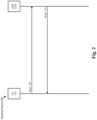
- the two-step RACH procedure comprises two particular types of messages, e.g., msgA and msgB. A general overview of the two-step RACH procedure is provided below with regard to the signaling diagram 200 of Fig. 2 .
- the four-step RACH procedure comprises four particular types of messages, e.g., msg1, msg2, msg3 and msg4.
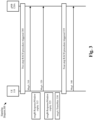
- msg1, msg2, msg3 and msg4 A general overview of the four-step RACH procedure is provided below with regard to the signaling diagram 100 of Fig. 1 .
- the UE may be configured to fallback to the four-step RACH procedure if the two-step RACH procedure is not successful.
- An example of this type of fallback scenario is provided below with regard to the signaling diagram 300 of Fig. 3 .
- the exemplary embodiments introduce techniques related to the transmission of msgl for a fallback four-step RACH procedure.
- the exemplary techniques increase the likelihood of receiving a response to the transmission of msgl and thus, increase the likelihood of a successful four-step RACH procedure.
- These exemplary techniques may be utilized in conjunction with currently implemented four-step RACH procedures, future implementations of four-step RACH procedures or independently from other four-step RACH procedures. Specific examples of each of these exemplary techniques will be provided in detail below.
- Fig. 1 shows a signaling diagram 100 for a four-step RACH procedure according to various exemplary embodiments.
- the signaling diagram 100 provides a general overview of a four-step RACH procedure and includes a UE 110 and a gNB 120A.
- the UE 110 transmits a random access preamble (e.g., msg1) to the gNB 120A.
- the random access preamble may be transmitted over the PRACH.
- the gNB 120A transmits a random access response (RAR) (e.g., msg2) to the UE 110.
- RAR random access response
- the RAR may comprise an indication that the random access preamble was successfully received and other information such as, but not limited to, resource allocation information for subsequent RACH procedure transmissions (e.g., msg3, etc.).
- the UE 110 transmits a RRC connection request (e.g., msg3) to the gNB 120A.
- a RRC connection request e.g., msg3
- the RRC connection request is one example of msg3.
- the contents and type of message that is configured as msg3 may vary depending on the relevant scenario. However, msg3 is beyond the scope of the exemplary embodiments.
- the gNB 120A transmits a contention resolution message (e.g., msg4) to the UE 110.
- a contention resolution message e.g., msg4
- the UE 110 may transmit a hybrid automatic request (HARQ) acknowledgement (ACK) in response to msg4.
- HARQ hybrid automatic request
- ACK hybrid automatic request acknowledgement
- Fig. 2 shows a signaling diagram 200 for a two-step RACH procedure according to various exemplary embodiments.
- the signaling diagram 200 provides a general overview of a two-step RACH procedure and includes the UE 110 and the gNB 120A.
- the UE 110 transmits a random access preamble and PUSCH data (e.g., msgA) to the gNB 120A.
- the random access preamble may be a PRACH transmission.
- msgA may be represented as a combination of msgl and msg3.
- the gNB 120A transmits a RAR to the UE 110 (e.g., msgB).
- msgB may be represented as a combination of msg2 and msg4.
- Fig. 3 shows a signaling diagram 300 illustrating an example scenario in which a fallback four-step RACH procedure is performed after a two-step RACH procedure fails.
- the signaling diagram 300 includes the UE 110 and the gNB 120A.
- a two-step RACH procedure is triggered.
- the UE 110 transmits msgA to the gNB 120A.
- the UE 110 may operate a timer (e.g., msgB-ResponseWindow) related to the reception of msgB in response to the transmission of msgA. If the timer expires before msgB is received, the UE 110 may be configured to retransmit msgA.
- msgB is not received in response to msgA. Accordingly, in 315, the timer expires. In 320, the UE 110 retransmits msgA to the gNB 120A. Once again, msgB is not received in response to msgA. Accordingly, in 325, the timer (e.g., msgB-ResponseWindow) expires. In the signaling diagram 300, this process of transmitting msgA and not receiving a corresponding msgB continues until the random access preamble for msgA has been transmitted a preconfigured maximum number of times (e.g., msgA-TransMax) as shown in 330.
- msgA-TransMax a preconfigured maximum number of times
- the UE 110 may be configured to fallback to the four-step RACH procedure when the two-step RACH procedure fails due to triggering msgA-TransMax.
- the UE 110 switches to the four-step RACH procedure.
- the UE 110 transmits msgl to the gNB 120A in accordance with the four-step RACH procedure.
- the four-step RACH procedure may fail and the UE 110 may attempt a RACH procedure with a different base station or the four-step RACH procedure may be performed as shown in the signaling diagram 100 of Fig. 1 .
- the exemplary embodiments introduce techniques related to the transmission of msgl in the fallback four-step RACH procedure.
- An example of this transmission is shown by 340 in the signaling diagram 300 of Fig. 3 .
- these exemplary techniques may provide benefits to the type of scenario illustrated by the signaling diagram 300, the exemplary embodiments are not limited to the scenario depicted in the signaling diagram 300.
- the exemplary embodiments may apply to any scenario in which the UE 110 performs a two-step RACH procedure on a target node and then performs a four-step RACH procedure on the same node.
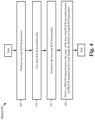
- Fig. 4 shows a method 400 for configuring a random access preamble transmission for a fallback four-step RACH procedure according to various exemplary embodiments.
- the method 400 is described from the perspective of the UE 110 and with reference to the signaling diagram 300 in Fig. 3 .
- the UE 110 performs a two-step RACH procedure.
- the two-step RACH procedure fails.
- An example of a two-step RACH procedure failure due to triggering msgA-TransMax was provided above with regard to 305-330 of the signaling diagram 300.
- the UE 110 may utilize information associated with the failed two-step RACH procedure to configure the four-step RACH procedure.
- Fig. 5 shows a signaling diagram 500 illustrating one example of performing multiple msgA transmissions during a failed two-step RACH procedure according to various exemplary embodiments.
- the UE 110 transmits msgA six times 505-530 without receive a msgB in response.
- the preconfigured maximum number of transmissions of the random access preamble for msg A e.g., msgA-TransMax
- msgA-TransMax the preconfigured maximum number of transmissions of the random access preamble for msg A
- N1-N6 measured in units of decibels (dB) is provided.
- This example is not intended to limit the exemplary embodiments in any way. Instead, this example is merely provided to illustrate that during a failed two-step RACH procedure the UE 110 may transmit msgA multiple times using a different PRACH transmit power parameter value each time.
- the UE 110 switches to a four-step RACH procedure.
- the UE 110 may be configured to fallback to the four-step RACH procedure when the parameter msgA-TransMax is triggered or in response to any other appropriate condition.
- the UE 110 derives a PRACH transmit power for msgl of the four-step RACH procedure based on PRACH transmit power used during the failed two-step RACH procedure.
- a PRACH transmit power for msgl of the four-step RACH procedure based on PRACH transmit power used during the failed two-step RACH procedure.
- Fig. 6 shows a signaling diagram 600 illustrating an example of performing multiple transmissions of msgl during the fallback four-step RACH procedure.
- the UE 110 transmits msgl six times 605-630 without receiving a msg2.
- a preconfigured maximum number of transmissions of the random access preamble for msg 1 is triggered (e.g., msg1-TransMax).
- each subsequent transmission of msgl is performed using a different higher PRACH transmit power.
- each transmission 605-630 is labeled with a value M1-M6 measured in units of (dB).
- This example is not intended to limit the exemplary embodiments in any way. Instead, this example is merely provided to illustrate that during a four-step RACH procedure the UE 110 may transmit msgl multiple times using a different PRACH transmit power each time.
- the UE 110 may be configured to perform multiple transmission using a PRACH transmit power that is less than the PRACH transmit power used for the most recently transmitted msgA (e.g., 530). Since the PRACH transmit power N1-N6 utilized for 505-530 did not result in a response from the gNB 120A, it is unlikely that using a lower PRACH transmit power parameter for msgl (e.g., M1-M6) is to result in a response from gNB 120A. In other words, the legacy approach is inefficient because the UE 110 is configured to utilize parameters for the transmission and retransmission of msgl that are unlikely to result in a response (e.g., msg2) from the base station.
- a PRACH transmit power that is less than the PRACH transmit power used for the most recently transmitted msgA (e.g., 530). Since the PRACH transmit power N1-N6 utilized for 505-530 did not result in a response from the gNB 120A, it is unlikely
- the UE 110 may derive the PRACH transmit power for msgl based on the transmission parameter values used for the failed two-step RACH procedure. For example, the UE 110 may calculate an initial random access preamble transmit power parameter for msgl based on the transmission parameters of the most recently transmitted msgA. As indicated above, msgl may be transmitted over the PRACH and thus, the transmit power for msgl and the PRACH transmit power are similar or the same. In contrast, since msgA comprises a PRACH and PUSCH component, the total transmit power for msgA is greater than the PRACH transmit power for msgA.
- the parameter P PUSCH represents the transmit power of the msgA PUSCH payload.
- This parameter may be a function of physical resource block (PRB) size, a modulation and coding scheme (MCS) and a pathloss estimate.
- PRB size, MCS and pathloss estimate may be provided by the network via RRC signaling or obtained in any other appropriate manner.
- the parameter P PRACH represents the PRACH transmit power for msgA. This parameter may be a function of various network parameters and a pathloss estimate.
- the parameter n may represent the number of msgA transmission attempts (e.g., 0, 1... msgA-TransMax) and the parameter P ramping represents a network defined power ramping or parameter.
- the UE 110 may derive the msgl transmit power using information associated with the most recently transmitted msgA.
- P PRACH may be configured by the network.
- the exemplary embodiments introduce techniques that enable the UE 110 to derive a PRACH transmit power parameter for msgl that is based on the actual performance of the two-step RACH procedure.
- n e.g., the number of transmission attempts
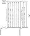
- Fig. 7 shows a signaling diagram 700 illustrating an example of deriving a PRACH transmit power parameter value for msgl of a fallback four-step RACH procedure based on the most recently transmitted msgA.
- the two-step RACH procedure is triggered.
- the UE 110 transmits msgA and in 740, the msgA-TransMax parameter is triggered. This is similar to the signaling diagram 500 of Fig. 5 .
- P MsgA P PUSCH + P PRACH + n * ( P ramping ).
- the P PUSCH may be equal to 3 dBs and the P PRACH may be equal to 1 dB.
- the P MsgA may increase for each subsequent msgA transmission attempt due to the n ⁇ ( P ramping ) .
- the UE 110 switches to the four-step RACH procedure.
- the UE 110 transmits msgl using a transmit power parameter P MSG 1 that is derived based on the most recently transmitted msgA.
- the P MSG 1 for message 750 is the value of P MsgA for transmission 735 minus the P PUSCH ⁇
- the exemplary embodiments utilize a P MSG 1 parameter value that is derived based on transmission parameters utilized for the transmission of msgA during the failed two-step RACH procedure.
- the UE 110 retransmits msg1.
- the transmission of msgl in 755 is successfully received by the gNB 120A.
- the UE gNB 120A transmits a RAR to the UE 110.
- the four-step RACH procedure may then proceed as shown in the signaling diagram 100 of Fig. 1 .
- a maximum transmit power level may be reached prior to triggering the msgA-TransMax parameter.
- the UE 110 may perform multiple transmissions of msgA using the MTPL.
- the UE 110 may fallback to the four-step RACH procedure after performing a transmission during the two-step RACH procedure using the MTPL and before the msgA-TransMax parameter is triggered.
- the UE 110 may omit or suppress one or more transmissions during the two-step RACH procedure. This may provide power saving benefits to the UE 110.
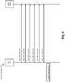
- An example of this is shown in the signaling diagram 800 of Fig. 8 .
- Fig. 8 shows a signaling diagram 800 illustrating an example of triggering the fallback four-step RACH procedure based on the MTPL.
- the signaling diagram 800 includes the UE 110 and the gNB 120A.
- the two-step RACH procedure is triggered.
- the UE 110 transmits msgA using a transmission power that is less than the MTPL.
- the UE 110 transmits msgA using the MTPL.
- the msgA-TransMax parameter has not been triggered.
- the msgA-TransMax parameter may be set to 6 but the UE 110 has only performed 4 transmissions 810-825.
- the UE 110 may transmit msgA using the MTPL until the msgA-TransMax parameter has been triggered. An example of this is shown in the signaling diagram 800 where the UE 110 performs transmissions 825a and 825b using the MTPL.
- the UE 110 triggers the fallback four-step RACH procedure after performing transmission 825 using the MTPL instead of waiting to trigger the msgA-TransMax parameter.
- transmissions 825a and 825b may be omitted or suppressed by the UE 110. This may provide the UE 110 with additional power saving benefits because the UE 110 may avoid performing transmissions that are not likely to lead to a successful RACH procedure, e.g., transmissions 825a and 825b.
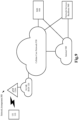
- Fig. 9 shows an exemplary network arrangement 900 according to various exemplary embodiments.
- the exemplary network arrangement 900 includes the UE 110.
- the UE 110 may be any type of electronic component that is configured to communicate via a network, e.g., mobile phones, tablet computers, desktop computers, smartphones, phablets, embedded devices, wearables, Internet of Things (IoT) devices, etc.
- IoT Internet of Things
- an actual network arrangement may include any number of UEs being used by any number of users.
- the example of a single UE 110 is merely provided for illustrative purposes.
- the UE 110 may be configured to communicate with one or more networks.
- the network with which the UE 110 may wirelessly communicate is a 5G NR radio access network (RAN) 120.
- the UE 110 may also communicate with other types of networks (e.g., 5G cloud RAN, a next generation RAN (NG-RAN), a long term evolution (LTE) RAN, a legacy cellular network, a WLAN, etc.) and the UE 110 may also communicate with networks over a wired connection.
- the UE 110 may establish a connection with the 5G NR RAN 120. Therefore, the UE 110 may have a 5G NR chipset to communicate with the 5G NR RAN 120.
- the 5G NR RAN 120 may be a portion of a cellular network that may be deployed by a network carrier (e.g., Verizon, AT&T, T-Mobile, etc.).
- the 5G NR RAN 120 may include, for example, nodes, cells or base stations (e.g., Node Bs, eNodeBs, HeNBs, eNBS, gNBs, gNodeBs, macrocells, microcells, small cells, femtocells, etc.) that are configured to send and receive traffic from UEs that are equipped with the appropriate cellular chip set.
- any association procedure may be performed for the UE 110 to connect to the 5G NR-RAN 120.
- the 5G NR-RAN 120 may be associated with a particular cellular provider where the UE 110 and/or the user thereof has a contract and credential information (e.g., stored on a SIM card).
- the UE 110 may transmit the corresponding credential information to associate with the 5G NR-RAN 120.
- the UE 110 may associate with a specific base station, e.g., e.g., the next generation Node B (gNB) 120A.
- gNB next generation Node B
- the network arrangement 900 also includes a cellular core network 930, the Internet 940, an IP Multimedia Subsystem (IMS) 950, and a network services backbone 960.
- the cellular core network 930 may be considered to be the interconnected set of components that manages the operation and traffic of the cellular network. It may include the evolved packet core (EPC) and/or the 5G core (5GC).
- the cellular core network 930 also manages the traffic that flows between the cellular network and the Internet 940.
- the IMS 950 may be generally described as an architecture for delivering multimedia services to the UE 110 using the IP protocol.
- the IMS 950 may communicate with the cellular core network 930 and the Internet 940 to provide the multimedia services to the UE 110.
- the network services backbone 960 is in communication either directly or indirectly with the Internet 940 and the cellular core network 930.
- the network services backbone 960 may be generally described as a set of components (e.g., servers, network storage arrangements, etc.) that implement a suite of services that may be used to extend the functionalities of the UE 110 in communication with the various networks.
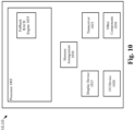
- Fig. 10 shows an exemplary UE 110 according to various exemplary embodiments.
- the UE 110 will be described with regard to the network arrangement 900 of Fig. 9 .
- the UE 110 may include a processor 1005, a memory arrangement 1010, a display device 1015, an input/output (I/O) device 1020, a transceiver 1025 and other components 1030.
- the other components 1030 may include, for example, an audio input device, an audio output device, a power supply, a data acquisition device, ports to electrically connect the UE 110 to other electronic devices, etc.
- the processor 905 may be configured to execute a plurality of engines of the UE 110.
- the engines may include a fallback RACH engine 935.
- the fallback RACH engine 935 may perform various operations related to a fallback four-step RACH procedure including, but not limited to, receiving configuration information, deriving transmit power parameters for msg1 and triggering the switch from the two-step RACH procedure to the four-step RACH procedure.
- the above referenced engine 935 being an application (e.g., a program) executed by the processor 905 is merely provided for illustrative purposes.
- the functionality associated with the engine 935 may also be represented as a separate incorporated component of the UE 110 or may be a modular component coupled to the UE 110, e.g., an integrated circuit with or without firmware.
- the integrated circuit may include input circuitry to receive signals and processing circuitry to process the signals and other information.
- the engines may also be embodied as one application or separate applications.
- the functionality described for the processor 905 is split among two or more processors such as a baseband processor and an applications processor.
- the exemplary embodiments may be implemented in any of these or other configurations of a UE.
- the memory arrangement 910 may be a hardware component configured to store data related to operations performed by the UE 110.
- the display device 915 may be a hardware component configured to show data to a user while the I/O device 1020 may be a hardware component that enables the user to enter inputs.
- the display device 1015 and the I/O device 1020 may be separate components or integrated together such as a touchscreen.
- the transceiver 1025 may be a hardware component configured to establish a connection with the 5G NR-RAN 120, an LTE-RAN (not pictured), a legacy RAN (not pictured), a WLAN (not pictured), etc. Accordingly, the transceiver 1025 may operate on a variety of different frequencies or channels (e.g., set of consecutive frequencies) .
- Fig. 11 shows an exemplary base station 1100 according to various exemplary embodiments.
- the base station 1100 may represent the gNB 120A or any other type of access node through which the UE 110 may establish a connection and manage network operations.
- the base station 1100 may include a processor 1105, a memory arrangement 1110, an input/output (I/O) device 1115, a transceiver 1120, and other components 1125.
- the other components 1125 may include, for example, an audio input device, an audio output device, a battery, a data acquisition device, ports to electrically connect the base station 1100 to other electronic devices, etc.
- the processor 1105 may be configured to execute a plurality of engines of the base station 1100.
- the engines may include a RACH engine 1130.
- the RACH engine 1130 may perform various operations related to two-step RACH and four-step RACH procedures.
- the above noted engine 1130 being an application (e.g., a program) executed by the processor 1105 is only exemplary.
- the functionality associated with the engine 1130 may also be represented as a separate incorporated component of the base station 1100 or may be a modular component coupled to the base station 1100, e.g., an integrated circuit with or without firmware.
- the integrated circuit may include input circuitry to receive signals and processing circuitry to process the signals and other information.
- the functionality described for the processor 1105 is split among a plurality of processors (e.g., a baseband processor, an applications processor, etc.).
- the exemplary embodiments may be implemented in any of these or other configurations of a base station.
- the memory 1110 may be a hardware component configured to store data related to operations performed by the base station 1100.
- the I/O device 1115 may be a hardware component or ports that enable a user to interact with the base station 1100.
- the transceiver 1120 may be a hardware component configured to exchange data with the UE 110 and any other UE in the network arrangement 900.
- the transceiver 1120 may operate on a variety of different frequencies or channels (e.g., set of consecutive frequencies). Therefore, the transceiver 1120 may include one or more components (e.g., radios) to enable the data exchange with the various networks and UEs.
- An exemplary hardware platform for implementing the exemplary embodiments may include, for example, an Intel x86 based platform with compatible operating system, a Windows OS, a Mac platform and MAC OS, a mobile device having an operating system such as iOS, Android, etc.
- the exemplary embodiments of the above described method may be embodied as a program containing lines of code stored on a non-transitory computer readable storage medium that, when compiled, may be executed on a processor or microprocessor.
- personally identifiable information should follow privacy policies and practices that are generally recognized as meeting or exceeding industry or governmental requirements for maintaining the privacy of users.
- personally identifiable information data should be managed and handled so as to minimize risks of unintentional or unauthorized access or use, and the nature of authorized use should be clearly indicated to users.
Landscapes
- Engineering & Computer Science (AREA)
- Computer Networks & Wireless Communication (AREA)
- Signal Processing (AREA)
- Mobile Radio Communication Systems (AREA)
Abstract
Description
- This application claims priority to
US Provisional Application Serial No. 63/261,596 entitled, "Efficient PRACH Transmission in a Fallback RACH Procedure," filed on September 24, 2021 - A user equipment (UE) may perform a random access channel (RACH) procedure to synchronize with a base station. In some networks, the UE may initially attempt a two-step RACH procedure. If the two-step RACH procedure is unsuccessful, the UE may fallback to a four-step RACH procedure.
- Some exemplary embodiments are related to a processor of a user equipment (UE) configured to perform operations. The operations include initiating a two-step random access channel (RACH) procedure to synchronize with a base station, initiating a fallback four-step RACH procedure after the two-step RACH procedure, configuring a random access preamble transmission for the four-step RACH procedure, wherein configuring the random access preamble transmission comprises deriving a physical random access channel (PRACH) transmit power parameter value based on a parameter used to perform a transmission during the two-step RACH procedure and transmitting the random access preamble for the four-step RACH procedure to the base station.
- Other exemplary embodiments are related to a user equipment (UE) having a transceiver configured to communicate with a base station and a processor communicatively coupled to the transceiver and configured to perform operations. The operations include initiating a two-step random access channel (RACH) procedure to synchronize with the base station, initiating a fallback four-step RACH procedure after the two-step RACH procedure, configuring a random access preamble transmission for the four-step RACH procedure, wherein configuring the random access preamble transmission comprises deriving a physical random access channel (PRACH) transmit power parameter value based on a parameter used to perform a transmission during the two-step RACH procedure and transmitting the random access preamble for the four-step RACH procedure to the base station.
- Still further exemplary embodiments are related to a method that includes initiating a two-step random access channel (RACH) procedure to synchronize with a base station, initiating a fallback four-step RACH procedure after the two-step RACH procedure, configuring a random access preamble transmission for the four-step RACH procedure, wherein configuring the random access preamble transmission comprises deriving a physical random access channel (PRACH) transmit power parameter value based on a parameter used to perform a transmission during the two-step RACH procedure and transmitting the random access preamble for the four-step RACH procedure to the base station.
-
-
Fig. 1 shows a signaling diagram for a four-step random access channel (RACH) procedure according to various exemplary embodiments. -
Fig. 2 shows a signaling diagram for a two-step RACH procedure according to various exemplary embodiments. -
Fig. 3 shows a signaling diagram illustrating an example scenario in which a fallback four-step RACH procedure is performed after a two-step RACH procedure fails according to various exemplary embodiments. -
Fig. 4 shows a method for configuring a random access preamble transmission of a fallback four-step RACH procedure according to various exemplary embodiments. -
Fig. 5 shows a signaling diagram illustrating one example of performing multiple msgA transmissions during a failed two-step RACH procedure according to various exemplary embodiments. -
Fig. 6 shows a signaling diagram illustrating an example of performing multiple transmissions of msg1 during the fallback four-step RACH procedure according to various exemplary embodiments. -
Fig. 7 shows a signaling diagram illustrating an example of deriving a PRACH transmit power parameter value for msg1 of a fallback four-step RACH procedure based on the most recently transmitted msgA according to various exemplary embodiments. -
Fig. 8 shows a signaling diagram illustrating an example of triggering the fallback four-step RACH procedure based on the maximum transmission power level (MTPL). -
Fig. 9 shows an exemplary network arrangement according to various exemplary embodiments. -
Fig. 10 shows an exemplary user equipment (UE) according to various exemplary embodiments. -
Fig. 11 shows an exemplary base station according to various exemplary embodiments. - The exemplary embodiments may be further understood with reference to the following description and the related appended drawings, wherein like elements are provided with the same reference numerals. The exemplary embodiments relate to a user equipment (UE) configured to fallback to a four-step RACH procedure when a two-step RACH procedure is unsuccessful. The exemplary embodiments introduce techniques that may reduce the latency, signaling overhead and power drain associated with a fallback four-step RACH procedure.
- The exemplary embodiments are described with regard to the UE participating in a signaling exchange with a next generation node B (gNB) of a fifth generation (5G) new radio (NR) network. The UE as described herein is used to represent any suitable electronic device that is configured with the hardware, software, and/or firmware to exchange information (e.g., control information) and/or data with a network. Further, reference to the gNB and the 5G NR network is provided as an example and is not intended to limit the exemplary embodiments in any way. The exemplary embodiments may apply to any type of base station or access node configured to participate in the fallback four-step RACH procedure and deployed within any appropriate type of network.
- The UE may perform the RACH procedure to synchronize with the gNB. To provide some examples, the UE may perform the RACH procedure for initial access or to establish a radio resource control (RRC) connected state. Those skilled in the art will understand that the terms "two-step RACH procedure" and "four-step RACH procedure" refer to third generation partnership project (3GPP) defined procedures. The two-step RACH procedure comprises two particular types of messages, e.g., msgA and msgB. A general overview of the two-step RACH procedure is provided below with regard to the signaling diagram 200 of
Fig. 2 . - The four-step RACH procedure comprises four particular types of messages, e.g., msg1, msg2, msg3 and msg4. A general overview of the four-step RACH procedure is provided below with regard to the signaling diagram 100 of
Fig. 1 . - As indicated above, the UE may be configured to fallback to the four-step RACH procedure if the two-step RACH procedure is not successful. An example of this type of fallback scenario is provided below with regard to the signaling diagram 300 of
Fig. 3 . - The exemplary embodiments introduce techniques related to the transmission of msgl for a fallback four-step RACH procedure. As will be described in more detail below, the exemplary techniques increase the likelihood of receiving a response to the transmission of msgl and thus, increase the likelihood of a successful four-step RACH procedure. These exemplary techniques may be utilized in conjunction with currently implemented four-step RACH procedures, future implementations of four-step RACH procedures or independently from other four-step RACH procedures. Specific examples of each of these exemplary techniques will be provided in detail below.
-
Fig. 1 shows a signaling diagram 100 for a four-step RACH procedure according to various exemplary embodiments. The signaling diagram 100 provides a general overview of a four-step RACH procedure and includes aUE 110 and a gNB 120A. - In 150, the UE 110 transmits a random access preamble (e.g., msg1) to the gNB 120A. The random access preamble may be transmitted over the PRACH. In 155, in response to msg1, the
gNB 120A transmits a random access response (RAR) (e.g., msg2) to theUE 110. The RAR may comprise an indication that the random access preamble was successfully received and other information such as, but not limited to, resource allocation information for subsequent RACH procedure transmissions (e.g., msg3, etc.). - In 160, the UE 110 transmits a RRC connection request (e.g., msg3) to the gNB 120A. Those skilled in the art will understand that the RRC connection request is one example of msg3. The contents and type of message that is configured as msg3 may vary depending on the relevant scenario. However, msg3 is beyond the scope of the exemplary embodiments.
- In 165, the gNB 120A transmits a contention resolution message (e.g., msg4) to the UE 110. In some embodiments, during or after the RACH procedure, the UE 110 may transmit a hybrid automatic request (HARQ) acknowledgement (ACK) in response to msg4.
-
Fig. 2 shows a signaling diagram 200 for a two-step RACH procedure according to various exemplary embodiments. The signaling diagram 200 provides a general overview of a two-step RACH procedure and includes theUE 110 and the gNB 120A. - In 205, the UE 110 transmits a random access preamble and PUSCH data (e.g., msgA) to the gNB 120A. The random access preamble may be a PRACH transmission. Generally, msgA may be represented as a combination of msgl and msg3. In 210, the gNB 120A transmits a RAR to the UE 110 (e.g., msgB). Generally, msgB may be represented as a combination of msg2 and msg4.
-
Fig. 3 shows a signaling diagram 300 illustrating an example scenario in which a fallback four-step RACH procedure is performed after a two-step RACH procedure fails. The signaling diagram 300 includes theUE 110 and thegNB 120A. - In 305, a two-step RACH procedure is triggered. In 310, the
UE 110 transmits msgA to thegNB 120A. TheUE 110 may operate a timer (e.g., msgB-ResponseWindow) related to the reception of msgB in response to the transmission of msgA. If the timer expires before msgB is received, theUE 110 may be configured to retransmit msgA. - In this example, msgB is not received in response to msgA. Accordingly, in 315, the timer expires. In 320, the
UE 110 retransmits msgA to thegNB 120A. Once again, msgB is not received in response to msgA. Accordingly, in 325, the timer (e.g., msgB-ResponseWindow) expires. In the signaling diagram 300, this process of transmitting msgA and not receiving a corresponding msgB continues until the random access preamble for msgA has been transmitted a preconfigured maximum number of times (e.g., msgA-TransMax) as shown in 330. - The
UE 110 may be configured to fallback to the four-step RACH procedure when the two-step RACH procedure fails due to triggering msgA-TransMax. In 335, theUE 110 switches to the four-step RACH procedure. In 340, theUE 110 transmits msgl to thegNB 120A in accordance with the four-step RACH procedure. Subsequently, the four-step RACH procedure may fail and theUE 110 may attempt a RACH procedure with a different base station or the four-step RACH procedure may be performed as shown in the signaling diagram 100 ofFig. 1 . - The exemplary embodiments introduce techniques related to the transmission of msgl in the fallback four-step RACH procedure. An example of this transmission is shown by 340 in the signaling diagram 300 of
Fig. 3 . However, while these exemplary techniques may provide benefits to the type of scenario illustrated by the signaling diagram 300, the exemplary embodiments are not limited to the scenario depicted in the signaling diagram 300. The exemplary embodiments may apply to any scenario in which theUE 110 performs a two-step RACH procedure on a target node and then performs a four-step RACH procedure on the same node. -
Fig. 4 shows amethod 400 for configuring a random access preamble transmission for a fallback four-step RACH procedure according to various exemplary embodiments. Themethod 400 is described from the perspective of theUE 110 and with reference to the signaling diagram 300 inFig. 3 . - In 405, the
UE 110 performs a two-step RACH procedure. In 410, the two-step RACH procedure fails. An example of a two-step RACH procedure failure due to triggering msgA-TransMax was provided above with regard to 305-330 of the signaling diagram 300. As will be described in more detail below, theUE 110 may utilize information associated with the failed two-step RACH procedure to configure the four-step RACH procedure. -
Fig. 5 shows a signaling diagram 500 illustrating one example of performing multiple msgA transmissions during a failed two-step RACH procedure according to various exemplary embodiments. In this example, theUE 110 transmits msgA six times 505-530 without receive a msgB in response. In 535, the preconfigured maximum number of transmissions of the random access preamble for msg A (e.g., msgA-TransMax) is triggered. Ion the example ofFig. 5 , it may be considered that each subsequent transmission of msgA is performed using a different higher PRACH transmit power. To demonstrate the different PRACH transmit power parameters configured for each transmission 505-530 a value N1-N6 measured in units of decibels (dB) is provided. This example is not intended to limit the exemplary embodiments in any way. Instead, this example is merely provided to illustrate that during a failed two-step RACH procedure theUE 110 may transmit msgA multiple times using a different PRACH transmit power parameter value each time. - Returning to the
method 400, in 415, theUE 110 switches to a four-step RACH procedure. TheUE 110 may be configured to fallback to the four-step RACH procedure when the parameter msgA-TransMax is triggered or in response to any other appropriate condition. - In 420, the
UE 110 derives a PRACH transmit power for msgl of the four-step RACH procedure based on PRACH transmit power used during the failed two-step RACH procedure. Prior to discussing the exemplary techniques, an example of the legacy approach is provided below with regard toFig. 6 . -
Fig. 6 shows a signaling diagram 600 illustrating an example of performing multiple transmissions of msgl during the fallback four-step RACH procedure. In this example, theUE 110 transmits msgl six times 605-630 without receiving a msg2. In 635, a preconfigured maximum number of transmissions of the random access preamble formsg 1 is triggered (e.g., msg1-TransMax). Here, each subsequent transmission of msgl is performed using a different higher PRACH transmit power. To demonstrate the different PRACH transmit power parameters each transmission 605-630 is labeled with a value M1-M6 measured in units of (dB). This example is not intended to limit the exemplary embodiments in any way. Instead, this example is merely provided to illustrate that during a four-step RACH procedure theUE 110 may transmit msgl multiple times using a different PRACH transmit power each time. - To demonstrate the legacy approach, consider a scenario in which M1-M6 of
Fig. 6 is less than N6 ofFig. 5 . Thus, under conventional circumstances, when theUE 110 switches to the four-step RACH procedure theUE 110 may be configured to perform multiple transmission using a PRACH transmit power that is less than the PRACH transmit power used for the most recently transmitted msgA (e.g., 530). Since the PRACH transmit power N1-N6 utilized for 505-530 did not result in a response from thegNB 120A, it is unlikely that using a lower PRACH transmit power parameter for msgl (e.g., M1-M6) is to result in a response fromgNB 120A. In other words, the legacy approach is inefficient because theUE 110 is configured to utilize parameters for the transmission and retransmission of msgl that are unlikely to result in a response (e.g., msg2) from the base station. - Returning to the
method 400, as mentioned above, theUE 110 may derive the PRACH transmit power for msgl based on the transmission parameter values used for the failed two-step RACH procedure. For example, theUE 110 may calculate an initial random access preamble transmit power parameter for msgl based on the transmission parameters of the most recently transmitted msgA. As indicated above, msgl may be transmitted over the PRACH and thus, the transmit power for msgl and the PRACH transmit power are similar or the same. In contrast, since msgA comprises a PRACH and PUSCH component, the total transmit power for msgA is greater than the PRACH transmit power for msgA. - MsgA transmit power may be represented by the following equation: PMsgA = PPUSCH + PPRACH + n ∗ (Pramping )
- The parameter PPUSCH represents the transmit power of the msgA PUSCH payload. This parameter may be a function of physical resource block (PRB) size, a modulation and coding scheme (MCS) and a pathloss estimate. The PRB size, MCS and pathloss estimate may be provided by the network via RRC signaling or obtained in any other appropriate manner.
- The parameter PPRACH represents the PRACH transmit power for msgA. This parameter may be a function of various network parameters and a pathloss estimate. The parameter n may represent the number of msgA transmission attempts (e.g., 0, 1... msgA-TransMax) and the parameter Pramping represents a network defined power ramping or parameter.
- The
UE 110 may derive the msgl transmit power using information associated with the most recently transmitted msgA. Msg1 transmit power may be represented by the following equation: P MSG1 = PPRACH + n ∗ (Pramping ). Under conventional circumstances, PPRACH may be configured by the network. The exemplary embodiments introduce techniques that enable theUE 110 to derive a PRACH transmit power parameter for msgl that is based on the actual performance of the two-step RACH procedure. - The
UE 110 may derive the PPRACH for the msgl transmission based on the PMsgA = PPUSCH + PPRACH + n * (Pramping ) used for the most recently transmitted msgA. For example, theUE 110 may subtract the PPUSCH of the most recently transmitted msgA from PMsgA of the most recently transmitted msgA to derive the P MSG1 for the initial transmission of msgl. For subsequent transmissions, P MSG1 may be increased by the parameter n (e.g., the number of transmission attempts). -
Fig. 7 shows a signaling diagram 700 illustrating an example of deriving a PRACH transmit power parameter value for msgl of a fallback four-step RACH procedure based on the most recently transmitted msgA. In 705, the two-step RACH procedure is triggered. In 710-735, theUE 110 transmits msgA and in 740, the msgA-TransMax parameter is triggered. This is similar to the signaling diagram 500 ofFig. 5 . - To provide an example of how the PRACH transmit power for msgl may be derived in accordance with the exemplary techniques described herein, simplified example values are shown for each transmission 710-735. These values are not intended to limit the exemplary embodiments in any way and are merely provided to demonstrate the relationship between the failed two-step RACH procedure and the fallback four-step RACH procedure.
- As mentioned above, PMsgA = PPUSCH + PPRACH + n * (Pramping ). For each transmission 710-735, the PPUSCH may be equal to 3 dBs and the PPRACH may be equal to 1 dB. The PMsgA may increase for each subsequent msgA transmission attempt due to the n ∗ (Pramping ).
- In 745, the
UE 110 switches to the four-step RACH procedure. In 750, theUE 110 transmits msgl using a transmit power parameter P MSG1 that is derived based on the most recently transmitted msgA. Thus, in this example, the P MSG1 formessage 750 is the value of PMsgA for transmission 735 minus the PPUSCH· Accordingly, instead of using a network assigned parameter for P MSG1 like in the legacy approach depicted inFig. 6 , the exemplary embodiments utilize a P MSG1 parameter value that is derived based on transmission parameters utilized for the transmission of msgA during the failed two-step RACH procedure. - In 755, the
UE 110 retransmits msg1. In this example, it is assumed that the transmission of msgl in 755 is successfully received by thegNB 120A. As a result, in 760, theUE gNB 120A transmits a RAR to theUE 110. The four-step RACH procedure may then proceed as shown in the signaling diagram 100 ofFig. 1 . - In some scenarios, during the two-step RACH procedure, a maximum transmit power level (MTPL) may be reached prior to triggering the msgA-TransMax parameter. As a result, the
UE 110 may perform multiple transmissions of msgA using the MTPL. In some embodiments, theUE 110 may fallback to the four-step RACH procedure after performing a transmission during the two-step RACH procedure using the MTPL and before the msgA-TransMax parameter is triggered. Thus, theUE 110 may omit or suppress one or more transmissions during the two-step RACH procedure. This may provide power saving benefits to theUE 110. An example of this is shown in the signaling diagram 800 ofFig. 8 . -
Fig. 8 shows a signaling diagram 800 illustrating an example of triggering the fallback four-step RACH procedure based on the MTPL. The signaling diagram 800 includes theUE 110 and thegNB 120A. - In 805, the two-step RACH procedure is triggered. In 810-820, the
UE 110 transmits msgA using a transmission power that is less than the MTPL. - In 825, the
UE 110 transmits msgA using the MTPL. At this time, the msgA-TransMax parameter has not been triggered. For instance, in this example, the msgA-TransMax parameter may be set to 6 but theUE 110 has only performed 4 transmissions 810-825. As indicated above, in some embodiments, theUE 110 may transmit msgA using the MTPL until the msgA-TransMax parameter has been triggered. An example of this is shown in the signaling diagram 800 where theUE 110 performs transmissions 825a and 825b using the MTPL. - However, in 830, the
UE 110 triggers the fallback four-step RACH procedure after performing transmission 825 using the MTPL instead of waiting to trigger the msgA-TransMax parameter. Thus, transmissions 825a and 825b may be omitted or suppressed by theUE 110. This may provide theUE 110 with additional power saving benefits because theUE 110 may avoid performing transmissions that are not likely to lead to a successful RACH procedure, e.g., transmissions 825a and 825b. -
Fig. 9 shows anexemplary network arrangement 900 according to various exemplary embodiments. Theexemplary network arrangement 900 includes theUE 110. Those skilled in the art will understand that theUE 110 may be any type of electronic component that is configured to communicate via a network, e.g., mobile phones, tablet computers, desktop computers, smartphones, phablets, embedded devices, wearables, Internet of Things (IoT) devices, etc. It should also be understood that an actual network arrangement may include any number of UEs being used by any number of users. Thus, the example of asingle UE 110 is merely provided for illustrative purposes. - The
UE 110 may be configured to communicate with one or more networks. In the example of thenetwork configuration 100, the network with which theUE 110 may wirelessly communicate is a 5G NR radio access network (RAN) 120. However, theUE 110 may also communicate with other types of networks (e.g., 5G cloud RAN, a next generation RAN (NG-RAN), a long term evolution (LTE) RAN, a legacy cellular network, a WLAN, etc.) and theUE 110 may also communicate with networks over a wired connection. With regard to the exemplary embodiments, theUE 110 may establish a connection with the5G NR RAN 120. Therefore, theUE 110 may have a 5G NR chipset to communicate with the5G NR RAN 120. - The
5G NR RAN 120 may be a portion of a cellular network that may be deployed by a network carrier (e.g., Verizon, AT&T, T-Mobile, etc.). The5G NR RAN 120 may include, for example, nodes, cells or base stations (e.g., Node Bs, eNodeBs, HeNBs, eNBS, gNBs, gNodeBs, macrocells, microcells, small cells, femtocells, etc.) that are configured to send and receive traffic from UEs that are equipped with the appropriate cellular chip set. - Those skilled in the art will understand that any association procedure may be performed for the
UE 110 to connect to the 5G NR-RAN 120. For example, as discussed above, the 5G NR-RAN 120 may be associated with a particular cellular provider where theUE 110 and/or the user thereof has a contract and credential information (e.g., stored on a SIM card). Upon detecting the presence of the 5G NR-RAN 120, theUE 110 may transmit the corresponding credential information to associate with the 5G NR-RAN 120. More specifically, theUE 110 may associate with a specific base station, e.g., e.g., the next generation Node B (gNB) 120A. - The
network arrangement 900 also includes acellular core network 930, theInternet 940, an IP Multimedia Subsystem (IMS) 950, and anetwork services backbone 960. Thecellular core network 930 may be considered to be the interconnected set of components that manages the operation and traffic of the cellular network. It may include the evolved packet core (EPC) and/or the 5G core (5GC). Thecellular core network 930 also manages the traffic that flows between the cellular network and theInternet 940. TheIMS 950 may be generally described as an architecture for delivering multimedia services to theUE 110 using the IP protocol. TheIMS 950 may communicate with thecellular core network 930 and theInternet 940 to provide the multimedia services to theUE 110. Thenetwork services backbone 960 is in communication either directly or indirectly with theInternet 940 and thecellular core network 930. Thenetwork services backbone 960 may be generally described as a set of components (e.g., servers, network storage arrangements, etc.) that implement a suite of services that may be used to extend the functionalities of theUE 110 in communication with the various networks. -
Fig. 10 shows anexemplary UE 110 according to various exemplary embodiments. TheUE 110 will be described with regard to thenetwork arrangement 900 ofFig. 9 . TheUE 110 may include aprocessor 1005, amemory arrangement 1010, adisplay device 1015, an input/output (I/O)device 1020, atransceiver 1025 andother components 1030. Theother components 1030 may include, for example, an audio input device, an audio output device, a power supply, a data acquisition device, ports to electrically connect theUE 110 to other electronic devices, etc. - The processor 905 may be configured to execute a plurality of engines of the
UE 110. For example, the engines may include a fallback RACH engine 935. The fallback RACH engine 935 may perform various operations related to a fallback four-step RACH procedure including, but not limited to, receiving configuration information, deriving transmit power parameters for msg1 and triggering the switch from the two-step RACH procedure to the four-step RACH procedure. - The above referenced engine 935 being an application (e.g., a program) executed by the processor 905 is merely provided for illustrative purposes. The functionality associated with the engine 935 may also be represented as a separate incorporated component of the
UE 110 or may be a modular component coupled to theUE 110, e.g., an integrated circuit with or without firmware. For example, the integrated circuit may include input circuitry to receive signals and processing circuitry to process the signals and other information. The engines may also be embodied as one application or separate applications. In addition, in some UEs, the functionality described for the processor 905 is split among two or more processors such as a baseband processor and an applications processor. The exemplary embodiments may be implemented in any of these or other configurations of a UE. - The memory arrangement 910 may be a hardware component configured to store data related to operations performed by the
UE 110. The display device 915 may be a hardware component configured to show data to a user while the I/O device 1020 may be a hardware component that enables the user to enter inputs. Thedisplay device 1015 and the I/O device 1020 may be separate components or integrated together such as a touchscreen. Thetransceiver 1025 may be a hardware component configured to establish a connection with the 5G NR-RAN 120, an LTE-RAN (not pictured), a legacy RAN (not pictured), a WLAN (not pictured), etc. Accordingly, thetransceiver 1025 may operate on a variety of different frequencies or channels (e.g., set of consecutive frequencies) . -
Fig. 11 shows anexemplary base station 1100 according to various exemplary embodiments. Thebase station 1100 may represent thegNB 120A or any other type of access node through which theUE 110 may establish a connection and manage network operations. - The
base station 1100 may include aprocessor 1105, amemory arrangement 1110, an input/output (I/O)device 1115, atransceiver 1120, andother components 1125. Theother components 1125 may include, for example, an audio input device, an audio output device, a battery, a data acquisition device, ports to electrically connect thebase station 1100 to other electronic devices, etc. - The
processor 1105 may be configured to execute a plurality of engines of thebase station 1100. For example, the engines may include aRACH engine 1130. TheRACH engine 1130 may perform various operations related to two-step RACH and four-step RACH procedures. - The above
noted engine 1130 being an application (e.g., a program) executed by theprocessor 1105 is only exemplary. The functionality associated with theengine 1130 may also be represented as a separate incorporated component of thebase station 1100 or may be a modular component coupled to thebase station 1100, e.g., an integrated circuit with or without firmware. For example, the integrated circuit may include input circuitry to receive signals and processing circuitry to process the signals and other information. In addition, in some base stations, the functionality described for theprocessor 1105 is split among a plurality of processors (e.g., a baseband processor, an applications processor, etc.). The exemplary embodiments may be implemented in any of these or other configurations of a base station. - The
memory 1110 may be a hardware component configured to store data related to operations performed by thebase station 1100. The I/O device 1115 may be a hardware component or ports that enable a user to interact with thebase station 1100. Thetransceiver 1120 may be a hardware component configured to exchange data with theUE 110 and any other UE in thenetwork arrangement 900. Thetransceiver 1120 may operate on a variety of different frequencies or channels (e.g., set of consecutive frequencies). Therefore, thetransceiver 1120 may include one or more components (e.g., radios) to enable the data exchange with the various networks and UEs. - Those skilled in the art will understand that the above-described exemplary embodiments may be implemented in any suitable software or hardware configuration or combination thereof. An exemplary hardware platform for implementing the exemplary embodiments may include, for example, an Intel x86 based platform with compatible operating system, a Windows OS, a Mac platform and MAC OS, a mobile device having an operating system such as iOS, Android, etc. The exemplary embodiments of the above described method may be embodied as a program containing lines of code stored on a non-transitory computer readable storage medium that, when compiled, may be executed on a processor or microprocessor.
- Although this application described various embodiments each having different features in various combinations, those skilled in the art will understand that any of the features of one embodiment may be combined with the features of the other embodiments in any manner not specifically disclaimed or which is not functionally or logically inconsistent with the operation of the device or the stated functions of the disclosed embodiments.
- It is well understood that the use of personally identifiable information should follow privacy policies and practices that are generally recognized as meeting or exceeding industry or governmental requirements for maintaining the privacy of users. In particular, personally identifiable information data should be managed and handled so as to minimize risks of unintentional or unauthorized access or use, and the nature of authorized use should be clearly indicated to users.
- It will be apparent to those skilled in the art that various modifications may be made in the present disclosure, without departing from the spirit or the scope of the disclosure. Thus, it is intended that the present disclosure cover modifications and variations of this disclosure provided they come within the scope of the appended claims and their equivalent.
Claims (12)
- A processor of a user equipment (UE) configured to perform operations comprising:initiating a two-step random access channel (RACH) procedure to synchronize with a base station;initiating a fallback four-step RACH procedure after the two-step RACH procedure;configuring a random access preamble transmission for the four-step RACH procedure, wherein configuring the random access preamble transmission comprises deriving a physical random access channel (PRACH) transmit power parameter value based on a parameter used to perform a transmission during the two-step RACH procedure; andtransmitting the random access preamble for the four-step RACH procedure to the base station.
- The processor of claim 1, wherein the parameter used to perform the transmission during the two-step RACH procedure is a transmit power parameter corresponding to a message comprising a PRACH component and a physical uplink shared channel component (PUSCH) (msgA).
- The processor of claim 1, wherein the transmission during the two-step RACH procedure is a most recently transmitted msgA.
- The processor of claim 3, wherein deriving the PRACH transmit power parameter comprises subtracting a physical uplink shared channel (PUSCH) payload transmit power parameter value from a total transmit power parameter value corresponding to the most recently transmitted msgA.
- The processor of claim 1, wherein initiating the fallback four-step RACH procedure is triggered based on utilizing a maximum transmit power level (MTPL) during the two-step RACH procedure and wherein the fallback four-step RACH procedure occurs before a maximum number of transmissions has been performed by the UR during the two-step RACH procedure.
- The processor of claim 1, wherein the UE suppresses one or more configured transmissions during the two-step RACH procedure.
- A method, comprising:initiating a two-step random access channel (RACH) procedure to synchronize with a base station;initiating a fallback four-step RACH procedure after the two-step RACH procedure;configuring a random access preamble transmission for the four-step RACH procedure, wherein configuring the random access preamble transmission comprises deriving a physical random access channel (PRACH) transmit power parameter value based on a parameter used to perform a transmission during the two-step RACH procedure; andtransmitting the random access preamble for the four-step RACH procedure to the base station.
- The method of claim 7, wherein the parameter used to perform the transmission during the two-step RACH procedure is a transmit power parameter corresponding to a message comprising a PRACH component and a physical uplink shared channel component (PUSCH) (msgA).
- The method of claim 7, wherein the transmission during the two-step RACH procedure is a most recently transmitted msgA.
- The method of claim 9, wherein deriving the PRACH transmit power parameter comprises subtracting a physical uplink shared channel (PUSCH) payload transmit power parameter value from a total transmit power parameter value corresponding to the most recently transmitted msgA.
- The method of claim 7, wherein initiating the fallback four-step RACH procedure is triggered based on utilizing a maximum transmit power level (MTPL) during the two-step RACH procedure and wherein the fallback four-step RACH procedure occurs before a maximum number of transmissions has been performed by the UR during the two-step RACH procedure.
- The method of claim 7, wherein the UE suppresses one or more configured transmissions during the two-step RACH procedure.
Applications Claiming Priority (2)
| Application Number | Priority Date | Filing Date | Title |
|---|---|---|---|
| US202163261596P | 2021-09-24 | 2021-09-24 | |
| US17/822,952 US12452807B2 (en) | 2021-09-24 | 2022-08-29 | Efficient PRACH transmission in a fallback RACH procedure |
Publications (2)
| Publication Number | Publication Date |
|---|---|
| EP4156803A1 true EP4156803A1 (en) | 2023-03-29 |
| EP4156803B1 EP4156803B1 (en) | 2026-01-21 |
Family
ID=83151712
Family Applications (1)
| Application Number | Title | Priority Date | Filing Date |
|---|---|---|---|
| EP22193193.4A Active EP4156803B1 (en) | 2021-09-24 | 2022-08-31 | Efficient prach transmission in a fallback rach procedure |
Country Status (3)
| Country | Link |
|---|---|
| US (1) | US12452807B2 (en) |
| EP (1) | EP4156803B1 (en) |
| CN (1) | CN115996478B (en) |
Citations (2)
| Publication number | Priority date | Publication date | Assignee | Title |
|---|---|---|---|---|
| CN111527788A (en) * | 2019-04-04 | 2020-08-11 | Oppo广东移动通信有限公司 | User equipment of RACH procedure and method thereof |
| CA3132267A1 (en) * | 2019-03-28 | 2020-10-01 | Ntt Docomo, Inc. | User equipment and communication method |
Family Cites Families (3)
| Publication number | Priority date | Publication date | Assignee | Title |
|---|---|---|---|---|
| CN108271275B (en) | 2017-01-04 | 2021-02-05 | 电信科学技术研究院 | Method and device for competing random access |
| WO2021046792A1 (en) | 2019-09-12 | 2021-03-18 | Oppo广东移动通信有限公司 | Random access method and apparatus |
| US12245295B2 (en) * | 2019-10-04 | 2025-03-04 | Lenovo (Singapore) Pte. Ltd. | Method and apparatus for a two-step random access procedure |
-
2022
- 2022-08-29 US US17/822,952 patent/US12452807B2/en active Active
- 2022-08-31 EP EP22193193.4A patent/EP4156803B1/en active Active
- 2022-09-15 CN CN202211122763.4A patent/CN115996478B/en active Active
Patent Citations (3)
| Publication number | Priority date | Publication date | Assignee | Title |
|---|---|---|---|---|
| CA3132267A1 (en) * | 2019-03-28 | 2020-10-01 | Ntt Docomo, Inc. | User equipment and communication method |
| CN111527788A (en) * | 2019-04-04 | 2020-08-11 | Oppo广东移动通信有限公司 | User equipment of RACH procedure and method thereof |
| US20220030640A1 (en) * | 2019-04-04 | 2022-01-27 | Guangdong Oppo Mobile Telecommunications Corp., Ltd. | User equipment and method for a random access channel procedure of same |
Also Published As
| Publication number | Publication date |
|---|---|
| CN115996478B (en) | 2026-06-05 |
| CN115996478A (en) | 2023-04-21 |
| US12452807B2 (en) | 2025-10-21 |
| US20230099913A1 (en) | 2023-03-30 |
| EP4156803B1 (en) | 2026-01-21 |
Similar Documents
| Publication | Publication Date | Title |
|---|---|---|
| US20240188089A1 (en) | Fast Secondary Cell Activation with Temporary Reference Signals | |
| EP4133696B1 (en) | Low-layer based mobility management | |
| EP4651614A1 (en) | Wireless communication method and apparatus | |
| US11632819B2 (en) | TCI change enhancement | |
| US12328609B2 (en) | Beam information reporting for PUCCH secondary cell activation | |
| WO2023168674A1 (en) | Maintenance of multiple ta in the same serving cell for multi-trp operation | |
| JP7182002B2 (en) | Random access method and apparatus | |
| WO2020206643A1 (en) | Random access method, device, and storage medium | |
| US12439472B2 (en) | Receiving data without monitoring control channel | |
| US12284670B2 (en) | Reporting uplink listen-before-talk failure | |
| US12452807B2 (en) | Efficient PRACH transmission in a fallback RACH procedure | |
| WO2026030991A1 (en) | Rach framework with nes and sbfd rach enhancement | |
| US12317283B2 (en) | Scheduling of control signaling on a primary cell by a secondary cell | |
| US20240275541A1 (en) | Signaling-less Data Transfer | |
| EP4132176B1 (en) | Scheduling of control signaling on a primary cell by a secondary cell | |
| US12058701B2 (en) | Scheduling of control signaling on a primary cell by a secondary cell | |
| WO2023044776A1 (en) | Enhancements to support trp specific beam failure recovery |
Legal Events
| Date | Code | Title | Description |
|---|---|---|---|
| PUAI | Public reference made under article 153(3) epc to a published international application that has entered the european phase |
Free format text: ORIGINAL CODE: 0009012 |
|
| STAA | Information on the status of an ep patent application or granted ep patent |
Free format text: STATUS: REQUEST FOR EXAMINATION WAS MADE |
|
| 17P | Request for examination filed |
Effective date: 20220831 |
|
| AK | Designated contracting states |
Kind code of ref document: A1 Designated state(s): AL AT BE BG CH CY CZ DE DK EE ES FI FR GB GR HR HU IE IS IT LI LT LU LV MC MK MT NL NO PL PT RO RS SE SI SK SM TR |
|
| STAA | Information on the status of an ep patent application or granted ep patent |
Free format text: STATUS: EXAMINATION IS IN PROGRESS |
|
| 17Q | First examination report despatched |
Effective date: 20240805 |
|
| GRAP | Despatch of communication of intention to grant a patent |
Free format text: ORIGINAL CODE: EPIDOSNIGR1 |
|
| STAA | Information on the status of an ep patent application or granted ep patent |
Free format text: STATUS: GRANT OF PATENT IS INTENDED |
|
| INTG | Intention to grant announced |
Effective date: 20250804 |
|
| GRAS | Grant fee paid |
Free format text: ORIGINAL CODE: EPIDOSNIGR3 |
|
| GRAA | (expected) grant |
Free format text: ORIGINAL CODE: 0009210 |
|
| STAA | Information on the status of an ep patent application or granted ep patent |
Free format text: STATUS: THE PATENT HAS BEEN GRANTED |
|
| AK | Designated contracting states |
Kind code of ref document: B1 Designated state(s): AL AT BE BG CH CY CZ DE DK EE ES FI FR GB GR HR HU IE IS IT LI LT LU LV MC MK MT NL NO PL PT RO RS SE SI SK SM TR |
|
| REG | Reference to a national code |
Ref country code: CH Ref legal event code: F10 Free format text: ST27 STATUS EVENT CODE: U-0-0-F10-F00 (AS PROVIDED BY THE NATIONAL OFFICE) Effective date: 20260121 |
|
| REG | Reference to a national code |
Ref country code: DE Ref legal event code: R096 Ref document number: 602022028755 Country of ref document: DE |
|
| REG | Reference to a national code |
Ref country code: IE Ref legal event code: FG4D |
|
| REG | Reference to a national code |
Ref country code: NL Ref legal event code: MP Effective date: 20260121 |
|
| PG25 | Lapsed in a contracting state [announced via postgrant information from national office to epo] |
Ref country code: NL Free format text: LAPSE BECAUSE OF FAILURE TO SUBMIT A TRANSLATION OF THE DESCRIPTION OR TO PAY THE FEE WITHIN THE PRESCRIBED TIME-LIMIT Effective date: 20260121 |
|
| REG | Reference to a national code |
Ref country code: AT Ref legal event code: MK05 Ref document number: 1879733 Country of ref document: AT Kind code of ref document: T Effective date: 20260121 |
|
| PG25 | Lapsed in a contracting state [announced via postgrant information from national office to epo] |
Ref country code: RS Free format text: LAPSE BECAUSE OF FAILURE TO SUBMIT A TRANSLATION OF THE DESCRIPTION OR TO PAY THE FEE WITHIN THE PRESCRIBED TIME-LIMIT Effective date: 20260421 |
|
| PG25 | Lapsed in a contracting state [announced via postgrant information from national office to epo] |
Ref country code: ES Free format text: LAPSE BECAUSE OF FAILURE TO SUBMIT A TRANSLATION OF THE DESCRIPTION OR TO PAY THE FEE WITHIN THE PRESCRIBED TIME-LIMIT Effective date: 20260121 |
|
| PG25 | Lapsed in a contracting state [announced via postgrant information from national office to epo] |
Ref country code: PL Free format text: LAPSE BECAUSE OF FAILURE TO SUBMIT A TRANSLATION OF THE DESCRIPTION OR TO PAY THE FEE WITHIN THE PRESCRIBED TIME-LIMIT Effective date: 20260121 |
|
| PG25 | Lapsed in a contracting state [announced via postgrant information from national office to epo] |
Ref country code: GR Free format text: LAPSE BECAUSE OF FAILURE TO SUBMIT A TRANSLATION OF THE DESCRIPTION OR TO PAY THE FEE WITHIN THE PRESCRIBED TIME-LIMIT Effective date: 20260422 |
|
| REG | Reference to a national code |
Ref country code: LT Ref legal event code: MG9D |
|
| PG25 | Lapsed in a contracting state [announced via postgrant information from national office to epo] |
Ref country code: LT Free format text: LAPSE BECAUSE OF FAILURE TO SUBMIT A TRANSLATION OF THE DESCRIPTION OR TO PAY THE FEE WITHIN THE PRESCRIBED TIME-LIMIT Effective date: 20260121 |
|
| PG25 | Lapsed in a contracting state [announced via postgrant information from national office to epo] |
Ref country code: NO Free format text: LAPSE BECAUSE OF FAILURE TO SUBMIT A TRANSLATION OF THE DESCRIPTION OR TO PAY THE FEE WITHIN THE PRESCRIBED TIME-LIMIT Effective date: 20260421 |
|
| PG25 | Lapsed in a contracting state [announced via postgrant information from national office to epo] |
Ref country code: SE Free format text: LAPSE BECAUSE OF FAILURE TO SUBMIT A TRANSLATION OF THE DESCRIPTION OR TO PAY THE FEE WITHIN THE PRESCRIBED TIME-LIMIT Effective date: 20260121 Ref country code: FI Free format text: LAPSE BECAUSE OF FAILURE TO SUBMIT A TRANSLATION OF THE DESCRIPTION OR TO PAY THE FEE WITHIN THE PRESCRIBED TIME-LIMIT Effective date: 20260121 Ref country code: AT Free format text: LAPSE BECAUSE OF FAILURE TO SUBMIT A TRANSLATION OF THE DESCRIPTION OR TO PAY THE FEE WITHIN THE PRESCRIBED TIME-LIMIT Effective date: 20260121 |
|
| PG25 | Lapsed in a contracting state [announced via postgrant information from national office to epo] |
Ref country code: HR Free format text: LAPSE BECAUSE OF FAILURE TO SUBMIT A TRANSLATION OF THE DESCRIPTION OR TO PAY THE FEE WITHIN THE PRESCRIBED TIME-LIMIT Effective date: 20260121 |
|
| PG25 | Lapsed in a contracting state [announced via postgrant information from national office to epo] |
Ref country code: PT Free format text: LAPSE BECAUSE OF FAILURE TO SUBMIT A TRANSLATION OF THE DESCRIPTION OR TO PAY THE FEE WITHIN THE PRESCRIBED TIME-LIMIT Effective date: 20260521 Ref country code: IS Free format text: LAPSE BECAUSE OF FAILURE TO SUBMIT A TRANSLATION OF THE DESCRIPTION OR TO PAY THE FEE WITHIN THE PRESCRIBED TIME-LIMIT Effective date: 20260521 |
|
| PG25 | Lapsed in a contracting state [announced via postgrant information from national office to epo] |
Ref country code: LV Free format text: LAPSE BECAUSE OF FAILURE TO SUBMIT A TRANSLATION OF THE DESCRIPTION OR TO PAY THE FEE WITHIN THE PRESCRIBED TIME-LIMIT Effective date: 20260121 |
|
| PG25 | Lapsed in a contracting state [announced via postgrant information from national office to epo] |
Ref country code: BG Free format text: LAPSE BECAUSE OF FAILURE TO SUBMIT A TRANSLATION OF THE DESCRIPTION OR TO PAY THE FEE WITHIN THE PRESCRIBED TIME-LIMIT Effective date: 20260121 |