EP4156786A1 - Method for source core network node, source core network node, and non-transitory computer-readable medium - Google Patents
Method for source core network node, source core network node, and non-transitory computer-readable medium Download PDFInfo
- Publication number
- EP4156786A1 EP4156786A1 EP22755833.5A EP22755833A EP4156786A1 EP 4156786 A1 EP4156786 A1 EP 4156786A1 EP 22755833 A EP22755833 A EP 22755833A EP 4156786 A1 EP4156786 A1 EP 4156786A1
- Authority
- EP
- European Patent Office
- Prior art keywords
- message
- core network
- network node
- resource
- handover
- Prior art date
- Legal status (The legal status is an assumption and is not a legal conclusion. Google has not performed a legal analysis and makes no representation as to the accuracy of the status listed.)
- Pending
Links
Images







Classifications
-
- H—ELECTRICITY
- H04—ELECTRIC COMMUNICATION TECHNIQUE
- H04W—WIRELESS COMMUNICATION NETWORKS
- H04W36/00—Hand-off or reselection arrangements
- H04W36/0005—Control or signalling for completing the hand-off
- H04W36/0011—Control or signalling for completing the hand-off for data sessions of end-to-end connection
- H04W36/0033—Control or signalling for completing the hand-off for data sessions of end-to-end connection with transfer of context information
- H04W36/0038—Control or signalling for completing the hand-off for data sessions of end-to-end connection with transfer of context information of security context information
-
- H—ELECTRICITY
- H04—ELECTRIC COMMUNICATION TECHNIQUE
- H04L—TRANSMISSION OF DIGITAL INFORMATION, e.g. TELEGRAPHIC COMMUNICATION
- H04L5/00—Arrangements affording multiple use of the transmission path
- H04L5/003—Arrangements for allocating sub-channels of the transmission path
- H04L5/0053—Allocation of signalling, i.e. of overhead other than pilot signals
- H04L5/0055—Physical resource allocation for ACK/NACK
-
- H—ELECTRICITY
- H04—ELECTRIC COMMUNICATION TECHNIQUE
- H04W—WIRELESS COMMUNICATION NETWORKS
- H04W36/00—Hand-off or reselection arrangements
- H04W36/14—Reselecting a network or an air interface
- H04W36/144—Reselecting a network or an air interface over a different radio air interface technology
-
- H—ELECTRICITY
- H04—ELECTRIC COMMUNICATION TECHNIQUE
- H04W—WIRELESS COMMUNICATION NETWORKS
- H04W76/00—Connection management
- H04W76/20—Manipulation of established connections
- H04W76/25—Maintenance of established connections
Definitions
- the present disclosure relates to a method for a source core network node and the source core network node.
- a fifth-generation (5G) network In a telecommunications field, an effort of achieving a new generation network called a fifth-generation (5G) network has been made.
- 5G fifth-generation
- activities have been started in a plurality of research and standardization organizations.
- 3GPP third-generation partnership project
- 3GPP has been examining a next-generation communication technique and a system architecture for the 5G network being a next-generation mobile communication system.
- a 5G system (5GS) has been specified as a system for achieving the 5G mobile communication system. Specifications of the 5GS are disclosed in, for example, Non Patent Literature 1 and Non Patent Literature 2.
- a concept of "flow” is adopted as a method for transmitting user data in the 5GS.
- EPS evolved packet system
- a transmission node and a reception node each manage a tunnel for the user data transmission, and control quality of service (QoS), however, in flow control, a QoS flow identifier (QFI) is set for a header of packet data that transmits user data, and control of the QoS is performed in a flow unit.
- QFI QoS flow identifier
- Service succession with an EPS is stipulated in the 5GS.
- This is a technique for successively providing a service even when user equipment (UE) moves from a 4G to a 5G or from the 5G to the 4G since it is assumed that the 5G is introduced from an urban area in a spot manner in contrast to the 4G that covers a wide area.
- This technique is provided by an interworking procedure.
- the interworking procedure includes 5GS to EPS handover, EPS to 5GS handover, and the like.
- a flow in the 5GS there is a difference in header information of a GPRS tunneling protocol for user plane (GTP-U) being a protocol for performing user data transmission.
- GTP-U GPRS tunneling protocol for user plane
- a QFI is set for a GTP-U header being used in the 5GS, but the QFI is not set in the EPS.
- the present disclosure provides a method of appropriately managing a resource for user data control.
- a method for a source core network node includes: receiving, from a source radio access network (RAN) associated with a 5G system (5GS), a first message for canceling handover of a terminal from the 5GS to an evolved packet system (EPS); transmitting a second message to a target core network node associated with the EPS when receiving the first message; receiving a third message from the target core network node when transmitting the second message; transmitting a fourth message to the source RAN when receiving the third message; and transmitting a fifth message for releasing a resource being secured in a core network device when transmitting the fourth message.
- RAN source radio access network
- EPS evolved packet system
- a source core network node includes: a reception means for receiving, from a source radio access network (RAN) associated with a 5G system (5GS), a first message for canceling handover of a terminal from the 5GS to an evolved packet system (EPS); and a transmission means for transmitting a second message to a target core network node associated with the EPS when receiving the first message, wherein the reception means receives a third message from the target core network node when transmitting the second message, the transmission means transmits a fourth message to the source RAN when receiving the third message, and the transmission means transmits a fifth message for releasing a resource being secured in a core network device when transmitting the fourth message.
- RAN radio access network
- EPS evolved packet system
- the present disclosure is able to provide a method of appropriately managing a resource for user data control.
- a procedure of UE performing Handover from a new radio (NR) being a wireless access technique of a 5G to long term evolution (LTE) or LTE-Advanced being a wireless access technique of a 4G an operation in which the UE returns to the 5G (NR) in the middle of the Handover processing is stipulated as a Handover Cancel procedure in Non Patent Literature 2.
- NR new radio
- LTE long term evolution
- LTE-Advanced being a wireless access technique of a 4G
- a procedure of performing Handover from the NR to LTE or LTE-Advanced may be referred to as a Handover procedure from a 5GS to an EPS.
- a procedure of performing Handover from the NR to LTE or LTE-Advanced may be referred to as Handover of a terminal from the 5GS to the EPS.
- the resource for the user data control described above needs to be released, but the release of the resource is not mentioned at all in the Handover Cancel procedure described in Non Patent Literature 2.
- the resource for the user data control described above is still secured after the Handover Cancel procedure described in Non Patent Literature 2 is completed. There is a risk that such an unnecessarily secured resource hinders a cellular network.
- the present disclosure indicates a technique for appropriately releasing a resource for user data control being set by the Handover procedure from the 5GS to the EPS in the Handover Cancel procedure for the Handover procedure.
- Figs. 1 and 2 illustrate a configuration example of a cellular network according to the present disclosure.
- Each element illustrated in Figs. 1 and 2 is a network function, and provides an interface defined by a 3rd generation partnership project (3GPP).
- 3GPP 3rd generation partnership project
- each element (network function) illustrated in Figs. 1 and 2 can be implemented as a network element on dedicated hardware, as a software instance running on the dedicated hardware, or as a virtualized function being instantiated on an application platform.
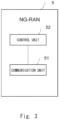
- Fig. 3 illustrates a configuration example of a next generation radio access network (NG-RAN) 5.
- the NG-RAN 5 may be referred to as an NG-RAN node, for example.
- the NG-RAN 5 may be referred to as a source radio access network (RAN) associated with a 5GS.
- the NG-RAN 5 includes a communication unit 51 and a control unit 52.
- the communication unit 51 and the control unit 52 may be software or a module whose processing is performed by a processor executing a program stored in a memory.
- the communication unit 51 and the control unit 52 may be a circuit or hardware such as a chip.
- the communication unit 51 is a functional unit for the NG-RAN 5 to be connected to a core network device included in an access network and a core network.
- the NG-RAN 5 can transmit and receive user data and/or control information to and from the core network device included in the access network and/or the core network via the communication unit 51.
- the core network device may be referred to as a core network node.
- the control unit 52 is a functional unit for controlling the NG-RAN 5, and achieves various types of processing of the entire NG-RAN 5 by reading and executing various types of information and programs being stored in a memory.
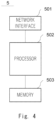
- Fig. 4 is a block diagram illustrating the configuration example of the NG-RAN 5.
- the NG-RAN 5 includes a network interface 501, a processor 502, and a memory 503.
- the network interface 501 is used for communicating with another network node device constituting a communication system.
- the network interface 501 may include, for example, a network interface card (NIC) conforming to IEEE 802.3 series.
- NIC network interface card
- the processor 502 performs processing of the NG-RAN 5 described by using a sequence diagram in the aspects described below by reading software (computer program) from the memory 503 and executing the software.
- the processor 502 may be, for example, a microprocessor, a micro processing unit (MPU), or a central processing unit (CPU).
- the processor 502 may include a plurality of processors.
- the memory 503 is formed of a combination of a volatile memory and a non-volatile memory.
- the memory 503 may include a storage disposed away from the processor 502. In this case, the processor 502 may access the memory 503 via an I/O interface that is not illustrated.
- the memory 503 is used for storing a software module group.
- the processor 502 can perform the processing of the NG-RAN 5 described in the aspects described below by reading the software module group from the memory 503 and executing the software module group.
- each processor included in the NG-RAN 5 executes one or a plurality of programs including a command group for causing a computer to perform an algorithm described by using the drawings.
- Fig. 5 illustrates a configuration example of an access and mobility management function 10.
- the AMF 10 may be referred to as an AMF device.
- the AMF 10 may be referred to as a core network node associated with the 5GS.
- the AMF 10 includes a communication unit 11 and a control unit 12.
- the communication unit 11 and the control unit 12 may be software or a module whose processing is performed by a processor executing a program stored in a memory.
- the communication unit 11 and the control unit 12 may be a circuit or hardware such as a chip.
- the communication unit 11 is a functional unit for the AMF 10 to be connected to a core network device included in an access network and a core network.
- the AMF 10 can transmit and receive user data and/or control information to and from the core network device included in the access network and/or the core network via the communication unit 11.
- the control unit 12 is a functional unit for controlling the AMF 10, and achieves various types of processing of the entire AMF 10 by reading and executing various types of information and programs being stored in a memory.
- Fig. 6 is a block diagram illustrating the configuration example of the AMF 10.
- the AMF 10 includes a network interface 1001, a processor 1002, and a memory 1003.
- the network interface 1001 is used for communicating with another network node device constituting a communication system.
- the network interface 1001 may include, for example, a network interface card (NIC) conforming to IEEE 802.3 series.
- NIC network interface card
- the processor 1002 performs processing of the AMF 10 described by using a sequence diagram in the aspects described below by reading software (computer program) from the memory 1003 and executing the software.
- the processor 1002 may be, for example, a microprocessor, a micro processing unit (MPU), or a central processing unit (CPU).
- the processor 1002 may include a plurality of processors.
- the memory 1003 is formed of a combination of a volatile memory and a non-volatile memory.
- the memory 1003 may include a storage disposed away from the processor 1002.
- the processor 1002 may access the memory 1003 via an I/O interface that is not illustrated.
- the memory 1003 is used for storing a software module group.
- the processor 1002 can perform the processing of the AMF 10 described in the aspects described below by reading the software module group from the memory 1003 and executing the software module group.
- each processor included in the AMF 10 executes one or a plurality of programs including a command group for causing a computer to perform an algorithm described by using the drawings.
- Fig. 7 illustrates a configuration example of a mobile management entity (MME) 20.
- the MME 20 may be referred to as an MME device.
- the MME 20 may be referred to as a core network node associated with the EPS.
- the MME 20 includes a communication unit 21 and a control unit 22.
- the communication unit 21 and the control unit 22 may be software or a module whose processing is performed by a processor executing a program stored in a memory.
- the communication unit 21 and the control unit 22 may be a circuit or hardware such as a chip.
- the communication unit 21 is a functional unit for the MME 20 to be connected to a core network device included in an access network and a core network.
- the MME 20 can transmit and receive user data and/or control information to and from the core network device included in the core network via the communication unit 21.
- the control unit 22 is a functional unit for controlling the MME 20, and achieves various types of processing of the entire MME 20 by reading and executing various types of information and programs being stored in a memory.
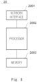
- Fig. 8 is a block diagram illustrating the configuration example of the MME 20.
- the MME 20 includes a network interface 2001, a processor 2002, and a memory 2003.
- the network interface 2001 is used for communicating with another network node device constituting a communication system.
- the network interface 2001 may include, for example, a network interface card (NIC) conforming to IEEE 802.3 series.
- NIC network interface card
- the processor 2002 performs processing of the MME 20 described by using a sequence diagram in the aspects described below by reading software (computer program) from the memory 2003 and executing the software.
- the processor 2002 may be, for example, a microprocessor, a micro processing unit (MPU), or a central processing unit (CPU).
- the processor 2002 may include a plurality of processors.
- the memory 2003 is formed of a combination of a volatile memory and a non-volatile memory.
- the memory 2003 may include a storage disposed away from the processor 2002.
- the processor 2002 may access the memory 2003 via an I/O interface that is not illustrated.
- the memory 2003 is used for storing a software module group.
- the processor 2002 can perform the processing of the MME 20 described in the aspects described below by reading the software module group from the memory 2003 and executing the software module group.
- each processor included in the MME 20 executes one or a plurality of programs including a command group for causing a computer to perform an algorithm described by using the drawings.
- Fig. 9 illustrates a configuration example of a user plane function + packet data network gateway-U (UPF+PGW-U) 30.
- the UPF+PGW-U 30 may be referred to as a UPF+PGW-U device.
- the UPF+PGW-U 30 may be referred to as a user plane device or a core network device.
- the UPF+PGW-U 30 includes a communication unit 31 and a control unit 32.
- the communication unit 31 and the control unit 32 may be software or a module whose processing is performed by a processor executing a program stored in a memory.
- the communication unit 31 and the control unit 32 may be a circuit or hardware such as a chip.
- the communication unit 31 is a functional unit for the UPF+PGW-U 30 to be connected to a core network device included in an access network and a core network.
- the UPF+PGW-U 30 can transmit and receive user data and/or control information to and from the core network device included in the core network via the communication unit 31.
- the control unit 32 is a functional unit for controlling the UPF+PGW-U 30, and achieves various types of processing of the entire UPF+PGW-U 30 by reading and executing various types of information and programs being stored in a memory.
- Fig. 10 is a block diagram illustrating the configuration example of the UPF+PGW-U 30.
- the UPF+PGW-U 30 includes a network interface 3001, a processor 3002, and a memory 3003.
- the network interface 3001 is used for communicating with another network node device constituting a communication system.
- the network interface 3001 may include, for example, a network interface card (NIC) conforming to IEEE 802.3 series.
- NIC network interface card
- the processor 3002 performs processing of the UPF+PGW-U 30 described by using a sequence diagram in the aspects described below by reading software (computer program) from the memory 3003 and executing the software.
- the processor 3002 may be, for example, a microprocessor, a micro processing unit (MPU), or a central processing unit (CPU).
- the processor 3002 may include a plurality of processors.
- the memory 3003 is formed of a combination of a volatile memory and a non-volatile memory.
- the memory 3003 may include a storage disposed away from the processor 3002.
- the processor 3002 may access the memory 3003 via an I/O interface that is not illustrated.
- the memory 3003 is used for storing a software module group.
- the processor 3002 can perform the processing of the UPF+PGW-U 30 described in the aspects described below by reading the software module group from the memory 3003 and executing the software module group.
- each processor included in the UPF+PGW-U 30 executes one or a plurality of programs including a command group for causing a computer to perform an algorithm described by using the drawings.
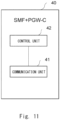
- Fig. 11 illustrates a configuration example of a session management function + packet data network gateway-C (SMF+PGW-C) 40.
- the SMF+PGW-C 40 may be referred to as a SMF+PGW-C device.
- the SMF+PGW-C 40 may be referred to as a core network device.
- the SMF+PGW-C 40 includes a communication unit 41 and a control unit 42.
- the communication unit 41 and the control unit 42 may be software or a module whose processing is performed by a processor executing a program stored in a memory.
- the communication unit 41 and the control unit 42 may be a circuit or hardware such as a chip.
- the communication unit 41 is a functional unit for the SMF+PGW-C 40 to be connected to a core network device included in an access network and a core network.
- the SMF+PGW-C 40 can transmit and receive user data and/or control information to and from the core network device included in the core network via the communication unit 41.
- the control unit 42 is a functional unit for controlling the SMF+PGW-C 40, and achieves various types of processing of the entire SMF+PGW-C 40 by reading and executing various types of information and programs being stored in a memory.
- Fig. 12 is a block diagram illustrating the configuration example of the SMF+PGW-C 40.
- the SMF+PGW-C 40 includes a network interface 4001, a processor 4002, and a memory 4003.
- the network interface 4001 is used for communicating with another network node device constituting a communication system.
- the network interface 4001 may include, for example, a network interface card (NIC) conforming to IEEE 802.3 series.
- NIC network interface card
- the processor 4002 performs processing of the SMF+PGW-C 40 described by using a sequence diagram in the aspects described below by reading software (computer program) from the memory 4003 and executing the software.
- the processor 4002 may be, for example, a microprocessor, a micro processing unit (MPU), or a central processing unit (CPU).
- the processor 4002 may include a plurality of processors.
- the memory 4003 is formed of a combination of a volatile memory and a non-volatile memory.
- the memory 4003 may include a storage disposed away from the processor 4002. In this case, the processor 4002 may access the memory 4003 via an I/O interface that is not illustrated.
- the memory 4003 is used for storing a software module group.
- the processor 4002 can perform the processing of the SMF+PGW-C 40 described in the aspects described below by reading the software module group from the memory 4003 and executing the software module group.
- each processor included in the SMF+PGW-C 40 executes one or a plurality of programs including a command group for causing a computer to perform an algorithm described by using the drawings.
- Fig. 13 illustrates a configuration example of a serving gateway control plane function (SGW-C) 60.
- the SGW-C 60 may be referred to as an SGW-C device.
- the SGW-C 60 may be referred to as a core network device.
- the SGW-C 60 includes a communication unit 61 and a control unit 62.
- the communication unit 61 and the control unit 62 may be software or a module whose processing is performed by a processor executing a program stored in a memory.
- the communication unit 61 and the control unit 12 may be a circuit or hardware such as a chip.
- the communication unit 61 is a functional unit for the SGW-C 60 to be connected to a core network device included in an access network and a core network.
- the SGW-C 60 can transmit and receive user data and/or control information to and from the core network device included in the core network via the communication unit 61.
- the control unit 62 is a functional unit for controlling the SGW-C 60, and achieves various types of processing of the entire SGW-C 60 by reading and executing various types of information and programs being stored in a memory.
- Fig. 14 is a block diagram illustrating the configuration example of the SGW-C 60.
- the SGW-C 60 includes a network interface 6001, a processor 6002, and a memory 6003.
- the network interface 6001 is used for communicating with another network node device constituting a communication system.
- the network interface 6001 may include, for example, a network interface card (NIC) conforming to IEEE 802.3 series.
- NIC network interface card
- the processor 6002 performs processing of the SGW-C 60 described by using a sequence diagram in the aspects described below by reading software (computer program) from the memory 6003 and executing the software.
- the processor 6002 may be, for example, a microprocessor, a micro processing unit (MPU), or a central processing unit (CPU).
- the processor 6002 may include a plurality of processors.
- the memory 6003 is formed of a combination of a volatile memory and a non-volatile memory.
- the memory 6003 may include a storage disposed away from the processor 6002.
- the processor 6002 may access the memory 6003 via an I/O interface that is not illustrated.
- the memory 6003 is used for storing a software module group.
- the processor 6002 can perform the processing of the SGW-C 60 described in the aspects described below by reading the software module group from the memory 6003 and executing the software module group.
- each processor included in the SGW-C 60 executes one or a plurality of programs including a command group for causing a computer to perform an algorithm described by using the drawings.
- Fig. 15 illustrates a configuration example of a visited session management function (V-SMF) 80.
- the V-SMF 80 may be referred to as a V-SMF device.
- the V-SMF 80 may be referred to as a core network device.
- the V-SMF 80 includes a communication unit 81 and a control unit 82.
- the communication unit 81 and the control unit 82 may be software or a module whose processing is performed by a processor executing a program stored in a memory.
- the communication unit 81 and the control unit 82 may be a circuit or hardware such as a chip.
- the communication unit 81 is a functional unit for the V-SMF 80 to be connected to a core network device included in an access network and a core network.
- the V-SMF 80 can transmit and receive user data and/or control information to and from the core network device included in the core network via the communication unit 81.
- the control unit 82 is a functional unit for controlling the V-SMF 80, and achieves various types of processing of the entire V-SMF 80 by reading and executing various types of information and programs being stored in a memory.
- Fig. 16 is a block diagram illustrating the configuration example of the V-SMF 80.
- the V-SMF 80 includes a network interface 8001, a processor 8002, and a memory 8003.
- the network interface 8001 is used for communicating with another network node device constituting a communication system.
- the network interface 8001 may include, for example, a network interface card (NIC) conforming to IEEE 802.3 series.
- NIC network interface card
- the processor 8002 performs processing of the V-SMF 80 described by using a sequence diagram in the aspects described below by reading software (computer program) from the memory 8003 and executing the software.
- the processor 8002 may be, for example, a microprocessor, a micro processing unit (MPU), or a central processing unit (CPU).
- the processor 8002 may include a plurality of processors.
- the memory 8003 is formed of a combination of a volatile memory and a non-volatile memory.
- the memory 8003 may include a storage disposed away from the processor 8002.
- the processor 8002 may access the memory 8003 via an I/O interface that is not illustrated.
- the memory 8003 is used for storing a software module group.
- the processor 8002 can perform the processing of the V-SMF 80 described in the aspects described below by reading the software module group from the memory 8003 and executing the software module group.
- each processor included in the V-SMF 80 executes one or a plurality of programs including a command group for causing a computer to perform an algorithm described by using the drawings.
- the program may be stored by using various types of non-transitory computer-readable mediums, and may be supplied to a computer.
- the non-transitory computer-readable medium includes various types of tangible storage mediums. Examples of the non-transitory computer-readable medium include a magnetic recording medium (for example, a flexible disk, a magnetic tape, a hard disk drive), and a magneto-optical recording medium (for example, a magneto-optical disk). Moreover, examples of the non-transitory computer-readable medium include a CD-ROM (read only memory), a CD-R, and a CD-R/W. Moreover, examples of the non-transitory computer-readable medium include a semiconductor memory.
- the semiconductor memory includes, for example, a mask ROM, a programmable ROM (PROM), an erasable PROM (EPROM), a flash ROM, and a random access memory (RAM).
- the program may be supplied to the computer by various types of transitory computer-readable mediums. Examples of the transitory computer-readable medium include an electrical signal, an optical signal, and an electromagnetic wave.
- the transitory computer-readable medium may supply the program to the computer via a wired communication path such as an electric wire and an optical fiber or a wireless communication path.
- each aspect may be information included on a message transmitted and received between UE and an AMF, may be information held in the UE, or may be information held in a core network.
- the core network refers to at least a part of the AMF 10, the MME 20, the UPF+PGW-U 30, the SMF+PGW-C 40, an SGW-U 50, the SGW-C 60, the V-SMF 80, and a V-UPF 90. Further, at least a part of the AMF 10, the MME 20, the UPF+PGW-U 30, the SMF+PGW-C 40, the SGW-U 50, the SGW-C 60, the V-SMF 80, and the V-UPF 90 may be referred to as a core network device or a core network node.
- a fact that the core network transmits and receives a message and/or performs a procedure means that a device (for example, a core network node) in the core network transmits and receives a message and/or performs a procedure.
- An access network is a wireless network that connects the UE and the core network.
- the access network may be a 3GPP network, or a non-3GPP network.
- the 3GPP network refers to the NG-RAN 5 or an E-UTRAN 7, and may be referred to as an NG-RAN, an NG-RAN device, an NG-RAN node, an NG-(R)AN, an NG-(R)AN device, an NG-(R)AN node, an E-UTRAN, an E-UTRAN device, or an E-UTRAN node.
- a fact that the NG-RAN transmits and receives a message and/or performs a procedure means that a device (for example, an NG-RAN node) in the NG-RAN transmits and receives a message and/or performs a procedure.
- a fact that the E-UTRAN transmits and receives a message and/or performs a procedure means that a device (for example, an eNB) in the E-UTRAN transmits and receives a message and/or performs a procedure.
- the NG-RAN 5 or the NG-RAN node may be a gNB having a new radio (NR) function constituting the NG-RAN.
- the NG-RAN 5 may be an eNB having an evolved universal terrestrial radio access (E-UTRA) function constituting the NG-(R)AN. Further, the E-UTRAN 7 may be an eNB constituting the E-UTRAN. Further, when the 5GS accommodates the non-3GPP network, the NG-RAN 5 may be replaced with a non-3GPP interworking function (N3IWF) or a trusted non-3GPP gateway function (TNGF) disclosed in Chapter 4.3.3 in Non Patent Literature 1.
- N3IWF non-3GPP interworking function
- TNGF trusted non-3GPP gateway function
- User equipment (UE) 3 uses at least one of a 5G connectivity service and a 4G connectivity service, and communicates with a data network (DN) 70.
- the UE 3 may be referred to as a terminal, a wireless terminal, a wireless communication terminal, a wireless device, a user terminal, a user device, or the like.
- the UE 3 is connected to the NG-RAN 5 or the E-UTRAN 7 being the access network, and communicates with the data network 70 via the user plane device UPF+PGS-U 30, SGW-U 50, or V-UPF 90 in the core network.
- the UE 3 establishes one or more PDU sessions or PDN connections between the UE 3 and the UPF+PGW-U 30 (for example, a session anchor device connected to the data network 70).
- the session anchor device may be referred to as a PDU session anchor-UPF (PSA-UPF).
- a Handover Preparation procedure common to a first aspect and a second aspect in the present disclosure will be described.
- the Handover Preparation procedure (Handover preparing procedure) is included in a Handover procedure.
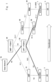
- a Handover Cancel procedure for the Handover procedure from the 5GS to the EPS occurs at any timing from when a Handover Required message illustrated in step 3 in Fig. 17 is transmitted from the NG-RAN 5 to the AMF 10 to when a Handover Command message illustrated in step 20 is transmitted from the NG-RAN 5 to the UE 3.
- the Handover Cancel procedure starts in response to a decision of Handover Cancel by the NG-RAN 5 at a timing in step 18.
- the decision of the Handover Cancel may be referred to as a decision of cancel of the Handover procedure.
- steps 19 and 20 an operation of transmitting the Handover Command message to the UE 3 in steps 19 and 20 is illustrated, but, when the NG-RAN 5 decides the Handover Cancel in step 18, at least step 20 is not performed.
- steps 19 and 20 are illustrated for the sake of convenience in the description of the Handover Cancel procedure.
- Step (1) The UE 3 communicates with the data network 70 via the NG-RAN 5.
- the UE 3 may construct one or a plurality of PDU sessions.
- Step (2) The NG-RAN 5 decides Handover of communication with the UE 3 to the E-UTRAN 7.
- the NG-RAN 5 decides that signal degradation occurs by monitoring a communication state with the UE 3, and the NG-RAN 5 decides Handover of the communication with the UE 3 to the E-UTRAN 7.
- the NG-RAN 5 may decide Handover of the communication with the UE 3 to the E-UTRAN 7.
- the signal degradation described above occurs when the UE 3 leaves a coverage of the NG-RAN 5 by moving from the coverage, and the like.
- the NG-RAN 5 may be referred to as a source RAN device, a source RAN node, a source RAN, a source RAN associated with the 5GS, a source RAN device associated with the 5GS, or a source RAN node associated with the 5GS.
- the AMF 10 may be referred to as a source AMF, a source core network device, a source core network node, a source core network device associated with the 5GS, or a source core network node associated with the 5GS.
- Step (4) The AMF 10 that receives the Handover Required message from the NG-RAN 5 transmits an Nsmf_PDUSession_Context Request to the SMF+PGW-C 40, and notifies activation of Handover to the EPS.
- the SMF+PGW-C 40 and the UPF+PGW-U 30 are located in a home public land mobile network (HPLMN).
- the AMF 10 transmits the Nsmf_PDUSession_Context Request to the V-SMF 80 located in a visited public land mobile network (VPLMN).
- VPN visited public land mobile network
- the V-SMF 80 that receives the Nsmf_PDUSession_Context Request transmits the Nsmf_PDUSession_Context Request to the SMF+PGW-C 40.
- the Nsmf_PDUSession_Context Request may be referred to as an Nsmf_PDUSession_Context Request message.
- the resource may be referred to as a session resource.
- the UPF+PGW-U 30 that receives the instruction secures the resource for the transmission using the EPS. For example, when the UPF+PGW-U 30 secures the resource, the UPF+PGW-U 30 may notify the SMF+PGW-C 40 that the resource is secured.
- the UPF+PGW-U 30 may be referred to as a core network device or a core network node.
- the SMF+PGW-C 40 transmits the Nsmf_PDUSession_Context Response to the V-SMF 80.
- the V-SMF 80 that receives the Nsmf_PDUSession_Context Response transmits the Nsmf_PDUSession_Context Response to the AMF 10.
- the SMF+PGW-C 40 may transmit the Nsmf_PDUSession_Context Response to the AMF 10 or the V-SMF 80.
- the Nsmf_PDUSession_Context Response may be referred to as an Nsmf_PDUSession_Context Response message.
- the AMF 10 may transmit the Relocation Request message to the MME 20.
- the MME 20 may be referred to as a target MME, a target core network device, a target core network node, a target core network device associated with the EPS, or a target core network node associated with the EPS.
- a resource for example, a user plane resource
- the MME 20 may transmit the Create Session Request message to the SGW-C 60.
- the SGW-C 60 that receives the Create Session Request message instructs the SGW-U 50 to secure the resource for the communication being used by the UE 3 after the Handover to the EPS.
- the SGW-U 50 that receives the instruction secures the resource for the communication.
- the SGW-U 50 may notify the SGW-C 60 that the resource for the communication is secured.
- the SGW-C 60 transmits a Create Session Response message to the MME 20 after the resource for the communication is secured in the SGW-U 50.
- the SGW-C 60 may transmit the Create Session Response message to the MME 20.
- a resource for example, a user plane resource
- the MME 20 may transmit the Handover Request message to the E-UTRAN 7.
- the E-UTRAN 7 secures the resource for the communication being used by the UE 3 after the Handover to the EPS.
- the E-UTRAN 7 transmits a Handover Request Ack message to the MME 20 after the resource for the communication is secured in the E-UTRAN 7.
- Step (13) The MME 20 determines whether to perform Indirect data forwarding.
- the Indirect data forwarding is a mechanism for transferring user data in such a way that, for example, when Down Link user data transmitted for the UE 3 during execution of Handover arrives at the NG-RAN 5 being a Handover source, the Down Link user data are transmitted to the UE 3 via the SGW-U 50 and the E-UTRAN 7 being a Handover destination.
- the MME 20 When the MME 20 determines that the Indirect data forwarding is performed, the MME 20 transmits a Create Indirect data forwarding tunnel request message to the SGW-C 60, and provides an instruction to secure, in the SGW-U 50, a resource (for example, a resource for a tunnel in which user data are transferred) for performing the Indirect data forwarding.
- the SGW-C 60 that receives the Create Indirect data forwarding tunnel request message instructs the SGW-U 50 to secure the resource for performing the Indirect data forwarding.
- the SGW-U 50 secures the resource for performing the Indirect data forwarding.
- the SGW-U 50 may notify the SGW-C 60 that the resource for performing the Indirect data forwarding is secured.
- the SGW-C 60 transmits a Create Indirect data forwarding tunnel Response message to the MME 20 after the resource for performing the Indirect data forwarding is secured in the SGW-U 50.
- the SGW-C 60 may transmit the Create Indirect data forwarding tunnel Response message to the MME 20.
- VPN public land mobile network
- the V-SMF 80 that receives the Nsmf_PDUSession_Context Request transmits the Nsmf_PDUSession_Context Request to the SMF+PGW-C 40.
- the Nsmf_PDUSession_Context Request may be referred to as an Nsmf_PDUSession_Context Request message.
- the AMF 10 may transmit an Nsmf_PDUSession_UpdateSMContext Request instead of the Nsmf_PDUSession_Context Request to the SMF+PGW-C 40.
- the AMF 10 may transmit the Nsmf_PDUSession_UpdateSMContext Request instead of the Nsmf_PDUSession_Context Request to the V-SMF 80.
- the V-SMF 80 that receives the Nsmf_PDUSession_UpdateSMContext Request transmits the Nsmf_PDUSession_UpdateSMContext Request to the SMF+PGW-C 40.
- the Nsmf_PDUSession_UpdateSMContext Request may be referred to as an Nsmf_PDUSession_UpdateSMContext Request message.
- Step (16): The SMF+PGW-C 40 that receives the Nsmf_PDUSession_Context Request instructs the UPF+PGW-U 30 to secure the resource (for example, the resource for the tunnel in which the user data are transferred) for performing the Indirect data forwarding. Further, the SMF+PGW-C 40 that receives the Nsmf_PDUSession_UpdateSMContext Request may instruct the UPF+PGW-U 30 to secure the resource (for example, the resource for the tunnel in which the user data are transferred) for performing the Indirect data forwarding. The UPF+PGW-U 30 that receives the instruction secures the resource for the Indirect data forwarding. For example, when the UPF+PGW-U 30 secures the resource for the Indirect data forwarding, the UPF+PGW-U 30 may notify the SMF+PGW-C 40 that the resource is secured.
- the SMF+PGW-C 40 transmits the Nsmf_PDUSession_Context Response to the V-SMF 80.
- the V-SMF 80 that receives the Nsmf_PDUSession_Context Response transmits the Nsmf_PDUSession_Context Response to the AMF 10.
- the SMF+PGW-C 40 may transmit the Nsmf_PDUSession_Context Response to the AMF 10 or the V-SMF 80.
- the SMF+PGW-C 40 may transmit an Nsmf_PDUSession_UpdateSMContext Response instead of the Nsmf_PDUSession_Context Response to the AMF 10.
- the SMF+PGW-C 40 may transmit the Nsmf_PDUSession_UpdateSMContext Response instead of the Nsmf_PDUSession_Context Response to the V-SMF 80.
- the V-SMF 80 that receives the Nsmf_PDUSession_UpdateSMContext Response transmits the Nsmf_PDUSession_UpdateSMContext Response to the AMF 10.
- the Nsmf_PDUSession_UpdateSMContext Response may be referred to as an Nsmf_PDUSession_UpdateSMContext Response message.
- Step (18): The NG-RAN 5 decides cancel of the Handover procedure during activation for the UE 3.
- the NG-RAN 5 can confirm that a signal of the UE 3 is strongly received in the NG-RAN 5, and the NG-RAN 5 determines that the NG-RAN 5 can continue the communication with the UE 3, and the like, the NG-RAN 5 decides the cancel of the Handover procedure during the activation for the UE 3.
- step 18 in Fig. 17 is the same as step 1 in Fig. 18 and step 1 in Fig. 19 .
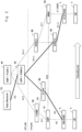
- the Handover Cancel procedure for the Handover procedure from the 5GS to the EPS will be described by using Fig. 18 .
- the first aspect discloses that release of a resource being secured in the UPF+PGW-U 30 is performed when the AMF 10 receives a Handover Cancel message from the NG-RAN 5.
- the Handover Cancel procedure is included in the Handover procedure.
- Step (1) The NG-RAN 5 decides cancel of the Handover procedure during activation for the UE 3. For example, the NG-RAN 5 decides to perform the Handover Cancel procedure.
- Step (2) The NG-RAN 5 transmits the Handover Cancel message to the AMF 10.
- the NG-RAN 5 may transmit the Handover Cancel message to the AMF 10.
- the Handover Cancel message may be referred to as a message for canceling handover from the 5GS to the EPS.
- Step (3) The AMF 10 that receives the Handover Cancel message from the NG-RAN 5 transmits an Nsmf_PDUSession_UpdateSMContext Request to the SMF+PGW-C 40, and notifies cancel of handover to the EPS.
- a Relocation Cancel Indication is set in the Nsmf_PDUSession_UpdateSMContext Request.
- the Relocation Cancel Indication is an indication that notifies the SMF+PGW-C 40 that Handover is canceled and the UE 3 continues the communication by using the NG-RAN 5, and may be indication information for releasing a resource being secured for the Handover.
- the AMF 10 transmits the Nsmf_PDUSession_UpdateSMContext Request to the V-SMF 80 located in a visited public land mobile network (VPLMN).
- the V-SMF 80 that receives the Nsmf_PDUSession_UpdateSMContext Request transmits the Nsmf_PDUSession_UpdateSMContext Request to the SMF+PGW-C 40.
- the Nsmf_PDUSession_UpdateSMContext Request may be referred to as an Nsmf_PDUSession_UpdateSMContext Request message.
- the SMF+PGW-C 40 may delete or release a session resource being secured in the SMF+PGW-C 40 and the UPF+PGW-U 30 during a Handover Preparation procedure, based on the Relocation Cancel Indication.
- the secured resource is the resource being secured by the UPF+PGW-U 30 in step (5) in Fig. 17 for the transmission using the EPS. Further, the secured resource may include the resource being secured by the UPF+PGW-U 30 in step (16) in Fig. 17 for the Indirect data forwarding.
- the SMF+PGW-C 40 may instruct the UPF+PGW-U 30 to release the resource being secured for the transmission using the EPS and the resource being secured for the Indirect data forwarding.
- the UPF+PGW-U 30 that receives the instruction of the resource release releases the secured resource.
- the Nsmf_PDUSession_UpdateSMContext Request may be referred to as a message for the resource release. Further, for example, when the UPF+PGW-U 30 releases the resource, the UPF+PGW-U 30 may notify the SMF+PGW-C 40 that the resource is released.
- the SMF+PGW-C 40 transmits the Nsmf_PDUSession_UpdateSMContext Response to the V-SMF 80.
- the V-SMF 80 that receives the Nsmf_PDUSession_UpdateSMContext Response transmits the Nsmf_PDUSession_UpdateSMContext Response to the AMF 10.
- the SMF+PGW-C 40 may transmit the Nsmf_PDUSession_UpdateSMContext Response to the AMF 10 or the V-SMF 80.
- the Nsmf_PDUSession_UpdateSMContext Response may be referred to as an Nsmf_PDUSession_UpdateSMContext Response message.
- Step (6) The AMF 10 transmits a Relocation Cancel Request message to the MME 20.
- the AMF 10 may transmit the Relocation Cancel Request message to the MME 20.
- the Relocation Cancel Request may be referred to as a message for releasing a resource of the E-UTRAN 7.
- the Relocation Cancel Request may be referred to as a message for releasing a resource of the SGW-U 50.
- the Relocation Cancel Request may be referred to as a message for releasing a resource of the EPS.
- Step (7) The MME 20 performs an S 1 Release procedure between the E-UTRAN 7 and the MME 20 in order to release a resource being secured in the E-UTRAN 7.
- the MME 20 may perform the S1 Release procedure.
- the secured resource is the resource being secured by the E-UTRAN 7 in steps (11 and 12) in Fig. 17 .
- the E-UTRAN 7 releases the secured resource in the S1 Release procedure.
- the E-UTRAN 7 may notify the MME 20 that the resource is released.
- Step (8) The MME 20 transmits a Delete Session Request message to the SGW-C 60.
- the MME 20 may transmit the Delete Session Request message to the SGW-C 60.
- the S1 Release procedure in step (7) is completed (for example, when the MME 20 receives, from the E-UTRAN 7, the notification indicating that the resource being secured by the E-UTRAN 7 in steps (11 and 12) in Fig. 17 is released)
- the MME 20 may transmit the Delete Session Request message to the SGW-C 60.
- the SGW-C 60 that receives the Delete Session Request message instructs the SGW-U 50 to release the resource being secured in the SGW-U 50.
- the secured resource is the resource being secured by the SGW-U 50 in steps (8 to 10) in Fig. 17 .
- the SGW-U 50 that receives the instruction releases the resource being secured in the SGW-U 50.
- the SGW-C 60 transmits a Delete Session Response message to the MME 20. For example, when the SGW-C 60 receives the notification indicating that the resource is released, the SGW-C 60 may transmit the Delete Session Response message to the MME 20.
- Step (9) The MME 20 transmits a Relocation Cancel Response message to the AMF 10. For example, when the MME 20 receives the Delete Session Response message, the MME 20 may transmit the Relocation Cancel Response message to the AMF 10.
- Step (10) The AMF 10 transmits a Handover Cancel ACK message to the NG-RAN 5. For example, when the AMF 10 receives the Relocation Cancel Response message, the AMF 10 may transmit the Handover Cancel ACK message to the NG-RAN 5.
- Step (11) When the resource for performing the Indirect data forwarding is secured, the MME 20 transmits a Delete Indirect Data Forwarding Tunnel Request message to the SGW-C 60.
- the SGW-C 60 that receives the Delete Indirect Data Forwarding Tunnel Request message instructs the SGW-U 50 to release the resource being secured for performing the Indirect data forwarding in the SGW-U 50.
- the SGW-U 50 that receives the instruction releases the resource for performing the Indirect data forwarding. For example, the SGW-U 50 may notify the SGW-C 60 that the resource for performing the Indirect data forwarding is released.
- the SGW-C 60 transmits the Delete Indirect Data Forwarding Tunnel Response message to the MME 20 after the resource for performing the Indirect data forwarding is released.
- the SGW-C 60 may transmit the Delete Indirect Data Forwarding Tunnel Response message to the MME 20.
- the present disclosure is able to provide a method of appropriately managing a resource for user data control. Specifically, by performing the procedure described above, all resources being secured in the Handover procedure from the 5GS to the EPS can be released. For example, even when the Handover procedure from the 5GS to the EPS is canceled, all resources for user data control being set in the Handover procedure can be released. Further, for example, a resource being secured in the UPF+PGW-U 30 in the Handover procedure from the 5GS to the EPS can be released. Further, for example, a resource being secured for performing the Indirect data forwarding in the Handover procedure from the 5GS to the EPS can be released.
- a resource securing procedure in the Handover procedure from the 5GS to the EPS, and a release procedure of the resource in the Handover Cancel procedure become clear, and the Handover procedure and the Handover Cancel procedure having high quality in consideration of a difference in the GTP-U header being used in the 5GS and the EPS can be provided.
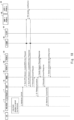
- Fig. 19 An example of the Handover Cancel procedure for the Handover procedure from the 5GS to the EPS will be described by using Fig. 19 .
- the second aspect discloses that release of a resource being secured in the UPF+PGW-U 30 is performed when the AMF 10 transmits a Handover Cancel ACK message to the NG-RAN 5.
- Step (1) The NG-RAN 5 decides cancel of the Handover procedure during activation for the UE 3. For example, the NG-RAN 5 decides to perform the Handover Cancel procedure.
- Step (2) The NG-RAN 5 transmits a Handover Cancel message to the AMF 10.
- the NG-RAN 5 may transmit the Handover Cancel message to the AMF 10.
- the Handover Cancel message may be referred to as a message for canceling handover from the 5GS to the EPS.
- Step (3) The AMF 10 transmits a Relocation Cancel Request message to the MME 20.
- the AMF 10 may transmit the Relocation Cancel Request message to the MME 20.
- Step (4) The MME 20 performs an S1 Release procedure between the MME 20 and the E-UTRAN 7 in order to release a resource being secured in the E-UTRAN 7.
- the secured resource is the resource being secured by the E-UTRAN 7 in steps (11 and 12) in Fig. 17 .
- the E-UTRAN 7 releases the secured resource in the S1 Release procedure. For example, when the E-UTRAN 7 releases the secured resource, the E-UTRAN 7 may notify the MME 20 that the resource is released.
- the SGW-C 60 that receives the Delete Session Request message instructs the SGW-U 50 to release the resource being secured in the SGW-U 50.
- the secured resource is the resource being secured by the SGW-U 50 in steps (8 to 10) in Fig. 17 .
- the SGW-U 50 that receives the instruction releases the resource being secured in the SGW-U 50.
- the SGW-C 60 transmits a Delete Session Response message to the MME 20. For example, when the SGW-C 60 receives the notification indicating that the resource is released, the SGW-C 60 may transmit the Delete Session Response message to the MME 20.
- Step (6) The MME 20 transmits a Relocation Cancel Response message to the AMF 10. For example, when the MME 20 receives the Delete Session Response message, the MME 20 may transmit the Relocation Cancel Response message to the AMF 10.
- Step (7) The AMF 10 transmits the Handover Cancel ACK message to the NG-RAN 5. For example, when the AMF 10 receives the Relocation Cancel Response message, the AMF 10 may transmit the Handover Cancel ACK message to the NG-RAN 5.
- a Relocation Cancel Indication is set in the Nsmf_PDUSession_UpdateSMContext Request.
- the AMF 10 transmits the Nsmf_PDUSession_UpdateSMContext Request to the V-SMF 80 located in a visited public land mobile network (VPLMN).
- the Nsmf_PDUSession_UpdateSMContext Request may be referred to as an Nsmf_PDUSession_UpdateSMContext Request message.
- the V-SMF 80 that receives the Nsmf_PDUSession_UpdateSMContext Request transmits the Nsmf_PDUSession_UpdateSMContext Request to the SMF+PGW-C 40.
- the secured resource is the resource being secured by the UPF+PGW-U 30 in step (5) in Fig. 17 for the transmission using the EPS. Further, the secured resource may include the resource being secured by the UPF+PGW-U 30 in step (16) in Fig. 17 for the Indirect data forwarding.
- the SMF+PGW-C 40 may instruct the UPF+PGW-U 30 to release the resource being secured for the transmission using the EPS and the resource for the Indirect data forwarding.
- the UPF+PGW-U 30 that receives the instruction of the resource release releases the secured resource.
- the Nsmf_PDUSession_UpdateSMContext Request may be referred to as a message for the resource release. Further, for example, when the UPF+PGW-U 30 releases the resource, the UPF+PGW-U 30 may notify the SMF+PGW-C 40 that the resource is released.
- the SMF+PGW-C 40 transmits the Nsmf_PDUSession_UpdateSMContext Response to the V-SMF 80.
- the V-SMF 80 that receives the Nsmf_PDUSession_UpdateSMContext Response transmits the Nsmf_PDUSession_UpdateSMContext Response to the AMF 10.
- the SMF+PGW-C 40 may transmit the Nsmf_PDUSession_UpdateSMContext Response to the AMF 10 or the V-SMF 80.
- the Nsmf_PDUSession_UpdateSMContext Response may be referred to as an Nsmf_PDUSession_UpdateSMContext Response message.
- Step (11) When the resource for performing the Indirect data forwarding is secured (for example, when an indirect forwarding tunnel is set during the Handover Preparation procedure), the MME 20 transmits a Delete Indirect Data Forwarding Tunnel Request message to the SGW-C 60.
- the SGW-C 60 that receives the Delete Indirect Data Forwarding Tunnel Request message instructs the SGW-U 50 to release the resource being secured for performing the Indirect data forwarding in the SGW-U 50 during the Handover Preparation procedure.
- the SGW-U 50 that receives the instruction releases the resource for performing the Indirect data forwarding. For example, the SGW-U 50 may notify the SGW-C 60 that the resource for performing the Indirect data forwarding is released.
- the SGW-C 60 transmits the Delete Indirect Data Forwarding Tunnel Response message to the MME 20 after the resource for performing the Indirect data forwarding is released. For example, when the SGW-C 60 receives, from the SGW-U 50, the notification indicating that the resource for performing the Indirect data forwarding is released, the SGW-C 60 may transmit the Delete Indirect Data Forwarding Tunnel Response message to the MME 20.
- the present disclosure is able to provide a method of appropriately managing a resource for user data control.
- all resources being secured in the Handover procedure from the 5GS to the EPS can be released.
- all resources for user data control being set in the Handover procedure can be released.
- a resource being secured in the UPF+PGW-U 30 in the Handover procedure from the 5GS to the EPS can be released.
- a resource being secured for performing the Indirect data forwarding in the Handover procedure from the 5GS to the EPS can be released.
- a resource securing procedure in the Handover procedure from the 5GS to the EPS, and a release procedure of the resource in the Handover Cancel procedure become clear, and the Handover procedure and the Handover Cancel procedure having high quality in consideration of a difference in the GTP-U header being used in the 5GS and the EPS can be provided.
- AMF Access and Mobility management Function
- the core network device is a User Plane Function (UPF) device.
- UPF User Plane Function
- a source core network node comprising:
- the source core network node according to Supplementary note 10, wherein the first message is a Handover Cancel message.
- the source core network node according to Supplementary note 10 or 11, wherein the second message is a Relocation Cancel Request message.
- the source core network node according to any one of Supplementary notes 10 to 12, wherein the third message is a Relocation Cancel Response message.
- the source core network node according to any one of Supplementary notes 10 to 13, wherein the fourth message is a Handover Cancel ACK message.
- the source core network node according to any one of Supplementary notes 10 to 14, wherein the fifth message is a Nsmf_PDUSession_UpdateSMContext Request message.
- the source core network node according to any one of Supplementary notes 10 to 15, wherein the source core network node is an Access and Mobility management Function (AMF) device.
- AMF Access and Mobility management Function
- the source core network node according to any one of Supplementary notes 10 to 16, wherein the fifth message is transmitted to a Session Management Function (SMF) device.
- SMS Session Management Function
- the source core network node according to any one of Supplementary notes 10 to 17, wherein the core network device is a User Plane Function (UPF) device.
- the core network device is a User Plane Function (UPF) device.
- UPF User Plane Function
- a non-transitory computer-readable medium recording a program for causing a computer configured to control a source core network node to execute a method, the method including:
Landscapes
- Engineering & Computer Science (AREA)
- Signal Processing (AREA)
- Computer Networks & Wireless Communication (AREA)
- Computer Security & Cryptography (AREA)
- Mobile Radio Communication Systems (AREA)
Abstract
Description
- The present disclosure relates to a method for a source core network node and the source core network node.
- In a telecommunications field, an effort of achieving a new generation network called a fifth-generation (5G) network has been made. In order to develop the 5G network that provides a service for various terminals, activities have been started in a plurality of research and standardization organizations. Particularly, a third-generation partnership project (3GPP) has been examining a next-generation communication technique and a system architecture for the 5G network being a next-generation mobile communication system. Particularly, in the 3GPP, a 5G system (5GS) has been specified as a system for achieving the 5G mobile communication system. Specifications of the 5GS are disclosed in, for example,
Non Patent Literature 1 andNon Patent Literature 2. - As one of main characteristics of the 5GS, a concept of "flow" is adopted as a method for transmitting user data in the 5GS. In user data transmission by a bearer adopted in an evolved packet system (EPS), a transmission node and a reception node each manage a tunnel for the user data transmission, and control quality of service (QoS), however, in flow control, a QoS flow identifier (QFI) is set for a header of packet data that transmits user data, and control of the QoS is performed in a flow unit.
-
- [Non Patent Literature 1] 3GPP TS 23.501 V16.7.0 (2020-12)
- [Non Patent Literature 2] 3GPP TS 23.502 V16.7.1 (2021-01)
- Service succession with an EPS is stipulated in the 5GS. This is a technique for successively providing a service even when user equipment (UE) moves from a 4G to a 5G or from the 5G to the 4G since it is assumed that the 5G is introduced from an urban area in a spot manner in contrast to the 4G that covers a wide area. This technique is provided by an interworking procedure. The interworking procedure includes 5GS to EPS handover, EPS to 5GS handover, and the like.
- While user data transmission is managed by using a bearer in the EPS, the user data transmission is managed by using a flow in the 5GS. Depending on a difference in this management method, there is a difference in header information of a GPRS tunneling protocol for user plane (GTP-U) being a protocol for performing user data transmission. For example, a QFI is set for a GTP-U header being used in the 5GS, but the QFI is not set in the EPS.
- When handover is operated in the 5GS and the EPS, user data need to be controlled in careful consideration of a difference in the GTP-U header being used in the 5GS and the EPS. The procedure is disclosed in
Non Patent Literature 2, but an operation and a procedure of each node are ambiguous. Thus, there is a problem that a resource for user data control cannot be appropriately managed when handover is canceled, for example. - The present disclosure provides a method of appropriately managing a resource for user data control.
- A method for a source core network node according to one aspect of the present disclosure includes: receiving, from a source radio access network (RAN) associated with a 5G system (5GS), a first message for canceling handover of a terminal from the 5GS to an evolved packet system (EPS); transmitting a second message to a target core network node associated with the EPS when receiving the first message; receiving a third message from the target core network node when transmitting the second message; transmitting a fourth message to the source RAN when receiving the third message; and transmitting a fifth message for releasing a resource being secured in a core network device when transmitting the fourth message.
- A source core network node according to one aspect of the present disclosure includes: a reception means for receiving, from a source radio access network (RAN) associated with a 5G system (5GS), a first message for canceling handover of a terminal from the 5GS to an evolved packet system (EPS); and a transmission means for transmitting a second message to a target core network node associated with the EPS when receiving the first message, wherein the reception means receives a third message from the target core network node when transmitting the second message, the transmission means transmits a fourth message to the source RAN when receiving the third message, and the transmission means transmits a fifth message for releasing a resource being secured in a core network device when transmitting the fourth message.
- The present disclosure is able to provide a method of appropriately managing a resource for user data control.
-
-
Fig. 1 is a schematic configuration diagram of a cellular network according to each aspect; -
Fig. 2 is a schematic configuration diagram of a cellular network in a case of home-routed roaming according to each aspect; -
Fig. 3 is a configuration diagram of an NG-RAN according to each aspect; -
Fig. 4 is a block diagram illustrating a configuration example of the NG-RAN according to each aspect; -
Fig. 5 is a configuration diagram of an AMF according to each aspect; -
Fig. 6 is a block diagram illustrating a configuration example of the AMF according to each aspect; -
Fig. 7 is a configuration diagram of an MME according to each aspect; -
Fig. 8 is a block diagram illustrating a configuration example of the MME according to each aspect; -
Fig. 9 is a configuration diagram of a UPF+PGW-U according to each aspect; -
Fig. 10 is a block diagram illustrating a configuration example of the UPF+PGW-U according to each aspect; -
Fig. 11 is a configuration diagram of an SMF+PGW-C according to each aspect; -
Fig. 12 is a block diagram illustrating a configuration example of the SMF+PGW-C according to each aspect; -
Fig. 13 is a configuration diagram of an SGW-C according to each aspect; -
Fig. 14 is a block diagram illustrating a configuration example of the SGW-C according to each aspect; -
Fig. 15 is a configuration diagram of a V-SMF according to each aspect; -
Fig. 16 is a block diagram illustrating a configuration example of the V-SMF according to each aspect; -
Fig. 17 is a diagram illustrating a procedure of Handover Preparation common to a first aspect and a second aspect; -
Fig. 18 is a diagram illustrating a procedure of Handover Cancel according to the first aspect; and -
Fig. 19 is a diagram illustrating a procedure of Handover Cancel according to the second aspect. - In a procedure of UE performing Handover from a new radio (NR) being a wireless access technique of a 5G to long term evolution (LTE) or LTE-Advanced being a wireless access technique of a 4G, an operation in which the UE returns to the 5G (NR) in the middle of the Handover processing is stipulated as a Handover Cancel procedure in
Non Patent Literature 2. Note that a procedure of performing Handover from the NR to LTE or LTE-Advanced may be referred to as a Handover procedure from a 5GS to an EPS. Further, a procedure of performing Handover from the NR to LTE or LTE-Advanced may be referred to as Handover of a terminal from the 5GS to the EPS. - However, in the Handover Cancel procedure in
Non Patent Literature 2, an operation and a procedure of each node are ambiguous. There is a problem that a resource for user data control cannot be appropriately managed when Handover is canceled (that is, when the Handover Cancel procedure is performed), for example. Specifically, as described above, when Handover is operated in the 5GS and the EPS, user data need to be controlled in careful consideration of a difference in a GTP-U header being used in the 5GS and the EPS. For the user data control, a resource for the user data control is secured in a UPF+PGW-U 30 and an SMF+PGW-C 40. Examples of the resource include a physical resource that recognizes a difference in the GTP-U header described above, and a physical resource that appropriately controls and transfers user data, based on a difference in the GTP-U header. - Herein, for example, when the Handover Cancel procedure for the Handover procedure from the 5GS to the EPS is performed, the resource for the user data control described above needs to be released, but the release of the resource is not mentioned at all in the Handover Cancel procedure described in
Non Patent Literature 2. In other words, the resource for the user data control described above is still secured after the Handover Cancel procedure described inNon Patent Literature 2 is completed. There is a risk that such an unnecessarily secured resource hinders a cellular network. - Thus, the present disclosure indicates a technique for appropriately releasing a resource for user data control being set by the Handover procedure from the 5GS to the EPS in the Handover Cancel procedure for the Handover procedure.
- A mobile communication system according to the present disclosure will be described with reference to the drawings.
-
Figs. 1 and2 illustrate a configuration example of a cellular network according to the present disclosure. Each element illustrated inFigs. 1 and2 is a network function, and provides an interface defined by a 3rd generation partnership project (3GPP). For example, each element (network function) illustrated inFigs. 1 and2 can be implemented as a network element on dedicated hardware, as a software instance running on the dedicated hardware, or as a virtualized function being instantiated on an application platform. -
Fig. 3 illustrates a configuration example of a next generation radio access network (NG-RAN) 5. Note that the NG-RAN 5 may be referred to as an NG-RAN node, for example. The NG-RAN 5 may be referred to as a source radio access network (RAN) associated with a 5GS. The NG-RAN 5 includes acommunication unit 51 and acontrol unit 52. Thecommunication unit 51 and thecontrol unit 52 may be software or a module whose processing is performed by a processor executing a program stored in a memory. Alternatively, thecommunication unit 51 and thecontrol unit 52 may be a circuit or hardware such as a chip. - The
communication unit 51 is a functional unit for the NG-RAN 5 to be connected to a core network device included in an access network and a core network. In other words, the NG-RAN 5 can transmit and receive user data and/or control information to and from the core network device included in the access network and/or the core network via thecommunication unit 51. Note that the core network device may be referred to as a core network node. - The
control unit 52 is a functional unit for controlling the NG-RAN 5, and achieves various types of processing of the entire NG-RAN 5 by reading and executing various types of information and programs being stored in a memory. - Details of the configuration example of the NG-
RAN 5 described in a plurality of aspects described below will be described by usingFig. 4 . -
Fig. 4 is a block diagram illustrating the configuration example of the NG-RAN 5. With reference toFig. 4 , the NG-RAN 5 includes anetwork interface 501, aprocessor 502, and amemory 503. Thenetwork interface 501 is used for communicating with another network node device constituting a communication system. Thenetwork interface 501 may include, for example, a network interface card (NIC) conforming to IEEE 802.3 series. - The
processor 502 performs processing of the NG-RAN 5 described by using a sequence diagram in the aspects described below by reading software (computer program) from thememory 503 and executing the software. Theprocessor 502 may be, for example, a microprocessor, a micro processing unit (MPU), or a central processing unit (CPU). Theprocessor 502 may include a plurality of processors. - The
memory 503 is formed of a combination of a volatile memory and a non-volatile memory. Thememory 503 may include a storage disposed away from theprocessor 502. In this case, theprocessor 502 may access thememory 503 via an I/O interface that is not illustrated. - In the example in
Fig. 4 , thememory 503 is used for storing a software module group. Theprocessor 502 can perform the processing of the NG-RAN 5 described in the aspects described below by reading the software module group from thememory 503 and executing the software module group. - As described by using
Fig. 4 , each processor included in the NG-RAN 5 executes one or a plurality of programs including a command group for causing a computer to perform an algorithm described by using the drawings. -
Fig. 5 illustrates a configuration example of an access andmobility management function 10. TheAMF 10 may be referred to as an AMF device. TheAMF 10 may be referred to as a core network node associated with the 5GS. TheAMF 10 includes acommunication unit 11 and acontrol unit 12. Thecommunication unit 11 and thecontrol unit 12 may be software or a module whose processing is performed by a processor executing a program stored in a memory. Alternatively, thecommunication unit 11 and thecontrol unit 12 may be a circuit or hardware such as a chip. - The
communication unit 11 is a functional unit for theAMF 10 to be connected to a core network device included in an access network and a core network. In other words, theAMF 10 can transmit and receive user data and/or control information to and from the core network device included in the access network and/or the core network via thecommunication unit 11. - The
control unit 12 is a functional unit for controlling theAMF 10, and achieves various types of processing of theentire AMF 10 by reading and executing various types of information and programs being stored in a memory. - Details of the configuration example of the
AMF 10 described in the plurality of aspects described below will be described by usingFig. 6 . -
Fig. 6 is a block diagram illustrating the configuration example of theAMF 10. With reference toFig. 6 , theAMF 10 includes anetwork interface 1001, aprocessor 1002, and amemory 1003. Thenetwork interface 1001 is used for communicating with another network node device constituting a communication system. Thenetwork interface 1001 may include, for example, a network interface card (NIC) conforming to IEEE 802.3 series. - The
processor 1002 performs processing of theAMF 10 described by using a sequence diagram in the aspects described below by reading software (computer program) from thememory 1003 and executing the software. Theprocessor 1002 may be, for example, a microprocessor, a micro processing unit (MPU), or a central processing unit (CPU). Theprocessor 1002 may include a plurality of processors. - The
memory 1003 is formed of a combination of a volatile memory and a non-volatile memory. Thememory 1003 may include a storage disposed away from theprocessor 1002. In this case, theprocessor 1002 may access thememory 1003 via an I/O interface that is not illustrated. - In the example in
Fig. 6 , thememory 1003 is used for storing a software module group. Theprocessor 1002 can perform the processing of theAMF 10 described in the aspects described below by reading the software module group from thememory 1003 and executing the software module group. - As described by using
Fig. 6 , each processor included in theAMF 10 executes one or a plurality of programs including a command group for causing a computer to perform an algorithm described by using the drawings. -
Fig. 7 illustrates a configuration example of a mobile management entity (MME) 20. TheMME 20 may be referred to as an MME device. TheMME 20 may be referred to as a core network node associated with the EPS. TheMME 20 includes acommunication unit 21 and acontrol unit 22. Thecommunication unit 21 and thecontrol unit 22 may be software or a module whose processing is performed by a processor executing a program stored in a memory. Alternatively, thecommunication unit 21 and thecontrol unit 22 may be a circuit or hardware such as a chip. - The
communication unit 21 is a functional unit for theMME 20 to be connected to a core network device included in an access network and a core network. In other words, theMME 20 can transmit and receive user data and/or control information to and from the core network device included in the core network via thecommunication unit 21. - The
control unit 22 is a functional unit for controlling theMME 20, and achieves various types of processing of theentire MME 20 by reading and executing various types of information and programs being stored in a memory. - Details of the configuration example of the
MME 20 described in the plurality of aspects described below will be described by usingFig. 8 . -
Fig. 8 is a block diagram illustrating the configuration example of theMME 20. With reference toFig. 8 , theMME 20 includes anetwork interface 2001, aprocessor 2002, and amemory 2003. Thenetwork interface 2001 is used for communicating with another network node device constituting a communication system. Thenetwork interface 2001 may include, for example, a network interface card (NIC) conforming to IEEE 802.3 series. - The
processor 2002 performs processing of theMME 20 described by using a sequence diagram in the aspects described below by reading software (computer program) from thememory 2003 and executing the software. Theprocessor 2002 may be, for example, a microprocessor, a micro processing unit (MPU), or a central processing unit (CPU). Theprocessor 2002 may include a plurality of processors. - The
memory 2003 is formed of a combination of a volatile memory and a non-volatile memory. Thememory 2003 may include a storage disposed away from theprocessor 2002. In this case, theprocessor 2002 may access thememory 2003 via an I/O interface that is not illustrated. - In the example in
Fig. 8 , thememory 2003 is used for storing a software module group. Theprocessor 2002 can perform the processing of theMME 20 described in the aspects described below by reading the software module group from thememory 2003 and executing the software module group. - As described by using
Fig. 8 , each processor included in theMME 20 executes one or a plurality of programs including a command group for causing a computer to perform an algorithm described by using the drawings. -
Fig. 9 illustrates a configuration example of a user plane function + packet data network gateway-U (UPF+PGW-U) 30. The UPF+PGW-U 30 may be referred to as a UPF+PGW-U device. The UPF+PGW-U 30 may be referred to as a user plane device or a core network device. The UPF+PGW-U 30 includes acommunication unit 31 and acontrol unit 32. Thecommunication unit 31 and thecontrol unit 32 may be software or a module whose processing is performed by a processor executing a program stored in a memory. Alternatively, thecommunication unit 31 and thecontrol unit 32 may be a circuit or hardware such as a chip. - The
communication unit 31 is a functional unit for the UPF+PGW-U 30 to be connected to a core network device included in an access network and a core network. In other words, the UPF+PGW-U 30 can transmit and receive user data and/or control information to and from the core network device included in the core network via thecommunication unit 31. - The
control unit 32 is a functional unit for controlling the UPF+PGW-U 30, and achieves various types of processing of the entire UPF+PGW-U 30 by reading and executing various types of information and programs being stored in a memory. - Details of the configuration example of the UPF+PGW-
U 30 described in the plurality of aspects described below will be described by usingFig. 10 . -
Fig. 10 is a block diagram illustrating the configuration example of the UPF+PGW-U 30. With reference toFig. 10 , the UPF+PGW-U 30 includes anetwork interface 3001, aprocessor 3002, and amemory 3003. Thenetwork interface 3001 is used for communicating with another network node device constituting a communication system. Thenetwork interface 3001 may include, for example, a network interface card (NIC) conforming to IEEE 802.3 series. - The
processor 3002 performs processing of the UPF+PGW-U 30 described by using a sequence diagram in the aspects described below by reading software (computer program) from thememory 3003 and executing the software. Theprocessor 3002 may be, for example, a microprocessor, a micro processing unit (MPU), or a central processing unit (CPU). Theprocessor 3002 may include a plurality of processors. - The
memory 3003 is formed of a combination of a volatile memory and a non-volatile memory. Thememory 3003 may include a storage disposed away from theprocessor 3002. In this case, theprocessor 3002 may access thememory 3003 via an I/O interface that is not illustrated. - In the example in
Fig. 10 , thememory 3003 is used for storing a software module group. Theprocessor 3002 can perform the processing of the UPF+PGW-U 30 described in the aspects described below by reading the software module group from thememory 3003 and executing the software module group. - As described by using
Fig. 10 , each processor included in the UPF+PGW-U 30 executes one or a plurality of programs including a command group for causing a computer to perform an algorithm described by using the drawings. -
Fig. 11 illustrates a configuration example of a session management function + packet data network gateway-C (SMF+PGW-C) 40. The SMF+PGW-C 40 may be referred to as a SMF+PGW-C device. The SMF+PGW-C 40 may be referred to as a core network device. The SMF+PGW-C 40 includes acommunication unit 41 and acontrol unit 42. Thecommunication unit 41 and thecontrol unit 42 may be software or a module whose processing is performed by a processor executing a program stored in a memory. Alternatively, thecommunication unit 41 and thecontrol unit 42 may be a circuit or hardware such as a chip. - The
communication unit 41 is a functional unit for the SMF+PGW-C 40 to be connected to a core network device included in an access network and a core network. In other words, the SMF+PGW-C 40 can transmit and receive user data and/or control information to and from the core network device included in the core network via thecommunication unit 41. - The
control unit 42 is a functional unit for controlling the SMF+PGW-C 40, and achieves various types of processing of the entire SMF+PGW-C 40 by reading and executing various types of information and programs being stored in a memory. - Details of the configuration example of the SMF+PGW-
C 40 described in the plurality of aspects described below will be described by usingFig. 12 . -
Fig. 12 is a block diagram illustrating the configuration example of the SMF+PGW-C 40. With reference toFig. 12 , the SMF+PGW-C 40 includes anetwork interface 4001, aprocessor 4002, and amemory 4003. Thenetwork interface 4001 is used for communicating with another network node device constituting a communication system. Thenetwork interface 4001 may include, for example, a network interface card (NIC) conforming to IEEE 802.3 series. - The
processor 4002 performs processing of the SMF+PGW-C 40 described by using a sequence diagram in the aspects described below by reading software (computer program) from thememory 4003 and executing the software. Theprocessor 4002 may be, for example, a microprocessor, a micro processing unit (MPU), or a central processing unit (CPU). Theprocessor 4002 may include a plurality of processors. - The
memory 4003 is formed of a combination of a volatile memory and a non-volatile memory. Thememory 4003 may include a storage disposed away from theprocessor 4002. In this case, theprocessor 4002 may access thememory 4003 via an I/O interface that is not illustrated. - In the example in
Fig. 12 , thememory 4003 is used for storing a software module group. Theprocessor 4002 can perform the processing of the SMF+PGW-C 40 described in the aspects described below by reading the software module group from thememory 4003 and executing the software module group. - As described by using
Fig. 12 , each processor included in the SMF+PGW-C 40 executes one or a plurality of programs including a command group for causing a computer to perform an algorithm described by using the drawings. -
Fig. 13 illustrates a configuration example of a serving gateway control plane function (SGW-C) 60. The SGW-C 60 may be referred to as an SGW-C device. The SGW-C 60 may be referred to as a core network device. The SGW-C 60 includes acommunication unit 61 and acontrol unit 62. Thecommunication unit 61 and thecontrol unit 62 may be software or a module whose processing is performed by a processor executing a program stored in a memory. Alternatively, thecommunication unit 61 and thecontrol unit 12 may be a circuit or hardware such as a chip. - The
communication unit 61 is a functional unit for the SGW-C 60 to be connected to a core network device included in an access network and a core network. In other words, the SGW-C 60 can transmit and receive user data and/or control information to and from the core network device included in the core network via thecommunication unit 61. - The
control unit 62 is a functional unit for controlling the SGW-C 60, and achieves various types of processing of the entire SGW-C 60 by reading and executing various types of information and programs being stored in a memory. - Details of the configuration example of the SGW-
C 60 described in the plurality of aspects described below will be described by usingFig. 14 . -
Fig. 14 is a block diagram illustrating the configuration example of the SGW-C 60. With reference toFig. 14 , the SGW-C 60 includes anetwork interface 6001, aprocessor 6002, and amemory 6003. Thenetwork interface 6001 is used for communicating with another network node device constituting a communication system. Thenetwork interface 6001 may include, for example, a network interface card (NIC) conforming to IEEE 802.3 series. - The
processor 6002 performs processing of the SGW-C 60 described by using a sequence diagram in the aspects described below by reading software (computer program) from thememory 6003 and executing the software. Theprocessor 6002 may be, for example, a microprocessor, a micro processing unit (MPU), or a central processing unit (CPU). Theprocessor 6002 may include a plurality of processors. - The
memory 6003 is formed of a combination of a volatile memory and a non-volatile memory. Thememory 6003 may include a storage disposed away from theprocessor 6002. In this case, theprocessor 6002 may access thememory 6003 via an I/O interface that is not illustrated. - In the example in
Fig. 14 , thememory 6003 is used for storing a software module group. Theprocessor 6002 can perform the processing of the SGW-C 60 described in the aspects described below by reading the software module group from thememory 6003 and executing the software module group. - As described by using
Fig. 14 , each processor included in the SGW-C 60 executes one or a plurality of programs including a command group for causing a computer to perform an algorithm described by using the drawings. -
Fig. 15 illustrates a configuration example of a visited session management function (V-SMF) 80. The V-SMF 80 may be referred to as a V-SMF device. The V-SMF 80 may be referred to as a core network device. The V-SMF 80 includes acommunication unit 81 and acontrol unit 82. Thecommunication unit 81 and thecontrol unit 82 may be software or a module whose processing is performed by a processor executing a program stored in a memory. Alternatively, thecommunication unit 81 and thecontrol unit 82 may be a circuit or hardware such as a chip. - The
communication unit 81 is a functional unit for the V-SMF 80 to be connected to a core network device included in an access network and a core network. In other words, the V-SMF 80 can transmit and receive user data and/or control information to and from the core network device included in the core network via thecommunication unit 81. - The
control unit 82 is a functional unit for controlling the V-SMF 80, and achieves various types of processing of the entire V-SMF 80 by reading and executing various types of information and programs being stored in a memory. - Details of the configuration example of the V-
SMF 80 described in the plurality of aspects described below will be described by usingFig. 16 . -
Fig. 16 is a block diagram illustrating the configuration example of the V-SMF 80. With reference toFig. 16 , the V-SMF 80 includes anetwork interface 8001, aprocessor 8002, and amemory 8003. Thenetwork interface 8001 is used for communicating with another network node device constituting a communication system. Thenetwork interface 8001 may include, for example, a network interface card (NIC) conforming to IEEE 802.3 series. - The
processor 8002 performs processing of the V-SMF 80 described by using a sequence diagram in the aspects described below by reading software (computer program) from thememory 8003 and executing the software. Theprocessor 8002 may be, for example, a microprocessor, a micro processing unit (MPU), or a central processing unit (CPU). Theprocessor 8002 may include a plurality of processors. - The
memory 8003 is formed of a combination of a volatile memory and a non-volatile memory. Thememory 8003 may include a storage disposed away from theprocessor 8002. In this case, theprocessor 8002 may access thememory 8003 via an I/O interface that is not illustrated. - In the example in
Fig. 16 , thememory 8003 is used for storing a software module group. Theprocessor 8002 can perform the processing of the V-SMF 80 described in the aspects described below by reading the software module group from thememory 8003 and executing the software module group. - As described by using
Fig. 16 , each processor included in the V-SMF 80 executes one or a plurality of programs including a command group for causing a computer to perform an algorithm described by using the drawings. - In the example described above, the program may be stored by using various types of non-transitory computer-readable mediums, and may be supplied to a computer. The non-transitory computer-readable medium includes various types of tangible storage mediums. Examples of the non-transitory computer-readable medium include a magnetic recording medium (for example, a flexible disk, a magnetic tape, a hard disk drive), and a magneto-optical recording medium (for example, a magneto-optical disk). Moreover, examples of the non-transitory computer-readable medium include a CD-ROM (read only memory), a CD-R, and a CD-R/W. Moreover, examples of the non-transitory computer-readable medium include a semiconductor memory. The semiconductor memory includes, for example, a mask ROM, a programmable ROM (PROM), an erasable PROM (EPROM), a flash ROM, and a random access memory (RAM). Further, the program may be supplied to the computer by various types of transitory computer-readable mediums. Examples of the transitory computer-readable medium include an electrical signal, an optical signal, and an electromagnetic wave. The transitory computer-readable medium may supply the program to the computer via a wired communication path such as an electric wire and an optical fiber or a wireless communication path.
- A procedure example according to each aspect will be described as follows, but a main term and main information will be described before the description. Note that the information in each aspect may be information included on a message transmitted and received between UE and an AMF, may be information held in the UE, or may be information held in a core network.
- The core network refers to at least a part of the
AMF 10, theMME 20, the UPF+PGW-U 30, the SMF+PGW-C 40, an SGW-U 50, the SGW-C 60, the V-SMF 80, and a V-UPF 90. Further, at least a part of theAMF 10, theMME 20, the UPF+PGW-U 30, the SMF+PGW-C 40, the SGW-U 50, the SGW-C 60, the V-SMF 80, and the V-UPF 90 may be referred to as a core network device or a core network node. In other words, a fact that the core network transmits and receives a message and/or performs a procedure means that a device (for example, a core network node) in the core network transmits and receives a message and/or performs a procedure. - An access network is a wireless network that connects the UE and the core network. The access network may be a 3GPP network, or a non-3GPP network. The 3GPP network refers to the NG-
RAN 5 or anE-UTRAN 7, and may be referred to as an NG-RAN, an NG-RAN device, an NG-RAN node, an NG-(R)AN, an NG-(R)AN device, an NG-(R)AN node, an E-UTRAN, an E-UTRAN device, or an E-UTRAN node. In other words, a fact that the NG-RAN transmits and receives a message and/or performs a procedure means that a device (for example, an NG-RAN node) in the NG-RAN transmits and receives a message and/or performs a procedure. Further, a fact that the E-UTRAN transmits and receives a message and/or performs a procedure means that a device (for example, an eNB) in the E-UTRAN transmits and receives a message and/or performs a procedure. Note that the NG-RAN 5 or the NG-RAN node may be a gNB having a new radio (NR) function constituting the NG-RAN. The NG-RAN 5 may be an eNB having an evolved universal terrestrial radio access (E-UTRA) function constituting the NG-(R)AN. Further, the E-UTRAN 7 may be an eNB constituting the E-UTRAN. Further, when the 5GS accommodates the non-3GPP network, the NG-RAN 5 may be replaced with a non-3GPP interworking function (N3IWF) or a trusted non-3GPP gateway function (TNGF) disclosed in Chapter 4.3.3 inNon Patent Literature 1. - User equipment (UE) 3 uses at least one of a 5G connectivity service and a 4G connectivity service, and communicates with a data network (DN) 70. The
UE 3 may be referred to as a terminal, a wireless terminal, a wireless communication terminal, a wireless device, a user terminal, a user device, or the like. TheUE 3 is connected to the NG-RAN 5 or theE-UTRAN 7 being the access network, and communicates with thedata network 70 via the user plane device UPF+PGS-U 30, SGW-U 50, or V-UPF 90 in the core network. TheUE 3 establishes one or more PDU sessions or PDN connections between theUE 3 and the UPF+PGW-U 30 (for example, a session anchor device connected to the data network 70). The session anchor device may be referred to as a PDU session anchor-UPF (PSA-UPF). - A Handover Preparation procedure common to a first aspect and a second aspect in the present disclosure will be described. The Handover Preparation procedure (Handover preparing procedure) is included in a Handover procedure.
- An example of the Handover procedure included in
Fig. 17 will be described in detail as follows. - A Handover Cancel procedure for the Handover procedure from the 5GS to the EPS occurs at any timing from when a Handover Required message illustrated in
step 3 inFig. 17 is transmitted from the NG-RAN 5 to theAMF 10 to when a Handover Command message illustrated instep 20 is transmitted from the NG-RAN 5 to theUE 3. In the example inFig. 17 , the Handover Cancel procedure starts in response to a decision of Handover Cancel by the NG-RAN 5 at a timing instep 18. The decision of the Handover Cancel may be referred to as a decision of cancel of the Handover procedure. InFig. 17 , an operation of transmitting the Handover Command message to theUE 3 insteps RAN 5 decides the Handover Cancel instep 18, atleast step 20 is not performed. In other words, steps 19 and 20 are illustrated for the sake of convenience in the description of the Handover Cancel procedure. - Step (1): The
UE 3 communicates with thedata network 70 via the NG-RAN 5. TheUE 3 may construct one or a plurality of PDU sessions. - Step (2): The NG-
RAN 5 decides Handover of communication with theUE 3 to theE-UTRAN 7. As an example of the decision, the NG-RAN 5 decides that signal degradation occurs by monitoring a communication state with theUE 3, and the NG-RAN 5 decides Handover of the communication with theUE 3 to theE-UTRAN 7. Further, for example, when the NG-RAN 5 determines that theE-UTRAN 7 located near an area covered by the NG-RAN 5 is optimum for communication with theUE 3, the NG-RAN 5 may decide Handover of the communication with theUE 3 to theE-UTRAN 7. Specifically, the signal degradation described above occurs when theUE 3 leaves a coverage of the NG-RAN 5 by moving from the coverage, and the like. Note that the NG-RAN 5 may be referred to as a source RAN device, a source RAN node, a source RAN, a source RAN associated with the 5GS, a source RAN device associated with the 5GS, or a source RAN node associated with the 5GS. - Step (3): The NG-
RAN 5 transmits the Handover Required message to theAMF 10. For example, when the NG-RAN 5 decides Handover of the communication with theUE 3 to theE-UTRAN 7, the NG-RAN 5 may transmit the Handover Required message to theAMF 10. Note that theAMF 10 may be referred to as a source AMF, a source core network device, a source core network node, a source core network device associated with the 5GS, or a source core network node associated with the 5GS. - Step (4): The
AMF 10 that receives the Handover Required message from the NG-RAN 5 transmits an Nsmf_PDUSession_Context Request to the SMF+PGW-C 40, and notifies activation of Handover to the EPS. However, in a case of Home-routed roaming, the SMF+PGW-C 40 and the UPF+PGW-U 30 are located in a home public land mobile network (HPLMN). In this case, theAMF 10 transmits the Nsmf_PDUSession_Context Request to the V-SMF 80 located in a visited public land mobile network (VPLMN). The V-SMF 80 that receives the Nsmf_PDUSession_Context Request transmits the Nsmf_PDUSession_Context Request to the SMF+PGW-C 40. Note that the Nsmf_PDUSession_Context Request may be referred to as an Nsmf_PDUSession_Context Request message. - Step (5): When the SMF+PGW-
C 40 that receives the Nsmf_PDUSession_Context Request determines that Handover of a PDU session during current communication to the EPS can be performed, the SMF+PGW-C 40 instructs the UPF+PGW-U 30 to secure a resource (for example, a user plane resource) for transmission using the EPS. The resource may be referred to as a session resource. The UPF+PGW-U 30 that receives the instruction secures the resource for the transmission using the EPS. For example, when the UPF+PGW-U 30 secures the resource, the UPF+PGW-U 30 may notify the SMF+PGW-C 40 that the resource is secured. Note that the UPF+PGW-U 30 may be referred to as a core network device or a core network node. - Step (6): The SMF+PGW-
C 40 transmits an Nsmf_PDUSession_Context Response to theAMF 10. In a case of Home-routed roaming, the SMF+PGW-C 40 transmits the Nsmf_PDUSession_Context Response to the V-SMF 80. The V-SMF 80 that receives the Nsmf_PDUSession_Context Response transmits the Nsmf_PDUSession_Context Response to theAMF 10. For example, when the SMF+PGW-C 40 receives, from the UPF+PGW-U 30, the notification indicating that the resource for the transmission using the EPS is secured, the SMF+PGW-C 40 may transmit the Nsmf_PDUSession_Context Response to theAMF 10 or the V-SMF 80. Note that the Nsmf_PDUSession_Context Response may be referred to as an Nsmf_PDUSession_Context Response message. - Step (7): The
AMF 10 transmits a Relocation Request message to theMME 20. For example, when theAMF 10 receives the Nsmf_PDUSession_Context Response, theAMF 10 may transmit the Relocation Request message to theMME 20. Note that theMME 20 may be referred to as a target MME, a target core network device, a target core network node, a target core network device associated with the EPS, or a target core network node associated with the EPS. - Steps (8 to 10): The
MME 20 transmits a Create Session Request message to the SGW-C 60, and provides an instruction to secure, in the SGW-U 50, a resource (for example, a user plane resource) for communication being used by theUE 3 after Handover to the EPS. For example, when theMME 20 receives the Relocation Request message, theMME 20 may transmit the Create Session Request message to the SGW-C 60. The SGW-C 60 that receives the Create Session Request message instructs the SGW-U 50 to secure the resource for the communication being used by theUE 3 after the Handover to the EPS. The SGW-U 50 that receives the instruction secures the resource for the communication. For example, when the SGW-U 50 secures the resource for the communication, the SGW-U 50 may notify the SGW-C 60 that the resource for the communication is secured. The SGW-C 60 transmits a Create Session Response message to theMME 20 after the resource for the communication is secured in the SGW-U 50. For example, when the SGW-C 60 receives, from the SGW-U 50, the notification indicating that the resource for the communication is secured, the SGW-C 60 may transmit the Create Session Response message to theMME 20. - Steps (11 to 12): The
MME 20 transmits a Handover Request message to theE-UTRAN 7, and provides an instruction to secure, in theE-UTRAN 7, a resource (for example, a user plane resource) for communication being used by theUE 3 after Handover to the EPS. For example, when theMME 20 receives the Create Session Response message, theMME 20 may transmit the Handover Request message to theE-UTRAN 7. TheE-UTRAN 7 secures the resource for the communication being used by theUE 3 after the Handover to the EPS. TheE-UTRAN 7 transmits a Handover Request Ack message to theMME 20 after the resource for the communication is secured in theE-UTRAN 7. - Step (13): The
MME 20 determines whether to perform Indirect data forwarding. The Indirect data forwarding is a mechanism for transferring user data in such a way that, for example, when Down Link user data transmitted for theUE 3 during execution of Handover arrives at the NG-RAN 5 being a Handover source, the Down Link user data are transmitted to theUE 3 via the SGW-U 50 and theE-UTRAN 7 being a Handover destination. When theMME 20 determines that the Indirect data forwarding is performed, theMME 20 transmits a Create Indirect data forwarding tunnel request message to the SGW-C 60, and provides an instruction to secure, in the SGW-U 50, a resource (for example, a resource for a tunnel in which user data are transferred) for performing the Indirect data forwarding. The SGW-C 60 that receives the Create Indirect data forwarding tunnel request message instructs the SGW-U 50 to secure the resource for performing the Indirect data forwarding. The SGW-U 50 secures the resource for performing the Indirect data forwarding. For example, when the SGW-U 50 secures the resource for performing the Indirect data forwarding, the SGW-U 50 may notify the SGW-C 60 that the resource for performing the Indirect data forwarding is secured. The SGW-C 60 transmits a Create Indirect data forwarding tunnel Response message to theMME 20 after the resource for performing the Indirect data forwarding is secured in the SGW-U 50. For example, when the SGW-C 60 receives, from the SGW-U 50, the notification indicating that the resource for performing the Indirect data forwarding is secured, the SGW-C 60 may transmit the Create Indirect data forwarding tunnel Response message to theMME 20. - Step (14): The
MME 20 transmits a Relocation Response message to theAMF 10. For example, when theMME 20 receives the Handover Request Ack message or receives the Create Indirect data forwarding tunnel Response message, theMME 20 may transmit the Relocation Response message to theAMF 10. - Step (15): When information indicating the resource of the SGW-
U 50 for performing the Indirect data forwarding is set in the Relocation Response message received from theMME 20, theAMF 10 transmits an Nsmf_PDUSession_Context Request to the SMF+PGW-C 40, and provides an instruction to secure the resource (for example, the resource for the tunnel in which the user data are transferred) for performing the Indirect data forwarding. However, in a case of Home-routed roaming, theAMF 10 transmits the Nsmf_PDUSession_Context Request to the V-SMF 80 located in a visited public land mobile network (VPLMN). The V-SMF 80 that receives the Nsmf_PDUSession_Context Request transmits the Nsmf_PDUSession_Context Request to the SMF+PGW-C 40. Note that the Nsmf_PDUSession_Context Request may be referred to as an Nsmf_PDUSession_Context Request message. Note that theAMF 10 may transmit an Nsmf_PDUSession_UpdateSMContext Request instead of the Nsmf_PDUSession_Context Request to the SMF+PGW-C 40. Further, in a case of Home-routed roaming, theAMF 10 may transmit the Nsmf_PDUSession_UpdateSMContext Request instead of the Nsmf_PDUSession_Context Request to the V-SMF 80. The V-SMF 80 that receives the Nsmf_PDUSession_UpdateSMContext Request transmits the Nsmf_PDUSession_UpdateSMContext Request to the SMF+PGW-C 40. The Nsmf_PDUSession_UpdateSMContext Request may be referred to as an Nsmf_PDUSession_UpdateSMContext Request message. - Step (16): The SMF+PGW-
C 40 that receives the Nsmf_PDUSession_Context Request instructs the UPF+PGW-U 30 to secure the resource (for example, the resource for the tunnel in which the user data are transferred) for performing the Indirect data forwarding. Further, the SMF+PGW-C 40 that receives the Nsmf_PDUSession_UpdateSMContext Request may instruct the UPF+PGW-U 30 to secure the resource (for example, the resource for the tunnel in which the user data are transferred) for performing the Indirect data forwarding. The UPF+PGW-U 30 that receives the instruction secures the resource for the Indirect data forwarding. For example, when the UPF+PGW-U 30 secures the resource for the Indirect data forwarding, the UPF+PGW-U 30 may notify the SMF+PGW-C 40 that the resource is secured. - Step (17): The SMF+PGW-
C 40 transmits an Nsmf_PDUSession_Context Response to theAMF 10. In a case of Home-routed roaming, the SMF+PGW-C 40 transmits the Nsmf_PDUSession_Context Response to the V-SMF 80. The V-SMF 80 that receives the Nsmf_PDUSession_Context Response transmits the Nsmf_PDUSession_Context Response to theAMF 10. For example, when the SMF+PGW-C 40 receives, from the UPF+PGW-U 30, the notification indicating that the resource for the Indirect data forwarding is secured, the SMF+PGW-C 40 may transmit the Nsmf_PDUSession_Context Response to theAMF 10 or the V-SMF 80. Note that the SMF+PGW-C 40 may transmit an Nsmf_PDUSession_UpdateSMContext Response instead of the Nsmf_PDUSession_Context Response to theAMF 10. Further, in a case of Home-routed roaming, the SMF+PGW-C 40 may transmit the Nsmf_PDUSession_UpdateSMContext Response instead of the Nsmf_PDUSession_Context Response to the V-SMF 80. The V-SMF 80 that receives the Nsmf_PDUSession_UpdateSMContext Response transmits the Nsmf_PDUSession_UpdateSMContext Response to theAMF 10. The Nsmf_PDUSession_UpdateSMContext Response may be referred to as an Nsmf_PDUSession_UpdateSMContext Response message. - Step (18): The NG-
RAN 5 decides cancel of the Handover procedure during activation for theUE 3. As an example of the decision, when the NG-RAN 5 can confirm that a signal of theUE 3 is strongly received in the NG-RAN 5, and the NG-RAN 5 determines that the NG-RAN 5 can continue the communication with theUE 3, and the like, the NG-RAN 5 decides the cancel of the Handover procedure during the activation for theUE 3. - The description above is the common procedure activated in the first aspect and the second aspect. In other words, step 18 in
Fig. 17 is the same asstep 1 inFig. 18 andstep 1 inFig. 19 . - The first aspect will be described.
- An example of the Handover Cancel procedure for the Handover procedure from the 5GS to the EPS will be described by using
Fig. 18 . The first aspect discloses that release of a resource being secured in the UPF+PGW-U 30 is performed when theAMF 10 receives a Handover Cancel message from the NG-RAN 5. The Handover Cancel procedure is included in the Handover procedure. - An example of the Handover Cancel procedure included in
Fig. 18 will be described in detail as follows. - Step (1): The NG-
RAN 5 decides cancel of the Handover procedure during activation for theUE 3. For example, the NG-RAN 5 decides to perform the Handover Cancel procedure. - Step (2): The NG-
RAN 5 transmits the Handover Cancel message to theAMF 10. For example, when the NG-RAN 5 decides the cancel of the Handover procedure during the activation for theUE 3, the NG-RAN 5 may transmit the Handover Cancel message to theAMF 10. The Handover Cancel message may be referred to as a message for canceling handover from the 5GS to the EPS. - Step (3): The
AMF 10 that receives the Handover Cancel message from the NG-RAN 5 transmits an Nsmf_PDUSession_UpdateSMContext Request to the SMF+PGW-C 40, and notifies cancel of handover to the EPS. A Relocation Cancel Indication is set in the Nsmf_PDUSession_UpdateSMContext Request. The Relocation Cancel Indication is an indication that notifies the SMF+PGW-C 40 that Handover is canceled and theUE 3 continues the communication by using the NG-RAN 5, and may be indication information for releasing a resource being secured for the Handover. However, in a case of Home-routed roaming, theAMF 10 transmits the Nsmf_PDUSession_UpdateSMContext Request to the V-SMF 80 located in a visited public land mobile network (VPLMN). The V-SMF 80 that receives the Nsmf_PDUSession_UpdateSMContext Request transmits the Nsmf_PDUSession_UpdateSMContext Request to the SMF+PGW-C 40. Note that the Nsmf_PDUSession_UpdateSMContext Request may be referred to as an Nsmf_PDUSession_UpdateSMContext Request message. The SMF+PGW-C 40 may delete or release a session resource being secured in the SMF+PGW-C 40 and the UPF+PGW-U 30 during a Handover Preparation procedure, based on the Relocation Cancel Indication. - Step (4): The SMF+PGW-
C 40 that receives the Nsmf_PDUSession_UpdateSMContext Request instructs the UPF+PGW-U 30 to release the secured resource. The secured resource is the resource being secured by the UPF+PGW-U 30 in step (5) inFig. 17 for the transmission using the EPS. Further, the secured resource may include the resource being secured by the UPF+PGW-U 30 in step (16) inFig. 17 for the Indirect data forwarding. For example, the SMF+PGW-C 40 may instruct the UPF+PGW-U 30 to release the resource being secured for the transmission using the EPS and the resource being secured for the Indirect data forwarding. The UPF+PGW-U 30 that receives the instruction of the resource release releases the secured resource. The Nsmf_PDUSession_UpdateSMContext Request may be referred to as a message for the resource release. Further, for example, when the UPF+PGW-U 30 releases the resource, the UPF+PGW-U 30 may notify the SMF+PGW-C 40 that the resource is released. - Step (5): The SMF+PGW-
C 40 transmits an Nsmf_PDUSession_UpdateSMContext Response to theAMF 10. In a case of Home-routed roaming, the SMF+PGW-C 40 transmits the Nsmf_PDUSession_UpdateSMContext Response to the V-SMF 80. The V-SMF 80 that receives the Nsmf_PDUSession_UpdateSMContext Response transmits the Nsmf_PDUSession_UpdateSMContext Response to theAMF 10. For example, when the SMF+PGW-C 40 receives the notification indicating that the resource being secured for the transmission using the EPS described above is released, the SMF+PGW-C 40 may transmit the Nsmf_PDUSession_UpdateSMContext Response to theAMF 10 or the V-SMF 80. Note that the Nsmf_PDUSession_UpdateSMContext Response may be referred to as an Nsmf_PDUSession_UpdateSMContext Response message. - Step (6): The
AMF 10 transmits a Relocation Cancel Request message to theMME 20. For example, when theAMF 10 receives the Nsmf_PDUSession_UpdateSMContext Response, theAMF 10 may transmit the Relocation Cancel Request message to theMME 20. Note that the Relocation Cancel Request may be referred to as a message for releasing a resource of theE-UTRAN 7. Further, the Relocation Cancel Request may be referred to as a message for releasing a resource of the SGW-U 50. Further, the Relocation Cancel Request may be referred to as a message for releasing a resource of the EPS. - Step (7): The
MME 20 performs anS 1 Release procedure between the E-UTRAN 7 and theMME 20 in order to release a resource being secured in theE-UTRAN 7. For example, when theMME 20 receives the Relocation Cancel Request message, theMME 20 may perform the S1 Release procedure. The secured resource is the resource being secured by theE-UTRAN 7 in steps (11 and 12) inFig. 17 . TheE-UTRAN 7 releases the secured resource in the S1 Release procedure. For example, when theE-UTRAN 7 releases the secured resource, the E-UTRAN 7 may notify theMME 20 that the resource is released. - Step (8): The
MME 20 transmits a Delete Session Request message to the SGW-C 60. For example, when theMME 20 receives the Relocation Cancel Request message, theMME 20 may transmit the Delete Session Request message to the SGW-C 60. Further, for example, when the S1 Release procedure in step (7) is completed (for example, when theMME 20 receives, from the E-UTRAN 7, the notification indicating that the resource being secured by theE-UTRAN 7 in steps (11 and 12) inFig. 17 is released), theMME 20 may transmit the Delete Session Request message to the SGW-C 60. The SGW-C 60 that receives the Delete Session Request message instructs the SGW-U 50 to release the resource being secured in the SGW-U 50. The secured resource is the resource being secured by the SGW-U 50 in steps (8 to 10) inFig. 17 . The SGW-U 50 that receives the instruction releases the resource being secured in the SGW-U 50. The SGW-C 60 transmits a Delete Session Response message to theMME 20. For example, when the SGW-C 60 receives the notification indicating that the resource is released, the SGW-C 60 may transmit the Delete Session Response message to theMME 20. - Step (9): The
MME 20 transmits a Relocation Cancel Response message to theAMF 10. For example, when theMME 20 receives the Delete Session Response message, theMME 20 may transmit the Relocation Cancel Response message to theAMF 10. - Step (10): The
AMF 10 transmits a Handover Cancel ACK message to the NG-RAN 5. For example, when theAMF 10 receives the Relocation Cancel Response message, theAMF 10 may transmit the Handover Cancel ACK message to the NG-RAN 5. - Step (11): When the resource for performing the Indirect data forwarding is secured, the
MME 20 transmits a Delete Indirect Data Forwarding Tunnel Request message to the SGW-C 60. The SGW-C 60 that receives the Delete Indirect Data Forwarding Tunnel Request message instructs the SGW-U 50 to release the resource being secured for performing the Indirect data forwarding in the SGW-U 50. The SGW-U 50 that receives the instruction releases the resource for performing the Indirect data forwarding. For example, the SGW-U 50 may notify the SGW-C 60 that the resource for performing the Indirect data forwarding is released. The SGW-C 60 transmits the Delete Indirect Data Forwarding Tunnel Response message to theMME 20 after the resource for performing the Indirect data forwarding is released. For example, when the SGW-C 60 receives, from the SGW-U 50, the notification indicating that the resource for performing the Indirect data forwarding is released, the SGW-C 60 may transmit the Delete Indirect Data Forwarding Tunnel Response message to theMME 20. - The present disclosure is able to provide a method of appropriately managing a resource for user data control. Specifically, by performing the procedure described above, all resources being secured in the Handover procedure from the 5GS to the EPS can be released. For example, even when the Handover procedure from the 5GS to the EPS is canceled, all resources for user data control being set in the Handover procedure can be released. Further, for example, a resource being secured in the UPF+PGW-
U 30 in the Handover procedure from the 5GS to the EPS can be released. Further, for example, a resource being secured for performing the Indirect data forwarding in the Handover procedure from the 5GS to the EPS can be released. Furthermore, for example, a resource securing procedure in the Handover procedure from the 5GS to the EPS, and a release procedure of the resource in the Handover Cancel procedure become clear, and the Handover procedure and the Handover Cancel procedure having high quality in consideration of a difference in the GTP-U header being used in the 5GS and the EPS can be provided. - The second aspect will be described.
- An example of the Handover Cancel procedure for the Handover procedure from the 5GS to the EPS will be described by using
Fig. 19 . The second aspect discloses that release of a resource being secured in the UPF+PGW-U 30 is performed when theAMF 10 transmits a Handover Cancel ACK message to the NG-RAN 5. - An example of the Handover Cancel procedure included in
Fig. 19 will be described in detail as follows. - Step (1): The NG-
RAN 5 decides cancel of the Handover procedure during activation for theUE 3. For example, the NG-RAN 5 decides to perform the Handover Cancel procedure. - Step (2): The NG-
RAN 5 transmits a Handover Cancel message to theAMF 10. For example, when the NG-RAN 5 decides the cancel of the Handover procedure during the activation for theUE 3, the NG-RAN 5 may transmit the Handover Cancel message to theAMF 10. The Handover Cancel message may be referred to as a message for canceling handover from the 5GS to the EPS. - Step (3): The
AMF 10 transmits a Relocation Cancel Request message to theMME 20. For example, when theAMF 10 receives the Handover Cancel message, theAMF 10 may transmit the Relocation Cancel Request message to theMME 20. - Step (4): The
MME 20 performs an S1 Release procedure between theMME 20 and theE-UTRAN 7 in order to release a resource being secured in theE-UTRAN 7. The secured resource is the resource being secured by theE-UTRAN 7 in steps (11 and 12) inFig. 17 . TheE-UTRAN 7 releases the secured resource in the S1 Release procedure. For example, when theE-UTRAN 7 releases the secured resource, the E-UTRAN 7 may notify theMME 20 that the resource is released. - Step (5): The
MME 20 transmits a Delete Session Request message to the SGW-C 60. The SGW-C 60 that receives the Delete Session Request message instructs the SGW-U 50 to release the resource being secured in the SGW-U 50. The secured resource is the resource being secured by the SGW-U 50 in steps (8 to 10) inFig. 17 . The SGW-U 50 that receives the instruction releases the resource being secured in the SGW-U 50. The SGW-C 60 transmits a Delete Session Response message to theMME 20. For example, when the SGW-C 60 receives the notification indicating that the resource is released, the SGW-C 60 may transmit the Delete Session Response message to theMME 20. - Step (6): The
MME 20 transmits a Relocation Cancel Response message to theAMF 10. For example, when theMME 20 receives the Delete Session Response message, theMME 20 may transmit the Relocation Cancel Response message to theAMF 10. - Step (7): The
AMF 10 transmits the Handover Cancel ACK message to the NG-RAN 5. For example, when theAMF 10 receives the Relocation Cancel Response message, theAMF 10 may transmit the Handover Cancel ACK message to the NG-RAN 5. - Step (8): The
AMF 10 transmits an Nsmf_PDUSession_UpdateSMContext Request to the SMF+PGW-C 40, and notifies cancel of handover to the EPS. For example, when theAMF 10 transmits the Handover Cancel ACK message to the NG-RAN 5, theAMF 10 may transmit the Nsmf_PDUSession_UpdateSMContext Request to the SMF+PGW-C 40. Further, for example, when theAMF 10 receives the Relocation Cancel Response message from theMME 20, theAMF 10 may transmit the Nsmf_PDUSession_UpdateSMContext Request to the SMF+PGW-C 40. A Relocation Cancel Indication is set in the Nsmf_PDUSession_UpdateSMContext Request. However, in a case of Home-routed roaming, theAMF 10 transmits the Nsmf_PDUSession_UpdateSMContext Request to the V-SMF 80 located in a visited public land mobile network (VPLMN). Note that the Nsmf_PDUSession_UpdateSMContext Request may be referred to as an Nsmf_PDUSession_UpdateSMContext Request message. The V-SMF 80 that receives the Nsmf_PDUSession_UpdateSMContext Request transmits the Nsmf_PDUSession_UpdateSMContext Request to the SMF+PGW-C 40. - Step (9): The SMF+PGW-
C 40 that receives the Nsmf_PDUSession_UpdateSMContext Request instructs the UPF+PGW-U 30 to release the secured resource. The secured resource is the resource being secured by the UPF+PGW-U 30 in step (5) inFig. 17 for the transmission using the EPS. Further, the secured resource may include the resource being secured by the UPF+PGW-U 30 in step (16) inFig. 17 for the Indirect data forwarding. For example, the SMF+PGW-C 40 may instruct the UPF+PGW-U 30 to release the resource being secured for the transmission using the EPS and the resource for the Indirect data forwarding. The UPF+PGW-U 30 that receives the instruction of the resource release releases the secured resource. The Nsmf_PDUSession_UpdateSMContext Request may be referred to as a message for the resource release. Further, for example, when the UPF+PGW-U 30 releases the resource, the UPF+PGW-U 30 may notify the SMF+PGW-C 40 that the resource is released. - Step (10): The SMF+PGW-
C 40 transmits an Nsmf_PDUSession_UpdateSMContext Response to theAMF 10. In a case of Home-routed roaming, the SMF+PGW-C 40 transmits the Nsmf_PDUSession_UpdateSMContext Response to the V-SMF 80. The V-SMF 80 that receives the Nsmf_PDUSession_UpdateSMContext Response transmits the Nsmf_PDUSession_UpdateSMContext Response to theAMF 10. For example, when the SMF+PGW-C 40 receives the notification indicating that the resource being secured for the transmission using the EPS described above is released, the SMF+PGW-C 40 may transmit the Nsmf_PDUSession_UpdateSMContext Response to theAMF 10 or the V-SMF 80. Note that the Nsmf_PDUSession_UpdateSMContext Response may be referred to as an Nsmf_PDUSession_UpdateSMContext Response message. - Step (11): When the resource for performing the Indirect data forwarding is secured (for example, when an indirect forwarding tunnel is set during the Handover Preparation procedure), the
MME 20 transmits a Delete Indirect Data Forwarding Tunnel Request message to the SGW-C 60. The SGW-C 60 that receives the Delete Indirect Data Forwarding Tunnel Request message instructs the SGW-U 50 to release the resource being secured for performing the Indirect data forwarding in the SGW-U 50 during the Handover Preparation procedure. The SGW-U 50 that receives the instruction releases the resource for performing the Indirect data forwarding. For example, the SGW-U 50 may notify the SGW-C 60 that the resource for performing the Indirect data forwarding is released. The SGW-C 60 transmits the Delete Indirect Data Forwarding Tunnel Response message to theMME 20 after the resource for performing the Indirect data forwarding is released. For example, when the SGW-C 60 receives, from the SGW-U 50, the notification indicating that the resource for performing the Indirect data forwarding is released, the SGW-C 60 may transmit the Delete Indirect Data Forwarding Tunnel Response message to theMME 20. - The present disclosure is able to provide a method of appropriately managing a resource for user data control. Specifically, by performing the procedure described above, all resources being secured in the Handover procedure from the 5GS to the EPS can be released. For example, even when cancel of the Handover procedure from the 5GS to the EPS is decided, all resources for user data control being set in the Handover procedure can be released. Further, for example, a resource being secured in the UPF+PGW-
U 30 in the Handover procedure from the 5GS to the EPS can be released. Further, for example, a resource being secured for performing the Indirect data forwarding in the Handover procedure from the 5GS to the EPS can be released. Furthermore, for example, a resource securing procedure in the Handover procedure from the 5GS to the EPS, and a release procedure of the resource in the Handover Cancel procedure become clear, and the Handover procedure and the Handover Cancel procedure having high quality in consideration of a difference in the GTP-U header being used in the 5GS and the EPS can be provided. - Although the invention of the present application has been described with reference to the example embodiments, the invention of the present application is not limited to the above-described example embodiments. Various modifications that can be understood by those skilled in the art can be made to the configuration and the details of the invention of the present application within the scope of the invention.
- This application is based upon and claims the benefit of priority from
Japanese patent application No. 2021-022489, filed on February 16, 2021 - A part or the whole of the above-described example embodiments may also be described as in supplementary notes below, which is not limited thereto.
-
- 1. A method for a source core network node, comprising:
- receiving, from a source Radio Access Network (RAN) associated with a 5G System (5GS), a first message for canceling handover of a terminal from the 5GS to an Evolved Packet System (EPS);
- transmitting a second message to a target core network node associated with the EPS when receiving the first message;
- receiving a third message from the target core network node when transmitting the second message;
- transmitting a fourth message to the source RAN when receiving the third message; and
- transmitting a fifth message for releasing a resource being secured in a core network device when transmitting the fourth message.
- The method according to
Supplementary note 1, wherein the first message is a Handover Cancel message. - The method according to
Supplementary note - The method according to any one of
Supplementary notes 1 to 3, wherein the third message is a Relocation Cancel Response message. - The method according to any one of
Supplementary notes 1 to 4, wherein the fourth message is a Handover Cancel ACK message. - The method according to any one of
Supplementary notes 1 to 5, wherein the fifth message is a Nsmf_PDUSession_UpdateSMContext Request message. - The method according to any one of
Supplementary notes 1 to 6, wherein the source core network node is an Access and Mobility management Function (AMF) device. - The method according to any one of
Supplementary notes 1 to 7, wherein the fifth message is transmitted to a Session Management Function (SMF) device. - The method according to any one of
Supplementary notes 1 to 8, wherein the core network device is a User Plane Function (UPF) device. - A source core network node comprising:
- reception means for receiving, from a source Radio Access Network (RAN) associated with a 5G System (5GS), a first message for canceling handover of a terminal from the 5GS to an Evolved Packet System (EPS); and
- transmission means for transmitting a second message to a target core network node associated with the EPS when receiving the first message, wherein
- the reception means is configured to receive a third message from the target core network node when transmitting the second message,
- the transmission means is configured to transmit a fourth message to the source RAN when receiving the third message, and
- the transmission means is configured to transmit a fifth message for releasing a resource being secured in a core network device when transmitting the fourth message.
- The source core network node according to
Supplementary note 10, wherein the first message is a Handover Cancel message. - The source core network node according to
Supplementary note - The source core network node according to any one of
Supplementary notes 10 to 12, wherein the third message is a Relocation Cancel Response message. - The source core network node according to any one of
Supplementary notes 10 to 13, wherein the fourth message is a Handover Cancel ACK message. - The source core network node according to any one of
Supplementary notes 10 to 14, wherein the fifth message is a Nsmf_PDUSession_UpdateSMContext Request message. - The source core network node according to any one of
Supplementary notes 10 to 15, wherein the source core network node is an Access and Mobility management Function (AMF) device. - The source core network node according to any one of
Supplementary notes 10 to 16, wherein the fifth message is transmitted to a Session Management Function (SMF) device. - The source core network node according to any one of
Supplementary notes 10 to 17, wherein the core network device is a User Plane Function (UPF) device. - A non-transitory computer-readable medium recording a program for causing a computer configured to control a source core network node to execute a method, the method including:
- receiving, from a source Radio Access Network (RAN) associated with a 5G System (5GS), a first message for canceling handover of a terminal from the 5GS to an Evolved Packet System (EPS);
- transmitting a second message to a target core network node associated with the EPS when receiving the first message;
- receiving a third message from the target core network node when transmitting the second message;
- transmitting a fourth message to the source RAN when receiving the third message; and
- transmitting a fifth message for releasing a resource being secured in a core network device when transmitting the fourth message.
-
- 3
- UE
- 5
- NG-RAN
- 7
- E-UTRAN
- 10
- AMF
- 11
- COMMUNICATION UNIT
- 12
- CONTROL UNIT
- 20
- MME
- 21, 31, 41, 51, 61, 81
- COMMUNICATION UNIT
- 22, 32, 42, 52, 62, 82
- CONTROL UNIT
- 30
- UPF+PGW-U
- 40
- SMF+PGW-C
- 50
- SGW-U
- 60
- SGW-C
- 70
- DATA NETWORK
- 80
- V-SMF
- 90
- V-UPF
- 501, 1001, 2001, 3001, 4001, 6001, 8001
- NETWORK INTERFACE
- 502, 1002, 2002, 3002, 4002, 6002, 8002
- PROCESSOR
- 503, 1003, 2003, 3003, 4003, 6003, 8003
- MEMORY
Claims (19)
- A method for a source core network node, comprising:receiving, from a source Radio Access Network (RAN) associated with a 5G System (5GS), a first message for canceling handover of a terminal from the 5GS to an Evolved Packet System (EPS);transmitting a second message to a target core network node associated with the EPS when receiving the first message;receiving a third message from the target core network node when transmitting the second message;transmitting a fourth message to the source RAN when receiving the third message; andtransmitting a fifth message for releasing a resource being secured in a core network device when transmitting the fourth message.
- The method according to Claim 1, wherein the first message is a Handover Cancel message.
- The method according to Claim 1 or 2, wherein the second message is a Relocation Cancel Request message.
- The method according to any one of Claims 1 to 3, wherein the third message is a Relocation Cancel Response message.
- The method according to any one of Claims 1 to 4, wherein the fourth message is a Handover Cancel ACK message.
- The method according to any one of Claims 1 to 5, wherein the fifth message is a Nsmf_PDUSession_UpdateSMContext Request message.
- The method according to any one of Claims 1 to 6, wherein the source core network node is an Access and Mobility management Function (AMF) device.
- The method according to any one of Claims 1 to 7, wherein the fifth message is transmitted to a Session Management Function (SMF) device.
- The method according to any one of Claims 1 to 8, wherein the core network device is a User Plane Function (UPF) device.
- A source core network node comprising:reception means for receiving, from a source Radio Access Network (RAN) associated with a 5G System (5GS), a first message for canceling handover of a terminal from the 5GS to an Evolved Packet System (EPS); andtransmission means for transmitting a second message to a target core network node associated with the EPS when receiving the first message, whereinthe reception means is configured to receive a third message from the target core network node when transmitting the second message,the transmission means is configured to transmit a fourth message to the source RAN when receiving the third message, andthe transmission means is configured to transmit a fifth message for releasing a resource being secured in a core network device when transmitting the fourth message.
- The source core network node according to Claim 10, wherein the first message is a Handover Cancel message.
- The source core network node according to Claim 10 or 11, wherein the second message is a Relocation Cancel Request message.
- The source core network node according to any one of Claims 10 to 12, wherein the third message is a Relocation Cancel Response message.
- The source core network node according to any one of Claims 10 to 13, wherein the fourth message is a Handover Cancel ACK message.
- The source core network node according to any one of Claims 10 to 14, wherein the fifth message is a Nsmf_PDUSession_UpdateSMContext Request message.
- The source core network node according to any one of Claims 10 to 15, wherein the source core network node is an Access and Mobility management Function (AMF) device.
- The source core network node according to any one of Claims 10 to 16, wherein the fifth message is transmitted to a Session Management Function (SMF) device.
- The source core network node according to any one of Claims 10 to 17, wherein the core network device is a User Plane Function (UPF) device.
- A non-transitory computer-readable medium recording a program for causing a computer configured to control a source core network node to execute a method, the method including:receiving, from a source Radio Access Network (RAN) associated with a 5G System (5GS), a first message for canceling handover of a terminal from the 5GS to an Evolved Packet System (EPS);transmitting a second message to a target core network node associated with the EPS when receiving the first message;receiving a third message from the target core network node when transmitting the second message;transmitting a fourth message to the source RAN when receiving the third message; andtransmitting a fifth message for releasing a resource being secured in a core network device when transmitting the fourth message.
Applications Claiming Priority (2)
| Application Number | Priority Date | Filing Date | Title |
|---|---|---|---|
| JP2021022489A JP7677697B2 (en) | 2021-02-16 | 2021-02-16 | Method for source core network node and source core network node |
| PCT/JP2022/002313 WO2022176509A1 (en) | 2021-02-16 | 2022-01-24 | Method for source core network node, source core network node, and non-transitory computer-readable medium |
Publications (2)
| Publication Number | Publication Date |
|---|---|
| EP4156786A1 true EP4156786A1 (en) | 2023-03-29 |
| EP4156786A4 EP4156786A4 (en) | 2023-12-27 |
Family
ID=82930814
Family Applications (1)
| Application Number | Title | Priority Date | Filing Date |
|---|---|---|---|
| EP22755833.5A Pending EP4156786A4 (en) | 2021-02-16 | 2022-01-24 | METHOD FOR A SOURCE CORE NETWORK NODE, SOURCE CORE NETWORK NODES AND NON-TRANSITORY COMPUTER READABLE MEDIUM |
Country Status (4)
| Country | Link |
|---|---|
| US (1) | US12526116B2 (en) |
| EP (1) | EP4156786A4 (en) |
| JP (1) | JP7677697B2 (en) |
| WO (1) | WO2022176509A1 (en) |
Family Cites Families (4)
| Publication number | Priority date | Publication date | Assignee | Title |
|---|---|---|---|---|
| WO2018111029A1 (en) | 2016-12-15 | 2018-06-21 | 엘지전자(주) | Method for performing handover in wireless communication system and apparatus therefor |
| EP3703399B1 (en) * | 2017-11-15 | 2024-08-07 | LG Electronics Inc. | Methods for supporting and providing ladn service in wireless communication system and apparatus therefor |
| US10893574B2 (en) | 2018-04-10 | 2021-01-12 | Electronics And Telecommunications Research Institute | Packet data unit session release method and network entity performing the same |
| JP7258348B2 (en) | 2019-07-27 | 2023-04-17 | 株式会社日本アレフ | fall detection sensor |
-
2021
- 2021-02-16 JP JP2021022489A patent/JP7677697B2/en active Active
-
2022
- 2022-01-24 US US18/012,464 patent/US12526116B2/en active Active
- 2022-01-24 EP EP22755833.5A patent/EP4156786A4/en active Pending
- 2022-01-24 WO PCT/JP2022/002313 patent/WO2022176509A1/en not_active Ceased
Also Published As
| Publication number | Publication date |
|---|---|
| US12526116B2 (en) | 2026-01-13 |
| US20230328834A1 (en) | 2023-10-12 |
| EP4156786A4 (en) | 2023-12-27 |
| WO2022176509A1 (en) | 2022-08-25 |
| JP2022124707A (en) | 2022-08-26 |
| JP7677697B2 (en) | 2025-05-15 |
Similar Documents
| Publication | Publication Date | Title |
|---|---|---|
| US10448298B2 (en) | Radio communication system, base station, communication method, mobile station, and computer-readable medium | |
| CN111200850B (en) | Communication method and device | |
| EP2306767B1 (en) | Handover method and device | |
| EP3273748B1 (en) | Base station apparatus, and inter-base-station gateway apparatus | |
| EP3925396A1 (en) | User equipment and method in a wireless communications network | |
| US20080186912A1 (en) | Method, apparatus, system, computer program product and computer program distribution medium for data transfer | |
| JP2019515527A (en) | Load control by control plane CIoT EPS optimization | |
| KR102949222B1 (en) | Method for updating slice information | |
| KR20150058347A (en) | System enhancements for enabling non-3gpp offload in 3gpp | |
| CN112335301B (en) | Radio network node, user Plane Function (UPF) for paging policy differentiation and method performed therein | |
| US12213053B2 (en) | UE, network nodes for handling UE category information | |
| CN117460058A (en) | User equipment and method thereof | |
| US12279162B2 (en) | Handling of UE in CM-connected state with RRC inactive state | |
| WO2022235197A1 (en) | First node, second node and methods performed thereby for handling migration of a node | |
| WO2019194735A1 (en) | First unit, second unit and methods in a wireless communications network | |
| US20220132607A1 (en) | Role switch handling in a multi connectivity configuration | |
| US12457530B2 (en) | Inter-system handover involving E1 interface | |
| US20230164659A1 (en) | First node, second node, third node and methods performed thereby for handling roaming information | |
| EP4156786A1 (en) | Method for source core network node, source core network node, and non-transitory computer-readable medium | |
| KR20210017991A (en) | Method and apparatus for improving voice service quality in wireless communication system | |
| WO2025148883A1 (en) | Handover method, and related devices |
Legal Events
| Date | Code | Title | Description |
|---|---|---|---|
| STAA | Information on the status of an ep patent application or granted ep patent |
Free format text: STATUS: THE INTERNATIONAL PUBLICATION HAS BEEN MADE |
|
| PUAI | Public reference made under article 153(3) epc to a published international application that has entered the european phase |
Free format text: ORIGINAL CODE: 0009012 |
|
| STAA | Information on the status of an ep patent application or granted ep patent |
Free format text: STATUS: REQUEST FOR EXAMINATION WAS MADE |
|
| 17P | Request for examination filed |
Effective date: 20221222 |
|
| AK | Designated contracting states |
Kind code of ref document: A1 Designated state(s): AL AT BE BG CH CY CZ DE DK EE ES FI FR GB GR HR HU IE IS IT LI LT LU LV MC MK MT NL NO PL PT RO RS SE SI SK SM TR |
|
| A4 | Supplementary search report drawn up and despatched |
Effective date: 20231127 |
|
| RIC1 | Information provided on ipc code assigned before grant |
Ipc: H04W 76/20 20180101ALI20231121BHEP Ipc: H04W 36/14 20090101AFI20231121BHEP |
|
| DAV | Request for validation of the european patent (deleted) | ||
| DAX | Request for extension of the european patent (deleted) | ||
| STAA | Information on the status of an ep patent application or granted ep patent |
Free format text: STATUS: EXAMINATION IS IN PROGRESS |
|
| 17Q | First examination report despatched |
Effective date: 20251209 |