EP4156749A1 - Apparatus, method, and computer program - Google Patents
Apparatus, method, and computer program Download PDFInfo
- Publication number
- EP4156749A1 EP4156749A1 EP21199343.1A EP21199343A EP4156749A1 EP 4156749 A1 EP4156749 A1 EP 4156749A1 EP 21199343 A EP21199343 A EP 21199343A EP 4156749 A1 EP4156749 A1 EP 4156749A1
- Authority
- EP
- European Patent Office
- Prior art keywords
- components
- closed loop
- managing
- communication system
- clc
- Prior art date
- Legal status (The legal status is an assumption and is not a legal conclusion. Google has not performed a legal analysis and makes no representation as to the accuracy of the status listed.)
- Granted
Links
Images






Classifications
-
- H—ELECTRICITY
- H04—ELECTRIC COMMUNICATION TECHNIQUE
- H04L—TRANSMISSION OF DIGITAL INFORMATION, e.g. TELEGRAPHIC COMMUNICATION
- H04L41/00—Arrangements for maintenance, administration or management of data switching networks, e.g. of packet switching networks
- H04L41/14—Network analysis or design
- H04L41/147—Network analysis or design for predicting network behaviour
-
- H—ELECTRICITY
- H04—ELECTRIC COMMUNICATION TECHNIQUE
- H04W—WIRELESS COMMUNICATION NETWORKS
- H04W24/00—Supervisory, monitoring or testing arrangements
-
- H—ELECTRICITY
- H04—ELECTRIC COMMUNICATION TECHNIQUE
- H04W—WIRELESS COMMUNICATION NETWORKS
- H04W52/00—Power management, e.g. Transmission Power Control [TPC] or power classes
- H04W52/04—Transmission power control [TPC]
- H04W52/06—TPC algorithms
- H04W52/08—Closed loop power control
-
- H—ELECTRICITY
- H04—ELECTRIC COMMUNICATION TECHNIQUE
- H04L—TRANSMISSION OF DIGITAL INFORMATION, e.g. TELEGRAPHIC COMMUNICATION
- H04L41/00—Arrangements for maintenance, administration or management of data switching networks, e.g. of packet switching networks
- H04L41/02—Standardisation; Integration
- H04L41/0233—Object-oriented techniques, for representation of network management data, e.g. common object request broker architecture [CORBA]
-
- H—ELECTRICITY
- H04—ELECTRIC COMMUNICATION TECHNIQUE
- H04L—TRANSMISSION OF DIGITAL INFORMATION, e.g. TELEGRAPHIC COMMUNICATION
- H04L41/00—Arrangements for maintenance, administration or management of data switching networks, e.g. of packet switching networks
- H04L41/08—Configuration management of networks or network elements
- H04L41/0803—Configuration setting
- H04L41/0806—Configuration setting for initial configuration or provisioning, e.g. plug-and-play
-
- H—ELECTRICITY
- H04—ELECTRIC COMMUNICATION TECHNIQUE
- H04L—TRANSMISSION OF DIGITAL INFORMATION, e.g. TELEGRAPHIC COMMUNICATION
- H04L43/00—Arrangements for monitoring or testing data switching networks
- H04L43/08—Monitoring or testing based on specific metrics, e.g. QoS, energy consumption or environmental parameters
Definitions
- the present disclosure relates to an apparatus, a method, and a computer program for instantiating (i.e. creating) a closed loop for managing a communication system.
- a communication system can be seen as a facility that enables communication sessions between two or more entities such as communication devices, base stations and/or other nodes by providing carriers between the various entities involved in the communications path.
- the communication system may be a wireless communication system.
- wireless systems comprise public land mobile networks (PLMN) operating based on radio standards such as those provided by 3GPP, satellite based communication systems and different wireless local networks, for example wireless local area networks (WLAN).
- PLMN public land mobile networks
- WLAN wireless local area networks
- the wireless systems can typically be divided into cells, and are therefore often referred to as cellular systems.
- the communication system and associated devices typically operate in accordance with a given standard or specification which sets out what the various entities associated with the system are permitted to do and how that should be achieved. Communication protocols and/or parameters which shall be used for the connection are also typically defined. Examples of standard are the so-called 5G standards.
- an apparatus comprising means for: receiving a request from an operator to instantiate a closed loop for managing a communication system; identifying closed loop components based on the request; and instantiating a closed loop for managing a communication system with the closed looped components.
- the request may indicate unique identifiers of the closed loop components.
- the unique identifiers of the closed loop component may comprise unique names of the closed loop components.
- the request may indicate roles of the closed loop components.
- the roles may comprise collecting data, analysing data, making a decision and/or executing a decision.
- the request may indicates capabilities of the closed loop components.
- the capabilities may comprise reading data relating to a managed object from the object or a network database and format the data and/or making a prediction based on formatted data.
- the request may comprise inputs of the closed loop components and/or outputs of the closed loop components.
- the request may comprise performance metrics of the closed loop components or the closed loop for managing the communication system.
- Instantiating the closed loop for managing the communication system with the closed loop components may comprise: composing the closed loop for managing the communication system with the closed loop components; configuring the closed loop components; configuring the relations between the closed loop components; and/or configuring the closed loop for managing the communication system as active.
- Configuring the relations between the closed loop components may comprise connecting the closed loop components.
- Configuring the closed loop for managing the communication system may comprise: activating the closed loop components; and/or marking the closed loop for managing the communication system as active.
- the apparatus may comprise means for: sending, to the operator, a notification indicating that the closed loop for managing the communication system has been instantiated; or sending, to the operator, a notification indicating that the closed loop for managing the communication system has not been instantiated.
- Identifying the closed looped components is further based on a repository storing identifiers of closed looped components, roles of the closed loop components, capabilities of the closed loop components, inputs of the closed loop components, outputs of the closed loop components and/or performance metrics of the closed loop components.
- the closed loop components may originate from different vendors.
- the closed loop components may operate on different systems of the network.
- the apparatus may be a closed loop control.
- the closed loop control may be an automation platform or may be part of an automation platform.
- an apparatus comprising at least one processor and at least one memory including computer code for one or more programs, the at least one memory and the computer code configured, with the at least one processor, to cause the apparatus at least to: receive a request from an operator to instantiate a closed loop for managing a communication system; identify closed loop components based on the request; and instantiate a closed loop for managing a communication system with the closed looped components.
- the request may indicate unique identifiers of the closed loop components.
- the unique identifiers of the closed loop component may comprise unique names of the closed loop components.
- the request may indicate roles of the closed loop components.
- the roles may comprise collecting data, analysing data, making a decision and/or executing a decision.
- the request may indicates capabilities of the closed loop components.
- the capabilities may comprise reading data relating to a managed object from the object or a network database and format the data and/or making a prediction based on formatted data.
- the request may comprise inputs of the closed loop components and/or outputs of the closed loop components.
- the request may comprise performance metrics of the closed loop components or the closed loop for managing the communication system.
- Instantiating the closed loop for managing the communication system with the closed loop components may comprise: composing the closed loop for managing the communication system with the closed loop components; configuring the closed loop components; configuring the relations between the closed loop components; and/or configuring the closed loop for managing the communication system as active.
- Configuring the relations between the closed loop components may comprise connecting the closed loop components.
- Configuring the closed loop for managing the communication system may comprise: activating the closed loop components; and/or marking the closed loop for managing the communication system as active.
- the at least one memory and the computer code may be configured, with the at least one processor, to cause the apparatus at least to: send, to the operator, a notification indicating that the closed loop for managing the communication system has been instantiated; or send, to the operator, a notification indicating that the closed loop for managing the communication system has not been instantiated.
- Identifying the closed looped components is further based on a repository storing identifiers of closed looped components, roles of the closed loop components, capabilities of the closed loop components, inputs of the closed loop components, outputs of the closed loop components and/or performance metrics of the closed loop components.
- the closed loop components may originate from different vendors.
- the closed loop components may operate on different systems of the network.
- the apparatus may be a closed loop control.
- the closed loop controller may be an automation platform or may be part of an automation platform.
- an apparatus comprising circuitry configured to: receive a request from an operator to instantiate a closed loop for managing a communication system; identify closed loop components based on the request; and instantiate a closed loop for managing a communication system with the closed looped components.
- the request may indicate unique identifiers of the closed loop components.
- the unique identifiers of the closed loop component may comprise unique names of the closed loop components.
- the request may indicate roles of the closed loop components.
- the roles may comprise collecting data, analysing data, making a decision and/or executing a decision.
- the request may indicates capabilities of the closed loop components.
- the capabilities may comprise reading data relating to a managed object from the object or a network database and format the data and/or making a prediction based on formatted data.
- the request may comprise inputs of the closed loop components and/or outputs of the closed loop components.
- the request may comprise performance metrics of the closed loop components or the closed loop for managing the communication system.
- Instantiating the closed loop for managing the communication system with the closed loop components may comprise: composing the closed loop for managing the communication system with the closed loop components; configuring the closed loop components; configuring the relations between the closed loop components; and/or configuring the closed loop for managing the communication system as active.
- Configuring the relations between the closed loop components may comprise connecting the closed loop components.
- Configuring the closed loop for managing the communication system may comprise: activating the closed loop components; and/or marking the closed loop for managing the communication system as active.
- the apparatus may comprise circuitry configured to: send, to the operator, a notification indicating that the closed loop for managing the communication system has been instantiated; or send, to the operator, a notification indicating that the closed loop for managing the communication system has not been instantiated.
- Identifying the closed looped components is further based on a repository storing identifiers of closed looped components, roles of the closed loop components, capabilities of the closed loop components, inputs of the closed loop components, outputs of the closed loop components and/or performance metrics of the closed loop components.
- the closed loop components may originate from different vendors.
- the closed loop components may operate on different systems of the network.
- the apparatus may be a closed loop control.
- the closed loop controller may be an automation platform or may be part of an automation platform.
- a method comprising: receiving a request from an operator to instantiate a closed loop for managing a communication system; identifying closed loop components based on the request; and instantiating a closed loop for managing a communication system with the closed looped components.
- the request may indicate unique identifiers of the closed loop components.
- the unique identifiers of the closed loop component may comprise unique names of the closed loop components.
- the request may indicate roles of the closed loop components.
- the roles may comprise collecting data, analysing data, making a decision and/or executing a decision.
- the request may indicates capabilities of the closed loop components.
- the capabilities may comprise reading data relating to a managed object from the object or a network database and format the data and/or making a prediction based on formatted data.
- the request may comprise inputs of the closed loop components and/or outputs of the closed loop components.
- the request may comprise performance metrics of the closed loop components or the closed loop for managing the communication system.
- Instantiating the closed loop for managing the communication system with the closed loop components may comprise: composing the closed loop for managing the communication system with the closed loop components; configuring the closed loop components; configuring the relations between the closed loop components; and/or configuring the closed loop for managing the communication system as active.
- Configuring the relations between the closed loop components may comprise connecting the closed loop components.
- Configuring the closed loop for managing the communication system may comprise: activating the closed loop components; and/or marking the closed loop for managing the communication system as active.
- the method may comrpise: sending, to the operator, a notification indicating that the closed loop for managing the communication system has been instantiated; or sending, to the operator, a notification indicating that the closed loop for managing the communication system has not been instantiated.
- Identifying the closed looped components is further based on a repository storing identifiers of closed looped components, roles of the closed loop components, capabilities of the closed loop components, inputs of the closed loop components, outputs of the closed loop components and/or performance metrics of the closed loop components.
- the closed loop components may originate from different vendors.
- the closed loop components may operate on different systems of the network.
- the method may be performed by a closed loop control.
- the closed loop control may be an automation platform or may be part of an automation platform.
- a computer program comprising computer executable code which when run on at least one processor is configured to: receive a request from an operator to instantiate a closed loop for managing a communication system; identify closed loop components based on the request; and instantiate a closed loop for managing a communication system with the closed looped components.
- the request may indicate unique identifiers of the closed loop components.
- the unique identifiers of the closed loop component may comprise unique names of the closed loop components.
- the request may indicate roles of the closed loop components.
- the roles may comprise collecting data, analysing data, making a decision and/or executing a decision.
- the request may indicates capabilities of the closed loop components.
- the capabilities may comprise reading data relating to a managed object from the object or a network database and format the data and/or making a prediction based on formatted data.
- the request may comprise inputs of the closed loop components and/or outputs of the closed loop components.
- the request may comprise performance metrics of the closed loop components or the closed loop for managing the communication system.
- Instantiating the closed loop for managing the communication system with the closed loop components may comprise: composing the closed loop for managing the communication system with the closed loop components; configuring the closed loop components; configuring the relations between the closed loop components; and/or configuring the closed loop for managing the communication system as active.
- Configuring the relations between the closed loop components may comprise connecting the closed loop components.
- Configuring the closed loop for managing the communication system may comprise: activating the closed loop components; and/or marking the closed loop for managing the communication system as active.
- the computer program may comprise computer executable code which when run on at least one processor is configured to: send, to the operator, a notification indicating that the closed loop for managing the communication system has been instantiated; or send, to the operator, a notification indicating that the closed loop for managing the communication system has not been instantiated.
- Identifying the closed looped components is further based on a repository storing identifiers of closed looped components, roles of the closed loop components, capabilities of the closed loop components, inputs of the closed loop components, outputs of the closed loop components and/or performance metrics of the closed loop components.
- the closed loop components may originate from different vendors.
- the closed loop components may operate on different systems of the network.
- the at least one processor may be part of a closed loop control.
- the closed loop controller may be an automation platform or may be part of an automation platform.
- a computer readable medium comprising program instructions stored thereon for performing at least one of the above methods.
- a non-transitory computer readable medium comprising program instructions stored thereon for performing at least one of the above methods.
- non-volatile tangible memory medium comprising program instructions stored thereon for performing at least one of the above methods.
- FIG. 1 shows a schematic representation of a 5G system (5GS).
- the 5GS may comprises a terminal, a (radio) access network ((R)AN), a 5G core network (5GC), one or more application functions (AF) and one or more data networks (DN).
- R radio access network
- GC 5G core network
- AF application functions
- DN data networks
- the 5G (R)AN may comprise one or more gNodeB (gNB) distributed unit functions connected to one or more gNodeB (gNB) centralized unit functions.
- gNB gNodeB
- gNB gNodeB
- the 5GC may comprise an access and mobility management function (AMF), a session management function (SMF), an authentication server function (AUSF), a user data management (UDM), a user plane function (UPF) and/or a network exposure function (NEF).
- AMF access and mobility management function
- SMF session management function
- AUSF authentication server function
- UDM user data management
- UPF user plane function
- NEF network exposure function
- the 5GC may comprise other network functions (NF) non-illustrated such as an automation platform implementing a control loop controller (CLC).
- CLC control loop controller
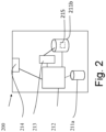
- FIG 2 illustrates an example of a control apparatus 200 for controlling a function of the (R)AN or the 5GC as illustrated on Figure 1 .
- the control apparatus may comprise at least one random access memory (RAM) 211a, at least on read only memory (ROM) 211b, at least one processor 212, 213 and an input/output interface 214.
- the at least one processor 212, 213 may be coupled to the RAM 211a and the ROM 211b.
- the at least one processor 212, 213 may be configured to execute an appropriate software code 215.
- the software code 215 may for example allow to perform one or more steps to perform one or more of the present aspects.
- the software code 215 may be stored in the ROM 211b.
- the control apparatus 200 may be interconnected with another control apparatus 200 controlling another function of the 5G (R)AN or the 5GC.
- each function of the (R)AN or the 5GC comprises a control apparatus 200.
- two or more functions of the (R)AN or the 5GC may share a control apparatus.
- FIG 3 illustrates an example of a terminal 300, such as the terminal illustrated on Figure 1 .
- the terminal 300 may be provided by any device capable of sending and receiving radio signals.
- Non-limiting examples comprise a user equipment, a mobile station (MS) or mobile device such as a mobile phone or what is known as a 'smart phone', a computer provided with a wireless interface card or other wireless interface facility (e.g., USB dongle), a personal data assistant (PDA) or a tablet provided with wireless communication capabilities, a machine-type communications (MTC) device, a Cellular Internet of things (CloT) device or any combinations of these or the like.
- the terminal 300 may provide, for example, communication of data for carrying communications.
- the communications may be one or more of voice, electronic mail (email), text message, multimedia, data, machine data and so on.
- the terminal 300 may receive signals over an air or radio interface 307 via appropriate apparatus for receiving and may transmit signals via appropriate apparatus for transmitting radio signals.
- transceiver apparatus is designated schematically by block 306.
- the transceiver apparatus 306 may be provided for example by means of a radio part and associated antenna arrangement.
- the antenna arrangement may be arranged internally or externally to the mobile device.
- the terminal 300 may be provided with at least one processor 301, at least one memory ROM 302a, at least one RAM 302b and other possible components 303 for use in software and hardware aided execution of tasks it is designed to perform, including control of access to and communications with access systems and other communication devices.
- the at least one processor 301 is coupled to the RAM 302b and the ROM 302a.
- the at least one processor 301 may be configured to execute an appropriate software code 308.
- the software code 308 may for example allow to perform one or more of the present aspects.
- the software code 308 may be stored in the ROM 302a.
- the processor, storage and other relevant control apparatus can be provided on an appropriate circuit board and/or in chipsets. This feature is denoted by reference 304.
- the device may optionally have a user interface such as keypad 305, touch sensitive screen or pad, combinations thereof or the like.
- a user interface such as keypad 305, touch sensitive screen or pad, combinations thereof or the like.
- one or more of a display, a speaker and a microphone may be provided depending on the type of the device.
- One or more aspects of this disclosure relate to techniques for automatically instantiating (i.e. creating) a closed loop (CL) in a communication system.
- the communication may be a mobile system, such as a 5G system or a future generation system.
- a CL may refer to a control theory concept based on the sequence below:
- a CL may be executed once, terminating execution after receiving feedback.
- a CL may be executed multiple times.
- a CL may also be executed a finite number of times or an infinite resulting in what is called an infinite loop.
- a CL may refer to the control theory concept as such or to a logical entity implementing the control theory concept.
- the logical entity may comprise one or more CL components.
- FIG 4 shows a schematic representation of a CL comprising four CL components chained to form a loop (see Stephen S. Mwanje, Christian Mannweiler (2020), "Towards Cognitive Autonomous Networks: Network Management Automation for 5G and Beyond", Wiley ).
- the four CL components may comprise a data collection CL component, an analysis component, a decision component and an execution component. It will be understood that the CL may comprise less than four CL components or more than four components.
- a CL management function may refer to a logical entity that interacts with a network (or network resources) to capture or monitor data about a network event and to act on the network (or the network resources) .
- a CL MnF may comprise a CL and a control point (CP) via which the CL MnF may be managed or controlled (i.e. a point which supports interaction with external entities).
- CP control point
- the CL MnF may provide a control interface through which external entities may manage or control the CL MnF as well as an exposure interface through which the CL MnF may expose characteristics of the CL towards external entities.
- the CP may be implemented as a standalone component within the CL MnF or as part of the CL components specially as part of the decision CL component.
- Figure 5 shows a schematic representation of an MnF Fn1 with a CL comprising four closed loop components (the analysis CL component and the analysis CL component are separate) and a control point and another MnF Fn2 with a CL comprising three closed loop components (the analysis CL component and the analysis CL component are combined).
- a CL is not necessarily based on the above sequence of operations 1) to 5).
- a CL may be based on a different sequence, such as MAPE-K (Monitor, Analyse, Plan, Execute ⁇ Knowledge - see Kephart, J. and D. Chess: "The Vision of Autonomic Computing", IEEE Computer, vol. 36, no. 1, pp. 41-50, DOI 10.1109/MC.2003.1160055, January 2003 ) or OODA (Observe, Orient, Decide, Act - see ETSI GR ZSM 002: "Zero-touch network and Service Management (ZSM); Reference Architecture").
- MAPE-K Monitoring, Analyse, Plan, Execute ⁇ Knowledge - see Kephart, J. and D. Chess: "The Vision of Autonomic Computing", IEEE Computer, vol. 36, no. 1, pp. 41-50, DOI 10.1109/MC.2003.1160055, January 2003
- OODA Observe, Orient, Decide, Act
- CL MnF Fn1 and Fn2 are represented as separate logical entities with separate control interfaces and exposure interfaces this may not always be the case.
- Multiple CL MnFs may be implemented as combinations of different CL components in a single entity (e.g. in a single application) with a single control interface and a single exposure interface.
- An example may be the application Nokia NetACT.
- Nokia NetACT may implement different CL components for data collection such as the simple network management protocol mediation, for analysis such as the monitor, for decision making such as the performance manager as well as for execution of network configurations such as the configurator.
- the CL components may be combined to compose a separate CL MnFs.
- multi-vendor interactions may only be required for the control interface and the exposure interface. That is, Nokia NetACT may interact with external entities from Nokia or from another vendor via the control interface and the exposure interface.
- a CL may be a multi-vendor CL. That is, a CL may be composed from multi-vendor CL components using standardised APIs. However, these APIs are currently not available. As illustrated by Figure 6 , the different CL components implement control interfaces and exposure interfaces, through which an external entity may control the CL components. These control interfaces and exposure interfaces are not yet explored. Each CL component may also implement run-time interfaces through which the CL components may exchange data to accomplish the network management tasks.
- a common implementation may assume that a multi-vendor CL is integrated and managed by a (human) operator manually. However, given the likely large number of CLs that may be instantiated (i.e. created) on a given network, it would be a heavy task for an operator to manage the CLs. Instead another means is needed to automate the management operations. The question then is how to automatically instantiate (i.e. create) multi-vendor CLs while leveraging standardized APIs.
- One or more aspects of this disclosure provide techniques for automatically instantiating a CL in an efficient way. More specifically, one or more aspects of this disclosure provide techniques for automatically instantiating a CL while leverage the 3GPP SA5 APIs.
- One or more aspects of this disclosure shed light on the APIs, which enable different CL components to implement control interfaces and exposure interfaces.
- On or more aspect of this disclosure provide a CL control/controller (CLC) that is responsible for identifying CL components based on an input provided by an operator and instantiating a CL with the CL components.
- the CLC may replaces the operator for identifying CL components and instantiating a CL with the CL components the CL as illustrated on Figure 7 .
- the CLC may be an automation platform or a part of an automation platform.
- the operator may send a request to the CLC to instantiate a CL.
- the request may comprise information (input from the operator) that allows the CLC to identify CL components and instantiate a CL with the CL components .
- the operator may know (e.g. via pre-arrangement per use case, capabilities and/or roles) the exact CL components which need to compose a CL.
- the operator may identify the CL components, for example using their unique identifiers (e.g. unique names such as Calculate_mean or Statistical_analysis).
- the operator may define the roles (e.g. Data collection, Analysis, Decision, execution) of the CL components.
- the operator may provide the unique identifiers and roles in a request sent to the CLC.
- the operator may use a hash function.
- An example of a hash function may be:
- the operator may not know the exact CL components which need to compose a CL. However, the operator may know the inputs (e.g. tuple) to be used by the CL components and/or outputs (e.g. tuple) to be generated by the CL components. In that case, the operator may identify the inputs and/or outputs of the CL components. The operator may define the roles (e.g. Data collection, Analysis, Decision, execution) of the CL components. The operator may provide the inputs and/or outputs of the CL components and the roles of the CL components in a request sent to the CLC. The operator may use a hash function. An example of a has function may be:
- the operator may not know the exact CL components which need to compose a CL. Also, the operator may not know the inputs (e.g. tuple) to be used by the CL components and outputs (e.g. tuple) to be generated by the CL components. However, the operator may know the capabilities (e.g. reading data relating to the performance of a cell from a network database and format the data and/or making a prediction based on formatted data) of the CL components (or a subset of them). In that case, the operator may identify the capabilities of the CL components. The operator may define the roles (e.g. Data collection, Analysis, Decision, execution) of the CL components. The operator may provide the capabilities of the CL components and the roles of the CL in a request sent to the CLC. The operator may use a hash function. An example of a hash function may be:
- the operator may not know the exact CL components which need to compose a CL. However, the operator may know the inputs (e.g. tuple) to be used by the CL components, outputs (e.g. tuple) to be generated by the CL components and/or the capabilities (e.g. reading data relating to the performance of a cell from a network database and format the data and/or making a prediction based on formatted data) of the CL components (or a subset of them). The operator may provide the capabilities of the CL components and the inputs of the CL components as the input in a request sent to the CLC.
- the inputs e.g. tuple
- outputs e.g. tuple
- the capabilities e.g. reading data relating to the performance of a cell from a network database and format the data and/or making a prediction based on formatted data
- the operator may provide the capabilities of the CL components and the outputs of the CL components as the input in a request sent to the CLC.
- the operator may provide the capabilities of the CL components, the inputs and the outputs of the CL components in a request sent to the CLC.
- the operator may use a hash function.
- An example of a hash function may be a combination of the above has functions.
- the operator may trigger the instantiation of the CL for example using the createMOI procedure defined by 3GPP SA5.
- the CLC may identify the CL components to compose the CL based on the unique identifiers of the CL components, inputs and outputs of the CL components, roles of the CL components and/or capabilities of the CL component indicated by the operator in the request.
- the CLC may identify the CL components to compose the CL based on assurance expectations of the CL components or the CL (e.g. expressed in form of a CL goal, which can be decomposed into assurance performance metrics such as delay, throughput, etc).
- the information may be provided using a hash function.
- the CLC may configure the CL components.
- the CLC may configure the relation and data exchange among the CL components.
- the CLC may configure the data collection CL component to deliver data to the analytics CL component.
- the CLC may configure the analytics CL component to collect data from the data collection CL component whenever such data is needed to compute analytics.
- the CLC may configure the analytics CL component to deliver data to the decision CL component.
- the CLC may configure the decision CL component to request and collect data in the form of an analytics report from the analytics CL component whenever such data is needed to derive a decision.
- the CLC may configure the decision CL component to deliver data in form of recommended actions or commands to the execution CL component.
- the CLC may configure the execution CL component to collect data in form of a set of recommended actions from the decision CL component whenever such recommendations are needed.
- the CLC may configure the execution component to implement the recommended actions on to the network once received or upon certain conditions (e.g. threshold surpass).
- the CLC may configure the CL components to provide performance management (PM), key performance indicator (KPI)
- the CLC may be modelled as a logical entity that receives and fulfils the requests to instantiate the CL for example using the createMOI procedure.
- the section below depicts the set of classes that encapsulates the information relevant for this management service (MnS )and provides an overview of the relationships between relevant classes in UML.
- FIG. 8a shows a schematic representation of a CLC network resource management fragment.
- Figure 9 shows a signalling diagram of a first process for instantiating (i.e. creating) a CL for managing a communication system.
- the operator may identify and compile information to be provided to the CLC to identify CLcomponents and instantiate (i.e. create) a CL with the CL components.
- the information may comprise unique identifiers (e.g. unique names) of the CL components, inputs of the CL components, outputs of the CL components, roles of the CL components and/or capabilities of the CL components.
- the information may further comprise assurance expectations of the CL components or the CL (e.g. expressed in form of a CL goal, which can be decomposed into assurance performance metrics such as delay, throughput, etc).
- the information may be provided using a hash function.
- step 1 the operator may send a request to the CLC to instantiate (i.e. create) a CL.
- the request may provide the information that may be used by the CLC to identify CL components and then instantiate the CL.
- the CLC may interpret the information.
- the CLC may determine how the CL components should be identified based on the information. For example, if the information comprises the unique identifiers of the CL components then the CLC may determine that the CL components identified by the unique identifiers should be identified . If the information only comprises inputs and outputs of the CL components then the CLC may determine that CL components matching the inputs and outputs of the CL components provided by the operator should be identified .
- the CLC may identify the CL components based on the information.
- the CLC may identify the CL components based on a repository that holds available CL components.
- the CLC may then compose the CL with the identified CL components.
- the CL components may operate on different systems of the network (e.g. a CL component may operate on a management data analytics platform or function while another CL component may be operate on a cognitive self organizing network server.
- the CLC may identify the systems where the CL components should operate.
- the repository may integrated within the CLC in which case step 2 may be internal within the CLC.
- step 4 the CLC configure the CL component.
- the CLC may configure the relation and data exchange among the CL components.
- the CLC may configure the CL.
- the CLC may activate the CL components.
- the CLC may mark the CL as active.
- the CLC may send a notification to the operator indicating that the CL has been instantiated (i.e. created).
- the CLC may send a notification to the operator indicating that the CL has not been instantiated (i.e. created).
- step 7 the operator may further configure the CL or the CL components.
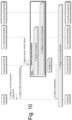
- Figure 10 shows a signalling diagram of a second process for instantiating (i.e creating) a CL for managing a communication system.
- Each CL component may be identified by a unique identifier (e.g. unique name). In a scenario the operator may know the unique identifiers of the CL components.
- the operator may identify and compile information to be provide to the CLC to identify CLC components and instantiate (i.e. create) a CL with the CL components.
- the information may comprise unique identifiers (e.g. unique names) of the CL components and roles of the CL components.
- the information may be provided using a hash function.
- step 1 the operator may send a request to the CLC to instantiate (i.e. create) a CL.
- the request may provide the information that may be used by the CLC to identify CL components and then instantiate the CL.
- the CLC may interpret the information.
- the CLC may determine how the CL components should be identified based on the information.
- the information comprises the unique identifiers of the CL components then the CLC may determine that CL components identified by the unique identifiers provided by the operator should be identified.
- the CLC may identify the CL components based on the information.
- the CLC may identify the CL components based on a repository that holds available CL components and/or based on pre-configuration arrangements.
- the CLC may then compose the CL with the identified CL components.
- the CL components may operate on different systems of the network (e.g. a CL component may operate on a management data analytics platform or function while another CL component may be operate on a cognitive self organizing network server.
- the CLC may identify the systems where the CL components should operate.
- the repository may be integrated within the CLC in which case step 2 may be internal within the CLC.
- step 4 the CLC configure the CL component.
- the CLC may configure the relation and data exchange among the CL components.
- the CLC may configure the CL.
- the CLC may activate the CL components.
- the CLC may mark the CL as active.
- the CLC may send a notification to the operator indicating that the CL has been instantiated (i.e. created).
- the CLC may send a notification to the operator indicating that the CL has not been instantiated (i.e. created).
- step 7 the operator may further configure the CL or the CL components.
- Figure 11 shows a signalling diagram of a third process for instantiating (i.e. creating) a CL for managing a communication system.
- Each CL component may be identified by a unique identifier (e.g. unique name).
- Each CL component may be identified by inputs used by the CL component and/or outputs generated by the CL component. In a scenario the operator may not know the unique identifiers of the CL components but may know the inputs and/or outputs of the CL components.
- a Vendor_x data collection component may use performance management data as inputs and may generate formatted data (e.g. time series) as outputs.
- formatted data e.g. time series
- the CLC may identify the Vendor_x data collection component.
- a Vendor_y analytics and decision component may use formatted data as inputs and may generate decisions as outputs.
- the CLC may identify the Vendor_y analytics and decision component.
- the CLC may be configured to identify CL components matching inputs and/or outputs of the CL components provided by the operator.
- the operator may identify and compile information to be provide to the CLC to identify CLC components and instantiate (i.e. create) a CL with the CL components.
- the information may comprise inputs and/or outputs of the CL components and roles of the CL components.
- the information may be provided using a hash function.
- the inputs and/or outputs of the CL components may be ordered such that the position of the inputs and/or outputs of the CL components is indicative of the role of the CL components.
- the first inputs and/or outputs of a CL component may correspond to a data collection CL component
- the second inputs and/or outputs of a CL component may correspond to an analysis CL component
- the third inputs and/or outputs of a CL component may correspond to a decision CL component
- the fourth inputs and/or outputs of a CL component may correspond to an execution CL component
- step 1 the operator may send a request to the CLC to instantiate (i.e. create) a CL.
- the request may provide the information that may be used by the CLC to identify CL components and then instantiate (i.e. create) the CL.
- the CLC may interpret the information.
- the CLC may determine how the CL components should be identified based on the information.
- the information comprises the inputs and/or outputs of the CL components then the CLC may determine that CL components matching the inputs and outputs of the CL components provided by the operator should be identified.
- the CLC may identify the CL components based on the information.
- the CLC may identify the CL components based on a repository that holds available CL components and/or based on pre-configuration arrangements.
- the CLC may then compose the CL with the identified CL components.
- the CL components may operate on different systems of the network (e.g. a CL component may operate on a management data analytics platform or function while another CL component may be operate on a cognitive self organizing network server.
- the CLC may identify the systems where the CL components should operate.
- the repository may be integrated within the CLC in which case step 2 may be internal within the CLC.
- step 4 the CLC configure the CL component.
- the CLC may configure the relation and data exchange among the CL components.
- the CLC may configure the CL.
- the CLC may activate the CL components.
- the CLC may mark the CL as active.
- the CLC may send a notification to the operator indicating that the CL has been instantiated (i.e. created).
- the CLC may send a notification to the operator indicating that the CL has not been instantiated (i.e. created).
- step 7 the operator may further configure the CL or the CL components.
- Figure 12 shows a signalling diagram of a fourth process for instantiating (i.e. creating) a CL for managing a communication system.
- Each CL component may be identified by a unique identifier (e.g. unique name).
- Each CL component may be identified by inputs used by the CL component and/or outputs generated by the CL component.
- Each CL component may be identified by capabilities of the CL component. In a scenario the operator may not know the unique identifiers of the CL components, the operator may not know the inputs and outputs of the CL components but the operator may know the capabilities of the CL components.
- the capabilities of a data collection CL component may comprise reading the performance of a cell from network databases and providing the PM data formatted into an hourly time series.
- the capabilities of an analytics CL component may comprise using a time series of historical cell performance and providing predictions of the likely performance in the next x hours.
- the value of x may be configurable by the consumer of the analytics.
- the capabilities of the decision CL component may comprise using a particular kind data and format from and making a decision.
- the CLC may be configured to identify CL components matching capabilities of the CL components provided by the operator.
- the operator may identify and compile information to be provide to the CLC to identify CL components and instantiate (i.e. create) a CL with the CL components.
- the information may comprise capabilities of the CL components and/or roles of the CL components.
- the information may be provided using a hash function.
- the capabilities of the CL components may be ordered such that the position of the capabilities of the CL components is indicative of the role of the CL components. For example, the first capabilities of a CL component may correspond to a data collection CL component, the second capabilities of a CL component may correspond to an analysis CL component, the third capabilities of a CL component may correspond to a decision CL component and the fourth capabilities of a CL component may correspond to an execution CL component
- step 1 the operator may send a request to the CLC to instantiate (i.e. create) a CL.
- the request may provide the information that may be used by the CLC to identify CL components and then instantiate (i.e. create) the CL.
- the CLC may interpret the information.
- the CLC may determine how the CL components should be identified based on the information.
- the information comprises the capabilities of the CL components then the CLC may determine that CL components matching the capabilities of the CL components provided by the operator should be identified.
- the CLC may identify the CL components based on the information.
- the CLC may identify the CL components based on a repository that holds available CL components and/or based on pre-configuration arrangements.
- the CLC may then compose the CL with the identified CL components.
- the CL components may operate on different systems of the network (e.g. a CL component may operate on a management data analytics platform or function while another CL component may operate on a cognitive self organizing network server.
- the CLC may identify the systems where the CL components should operate.
- the repository may be integrated within the CLC in which case step 2 may be internal within the CLC.
- step 4 the CLC configure the CL component.
- the CLC may configure the relation and data exchange among the CL components.
- the CLC may configure the CL.
- the CLC may activate the CL components.
- the CLC may mark the CL as active.
- the CLC may send a notification to the operator indicating that the CL has been instantiated (i.e. created).
- the CLC may send a notification to the operator indicating that the CL has not been instantiated (i.e. created).
- step 7 the operator may further configure the CL or the CL components.
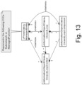
- CL component related information model of Figure 13 may be used.
- the CL component information object class may represent the properties of an abstract CL component.
- the CL component IOC may include attributes inherited from a top IOC (defined in TS 28.622) and one or more of the attributes listed in table 1. The definition of these attributes is provided table 2.
- Table 1 Attribute Name Support Qualifier isReadable isWritable islnvariant isNotifyable CLComponentName M T F T T CLComponentProfile O T F F T CLComponentlnput M T F F T CLComponentOutput M T F F T CLComponentState M T F F T Table 2 Attribute Name Documentation and Allowed Values Properties CLComponentName A user-friendly (and user assignable) name of the input paraemeter.
- the CLComponentProfile of a CL component may comprise descriptions of some or all the characteristics of the CL component, such as descriptions of the roles, descriptions of inputs, descriptions of outputs, descriptions of capabilities, descriptions of data formats, etc.
- the operator may read the CLComponentProfile of a CL component in order to understand the operation of the CL component and how it may be combined with another CL component.
- the entries in the CLComponentProfile may include one or more attributes listed in Table 3 whose definition is provided in Table 4.
- Table 3 Attribute Name Support Qualifier isReadabl e isWritabl e islnvarian t isNotifyabl e CLComponentNam e M T F T T CLComponentDesc ription O T F T T T CLComponentType M T F T T CLComponentOper ations O T F T T T CLComponentlnput Description O T F T T T CLComponentOutp utDescription O T F T T T Table 4 Attribute Name Documentation and Allowed Values Properties CLComponentName A user-friendly (and user assignable) name of the input parameter.
- the requirements for the interfaces of the CL components may be different depending on the characteristics of the CL components, they may be implemented using the same APIs.
- the interfaces for the CL components may comprise a control interface and an exposure interface.
- the control interface may be used to configure the CL components.
- the control interface may be implemented using a provisioning management service produced by the CL components and consumed by the CLC.
- the respective details for each CL component may be implemented as in Table 5.
- Table 5 CL com ponent/ MnS Producer Capability Consumer Data collection Configure data collection characteristics for data CLC - configures the data collection attributes Configure a PM job on the component to deliver PM data to the CLC CLC - configures the PM job on the DC component Configure a data reporting job on the component to deliver data to the analytics component CLC - configures the data reporting job on the DC component
- Analytics Configure behavior characteristics of the analytics operator- configures the Analytics attributes Configure a PM job on the component to deliver PM data to the CLC CLC- configures the PM job on the Analytics com ponent Configure a data reporting job on the component to deliver the analytics report to the decision component CLC- configures the data reporting job on the Analytics component Decision Configure behavior characteristics of the decision making operator- configures the decision attributes Configure relative importance of
- the exposure interface may be used to collect and expose operational data from the CL components to the CLC.
- the exposure interface may be implemented using the file data reporting or streaming data reporting APIs as described in TS 28.532. Therein the service is produced by the CL components and consumed by the CLC.
- the respective details for each CL component may be implemented as in Table 6.
- Figure 14 shows a block diagram of a method for instantiating a CL for managing a communication system performed by a CLC.
- a CLC may receive a request from an operator to instantiate a CL for managing a communication system.
- the CLC may identify CL components based on the request.
- the CLC may instantiate a CL for managing a communication system with the CL components.
- the request may indicate unique identifiers of the CL components.
- the unique identifiers of the CL component may comprise unique names of the CL components.
- the request may indicate roles of the CL components.
- the roles may comprise collecting data, analysing data, making a decision and/or executing a decision.
- the request may indicates capabilities of the CL components.
- the capabilities may comprise reading data relating to a managed object from the object or a network database and format the data and/or making a prediction based on formatted data.
- the request may comprise inputs of the CL components and/or outputs of the CL components.
- the request may comprise performance metrics of the CL components or the CL for managing the communication system.
- Instantiating the CL for managing the communication system with the CL components may comprise: composing the CL for managing the communication system with the CL components; configuring the CL components; configuring the relations between the CL components; and/or configuring the CL for managing the communication system as active
- Configuring the relations between the CL components may comprise connecting the CL components.
- Configuring the CL for managing the communication system may comprise: activating the CL components; and/or marking the CL for managing the communication system as active.
- the CLC may send, to the operator, a notification indicating that the CL for managing the communication system has been instantiated.
- the CLC may send, to the operator, a notification indicating that the CL for managing the communication system has not been instantiated.
- Identifying the CL components is further based on a repository storing identifiers of CL components, roles of the CL components, capabilities of the CL components, inputs of the CL components, outputs of the CL components and/or performance metrics of the CL components.
- the CL components may originate from different vendors.
- the CL components may operate on different systems of the network.
- the CLC may be an automation platform or may be part of an automation platform.
- Figure 15 shows a schematic representation of non-volatile memory media 1500 storing instructions and/or parameters which when executed by a processor allow the processor to perform one or more of the steps of the method of Figure 14 .
- some embodiments may be implemented in hardware or special purpose circuits, software, logic or any combination thereof.
- some aspects may be implemented in hardware, while other aspects may be implemented in firmware or software which may be executed by a controller, microprocessor or other computing device, although embodiments are not limited thereto.
- firmware or software which may be executed by a controller, microprocessor or other computing device, although embodiments are not limited thereto. While various embodiments may be illustrated and described as block diagrams, flow charts, or using some other pictorial representation, it is well understood that these blocks, apparatus, systems, techniques or methods described herein may be implemented in, as non-limiting examples, hardware, software, firmware, special purpose circuits or logic, general purpose hardware or controller or other computing devices, or some combination thereof.
- the embodiments may be implemented by computer software stored in a memory and executable by at least one data processor of the involved entities or by hardware, or by a combination of software and hardware. Further in this regard it should be noted that any procedures, e.g., as in Figure 14 , may represent program steps, or interconnected logic circuits, blocks and functions, or a combination of program steps and logic circuits, blocks and functions.
- the software may be stored on such physical media as memory chips, or memory blocks implemented within the processor, magnetic media such as hard disk or floppy disks, and optical media such as for example DVD and the data variants thereof, CD.
- the memory may be of any type suitable to the local technical environment and may be implemented using any suitable data storage technology, such as semiconductor-based memory devices, magnetic memory devices and systems, optical memory devices and systems, fixed memory and removable memory.
- the data processors may be of any type suitable to the local technical environment, and may include one or more of general purpose computers, special purpose computers, microprocessors, digital signal processors (DSPs), application specific integrated circuits (ASIC), gate level circuits and processors based on multi-core processor architecture, as non-limiting examples.
- circuitry may be configured to perform one or more of the functions and/or method steps previously described. That circuitry may be provided in the base station and/or in the communications device.
- circuitry may refer to one or more or all of the following:
- circuitry also covers an implementation of merely a hardware circuit or processor (or multiple processors) or portion of a hardware circuit or processor and its (or their) accompanying software and/or firmware.
- circuitry also covers, for example integrated device.
Landscapes
- Engineering & Computer Science (AREA)
- Computer Networks & Wireless Communication (AREA)
- Signal Processing (AREA)
- Computer And Data Communications (AREA)
Abstract
Description
- The present disclosure relates to an apparatus, a method, and a computer program for instantiating (i.e. creating) a closed loop for managing a communication system.
- A communication system can be seen as a facility that enables communication sessions between two or more entities such as communication devices, base stations and/or other nodes by providing carriers between the various entities involved in the communications path.
- The communication system may be a wireless communication system. Examples of wireless systems comprise public land mobile networks (PLMN) operating based on radio standards such as those provided by 3GPP, satellite based communication systems and different wireless local networks, for example wireless local area networks (WLAN). The wireless systems can typically be divided into cells, and are therefore often referred to as cellular systems.
- The communication system and associated devices typically operate in accordance with a given standard or specification which sets out what the various entities associated with the system are permitted to do and how that should be achieved. Communication protocols and/or parameters which shall be used for the connection are also typically defined. Examples of standard are the so-called 5G standards.
- According to an aspect there is provided an apparatus comprising means for: receiving a request from an operator to instantiate a closed loop for managing a communication system; identifying closed loop components based on the request; and instantiating a closed loop for managing a communication system with the closed looped components.
- The request may indicate unique identifiers of the closed loop components.
- The unique identifiers of the closed loop component may comprise unique names of the closed loop components.
- The request may indicate roles of the closed loop components.
- The roles may comprise collecting data, analysing data, making a decision and/or executing a decision.
- The request may indicates capabilities of the closed loop components.
- The capabilities may comprise reading data relating to a managed object from the object or a network database and format the data and/or making a prediction based on formatted data.
- The request may comprise inputs of the closed loop components and/or outputs of the closed loop components.
- The request may comprise performance metrics of the closed loop components or the closed loop for managing the communication system.
- Instantiating the closed loop for managing the communication system with the closed loop components may comprise: composing the closed loop for managing the communication system with the closed loop components; configuring the closed loop components; configuring the relations between the closed loop components; and/or configuring the closed loop for managing the communication system as active.
- Configuring the relations between the closed loop components may comprise connecting the closed loop components.
- Configuring the closed loop for managing the communication system may comprise: activating the closed loop components; and/or marking the closed loop for managing the communication system as active.
- The apparatus may comprise means for: sending, to the operator, a notification indicating that the closed loop for managing the communication system has been instantiated; or sending, to the operator, a notification indicating that the closed loop for managing the communication system has not been instantiated.
- Identifying the closed looped components is further based on a repository storing identifiers of closed looped components, roles of the closed loop components, capabilities of the closed loop components, inputs of the closed loop components, outputs of the closed loop components and/or performance metrics of the closed loop components.
- The closed loop components may originate from different vendors.
- The closed loop components may operate on different systems of the network.
- The apparatus may be a closed loop control.
- The closed loop control may be an automation platform or may be part of an automation platform.
- According to an aspect there is provided an apparatus comprising at least one processor and at least one memory including computer code for one or more programs, the at least one memory and the computer code configured, with the at least one processor, to cause the apparatus at least to: receive a request from an operator to instantiate a closed loop for managing a communication system; identify closed loop components based on the request; and instantiate a closed loop for managing a communication system with the closed looped components.
- The request may indicate unique identifiers of the closed loop components.
- The unique identifiers of the closed loop component may comprise unique names of the closed loop components.
- The request may indicate roles of the closed loop components.
- The roles may comprise collecting data, analysing data, making a decision and/or executing a decision.
- The request may indicates capabilities of the closed loop components.
- The capabilities may comprise reading data relating to a managed object from the object or a network database and format the data and/or making a prediction based on formatted data.
- The request may comprise inputs of the closed loop components and/or outputs of the closed loop components.
- The request may comprise performance metrics of the closed loop components or the closed loop for managing the communication system.
- Instantiating the closed loop for managing the communication system with the closed loop components may comprise: composing the closed loop for managing the communication system with the closed loop components; configuring the closed loop components; configuring the relations between the closed loop components; and/or configuring the closed loop for managing the communication system as active.
- Configuring the relations between the closed loop components may comprise connecting the closed loop components.
- Configuring the closed loop for managing the communication system may comprise: activating the closed loop components; and/or marking the closed loop for managing the communication system as active.
- The at least one memory and the computer code may be configured, with the at least one processor, to cause the apparatus at least to: send, to the operator, a notification indicating that the closed loop for managing the communication system has been instantiated; or send, to the operator, a notification indicating that the closed loop for managing the communication system has not been instantiated.
- Identifying the closed looped components is further based on a repository storing identifiers of closed looped components, roles of the closed loop components, capabilities of the closed loop components, inputs of the closed loop components, outputs of the closed loop components and/or performance metrics of the closed loop components.
- The closed loop components may originate from different vendors.
- The closed loop components may operate on different systems of the network.
- The apparatus may be a closed loop control.
- The closed loop controller may be an automation platform or may be part of an automation platform.
- According to an aspect there is provided an apparatus comprising circuitry configured to: receive a request from an operator to instantiate a closed loop for managing a communication system; identify closed loop components based on the request; and instantiate a closed loop for managing a communication system with the closed looped components.
- The request may indicate unique identifiers of the closed loop components.
- The unique identifiers of the closed loop component may comprise unique names of the closed loop components.
- The request may indicate roles of the closed loop components.
- The roles may comprise collecting data, analysing data, making a decision and/or executing a decision.
- The request may indicates capabilities of the closed loop components.
- The capabilities may comprise reading data relating to a managed object from the object or a network database and format the data and/or making a prediction based on formatted data.
- The request may comprise inputs of the closed loop components and/or outputs of the closed loop components.
- The request may comprise performance metrics of the closed loop components or the closed loop for managing the communication system.
- Instantiating the closed loop for managing the communication system with the closed loop components may comprise: composing the closed loop for managing the communication system with the closed loop components; configuring the closed loop components; configuring the relations between the closed loop components; and/or configuring the closed loop for managing the communication system as active.
- Configuring the relations between the closed loop components may comprise connecting the closed loop components.
- Configuring the closed loop for managing the communication system may comprise: activating the closed loop components; and/or marking the closed loop for managing the communication system as active.
- The apparatus may comprise circuitry configured to: send, to the operator, a notification indicating that the closed loop for managing the communication system has been instantiated; or send, to the operator, a notification indicating that the closed loop for managing the communication system has not been instantiated.
- Identifying the closed looped components is further based on a repository storing identifiers of closed looped components, roles of the closed loop components, capabilities of the closed loop components, inputs of the closed loop components, outputs of the closed loop components and/or performance metrics of the closed loop components.
- The closed loop components may originate from different vendors.
- The closed loop components may operate on different systems of the network.
- The apparatus may be a closed loop control.
- The closed loop controller may be an automation platform or may be part of an automation platform.
- According to an aspect there is provided a method comprising: receiving a request from an operator to instantiate a closed loop for managing a communication system; identifying closed loop components based on the request; and instantiating a closed loop for managing a communication system with the closed looped components.
- The request may indicate unique identifiers of the closed loop components.
- The unique identifiers of the closed loop component may comprise unique names of the closed loop components.
- The request may indicate roles of the closed loop components.
- The roles may comprise collecting data, analysing data, making a decision and/or executing a decision.
- The request may indicates capabilities of the closed loop components.
- The capabilities may comprise reading data relating to a managed object from the object or a network database and format the data and/or making a prediction based on formatted data.
- The request may comprise inputs of the closed loop components and/or outputs of the closed loop components.
- The request may comprise performance metrics of the closed loop components or the closed loop for managing the communication system.
- Instantiating the closed loop for managing the communication system with the closed loop components may comprise: composing the closed loop for managing the communication system with the closed loop components; configuring the closed loop components; configuring the relations between the closed loop components; and/or configuring the closed loop for managing the communication system as active.
- Configuring the relations between the closed loop components may comprise connecting the closed loop components.
- Configuring the closed loop for managing the communication system may comprise: activating the closed loop components; and/or marking the closed loop for managing the communication system as active.
- The method may comrpise: sending, to the operator, a notification indicating that the closed loop for managing the communication system has been instantiated; or sending, to the operator, a notification indicating that the closed loop for managing the communication system has not been instantiated.
- Identifying the closed looped components is further based on a repository storing identifiers of closed looped components, roles of the closed loop components, capabilities of the closed loop components, inputs of the closed loop components, outputs of the closed loop components and/or performance metrics of the closed loop components.
- The closed loop components may originate from different vendors.
- The closed loop components may operate on different systems of the network.
- The method may be performed by a closed loop control.
- The closed loop control may be an automation platform or may be part of an automation platform.
- According to an aspect there is provided a computer program comprising computer executable code which when run on at least one processor is configured to: receive a request from an operator to instantiate a closed loop for managing a communication system; identify closed loop components based on the request; and instantiate a closed loop for managing a communication system with the closed looped components.
- The request may indicate unique identifiers of the closed loop components.
- The unique identifiers of the closed loop component may comprise unique names of the closed loop components.
- The request may indicate roles of the closed loop components.
- The roles may comprise collecting data, analysing data, making a decision and/or executing a decision.
- The request may indicates capabilities of the closed loop components.
- The capabilities may comprise reading data relating to a managed object from the object or a network database and format the data and/or making a prediction based on formatted data.
- The request may comprise inputs of the closed loop components and/or outputs of the closed loop components.
- The request may comprise performance metrics of the closed loop components or the closed loop for managing the communication system.
- Instantiating the closed loop for managing the communication system with the closed loop components may comprise: composing the closed loop for managing the communication system with the closed loop components; configuring the closed loop components; configuring the relations between the closed loop components; and/or configuring the closed loop for managing the communication system as active.
- Configuring the relations between the closed loop components may comprise connecting the closed loop components.
- Configuring the closed loop for managing the communication system may comprise: activating the closed loop components; and/or marking the closed loop for managing the communication system as active.
- The computer program may comprise computer executable code which when run on at least one processor is configured to: send, to the operator, a notification indicating that the closed loop for managing the communication system has been instantiated; or send, to the operator, a notification indicating that the closed loop for managing the communication system has not been instantiated.
- Identifying the closed looped components is further based on a repository storing identifiers of closed looped components, roles of the closed loop components, capabilities of the closed loop components, inputs of the closed loop components, outputs of the closed loop components and/or performance metrics of the closed loop components.
- The closed loop components may originate from different vendors.
- The closed loop components may operate on different systems of the network.
- The at least one processor may be part of a closed loop control.
- The closed loop controller may be an automation platform or may be part of an automation platform.
- According to an aspect, there is provided a computer readable medium comprising program instructions stored thereon for performing at least one of the above methods.
- According to an aspect, there is provided a non-transitory computer readable medium comprising program instructions stored thereon for performing at least one of the above methods.
- According to an aspect, there is provided a non-volatile tangible memory medium comprising program instructions stored thereon for performing at least one of the above methods.
- In the above, many different aspects have been described. It should be appreciated that further aspects may be provided by the combination of any two or more of the aspects described above.
- Various other aspects are also described in the following detailed description and in the attached claims.
-
- AF:
- Application Function
- AMF:
- Access and Mobility Management Function
- API:
- Application Programming Interface
- BS:
- Base Station
- CL:
- Closed Loop
- CLC:
- Closed Loop Control/Controller
- CP:
- Control Point
- CU:
- Centralized Unit
- DL:
- Downlink
- DU:
- Distributed Unit
- gNB:
- gNodeB
- F:
- False
- GSM:
- Global System for Mobile communication
- HSS:
- Home Subscriber Server
- IOC:
- Information Object Class
- loT:
- Internet of Things
- KPI:
- Key Performance Indicator
- LTE:
- Long Term Evolution
- M:
- Mandatory
- MAC:
- Medium Access Control
- MnF :
- Management Function
- MnS :
- Management Service
- MS:
- Mobile Station
- MTC:
- Machine Type Communication
- NEF:
- Network Exposure Function
- NF:
- Network Function
- NR:
- New radio
- NRF:
- Network Repository Function
- O:
- Optional
- PDU:
- Packet Data Unit
- PM:
- Performance Management
- RAM:
- Random Access Memory
- (R)AN:
- (Radio) Access Network
- ROM:
- Read Only Memory
- SDK:
- Software Development Kit
- SMF:
- Session Management Function
- T:
- True
- TR:
- Technical Report
- TS:
- Technical Specification
- UE:
- User Equipment
- UMTS:
- Universal Mobile Telecommunication System
- 3GPP:
- 3rd Generation Partnership Project
- 5G:
- 5th Generation
- 5GC:
- 5G Core network
- 5GS:
- 5G System
- Embodiments will now be described, by way of example only, with reference to the accompanying Figures in which:
-
Figure 1 shows a schematic representation of a 5G system; -
Figure 2 shows a schematic representation of a control apparatus; -
Figure 3 shows a schematic representation of a terminal; -
Figure 4 shows a schematic representation of a closed loop comprising four closed loop components; -
Figure 5 shows a schematic representation of a closed loop management function with a closed loop comprising four closed loop components and a control point and another closed loop management function with a closed loop comprising three closed loop components and a control point; -
Figure 6 shows a schematic representation of a manually integrated and managed multi-vendor closed loop (i.e. closed loop comprising closed loop component originating from multiple vendors); -
Figure 7 shows a schematic representation of an automatically integrated and managed multi-vendor closed loop (i.e. closed loop comprising closed loop component originating from multiple vendors); - Each of
figures 8a and 8b shows a schematic representation of a closed loop control network resource management fragment; -
Figure 9 shows a signalling diagram of a first process for instantiating (i.e. creating) a closed loop for managing a communication system; -
Figure 10 shows a signalling diagram of a second process for instantiating (i.e. creating) a closed loop for managing a communication system; -
Figure 11 shows a signalling diagram of a third process for instantiating (i.e. creating) a closed loop for managing a communication system; -
Figure 12 shows a signalling diagram of a fourth process for instantiating (i.e. creating) a closed loop for managing a communication system; -
Figure 13 shows a schematic representation of a closed loop control network resource management fragment; -
Figure 14 shows a block diagram of a method for instantiating (i.e. creating) a closed loop for managing a communication system performed by a closed loop control; and -
Figure 15 shows a schematic representation of a non-volatile memory medium storing instructions which when executed by a processor allow a processor to perform one or more of the steps of the method ofFigure 14 . - In the following certain embodiments are explained with reference to mobile communication devices capable of communication via a wireless cellular system and mobile communication systems serving such mobile communication devices. Before explaining in detail the exemplifying embodiments, certain general principles of a wireless communication system, access systems thereof, and mobile communication devices are briefly explained with reference to
Figures 1 ,2 and3 to assist in understanding the technology underlying the described examples. -
Figure 1 shows a schematic representation of a 5G system (5GS). The 5GS may comprises a terminal, a (radio) access network ((R)AN), a 5G core network (5GC), one or more application functions (AF) and one or more data networks (DN). - The 5G (R)AN may comprise one or more gNodeB (gNB) distributed unit functions connected to one or more gNodeB (gNB) centralized unit functions.
- The 5GC may comprise an access and mobility management function (AMF), a session management function (SMF), an authentication server function (AUSF), a user data management (UDM), a user plane function (UPF) and/or a network exposure function (NEF). The 5GC may comprise other network functions (NF) non-illustrated such as an automation platform implementing a control loop controller (CLC).
-
Figure 2 illustrates an example of acontrol apparatus 200 for controlling a function of the (R)AN or the 5GC as illustrated onFigure 1 . The control apparatus may comprise at least one random access memory (RAM) 211a, at least on read only memory (ROM) 211b, at least oneprocessor output interface 214. The at least oneprocessor RAM 211a and theROM 211b. The at least oneprocessor appropriate software code 215. Thesoftware code 215 may for example allow to perform one or more steps to perform one or more of the present aspects. Thesoftware code 215 may be stored in theROM 211b. Thecontrol apparatus 200 may be interconnected with anothercontrol apparatus 200 controlling another function of the 5G (R)AN or the 5GC. In some embodiments, each function of the (R)AN or the 5GC comprises acontrol apparatus 200. In alternative embodiments, two or more functions of the (R)AN or the 5GC may share a control apparatus. -
Figure 3 illustrates an example of a terminal 300, such as the terminal illustrated onFigure 1 . The terminal 300 may be provided by any device capable of sending and receiving radio signals. Non-limiting examples comprise a user equipment, a mobile station (MS) or mobile device such as a mobile phone or what is known as a 'smart phone', a computer provided with a wireless interface card or other wireless interface facility (e.g., USB dongle), a personal data assistant (PDA) or a tablet provided with wireless communication capabilities, a machine-type communications (MTC) device, a Cellular Internet of things (CloT) device or any combinations of these or the like. The terminal 300 may provide, for example, communication of data for carrying communications. The communications may be one or more of voice, electronic mail (email), text message, multimedia, data, machine data and so on. - The terminal 300 may receive signals over an air or
radio interface 307 via appropriate apparatus for receiving and may transmit signals via appropriate apparatus for transmitting radio signals. InFigure 3 transceiver apparatus is designated schematically byblock 306. Thetransceiver apparatus 306 may be provided for example by means of a radio part and associated antenna arrangement. The antenna arrangement may be arranged internally or externally to the mobile device. - The terminal 300 may be provided with at least one
processor 301, at least onememory ROM 302a, at least oneRAM 302b and otherpossible components 303 for use in software and hardware aided execution of tasks it is designed to perform, including control of access to and communications with access systems and other communication devices. The at least oneprocessor 301 is coupled to theRAM 302b and theROM 302a. The at least oneprocessor 301 may be configured to execute anappropriate software code 308. Thesoftware code 308 may for example allow to perform one or more of the present aspects. Thesoftware code 308 may be stored in theROM 302a. - The processor, storage and other relevant control apparatus can be provided on an appropriate circuit board and/or in chipsets. This feature is denoted by
reference 304. The device may optionally have a user interface such askeypad 305, touch sensitive screen or pad, combinations thereof or the like. Optionally one or more of a display, a speaker and a microphone may be provided depending on the type of the device. - One or more aspects of this disclosure relate to techniques for automatically instantiating (i.e. creating) a closed loop (CL) in a communication system. The communication may be a mobile system, such as a 5G system or a future generation system.
- A CL may refer to a control theory concept based on the sequence below:
- 1) observe an event from an underlying process or system,
- 2) interpret and analyze the event to create an insight,
- 3) decide, select or recommend an action based on the insight,
- 4) execute the action onto the underlying process or system and
- 5) receive feedback on the effect of the action on the process or system.
- A CL may be executed once, terminating execution after receiving feedback. A CL may be executed multiple times. A CL may also be executed a finite number of times or an infinite resulting in what is called an infinite loop.
- A CL may refer to the control theory concept as such or to a logical entity implementing the control theory concept. The logical entity may comprise one or more CL components.
-
Figure 4 shows a schematic representation of a CL comprising four CL components chained to form a loop (see Stephen S. Mwanje, Christian Mannweiler (2020), "Towards Cognitive Autonomous Networks: Network Management Automation for 5G and Beyond", Wiley). The four CL components may comprise a data collection CL component, an analysis component, a decision component and an execution component. It will be understood that the CL may comprise less than four CL components or more than four components. - A CL management function (MnF) may refer to a logical entity that interacts with a network (or network resources) to capture or monitor data about a network event and to act on the network (or the network resources) .
- A CL MnF may comprise a CL and a control point (CP) via which the CL MnF may be managed or controlled (i.e. a point which supports interaction with external entities).
- The CL MnF may provide a control interface through which external entities may manage or control the CL MnF as well as an exposure interface through which the CL MnF may expose characteristics of the CL towards external entities. Note that the CP may be implemented as a standalone component within the CL MnF or as part of the CL components specially as part of the decision CL component.
-
Figure 5 shows a schematic representation of an MnF Fn1 with a CL comprising four closed loop components (the analysis CL component and the analysis CL component are separate) and a control point and another MnF Fn2 with a CL comprising three closed loop components (the analysis CL component and the analysis CL component are combined). - It is important to note that a CL is not necessarily based on the above sequence of operations 1) to 5). A CL may be based on a different sequence, such as MAPE-K (Monitor, Analyse, Plan, Execute ― Knowledge - see Kephart, J. and D. Chess: "The Vision of Autonomic Computing", IEEE Computer, vol. 36, no. 1, pp. 41-50, DOI 10.1109/MC.2003.1160055, January 2003) or OODA (Observe, Orient, Decide, Act - see ETSI GR ZSM 002: "Zero-touch network and Service Management (ZSM); Reference Architecture").
- Although on
Figure 5 the CL MnF Fn1 and Fn2 are represented as separate logical entities with separate control interfaces and exposure interfaces this may not always be the case. Multiple CL MnFs may be implemented as combinations of different CL components in a single entity (e.g. in a single application) with a single control interface and a single exposure interface. - An example may be the application Nokia NetACT. Nokia NetACT may implement different CL components for data collection such as the simple network management protocol mediation, for analysis such as the monitor, for decision making such as the performance manager as well as for execution of network configurations such as the configurator. The CL components may be combined to compose a separate CL MnFs. With Nokia NetACT multi-vendor interactions may only be required for the control interface and the exposure interface. That is, Nokia NetACT may interact with external entities from Nokia or from another vendor via the control interface and the exposure interface.
- There is a push however for multi-vendor network automation environments. For example, Nokia EdenNet seeks to support third party applications by providing a software development kit (the EdenNet SDK) through which third-party vendors may develop modules that can be executed on EdenNet. This supports specific modules for accomplishing certain tasks, for example providing a specific customized analysis on some indicated data. It however requires close integration, for example the third-party vendor shall co-develop the application using EdenNet SDK. Yet because of intellectual property concerns, the vendors may not be willing to open their developments by using a common development kit. Instead, the eventual implementation is likely to be a platform through which multi-vendor CLs are integrated without the need for a shared development.
- A CL may be a multi-vendor CL. That is, a CL may be composed from multi-vendor CL components using standardised APIs. However, these APIs are currently not available. As illustrated by
Figure 6 , the different CL components implement control interfaces and exposure interfaces, through which an external entity may control the CL components. These control interfaces and exposure interfaces are not yet explored. Each CL component may also implement run-time interfaces through which the CL components may exchange data to accomplish the network management tasks. - Typically, a common implementation may assume that a multi-vendor CL is integrated and managed by a (human) operator manually. However, given the likely large number of CLs that may be instantiated (i.e. created) on a given network, it would be a heavy task for an operator to manage the CLs. Instead another means is needed to automate the management operations. The question then is how to automatically instantiate (i.e. create) multi-vendor CLs while leveraging standardized APIs.
- One or more aspects of this disclosure provide techniques for automatically instantiating a CL in an efficient way. More specifically, one or more aspects of this disclosure provide techniques for automatically instantiating a CL while leverage the 3GPP SA5 APIs.
- One or more aspects of this disclosure shed light on the APIs, which enable different CL components to implement control interfaces and exposure interfaces.
- There has been discussions in standards groups for whitebox deployments, where CL components are not pre-integrated or pre-selected and combined by the respective vendors, but where CL can be instantiated (i.e. created) by combining CL components from different vendors. However, no mechanism has been provided to achieve this.
- On or more aspect of this disclosure provide a CL control/controller (CLC) that is responsible for identifying CL components based on an input provided by an operator and instantiating a CL with the CL components. The CLC may replaces the operator for identifying CL components and instantiating a CL with the CL components the CL as illustrated on
Figure 7 . - The CLC may be an automation platform or a part of an automation platform.
- The operator may send a request to the CLC to instantiate a CL. The request may comprise information (input from the operator) that allows the CLC to identify CL components and instantiate a CL with the CL components . There may be four possible methods that may be used by the CLC to identify the CL components.
- In a first method using CL components identifiers, the operator may know (e.g. via pre-arrangement per use case, capabilities and/or roles) the exact CL components which need to compose a CL. In that case, the operator may identify the CL components, for example using their unique identifiers (e.g. unique names such as Calculate_mean or Statistical_analysis). The operator may define the roles (e.g. Data collection, Analysis, Decision, execution) of the CL components. The operator may provide the unique identifiers and roles in a request sent to the CLC. The operator may use a hash function. An example of a hash function may be:
       {Data collection - function ABC,
              Analysis - function AXC,
              Decision - function GBC,
       }Execution - function XDF
 {Data collection - cell identifiers,
       Analysis - handover measurements counters data,
       Decision - handover failure statistics,
 }Execution - radio resource control configurations
 {Data collection - capability: collects and formats handover performance data as
       a time series,
       Analysis - capability: derives insight about the state of handover performance
       and possible suggest recommendations,
       Decision - capability: derives actions intended to improve handover for a given
       object (cell or group of cells),
       Execution - capability: implements actions related to cell handover performance
 }e.g. on TTT and CIO
| Attribute Name | Support Qualifier | isReadable | isWritable | islnvariant | isNotifyable |
| CLComponentName | M | T | F | T | T |
| CLComponentProfile | O | T | F | F | T |
| CLComponentlnput | M | T | F | F | T |
| CLComponentOutput | M | T | F | F | T |
| CLComponentState | M | T | F | F | T |
| Attribute Name | Documentation and Allowed Values | Properties |
| CLComponentName | A user-friendly (and user assignable) name of the input paraemeter. | type: String multiplicity: 1 |
| isOrdered: False isUnique: False | ||
| defaultValue: | ||
| allowedValues: Not Applicable | None isNullable: False | |
| CLComponentProfile | It describes the task aspect of the intent that shall be accomplished. | type: String multiplicity: 1 |
| isOrdered: False | ||
| isUnique: False | ||
| defaultValue: | ||
| allowedValues: Not Applicable | None isNullable: False | |
| CLComponentlnputs | It describes the inputs to the CLComponent, as an array for which each entry is one input | type: Object multiplicity: 1 |
| isOrdered: False | ||
| isUnique: False | ||
| defaultValue: None | ||
| allowedValues: Not Applicable | isNullable: False | |
| CLComponentOutputs | It describes the outputs of the CLComponent, as an array for which each entry is one output | type: Object multiplicity: 1 |
| isOrdered: False | ||
| isUnique: False | ||
| defaultValue: None | ||
| allowedValues: Not Applicable | isNullable: False | |
| CLComponentState | It describes the administrative state of the CL component. allowedValues: "Active", "Inactive", | type: ENUM multiplicity: 1 |
| isOrdered: F | ||
| isUnique: F | ||
| defaultValue: None | ||
| isNullable: False |
| Attribute Name | Support Qualifier | isReadabl e | isWritabl e | islnvarian t | isNotifyabl e | |
| CLComponentNam e | M | T | F | T | T | |
| CLComponentDesc ription | O | T | F | T | T | |
| CLComponentType | M | T | F | T | T | |
| CLComponentOper ations | O | T | F | T | T | |
| CLComponentlnput Description | O | T | F | T | T | |
| CLComponentOutp utDescription | O | T | F | T | T | |
| Attribute Name | Documentation and Allowed Values | Properties |
| CLComponentName | A user-friendly (and user assignable) name of the input parameter. | type: String |
| multiplicity: 1 | ||
| isOrdered: False | ||
| isUnique: False | ||
| allowedValues: Not Applicable | defaultValue: None | |
| isNullable: False | ||
| CLComponentDescription | It holds a description of the CLComponent | type: String |
| multiplicity: 1 | ||
| isOrdered: False | ||
| isUnique: False | ||
| allowedValues: Not Applicable | defaultValue: None isNullable: False | |
| CLComponentType | It describes the type of capabilities supported by the CLComponent | type: String |
| multiplicity: 1 | ||
| isOrdered: False | ||
| allowedValues: Not Applicable | isUnique: False | |
| defaultValue: None | ||
| isNullable: False | ||
| CLComponentOperations | It holds a description of kinds of operations undertaken by the CLComponent | type: String |
| multiplicity: 1 | ||
| isOrdered: False | ||
| allowedValues: Not Applicable | isUnique: False | |
| defaultValue: None | ||
| isNullable: False | ||
| CLComponentlnputsDescription | It holds a description of the inputs to the CLComponent, | type: Object |
| multiplicity: 1 | ||
| isOrdered: False | ||
| allowedValues: Not Applicable | isUnique: False | |
| defaultValue: None | ||
| isNullable: False | ||
| CLComponentOutputsDescription | It holds a description of the outputs of the CLComponent, | type: Object |
| multiplicity: 1 | ||
| isOrdered: False | ||
| allowedValues: Not Applicable | isUnique: False | |
| defaultValue: None | ||
| isNullable: False |
| CL com ponent/ MnS Producer | Capability | Consumer |
| Data collection | Configure data collection characteristics for data | CLC - configures the data collection attributes |
| Configure a PM job on the component to deliver PM data to the CLC | CLC - configures the PM job on the DC component | |
| Configure a data reporting job on the component to deliver data to the analytics component | CLC - configures the data reporting job on the DC component | |
| Analytics | Configure behavior characteristics of the analytics | operator- configures the Analytics attributes |
| Configure a PM job on the component to deliver PM data to the CLC | CLC- configures the PM job on the Analytics com ponent | |
| Configure a data reporting job on the component to deliver the analytics report to the decision component | CLC- configures the data reporting job on the Analytics component | |
| Decision | Configure behavior characteristics of the decision making | operator- configures the decision attributes |
| Configure relative importance of different decisions or goals | Operator may configure the decision attributes | |
| Configure a PM job on the component to deliver PM data to the CLC | CLC- configures the PM job on the decision com ponent | |
| Configure a data reporting job on the component to deliver recommended actions to the Execution component | CLC- configures the data reporting job on the decision component | |
| Execution | Configure behavior characteristics of the execution | operator- configures the execution attributes |
| Configure a PM job on the component to deliver PM data to the CLC | CLC- configures the PM job on the execution com ponent | |
| Configure the component to implement provisioning management to execute actions on the network | CLC- configures the data collection job on the execution component |
| CL Com ponent | Capability | Producer | Consumer |
| Data collection | Provide information to the CLC about the status and performance of data collection jobs | Data Collection Component emits the report | CLC |
| Analytics | Provide information to the CLC about the status and performance of analytics jobs or processes | Analytics Component emits the report | CLC |
| Decision | Provide information to the CLC about the performance of data collection jobs | Decision Component emits the report | CLC |
| Execution | Provide information to the CLC about the status of execution jobs towards the resources | Execution Component-emits the report | CLC |
- (a) hardware-only circuit implementations (such as implementations in only analogue and/or digital circuitry);
- (b) combinations of hardware circuits and software, such as:
- (i) a combination of analogue and/or digital hardware circuit(s) with software/firmware and
- (ii) any portions of hardware processor(s) with software (including digital signal processor(s)), software, and memory(ies) that work together to cause an apparatus, such as the communications device or base station to perform the various functions previously described; and
- (c) hardware circuit(s) and or processor(s), such as a microprocessor(s) or a portion of a microprocessor(s), that requires software (e.g., firmware) for operation, but the software may not be present when it is not needed for operation.
Claims (15)
- An apparatus comprising means for:receiving a request from an operator to instantiate a closed loop for managing a communication system;identifying closed loop components based on the request; andinstantiating a closed loop for managing a communication system with the closed looped components.
- The apparatus of claim 1, wherein the request indicates unique identifiers of the closed loop components.
- The apparatus of claim 1 or claim 2, wherein the request indicates roles of the closed loop components.
- The apparatus of claim 3, wherein the roles comprise collecting data, analysing data, making a decision and/or executing a decision.
- The apparatus of any of claims 1 to 4, wherein the request indicates capabilities of the closed loop components.
- The apparatus of claim 5, wherein the capabilities comprise reading data relating to a managed object from the object or a network database and format the data and/or making a prediction based on formatted data.
- The apparatus of any of claims 1 to 6, wherein the request comprises inputs of the closed loop components and/or outputs of the closed loop components.
- The apparatus of any of claims 1 to 7, wherein the request comprises performance metrics of the closed loop components or the closed loop for managing the communication system.
- The apparatus of any of claims 1 to 8, wherein instantiating the closed loop for managing the communication system with the closed loop components comprises:composing the closed loop for managing the communication system with the closed loop components;configuring the closed loop components;configuring the relations between the closed loop components; and/orconfiguring the closed loop for managing the communication system as active
- The apparatus of any of claims 1 to 9, comprising means for:sending, to the operator, a notification indicating that the closed loop for managing the communication system has been instantiated; orsending, to the operator, a notification indicating that the closed loop for managing the communication system has not been instantiated.
- The apparatus of any of claims 1 to 10, wherein identifying the closed looped components is further based on a repository storing identifiers of closed looped components, roles of the closed loop components, capabilities of the closed loop components, inputs of the closed loop components, outputs of the closed loop components and/or performance metrics of the closed loop components.
- The apparatus of any of claims 1 to 11, wherein the closed loop components originate from different vendors.
- The apparatus of any of claims 1 to 12, wherein the apparatus is a closed loop control.
- A method comprising:
receiving a request from an operator to instantiate a closed loop for managing a communication system;identifying closed loop components based on the request; andinstantiating a closed loop for managing a communication system with the closed looped components. - A computer program comprising computer executable instructions which when run on one or more processors perform the steps of the method of claim 14.
Priority Applications (2)
| Application Number | Priority Date | Filing Date | Title |
|---|---|---|---|
| EP21199343.1A EP4156749B1 (en) | 2021-09-28 | 2021-09-28 | Apparatus, method, and computer program |
| US17/954,581 US12375362B2 (en) | 2021-09-28 | 2022-09-28 | Apparatus, method, and computer program |
Applications Claiming Priority (1)
| Application Number | Priority Date | Filing Date | Title |
|---|---|---|---|
| EP21199343.1A EP4156749B1 (en) | 2021-09-28 | 2021-09-28 | Apparatus, method, and computer program |
Publications (2)
| Publication Number | Publication Date |
|---|---|
| EP4156749A1 true EP4156749A1 (en) | 2023-03-29 |
| EP4156749B1 EP4156749B1 (en) | 2025-03-05 |
Family
ID=78332428
Family Applications (1)
| Application Number | Title | Priority Date | Filing Date |
|---|---|---|---|
| EP21199343.1A Active EP4156749B1 (en) | 2021-09-28 | 2021-09-28 | Apparatus, method, and computer program |
Country Status (2)
| Country | Link |
|---|---|
| US (1) | US12375362B2 (en) |
| EP (1) | EP4156749B1 (en) |
Families Citing this family (3)
| Publication number | Priority date | Publication date | Assignee | Title |
|---|---|---|---|---|
| US12169704B2 (en) * | 2021-09-01 | 2024-12-17 | Brian Van Matre | Systems and methods for distributed decision-making and scheduling |
| GB2632360B (en) * | 2023-08-02 | 2025-07-30 | Samsung Electronics Co Ltd | Method and apparatus for intent handler performance manager |
| CN120389953A (en) * | 2024-01-27 | 2025-07-29 | 华为技术有限公司 | Closed-loop control method and device |
Citations (3)
| Publication number | Priority date | Publication date | Assignee | Title |
|---|---|---|---|---|
| US20180349186A1 (en) * | 2017-06-04 | 2018-12-06 | Apple Inc. | Scheduler for AMP Architecture with Closed Loop Performance Controller Using Static and Dynamic Thread Grouping |
| US20190393931A1 (en) * | 2018-06-25 | 2019-12-26 | Qualcomm Incorporated | Hybrid closed-loop multiple-input multiple-output and transparent diversity schemes |
| US20210021494A1 (en) * | 2019-10-03 | 2021-01-21 | Intel Corporation | Management data analytics |
Family Cites Families (5)
| Publication number | Priority date | Publication date | Assignee | Title |
|---|---|---|---|---|
| US6922687B2 (en) * | 2001-12-21 | 2005-07-26 | Barca, L.L.C. | Closed loop asset management process |
| US7590420B1 (en) * | 2006-06-21 | 2009-09-15 | Sprint Communications Company L.P. | Intelligent home agent selection mechanism (IHASM) for dynamic home agent (HA) assignment |
| US10361919B2 (en) * | 2015-11-09 | 2019-07-23 | At&T Intellectual Property I, L.P. | Self-healing and dynamic optimization of VM server cluster management in multi-cloud platform |
| WO2022009124A1 (en) * | 2020-07-09 | 2022-01-13 | Lenovo (Singapore) Pte. Ltd. | Method and system for disabling or enabling control loop actions and/or configurations |
| WO2023172292A2 (en) * | 2021-08-25 | 2023-09-14 | Northeastern University | Zero-touch deployment and orchestration of network intelligence in open ran systems |
-
2021
- 2021-09-28 EP EP21199343.1A patent/EP4156749B1/en active Active
-
2022
- 2022-09-28 US US17/954,581 patent/US12375362B2/en active Active
Patent Citations (3)
| Publication number | Priority date | Publication date | Assignee | Title |
|---|---|---|---|---|
| US20180349186A1 (en) * | 2017-06-04 | 2018-12-06 | Apple Inc. | Scheduler for AMP Architecture with Closed Loop Performance Controller Using Static and Dynamic Thread Grouping |
| US20190393931A1 (en) * | 2018-06-25 | 2019-12-26 | Qualcomm Incorporated | Hybrid closed-loop multiple-input multiple-output and transparent diversity schemes |
| US20210021494A1 (en) * | 2019-10-03 | 2021-01-21 | Intel Corporation | Management data analytics |
Non-Patent Citations (5)
| Title |
|---|
| "3rd Generation Partnership Project; Technical Specification Group Services and System Aspects; Management and orchestration; Intent driven management services for mobile networks (Release 17 )", 28 May 2021 (2021-05-28), XP052016992, Retrieved from the Internet <URL:https://ftp.3gpp.org/tsg_sa/WG5_TM/TSGS5_137e/Inbox/S5-213575.zip 28312-050.docx> [retrieved on 20210528] * |
| "3rd Generation Partnership Project; Technical Specification Group Services and System Aspects; Release 16 Description; Summary of Rel-16 Work Items (Release 16)", no. V16.0.1, 14 September 2021 (2021-09-14), pages 1 - 157, XP052056517, Retrieved from the Internet <URL:https://ftp.3gpp.org/Specs/archive/21_series/21.916/21916-g01.zip 21916-g01.docx> [retrieved on 20210914] * |
| "3rd Generation Partnership Project; Technical Specification Group Services and System Aspects; Telecommunication management; Study on scenarios for Intent driven management services for mobile networks (Release 17)", vol. SA WG5, no. V17.1.0, 16 December 2020 (2020-12-16), pages 1 - 45, XP051999977, Retrieved from the Internet <URL:https://ftp.3gpp.org/Specs/latest/Rel-17/28_series/28812-h10.zip 28812-h10.doc> [retrieved on 20201216] * |
| KEPHART, JD. CHESS: "The Vision of Autonomic Computing", IEEE COMPUTER, vol. 36, no. 1, January 2003 (2003-01-01), pages 41 - 50, XP011095404, DOI: 10.1109/MC.2003.1160055 |
| STEPHEN S. MWANJECHRISTIAN MANNWEILER: "Towards Cognitive Autonomous Networks: Network Management Automation for 5G and Beyond", 2020, WILEY |
Also Published As
| Publication number | Publication date |
|---|---|
| EP4156749B1 (en) | 2025-03-05 |
| US12375362B2 (en) | 2025-07-29 |
| US20230097044A1 (en) | 2023-03-30 |
Similar Documents
| Publication | Publication Date | Title |
|---|---|---|
| CN113810224B (en) | Information processing method and device | |
| US12375362B2 (en) | Apparatus, method, and computer program | |
| WO2019184433A1 (en) | Method and device for monitoring network data | |
| US20230318794A1 (en) | Optimizing physical cell id assignment in a wireless communication network | |
| WO2023185711A1 (en) | Communication method and apparatus used for training machine learning model | |
| US20230351245A1 (en) | Federated learning | |
| CN116938747A (en) | A communication method and device | |
| WO2019245920A1 (en) | Systems and methods for identifying narrow band devices in wireless communication networks | |
| WO2023217026A1 (en) | Service processing method, and device and readable storage medium | |
| WO2023045931A1 (en) | Network performance abnormality analysis method and apparatus, and readable storage medium | |
| US20220030508A1 (en) | Apparatus, method, and computer program | |
| US11974203B2 (en) | Enterprise embedded subscriber identity module management | |
| US20250267077A1 (en) | Communication method and apparatus | |
| US20240267723A1 (en) | Apparatus, method, and computer program | |
| US12273242B2 (en) | Soliciting and providing data based on diversity requirements for network apparatus | |
| WO2025012957A1 (en) | System and method for neighbour management in a network | |
| WO2025130494A1 (en) | Communication method and apparatus | |
| WO2025025940A1 (en) | Communication method and apparatus, and device | |
| EP4319082A1 (en) | Method, apparatus and computer program | |
| EP4084372B1 (en) | Method and apparatus for communication systems comprising management data analytic functions | |
| EP4270876B1 (en) | Methods and apparatuses for charging in a communication network by using mdas | |
| CN119563309A (en) | Manage user consent for analytics and event monitoring operations in the core network | |
| CN116965000A (en) | Methods and apparatus including recursive closed-loop target conversion and configuration | |
| EP4701159A1 (en) | Resource management method, apparatus, and system | |
| EP4718797A1 (en) | Method for handling a managing task of a communication network |
Legal Events
| Date | Code | Title | Description |
|---|---|---|---|
| PUAI | Public reference made under article 153(3) epc to a published international application that has entered the european phase |
Free format text: ORIGINAL CODE: 0009012 |
|
| STAA | Information on the status of an ep patent application or granted ep patent |
Free format text: STATUS: THE APPLICATION HAS BEEN PUBLISHED |
|
| AK | Designated contracting states |
Kind code of ref document: A1 Designated state(s): AL AT BE BG CH CY CZ DE DK EE ES FI FR GB GR HR HU IE IS IT LI LT LU LV MC MK MT NL NO PL PT RO RS SE SI SK SM TR |
|
| STAA | Information on the status of an ep patent application or granted ep patent |
Free format text: STATUS: REQUEST FOR EXAMINATION WAS MADE |
|
| 17P | Request for examination filed |
Effective date: 20230728 |
|
| RBV | Designated contracting states (corrected) |
Designated state(s): AL AT BE BG CH CY CZ DE DK EE ES FI FR GB GR HR HU IE IS IT LI LT LU LV MC MK MT NL NO PL PT RO RS SE SI SK SM TR |
|
| STAA | Information on the status of an ep patent application or granted ep patent |
Free format text: STATUS: EXAMINATION IS IN PROGRESS |
|
| 17Q | First examination report despatched |
Effective date: 20240322 |
|
| GRAP | Despatch of communication of intention to grant a patent |
Free format text: ORIGINAL CODE: EPIDOSNIGR1 |
|
| STAA | Information on the status of an ep patent application or granted ep patent |
Free format text: STATUS: GRANT OF PATENT IS INTENDED |
|
| INTG | Intention to grant announced |
Effective date: 20241015 |
|
| GRAS | Grant fee paid |
Free format text: ORIGINAL CODE: EPIDOSNIGR3 |
|
| GRAA | (expected) grant |
Free format text: ORIGINAL CODE: 0009210 |
|
| STAA | Information on the status of an ep patent application or granted ep patent |
Free format text: STATUS: THE PATENT HAS BEEN GRANTED |
|
| AK | Designated contracting states |
Kind code of ref document: B1 Designated state(s): AL AT BE BG CH CY CZ DE DK EE ES FI FR GB GR HR HU IE IS IT LI LT LU LV MC MK MT NL NO PL PT RO RS SE SI SK SM TR |
|
| REG | Reference to a national code |
Ref country code: GB Ref legal event code: FG4D |
|
| REG | Reference to a national code |
Ref country code: CH Ref legal event code: EP |
|
| REG | Reference to a national code |
Ref country code: IE Ref legal event code: FG4D |
|
| REG | Reference to a national code |
Ref country code: DE Ref legal event code: R096 Ref document number: 602021027060 Country of ref document: DE |
|
| PG25 | Lapsed in a contracting state [announced via postgrant information from national office to epo] |
Ref country code: RS Free format text: LAPSE BECAUSE OF FAILURE TO SUBMIT A TRANSLATION OF THE DESCRIPTION OR TO PAY THE FEE WITHIN THE PRESCRIBED TIME-LIMIT Effective date: 20250605 |
|
| PG25 | Lapsed in a contracting state [announced via postgrant information from national office to epo] |
Ref country code: FI Free format text: LAPSE BECAUSE OF FAILURE TO SUBMIT A TRANSLATION OF THE DESCRIPTION OR TO PAY THE FEE WITHIN THE PRESCRIBED TIME-LIMIT Effective date: 20250305 |
|
| REG | Reference to a national code |
Ref country code: NL Ref legal event code: MP Effective date: 20250305 |
|
| PG25 | Lapsed in a contracting state [announced via postgrant information from national office to epo] |
Ref country code: ES Free format text: LAPSE BECAUSE OF FAILURE TO SUBMIT A TRANSLATION OF THE DESCRIPTION OR TO PAY THE FEE WITHIN THE PRESCRIBED TIME-LIMIT Effective date: 20250305 |
|
| REG | Reference to a national code |
Ref country code: LT Ref legal event code: MG9D |
|
| PG25 | Lapsed in a contracting state [announced via postgrant information from national office to epo] |
Ref country code: NO Free format text: LAPSE BECAUSE OF FAILURE TO SUBMIT A TRANSLATION OF THE DESCRIPTION OR TO PAY THE FEE WITHIN THE PRESCRIBED TIME-LIMIT Effective date: 20250605 |
|
| PG25 | Lapsed in a contracting state [announced via postgrant information from national office to epo] |
Ref country code: HR Free format text: LAPSE BECAUSE OF FAILURE TO SUBMIT A TRANSLATION OF THE DESCRIPTION OR TO PAY THE FEE WITHIN THE PRESCRIBED TIME-LIMIT Effective date: 20250305 |
|
| PG25 | Lapsed in a contracting state [announced via postgrant information from national office to epo] |
Ref country code: LV Free format text: LAPSE BECAUSE OF FAILURE TO SUBMIT A TRANSLATION OF THE DESCRIPTION OR TO PAY THE FEE WITHIN THE PRESCRIBED TIME-LIMIT Effective date: 20250305 |
|
| PG25 | Lapsed in a contracting state [announced via postgrant information from national office to epo] |
Ref country code: GR Free format text: LAPSE BECAUSE OF FAILURE TO SUBMIT A TRANSLATION OF THE DESCRIPTION OR TO PAY THE FEE WITHIN THE PRESCRIBED TIME-LIMIT Effective date: 20250606 Ref country code: BG Free format text: LAPSE BECAUSE OF FAILURE TO SUBMIT A TRANSLATION OF THE DESCRIPTION OR TO PAY THE FEE WITHIN THE PRESCRIBED TIME-LIMIT Effective date: 20250305 |
|
| REG | Reference to a national code |
Ref country code: AT Ref legal event code: MK05 Ref document number: 1774093 Country of ref document: AT Kind code of ref document: T Effective date: 20250305 |
|
| PG25 | Lapsed in a contracting state [announced via postgrant information from national office to epo] |
Ref country code: NL Free format text: LAPSE BECAUSE OF FAILURE TO SUBMIT A TRANSLATION OF THE DESCRIPTION OR TO PAY THE FEE WITHIN THE PRESCRIBED TIME-LIMIT Effective date: 20250305 |
|
| PG25 | Lapsed in a contracting state [announced via postgrant information from national office to epo] |
Ref country code: SE Free format text: LAPSE BECAUSE OF FAILURE TO SUBMIT A TRANSLATION OF THE DESCRIPTION OR TO PAY THE FEE WITHIN THE PRESCRIBED TIME-LIMIT Effective date: 20250305 |
|
| PG25 | Lapsed in a contracting state [announced via postgrant information from national office to epo] |
Ref country code: SM Free format text: LAPSE BECAUSE OF FAILURE TO SUBMIT A TRANSLATION OF THE DESCRIPTION OR TO PAY THE FEE WITHIN THE PRESCRIBED TIME-LIMIT Effective date: 20250305 |
|
| PG25 | Lapsed in a contracting state [announced via postgrant information from national office to epo] |
Ref country code: PT Free format text: LAPSE BECAUSE OF FAILURE TO SUBMIT A TRANSLATION OF THE DESCRIPTION OR TO PAY THE FEE WITHIN THE PRESCRIBED TIME-LIMIT Effective date: 20250707 |
|
| PG25 | Lapsed in a contracting state [announced via postgrant information from national office to epo] |
Ref country code: IT Free format text: LAPSE BECAUSE OF FAILURE TO SUBMIT A TRANSLATION OF THE DESCRIPTION OR TO PAY THE FEE WITHIN THE PRESCRIBED TIME-LIMIT Effective date: 20250305 Ref country code: PL Free format text: LAPSE BECAUSE OF FAILURE TO SUBMIT A TRANSLATION OF THE DESCRIPTION OR TO PAY THE FEE WITHIN THE PRESCRIBED TIME-LIMIT Effective date: 20250305 |
|
| PG25 | Lapsed in a contracting state [announced via postgrant information from national office to epo] |
Ref country code: AT Free format text: LAPSE BECAUSE OF FAILURE TO SUBMIT A TRANSLATION OF THE DESCRIPTION OR TO PAY THE FEE WITHIN THE PRESCRIBED TIME-LIMIT Effective date: 20250305 |
|
| PG25 | Lapsed in a contracting state [announced via postgrant information from national office to epo] |
Ref country code: CZ Free format text: LAPSE BECAUSE OF FAILURE TO SUBMIT A TRANSLATION OF THE DESCRIPTION OR TO PAY THE FEE WITHIN THE PRESCRIBED TIME-LIMIT Effective date: 20250305 Ref country code: EE Free format text: LAPSE BECAUSE OF FAILURE TO SUBMIT A TRANSLATION OF THE DESCRIPTION OR TO PAY THE FEE WITHIN THE PRESCRIBED TIME-LIMIT Effective date: 20250305 |
|
| PG25 | Lapsed in a contracting state [announced via postgrant information from national office to epo] |
Ref country code: RO Free format text: LAPSE BECAUSE OF FAILURE TO SUBMIT A TRANSLATION OF THE DESCRIPTION OR TO PAY THE FEE WITHIN THE PRESCRIBED TIME-LIMIT Effective date: 20250305 |
|
| PG25 | Lapsed in a contracting state [announced via postgrant information from national office to epo] |
Ref country code: SK Free format text: LAPSE BECAUSE OF FAILURE TO SUBMIT A TRANSLATION OF THE DESCRIPTION OR TO PAY THE FEE WITHIN THE PRESCRIBED TIME-LIMIT Effective date: 20250305 |
|
| PG25 | Lapsed in a contracting state [announced via postgrant information from national office to epo] |
Ref country code: IS Free format text: LAPSE BECAUSE OF FAILURE TO SUBMIT A TRANSLATION OF THE DESCRIPTION OR TO PAY THE FEE WITHIN THE PRESCRIBED TIME-LIMIT Effective date: 20250705 |
|
| REG | Reference to a national code |
Ref country code: DE Ref legal event code: R097 Ref document number: 602021027060 Country of ref document: DE |
|
| PLBE | No opposition filed within time limit |
Free format text: ORIGINAL CODE: 0009261 |
|
| STAA | Information on the status of an ep patent application or granted ep patent |
Free format text: STATUS: NO OPPOSITION FILED WITHIN TIME LIMIT |
|
| PG25 | Lapsed in a contracting state [announced via postgrant information from national office to epo] |
Ref country code: DK Free format text: LAPSE BECAUSE OF FAILURE TO SUBMIT A TRANSLATION OF THE DESCRIPTION OR TO PAY THE FEE WITHIN THE PRESCRIBED TIME-LIMIT Effective date: 20250305 |
|
| REG | Reference to a national code |
Ref country code: CH Ref legal event code: L10 Free format text: ST27 STATUS EVENT CODE: U-0-0-L10-L00 (AS PROVIDED BY THE NATIONAL OFFICE) Effective date: 20260114 |
|
| 26N | No opposition filed |
Effective date: 20251208 |
|
| REG | Reference to a national code |
Ref country code: CH Ref legal event code: H13 Free format text: ST27 STATUS EVENT CODE: U-0-0-H10-H13 (AS PROVIDED BY THE NATIONAL OFFICE) Effective date: 20260425 |