EP4156445A1 - Battery pack, battery system, and pre-charge method - Google Patents
Battery pack, battery system, and pre-charge method Download PDFInfo
- Publication number
- EP4156445A1 EP4156445A1 EP21877963.5A EP21877963A EP4156445A1 EP 4156445 A1 EP4156445 A1 EP 4156445A1 EP 21877963 A EP21877963 A EP 21877963A EP 4156445 A1 EP4156445 A1 EP 4156445A1
- Authority
- EP
- European Patent Office
- Prior art keywords
- capacitance
- load
- battery pack
- precharge
- identification information
- Prior art date
- Legal status (The legal status is an assumption and is not a legal conclusion. Google has not performed a legal analysis and makes no representation as to the accuracy of the status listed.)
- Pending
Links
Images


Classifications
-
- H—ELECTRICITY
- H02—GENERATION; CONVERSION OR DISTRIBUTION OF ELECTRIC POWER
- H02J—ELECTRIC POWER NETWORKS; CIRCUIT ARRANGEMENTS OR SYSTEMS FOR SUPPLYING OR DISTRIBUTING ELECTRIC POWER; SYSTEMS FOR STORING ELECTRIC ENERGY
- H02J7/00—Circuit arrangements for charging or discharging batteries or for supplying loads from batteries
- H02J7/34—Parallel operation in networks using both storage and other DC sources, e.g. providing buffering
- H02J7/345—Parallel operation in networks using both storage and other DC sources, e.g. providing buffering using capacitors as storage or buffering devices
-
- H—ELECTRICITY
- H02—GENERATION; CONVERSION OR DISTRIBUTION OF ELECTRIC POWER
- H02J—ELECTRIC POWER NETWORKS; CIRCUIT ARRANGEMENTS OR SYSTEMS FOR SUPPLYING OR DISTRIBUTING ELECTRIC POWER; SYSTEMS FOR STORING ELECTRIC ENERGY
- H02J7/00—Circuit arrangements for charging or discharging batteries or for supplying loads from batteries
- H02J7/60—Circuit arrangements for charging or discharging batteries or for supplying loads from batteries including safety or protection arrangements
-
- H—ELECTRICITY
- H01—ELECTRIC ELEMENTS
- H01M—PROCESSES OR MEANS, e.g. BATTERIES, FOR THE DIRECT CONVERSION OF CHEMICAL ENERGY INTO ELECTRICAL ENERGY
- H01M10/00—Secondary cells; Manufacture thereof
- H01M10/42—Methods or arrangements for servicing or maintenance of secondary cells or secondary half-cells
- H01M10/425—Structural combination with electronic components, e.g. electronic circuits integrated to the outside of the casing
-
- H—ELECTRICITY
- H01—ELECTRIC ELEMENTS
- H01M—PROCESSES OR MEANS, e.g. BATTERIES, FOR THE DIRECT CONVERSION OF CHEMICAL ENERGY INTO ELECTRICAL ENERGY
- H01M10/00—Secondary cells; Manufacture thereof
- H01M10/42—Methods or arrangements for servicing or maintenance of secondary cells or secondary half-cells
- H01M10/425—Structural combination with electronic components, e.g. electronic circuits integrated to the outside of the casing
- H01M10/4264—Structural combination with electronic components, e.g. electronic circuits integrated to the outside of the casing with capacitors
-
- H—ELECTRICITY
- H01—ELECTRIC ELEMENTS
- H01M—PROCESSES OR MEANS, e.g. BATTERIES, FOR THE DIRECT CONVERSION OF CHEMICAL ENERGY INTO ELECTRICAL ENERGY
- H01M10/00—Secondary cells; Manufacture thereof
- H01M10/42—Methods or arrangements for servicing or maintenance of secondary cells or secondary half-cells
- H01M10/44—Methods for charging or discharging
-
- H—ELECTRICITY
- H01—ELECTRIC ELEMENTS
- H01M—PROCESSES OR MEANS, e.g. BATTERIES, FOR THE DIRECT CONVERSION OF CHEMICAL ENERGY INTO ELECTRICAL ENERGY
- H01M10/00—Secondary cells; Manufacture thereof
- H01M10/42—Methods or arrangements for servicing or maintenance of secondary cells or secondary half-cells
- H01M10/46—Accumulators structurally combined with charging apparatus
-
- H—ELECTRICITY
- H02—GENERATION; CONVERSION OR DISTRIBUTION OF ELECTRIC POWER
- H02H—EMERGENCY PROTECTIVE CIRCUIT ARRANGEMENTS
- H02H9/00—Emergency protective circuit arrangements for limiting excess current or voltage without disconnection
- H02H9/001—Emergency protective circuit arrangements for limiting excess current or voltage without disconnection limiting speed of change of electric quantities, e.g. soft switching on or off
-
- H—ELECTRICITY
- H02—GENERATION; CONVERSION OR DISTRIBUTION OF ELECTRIC POWER
- H02J—ELECTRIC POWER NETWORKS; CIRCUIT ARRANGEMENTS OR SYSTEMS FOR SUPPLYING OR DISTRIBUTING ELECTRIC POWER; SYSTEMS FOR STORING ELECTRIC ENERGY
- H02J7/00—Circuit arrangements for charging or discharging batteries or for supplying loads from batteries
- H02J7/40—Circuit arrangements for charging or discharging batteries or for supplying loads from batteries characterised by the exchange of charge or discharge related data
-
- H—ELECTRICITY
- H02—GENERATION; CONVERSION OR DISTRIBUTION OF ELECTRIC POWER
- H02J—ELECTRIC POWER NETWORKS; CIRCUIT ARRANGEMENTS OR SYSTEMS FOR SUPPLYING OR DISTRIBUTING ELECTRIC POWER; SYSTEMS FOR STORING ELECTRIC ENERGY
- H02J7/00—Circuit arrangements for charging or discharging batteries or for supplying loads from batteries
- H02J7/60—Circuit arrangements for charging or discharging batteries or for supplying loads from batteries including safety or protection arrangements
- H02J7/62—Circuit arrangements for charging or discharging batteries or for supplying loads from batteries including safety or protection arrangements against overcurrent
-
- H—ELECTRICITY
- H02—GENERATION; CONVERSION OR DISTRIBUTION OF ELECTRIC POWER
- H02J—ELECTRIC POWER NETWORKS; CIRCUIT ARRANGEMENTS OR SYSTEMS FOR SUPPLYING OR DISTRIBUTING ELECTRIC POWER; SYSTEMS FOR STORING ELECTRIC ENERGY
- H02J7/00—Circuit arrangements for charging or discharging batteries or for supplying loads from batteries
- H02J7/60—Circuit arrangements for charging or discharging batteries or for supplying loads from batteries including safety or protection arrangements
- H02J7/663—Circuit arrangements for charging or discharging batteries or for supplying loads from batteries including safety or protection arrangements using battery or load disconnect circuits
-
- H—ELECTRICITY
- H02—GENERATION; CONVERSION OR DISTRIBUTION OF ELECTRIC POWER
- H02J—ELECTRIC POWER NETWORKS; CIRCUIT ARRANGEMENTS OR SYSTEMS FOR SUPPLYING OR DISTRIBUTING ELECTRIC POWER; SYSTEMS FOR STORING ELECTRIC ENERGY
- H02J7/00—Circuit arrangements for charging or discharging batteries or for supplying loads from batteries
- H02J7/60—Circuit arrangements for charging or discharging batteries or for supplying loads from batteries including safety or protection arrangements
- H02J7/685—Circuit arrangements for charging or discharging batteries or for supplying loads from batteries including safety or protection arrangements using connection detecting circuits
-
- H—ELECTRICITY
- H02—GENERATION; CONVERSION OR DISTRIBUTION OF ELECTRIC POWER
- H02J—ELECTRIC POWER NETWORKS; CIRCUIT ARRANGEMENTS OR SYSTEMS FOR SUPPLYING OR DISTRIBUTING ELECTRIC POWER; SYSTEMS FOR STORING ELECTRIC ENERGY
- H02J7/00—Circuit arrangements for charging or discharging batteries or for supplying loads from batteries
- H02J7/855—Circuit arrangements for charging or discharging batteries or for supplying loads from batteries with circuits adapted for supplying loads from the battery
-
- H—ELECTRICITY
- H01—ELECTRIC ELEMENTS
- H01M—PROCESSES OR MEANS, e.g. BATTERIES, FOR THE DIRECT CONVERSION OF CHEMICAL ENERGY INTO ELECTRICAL ENERGY
- H01M10/00—Secondary cells; Manufacture thereof
- H01M10/42—Methods or arrangements for servicing or maintenance of secondary cells or secondary half-cells
- H01M10/425—Structural combination with electronic components, e.g. electronic circuits integrated to the outside of the casing
- H01M2010/4271—Battery management systems including electronic circuits, e.g. control of current or voltage to keep battery in healthy state, cell balancing
-
- H—ELECTRICITY
- H01—ELECTRIC ELEMENTS
- H01M—PROCESSES OR MEANS, e.g. BATTERIES, FOR THE DIRECT CONVERSION OF CHEMICAL ENERGY INTO ELECTRICAL ENERGY
- H01M10/00—Secondary cells; Manufacture thereof
- H01M10/42—Methods or arrangements for servicing or maintenance of secondary cells or secondary half-cells
- H01M10/425—Structural combination with electronic components, e.g. electronic circuits integrated to the outside of the casing
- H01M2010/4278—Systems for data transfer from batteries, e.g. transfer of battery parameters to a controller, data transferred between battery controller and main controller
-
- H—ELECTRICITY
- H02—GENERATION; CONVERSION OR DISTRIBUTION OF ELECTRIC POWER
- H02H—EMERGENCY PROTECTIVE CIRCUIT ARRANGEMENTS
- H02H7/00—Emergency protective circuit arrangements specially adapted for specific types of electric machines or apparatus or for sectionalised protection of cable or line systems, and effecting automatic switching in the event of an undesired change from normal working conditions
- H02H7/18—Emergency protective circuit arrangements specially adapted for specific types of electric machines or apparatus or for sectionalised protection of cable or line systems, and effecting automatic switching in the event of an undesired change from normal working conditions for batteries; for accumulators
-
- H—ELECTRICITY
- H02—GENERATION; CONVERSION OR DISTRIBUTION OF ELECTRIC POWER
- H02J—ELECTRIC POWER NETWORKS; CIRCUIT ARRANGEMENTS OR SYSTEMS FOR SUPPLYING OR DISTRIBUTING ELECTRIC POWER; SYSTEMS FOR STORING ELECTRIC ENERGY
- H02J2207/00—Details of circuit arrangements for charging or discharging batteries or supplying loads from batteries
- H02J2207/50—Charging of capacitors, supercapacitors, ultra-capacitors or double layer capacitors
-
- H—ELECTRICITY
- H02—GENERATION; CONVERSION OR DISTRIBUTION OF ELECTRIC POWER
- H02J—ELECTRIC POWER NETWORKS; CIRCUIT ARRANGEMENTS OR SYSTEMS FOR SUPPLYING OR DISTRIBUTING ELECTRIC POWER; SYSTEMS FOR STORING ELECTRIC ENERGY
- H02J7/00—Circuit arrangements for charging or discharging batteries or for supplying loads from batteries
- H02J7/40—Circuit arrangements for charging or discharging batteries or for supplying loads from batteries characterised by the exchange of charge or discharge related data
- H02J7/44—Circuit arrangements for charging or discharging batteries or for supplying loads from batteries characterised by the exchange of charge or discharge related data between battery management systems and power sources
-
- H—ELECTRICITY
- H02—GENERATION; CONVERSION OR DISTRIBUTION OF ELECTRIC POWER
- H02J—ELECTRIC POWER NETWORKS; CIRCUIT ARRANGEMENTS OR SYSTEMS FOR SUPPLYING OR DISTRIBUTING ELECTRIC POWER; SYSTEMS FOR STORING ELECTRIC ENERGY
- H02J7/00—Circuit arrangements for charging or discharging batteries or for supplying loads from batteries
- H02J7/90—Regulation of charging or discharging current or voltage
- H02J7/933—Regulation of charging or discharging current or voltage the cycle being controlled or terminated in response to electric parameters
-
- Y—GENERAL TAGGING OF NEW TECHNOLOGICAL DEVELOPMENTS; GENERAL TAGGING OF CROSS-SECTIONAL TECHNOLOGIES SPANNING OVER SEVERAL SECTIONS OF THE IPC; TECHNICAL SUBJECTS COVERED BY FORMER USPC CROSS-REFERENCE ART COLLECTIONS [XRACs] AND DIGESTS
- Y02—TECHNOLOGIES OR APPLICATIONS FOR MITIGATION OR ADAPTATION AGAINST CLIMATE CHANGE
- Y02E—REDUCTION OF GREENHOUSE GAS [GHG] EMISSIONS, RELATED TO ENERGY GENERATION, TRANSMISSION OR DISTRIBUTION
- Y02E60/00—Enabling technologies; Technologies with a potential or indirect contribution to GHG emissions mitigation
- Y02E60/10—Energy storage using batteries
Definitions
- the present disclosure relates to a battery pack, a battery system and a precharge method, and more particularly, to a battery pack, a battery system and a precharge method, which may accurately perform precharging by obtaining a capacitance of a capacitor at a load.
- Batteries commercially available at present include nickel-cadmium batteries, nickel hydrogen batteries, nickel-zinc batteries, lithium batteries and the like.
- the lithium batteries are in the limelight since they have almost no memory effect compared to nickel-based batteries and also have very low self-charging rate and high energy density.
- a precharge circuit is configured in parallel inside the battery pack, and before the capacitor of the battery and the load is connected to a main relay, the voltage is charged to the capacitor through the precharge circuit, and then the main relay is connected to prevent an excessive current caused by a voltage difference, thereby preventing an arc from occurring.
- the precharge it is required to acquire the capacitance of the capacitor.
- the specifications of the load that can be connected to the battery pack are set in advance, so the capacitance of the capacitor could be known in advance.
- the battery pack or the load directly measures the capacitance of the capacitor, thereby checking the capacitance at the battery pack.
- the present disclosure is designed to solve the problems of the related art, and therefore the present disclosure is directed to providing a battery pack, a battery system and a precharge method, which receives a capacitance of a capacitor from a load before performing the precharge to obtain the capacitance and performs the precharge according to a duty ratio calculated based on the obtained capacitance.
- a battery pack is a battery pack, which includes at least one battery cell, a main relay provided on a charging and discharging path of the battery cell, and a precharge relay and a precharge resistor connected in parallel to the main relay on the charging and discharging path, and the battery pack may comprise: a connector configured such that a load including a capacitor is connected thereto; a communication part configured to receive a capacitance of the capacitor from the load through the connector, when the load is connected to the connector; and a controller configured to obtain the capacitance from the communication part, calculate a duty ratio corresponding to the capacitance, and precharge the capacitor by controlling an operation state of the precharge relay according to the calculated duty ratio.
- a battery pack according to another aspect of the present disclosure may further comprise a storage part configured to map and store identification information of the load and the capacitance.
- the communication part may be configured to further receive the identification information together with the capacitance from the load.
- the controller may be configured to obtain the identification information and the capacitance received by the communication part, and determine whether to store the identification information and the obtained capacitance by comparing the obtained identification information with the identification information stored in the storage part.
- the controller may be configured to map and store the obtained identification information and the obtained capacitance in the storage part, when the obtained identification information is not stored in the storage part.
- the controller may be configured to update the stored capacitance to the obtained capacitance to correspond to the stored identification information.
- the main relay may be configured to have one end connected to one end of the battery cell and the other end connected to the connector.
- the precharge relay may be configured to have one end connected between one end of the battery cell and one end of the main relay on the charging and discharging path and the other end connected to one end of the precharge resistor.
- the precharge resistor may be configured to have one end connected to the other end of the precharge relay and the other end connected between the other end of the main relay and the connector on the charging and discharging path.
- a battery system according to still another aspect of the present disclosure may comprise the battery pack according to one aspect of the present disclosure; and the load.
- the load may be configured to include: a capacitor configured to have one end connected to a positive electrode terminal of the battery pack and the other end connected to a negative electrode terminal of the battery pack; a communication unit communicatively connected to the communication part; and a control unit configured to control the communication unit to output the capacitance of the capacitor and the identification information of the load to the communication part.
- a battery pack according to still another aspect of the present disclosure may further include a connection detector configured to detect a connection between the load and the connector and output a connection detection signal when the connection between the load and the connector is detected.
- the controller may be configured to output a request signal for requesting the capacitance of the capacitor and the identification information of the load to the communication unit through the communication part, when the connection detection signal is received from the connection detector.
- the control unit may be configured to receive the request signal through the communication unit, generate a response signal including the identification information and the capacitance in response to the request signal, and control the communication unit to output the response signal to the communication part.
- the load may further include a connection detection unit configured to detect a connection to the connector and output a connection signal to the control unit when the connection to the connector is detected.
- a connection detection unit configured to detect a connection to the connector and output a connection signal to the control unit when the connection to the connector is detected.
- the control unit may be configured to control the communication unit to output the capacitance and the identification information to the communication part, when the connection signal is received from the connection detection unit.
- a precharge method is a precharge method of a battery pack that includes at least one battery cell, a main relay provided on a charging and discharging path of the battery cell, and a precharge relay and a precharge resistor connected in parallel to the main relay on the charging and discharging path and is configured to be connected to a load including a capacitor
- the precharge method may comprise: a capacitance receiving step of receiving a capacitance of the capacitor from the load, when the battery pack and the load are connected; a duty ratio calculating step of calculating a duty ratio corresponding to the capacitance; and a precharging step of precharging the capacitor by controlling an operation state of the precharge relay according to the calculated duty ratio.
- capacitance information of the capacitor is received and obtained from the load in advance before performing the precharge, and then the precharge may be performed based on the obtained capacitance.
- controller refers to a unit that processes at least one function or operation, and may be implemented by hardware, software, or a combination of hardware and software.
- FIG. 1 is a diagram schematically showing a battery pack 100 according to an embodiment of the present disclosure.
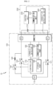
- FIG. 2 is a diagram schematically showing an exemplary configuration of the battery pack 100 according to an embodiment of the present disclosure and a load 200.
- the battery pack 100 may include a battery cell 110, a main relay 120, a precharge relay 130, a precharge resistor 140, a connector 150, a communication part 160, and a controller 170.
- the battery cell 110 refers to one physically separable independent cell including a negative electrode terminal and a positive electrode terminal.
- one pouch-type lithium polymer cell may be regarded as the battery cell 110.
- the battery pack 100 includes at least one battery cell 110, a main relay 120 provided on a charging and discharging path L of the battery cell 110, and a precharge relay 130 and a precharge resistor 140 connected in parallel to the main relay 120 on the charging and discharging path L.
- the main relay 120 may be configured to have one end connected to one end of the battery cell 110 and the other end connected to the connector 150.
- the main relay 120 may be provided on the charging and discharging path L.
- the charging and discharging path L is a current path provided inside the battery pack 100, and may be a high current path that connects a positive electrode terminal P+ of the battery pack 100, the battery cell 110, and a negative electrode terminal P- of the battery pack 100.
- One end of the main relay 120 may be connected to the positive electrode of the battery cell 110, and the other end of the main relay 120 may be connected to the positive electrode terminal P+ of the battery pack 100.
- a second main relay 121 may be provided between the negative electrode of the battery cell 110 and the negative electrode terminal P- of the battery pack 100. That is, the main relay 120 may be provided at the positive electrode of the battery cell 110, and the second main relay 121 may be provided at the negative electrode of the battery cell 110.
- the precharge relay 130 may be configured to have one end connected between one end of the battery cell 110 and one end of the main relay 120 on the charging and discharging path L and the other end connected to one end of the precharge resistor 140.
- the precharge resistor 140 is configured to have one end connected to the other end of the precharge relay 130 and the other end connected between the other end of the main relay 120 and the connector 150 on the charging and discharging path L.
- the precharge relay 130 and the precharge resistor 140 may be connected in series with each other, and may be connected in parallel with the main relay 120 on the charging and discharging path L.
- the connector 150 may be configured to allow a load 200 including a capacitor 210 to be connected thereto.
- the connector 150 may include a positive electrode terminal P+ of the battery pack 100 and a negative electrode terminal P- of the battery pack 100.
- the positive electrode terminal P+ and the negative electrode terminal P- of the battery pack 100 may be included in the connector 150.
- the load 200 since the load 200 is connected to the connector 150, the battery pack 100 and the load 200 may be connected to each other.
- the communication part 160 may be configured to receive a capacitance of the capacitor 210 from the load 200 through the connector 150, when the load 200 is connected to the connector 150.
- the communication part 160 may communicate with the load 200 by wire and/or wirelessly.
- the embodiment of FIG. 2 may be an embodiment in which the communication part 160 communicates with the load 200 through a wired line. That is, in the embodiment of FIG. 2 , the communication part 160 may be connected to the connector 150 and connected to the load 200 through the connector 150 by wire. Through the wired line, the communication part 160 may receive the capacitance from the load 200.
- the controller 170 may be configured to obtain the capacitance from the communication part 160.
- the controller 170 and the communication part 160 may be connected to communicate with each other.
- the controller 170 may obtain the capacitance from the communication part 160.
- controller 170 may be configured to calculate a duty ratio corresponding to the capacitance.
- controller 170 may be configured to precharge the capacitor 210 by controlling the operation state of the precharge relay 130 according to the calculated duty ratio.
- the duty ratio may be an ON/OFF ratio for controlling the operation state of the precharge relay 130.
- the controller 170 may alternately control the operation state of the precharge relay 130 to a turn-on state or a turn-off state according to the calculated duty ratio. Through this process, the capacitor 210 included in the load 200 is charged, thereby completing the precharge.
- the operation state of the main relay 120 may be a turn-off state, and the operation state of the second main relay 121 may be a turn-on state.
- the operation state of the precharge relay 130 may be controlled according to the duty ratio calculated by the controller 170.
- the capacitance of the capacitor 210 included in the load 200 may be known in advance or may be checked by directly measuring the capacitance. In other words, since the capacitor 210 may be charged as much as the voltage corresponding to the capacitance only when the capacitance of the capacitor 210 of the load 200 is checked, it is most important to check the capacitance before performing the precharge in order to accurately perform the precharge.
- various products may be connected to the battery pack 100.
- these various products may include capacitors 210 having different capacitances according to specifications.
- the capacitance of some of the various products may not be set in advance in the controller 170, and the controller 170 may precharge the product by setting an incorrect duty ratio. If the precharge is insufficiently performed, a ripple current may be generated to damage an element included in the battery pack 100 and/or an internal element of the load 200.
- the battery pack 100 has an advantage of receiving and obtaining capacitance information of the capacitor 210 from the load 200 in advance before performing the precharge, and then performing the precharge based on the obtained capacitance.
- the battery pack 100 since the battery pack 100 according to an embodiment of the present disclosure may perform accurate precharge to correspond to the capacity of the capacitor 210 after receiving and obtaining the capacitance from the load 200 in advance, there is an advantage of having excellent versatility and compatibility for various products that can be charged with the battery pack 100.
- the controller 170 provided to the battery pack 100 may selectively include processors known in the art, application-specific integrated circuit (ASIC), other chipsets, logic circuits, registers, communication modems, data processing devices, and the like to execute various control logic performed in the present disclosure.
- ASIC application-specific integrated circuit
- the controller 170 may be implemented as a set of program modules.
- the program module may be stored in a memory and executed by the controller 170.
- the memory may be located inside or out of the controller 170 and may be connected to the controller 170 by various well-known means.
- the battery pack 100 may further include a storage part 180.
- the storage part 180 may be configured to map and store identification information of the load 200 and the capacitance.
- the identification information of the load 200 and the capacitance of the load 200 may be mapped and stored.
- the capacitance of the load 200 may be checked through the identification information of the load 200 stored in the storage part 180.
- the communication part 160 may be configured to further receive the identification information together with the capacitance from the load 200. That is, the identification information of the load 200 stored in the storage part 180 may be received by the communication part 160 from the load 200.
- the storage part 180 may map and store the identification information and the capacitance received by the communication part 160.
- the storage part 180 may store programs and data required for the controller 170. That is, the storage part 180 may store data necessary for operation and function of each component of the battery pack 100, data generated in the process of performing the operation or function, or the like.
- the storage part 130 is not particularly limited in its kind as long as it is a known information storage means that can record, erase, update and read data.
- the information storage means may include RAM, flash memory, ROM, EEPROM, registers, and the like.
- the storage part 180 may store program codes in which processes executable by the controller 170 are defined.
- the controller 170 may be configured to control the output power according to the battery cell 110 based on the capacitance received by the communication part 160 after the precharge of the capacitor 210 is completed.
- a power profile representing a correspondence between the capacitance of the capacitor 210 that may be included in the load 200 and the output power of the battery pack 100 may be preset.
- This power profile is configured to be used to determine the optimal output power corresponding to the capacitance of the capacitor 210 included in the load, and may be stored in advance in the storage part 180.
- the optimal output power for the load 200 may not be determined. That is, since the capacitance of the capacitor 210 included in the load 200 is not accurately recognized, the optimal output power for the load 200 may not be determined even when the power profile is considered. In this case, since the output power of the battery pack 100 is not controlled to the optimum output power, when the load 200 is charged by the battery pack 100, a ripple current or a reverse voltage may be applied.
- charging by the battery pack 100 may be unstable because the optimal output power is not determined even if the power profile is considered for a product whose capacitance is not preset.
- the battery pack 100 according to an embodiment of the present disclosure has an advantage of outputting power optimized to the load 200 based on the capacitance as well as performing precharge based on the capacitance directly received from the load 200. That is, the battery pack 100 according to an embodiment of the present disclosure has an advantage of charging the load 200 stably.
- the controller 170 may be configured to obtain the identification information and the capacitance received by the communication part 160.
- the controller 170 may obtain both the identification information and the capacitance received by the communication part 160 from the load 200.
- controller 170 may be configured to compare the obtained identification information with the identification information stored in the storage part 180 to determine whether to store the identification information and the obtained capacitance.
- the controller 170 may be configured to map the obtained identification information and the obtained capacitance and store the same in the storage part 180.
- a new product hereinafter, a first load
- identification information and capacitance for the first load may not be stored in the storage part 180.
- the communication part 160 may receive the identification information of the first load and the capacitance of the capacitor 210 included in the first load from the first load.
- the controller 170 may map and store the first identification information of the first load and the first capacitance received by the communication part 160 in the storage part 180. Thereafter, the controller 170 may set a first duty ratio corresponding to the first load based on the first capacitance of the first load.
- the controller 170 may precharge the capacitor 210 included in the first load by controlling the operation state of the precharge relay 130 according to the set first duty ratio.
- the controller 170 may be configured to update the stored capacitance to the obtained capacitance to correspond to the stored identification information.
- the capacitor 210 may be changed because the second load is repaired or changed.
- the product is the same as a product that has already been connected to the battery pack 100
- the second load whose capacitor 210 is changed may be connected to the battery pack 100 as the manufacturing specifications are changed.
- the storage part 180 may store identification information and capacitance for a product that has already been connected. That is, even though second identification information of the second load received by the communication part 160 from the second load is the same as the identification information already stored in the storage part 180, the second capacitance of the second load received by the communication part 160 may be different from the capacitance already stored in the storage part 180. Accordingly, the controller 170 may obtain the second identification information and the second capacitance of the second load from the communication part 160, and update the capacitance corresponding to the identification information of the second load stored in the storage part 180 to the newly obtained second capacitance. Thereafter, the controller 170 may set a second duty ratio corresponding to the second load based on the updated second capacitance of the second load. In addition, the controller 170 may precharge the capacitor 210 included in the second load by controlling the operation state of the precharge relay 130 according to the set second duty ratio.
- FIG. 3 is a diagram schematically showing a battery system 10 according to another embodiment of the present disclosure.
- the battery system 10 may include the battery pack 100 according to an embodiment of the present disclosure and a load 200.
- the load 200 may include a capacitor 210, a communication unit 220, and a control unit 230.
- the capacitor 210 may be configured to have one end connected to the positive electrode terminal P+ of the battery pack 100 and the other end connected to the negative electrode terminal P- of the battery pack 100.
- one end of the capacitor 210 may be connected to the positive electrode terminal P+ of the battery pack 100 by being connected to the connector 150.
- the other end of the capacitor 210 may be connected to the negative electrode terminal P- of the battery pack 100 by being connected to the connector 150. Accordingly, when the capacitor 210 is connected to the connector, a closed circuit connecting the positive electrode terminal P+ of the battery pack 100, the battery cell 110, the negative electrode terminal P- of the battery pack 100, and the capacitor 210 may be formed.
- the communication unit 220 may be configured to be communicatively connected to the communication part 160.
- the communication unit 220 may be configured to communicate with the communication part 160 by wire and/or wirelessly.
- the communication unit 220 may be communicatively connected to the communication part 160 through a wired line.
- the communication unit 220 may be connected to the connector 150 and may be connected to the communication part 160 by wire through the connector 150.
- the control unit 230 may be configured to control the communication unit 220 to output the capacitance of the capacitor 210 and the identification information of the load 200 to the communication part 160.
- the battery pack 100 may further include a connection detector 190.
- the connection detector 190 may be configured to detect a connection between the load 200 and the connector 150, and output a connection detection signal when the connection between the load 200 and the connector 150 is detected.
- connection detector 190 may detect whether the positive electrode terminal P+ and the negative electrode terminal P- of the battery pack 100 are connected to the capacitor 210.
- connection detection signal output by the connection detector 190 may be output to the controller 170.
- the controller 170 may be configured to output a request signal for requesting the capacitance of the capacitor 210 and the identification information of the load 200 to the communication unit 220 through the communication part 160.
- the controller 170 may determine that the battery pack 100 and the load 200 are connected. In addition, when the battery pack 100 and the load 200 are connected, the communication part 160 of the battery pack 100 and the communication unit 220 of the load 200 may be connected to communicate with each other. Accordingly, the controller 170 may control the communication part 160 to output a request signal for requesting the identification information and the capacitance to the communication unit 220.
- the controller 170 may obtain the capacitance by outputting the request signal to the load 200 before performing the precharge (when the battery pack 100 and the load 200 are connected) in order to accurately perform the precharge.
- the controller 170 may set a duty ratio corresponding to the obtained capacitance and perform precharge according to the set duty ratio.
- the battery system 10 has an advantage of preventing unexpected problems that may occur due to incompletely performed precharge in advance by obtaining the capacitance information first and then performing precharge to correspond to the obtained capacitance.
- the control unit 230 may be configured to receive the request signal through the communication unit 220.
- the controller 170 of the battery pack 100 when the controller 170 of the battery pack 100 receives the connection detection signal from the connection detector 190, it may output a request signal for requesting the identification information of the load 200 and the capacitance.
- the control unit 230 of the load 200 may receive the request signal through the communication unit 220.
- the control unit 230 may be configured to generate a response signal including the identification information and the capacitance in response to the request signal, and to control the communication unit 220 to output the response signal to the communication part 160.
- control unit 230 may generate a response signal including the identification information of the load 200 and the capacitance of the capacitor 210 included in the load 200. That is, the response signal generated by the control unit 230 may correspond to the request signal generated by the controller 170.
- the control unit 230 may output the generated response signal through the communication unit 220.
- the response signal output through the communication unit 220 may be received by the controller 170 through the communication part 160.
- the load 200 may further include a connection detection unit 240.
- the connection detection unit 240 may be configured to detect a connection to the connector 150, and to output a connection signal to the control unit 230 when the connection to the connector 150 is detected.
- connection detection unit 240 provided in the load 200 may have a configuration corresponding to the connection detector 190 provided in the battery pack 100.
- the control unit 230 may be configured to control the communication unit 220 to output the capacitance and the identification information to the communication part 160, when receiving the connection signal from the connection detection unit 240.
- control unit 230 may output the capacitance and the identification information not only when the response signal is received through the communication unit 220 but also when the connection signal is received from the connection detection unit 240.
- connection detector 190 may not determine whether the battery pack 100 and the load 200 are connected since a defect occurs in the connection detector 190 provided in the battery pack 100.
- the control unit 230 can output the response signal only when receiving the request signal, precharge may not proceed or may be performed incorrectly.
- the load 200 may further include the connection detection unit 240 to determine whether the battery pack 100 and the load 200 are connected, and the control unit 230 may output the capacitance and the identification information through the communication unit 220 based on the connection signal.
- the control unit 230 may output the capacitance and the identification information through the communication unit 220 after a predetermined time elapses from receiving the connection signal. That is, after receiving the connection signal, the control unit 230 may wait for a time (a predetermined time) for receiving the request signal if the state of the connection detector 190 is normal. In addition, the control unit 230 may output the capacitance and the identification information through the communication unit 220 when the request signal is not received for a predetermined time.
- At least some of the components of the battery pack 100 may be implemented by supplementing or adding functions of components included in a conventional BMS.
- the communication part 160, the controller 170, the storage part 180, and the connection detector 190 of the battery pack 100 may be implemented as components of the BMS.
- such a BMS may be provided in the battery pack 100.
- FIG. 4 is a diagram schematically showing a precharge method according to still another embodiment of the present disclosure.
- the precharge method may be applied to the battery pack 100 or the battery system 10 according to an embodiment of the present disclosure. Preferably, each step of the precharge method may be performed by the battery pack 100.
- the precharge method may include a receiving step (S 100), a duty ratio calculating step (S200), and a precharging step (S300).
- the receiving step (S100) is a step of receiving the capacitance of the capacitor 210 from the load 200 when the battery pack 100 and the load 200 are connected, and may be performed by communication part 160.
- the communication part 160 may receive the identification information of the load 200 along with the capacitance from the load 200.
- the duty ratio calculating step (S200) is a step of calculating a duty ratio corresponding to the capacitance, and may be performed by the controller 170.
- the controller 170 may obtain the capacitance of the capacitor 210 provided in the load 200 through the communication part 160, and may calculate the duty ratio corresponding to the obtained capacitance. That is, the controller 170 may improve the accuracy of the precharge by directly calculating the duty ratio optimized for the load 200 before performing the precharge.
- the precharging step (S300) is a step of precharging the capacitor 210 by controlling the operation state of the precharge relay 130 according to the calculated duty ratio, and may be performed by the controller 170.
- the controller 170 may control the operation state of the precharge relay 130 according to the calculated duty ratio. Through this, the capacitor 210 may be precharged.
- the embodiments of the present disclosure described above may not be implemented only through an apparatus and a method, but may be implemented through a program that realizes a function corresponding to the configuration of the embodiments of the present disclosure or a recording medium on which the program is recorded.
- the program or recording medium may be easily implemented by those skilled in the art from the above description of the embodiments.
Landscapes
- Engineering & Computer Science (AREA)
- Power Engineering (AREA)
- Manufacturing & Machinery (AREA)
- Chemical & Material Sciences (AREA)
- Chemical Kinetics & Catalysis (AREA)
- Electrochemistry (AREA)
- General Chemical & Material Sciences (AREA)
- Microelectronics & Electronic Packaging (AREA)
- Charge And Discharge Circuits For Batteries Or The Like (AREA)
- Secondary Cells (AREA)
Abstract
Description
- The present application claims priority to
Korean Patent Application No. 10-2020-0128999 filed on October 6, 2020 - The present disclosure relates to a battery pack, a battery system and a precharge method, and more particularly, to a battery pack, a battery system and a precharge method, which may accurately perform precharging by obtaining a capacitance of a capacitor at a load.
- Recently, the demand for portable electronic products such as notebook computers, video cameras and portable telephones has increased sharply, and electric vehicles, energy storage batteries, robots, satellites and the like have been developed in earnest. Accordingly, high-performance batteries allowing repeated charging and discharging are being actively studied.
- Batteries commercially available at present include nickel-cadmium batteries, nickel hydrogen batteries, nickel-zinc batteries, lithium batteries and the like. Among them, the lithium batteries are in the limelight since they have almost no memory effect compared to nickel-based batteries and also have very low self-charging rate and high energy density.
- Conventionally, a precharge circuit is configured in parallel inside the battery pack, and before the capacitor of the battery and the load is connected to a main relay, the voltage is charged to the capacitor through the precharge circuit, and then the main relay is connected to prevent an excessive current caused by a voltage difference, thereby preventing an arc from occurring.
- However, in order to perform the precharge, it is required to acquire the capacitance of the capacitor. Conventionally, the specifications of the load that can be connected to the battery pack are set in advance, so the capacitance of the capacitor could be known in advance. Alternatively, conventionally, the battery pack or the load directly measures the capacitance of the capacitor, thereby checking the capacitance at the battery pack.
- That is, conventionally, there is a problem that it is compatible only with a load whose capacitance is known in advance, and there is a problem that a measurement module for directly measuring the capacitance must be provided.
- The present disclosure is designed to solve the problems of the related art, and therefore the present disclosure is directed to providing a battery pack, a battery system and a precharge method, which receives a capacitance of a capacitor from a load before performing the precharge to obtain the capacitance and performs the precharge according to a duty ratio calculated based on the obtained capacitance.
- These and other objects and advantages of the present disclosure may be understood from the following detailed description and will become more fully apparent from the exemplary embodiments of the present disclosure. Also, it will be easily understood that the objects and advantages of the present disclosure may be realized by the means shown in the appended claims and combinations thereof.
- A battery pack according to one aspect of the present disclosure is a battery pack, which includes at least one battery cell, a main relay provided on a charging and discharging path of the battery cell, and a precharge relay and a precharge resistor connected in parallel to the main relay on the charging and discharging path, and the battery pack may comprise: a connector configured such that a load including a capacitor is connected thereto; a communication part configured to receive a capacitance of the capacitor from the load through the connector, when the load is connected to the connector; and a controller configured to obtain the capacitance from the communication part, calculate a duty ratio corresponding to the capacitance, and precharge the capacitor by controlling an operation state of the precharge relay according to the calculated duty ratio.
- A battery pack according to another aspect of the present disclosure may further comprise a storage part configured to map and store identification information of the load and the capacitance.
- The communication part may be configured to further receive the identification information together with the capacitance from the load.
- The controller may be configured to obtain the identification information and the capacitance received by the communication part, and determine whether to store the identification information and the obtained capacitance by comparing the obtained identification information with the identification information stored in the storage part.
- The controller may be configured to map and store the obtained identification information and the obtained capacitance in the storage part, when the obtained identification information is not stored in the storage part.
- When the obtained identification information is stored in the storage part but the obtained capacitance is different from the capacitance stored in the storage part, the controller may be configured to update the stored capacitance to the obtained capacitance to correspond to the stored identification information.
- The main relay may be configured to have one end connected to one end of the battery cell and the other end connected to the connector.
- The precharge relay may be configured to have one end connected between one end of the battery cell and one end of the main relay on the charging and discharging path and the other end connected to one end of the precharge resistor.
- The precharge resistor may be configured to have one end connected to the other end of the precharge relay and the other end connected between the other end of the main relay and the connector on the charging and discharging path.
- A battery system according to still another aspect of the present disclosure may comprise the battery pack according to one aspect of the present disclosure; and the load.
- The load may be configured to include: a capacitor configured to have one end connected to a positive electrode terminal of the battery pack and the other end connected to a negative electrode terminal of the battery pack; a communication unit communicatively connected to the communication part; and a control unit configured to control the communication unit to output the capacitance of the capacitor and the identification information of the load to the communication part.
- A battery pack according to still another aspect of the present disclosure may further include a connection detector configured to detect a connection between the load and the connector and output a connection detection signal when the connection between the load and the connector is detected.
- The controller may be configured to output a request signal for requesting the capacitance of the capacitor and the identification information of the load to the communication unit through the communication part, when the connection detection signal is received from the connection detector.
- The control unit may be configured to receive the request signal through the communication unit, generate a response signal including the identification information and the capacitance in response to the request signal, and control the communication unit to output the response signal to the communication part.
- The load may further include a connection detection unit configured to detect a connection to the connector and output a connection signal to the control unit when the connection to the connector is detected.
- The control unit may be configured to control the communication unit to output the capacitance and the identification information to the communication part, when the connection signal is received from the connection detection unit.
- A precharge method according to still another aspect of the present disclosure is a precharge method of a battery pack that includes at least one battery cell, a main relay provided on a charging and discharging path of the battery cell, and a precharge relay and a precharge resistor connected in parallel to the main relay on the charging and discharging path and is configured to be connected to a load including a capacitor, and the precharge method may comprise: a capacitance receiving step of receiving a capacitance of the capacitor from the load, when the battery pack and the load are connected; a duty ratio calculating step of calculating a duty ratio corresponding to the capacitance; and a precharging step of precharging the capacitor by controlling an operation state of the precharge relay according to the calculated duty ratio.
- According to one aspect of the present disclosure, there is an advantage in that capacitance information of the capacitor is received and obtained from the load in advance before performing the precharge, and then the precharge may be performed based on the obtained capacitance.
- The effects of the present disclosure are not limited to the effects mentioned above, and other effects not mentioned will be clearly understood by those skilled in the art from the description of the claims.
- The accompanying drawings illustrate a preferred embodiment of the present disclosure and together with the foregoing disclosure, serve to provide further understanding of the technical features of the present disclosure, and thus, the present disclosure is not construed as being limited to the drawing.
-
FIG. 1 is a diagram schematically showing a battery pack according to an embodiment of the present disclosure. -
FIG. 2 is a diagram schematically showing an exemplary configuration of the battery pack according to an embodiment of the present disclosure and a load. -
FIG. 3 is a diagram schematically showing a battery system according to another embodiment of the present disclosure. -
FIG. 4 is a diagram schematically showing a precharge method according to still another embodiment of the present disclosure. - It should be understood that the terms used in the specification and the appended claims should not be construed as limited to general and dictionary meanings, but interpreted based on the meanings and concepts corresponding to technical aspects of the present disclosure on the basis of the principle that the inventor is allowed to define terms appropriately for the best explanation.
- Therefore, the description proposed herein is just a preferable example for the purpose of illustrations only, not intended to limit the scope of the disclosure, so it should be understood that other equivalents and modifications could be made thereto without departing from the scope of the disclosure.
- Additionally, in describing the present disclosure, when it is deemed that a detailed description of relevant known elements or functions renders the key subject matter of the present disclosure ambiguous, the detailed description is omitted herein.
- The terms including the ordinal number such as "first", "second" and the like, may be used to distinguish one element from another among various elements, but not intended to limit the elements by the terms.
- Throughout the specification, when a portion is referred to as "comprising" or "including" any element, it means that the portion may include other elements further, without excluding other elements, unless specifically stated otherwise.
- Furthermore, the term "controller" described in the specification refers to a unit that processes at least one function or operation, and may be implemented by hardware, software, or a combination of hardware and software.
- In addition, throughout the specification, when a portion is referred to as being "connected" to another portion, it is not limited to the case that they are "directly connected", but it also includes the case where they are "indirectly connected" with another element being interposed between them.
- Hereinafter, preferred embodiments of the present disclosure will be described in detail with reference to the accompanying drawings.
-
FIG. 1 is a diagram schematically showing abattery pack 100 according to an embodiment of the present disclosure.FIG. 2 is a diagram schematically showing an exemplary configuration of thebattery pack 100 according to an embodiment of the present disclosure and aload 200. - Referring to
FIG. 1 , thebattery pack 100 according to an embodiment of the present disclosure may include abattery cell 110, amain relay 120, aprecharge relay 130, aprecharge resistor 140, aconnector 150, acommunication part 160, and acontroller 170. - Here, the
battery cell 110 refers to one physically separable independent cell including a negative electrode terminal and a positive electrode terminal. For example, one pouch-type lithium polymer cell may be regarded as thebattery cell 110. - Specifically, the
battery pack 100 includes at least onebattery cell 110, amain relay 120 provided on a charging and discharging path L of thebattery cell 110, and aprecharge relay 130 and aprecharge resistor 140 connected in parallel to themain relay 120 on the charging and discharging path L. - The
main relay 120 may be configured to have one end connected to one end of thebattery cell 110 and the other end connected to theconnector 150. - For example, in the embodiment of
FIG. 2 , themain relay 120 may be provided on the charging and discharging path L. Here, the charging and discharging path L is a current path provided inside thebattery pack 100, and may be a high current path that connects a positive electrode terminal P+ of thebattery pack 100, thebattery cell 110, and a negative electrode terminal P- of thebattery pack 100. One end of themain relay 120 may be connected to the positive electrode of thebattery cell 110, and the other end of themain relay 120 may be connected to the positive electrode terminal P+ of thebattery pack 100. - In addition, in the embodiment of
FIG. 2 , a secondmain relay 121 may be provided between the negative electrode of thebattery cell 110 and the negative electrode terminal P- of thebattery pack 100. That is, themain relay 120 may be provided at the positive electrode of thebattery cell 110, and the secondmain relay 121 may be provided at the negative electrode of thebattery cell 110. - The
precharge relay 130 may be configured to have one end connected between one end of thebattery cell 110 and one end of themain relay 120 on the charging and discharging path L and the other end connected to one end of theprecharge resistor 140. - The
precharge resistor 140 is configured to have one end connected to the other end of theprecharge relay 130 and the other end connected between the other end of themain relay 120 and theconnector 150 on the charging and discharging path L. - That is, the
precharge relay 130 and theprecharge resistor 140 may be connected in series with each other, and may be connected in parallel with themain relay 120 on the charging and discharging path L. - The
connector 150 may be configured to allow aload 200 including acapacitor 210 to be connected thereto. Specifically, theconnector 150 may include a positive electrode terminal P+ of thebattery pack 100 and a negative electrode terminal P- of thebattery pack 100. - For example, in the embodiment of
FIG. 2 , the positive electrode terminal P+ and the negative electrode terminal P- of thebattery pack 100 may be included in theconnector 150. In addition, since theload 200 is connected to theconnector 150, thebattery pack 100 and theload 200 may be connected to each other. - The
communication part 160 may be configured to receive a capacitance of thecapacitor 210 from theload 200 through theconnector 150, when theload 200 is connected to theconnector 150. - For example, the
communication part 160 may communicate with theload 200 by wire and/or wirelessly. The embodiment ofFIG. 2 may be an embodiment in which thecommunication part 160 communicates with theload 200 through a wired line. That is, in the embodiment ofFIG. 2 , thecommunication part 160 may be connected to theconnector 150 and connected to theload 200 through theconnector 150 by wire. Through the wired line, thecommunication part 160 may receive the capacitance from theload 200. - The
controller 170 may be configured to obtain the capacitance from thecommunication part 160. - Preferably, the
controller 170 and thecommunication part 160 may be connected to communicate with each other. When thecommunication part 160 receives the capacitance from theload 200, thecontroller 170 may obtain the capacitance from thecommunication part 160. - Also, the
controller 170 may be configured to calculate a duty ratio corresponding to the capacitance. In addition, thecontroller 170 may be configured to precharge thecapacitor 210 by controlling the operation state of theprecharge relay 130 according to the calculated duty ratio. - Here, the duty ratio may be an ON/OFF ratio for controlling the operation state of the
precharge relay 130. Specifically, thecontroller 170 may alternately control the operation state of theprecharge relay 130 to a turn-on state or a turn-off state according to the calculated duty ratio. Through this process, thecapacitor 210 included in theload 200 is charged, thereby completing the precharge. - Meanwhile, in the embodiment of
FIG. 2 , while the precharge is in progress, the operation state of themain relay 120 may be a turn-off state, and the operation state of the secondmain relay 121 may be a turn-on state. In addition, the operation state of theprecharge relay 130 may be controlled according to the duty ratio calculated by thecontroller 170. - In general, for the precharge, the capacitance of the
capacitor 210 included in theload 200 may be known in advance or may be checked by directly measuring the capacitance. In other words, since thecapacitor 210 may be charged as much as the voltage corresponding to the capacitance only when the capacitance of thecapacitor 210 of theload 200 is checked, it is most important to check the capacitance before performing the precharge in order to accurately perform the precharge. - However, it is practically impossible to know the capacitance of various types of
loads 200 that can be connected to thebattery pack 100 in advance. Also, it can be inefficient to measure the capacitance of theload 200 every time for the precharge in that the capacitance measurement module is forced. - For example, when the
battery pack 100 is used for home use, various products may be connected to thebattery pack 100. In addition, these various products may includecapacitors 210 having different capacitances according to specifications. In this case, the capacitance of some of the various products may not be set in advance in thecontroller 170, and thecontroller 170 may precharge the product by setting an incorrect duty ratio. If the precharge is insufficiently performed, a ripple current may be generated to damage an element included in thebattery pack 100 and/or an internal element of theload 200. - Therefore, the
battery pack 100 according to an embodiment of the present disclosure has an advantage of receiving and obtaining capacitance information of thecapacitor 210 from theload 200 in advance before performing the precharge, and then performing the precharge based on the obtained capacitance. - In other words, since the
battery pack 100 according to an embodiment of the present disclosure may perform accurate precharge to correspond to the capacity of thecapacitor 210 after receiving and obtaining the capacitance from theload 200 in advance, there is an advantage of having excellent versatility and compatibility for various products that can be charged with thebattery pack 100. - Meanwhile, the
controller 170 provided to thebattery pack 100 according to an embodiment of the present disclosure may selectively include processors known in the art, application-specific integrated circuit (ASIC), other chipsets, logic circuits, registers, communication modems, data processing devices, and the like to execute various control logic performed in the present disclosure. Also, when the control logic is implemented in software, thecontroller 170 may be implemented as a set of program modules. At this time, the program module may be stored in a memory and executed by thecontroller 170. The memory may be located inside or out of thecontroller 170 and may be connected to thecontroller 170 by various well-known means. - Referring to
FIGS. 1 and2 , thebattery pack 100 according to an embodiment of the present disclosure may further include astorage part 180. - The
storage part 180 may be configured to map and store identification information of theload 200 and the capacitance. - That is, in the
storage part 180, the identification information of theload 200 and the capacitance of theload 200 may be mapped and stored. For example, the capacitance of theload 200 may be checked through the identification information of theload 200 stored in thestorage part 180. - The
communication part 160 may be configured to further receive the identification information together with the capacitance from theload 200. That is, the identification information of theload 200 stored in thestorage part 180 may be received by thecommunication part 160 from theload 200. - For example, when the
communication part 160 receives the identification information and the capacitance from theload 200, thestorage part 180 may map and store the identification information and the capacitance received by thecommunication part 160. - In addition, the
storage part 180 may store programs and data required for thecontroller 170. That is, thestorage part 180 may store data necessary for operation and function of each component of thebattery pack 100, data generated in the process of performing the operation or function, or the like. Thestorage part 130 is not particularly limited in its kind as long as it is a known information storage means that can record, erase, update and read data. As an example, the information storage means may include RAM, flash memory, ROM, EEPROM, registers, and the like. In addition, thestorage part 180 may store program codes in which processes executable by thecontroller 170 are defined. - Meanwhile, the
controller 170 may be configured to control the output power according to thebattery cell 110 based on the capacitance received by thecommunication part 160 after the precharge of thecapacitor 210 is completed. - Preferably, a power profile representing a correspondence between the capacitance of the
capacitor 210 that may be included in theload 200 and the output power of thebattery pack 100 may be preset. This power profile is configured to be used to determine the optimal output power corresponding to the capacitance of thecapacitor 210 included in the load, and may be stored in advance in thestorage part 180. - If the capacitance of the
capacitor 210 included in theload 200 is not preset in thecontroller 170, the optimal output power for theload 200 may not be determined. That is, since the capacitance of thecapacitor 210 included in theload 200 is not accurately recognized, the optimal output power for theload 200 may not be determined even when the power profile is considered. In this case, since the output power of thebattery pack 100 is not controlled to the optimum output power, when theload 200 is charged by thebattery pack 100, a ripple current or a reverse voltage may be applied. - For example, when various products can be connected to the
battery pack 100, charging by thebattery pack 100 may be unstable because the optimal output power is not determined even if the power profile is considered for a product whose capacitance is not preset. - Therefore, the
battery pack 100 according to an embodiment of the present disclosure has an advantage of outputting power optimized to theload 200 based on the capacitance as well as performing precharge based on the capacitance directly received from theload 200. That is, thebattery pack 100 according to an embodiment of the present disclosure has an advantage of charging theload 200 stably. - The
controller 170 may be configured to obtain the identification information and the capacitance received by thecommunication part 160. - For example, in the embodiment of
FIG. 2 , thecontroller 170 may obtain both the identification information and the capacitance received by thecommunication part 160 from theload 200. - In addition, the
controller 170 may be configured to compare the obtained identification information with the identification information stored in thestorage part 180 to determine whether to store the identification information and the obtained capacitance. - Specifically, when the obtained identification information is not stored in the
storage part 180, thecontroller 170 may be configured to map the obtained identification information and the obtained capacitance and store the same in thestorage part 180. - For example, when a new product (hereinafter, a first load) is connected to the
battery pack 100, identification information and capacitance for the first load may not be stored in thestorage part 180. Thecommunication part 160 may receive the identification information of the first load and the capacitance of thecapacitor 210 included in the first load from the first load. Thecontroller 170 may map and store the first identification information of the first load and the first capacitance received by thecommunication part 160 in thestorage part 180. Thereafter, thecontroller 170 may set a first duty ratio corresponding to the first load based on the first capacitance of the first load. In addition, thecontroller 170 may precharge thecapacitor 210 included in the first load by controlling the operation state of theprecharge relay 130 according to the set first duty ratio. - Also, when the obtained identification information is stored in the
storage part 180 but the obtained capacitance is different from the capacitance stored in thestorage part 180, thecontroller 170 may be configured to update the stored capacitance to the obtained capacitance to correspond to the stored identification information. - For example, although the same product (hereinafter referred to as a second load) as a product that has already been connected to the
battery pack 100 is connected again, thecapacitor 210 may be changed because the second load is repaired or changed. Alternatively, although the product is the same as a product that has already been connected to thebattery pack 100, the second load whosecapacitor 210 is changed may be connected to thebattery pack 100 as the manufacturing specifications are changed. - In this case, the
storage part 180 may store identification information and capacitance for a product that has already been connected. That is, even though second identification information of the second load received by thecommunication part 160 from the second load is the same as the identification information already stored in thestorage part 180, the second capacitance of the second load received by thecommunication part 160 may be different from the capacitance already stored in thestorage part 180. Accordingly, thecontroller 170 may obtain the second identification information and the second capacitance of the second load from thecommunication part 160, and update the capacitance corresponding to the identification information of the second load stored in thestorage part 180 to the newly obtained second capacitance. Thereafter, thecontroller 170 may set a second duty ratio corresponding to the second load based on the updated second capacitance of the second load. In addition, thecontroller 170 may precharge thecapacitor 210 included in the second load by controlling the operation state of theprecharge relay 130 according to the set second duty ratio. -
FIG. 3 is a diagram schematically showing abattery system 10 according to another embodiment of the present disclosure. - Referring to
FIG. 3 , thebattery system 10 according to another embodiment of the present disclosure may include thebattery pack 100 according to an embodiment of the present disclosure and aload 200. - In addition, the
load 200 may include acapacitor 210, acommunication unit 220, and acontrol unit 230. - The
capacitor 210 may be configured to have one end connected to the positive electrode terminal P+ of thebattery pack 100 and the other end connected to the negative electrode terminal P- of thebattery pack 100. - For example, in the embodiment of
FIG. 2 , one end of thecapacitor 210 may be connected to the positive electrode terminal P+ of thebattery pack 100 by being connected to theconnector 150. Also, the other end of thecapacitor 210 may be connected to the negative electrode terminal P- of thebattery pack 100 by being connected to theconnector 150. Accordingly, when thecapacitor 210 is connected to the connector, a closed circuit connecting the positive electrode terminal P+ of thebattery pack 100, thebattery cell 110, the negative electrode terminal P- of thebattery pack 100, and thecapacitor 210 may be formed. - The
communication unit 220 may be configured to be communicatively connected to thecommunication part 160. - The
communication unit 220 may be configured to communicate with thecommunication part 160 by wire and/or wirelessly. - For example, in the embodiment of
FIG. 2 , thecommunication unit 220 may be communicatively connected to thecommunication part 160 through a wired line. Thecommunication unit 220 may be connected to theconnector 150 and may be connected to thecommunication part 160 by wire through theconnector 150. - The
control unit 230 may be configured to control thecommunication unit 220 to output the capacitance of thecapacitor 210 and the identification information of theload 200 to thecommunication part 160. - Referring to
FIGS. 1 and2 , thebattery pack 100 may further include aconnection detector 190. - The
connection detector 190 may be configured to detect a connection between theload 200 and theconnector 150, and output a connection detection signal when the connection between theload 200 and theconnector 150 is detected. - Preferably, the
connection detector 190 may detect whether the positive electrode terminal P+ and the negative electrode terminal P- of thebattery pack 100 are connected to thecapacitor 210. In addition, the connection detection signal output by theconnection detector 190 may be output to thecontroller 170. - Upon receiving the connection detection signal from the
connection detector 190, thecontroller 170 may be configured to output a request signal for requesting the capacitance of thecapacitor 210 and the identification information of theload 200 to thecommunication unit 220 through thecommunication part 160. - Specifically, when receiving the connection detection signal from the
connection detector 190, thecontroller 170 may determine that thebattery pack 100 and theload 200 are connected. In addition, when thebattery pack 100 and theload 200 are connected, thecommunication part 160 of thebattery pack 100 and thecommunication unit 220 of theload 200 may be connected to communicate with each other. Accordingly, thecontroller 170 may control thecommunication part 160 to output a request signal for requesting the identification information and the capacitance to thecommunication unit 220. - That is, the
controller 170 may obtain the capacitance by outputting the request signal to theload 200 before performing the precharge (when thebattery pack 100 and theload 200 are connected) in order to accurately perform the precharge. In addition, thecontroller 170 may set a duty ratio corresponding to the obtained capacitance and perform precharge according to the set duty ratio. - Therefore, the
battery system 10 according to another embodiment of the present disclosure has an advantage of preventing unexpected problems that may occur due to incompletely performed precharge in advance by obtaining the capacitance information first and then performing precharge to correspond to the obtained capacitance. - The
control unit 230 may be configured to receive the request signal through thecommunication unit 220. - For example, in the previous embodiment, when the
controller 170 of thebattery pack 100 receives the connection detection signal from theconnection detector 190, it may output a request signal for requesting the identification information of theload 200 and the capacitance. In addition, thecontrol unit 230 of theload 200 may receive the request signal through thecommunication unit 220. - The
control unit 230 may be configured to generate a response signal including the identification information and the capacitance in response to the request signal, and to control thecommunication unit 220 to output the response signal to thecommunication part 160. - Specifically, the
control unit 230 may generate a response signal including the identification information of theload 200 and the capacitance of thecapacitor 210 included in theload 200. That is, the response signal generated by thecontrol unit 230 may correspond to the request signal generated by thecontroller 170. Thecontrol unit 230 may output the generated response signal through thecommunication unit 220. The response signal output through thecommunication unit 220 may be received by thecontroller 170 through thecommunication part 160. - Referring to
FIGS. 2 and3 , theload 200 may further include aconnection detection unit 240. - The
connection detection unit 240 may be configured to detect a connection to theconnector 150, and to output a connection signal to thecontrol unit 230 when the connection to theconnector 150 is detected. - That is, the
connection detection unit 240 provided in theload 200 may have a configuration corresponding to theconnection detector 190 provided in thebattery pack 100. - The
control unit 230 may be configured to control thecommunication unit 220 to output the capacitance and the identification information to thecommunication part 160, when receiving the connection signal from theconnection detection unit 240. - That is, the
control unit 230 may output the capacitance and the identification information not only when the response signal is received through thecommunication unit 220 but also when the connection signal is received from theconnection detection unit 240. - For example, the
connection detector 190 may not determine whether thebattery pack 100 and theload 200 are connected since a defect occurs in theconnection detector 190 provided in thebattery pack 100. In this case, if thecontrol unit 230 can output the response signal only when receiving the request signal, precharge may not proceed or may be performed incorrectly. Accordingly, theload 200 may further include theconnection detection unit 240 to determine whether thebattery pack 100 and theload 200 are connected, and thecontrol unit 230 may output the capacitance and the identification information through thecommunication unit 220 based on the connection signal. - Preferably, when both the
connection detector 190 and theconnection detection unit 240 operate normally, in order to prevent interference between the request signal output by thecommunication part 160 and the signal output by thecommunication unit 220, thecontrol unit 230 may output the capacitance and the identification information through thecommunication unit 220 after a predetermined time elapses from receiving the connection signal. That is, after receiving the connection signal, thecontrol unit 230 may wait for a time (a predetermined time) for receiving the request signal if the state of theconnection detector 190 is normal. In addition, thecontrol unit 230 may output the capacitance and the identification information through thecommunication unit 220 when the request signal is not received for a predetermined time. - At least some of the components of the
battery pack 100 according to an embodiment of the present disclosure may be implemented by supplementing or adding functions of components included in a conventional BMS. For example, thecommunication part 160, thecontroller 170, thestorage part 180, and theconnection detector 190 of thebattery pack 100 may be implemented as components of the BMS. In addition, such a BMS may be provided in thebattery pack 100. -
FIG. 4 is a diagram schematically showing a precharge method according to still another embodiment of the present disclosure. - The precharge method may be applied to the
battery pack 100 or thebattery system 10 according to an embodiment of the present disclosure. Preferably, each step of the precharge method may be performed by thebattery pack 100. - Referring to
FIG. 4 , the precharge method may include a receiving step (S 100), a duty ratio calculating step (S200), and a precharging step (S300). - The receiving step (S100) is a step of receiving the capacitance of the
capacitor 210 from theload 200 when thebattery pack 100 and theload 200 are connected, and may be performed bycommunication part 160. - Preferably, when the
battery pack 100 and theload 200 are connected, thecommunication part 160 may receive the identification information of theload 200 along with the capacitance from theload 200. - The duty ratio calculating step (S200) is a step of calculating a duty ratio corresponding to the capacitance, and may be performed by the
controller 170. - The
controller 170 may obtain the capacitance of thecapacitor 210 provided in theload 200 through thecommunication part 160, and may calculate the duty ratio corresponding to the obtained capacitance. That is, thecontroller 170 may improve the accuracy of the precharge by directly calculating the duty ratio optimized for theload 200 before performing the precharge. - The precharging step (S300) is a step of precharging the
capacitor 210 by controlling the operation state of theprecharge relay 130 according to the calculated duty ratio, and may be performed by thecontroller 170. - For example, in the embodiment of
FIG. 2 , thecontroller 170 may control the operation state of theprecharge relay 130 according to the calculated duty ratio. Through this, thecapacitor 210 may be precharged. - The embodiments of the present disclosure described above may not be implemented only through an apparatus and a method, but may be implemented through a program that realizes a function corresponding to the configuration of the embodiments of the present disclosure or a recording medium on which the program is recorded. The program or recording medium may be easily implemented by those skilled in the art from the above description of the embodiments.
- The present disclosure has been described in detail. However, it should be understood that the detailed description and specific examples, while indicating preferred embodiments of the disclosure, are given by way of illustration only, since various changes and modifications within the scope of the disclosure will become apparent to those skilled in the art from this detailed description.
- Additionally, many substitutions, modifications and changes may be made to the present disclosure described hereinabove by those skilled in the art without departing from the technical aspects of the present disclosure, and the present disclosure is not limited to the above-described embodiments and the accompanying drawings, and each embodiment may be selectively combined in part or in whole to allow various modifications.
-
- 10: battery system
- 100: battery pack
- 110: battery cell
- 120: main relay
- 121: second main relay
- 130: precharge relay
- 140: precharge resistor
- 150: connector
- 160: communication part
- 170: controller
- 180: storage part
- 190: connection detector
- 200: load
- 210: capacitor
- 220: communication unit
- 230: control unit
- 240: connection detection unit
Claims (10)
- A battery pack, which includes at least one battery cell, a main relay provided on a charging and discharging path of the battery cell, and a precharge relay and a precharge resistor connected in parallel to the main relay on the charging and discharging path, the battery pack comprising:a connector configured such that a load including a capacitor is connected thereto;a communication part configured to receive a capacitance of the capacitor from the load through the connector, when the load is connected to the connector; anda controller configured to obtain the capacitance from the communication part, calculate a duty ratio corresponding to the capacitance, and precharge the capacitor by controlling an operation state of the precharge relay according to the calculated duty ratio.
- The battery pack according to claim 1, further comprising:a storage part configured to map and store identification information of the load and the capacitance,wherein the communication part is configured to further receive the identification information together with the capacitance from the load.
- The battery pack according to claim 2,
wherein the controller is configured to obtain the identification information and the capacitance received by the communication part, and determine whether to store the identification information and the obtained capacitance by comparing the obtained identification information with the identification information stored in the storage part. - The battery pack according to claim 3,wherein the controller is configured to map and store the obtained identification information and the obtained capacitance in the storage part, when the obtained identification information is not stored in the storage part, andwherein when the obtained identification information is stored in the storage part but the obtained capacitance is different from the capacitance stored in the storage part, the controller is configured to update the stored capacitance to the obtained capacitance to correspond to the stored identification information.
- The battery pack according to claim 1,wherein the main relay is configured to have one end connected to one end of the battery cell and the other end connected to the connector,wherein the precharge relay is configured to have one end connected between one end of the battery cell and one end of the main relay on the charging and discharging path and the other end connected to one end of the precharge resistor, andwherein the precharge resistor is configured to have one end connected to the other end of the precharge relay and the other end connected between the other end of the main relay and the connector on the charging and discharging path.
- A battery system, comprising the battery pack according to any one of claims 1 to 5; and the load,
wherein the load is configured to include:a capacitor configured to have one end connected to a positive electrode terminal of the battery pack and the other end connected to a negative electrode terminal of the battery pack;a communication unit communicatively connected to the communication part; anda control unit configured to control the communication unit to output the capacitance of the capacitor and the identification information of the load to the communication part. - The battery system according to claim 6,wherein the battery pack further comprises a connection detector configured to detect a connection between the load and the connector and output a connection detection signal when the connection between the load and the connector is detected, andwherein the controller is configured to output a request signal for requesting the capacitance of the capacitor and the identification information of the load to the communication unit through the communication part, when the connection detection signal is received from the connection detector.
- The battery system according to claim 7,
wherein the control unit is configured to receive the request signal through the communication unit, generate a response signal including the identification information and the capacitance in response to the request signal, and control the communication unit to output the response signal to the communication part. - The battery system according to claim 6,wherein the load further includes a connection detection unit configured to detect a connection to the connector and output a connection signal to the control unit when the connection to the connector is detected, andwherein the control unit is configured to control the communication unit to output the capacitance and the identification information to the communication part, when the connection signal is received from the connection detection unit.
- A precharge method of a battery pack that includes at least one battery cell, a main relay provided on a charging and discharging path of the battery cell, and a precharge relay and a precharge resistor connected in parallel to the main relay on the charging and discharging path and is configured to be connected to a load including a capacitor, the precharge method comprising:a capacitance receiving step of receiving a capacitance of the capacitor from the load, when the battery pack and the load are connected;a duty ratio calculating step of calculating a duty ratio corresponding to the capacitance; anda precharging step of precharging the capacitor by controlling an operation state of the precharge relay according to the calculated duty ratio.
Applications Claiming Priority (2)
| Application Number | Priority Date | Filing Date | Title |
|---|---|---|---|
| KR1020200128999A KR102722929B1 (en) | 2020-10-06 | 2020-10-06 | Battery pack, battery system, and method for pre-charging |
| PCT/KR2021/013638 WO2022075712A1 (en) | 2020-10-06 | 2021-10-05 | Battery pack, battery system, and pre-charge method |
Publications (2)
| Publication Number | Publication Date |
|---|---|
| EP4156445A1 true EP4156445A1 (en) | 2023-03-29 |
| EP4156445A4 EP4156445A4 (en) | 2023-11-29 |
Family
ID=81126994
Family Applications (1)
| Application Number | Title | Priority Date | Filing Date |
|---|---|---|---|
| EP21877963.5A Pending EP4156445A4 (en) | 2020-10-06 | 2021-10-05 | BATTERY PACK, BATTERY SYSTEM, AND PRECHARGE METHOD |
Country Status (6)
| Country | Link |
|---|---|
| US (1) | US12451719B2 (en) |
| EP (1) | EP4156445A4 (en) |
| JP (1) | JP7422898B2 (en) |
| KR (1) | KR102722929B1 (en) |
| CN (1) | CN115428293A (en) |
| WO (1) | WO2022075712A1 (en) |
Families Citing this family (4)
| Publication number | Priority date | Publication date | Assignee | Title |
|---|---|---|---|---|
| WO2023011739A1 (en) * | 2021-08-06 | 2023-02-09 | Experience Knowledge Strategy, S.L. | A dc solid state circuit breaker and dc circuit breaker system |
| US12136840B2 (en) * | 2021-12-24 | 2024-11-05 | Motorola Solutions, Inc. | Device, battery and system to control battery power |
| US20240170741A1 (en) * | 2022-11-18 | 2024-05-23 | 3M Innovative Properties Company | Device, battery pack, and article of personal protective equipment |
| TWI854663B (en) * | 2023-05-22 | 2024-09-01 | 群光電能科技股份有限公司 | Power supply management circuit and power supply using the same |
Family Cites Families (33)
| Publication number | Priority date | Publication date | Assignee | Title |
|---|---|---|---|---|
| US20050201032A1 (en) | 2004-03-09 | 2005-09-15 | Devine James M. | Protection against surges of electric current |
| JP4086807B2 (en) | 2004-03-31 | 2008-05-14 | 三洋電機株式会社 | Power supply for vehicle |
| JP4910369B2 (en) * | 2005-11-15 | 2012-04-04 | トヨタ自動車株式会社 | Power control device |
| KR100739942B1 (en) | 2006-01-31 | 2007-07-16 | 삼성에스디아이 주식회사 | Secondary battery charging method and secondary battery protection circuit device |
| JP2007244124A (en) | 2006-03-09 | 2007-09-20 | Toyota Motor Corp | Vehicle drive power supply system |
| US7929323B2 (en) | 2008-09-26 | 2011-04-19 | Rockwell Automation Technologies, Inc. | Method and apparatus for pre-charging power converters and diagnosing pre-charge faults |
| JP5263952B2 (en) | 2008-11-12 | 2013-08-14 | エヌイーシーコンピュータテクノ株式会社 | Power supply start time control apparatus, information processing apparatus, power supply start time control method, and power supply start time control program |
| KR101146378B1 (en) * | 2010-06-09 | 2012-05-17 | 삼성에스디아이 주식회사 | Charging battery pack and system thererwith |
| JP5669465B2 (en) | 2010-07-08 | 2015-02-12 | キヤノン株式会社 | Power circuit |
| KR101164757B1 (en) | 2010-11-29 | 2012-07-12 | 주식회사 케피코 | Capacitor error determination system of electronic control unit and method of using the same |
| WO2012173408A2 (en) | 2011-06-17 | 2012-12-20 | 주식회사 유라코퍼레이션 | Power relay assembly driving apparatus and driving method thereof |
| JP5835009B2 (en) | 2012-02-28 | 2015-12-24 | トヨタ車体株式会社 | Power supply |
| DE102012213057B4 (en) | 2012-07-25 | 2020-10-29 | Robert Bosch Gmbh | Method for controlling a battery system, battery system and motor vehicle |
| CN104303388B (en) | 2013-03-29 | 2018-01-05 | 松下知识产权经营株式会社 | Battery pack, electric equipment, communication control method |
| KR20140131174A (en) * | 2013-05-03 | 2014-11-12 | 주식회사 엘지화학 | Apparatus for battery management having precharge function with pulse width modulation and method thereof |
| KR101718114B1 (en) * | 2013-09-27 | 2017-03-20 | 주식회사 엘지화학 | Apparatus and method for measuring resistance of precharge resistor |
| EP3034351B1 (en) | 2014-12-01 | 2024-04-24 | Marelli Europe S.p.A. | Electronic device for controlling the electric charge of a load electrically supplied by a battery pack and system for moving an electric or hybrid traction vehicle using the device |
| KR102296132B1 (en) * | 2015-02-16 | 2021-08-31 | 삼성에스디아이 주식회사 | Battery Pack and Driving Method Thereof |
| KR101605990B1 (en) | 2015-03-25 | 2016-03-23 | 영남대학교 산학협력단 | Inverter vector driving system and method for estimating capacitance using the same |
| KR101780396B1 (en) | 2015-06-29 | 2017-09-20 | 주식회사 코캄일렉트로닉스 | Apparatus and method for protecting battery |
| KR20170012794A (en) | 2015-07-24 | 2017-02-03 | 엘에스산전 주식회사 | System for controlling converter for pre-charging dc-link capacitor |
| KR102528423B1 (en) * | 2015-12-09 | 2023-05-03 | 현대모비스 주식회사 | Battery Management System for reducing noise and method thereof |
| KR102237376B1 (en) | 2016-09-08 | 2021-04-06 | 삼성에스디아이 주식회사 | Battery pack |
| KR102082380B1 (en) * | 2016-11-02 | 2020-02-28 | 주식회사 엘지화학 | Method and system for controling driving current of load |
| KR102371194B1 (en) * | 2017-04-07 | 2022-03-07 | 삼성에스디아이 주식회사 | Power Providing System For Vehicle |
| KR102364237B1 (en) * | 2017-12-19 | 2022-02-16 | 주식회사 엘지에너지솔루션 | Apparatus and method for pre-charging |
| KR102256101B1 (en) | 2018-01-30 | 2021-05-25 | 주식회사 엘지에너지솔루션 | Apparatus for diagnosing pre-charge circuit unit |
| KR102394826B1 (en) | 2018-02-14 | 2022-05-04 | 주식회사 엘지에너지솔루션 | Power supply circuit for energy transfer between battery and smoothing capacitor and battery management system including the same |
| KR102134825B1 (en) | 2018-05-08 | 2020-07-16 | 주식회사 경신 | Apparatus and method for controlling a power relay assembly |
| KR102361334B1 (en) * | 2018-05-09 | 2022-02-09 | 주식회사 엘지에너지솔루션 | Battery control apparatus, and energy storage system including the same |
| JP2020043737A (en) | 2018-09-13 | 2020-03-19 | トヨタ自動車株式会社 | Power supply |
| CN109818393B (en) | 2019-01-23 | 2020-05-19 | 宁德时代新能源科技股份有限公司 | Pre-charging circuit and pre-charging method of high-voltage battery pack |
| KR20200128999A (en) | 2019-05-07 | 2020-11-17 | 엘지전자 주식회사 | Laundry treatment machine |
-
2020
- 2020-10-06 KR KR1020200128999A patent/KR102722929B1/en active Active
-
2021
- 2021-10-05 EP EP21877963.5A patent/EP4156445A4/en active Pending
- 2021-10-05 JP JP2022567856A patent/JP7422898B2/en active Active
- 2021-10-05 WO PCT/KR2021/013638 patent/WO2022075712A1/en not_active Ceased
- 2021-10-05 CN CN202180030483.8A patent/CN115428293A/en active Pending
- 2021-10-05 US US17/919,702 patent/US12451719B2/en active Active
Also Published As
| Publication number | Publication date |
|---|---|
| US20230144351A1 (en) | 2023-05-11 |
| KR20220045849A (en) | 2022-04-13 |
| JP2023524847A (en) | 2023-06-13 |
| KR102722929B1 (en) | 2024-10-25 |
| WO2022075712A1 (en) | 2022-04-14 |
| EP4156445A4 (en) | 2023-11-29 |
| US12451719B2 (en) | 2025-10-21 |
| CN115428293A (en) | 2022-12-02 |
| JP7422898B2 (en) | 2024-01-26 |
Similar Documents
| Publication | Publication Date | Title |
|---|---|---|
| US12451719B2 (en) | Battery pack, battery system and precharge method | |
| US12379418B2 (en) | Apparatus and method for diagnosing state of battery | |
| EP4163655B1 (en) | Battery management apparatus and method | |
| US11762023B2 (en) | Battery diagnosing system and method | |
| EP4199182B1 (en) | Battery diagnosing apparatus and method | |
| US20230194618A1 (en) | Battery diagnosing apparatus and method | |
| EP4152024A1 (en) | Apparatus and method for diagnosing state of battery | |
| US11835586B2 (en) | Battery management apparatus and method | |
| US12455319B2 (en) | Apparatus and method for diagnosing battery | |
| US20230275449A1 (en) | Battery Management Apparatus and Method | |
| US12535532B2 (en) | Battery diagnosing apparatus and method | |
| US12467980B2 (en) | Apparatus and method for diagnosing battery | |
| EP4517353A1 (en) | Apparatus and method for diagnosing battery | |
| EP4462140B1 (en) | Battery parameter estimating apparatus and method | |
| US12282068B2 (en) | Lithium precipitation detecting apparatus and method | |
| EP4726423A1 (en) | Apparatus and method for generating battery information | |
| EP4715404A1 (en) | Apparatus and method for managing battery | |
| US20250264541A1 (en) | Battery information generating apparatus and method | |
| EP4468003A1 (en) | Battery diagnostic device and method | |
| US20250362353A1 (en) | Apparatus and Method for Diagnosing Battery | |
| CN121263701A (en) | Apparatus and method for diagnosing battery | |
| CN121399483A (en) | Battery management apparatus and method |
Legal Events
| Date | Code | Title | Description |
|---|---|---|---|
| STAA | Information on the status of an ep patent application or granted ep patent |
Free format text: STATUS: THE INTERNATIONAL PUBLICATION HAS BEEN MADE |
|
| PUAI | Public reference made under article 153(3) epc to a published international application that has entered the european phase |
Free format text: ORIGINAL CODE: 0009012 |
|
| STAA | Information on the status of an ep patent application or granted ep patent |
Free format text: STATUS: REQUEST FOR EXAMINATION WAS MADE |
|
| 17P | Request for examination filed |
Effective date: 20221220 |
|
| AK | Designated contracting states |
Kind code of ref document: A1 Designated state(s): AL AT BE BG CH CY CZ DE DK EE ES FI FR GB GR HR HU IE IS IT LI LT LU LV MC MK MT NL NO PL PT RO RS SE SI SK SM TR |
|
| A4 | Supplementary search report drawn up and despatched |
Effective date: 20231027 |
|
| RIC1 | Information provided on ipc code assigned before grant |
Ipc: H02H 9/02 20060101ALI20231023BHEP Ipc: H01M 10/46 20060101ALI20231023BHEP Ipc: H01M 10/44 20060101ALI20231023BHEP Ipc: H01M 10/42 20060101ALI20231023BHEP Ipc: H02J 7/34 20060101ALI20231023BHEP Ipc: H02J 7/00 20060101AFI20231023BHEP |
|
| DAV | Request for validation of the european patent (deleted) | ||
| DAX | Request for extension of the european patent (deleted) |