EP4156403A1 - Battery, electronic device, and battery assembling method - Google Patents
Battery, electronic device, and battery assembling method Download PDFInfo
- Publication number
- EP4156403A1 EP4156403A1 EP20942058.7A EP20942058A EP4156403A1 EP 4156403 A1 EP4156403 A1 EP 4156403A1 EP 20942058 A EP20942058 A EP 20942058A EP 4156403 A1 EP4156403 A1 EP 4156403A1
- Authority
- EP
- European Patent Office
- Prior art keywords
- tab
- adapter
- battery
- cell assembly
- cover
- Prior art date
- Legal status (The legal status is an assumption and is not a legal conclusion. Google has not performed a legal analysis and makes no representation as to the accuracy of the status listed.)
- Pending
Links
- 238000000034 method Methods 0.000 title claims abstract description 16
- 238000005452 bending Methods 0.000 claims abstract description 18
- 238000004806 packaging method and process Methods 0.000 claims abstract description 18
- 239000012212 insulator Substances 0.000 claims description 26
- 238000004519 manufacturing process Methods 0.000 claims description 7
- 238000003466 welding Methods 0.000 description 6
- 238000010586 diagram Methods 0.000 description 5
- 239000000853 adhesive Substances 0.000 description 2
- 230000001070 adhesive effect Effects 0.000 description 2
- 239000004831 Hot glue Substances 0.000 description 1
- 238000005516 engineering process Methods 0.000 description 1
- 230000014509 gene expression Effects 0.000 description 1
- 230000003993 interaction Effects 0.000 description 1
- 230000001788 irregular Effects 0.000 description 1
- 238000012986 modification Methods 0.000 description 1
- 230000004048 modification Effects 0.000 description 1
Images


Classifications
-
- H—ELECTRICITY
- H01—ELECTRIC ELEMENTS
- H01M—PROCESSES OR MEANS, e.g. BATTERIES, FOR THE DIRECT CONVERSION OF CHEMICAL ENERGY INTO ELECTRICAL ENERGY
- H01M50/00—Constructional details or processes of manufacture of the non-active parts of electrochemical cells other than fuel cells, e.g. hybrid cells
- H01M50/50—Current conducting connections for cells or batteries
- H01M50/531—Electrode connections inside a battery casing
-
- H—ELECTRICITY
- H01—ELECTRIC ELEMENTS
- H01M—PROCESSES OR MEANS, e.g. BATTERIES, FOR THE DIRECT CONVERSION OF CHEMICAL ENERGY INTO ELECTRICAL ENERGY
- H01M50/00—Constructional details or processes of manufacture of the non-active parts of electrochemical cells other than fuel cells, e.g. hybrid cells
- H01M50/10—Primary casings; Jackets or wrappings
- H01M50/102—Primary casings; Jackets or wrappings characterised by their shape or physical structure
- H01M50/109—Primary casings; Jackets or wrappings characterised by their shape or physical structure of button or coin shape
-
- H—ELECTRICITY
- H01—ELECTRIC ELEMENTS
- H01M—PROCESSES OR MEANS, e.g. BATTERIES, FOR THE DIRECT CONVERSION OF CHEMICAL ENERGY INTO ELECTRICAL ENERGY
- H01M50/00—Constructional details or processes of manufacture of the non-active parts of electrochemical cells other than fuel cells, e.g. hybrid cells
- H01M50/10—Primary casings; Jackets or wrappings
- H01M50/147—Lids or covers
- H01M50/148—Lids or covers characterised by their shape
- H01M50/153—Lids or covers characterised by their shape for button or coin cells
-
- H—ELECTRICITY
- H01—ELECTRIC ELEMENTS
- H01M—PROCESSES OR MEANS, e.g. BATTERIES, FOR THE DIRECT CONVERSION OF CHEMICAL ENERGY INTO ELECTRICAL ENERGY
- H01M50/00—Constructional details or processes of manufacture of the non-active parts of electrochemical cells other than fuel cells, e.g. hybrid cells
- H01M50/10—Primary casings; Jackets or wrappings
- H01M50/172—Arrangements of electric connectors penetrating the casing
- H01M50/174—Arrangements of electric connectors penetrating the casing adapted for the shape of the cells
- H01M50/181—Arrangements of electric connectors penetrating the casing adapted for the shape of the cells for button or coin cells
-
- H—ELECTRICITY
- H01—ELECTRIC ELEMENTS
- H01M—PROCESSES OR MEANS, e.g. BATTERIES, FOR THE DIRECT CONVERSION OF CHEMICAL ENERGY INTO ELECTRICAL ENERGY
- H01M50/00—Constructional details or processes of manufacture of the non-active parts of electrochemical cells other than fuel cells, e.g. hybrid cells
- H01M50/50—Current conducting connections for cells or batteries
- H01M50/572—Means for preventing undesired use or discharge
- H01M50/584—Means for preventing undesired use or discharge for preventing incorrect connections inside or outside the batteries
- H01M50/586—Means for preventing undesired use or discharge for preventing incorrect connections inside or outside the batteries inside the batteries, e.g. incorrect connections of electrodes
-
- H—ELECTRICITY
- H01—ELECTRIC ELEMENTS
- H01M—PROCESSES OR MEANS, e.g. BATTERIES, FOR THE DIRECT CONVERSION OF CHEMICAL ENERGY INTO ELECTRICAL ENERGY
- H01M50/00—Constructional details or processes of manufacture of the non-active parts of electrochemical cells other than fuel cells, e.g. hybrid cells
- H01M50/50—Current conducting connections for cells or batteries
- H01M50/572—Means for preventing undesired use or discharge
- H01M50/584—Means for preventing undesired use or discharge for preventing incorrect connections inside or outside the batteries
- H01M50/59—Means for preventing undesired use or discharge for preventing incorrect connections inside or outside the batteries characterised by the protection means
-
- H—ELECTRICITY
- H01—ELECTRIC ELEMENTS
- H01M—PROCESSES OR MEANS, e.g. BATTERIES, FOR THE DIRECT CONVERSION OF CHEMICAL ENERGY INTO ELECTRICAL ENERGY
- H01M2220/00—Batteries for particular applications
- H01M2220/30—Batteries in portable systems, e.g. mobile phone, laptop
-
- Y—GENERAL TAGGING OF NEW TECHNOLOGICAL DEVELOPMENTS; GENERAL TAGGING OF CROSS-SECTIONAL TECHNOLOGIES SPANNING OVER SEVERAL SECTIONS OF THE IPC; TECHNICAL SUBJECTS COVERED BY FORMER USPC CROSS-REFERENCE ART COLLECTIONS [XRACs] AND DIGESTS
- Y02—TECHNOLOGIES OR APPLICATIONS FOR MITIGATION OR ADAPTATION AGAINST CLIMATE CHANGE
- Y02E—REDUCTION OF GREENHOUSE GAS [GHG] EMISSIONS, RELATED TO ENERGY GENERATION, TRANSMISSION OR DISTRIBUTION
- Y02E60/00—Enabling technologies; Technologies with a potential or indirect contribution to GHG emissions mitigation
- Y02E60/10—Energy storage using batteries
Definitions
- This application relates to the battery field, and in particular, to a battery and an electronic apparatus provided with such battery.
- battery cell tabs are required to be electrically connected to a battery housing.
- battery cell tabs are generally directly welded to the inside of the battery housing.
- a sufficient length needs to be reserved for each tab.
- the extra length of each tab is bent into a gap between the battery housing and the battery cell, resulting in poor ease of operation and a not fully controllable final state of the tab.
- the bending of tabs in the gap is accompanied with motion of the housing relative to the tabs and interaction between two tabs, requiring precise control of bending positions and bending angles. Otherwise, the tabs will easily be damaged because of being pulled, leading to a lower battery yield rate.
- this application provides a battery with tabs provided at the outside and bending being simplified, and an electronic apparatus provided with such battery.
- An embodiment of this application provides a battery, including a packaging case and a cell assembly, where the packaging case includes a cover, and the cell assembly is provided in the packaging case.
- the battery further includes a first adapter, where the first adapter is connected to the cover.
- the cell assembly includes a first tab, where the first tab protrudes outward from a side of the cell assembly, the first tab is electrically connected to the first adapter, and the first tab and the first adapter are bent toward an outer surface of the cell assembly.
- the battery further includes a first pole, and the cover is provided with a first through hole, where the first pole is mounted in the first through hole and insulated from the cover, and the first adapter is electrically connected to the first pole and the first tab.
- the battery includes a second adapter
- the cell assembly further includes a second tab, where the second adapter is electrically connected to the second tab and the cover, and the second tab and the second adapter are bent toward the outer surface of the cell assembly.
- the battery further includes a second pole, and the cover is provided with a second through hole, where the second pole is mounted in the second through hole and insulated from the cover; and the battery includes a second adapter, and the cell assembly further includes a second tab, where the second adapter is electrically connected to the second pole and the second tab.
- the first adapter is electrically connected to the cover.
- the packaging case further includes a housing, where the housing is insulated from the cover, the battery includes a second adapter, and the cell assembly further includes a second tab, where the second adapter is electrically connected to the second tab and the housing.
- the battery further includes a first insulator, where the first insulator is provided between the first adapter and the cover.
- the first insulator is provided with a through groove, and the first pole runs through the through groove and is connected to the first adapter.
- the battery further includes a second insulator provided between the first tab and an outer surface of the cell assembly.
- An embodiment of this application provides an electronic apparatus, including a circuit component and the battery according to any one of the foregoing embodiments, where the circuit component is electrically connected to the battery.
- An embodiment of this application further provides a battery assembling method, for manufacturing the battery according to any one of the foregoing embodiments, where the battery assembling method includes:
- the battery assembling method further includes: disposing the second insulator between the first tab and the outer surface of the cell assembly.
- the battery assembling method includes: connecting the second adapter to the cover and having the second adapter protruding from the cover; having the second tab parallel to an end face of the cell assembly and protruding outward; and connecting an end of the second adapter protruding from the cover to an end of the second tab protruding from a side of the cell assembly, and bending the two ends toward the outer surface of the cell assembly.
- a connection structure of a tab has been changed to the outside of the cell assembly by using the first adapter, and the tab and the first adapter are directly bent to the outer surface of the cell assembly, simplifying welding and bending, reducing operation difficulty, keeping the final state of the tab controllable, and reducing pulling of the tab.
- a component when referred to as being “fixed to” another component, it may be directly fixed to the another component, or there may be a component in between.
- a component When a component is deemed as being “connected to” another component, it may be directly connected to the another component, or there may be a component in between.
- a component When a component is deemed as being “provided on” another component, it may be directly provided on the another component, or there may be a component in between.
- the terms “vertical”, “horizontal”, “left”, “right”, and other similar expressions as used herein are for illustration only.
- An embodiment of this application provides a battery, including a packaging case and a cell assembly, where the packaging case includes a cover, and the cell assembly is provided in the packaging case.
- the battery further includes a first adapter, where the first adapter is connected to the cover.
- the cell assembly includes a first tab, where the first tab protrudes outward from a side of the cell assembly. The first tab is electrically connected to the first adapter, and the first tab and the first adapter are bent toward an outer surface of the cell assembly.
- a connection structure of a tab has been changed to the outside of the cell assembly by using the first adapter, and the tab and the first adapter are directly bent to the outer surface of the cell assembly, simplifying welding and bending, reducing operation difficulty, keeping the final state of the tab controllable, and reducing pulling of the tab.
- a battery 100 includes a packaging case and a cell assembly 10.
- the packaging case includes a cover 22, and the cell assembly 10 is provided in the packaging case.
- the battery 100 further includes a first adapter 30, where the first adapter 30 is connected to the cover 22 and protrudes from the cover 22.
- the cell assembly 10 includes a first tab 11, where the first tab 11 protrudes outward from a side of the cell assembly 10.
- the first tab 11 is electrically connected to the first adapter 30, and the first tab 11 and the first adapter 30 are bent toward an outer surface of the cell assembly 10, so that the first tab 11 and the first adapter 30 are located at a side 13 of the cell assembly 10.
- the outer surface of the cell assembly 10 is the side 13, and the first tab 11 and the first adapter 30, after being welded, are bent toward the side 13 together.
- the cell assembly 10 is roughly cylindrical. In other embodiments, the cell assembly 10 may be cuboid, irregular, or the like. This application is not limited thereto.
- the cell assembly 10 may be a wound cell or a laminated cell, and the outermost layer of the battery cell is a negative electrode plate.
- the battery 100 further includes a first pole 21, and the cover 22 is provided with a first through hole 221, where the first pole 21 is mounted in the first through hole 221 and insulated from the cover 22, the first adapter 30 is electrically connected to the first pole 21 and the first tab 11, and a second adapter 40 is electrically connected to the cover 22 and a second tab 12, so that the first pole 21 becomes a positive electrode of the battery 100 and the cover 22 becomes a negative electrode of the battery 100. It may be understood that the first pole 21 may become a negative electrode of the battery 100 and the cover 22 may become a positive electrode of the battery 100 in other embodiments. This application is not limited thereto.
- the cover 22 is provided at an end face 14 of the cell assembly 10, the first tab 11 is parallel to the end face 14 of the cell assembly 10, the first adapter 30 is parallel to the first tab 11, and an end of the first adapter 30 protruding from the cover 22 and an end of the first tab 11 protruding from a side of the cell assembly 10 are connected and then bent toward the side 13 of the cell assembly 10, such that a welding position of the first tab 11 and the first adapter 30 is changed from the inside of the cover 22 to the outside of the cell assembly 10, reducing welding difficulty, simplifying bending, reducing manufacturing costs, and improving production efficiency.
- tabs are attached to the outer surface of the cell assembly 10 by one bending, avoiding pulling of the tabs caused by motion of the packaging case, reducing manufacturing difficulty of the battery 100, and achieving a higher battery yield rate.
- a length of the first adapter 30 is greater than a length of the first tab 11, and the end of the first adapter 30 protruding from the cover 22 is aligned with the end of the first tab 11 protruding from a side of the cell assembly 10.
- a width of the first adapter 30 is less than or equal to a width of the first tab 11, facilitating welding of the first tab 11 to the first adapter 30.
- the battery 100 includes a second adapter 40, and the cell assembly 10 further includes a second tab 12, where the second adapter 40 is electrically connected to the second tab 12 and the cover 22.
- the first tab 11 and the second tab 12 are spaced apart at the end face 14 of the cell assembly 10, helping to shorten the lengths of the tabs, thereby achieving a higher energy density of the battery 100.
- the polarities of the first tab 11 and the second tab 12 are opposite.
- the first tab 11 is a positive tab
- the second tab 12 is a negative tab.
- the first tab 11 and the second tab 12 are spaced apart at sides of the end face 14 of the cell assembly 10, and protrude outward from the sides of the end face 14.
- the second adapter 40 also protrudes from the cover 22, and an end of the second tab 12 protruding from a side of the cell assembly 10 and an end of the second adapter 40 protruding from the cover 22 are welded and then bent toward the outer surface of the cell assembly 10, so that the second tab 12 and the second adapter 40 are located at the outer surface of the cell assembly 10.
- the battery 100 further includes a second pole (not shown in the figure), with a polarity opposite to that of the first pole 21.
- the cover 22 is provided with a second through hole (not shown in the figure), and the second pole is mounted in the second through hole and insulated from the cover 22.
- the second adapter 40 is electrically connected to the second pole and the second tab 12.
- the first adapter 30 may be electrically connected to the cover 22, and the packaging case further includes a housing (not shown in the figure), where the cell assembly 10 is provided in the housing, and the housing is insulated from the cover 22.
- the second adapter 40 is electrically connected to the second tab 12 and the housing.
- the battery 100 further includes a first insulator 50.
- the first insulator 50 is provided between the first adapter 30 and the cover 22 to separate the first adapter 30 from the cover 22.
- a width of the first insulator 50 may be greater than or equal to that of the first adapter 30, and a length of the first insulator 50 may be greater than or equal to that of the first adapter 30 covered by the cover 22, to effectively prevent a short circuit caused by contact between the first adapter 30and the cover 22.
- the first insulator 50 is provided with a through groove 51, and the first pole 21 runs through the through groove 51 and is connected to the first adapter 30.
- the battery 100 further includes a second insulator 60.
- the second insulator 60 is roughly L-shaped, may be made of insulating hot melt adhesive, insulating double-sided adhesive, or the like, and is provided between the first tab 11 and the outer surface of the cell assembly 10. Specifically, the second insulator 60 is attached to a surface of the first tab 11 in a side back away from the first adapter 30 and the side 13 of the cell assembly 10.
- the second insulator 60 is sandwiched between the first tab 11 and the side 13 of the cell assembly 10.
- the width and length of the second insulator 60 are greater than those of the first tab 11, to effectively prevent direct contact between the first tab 11 and the side 13.
- the second tab 12 may be directly bent and attached to a side of the cell assembly 10 after being welded to the second adapter 40.
- adhesive may be applied on the side 13 of the cell assembly 10 to fasten the first tab 11 and the second tab 12 to the side 13 of the cell assembly 10.
- one of the embodiments of this application provides an electronic apparatus 200, including the battery 100 in any one of the foregoing embodiments and a circuit component 201 electrically connected to the battery 100.
- the battery 100 may be a small battery such as a button cell
- the electronic apparatus 200 may be a small electronic product such as an earphone.
- An embodiment of this application further provides a battery assembling method, for manufacturing the battery 100 in any one or a combination of the foregoing embodiments.
- the battery assembling method includes: connecting the first adapter 30 to the cover 22 and having the first adapter 30 protruding from the cover 22; disposing the cover 22 at the end face 14 of the cell assembly 10, with the first tab 11 parallel to the end face 14 of the cell assembly 10 and protruding outward; electrically connecting an end of the first adapter 30 protruding from the cover 22 to an end of the first tab 11 protruding from the cell assembly 10; and bending the first adapter 30 and the first tab 11 toward the outer surface of the cell assembly 10, so that the first tab 11 and the first adapter 30 are located at a side of the cell assembly 10.
- the battery assembling method further includes: disposing the second insulator 60 between the first tab 11 and the outer surface of the cell assembly 10, to prevent a short circuit caused by contact between the first tab 11 and the outer surface of the cell assembly 10.
- the second insulator 60 is attached to a surface of the first tab 11 in a side back away from the first adapter 30 and the side 13 of the cell assembly 10. After the first tab 11 and the first adapter 30 are bent, the second insulator 60 is sandwiched between the first tab 11 and the side 13 of the cell assembly 10.
- the battery assembling method further includes: connecting a second adapter 40 to the cover 22 and having the second adapter 40 protruding from the cover 22; before the disposing the cover 22 at the end face 14 of the cell assembly 10, having the second tab 12 parallel to the end face 14 of the cell assembly 10 and protruding outward; and connecting an end of the second adapter 40 protruding from the cover 22 to an end of the second tab 12 protruding from the cell assembly 10, and bending the two ends toward the outer surface of the cell assembly 10, so that a joint between the second tab 12 and the second adapter 40 is disposed at the outer surface of the cell assembly 10.
Landscapes
- Chemical & Material Sciences (AREA)
- Chemical Kinetics & Catalysis (AREA)
- Electrochemistry (AREA)
- General Chemical & Material Sciences (AREA)
- Connection Of Batteries Or Terminals (AREA)
Abstract
Description
- This application relates to the battery field, and in particular, to a battery and an electronic apparatus provided with such battery.
- In the process of battery manufacturing, battery cell tabs are required to be electrically connected to a battery housing. According to existing technologies, battery cell tabs are generally directly welded to the inside of the battery housing. To spare space for welding operations, a sufficient length needs to be reserved for each tab. The extra length of each tab is bent into a gap between the battery housing and the battery cell, resulting in poor ease of operation and a not fully controllable final state of the tab. In addition, the bending of tabs in the gap is accompanied with motion of the housing relative to the tabs and interaction between two tabs, requiring precise control of bending positions and bending angles. Otherwise, the tabs will easily be damaged because of being pulled, leading to a lower battery yield rate.
- In view of the foregoing conditions, this application provides a battery with tabs provided at the outside and bending being simplified, and an electronic apparatus provided with such battery.
- An embodiment of this application provides a battery, including a packaging case and a cell assembly, where the packaging case includes a cover, and the cell assembly is provided in the packaging case. The battery further includes a first adapter, where the first adapter is connected to the cover. The cell assembly includes a first tab, where the first tab protrudes outward from a side of the cell assembly, the first tab is electrically connected to the first adapter, and the first tab and the first adapter are bent toward an outer surface of the cell assembly.
- Further, the battery further includes a first pole, and the cover is provided with a first through hole, where the first pole is mounted in the first through hole and insulated from the cover, and the first adapter is electrically connected to the first pole and the first tab.
- Further, the battery includes a second adapter, and the cell assembly further includes a second tab, where the second adapter is electrically connected to the second tab and the cover, and the second tab and the second adapter are bent toward the outer surface of the cell assembly.
- In an optional embodiment, the battery further includes a second pole, and the cover is provided with a second through hole, where the second pole is mounted in the second through hole and insulated from the cover; and the battery includes a second adapter, and the cell assembly further includes a second tab, where the second adapter is electrically connected to the second pole and the second tab.
- In an optional embodiment, the first adapter is electrically connected to the cover.
- Further, the packaging case further includes a housing, where the housing is insulated from the cover, the battery includes a second adapter, and the cell assembly further includes a second tab, where the second adapter is electrically connected to the second tab and the housing.
- In an optional embodiment, the battery further includes a first insulator, where the first insulator is provided between the first adapter and the cover.
- Further, the first insulator is provided with a through groove, and the first pole runs through the through groove and is connected to the first adapter.
- In an optional embodiment, the battery further includes a second insulator provided between the first tab and an outer surface of the cell assembly.
- An embodiment of this application provides an electronic apparatus, including a circuit component and the battery according to any one of the foregoing embodiments, where the circuit component is electrically connected to the battery.
- An embodiment of this application further provides a battery assembling method, for manufacturing the battery according to any one of the foregoing embodiments, where the battery assembling method includes:
- connecting the first adapter to the cover and having the first adapter protruding from the cover;
- disposing the cover at an end face of the cell assembly, with the first tab parallel to the end face of the cell assembly and protruding outward;
- electrically connecting an end of the first adapter protruding from the cover to an end of the first tab protruding from the cell assembly; and
- bending the first adapter and the first tab toward the outer surface of the cell assembly.
- Further, before the step of "bending the first adapter and the first tab toward the direction of the outer surface of the cell assembly", the battery assembling method further includes: disposing the second insulator between the first tab and the outer surface of the cell assembly.
- Further, the battery assembling method includes: connecting the second adapter to the cover and having the second adapter protruding from the cover; having the second tab parallel to an end face of the cell assembly and protruding outward; and connecting an end of the second adapter protruding from the cover to an end of the second tab protruding from a side of the cell assembly, and bending the two ends toward the outer surface of the cell assembly.
- In the foregoing battery, a connection structure of a tab has been changed to the outside of the cell assembly by using the first adapter, and the tab and the first adapter are directly bent to the outer surface of the cell assembly, simplifying welding and bending, reducing operation difficulty, keeping the final state of the tab controllable, and reducing pulling of the tab.
-
-
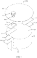
FIG. 1 is an exploded schematic structural diagram of a battery in an embodiment. -
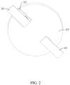
FIG. 2 is a schematic structural diagram of a cover of the battery inFIG. 1 when viewed in another direction. -
FIG. 3 is a schematic structural diagram of a battery before a tab is bent. -
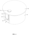
FIG. 4 is a schematic structural diagram of a battery after a tab is bent. -
FIG. 5 is a structural block diagram of an electronic apparatus in an embodiment. - Reference signs of main components:
battery 100 cell assembly 10 first tab 11 second tab 12 Side 13 end face 14 first pole 21 cover 22 first through hole 221 first adapter 30 second adapter 40 first insulator 50 through groove 51 second insulator 60 electronic apparatus 200 circuit component 201 - The following clearly describes the technical solutions in the embodiments of this application with reference to the accompanying drawings in the embodiments of this application. Apparently, the described embodiments are only some rather than all of the embodiments of this application.
- It should be noted that when a component is referred to as being "fixed to" another component, it may be directly fixed to the another component, or there may be a component in between. When a component is deemed as being "connected to" another component, it may be directly connected to the another component, or there may be a component in between. When a component is deemed as being "provided on" another component, it may be directly provided on the another component, or there may be a component in between. The terms "vertical", "horizontal", "left", "right", and other similar expressions as used herein are for illustration only.
- Unless otherwise defined, all technical and scientific terms used herein shall have the same meanings as commonly understood by those skilled in the art to which this application belongs. The terms used herein in the specification of this application are only used to describe specific embodiments, and are not intended to limit this application. The term "and/or" used herein includes any and all combinations of one or more related listed items.
- An embodiment of this application provides a battery, including a packaging case and a cell assembly, where the packaging case includes a cover, and the cell assembly is provided in the packaging case. The battery further includes a first adapter, where the first adapter is connected to the cover. The cell assembly includes a first tab, where the first tab protrudes outward from a side of the cell assembly. The first tab is electrically connected to the first adapter, and the first tab and the first adapter are bent toward an outer surface of the cell assembly.
- In the foregoing battery, a connection structure of a tab has been changed to the outside of the cell assembly by using the first adapter, and the tab and the first adapter are directly bent to the outer surface of the cell assembly, simplifying welding and bending, reducing operation difficulty, keeping the final state of the tab controllable, and reducing pulling of the tab.
- Some embodiments of this application are described in detail. In absence of conflicts, the following embodiments and features in the embodiments may be combined.
- Referring to
FIG. 1 , in one of the embodiments of this application, abattery 100 includes a packaging case and acell assembly 10. The packaging case includes acover 22, and thecell assembly 10 is provided in the packaging case. Thebattery 100 further includes afirst adapter 30, where thefirst adapter 30 is connected to thecover 22 and protrudes from thecover 22. Thecell assembly 10 includes afirst tab 11, where thefirst tab 11 protrudes outward from a side of thecell assembly 10. Thefirst tab 11 is electrically connected to thefirst adapter 30, and thefirst tab 11 and thefirst adapter 30 are bent toward an outer surface of thecell assembly 10, so that thefirst tab 11 and thefirst adapter 30 are located at aside 13 of thecell assembly 10. In this embodiment of this application, the outer surface of thecell assembly 10 is theside 13, and thefirst tab 11 and thefirst adapter 30, after being welded, are bent toward theside 13 together. - In this embodiment of this application, the
cell assembly 10 is roughly cylindrical. In other embodiments, thecell assembly 10 may be cuboid, irregular, or the like. This application is not limited thereto. Thecell assembly 10 may be a wound cell or a laminated cell, and the outermost layer of the battery cell is a negative electrode plate. - Further, the
battery 100 further includes afirst pole 21, and thecover 22 is provided with a first throughhole 221, where thefirst pole 21 is mounted in the first throughhole 221 and insulated from thecover 22, thefirst adapter 30 is electrically connected to thefirst pole 21 and thefirst tab 11, and asecond adapter 40 is electrically connected to thecover 22 and asecond tab 12, so that thefirst pole 21 becomes a positive electrode of thebattery 100 and thecover 22 becomes a negative electrode of thebattery 100. It may be understood that thefirst pole 21 may become a negative electrode of thebattery 100 and thecover 22 may become a positive electrode of thebattery 100 in other embodiments. This application is not limited thereto. - Referring to
FIG. 3 andFIG. 4 , thecover 22 is provided at anend face 14 of thecell assembly 10, thefirst tab 11 is parallel to theend face 14 of thecell assembly 10, thefirst adapter 30 is parallel to thefirst tab 11, and an end of thefirst adapter 30 protruding from thecover 22 and an end of thefirst tab 11 protruding from a side of thecell assembly 10 are connected and then bent toward theside 13 of thecell assembly 10, such that a welding position of thefirst tab 11 and thefirst adapter 30 is changed from the inside of thecover 22 to the outside of thecell assembly 10, reducing welding difficulty, simplifying bending, reducing manufacturing costs, and improving production efficiency. In addition, compared to a traditional structural design with tabs connected to the inside of thecover 22, in this application, tabs are attached to the outer surface of thecell assembly 10 by one bending, avoiding pulling of the tabs caused by motion of the packaging case, reducing manufacturing difficulty of thebattery 100, and achieving a higher battery yield rate. - Further, in a direction of the
first adapter 30 protruding from thecover 22, a length of thefirst adapter 30 is greater than a length of thefirst tab 11, and the end of thefirst adapter 30 protruding from thecover 22 is aligned with the end of thefirst tab 11 protruding from a side of thecell assembly 10. In a direction vertical to that of thefirst adapter 30 protruding from thecover 22, a width of thefirst adapter 30 is less than or equal to a width of thefirst tab 11, facilitating welding of thefirst tab 11 to thefirst adapter 30. - Referring to
FIG. 1 andFIG. 2 , in one of the embodiments of this application, thebattery 100 includes asecond adapter 40, and thecell assembly 10 further includes asecond tab 12, where thesecond adapter 40 is electrically connected to thesecond tab 12 and thecover 22. For ease of connection to thecover 22, thefirst tab 11 and thesecond tab 12 are spaced apart at theend face 14 of thecell assembly 10, helping to shorten the lengths of the tabs, thereby achieving a higher energy density of thebattery 100. The polarities of thefirst tab 11 and thesecond tab 12 are opposite. In this embodiment of this application, thefirst tab 11 is a positive tab, and thesecond tab 12 is a negative tab. Thefirst tab 11 and thesecond tab 12 are spaced apart at sides of theend face 14 of thecell assembly 10, and protrude outward from the sides of theend face 14. Thesecond adapter 40 also protrudes from thecover 22, and an end of thesecond tab 12 protruding from a side of thecell assembly 10 and an end of thesecond adapter 40 protruding from thecover 22 are welded and then bent toward the outer surface of thecell assembly 10, so that thesecond tab 12 and thesecond adapter 40 are located at the outer surface of thecell assembly 10. - In an extended embodiment, the
battery 100 further includes a second pole (not shown in the figure), with a polarity opposite to that of thefirst pole 21. Thecover 22 is provided with a second through hole (not shown in the figure), and the second pole is mounted in the second through hole and insulated from thecover 22. Thesecond adapter 40 is electrically connected to the second pole and thesecond tab 12. - In an optional embodiment, the
first adapter 30 may be electrically connected to thecover 22, and the packaging case further includes a housing (not shown in the figure), where thecell assembly 10 is provided in the housing, and the housing is insulated from thecover 22. Thesecond adapter 40 is electrically connected to thesecond tab 12 and the housing. - In one of the embodiments of this application, to prevent a short circuit caused by contact between the
first tab 11 andfirst adapter 30 and thecover 22, thebattery 100 further includes afirst insulator 50. Thefirst insulator 50 is provided between thefirst adapter 30 and thecover 22 to separate thefirst adapter 30 from thecover 22. A width of thefirst insulator 50 may be greater than or equal to that of thefirst adapter 30, and a length of thefirst insulator 50 may be greater than or equal to that of thefirst adapter 30 covered by thecover 22, to effectively prevent a short circuit caused by contact between the first adapter 30and thecover 22. Further, thefirst insulator 50 is provided with a throughgroove 51, and thefirst pole 21 runs through the throughgroove 51 and is connected to thefirst adapter 30. - Referring to
FIG. 1 ,FIG. 3 , andFIG. 4 again, in an optional embodiment, as the outer surface of thecell assembly 10 is a negative electrode and thefirst tab 11 is a positive tab, to prevent a short circuit caused by contact between thefirst tab 11 and the outer surface of thecell assembly 10, thebattery 100 further includes asecond insulator 60. Thesecond insulator 60 is roughly L-shaped, may be made of insulating hot melt adhesive, insulating double-sided adhesive, or the like, and is provided between thefirst tab 11 and the outer surface of thecell assembly 10. Specifically, thesecond insulator 60 is attached to a surface of thefirst tab 11 in a side back away from thefirst adapter 30 and theside 13 of thecell assembly 10. After thefirst tab 11 is bent, thesecond insulator 60 is sandwiched between thefirst tab 11 and theside 13 of thecell assembly 10. The width and length of thesecond insulator 60 are greater than those of thefirst tab 11, to effectively prevent direct contact between thefirst tab 11 and theside 13. As thesecond tab 12 is a negative tab, thesecond tab 12 may be directly bent and attached to a side of thecell assembly 10 after being welded to thesecond adapter 40. After thefirst tab 11 and thesecond tab 12 are bent, adhesive may be applied on theside 13 of thecell assembly 10 to fasten thefirst tab 11 and thesecond tab 12 to theside 13 of thecell assembly 10. - Referring to
FIG. 5 , one of the embodiments of this application provides anelectronic apparatus 200, including thebattery 100 in any one of the foregoing embodiments and acircuit component 201 electrically connected to thebattery 100. Optionally, thebattery 100 may be a small battery such as a button cell, and theelectronic apparatus 200 may be a small electronic product such as an earphone. - An embodiment of this application further provides a battery assembling method, for manufacturing the
battery 100 in any one or a combination of the foregoing embodiments. The battery assembling method includes: connecting thefirst adapter 30 to thecover 22 and having thefirst adapter 30 protruding from thecover 22; disposing thecover 22 at theend face 14 of thecell assembly 10, with thefirst tab 11 parallel to theend face 14 of thecell assembly 10 and protruding outward; electrically connecting an end of thefirst adapter 30 protruding from thecover 22 to an end of thefirst tab 11 protruding from thecell assembly 10; and bending thefirst adapter 30 and thefirst tab 11 toward the outer surface of thecell assembly 10, so that thefirst tab 11 and thefirst adapter 30 are located at a side of thecell assembly 10. - Further, the
first adapter 30 is electrically connected to thefirst pole 21 on thecover 22 and thefirst tab 11, and thefirst insulator 50 is provided between thefirst adapter 30 and thecover 22 to prevent a short circuit caused by contact between thefirst adapter 30 and thecover 22. Before the bending thefirst adapter 30 and thefirst tab 11 toward the outer surface of thecell assembly 10, the battery assembling method further includes: disposing thesecond insulator 60 between thefirst tab 11 and the outer surface of thecell assembly 10, to prevent a short circuit caused by contact between thefirst tab 11 and the outer surface of thecell assembly 10. Specifically, thesecond insulator 60 is attached to a surface of thefirst tab 11 in a side back away from thefirst adapter 30 and theside 13 of thecell assembly 10. After thefirst tab 11 and thefirst adapter 30 are bent, thesecond insulator 60 is sandwiched between thefirst tab 11 and theside 13 of thecell assembly 10. - In an optional embodiment, the battery assembling method further includes: connecting a
second adapter 40 to thecover 22 and having thesecond adapter 40 protruding from thecover 22; before the disposing thecover 22 at theend face 14 of thecell assembly 10, having thesecond tab 12 parallel to theend face 14 of thecell assembly 10 and protruding outward; and connecting an end of thesecond adapter 40 protruding from thecover 22 to an end of thesecond tab 12 protruding from thecell assembly 10, and bending the two ends toward the outer surface of thecell assembly 10, so that a joint between thesecond tab 12 and thesecond adapter 40 is disposed at the outer surface of thecell assembly 10. - The foregoing embodiments are merely intended to describe the technical solutions of this application, but not intended to constitute any limitation. Although this application is described in detail with reference to the foregoing preferred embodiments, persons of ordinary skill in the art should understand that modifications or equivalent replacements can be made to the technical solutions of this application, without departing from the spirit and scope of the technical solutions of this application.
Claims (13)
- A battery, comprising:a packaging case, comprising a cover; anda cell assembly, provided in the packaging case; characterized in thatthe battery further comprises a first adapter, wherein the first adapter is connected to the cover; andthe cell assembly comprises a first tab, wherein the first tab protrudes outward from a side of the cell assembly, the first tab is electrically connected to the first adapter, and the first tab and the first adapter are bent toward an outer surface of the cell assembly.
- The battery according to claim 1, characterized in that the battery further comprises a first pole, and the cover is provided with a first through hole, wherein the first pole is mounted in the first through hole and insulated from the cover, and the first adapter is electrically connected to the first pole and the first tab.
- The battery according to claim 2, characterized in that the battery comprises a second adapter, and the cell assembly further comprises a second tab, wherein the second adapter is electrically connected to the second tab and the cover, and the second tab and the second adapter are bent toward the outer surface of the cell assembly.
- The battery according to claim 2, characterized in that the battery further comprises a second pole, and the cover is provided with a second through hole, wherein the second pole is mounted in the second through hole and insulated from the cover; and
the battery comprises a second adapter, and the cell assembly further comprises a second tab, wherein the second adapter is electrically connected to the second pole and the second tab. - The battery according to claim 1, characterized in that the first adapter is electrically connected to the cover.
- The battery according to claim 5, characterized in that
the packaging case further comprises a housing, wherein the housing is insulated from the cover; and the battery comprises a second adapter, and the cell assembly further comprises a second tab, wherein the second adapter is electrically connected to the second tab and the housing. - The battery according to claim 2, characterized in that the battery further comprises a first insulator, wherein the first insulator is provided between the first adapter and the cover.
- The battery according to claim 7, characterized in that the first insulator is provided with a through groove, and the first pole runs through the through groove and is connected to the first adapter.
- The battery according to claim 1, characterized in that the battery further comprises a second insulator provided between the first tab and the outer surface of the cell assembly.
- An electronic apparatus, comprising a circuit component and a battery, characterized in that the battery is the battery according to any one of claims 1 to 9, and the circuit component is electrically connected to the battery.
- A battery assembling method for manufacturing the battery according to any one of claims 1 to 9, characterized in that the battery assembling method comprises:connecting the first adapter to the cover and having the first adapter protruding from the cover;disposing the cover at an end face of the cell assembly, with the first tab parallel to the end face of the cell assembly and protruding outward;electrically connecting an end of the first adapter protruding from the cover to an end of the first tab protruding from the cell assembly; andbending the first adapter and the first tab toward the outer surface of the cell assembly.
- The battery assembling method according to claim 11, characterized in that, before the step of bending the first adapter and the first tab toward the outer surface of the cell assembly, the battery assembling method further comprises:
disposing the second insulator between the first tab and the outer surface of the cell assembly. - The battery assembling method according to claim 11, characterized by further comprising:connecting the second adapter to the cover and having the second adapter protruding from the cover;having the second tab parallel to an end face of the cell assembly and protruding outward; andconnecting an end of the second adapter protruding from the cover to an end of the second tab protruding from the cell assembly, and bending the two ends toward the outer surface of the cell assembly.
Applications Claiming Priority (1)
| Application Number | Priority Date | Filing Date | Title |
|---|---|---|---|
| PCT/CN2020/097801 WO2021258304A1 (en) | 2020-06-23 | 2020-06-23 | Battery, electronic device, and battery assembling method |
Publications (2)
| Publication Number | Publication Date |
|---|---|
| EP4156403A1 true EP4156403A1 (en) | 2023-03-29 |
| EP4156403A4 EP4156403A4 (en) | 2023-09-06 |
Family
ID=79282708
Family Applications (1)
| Application Number | Title | Priority Date | Filing Date |
|---|---|---|---|
| EP20942058.7A Pending EP4156403A4 (en) | 2020-06-23 | 2020-06-23 | Battery, electronic device, and battery assembling method |
Country Status (4)
| Country | Link |
|---|---|
| US (1) | US20230128518A1 (en) |
| EP (1) | EP4156403A4 (en) |
| CN (1) | CN115702522B (en) |
| WO (1) | WO2021258304A1 (en) |
Family Cites Families (13)
| Publication number | Priority date | Publication date | Assignee | Title |
|---|---|---|---|---|
| JP4578002B2 (en) * | 2001-01-31 | 2010-11-10 | 三洋電機株式会社 | Welded sealing battery |
| JP2011210662A (en) * | 2010-03-30 | 2011-10-20 | Sanyo Electric Co Ltd | Laminated battery |
| US9209448B2 (en) * | 2011-09-16 | 2015-12-08 | Changs Ascending Enterprise Co., Ltd. | Conductive connection structure for secondary batteries |
| CN105702906B (en) * | 2014-11-28 | 2019-01-22 | 宁德时代新能源科技股份有限公司 | Electrochemical energy storage device |
| CN205385061U (en) * | 2016-03-18 | 2016-07-13 | 宁德时代新能源科技股份有限公司 | Secondary battery |
| JP6284248B1 (en) * | 2016-11-22 | 2018-02-28 | セイコーインスツル株式会社 | Electrochemical cell and method for producing electrochemical cell |
| EP3451415B1 (en) * | 2017-08-31 | 2020-03-25 | Samsung SDI Co., Ltd. | Secondary battery |
| CN208385543U (en) * | 2018-07-02 | 2019-01-15 | 比亚迪股份有限公司 | Single battery, battery modules, power battery and electric car |
| CN111403789B (en) * | 2019-01-02 | 2021-12-10 | 东莞新能源科技有限公司 | Electrode assembly and battery |
| CN209571433U (en) * | 2019-01-22 | 2019-11-01 | 宁德时代新能源科技股份有限公司 | Secondary battery and battery module |
| CN110459705A (en) * | 2019-09-05 | 2019-11-15 | 重庆市紫建电子有限公司 | A button battery that improves radial space utilization |
| CN113097657B (en) * | 2019-09-19 | 2024-05-17 | 宁德新能源科技有限公司 | Battery |
| CN211605201U (en) * | 2020-03-31 | 2020-09-29 | 宁德新能源科技有限公司 | Battery and powered device having the same |
-
2020
- 2020-06-23 WO PCT/CN2020/097801 patent/WO2021258304A1/en not_active Ceased
- 2020-06-23 CN CN202080102315.0A patent/CN115702522B/en active Active
- 2020-06-23 EP EP20942058.7A patent/EP4156403A4/en active Pending
-
2022
- 2022-12-23 US US18/146,010 patent/US20230128518A1/en active Pending
Also Published As
| Publication number | Publication date |
|---|---|
| CN115702522A (en) | 2023-02-14 |
| WO2021258304A1 (en) | 2021-12-30 |
| US20230128518A1 (en) | 2023-04-27 |
| EP4156403A4 (en) | 2023-09-06 |
| CN115702522B (en) | 2024-06-04 |
Similar Documents
| Publication | Publication Date | Title |
|---|---|---|
| CN113437443B (en) | Electrochemical devices and electronic devices | |
| EP4024602A1 (en) | Battery and powered apparatus provided with battery | |
| WO2020024492A1 (en) | Electrode member, electrode assembly, and secondary battery | |
| US20240234960A1 (en) | Connector, battery pack, and electrical device | |
| US20240204369A1 (en) | Battery and electronic device | |
| US20200403214A1 (en) | Battery, battery pack having the same, and electric vehicle | |
| US11749861B2 (en) | Battery box and battery module | |
| JP2014236003A (en) | Battery pack | |
| EP4228049B1 (en) | Battery and electronic device having same | |
| WO2021195926A1 (en) | Battery cell structure and battery | |
| CN112259795A (en) | Battery cell assembling method and battery cell | |
| WO2023284737A1 (en) | Battery module and electrical device | |
| WO2024119911A1 (en) | Electrochemical device and electronic device | |
| CN115377619A (en) | Battery cell with lugs at two sides, battery and assembling method | |
| CN115843394A (en) | Battery cell, battery and electric equipment | |
| EP4583215A1 (en) | Battery and electronic apparatus | |
| EP4675845A1 (en) | Battery cell, battery module and vehicle | |
| CN113661605B (en) | Electrochemical device and electronic device | |
| US20230128518A1 (en) | Battery, electronic apparatus, and battery assembling method | |
| WO2019218283A1 (en) | Battery and electronic device | |
| CN217544698U (en) | Cell and battery module having the same | |
| CN214384784U (en) | Cells and electrical devices | |
| CN218769976U (en) | Battery and electronic equipment | |
| CN219286613U (en) | Electrochemical device and electronic device | |
| US20250141056A1 (en) | Battery module and manufacturing method thereof, battery pack, and electric device |
Legal Events
| Date | Code | Title | Description |
|---|---|---|---|
| STAA | Information on the status of an ep patent application or granted ep patent |
Free format text: STATUS: THE INTERNATIONAL PUBLICATION HAS BEEN MADE |
|
| PUAI | Public reference made under article 153(3) epc to a published international application that has entered the european phase |
Free format text: ORIGINAL CODE: 0009012 |
|
| STAA | Information on the status of an ep patent application or granted ep patent |
Free format text: STATUS: REQUEST FOR EXAMINATION WAS MADE |
|
| 17P | Request for examination filed |
Effective date: 20221222 |
|
| AK | Designated contracting states |
Kind code of ref document: A1 Designated state(s): AL AT BE BG CH CY CZ DE DK EE ES FI FR GB GR HR HU IE IS IT LI LT LU LV MC MK MT NL NO PL PT RO RS SE SI SK SM TR |
|
| A4 | Supplementary search report drawn up and despatched |
Effective date: 20230808 |
|
| RIC1 | Information provided on ipc code assigned before grant |
Ipc: H01M 50/147 20210101ALI20230802BHEP Ipc: H01M 50/10 20210101ALI20230802BHEP Ipc: H01M 50/50 20210101AFI20230802BHEP |
|
| DAV | Request for validation of the european patent (deleted) | ||
| DAX | Request for extension of the european patent (deleted) |