EP4156388A1 - Battery pack housing, battery pack and electric vehicle - Google Patents
Battery pack housing, battery pack and electric vehicle Download PDFInfo
- Publication number
- EP4156388A1 EP4156388A1 EP20936964.4A EP20936964A EP4156388A1 EP 4156388 A1 EP4156388 A1 EP 4156388A1 EP 20936964 A EP20936964 A EP 20936964A EP 4156388 A1 EP4156388 A1 EP 4156388A1
- Authority
- EP
- European Patent Office
- Prior art keywords
- housing
- battery pack
- sub
- plate
- side beam
- Prior art date
- Legal status (The legal status is an assumption and is not a legal conclusion. Google has not performed a legal analysis and makes no representation as to the accuracy of the status listed.)
- Granted
Links
Images



Classifications
-
- H—ELECTRICITY
- H01—ELECTRIC ELEMENTS
- H01M—PROCESSES OR MEANS, e.g. BATTERIES, FOR THE DIRECT CONVERSION OF CHEMICAL ENERGY INTO ELECTRICAL ENERGY
- H01M50/00—Constructional details or processes of manufacture of the non-active parts of electrochemical cells other than fuel cells, e.g. hybrid cells
- H01M50/10—Primary casings; Jackets or wrappings
- H01M50/102—Primary casings; Jackets or wrappings characterised by their shape or physical structure
- H01M50/112—Monobloc comprising multiple compartments
-
- H—ELECTRICITY
- H01—ELECTRIC ELEMENTS
- H01M—PROCESSES OR MEANS, e.g. BATTERIES, FOR THE DIRECT CONVERSION OF CHEMICAL ENERGY INTO ELECTRICAL ENERGY
- H01M50/00—Constructional details or processes of manufacture of the non-active parts of electrochemical cells other than fuel cells, e.g. hybrid cells
- H01M50/20—Mountings; Secondary casings or frames; Racks, modules or packs; Suspension devices; Shock absorbers; Transport or carrying devices; Holders
- H01M50/204—Racks, modules or packs for multiple batteries or multiple cells
-
- B—PERFORMING OPERATIONS; TRANSPORTING
- B60—VEHICLES IN GENERAL
- B60L—PROPULSION OF ELECTRICALLY-PROPELLED VEHICLES; SUPPLYING ELECTRIC POWER FOR AUXILIARY EQUIPMENT OF ELECTRICALLY-PROPELLED VEHICLES; ELECTRODYNAMIC BRAKE SYSTEMS FOR VEHICLES IN GENERAL; MAGNETIC SUSPENSION OR LEVITATION FOR VEHICLES; MONITORING OPERATING VARIABLES OF ELECTRICALLY-PROPELLED VEHICLES; ELECTRIC SAFETY DEVICES FOR ELECTRICALLY-PROPELLED VEHICLES
- B60L50/00—Electric propulsion with power supplied within the vehicle
- B60L50/50—Electric propulsion with power supplied within the vehicle using propulsion power supplied by batteries or fuel cells
- B60L50/60—Electric propulsion with power supplied within the vehicle using propulsion power supplied by batteries or fuel cells using power supplied by batteries
- B60L50/64—Constructional details of batteries specially adapted for electric vehicles
-
- H—ELECTRICITY
- H01—ELECTRIC ELEMENTS
- H01M—PROCESSES OR MEANS, e.g. BATTERIES, FOR THE DIRECT CONVERSION OF CHEMICAL ENERGY INTO ELECTRICAL ENERGY
- H01M10/00—Secondary cells; Manufacture thereof
- H01M10/60—Heating or cooling; Temperature control
- H01M10/61—Types of temperature control
- H01M10/613—Cooling or keeping cold
-
- H—ELECTRICITY
- H01—ELECTRIC ELEMENTS
- H01M—PROCESSES OR MEANS, e.g. BATTERIES, FOR THE DIRECT CONVERSION OF CHEMICAL ENERGY INTO ELECTRICAL ENERGY
- H01M10/00—Secondary cells; Manufacture thereof
- H01M10/60—Heating or cooling; Temperature control
- H01M10/65—Means for temperature control structurally associated with the cells
- H01M10/655—Solid structures for heat exchange or heat conduction
- H01M10/6551—Surfaces specially adapted for heat dissipation or radiation, e.g. fins or coatings
-
- H—ELECTRICITY
- H01—ELECTRIC ELEMENTS
- H01M—PROCESSES OR MEANS, e.g. BATTERIES, FOR THE DIRECT CONVERSION OF CHEMICAL ENERGY INTO ELECTRICAL ENERGY
- H01M10/00—Secondary cells; Manufacture thereof
- H01M10/60—Heating or cooling; Temperature control
- H01M10/65—Means for temperature control structurally associated with the cells
- H01M10/655—Solid structures for heat exchange or heat conduction
- H01M10/6556—Solid parts with flow channel passages or pipes for heat exchange
-
- H—ELECTRICITY
- H01—ELECTRIC ELEMENTS
- H01M—PROCESSES OR MEANS, e.g. BATTERIES, FOR THE DIRECT CONVERSION OF CHEMICAL ENERGY INTO ELECTRICAL ENERGY
- H01M50/00—Constructional details or processes of manufacture of the non-active parts of electrochemical cells other than fuel cells, e.g. hybrid cells
- H01M50/20—Mountings; Secondary casings or frames; Racks, modules or packs; Suspension devices; Shock absorbers; Transport or carrying devices; Holders
- H01M50/233—Mountings; Secondary casings or frames; Racks, modules or packs; Suspension devices; Shock absorbers; Transport or carrying devices; Holders characterised by physical properties of casings or racks, e.g. dimensions
- H01M50/236—Hardness
-
- H—ELECTRICITY
- H01—ELECTRIC ELEMENTS
- H01M—PROCESSES OR MEANS, e.g. BATTERIES, FOR THE DIRECT CONVERSION OF CHEMICAL ENERGY INTO ELECTRICAL ENERGY
- H01M50/00—Constructional details or processes of manufacture of the non-active parts of electrochemical cells other than fuel cells, e.g. hybrid cells
- H01M50/20—Mountings; Secondary casings or frames; Racks, modules or packs; Suspension devices; Shock absorbers; Transport or carrying devices; Holders
- H01M50/233—Mountings; Secondary casings or frames; Racks, modules or packs; Suspension devices; Shock absorbers; Transport or carrying devices; Holders characterised by physical properties of casings or racks, e.g. dimensions
- H01M50/24—Mountings; Secondary casings or frames; Racks, modules or packs; Suspension devices; Shock absorbers; Transport or carrying devices; Holders characterised by physical properties of casings or racks, e.g. dimensions adapted for protecting batteries from their environment, e.g. from corrosion
-
- H—ELECTRICITY
- H01—ELECTRIC ELEMENTS
- H01M—PROCESSES OR MEANS, e.g. BATTERIES, FOR THE DIRECT CONVERSION OF CHEMICAL ENERGY INTO ELECTRICAL ENERGY
- H01M50/00—Constructional details or processes of manufacture of the non-active parts of electrochemical cells other than fuel cells, e.g. hybrid cells
- H01M50/20—Mountings; Secondary casings or frames; Racks, modules or packs; Suspension devices; Shock absorbers; Transport or carrying devices; Holders
- H01M50/233—Mountings; Secondary casings or frames; Racks, modules or packs; Suspension devices; Shock absorbers; Transport or carrying devices; Holders characterised by physical properties of casings or racks, e.g. dimensions
- H01M50/242—Mountings; Secondary casings or frames; Racks, modules or packs; Suspension devices; Shock absorbers; Transport or carrying devices; Holders characterised by physical properties of casings or racks, e.g. dimensions adapted for protecting batteries against vibrations, collision impact or swelling
-
- H—ELECTRICITY
- H01—ELECTRIC ELEMENTS
- H01M—PROCESSES OR MEANS, e.g. BATTERIES, FOR THE DIRECT CONVERSION OF CHEMICAL ENERGY INTO ELECTRICAL ENERGY
- H01M50/00—Constructional details or processes of manufacture of the non-active parts of electrochemical cells other than fuel cells, e.g. hybrid cells
- H01M50/20—Mountings; Secondary casings or frames; Racks, modules or packs; Suspension devices; Shock absorbers; Transport or carrying devices; Holders
- H01M50/249—Mountings; Secondary casings or frames; Racks, modules or packs; Suspension devices; Shock absorbers; Transport or carrying devices; Holders specially adapted for aircraft or vehicles, e.g. cars or trains
-
- H—ELECTRICITY
- H01—ELECTRIC ELEMENTS
- H01M—PROCESSES OR MEANS, e.g. BATTERIES, FOR THE DIRECT CONVERSION OF CHEMICAL ENERGY INTO ELECTRICAL ENERGY
- H01M50/00—Constructional details or processes of manufacture of the non-active parts of electrochemical cells other than fuel cells, e.g. hybrid cells
- H01M50/30—Arrangements for facilitating escape of gases
- H01M50/383—Flame arresting or ignition-preventing means
-
- H—ELECTRICITY
- H01—ELECTRIC ELEMENTS
- H01M—PROCESSES OR MEANS, e.g. BATTERIES, FOR THE DIRECT CONVERSION OF CHEMICAL ENERGY INTO ELECTRICAL ENERGY
- H01M2220/00—Batteries for particular applications
- H01M2220/20—Batteries in motive systems, e.g. vehicle, ship, plane
-
- Y—GENERAL TAGGING OF NEW TECHNOLOGICAL DEVELOPMENTS; GENERAL TAGGING OF CROSS-SECTIONAL TECHNOLOGIES SPANNING OVER SEVERAL SECTIONS OF THE IPC; TECHNICAL SUBJECTS COVERED BY FORMER USPC CROSS-REFERENCE ART COLLECTIONS [XRACs] AND DIGESTS
- Y02—TECHNOLOGIES OR APPLICATIONS FOR MITIGATION OR ADAPTATION AGAINST CLIMATE CHANGE
- Y02E—REDUCTION OF GREENHOUSE GAS [GHG] EMISSIONS, RELATED TO ENERGY GENERATION, TRANSMISSION OR DISTRIBUTION
- Y02E60/00—Enabling technologies; Technologies with a potential or indirect contribution to GHG emissions mitigation
- Y02E60/10—Energy storage using batteries
-
- Y—GENERAL TAGGING OF NEW TECHNOLOGICAL DEVELOPMENTS; GENERAL TAGGING OF CROSS-SECTIONAL TECHNOLOGIES SPANNING OVER SEVERAL SECTIONS OF THE IPC; TECHNICAL SUBJECTS COVERED BY FORMER USPC CROSS-REFERENCE ART COLLECTIONS [XRACs] AND DIGESTS
- Y02—TECHNOLOGIES OR APPLICATIONS FOR MITIGATION OR ADAPTATION AGAINST CLIMATE CHANGE
- Y02T—CLIMATE CHANGE MITIGATION TECHNOLOGIES RELATED TO TRANSPORTATION
- Y02T10/00—Road transport of goods or passengers
- Y02T10/60—Other road transportation technologies with climate change mitigation effect
- Y02T10/70—Energy storage systems for electromobility, e.g. batteries
Definitions
- the present disclosure relates to the field of batteries, and specifically to a battery pack housing, a battery pack, and an electric vehicle.
- a battery pack housing includes a tray and an upper cover connected to the tray, where the tray is usually formed by welding multiple side beams and a bottom plate. Moreover, as a main load-bearing component, the tray is generally welded with some reinforcing transverse and longitudinal beams inside the tray to ensure that the tray has a sufficient structural strength. As a result, the tray is caused to have too much components, and have a complex structure and a low space utilization rate. Moreover, the existing battery pack housing is relatively simple in structure and less versatile, which is adverse to the standardization, modularization and mass production of battery packs.
- a battery pack housing which includes a housing body, including multiple connected sub-housings, where at least one sub-housing is provided with at least one reinforcing plate therein.
- the sub-housing includes a top plate and a bottom plate arranged opposite to each other in a first direction, in which the first direction is a height direction of the housing.
- the reinforcing plate is located between the top plate and the bottom plate, the at least one reinforcing plate is connected to the top plate and the bottom plate, and the at least one reinforcing plate divides the interior of a corresponding sub-housing into multiple accommodating cavities.
- a mounting portion is provided on the housing, which is configured to be connected and fixed to an external load.
- a battery pack including a battery pack housing as described above.
- an electric vehicle including a vehicle body and a battery pack as described above, where the battery pack is fixed to the vehicle body by the mounting portion.
- the present disclosure has the following beneficial effects.
- the battery pack housing according to the present disclosure includes multiple connected sub-housings, and the number of the sub-housings can be selected according to actual needs, to increases the flexibility and versatility in the design of the battery pack, and facilitate the standardization, modularization and mass production of the battery pack.
- the reinforcing plate is located between the top plate and the bottom plate, and the reinforcing plate is connected to the top plate and the bottom plate.
- Such a design allows the reinforcing plate, the top plate and the bottom plate to form an "I"-shaped structure. This structure has high strength and rigidity, so the battery pack housing has good load-bearing capacity, impact resistance, extrusion resistance, and other performances.
- the battery pack housing according to the present disclosure has simple structure, low manufacturing cost, and high space utilization rate. Furthermore, when this battery pack is mounted on a vehicle, the structural strength of the battery pack serves as part of the structural strength of the vehicle, to improve the structural strength of the vehicle, help to meet the design requirement of lightweight of the electric vehicle, and reduce the design and manufacturing costs of the vehicle.
- orientations or positional relationships indicated by the terms “length”, “width”, “upper”, “lower”, “front”, “rear”, “left”, “right”, “vertical”, “horizontal”, “top”, “bottom”, “inner”, “outer”, etc. are the orientations or positional relationships shown in the drawings, are merely to facilitate describing the present disclosure and to simplify the description, are not intended to indicate or imply that the referenced device or element must have a particular orientation, be constructed and operated in a particular orientation, and therefore are not to be construed as limiting the present disclosure.
- first and second are used merely for the purpose of description, and shall not be construed as indicating or implying relative importance or implying a quantity of indicated technical features. Therefore, a feature restricted by “first” or “second” may explicitly indicate or implicitly include one or more features.
- “multiple” means two or more than two, unless it is specifically defined otherwise.
- connection may be a fixed connection, a detachable connection, or an integral connection; or the connection may be a mechanical connection or an electrical connection; or the connection may be a direct connection, an indirect connection through an intermediary, or internal communication between two components or interaction between two components.
- a first embodiment of the present disclosure provides a battery pack housing 100.
- the housing 100 includes a housing body 115, and the housing body 115 includes multiple connected sub-housings 101. At least one sub-housing 101 is provided with at least one reinforcing plate 200 therein.
- the sub-housing 101 includes a top plate 102 and a bottom plate 103 arranged opposite to each other in a first direction, in which the first direction is a height direction of the housing 100.
- the reinforcing plate 200 is located between the top plate 102 and the bottom plate 103, the at least one reinforcing plate 200 is connected to the top plate 102 and the bottom plate 103, and the at least one reinforcing plate 200 divides the interior of a corresponding sub-housing 101 into multiple accommodating cavities 300.
- a mounting portion 104 is provided on the housing 100, and the mounting portion 104 is configured to be connected and fixed to an external load.
- the first direction is the X direction in the figure.
- the housing 100 of a battery pack 10 includes multiple connected sub-housings 101, and the number of the sub-housings 101 can be selected according to actual needs, to increases the flexibility and versatility in the design of the battery pack 10, and facilitate the standardization, modularization and mass production of the battery pack 10.
- the reinforcing plate 200 is located between the top plate 102 and the bottom plate 103, and the reinforcing plate 200 is connected to the top plate 102 and the bottom plate 103.
- Such a design allows the reinforcing plate 200, the top plate 102 and the bottom plate 103 to form an "I"-shaped structure.
- This structure has high strength and rigidity, so the housing 100 of the battery pack 10 has good load-bearing capacity, impact resistance, extrusion resistance, and other performances. Moreover, the housing of the battery pack 10 according to the present disclosure has simple structure, low manufacturing cost, and high space utilization rate. Furthermore, when this battery pack 10 is mounted on a vehicle, the structural strength of the battery pack 10 serves as part of the structural strength of the vehicle, to improve the structural strength of the vehicle, help to meet the design requirement of lightweight of the electric vehicle, and reduce the design and manufacturing costs of the vehicle.
- a mounting portion 104 is provided on the housing 100 of the battery pack 10 according to the present disclosure.
- the housing 100 of the battery pack 10 is detachably or non-detachably and fixedly connected and fixed to an external load through the mounting portion 104 provided thereon.
- the housing 100 of the battery pack 10 needs to be fixedly connected to an external load, and thus has special requirements in terms of the impact resistance, extrusion resistance and other performance, so it cannot simply be equivalent to a casing 100 of a battery module or a cell.
- the battery pack 10 also includes at least one of a battery management system (BMS), a battery connector, a battery sampler and a battery thermal management system.
- BMS battery management system
- the reinforcing plate 200 is connected to the top plate 102 and the bottom plate 103. It can be understood that the reinforcing plate 200 may be formed integrally with the top plate 102 and the bottom plate 103; or the reinforcing plate 200, the top plate 102 and the bottom plate 103 are fabricated separately, and then connected directly or indirectly, which is not particularly limited in the present disclosure.
- the direct connection may be a situation where one end of the reinforcing plate 200 is connected to the bottom plate 103, and the opposite other end of the reinforcing plate 200 is connected to the top plate 102.
- the indirect connection may be a situation where one end of the reinforcing plate 200 is connected to the bottom plate 103 via an intermediate plate, and the opposite other end of the reinforcing plate 200 is connected to the top plate 102 via an intermediate plate.
- the at least one reinforcing plate 200 is connected to the top plate 102 and the bottom plate 103. It can be understood that the top plate 102, the bottom plate 103 and the reinforcing plate 200 are integrally formed; or one of the top plate 102 and the bottom plate 103 is integrally formed with the reinforcing plate 200, and the other is welded to the reinforcing plate 200; or one end of the reinforcing plate 200 is welded to the bottom plate 103, and the opposite other end of the reinforcing plate 200 is welded to the top plate 102; or one end of the reinforcing plate 200 is welded to the bottom plate 103, and then the opposite other end of the reinforcing plate 200 is welded to the top plate 102.
- the housing 100 further includes a first side beam 106 and a second side beam 107 arranged at two opposite sides of the housing body 115 in a second direction, where the second direction is a width direction of the housing 100 or a length direction of the housing 100.
- the second direction is the Y direction in the figure.
- the multiple sub-housings 101 are arranged in sequence along the second direction.
- the sub-housings 101 at two ends in the second direction are end sub-housings.
- One of the two end sub-housings is connected to the first side beam 106, and the other is connected to the second side beam 107.
- a first sub-housing 101 and a last sub-housing 101 in the Y direction in Fig. 4 are end sub-housings.
- the end sub-housing connected to the first side beam 106 is integrally formed with the first side beam 106
- the end sub-housing connected to the second side beam 107 is integrally formed with the second side beam 107.
- At least one of the top plate 102 and the bottom plate 103 of the end sub-housing connected to the first side beam 106 is integrally formed with the first side beam 106
- at least one of the top plate 102 and the bottom plate 103 of the end sub-housing connected to the second side beam 107 is integrally formed with the second side beam 107.
- the structure is formed by extrusion with one-piece aluminum profile.
- the end sub-housing connected to the first side beam 106 is integrally formed with the first side beam 106, and the end sub-housing connected to the second side beam 107 is directly or indirectly connected to the second side beam 107.
- the end sub-housing connected to the second side beam 107 is integrally formed with the second side beam 107, and the end sub-housing connected to the first side beam 106 is directly or indirectly connected to the first side beam 106.
- the first side beam 106 and the second side beam 107 has a cavity therein, and a partition plate 108 is provided in the cavity, where the partition plate 108 divides the cavity into multiple sub-cavities.
- a partition plate 108 is provided in the cavity, where the partition plate 108 divides the cavity into multiple sub-cavities.
- the housing 100 further includes a connecting plate 109, where the connecting plate 109 is connected between two adjacent sub-housings 101.
- the pattern of connection is not particularly limited, and may be detachable connection, for example, by a bolt or a rivet; or non-detachable connection, for example, by welding or a gluing.
- the connecting plate 109 has a cavity therein, and a partition plate 108 is provided in the cavity, where the partition plate 108 divides the cavity into multiple sub-cavities.
- a partition plate 108 is provided in the cavity, where the partition plate 108 divides the cavity into multiple sub-cavities.
- the sub-housing 101 is provided with multiple reinforcing plates 200, and the multiple reinforcing plates 200 are arranged at intervals in the second direction.
- the length of each reinforcing plate 200 extends along a third direction, and each reinforcing plate 200 is connected to the top plate 102 and the bottom plate 103, where the first direction, the second direction, and the third direction are different.
- each sub-housing 101 is provided with multiple reinforcing plates 200.
- some of the sub-housings 101 are provided with multiple reinforcing plates 200 as desired in practice.
- the first direction is the height direction of the housing 100
- the second direction is the width direction of the housing 100
- the third direction is the length direction of the housing 100
- the second direction is the length direction of the housing 100
- the third direction is the width direction of the housing 100.
- the first direction is the X direction
- the second direction is the Y direction
- the third direction is the Z direction in the figure.
- any two of the first direction, the second direction, and the third direction may also be arranged at other angles with respect to each other, for example, 80°or 85°, which is not particularly limited in the present disclosure.
- the reinforcing plate 200 is connected to the top plate 102 and the bottom plate 103. It can be understood that the reinforcing plate 200 may be formed integrally with the top plate 102 and the bottom plate 103; Alternatively, the reinforcing plate 200, the top plate 102 and the bottom plate 103 are fabricated separately, and then connected directly or indirectly, which is not particularly limited in the present disclosure.
- At least one of the top plate 102 and the bottom plate 103 is integrally formed with the reinforcing plate 200.
- Such an arrangement has simple processing process and reduced production cost, and also ensures that the housing 100 has sufficient structural strength and rigidity, to meet the requirements of the housing 100 for load-bearing capacity, impact resistance, extrusion resistance, and other performances.
- the top plate 102, the bottom plate 103 and the reinforcing plate 200 are integrally formed.
- the structure is formed by extrusion with one-piece aluminum profile.
- the bottom plate 103 and the reinforcing plate 200 are integrally formed, and then the top plate 102 is welded to the reinforcing plate 200.
- the top plate 102 and the reinforcing plate 200 are integrally formed, and then the bottom plate 103 is welded to the reinforcing plate 200.
- each reinforcing plate 200 when each reinforcing plate 200 is connected to the top plate 102 and the bottom plate 103, each reinforcing plate 200, together with the top plate 102 and the bottom plate 103, an "I"-shaped structure. Therefore, the housing 100 of the battery pack 10 has generally a honeycomb structure. This structure has high strength and rigidity, to meet the requirements of the housing 100 for load-bearing capacity, impact resistance, extrusion resistance, and other performances. Moreover, the structure of the housing 100 simple, and the space utilization rate is high.
- the structural strength of the battery pack 10 serves as part of the structural strength of the vehicle, to improve the structural strength of the vehicle, help to meet the design requirement of lightweight of the electric vehicle, and reduce the design and manufacturing costs of the vehicle.
- first side beam 106 and the second side beam 107 are provided with a mounting portion 104, and the mounting portion 104 is configured to be connected and fixed to an external load.
- the mounting portion 104 may also be provided on the top plate 102 or the bottom plate 103.
- the mounting portion 104 is a mounting hole 105 provided on the first side beam 106 and the second side beam 107.
- the mounting hole 105 is configured to extend therethrough by a fastener (such as a bolt or a rivet), to fixedly connect the battery pack 10 to an external load.
- the mounting hole 105 provided on the first side beam 106 penetrates the first side beam 106 in the first direction
- the mounting hole 105 provided on the second side beam 107 penetrates the second side beam 107 in the first direction
- the axial direction of the mounting hole 105 may also be arranged at an angle with respect to the first direction, for example 5° or 10°.
- multiple mounting holes 105 are provided, and the mounting holes 105 provided on the first side beam 106 are arranged in sequence along the length direction of the first side beam 106.
- the length direction of the first side beam 106 is parallel to the third direction.
- the mounting holes 105 provided on the second side beam 107 are arranged in sequence along the length direction of the second side beam 107.
- the length direction of the second side beam 107 is parallel to the third direction.
- the mounting portion 104 is a ring provided on the first side beam 106 and the second side beam 107.
- the ring is fixedly connected to an external load, to fixedly connect the battery pack 10 to an external load.
- the mounting portion 104 is a mounting block provided on the first side beam 106 and the second side beam 107.
- the mounting block is fixed to an external load by welding.
- the mounting block can also be fixed to the external load by gluing or engaging.
- the length of the accommodating cavity 300along the third direction is greater than 500 mm. According to some embodiments of the present disclosure, the length of the accommodating cavity 300 along the third direction is 500 mm-2500 mm.
- Such a design can accommodate more batteries or electrode core sets, to enable the battery pack 10 to meet the requirements of high capacity and high space utilization rate.
- the length of the accommodating cavity 300 along the third direction is 1000 mm-2000 mm.
- the length of the accommodating cavity 300 along the third direction is 1300 mm-2200 mm.
- the sub-housing 101 has a first end and a second end opposite to each other in the third direction, and the sub-housing 101 is provided with an opening 110 at at least one of the first end and the second.
- the housing 100 further includes an end plate 111 closing the opening 110.
- Each opening 110 corresponds to at least one end plate 111.
- the pattern of the end plate 111 sealing the opening 110 of the sub-housing 101 is not particularly limited.
- the end plate 111 is welded to the sub-housing 101 to close the opening 110 of the sub-housing 101; or the end plate 111 is bonded to the sub-housing 101 to close the opening 110 of the sub-housing 101; or the end plate 111 is riveted or screwed to the sub-housing 101, and a gasket is provided between the end plate 111 and the sub-housing 101, to close the opening 110 of the sub-housing 101.
- each opening 110 corresponds to one end plate 111 respectively.
- each opening 110 may correspond to multiple end plates 111, that is, multiple end plates 111 close one opening 110 of the sub-housing 101.
- the multiple end plates 111 located at the same end of the housing body 115 in the third direction are an integrally formed piece. That is, the multiple end plates 111 located at the first end of the housing body 115 are an integrally formed piece; or the multiple end plates 111 located at the second end of the housing body 115 are an integrally formed piece; or the multiple end plates 111 located at the first end of the housing body 115 and the multiple end plates 111 located at the second end of the housing body 115 are an integrally formed piece.
- Such an arrangement can simplify the processing of the end plate 111, and reduce the cost.
- the battery pack housing 100 is a sealed housing 100, and the atmospheric pressure in the accommodating cavity 300 is lower than the atmospheric pressure outside the housing 100.
- the atmospheric pressure in the accommodating cavity 300 is made lower than atmospheric pressure outside the housing 100 by evacuation. Therefore, moisture and other substances present in the housing 100 can be reduced, to avoid the long-term aging effect and damage of the moisture on/to the electrode core set, battery and other components in the housing 100, and improve the service life of the battery pack 10.
- the sealed housing 100 also provides a secondary sealing effect.
- the pressure in the accommodating cavity 300 is -40 KPa to -70 KPa.
- Such an arrangement can ensure the reduction of moisture, oxygen, and other substances present in the housing 100, to avoid the long-term aging effect of the moisture and oxygen on the electrode core set and various components in the housing 100, and improve the service life of the electrode core set and various components in the housing 100.
- the housing 100 is provided with a gas exhaust hole communicating with the accommodating cavity 300, via which the interior of the housing 100 is evacuated. Therefore, moisture and other substances present in the housing 100 can be reduced, to avoid the long-term aging effect and damage of the moisture on/to the battery or electrode core set and other components in the housing 100, and improve the service life of the battery pack 10.
- the housing 100 is provided with an adhesive injection hole 112 (as shown in Fig. 2 ), and each accommodating cavity 300 communicates with at least one adhesive injection hole 112 correspondingly.
- the adhesive injection hole 112 is configured to fill an adhesive into a corresponding accommodating cavity 300, to fixedly connect the electrode core set or battery arranged in the accommodating cavity 300 to the housing 100, and thus further improve the structural strength of the battery pack 10.
- the adhesive injection hole 112 is provided on the top plate 102 of the sub-housing 101.
- the adhesive injection hole 112 may also be provided on the bottom plate 103 of the sub-housing 101.
- the housing 100 is provided with an anti-explosion valve 400, and the anti-explosion valve 400 seals the adhesive injection hole 112.
- the anti-explosion valve 400 can act as a sealing cover to seal the adhesive injection hole 112, and also function to prevent explosion.
- the anti-explosion valve 400 has a weak area 403; and the anti-explosion valve 400 includes a cover 402 hermetically connected to the housing 100 and a protruding portion 401 provided on the cover 402.
- the protruding portion 401 protrudes toward a side away from the housing 100, and a weak area 403 is formed on an outer peripheral wall of the protruding portion 401.
- the weak area 403 may be a groove or a notch.
- the thickness of the weak area 403 is lower than the thickness of other parts on the anti-explosion valve 400.
- the adhesive injection hole 112 is provided on the top plate 102, and the cover 402 is hermetically connected to the top plate 102.
- the pattern of hermetical connection is not particularly limited, for example, the hermetical connection can be achieved by welding or gluing.
- the anti-explosion valve 400 includes a cover 402 and a protruding portion 401 provided on the cover body 402. An edge of the cover 402 is connected to an inner wall of the adhesive injection hole 112, and the protruding portion 401 protrudes from the cover 402 toward a side away from the electrode core set.
- the bottom plate 103 is provided with a heat dissipation fin 113.
- the heat dissipation fin 113 and the bottom plate 103 are integrally formed.
- the bottom plate 103 is formed with the heat dissipation fin 113 by integral extrusion of aluminum profile. Such an arrangement can simplify the processing process and reduce the cost.
- the bottom plate 103 is provided with a flow channel 114.
- the flow channel 114 is integrally formed on the bottom plate 103.
- the bottom plate 103 is formed with the flow channel 114 by integral extrusion of aluminum profile. Such an arrangement can simplify the processing process and reduce the cost.
- the present disclosure further provides a battery pack 10, which includes a battery pack housing 100 as described above.
- the battery pack 10 according to the present disclosure has a battery pack housing100 as described above, which increases the flexibility and versatility in the design of the battery pack 10, and facilitate the standardization, modularization and mass production of the battery pack 10.
- the battery pack housing 100 has good load-bearing capacity, impact resistance and extrusion resistance, to allow the battery pack 10 to have a high structural strength.
- the present disclosure further provides an electric vehicle 500 (see Fig. 12 ), which includes a vehicle body and a battery pack 10 mentioned above, where the battery pack 10 is fixed to the vehicle body by the mounting portion 104.
- the structural strength of the battery pack 10 serves as part of the structural strength of the vehicle, to improve the structural strength of the vehicle, help to meet the design requirement of lightweight of the electric vehicle, and reduce the design and manufacturing costs of the vehicle.
- the battery pack 10 according to the present disclosure has a relatively low height, and thus will not occupy too much space in the height of the vehicle
Landscapes
- Engineering & Computer Science (AREA)
- Chemical & Material Sciences (AREA)
- General Chemical & Material Sciences (AREA)
- Electrochemistry (AREA)
- Chemical Kinetics & Catalysis (AREA)
- Manufacturing & Machinery (AREA)
- Sustainable Energy (AREA)
- Mechanical Engineering (AREA)
- Transportation (AREA)
- Power Engineering (AREA)
- Life Sciences & Earth Sciences (AREA)
- Sustainable Development (AREA)
- Aviation & Aerospace Engineering (AREA)
- Battery Mounting, Suspending (AREA)
- Secondary Cells (AREA)
Abstract
Description
- The present disclosure is proposed on the basis of and claims priority to
Chinese Patent Application No. 202010444233.6 filed on May 22, 2020 - The present disclosure relates to the field of batteries, and specifically to a battery pack housing, a battery pack, and an electric vehicle.
- In the related art, a battery pack housing includes a tray and an upper cover connected to the tray, where the tray is usually formed by welding multiple side beams and a bottom plate. Moreover, as a main load-bearing component, the tray is generally welded with some reinforcing transverse and longitudinal beams inside the tray to ensure that the tray has a sufficient structural strength. As a result, the tray is caused to have too much components, and have a complex structure and a low space utilization rate. Moreover, the existing battery pack housing is relatively simple in structure and less versatile, which is adverse to the standardization, modularization and mass production of battery packs.
- In a first aspect of the present disclosure, a battery pack housing is provided, which includes a housing body, including multiple connected sub-housings, where at least one sub-housing is provided with at least one reinforcing plate therein.
- The sub-housing includes a top plate and a bottom plate arranged opposite to each other in a first direction, in which the first direction is a height direction of the housing. The reinforcing plate is located between the top plate and the bottom plate, the at least one reinforcing plate is connected to the top plate and the bottom plate, and the at least one reinforcing plate divides the interior of a corresponding sub-housing into multiple accommodating cavities.
- A mounting portion is provided on the housing, which is configured to be connected and fixed to an external load.
- In a second aspect of the present disclosure, a battery pack is provided, including a battery pack housing as described above.
- In a third aspect of the present disclosure, an electric vehicle is provided, including a vehicle body and a battery pack as described above, where the battery pack is fixed to the vehicle body by the mounting portion.
- The present disclosure has the following beneficial effects. The battery pack housing according to the present disclosure includes multiple connected sub-housings, and the number of the sub-housings can be selected according to actual needs, to increases the flexibility and versatility in the design of the battery pack, and facilitate the standardization, modularization and mass production of the battery pack. Moreover, in the present disclosure, the reinforcing plate is located between the top plate and the bottom plate, and the reinforcing plate is connected to the top plate and the bottom plate. Such a design allows the reinforcing plate, the top plate and the bottom plate to form an "I"-shaped structure. This structure has high strength and rigidity, so the battery pack housing has good load-bearing capacity, impact resistance, extrusion resistance, and other performances. Further, the battery pack housing according to the present disclosure has simple structure, low manufacturing cost, and high space utilization rate. Furthermore, when this battery pack is mounted on a vehicle, the structural strength of the battery pack serves as part of the structural strength of the vehicle, to improve the structural strength of the vehicle, help to meet the design requirement of lightweight of the electric vehicle, and reduce the design and manufacturing costs of the vehicle.
-
-
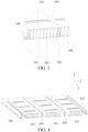
Fig. 1 is a schematic structural view of a battery pack provided in an embodiment of the present disclosure; -
Fig. 2 is a schematic structural view of a battery pack housing provided in an embodiment of the present disclosure; -
Fig. 3 is a partially enlarged view of part A inFig. 2 ; -
Fig. 4 is an exploded view of a battery pack housing provided in an embodiment of the present disclosure; -
Fig. 5 is an exploded view of a battery pack housing provided in an embodiment of the present disclosure; -
Fig. 6 is an exploded view of a battery pack housing provided in another embodiment of the present disclosure; -
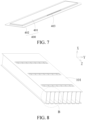
Fig. 7 is a schematic structural view of an anti-explosion valve provided in an embodiment of the present disclosure; -
Fig. 8 is a schematic structural view of a sub-housing provided in an embodiment of the present disclosure; -
Fig. 9 is a partially enlarged view of part B inFig. 8 ; -
Fig. 10 is a schematic structural view of another sub-housing provided in an embodiment of the present disclosure; -
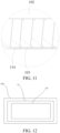
Fig. 11 is a partially enlarged view of part C inFig. 10 ; and -
Fig. 12 is a schematic structural view of an electric vehicle provided in an embodiment of the present disclosure. -
- 10. battery pack;
- 100. housing; 101. sub-housings; 102. top plate; 103. bottom plate; 104. mounting portion; 105. mounting hole; 106. first side beam; 107. second side beam; 108. partition plate; 109. connecting plate; 110. opening; 111. end plate; 112. adhesive injection hole; 113. heat dissipation fin; 114. flow channel; 115. housing body;
- 200. reinforcing plate;
- 300. accommodating cavity;
- 400. anti-explosion valve; 401. protruding portion; 402. cover; 403. weak area;
- 500. electric vehicle.
- The following descriptions are exemplary implementations of the present disclosure. It should be noted that a person of ordinary skill in the art may make certain improvements and polishing without departing from the principle of the present disclosure and the improvements and polishing shall fall within the protection scope of the present disclosure.
- In the description of the present disclosure, it should be understood that the orientations or positional relationships indicated by the terms "length", "width", "upper", "lower", "front", "rear", "left", "right", "vertical", "horizontal", "top", "bottom", "inner", "outer", etc. are the orientations or positional relationships shown in the drawings, are merely to facilitate describing the present disclosure and to simplify the description, are not intended to indicate or imply that the referenced device or element must have a particular orientation, be constructed and operated in a particular orientation, and therefore are not to be construed as limiting the present disclosure.
- In addition, terms "first" and "second" are used merely for the purpose of description, and shall not be construed as indicating or implying relative importance or implying a quantity of indicated technical features. Therefore, a feature restricted by "first" or "second" may explicitly indicate or implicitly include one or more features. In description of the present disclosure, "multiple" means two or more than two, unless it is specifically defined otherwise.
- In the present disclosure, unless otherwise explicitly specified or defined, the terms such as "mount", "install", "connect", "connection", and "fixed" should be understood in a broad sense. For example, the connection may be a fixed connection, a detachable connection, or an integral connection; or the connection may be a mechanical connection or an electrical connection; or the connection may be a direct connection, an indirect connection through an intermediary, or internal communication between two components or interaction between two components. A person of ordinary skill in the art may understand the specific meanings of the foregoing terms in the present disclosure according to specific situations.
- Referring to
Figs. 1 to 4 , a first embodiment of the present disclosure provides abattery pack housing 100. Thehousing 100 includes ahousing body 115, and thehousing body 115 includes multiple connected sub-housings 101. At least onesub-housing 101 is provided with at least one reinforcingplate 200 therein. The sub-housing 101 includes atop plate 102 and abottom plate 103 arranged opposite to each other in a first direction, in which the first direction is a height direction of thehousing 100. The reinforcingplate 200 is located between thetop plate 102 and thebottom plate 103, the at least one reinforcingplate 200 is connected to thetop plate 102 and thebottom plate 103, and the at least one reinforcingplate 200 divides the interior of acorresponding sub-housing 101 into multiple accommodatingcavities 300. A mountingportion 104 is provided on thehousing 100, and the mountingportion 104 is configured to be connected and fixed to an external load. The first direction is the X direction in the figure. - The
housing 100 of abattery pack 10 according to the present disclosure includes multiple connectedsub-housings 101, and the number of the sub-housings 101 can be selected according to actual needs, to increases the flexibility and versatility in the design of thebattery pack 10, and facilitate the standardization, modularization and mass production of thebattery pack 10. Moreover, in the present disclosure, the reinforcingplate 200 is located between thetop plate 102 and thebottom plate 103, and the reinforcingplate 200 is connected to thetop plate 102 and thebottom plate 103. Such a design allows the reinforcingplate 200, thetop plate 102 and thebottom plate 103 to form an "I"-shaped structure. This structure has high strength and rigidity, so thehousing 100 of thebattery pack 10 has good load-bearing capacity, impact resistance, extrusion resistance, and other performances. Moreover, the housing of thebattery pack 10 according to the present disclosure has simple structure, low manufacturing cost, and high space utilization rate. Furthermore, when thisbattery pack 10 is mounted on a vehicle, the structural strength of thebattery pack 10 serves as part of the structural strength of the vehicle, to improve the structural strength of the vehicle, help to meet the design requirement of lightweight of the electric vehicle, and reduce the design and manufacturing costs of the vehicle. - It should be noted that a mounting
portion 104 is provided on thehousing 100 of thebattery pack 10 according to the present disclosure. Thehousing 100 of thebattery pack 10 is detachably or non-detachably and fixedly connected and fixed to an external load through the mountingportion 104 provided thereon. Generally, thehousing 100 of thebattery pack 10 needs to be fixedly connected to an external load, and thus has special requirements in terms of the impact resistance, extrusion resistance and other performance, so it cannot simply be equivalent to acasing 100 of a battery module or a cell. Generally, thebattery pack 10 also includes at least one of a battery management system (BMS), a battery connector, a battery sampler and a battery thermal management system. - In addition, the reinforcing
plate 200 is connected to thetop plate 102 and thebottom plate 103. It can be understood that the reinforcingplate 200 may be formed integrally with thetop plate 102 and thebottom plate 103; or the reinforcingplate 200, thetop plate 102 and thebottom plate 103 are fabricated separately, and then connected directly or indirectly, which is not particularly limited in the present disclosure. The direct connection may be a situation where one end of the reinforcingplate 200 is connected to thebottom plate 103, and the opposite other end of the reinforcingplate 200 is connected to thetop plate 102. The indirect connection may be a situation where one end of the reinforcingplate 200 is connected to thebottom plate 103 via an intermediate plate, and the opposite other end of the reinforcingplate 200 is connected to thetop plate 102 via an intermediate plate. - In some embodiments, the at least one reinforcing
plate 200 is connected to thetop plate 102 and thebottom plate 103. It can be understood that thetop plate 102, thebottom plate 103 and the reinforcingplate 200 are integrally formed; or one of thetop plate 102 and thebottom plate 103 is integrally formed with the reinforcingplate 200, and the other is welded to the reinforcingplate 200; or one end of the reinforcingplate 200 is welded to thebottom plate 103, and the opposite other end of the reinforcingplate 200 is welded to thetop plate 102; or one end of the reinforcingplate 200 is welded to thebottom plate 103, and then the opposite other end of the reinforcingplate 200 is welded to thetop plate 102. - In an embodiment, as shown in
Fig. 1 and Fig. 2 , thehousing 100 further includes afirst side beam 106 and asecond side beam 107 arranged at two opposite sides of thehousing body 115 in a second direction, where the second direction is a width direction of thehousing 100 or a length direction of thehousing 100. The second direction is the Y direction in the figure. - In an embodiment, as shown in
Fig. 4 , themultiple sub-housings 101 are arranged in sequence along the second direction. Among themultiple sub-housings 101, the sub-housings 101 at two ends in the second direction are end sub-housings. One of the two end sub-housings is connected to thefirst side beam 106, and the other is connected to thesecond side beam 107. Afirst sub-housing 101 and alast sub-housing 101 in the Y direction inFig. 4 are end sub-housings. - According to some embodiments of the present disclosure, the end sub-housing connected to the
first side beam 106 is integrally formed with thefirst side beam 106, and the end sub-housing connected to thesecond side beam 107 is integrally formed with thesecond side beam 107. As such, this structure can not only simplify the processing process and reduce the cost, but also is ensured to have sufficient structural strength. - In some embodiments, at least one of the
top plate 102 and thebottom plate 103 of the end sub-housing connected to thefirst side beam 106 is integrally formed with thefirst side beam 106, and at least one of thetop plate 102 and thebottom plate 103 of the end sub-housing connected to thesecond side beam 107 is integrally formed with thesecond side beam 107. For example, the structure is formed by extrusion with one-piece aluminum profile. - However, in other embodiments, the end sub-housing connected to the
first side beam 106 is integrally formed with thefirst side beam 106, and the end sub-housing connected to thesecond side beam 107 is directly or indirectly connected to thesecond side beam 107. Alternatively, the end sub-housing connected to thesecond side beam 107 is integrally formed with thesecond side beam 107, and the end sub-housing connected to thefirst side beam 106 is directly or indirectly connected to thefirst side beam 106. - In an embodiment, as shown in
Figs. 2 to 4 , thefirst side beam 106 and thesecond side beam 107 has a cavity therein, and apartition plate 108 is provided in the cavity, where thepartition plate 108 divides the cavity into multiple sub-cavities. Such an arrangement can ensure that thefirst side beam 106 and thesecond side beam 107 have a certain structural strength, to improve the impact resistance and anti-extrusion strength of thebattery pack 10. However, in other embodiments, thefirst side beam 106 or thesecond side beam 107 has a cavity therein. - In an embodiment, as shown in
Figs. 2 to 4 , thehousing 100 further includes a connectingplate 109, where the connectingplate 109 is connected between twoadjacent sub-housings 101. In the present disclosure, the pattern of connection is not particularly limited, and may be detachable connection, for example, by a bolt or a rivet; or non-detachable connection, for example, by welding or a gluing. - In an embodiment, as shown in
Fig. 3 , the connectingplate 109 has a cavity therein, and apartition plate 108 is provided in the cavity, where thepartition plate 108 divides the cavity into multiple sub-cavities. Such an arrangement can increase the structural strength of the connectingplate 109, thereby improving the reliability of connection between two sub-housings 101. - In an embodiment, as shown in
Fig. 2 andFig. 3 , the sub-housing 101 is provided with multiple reinforcingplates 200, and the multiple reinforcingplates 200 are arranged at intervals in the second direction. The length of each reinforcingplate 200 extends along a third direction, and each reinforcingplate 200 is connected to thetop plate 102 and thebottom plate 103, where the first direction, the second direction, and the third direction are different. In this embodiment, each sub-housing 101 is provided with multiple reinforcingplates 200. Definitely, in other embodiments, some of the sub-housings 101 are provided with multiple reinforcingplates 200 as desired in practice. - In the present disclosure, the first direction is the height direction of the
housing 100, the second direction is the width direction of thehousing 100, and the third direction is the length direction of thehousing 100. Alternatively, the second direction is the length direction of thehousing 100, and the third direction is the width direction of thehousing 100. The first direction is the X direction, the second direction is the Y direction, and the third direction is the Z direction in the figure. - However, in other embodiments, any two of the first direction, the second direction, and the third direction may also be arranged at other angles with respect to each other, for example, 80°or 85°, which is not particularly limited in the present disclosure.
- It should be noted that the reinforcing
plate 200 is connected to thetop plate 102 and thebottom plate 103. It can be understood that the reinforcingplate 200 may be formed integrally with thetop plate 102 and thebottom plate 103; Alternatively, the reinforcingplate 200, thetop plate 102 and thebottom plate 103 are fabricated separately, and then connected directly or indirectly, which is not particularly limited in the present disclosure. - In some embodiments, at least one of the
top plate 102 and thebottom plate 103 is integrally formed with the reinforcingplate 200. Such an arrangement has simple processing process and reduced production cost, and also ensures that thehousing 100 has sufficient structural strength and rigidity, to meet the requirements of thehousing 100 for load-bearing capacity, impact resistance, extrusion resistance, and other performances. - Specifically, the
top plate 102, thebottom plate 103 and the reinforcingplate 200 are integrally formed. For example, the structure is formed by extrusion with one-piece aluminum profile. In another embodiment, thebottom plate 103 and the reinforcingplate 200 are integrally formed, and then thetop plate 102 is welded to the reinforcingplate 200. Alternatively, thetop plate 102 and the reinforcingplate 200 are integrally formed, and then thebottom plate 103 is welded to the reinforcingplate 200. - It can be understood that when each reinforcing
plate 200 is connected to thetop plate 102 and thebottom plate 103, each reinforcingplate 200, together with thetop plate 102 and thebottom plate 103, an "I"-shaped structure. Therefore, thehousing 100 of thebattery pack 10 has generally a honeycomb structure. This structure has high strength and rigidity, to meet the requirements of thehousing 100 for load-bearing capacity, impact resistance, extrusion resistance, and other performances. Moreover, the structure of thehousing 100 simple, and the space utilization rate is high. When thisbattery pack 10 is mounted on a vehicle, the structural strength of thebattery pack 10 serves as part of the structural strength of the vehicle, to improve the structural strength of the vehicle, help to meet the design requirement of lightweight of the electric vehicle, and reduce the design and manufacturing costs of the vehicle. - In a further embodiment, the
first side beam 106 and thesecond side beam 107 are provided with a mountingportion 104, and the mountingportion 104 is configured to be connected and fixed to an external load. - Definitely, in other embodiments, the mounting
portion 104 may also be provided on thetop plate 102 or thebottom plate 103. - In an embodiment, as shown in
Fig. 1 and Fig. 2 , the mountingportion 104 is a mountinghole 105 provided on thefirst side beam 106 and thesecond side beam 107. The mountinghole 105 is configured to extend therethrough by a fastener (such as a bolt or a rivet), to fixedly connect thebattery pack 10 to an external load. - In some embodiments, the mounting
hole 105 provided on thefirst side beam 106 penetrates thefirst side beam 106 in the first direction, and the mountinghole 105 provided on thesecond side beam 107 penetrates thesecond side beam 107 in the first direction. However, the axial direction of the mountinghole 105 may also be arranged at an angle with respect to the first direction, for example 5° or 10°. - According to some embodiments of the present disclosure, multiple mounting
holes 105 are provided, and the mountingholes 105 provided on thefirst side beam 106 are arranged in sequence along the length direction of thefirst side beam 106. The length direction of thefirst side beam 106 is parallel to the third direction. - Similarly, the mounting
holes 105 provided on thesecond side beam 107 are arranged in sequence along the length direction of thesecond side beam 107. The length direction of thesecond side beam 107 is parallel to the third direction. - Definitely, in another embodiment, the mounting
portion 104 is a ring provided on thefirst side beam 106 and thesecond side beam 107. The ring is fixedly connected to an external load, to fixedly connect thebattery pack 10 to an external load. - However, in another embodiment, the mounting
portion 104 is a mounting block provided on thefirst side beam 106 and thesecond side beam 107. The mounting block is fixed to an external load by welding. Definitely, the mounting block can also be fixed to the external load by gluing or engaging. - In an embodiment, the length of the accommodating cavity 300along the third direction is greater than 500 mm. According to some embodiments of the present disclosure, the length of the
accommodating cavity 300 along the third direction is 500 mm-2500 mm. Such a design can accommodate more batteries or electrode core sets, to enable thebattery pack 10 to meet the requirements of high capacity and high space utilization rate. - According to some embodiments of the present disclosure, the length of the
accommodating cavity 300 along the third direction is 1000 mm-2000 mm. - According to some embodiments of the present disclosure, the length of the
accommodating cavity 300 along the third direction is 1300 mm-2200 mm. - In some embodiments, as shown in
Fig. 2 ,Fig. 5 and Fig. 6 , the sub-housing 101 has a first end and a second end opposite to each other in the third direction, and the sub-housing 101 is provided with anopening 110 at at least one of the first end and the second. Thehousing 100 further includes anend plate 111 closing theopening 110. Eachopening 110 corresponds to at least oneend plate 111. Through such an arrangement, only theend plate 111 corresponding to theopening 110 of the sub-housings 101 is needed to be removed in case of replacement or maintenance, so as to simplify the operation. - The pattern of the
end plate 111 sealing theopening 110 of the sub-housing 101 is not particularly limited. For example, theend plate 111 is welded to the sub-housing 101 to close theopening 110 of the sub-housing 101; or theend plate 111 is bonded to the sub-housing 101 to close theopening 110 of the sub-housing 101; or theend plate 111 is riveted or screwed to the sub-housing 101, and a gasket is provided between theend plate 111 and the sub-housing 101, to close theopening 110 of the sub-housing 101. - In this embodiment, both the first end and the second end of each sub-housing 101 is provided with an
opening 110, and eachopening 110 corresponds to oneend plate 111 respectively. Definitely, in other embodiments, each opening 110 may correspond tomultiple end plates 111, that is,multiple end plates 111 close oneopening 110 of the sub-housing 101. - According to some embodiments of the present disclosure, as shown in
Fig. 2 andFig. 5 , themultiple end plates 111 located at the same end of thehousing body 115 in the third direction are an integrally formed piece. That is, themultiple end plates 111 located at the first end of thehousing body 115 are an integrally formed piece; or themultiple end plates 111 located at the second end of thehousing body 115 are an integrally formed piece; or themultiple end plates 111 located at the first end of thehousing body 115 and themultiple end plates 111 located at the second end of thehousing body 115 are an integrally formed piece. Such an arrangement can simplify the processing of theend plate 111, and reduce the cost. - In some embodiments, the
battery pack housing 100 is a sealedhousing 100, and the atmospheric pressure in theaccommodating cavity 300 is lower than the atmospheric pressure outside thehousing 100. Through such an arrangement, the atmospheric pressure in theaccommodating cavity 300 is made lower than atmospheric pressure outside thehousing 100 by evacuation. Therefore, moisture and other substances present in thehousing 100 can be reduced, to avoid the long-term aging effect and damage of the moisture on/to the electrode core set, battery and other components in thehousing 100, and improve the service life of thebattery pack 10. Furthermore, the sealedhousing 100 also provides a secondary sealing effect. - In an embodiment, the pressure in the
accommodating cavity 300 is -40 KPa to -70 KPa. Such an arrangement can ensure the reduction of moisture, oxygen, and other substances present in thehousing 100, to avoid the long-term aging effect of the moisture and oxygen on the electrode core set and various components in thehousing 100, and improve the service life of the electrode core set and various components in thehousing 100. - In an embodiment, the
housing 100 is provided with a gas exhaust hole communicating with theaccommodating cavity 300, via which the interior of thehousing 100 is evacuated. Therefore, moisture and other substances present in thehousing 100 can be reduced, to avoid the long-term aging effect and damage of the moisture on/to the battery or electrode core set and other components in thehousing 100, and improve the service life of thebattery pack 10. - In some embodiments, the
housing 100 is provided with an adhesive injection hole 112 (as shown inFig. 2 ), and eachaccommodating cavity 300 communicates with at least oneadhesive injection hole 112 correspondingly. Theadhesive injection hole 112 is configured to fill an adhesive into a correspondingaccommodating cavity 300, to fixedly connect the electrode core set or battery arranged in theaccommodating cavity 300 to thehousing 100, and thus further improve the structural strength of thebattery pack 10. In this embodiment, theadhesive injection hole 112 is provided on thetop plate 102 of the sub-housing 101. Definitely, in other embodiments, theadhesive injection hole 112 may also be provided on thebottom plate 103 of the sub-housing 101. - In some embodiments, as shown in
Fig. 1 and Fig. 2 , thehousing 100 is provided with ananti-explosion valve 400, and theanti-explosion valve 400 seals theadhesive injection hole 112. As such, theanti-explosion valve 400 can act as a sealing cover to seal theadhesive injection hole 112, and also function to prevent explosion. - In some embodiments, as shown in
Fig. 7 , theanti-explosion valve 400 has aweak area 403; and theanti-explosion valve 400 includes acover 402 hermetically connected to thehousing 100 and a protrudingportion 401 provided on thecover 402. The protrudingportion 401 protrudes toward a side away from thehousing 100, and aweak area 403 is formed on an outer peripheral wall of the protrudingportion 401. As such, when the electrode core set inbattery pack 10 works abnormally and causes excessive gas production, the gas pressure will break theweak area 403 of theanti-explosion valve 400, to avoid the occurrence of safety incidents of thebattery pack 10. - It should be noted that the
weak area 403 may be a groove or a notch. Alternatively, the thickness of theweak area 403 is lower than the thickness of other parts on theanti-explosion valve 400. - According to some embodiments of the present disclosure, the
adhesive injection hole 112 is provided on thetop plate 102, and thecover 402 is hermetically connected to thetop plate 102. The pattern of hermetical connection is not particularly limited, for example, the hermetical connection can be achieved by welding or gluing. - In some embodiments, the
anti-explosion valve 400 includes acover 402 and a protrudingportion 401 provided on thecover body 402. An edge of thecover 402 is connected to an inner wall of theadhesive injection hole 112, and the protrudingportion 401 protrudes from thecover 402 toward a side away from the electrode core set. - In some embodiments, as shown in
Fig. 8 andFig. 9 , thebottom plate 103 is provided with aheat dissipation fin 113. According to some embodiments of the present disclosure, theheat dissipation fin 113 and thebottom plate 103 are integrally formed. For example, thebottom plate 103 is formed with theheat dissipation fin 113 by integral extrusion of aluminum profile. Such an arrangement can simplify the processing process and reduce the cost. - In some embodiments, as shown in
Fig. 10 andFig. 11 , thebottom plate 103 is provided with aflow channel 114. According to some embodiments of the present disclosure, theflow channel 114 is integrally formed on thebottom plate 103. For example, thebottom plate 103 is formed with theflow channel 114 by integral extrusion of aluminum profile. Such an arrangement can simplify the processing process and reduce the cost. - Moreover, the present disclosure further provides a
battery pack 10, which includes abattery pack housing 100 as described above. Thebattery pack 10 according to the present disclosure has a battery pack housing100 as described above, which increases the flexibility and versatility in the design of thebattery pack 10, and facilitate the standardization, modularization and mass production of thebattery pack 10. Moreover, thebattery pack housing 100 has good load-bearing capacity, impact resistance and extrusion resistance, to allow thebattery pack 10 to have a high structural strength. - In another aspect, the present disclosure further provides an electric vehicle 500 (see
Fig. 12 ), which includes a vehicle body and abattery pack 10 mentioned above, where thebattery pack 10 is fixed to the vehicle body by the mountingportion 104. In theelectric vehicle 500 provided in the present disclosure, when thisbattery pack 10 is mounted on a vehicle, the structural strength of thebattery pack 10 serves as part of the structural strength of the vehicle, to improve the structural strength of the vehicle, help to meet the design requirement of lightweight of the electric vehicle, and reduce the design and manufacturing costs of the vehicle. In addition, thebattery pack 10 according to the present disclosure has a relatively low height, and thus will not occupy too much space in the height of the vehicle - The foregoing embodiments are only several implementations of the present disclosure and are described in detail, but cannot be understood as limiting the patent scope of the present disclosure. It should be noted that a person of ordinary skill in the art may further make several variations and improvements without departing from the idea of the present disclosure, and the variations and improvements all fall within the protection scope of the present disclosure. Therefore, the patent protection scope of the present disclosure shall be subject to the appended claims.
Claims (20)
- A battery pack housing, comprising a housing body, wherein the housing body comprises a plurality of connected sub-housings, and at least one sub-housing is provided with at least one reinforcing plate therein;the sub-housing comprises a top plate and a bottom plate arranged opposite to each other in a first direction, in which the first direction is a height direction of the housing, the reinforcing plate is located between the top plate and the bottom plate, the at least one reinforcing plate is connected to the top plate and the bottom plate, and the at least one reinforcing plate divides the interior of a corresponding sub-housing into a plurality of accommodating cavities; anda mounting portion is provided on the housing, which is configured to be connected and fixed to an external load.
- The battery pack housing according to claim 1, further comprising a first side beam and a second side beam arranged at two opposite sides of the housing body in a second direction, wherein the second direction is a width direction of the housing or a length direction of the housing.
- The battery pack housing according to claim 2, wherein the plurality of sub-housings are arranged in sequence along the second direction, among the plurality of sub-housings, the sub-housings at two ends in the second direction are end sub-housings, one of the two end sub-housings is connected to the first side beam, and the other is connected to the second side beam.
- The battery pack housing according to claim 3, wherein the end sub-housing connected to the first side beam is integrally formed with the first side beam; or the end sub-housing connected to the second side beam is integrally formed with the second side beam; or the end sub-housing connected to the first side beam is integrally formed with the first side beam and the end sub-housing connected to the second side beam is integrally formed with the second side beam.
- The battery pack housing according to claim 2, wherein at least one of the first side beam and the second side beam has a cavity therein, a partition plate is provided in the cavity, and the partition plate divides the cavity into a plurality of sub-cavities.
- The battery pack housing according to any one of claims 1 to 5, wherein the housing body further comprises a connecting plate, connected between two adjacent sub-housings.
- The battery pack housing according to claim 6, wherein the connecting plate has a cavity therein, a partition plate is provided in the cavity, and the partition plate divides the cavity into a plurality of sub-cavities.
- The battery pack housing according to claim 1, wherein a plurality of reinforcing plates are provided in the sub-housing, the plurality of reinforcing plates are arranged at intervals in the second direction, the length of each reinforcing plate extends along a third direction, and each reinforcing plate is connected to the top plate and the bottom plate, in which the second direction is the width direction of the housing, and the third direction is the length direction of the housing; or the second direction is the length direction of the housing, and the third direction is the width direction of the housing.
- The battery pack housing according to claim 8, wherein at least one of the top plate and the bottom plate is integrally formed with the reinforcing plate.
- The battery pack housing according to claim 1, wherein the length of the accommodating cavity along the third direction is greater than 500 mm, and the third direction is the length direction of the housing or the width direction of the housing.
- The battery pack housing according to claim 1, wherein the sub-housing has a first end and a second end opposite to each other in the third direction, and the sub-housing is provided with an opening at at least one of the first end and the second end; and the housing further comprises an end plate closing the opening, and each opening corresponds to at least one end plate, in which the third direction is the length direction of the housing or the width direction of the housing.
- The battery pack housing according to claim 11, wherein a plurality of end plates located at the same end of the housing body in the third direction are an integrally formed piece.
- The battery pack housing according to claim 1, wherein the housing is provided with an adhesive injection hole, and each accommodating cavity communicates with at least one adhesive injection hole correspondingly.
- The battery pack housing according to claim 13, wherein the housing is provided with an anti-explosion valve, and the anti-explosion valve seals the adhesive injection hole.
- The battery pack housing according to claim 14, wherein the anti-explosion valve has a weak area; and the anti-explosion valve comprises a cover hermetically connected to the housing and a protruding portion provided on the cover, the protruding portion protrudes toward a side away from the housing, and the weak area is formed on an outer peripheral wall of the protruding portion.
- The battery pack housing according to claim 1, wherein the bottom plate is provided with a flow channel communicating with the exterior.
- The battery pack housing according to claim 1, wherein the bottom plate is provided with a heat dissipation fin.
- The battery pack housing according to claim 1, further comprising a first side beam and a second side beam arranged at two opposite sides of the housing body in the second direction;a plurality of reinforcing plates are provided in each sub-housing, the plurality of reinforcing plates are arranged at intervals in the second direction, the length of each reinforcing plate extends along the third direction, and each reinforcing plate is connected to the top plate and the bottom plate; and at least one of the top plate and the bottom plate is integrally formed with the reinforcing plate;the sub-housing has a first end and a second end opposite to each other in the third direction, the sub-housing is provided with an opening at both the first end and the second end, the housing further comprises an end plate closing the opening, and each opening corresponds to at least one end plate, in whichthe second direction is the width direction of the housing, and the third direction is the length direction of the housing; or the second direction is the length direction of the housing, and the third direction is the width direction of the housing.
- A battery pack, comprising a battery pack housing according to any one of claims 1 to 18.
- An electric vehicle, comprising a vehicle body and a battery pack according to claim 19, wherein the battery pack is fixed to the vehicle body by the mounting portion.
Applications Claiming Priority (2)
| Application Number | Priority Date | Filing Date | Title |
|---|---|---|---|
| CN202010444233.6A CN113782899B (en) | 2020-05-22 | 2020-05-22 | Battery pack shell, battery pack and electric vehicle |
| PCT/CN2020/128117 WO2021232705A1 (en) | 2020-05-22 | 2020-11-11 | Battery pack housing, battery pack and electric vehicle |
Publications (3)
| Publication Number | Publication Date |
|---|---|
| EP4156388A1 true EP4156388A1 (en) | 2023-03-29 |
| EP4156388A4 EP4156388A4 (en) | 2024-09-04 |
| EP4156388B1 EP4156388B1 (en) | 2025-12-31 |
Family
ID=78708904
Family Applications (1)
| Application Number | Title | Priority Date | Filing Date |
|---|---|---|---|
| EP20936964.4A Active EP4156388B1 (en) | 2020-05-22 | 2020-11-11 | BATTERY PACK HOUSING, BATTERY PACK AND ELECTRIC VEHICLE |
Country Status (6)
| Country | Link |
|---|---|
| US (1) | US20230082924A1 (en) |
| EP (1) | EP4156388B1 (en) |
| JP (1) | JP7451766B2 (en) |
| KR (1) | KR102859692B1 (en) |
| CN (1) | CN113782899B (en) |
| WO (1) | WO2021232705A1 (en) |
Families Citing this family (5)
| Publication number | Priority date | Publication date | Assignee | Title |
|---|---|---|---|---|
| DE102021129316A1 (en) * | 2021-11-11 | 2023-05-11 | Dr. Ing. H.C. F. Porsche Aktiengesellschaft | Battery module housing for accommodating at least one cell stack for use in a motor vehicle |
| CN115956321B (en) * | 2022-01-13 | 2024-01-12 | 宁德时代新能源科技股份有限公司 | Battery, electric device, method and equipment for preparing battery |
| CN117125141A (en) * | 2022-05-20 | 2023-11-28 | 比亚迪股份有限公司 | Frames and vehicles having the same |
| CN116454513B (en) * | 2023-04-28 | 2026-04-14 | 蜂巢能源科技(无锡)有限公司 | Battery pack lower box body and battery pack |
| WO2025078023A1 (en) * | 2023-10-13 | 2025-04-17 | Robert Bosch Gesellschaft mit beschränkter Haftung | Electrochemical cell stack with spatter trap |
Family Cites Families (27)
| Publication number | Priority date | Publication date | Assignee | Title |
|---|---|---|---|---|
| JP5705972B2 (en) | 2011-04-12 | 2015-04-22 | 日立オートモティブシステムズ株式会社 | Cell block |
| CN202593253U (en) | 2012-03-20 | 2012-12-12 | 苏州益茂电动客车有限公司 | Fast battery box for pure electric bus |
| US10096813B2 (en) * | 2013-11-15 | 2018-10-09 | Saft Groupe Sa | Battery design with bussing integral to battery assembly |
| CN107667442A (en) * | 2015-05-06 | 2018-02-06 | A123系统有限责任公司 | Battery crush protection system |
| US10686166B2 (en) * | 2016-02-05 | 2020-06-16 | Ford Global Technologies, Llc | Multiple cell integrated casings |
| EP3273500B1 (en) * | 2016-07-21 | 2018-09-12 | Samsung SDI Co., Ltd. | Battery system |
| US10027001B2 (en) * | 2016-09-07 | 2018-07-17 | Thunder Power New Energy Vehicle Development Company Limited | Battery system |
| CN206225433U (en) * | 2016-11-14 | 2017-06-06 | 武汉天达汇能能源系统有限公司 | A kind of monoblock type battery case suitable for pure electronic logistic car power-supply system |
| KR101928072B1 (en) * | 2016-12-30 | 2018-12-11 | 주식회사 유라코퍼레이션 | Hinge structure of battery cell module |
| KR102162968B1 (en) * | 2017-04-07 | 2020-10-07 | 주식회사 엘지화학 | Battery Pack with extendible battery module |
| DE102017206988A1 (en) * | 2017-04-26 | 2018-10-31 | Mahle Lnternational Gmbh | accumulator |
| US11376941B2 (en) * | 2017-05-05 | 2022-07-05 | Mubea Carbo Tech Gmbh | Electric vehicle battery cooling structure |
| CN109428021B (en) * | 2017-08-31 | 2024-04-02 | 宁德时代新能源科技股份有限公司 | Frame and battery module |
| DE102017127807B4 (en) * | 2017-11-24 | 2019-06-27 | Dr. Ing. H.C. F. Porsche Aktiengesellschaft | Battery device for an at least partially electrically operated motor vehicle |
| IT201800002774A1 (en) * | 2018-02-16 | 2019-08-16 | Ferrari Spa | VEHICLE BATTERY PACK |
| CN207818635U (en) * | 2018-03-12 | 2018-09-04 | 宁德时代新能源科技股份有限公司 | a battery pack |
| US12148903B2 (en) * | 2018-05-24 | 2024-11-19 | Mubea Carbo Tech Gmbh | Battery case |
| CN209461508U (en) * | 2018-12-28 | 2019-10-01 | 蜂巢能源科技有限公司 | Side beam for battery pack |
| CN110190211B (en) * | 2018-12-29 | 2020-03-31 | 比亚迪股份有限公司 | Battery tray, power battery package and vehicle |
| US12230820B2 (en) * | 2019-01-09 | 2025-02-18 | Byd Company Limited | Power battery pack and electric vehicle |
| CN111106279B (en) * | 2019-08-02 | 2022-11-08 | 宁德时代新能源科技股份有限公司 | Battery pack |
| CN111106282B (en) * | 2019-08-27 | 2021-06-11 | 宁德时代新能源科技股份有限公司 | Battery pack |
| CN110911604B (en) * | 2019-12-03 | 2021-06-08 | 安徽江淮汽车集团股份有限公司 | A power battery pack |
| CN111048868B (en) * | 2019-12-25 | 2022-01-28 | 中国第一汽车股份有限公司 | Battery monomer group and battery module |
| CN111293253B (en) * | 2020-04-24 | 2020-10-23 | 比亚迪股份有限公司 | Battery packs and electric vehicles |
| CN111312964B (en) * | 2020-04-24 | 2022-01-07 | 比亚迪股份有限公司 | Battery pack and electric vehicle |
| CN210984839U (en) * | 2020-04-24 | 2020-07-10 | 比亚迪股份有限公司 | A battery pack case, battery pack and electric vehicle |
-
2020
- 2020-05-22 CN CN202010444233.6A patent/CN113782899B/en active Active
- 2020-11-11 KR KR1020227044780A patent/KR102859692B1/en active Active
- 2020-11-11 JP JP2022571135A patent/JP7451766B2/en active Active
- 2020-11-11 EP EP20936964.4A patent/EP4156388B1/en active Active
- 2020-11-11 WO PCT/CN2020/128117 patent/WO2021232705A1/en not_active Ceased
-
2022
- 2022-11-17 US US17/989,608 patent/US20230082924A1/en active Pending
Also Published As
| Publication number | Publication date |
|---|---|
| CN113782899A (en) | 2021-12-10 |
| JP2023525923A (en) | 2023-06-19 |
| US20230082924A1 (en) | 2023-03-16 |
| JP7451766B2 (en) | 2024-03-18 |
| CA3178237A1 (en) | 2021-11-25 |
| EP4156388A4 (en) | 2024-09-04 |
| CN113782899B (en) | 2024-05-07 |
| KR20230012631A (en) | 2023-01-26 |
| KR102859692B1 (en) | 2025-09-15 |
| WO2021232705A1 (en) | 2021-11-25 |
| EP4156388B1 (en) | 2025-12-31 |
Similar Documents
| Publication | Publication Date | Title |
|---|---|---|
| EP4156388B1 (en) | BATTERY PACK HOUSING, BATTERY PACK AND ELECTRIC VEHICLE | |
| US20230042566A1 (en) | Battery pack housing, battery pack, and electric vehicle | |
| JP7535130B2 (en) | Battery packs and electric vehicles | |
| JP7541587B2 (en) | Battery packs and electric vehicles | |
| EP4254629A1 (en) | Battery module and electric vehicle | |
| EP4611151A1 (en) | Battery tray and battery pack | |
| CN117477188B (en) | A large-capacity battery | |
| CA3178237C (en) | Battery pack housing, battery pack and electric vehicle | |
| CN113782877A (en) | Battery packs and electric vehicles | |
| EP4700910A1 (en) | Battery pack, energy storage device and electrical apparatus | |
| US20250118843A1 (en) | Battery pack | |
| US20240186648A1 (en) | Directional exhaust device, battery, and energy storage prefabricated chamber | |
| CN220324675U (en) | Sealing connecting piece and high-capacity battery | |
| CN223598939U (en) | Single battery and battery pack | |
| EP4625658A1 (en) | Battery box and battery pack | |
| CN119764714B (en) | Battery pack, battery pack assembly method and electrical device | |
| CN223728868U (en) | A single battery and a battery pack | |
| CN217691521U (en) | Battery module and battery pack | |
| CN222530703U (en) | Battery pack and vehicle | |
| US20250118854A1 (en) | Battery pack | |
| CN119560724A (en) | Battery pack and vehicle | |
| CN118213689A (en) | Battery Frames, Battery Packs and Vehicles | |
| HK40026406B (en) | Battery pack and electric vehicle | |
| HK40026406A (en) | Battery pack and electric vehicle | |
| CN113644353A (en) | Battery packs, energy storage devices and electric vehicles |
Legal Events
| Date | Code | Title | Description |
|---|---|---|---|
| STAA | Information on the status of an ep patent application or granted ep patent |
Free format text: STATUS: THE INTERNATIONAL PUBLICATION HAS BEEN MADE |
|
| PUAI | Public reference made under article 153(3) epc to a published international application that has entered the european phase |
Free format text: ORIGINAL CODE: 0009012 |
|
| STAA | Information on the status of an ep patent application or granted ep patent |
Free format text: STATUS: REQUEST FOR EXAMINATION WAS MADE |
|
| 17P | Request for examination filed |
Effective date: 20221222 |
|
| AK | Designated contracting states |
Kind code of ref document: A1 Designated state(s): AL AT BE BG CH CY CZ DE DK EE ES FI FR GB GR HR HU IE IS IT LI LT LU LV MC MK MT NL NO PL PT RO RS SE SI SK SM TR |
|
| DAV | Request for validation of the european patent (deleted) | ||
| DAX | Request for extension of the european patent (deleted) | ||
| A4 | Supplementary search report drawn up and despatched |
Effective date: 20240801 |
|
| RIC1 | Information provided on ipc code assigned before grant |
Ipc: H01M 50/242 20210101ALI20240726BHEP Ipc: H01M 50/249 20210101ALI20240726BHEP Ipc: H01M 50/383 20210101ALI20240726BHEP Ipc: B60L 50/64 20190101ALI20240726BHEP Ipc: H01M 10/6551 20140101ALI20240726BHEP Ipc: H01M 50/112 20210101AFI20240726BHEP |
|
| GRAP | Despatch of communication of intention to grant a patent |
Free format text: ORIGINAL CODE: EPIDOSNIGR1 |
|
| STAA | Information on the status of an ep patent application or granted ep patent |
Free format text: STATUS: GRANT OF PATENT IS INTENDED |
|
| INTG | Intention to grant announced |
Effective date: 20250731 |
|
| GRAS | Grant fee paid |
Free format text: ORIGINAL CODE: EPIDOSNIGR3 |
|
| GRAA | (expected) grant |
Free format text: ORIGINAL CODE: 0009210 |
|
| STAA | Information on the status of an ep patent application or granted ep patent |
Free format text: STATUS: THE PATENT HAS BEEN GRANTED |
|
| P01 | Opt-out of the competence of the unified patent court (upc) registered |
Free format text: CASE NUMBER: UPC_APP_0011105_4156388/2025 Effective date: 20251027 |
|
| AK | Designated contracting states |
Kind code of ref document: B1 Designated state(s): AL AT BE BG CH CY CZ DE DK EE ES FI FR GB GR HR HU IE IS IT LI LT LU LV MC MK MT NL NO PL PT RO RS SE SI SK SM TR |
|
| REG | Reference to a national code |
Ref country code: CH Ref legal event code: F10 Free format text: ST27 STATUS EVENT CODE: U-0-0-F10-F00 (AS PROVIDED BY THE NATIONAL OFFICE) Effective date: 20251231 Ref country code: GB Ref legal event code: FG4D |
|
| REG | Reference to a national code |
Ref country code: DE Ref legal event code: R096 Ref document number: 602020064992 Country of ref document: DE |
|
| REG | Reference to a national code |
Ref country code: IE Ref legal event code: FG4D |
|
| REG | Reference to a national code |
Ref country code: LT Ref legal event code: MG9D |
|
| PG25 | Lapsed in a contracting state [announced via postgrant information from national office to epo] |
Ref country code: NO Free format text: LAPSE BECAUSE OF FAILURE TO SUBMIT A TRANSLATION OF THE DESCRIPTION OR TO PAY THE FEE WITHIN THE PRESCRIBED TIME-LIMIT Effective date: 20260331 |
|
| PG25 | Lapsed in a contracting state [announced via postgrant information from national office to epo] |
Ref country code: HR Free format text: LAPSE BECAUSE OF FAILURE TO SUBMIT A TRANSLATION OF THE DESCRIPTION OR TO PAY THE FEE WITHIN THE PRESCRIBED TIME-LIMIT Effective date: 20251231 Ref country code: FI Free format text: LAPSE BECAUSE OF FAILURE TO SUBMIT A TRANSLATION OF THE DESCRIPTION OR TO PAY THE FEE WITHIN THE PRESCRIBED TIME-LIMIT Effective date: 20251231 |
|
| PG25 | Lapsed in a contracting state [announced via postgrant information from national office to epo] |
Ref country code: RS Free format text: LAPSE BECAUSE OF FAILURE TO SUBMIT A TRANSLATION OF THE DESCRIPTION OR TO PAY THE FEE WITHIN THE PRESCRIBED TIME-LIMIT Effective date: 20260331 |
|
| PG25 | Lapsed in a contracting state [announced via postgrant information from national office to epo] |
Ref country code: LV Free format text: LAPSE BECAUSE OF FAILURE TO SUBMIT A TRANSLATION OF THE DESCRIPTION OR TO PAY THE FEE WITHIN THE PRESCRIBED TIME-LIMIT Effective date: 20251231 |