EP4156316A1 - Electrode assembly and battery cell including the same - Google Patents
Electrode assembly and battery cell including the same Download PDFInfo
- Publication number
- EP4156316A1 EP4156316A1 EP22195523.0A EP22195523A EP4156316A1 EP 4156316 A1 EP4156316 A1 EP 4156316A1 EP 22195523 A EP22195523 A EP 22195523A EP 4156316 A1 EP4156316 A1 EP 4156316A1
- Authority
- EP
- European Patent Office
- Prior art keywords
- electrode assembly
- fixing member
- separator
- separators
- electrodes
- Prior art date
- Legal status (The legal status is an assumption and is not a legal conclusion. Google has not performed a legal analysis and makes no representation as to the accuracy of the status listed.)
- Granted
Links
Images





Classifications
-
- H—ELECTRICITY
- H01—ELECTRIC ELEMENTS
- H01M—PROCESSES OR MEANS, e.g. BATTERIES, FOR THE DIRECT CONVERSION OF CHEMICAL ENERGY INTO ELECTRICAL ENERGY
- H01M4/00—Electrodes
- H01M4/02—Electrodes composed of, or comprising, active material
-
- H—ELECTRICITY
- H01—ELECTRIC ELEMENTS
- H01M—PROCESSES OR MEANS, e.g. BATTERIES, FOR THE DIRECT CONVERSION OF CHEMICAL ENERGY INTO ELECTRICAL ENERGY
- H01M10/00—Secondary cells; Manufacture thereof
- H01M10/04—Construction or manufacture in general
- H01M10/0413—Large-sized flat cells or batteries for motive or stationary systems with plate-like electrodes
-
- H—ELECTRICITY
- H01—ELECTRIC ELEMENTS
- H01M—PROCESSES OR MEANS, e.g. BATTERIES, FOR THE DIRECT CONVERSION OF CHEMICAL ENERGY INTO ELECTRICAL ENERGY
- H01M10/00—Secondary cells; Manufacture thereof
- H01M10/04—Construction or manufacture in general
- H01M10/0459—Cells or batteries with folded separator between plate-like electrodes
-
- H—ELECTRICITY
- H01—ELECTRIC ELEMENTS
- H01M—PROCESSES OR MEANS, e.g. BATTERIES, FOR THE DIRECT CONVERSION OF CHEMICAL ENERGY INTO ELECTRICAL ENERGY
- H01M10/00—Secondary cells; Manufacture thereof
- H01M10/04—Construction or manufacture in general
- H01M10/0486—Frames for plates or membranes
-
- H—ELECTRICITY
- H01—ELECTRIC ELEMENTS
- H01M—PROCESSES OR MEANS, e.g. BATTERIES, FOR THE DIRECT CONVERSION OF CHEMICAL ENERGY INTO ELECTRICAL ENERGY
- H01M10/00—Secondary cells; Manufacture thereof
- H01M10/05—Accumulators with non-aqueous electrolyte
- H01M10/058—Construction or manufacture
- H01M10/0585—Construction or manufacture of accumulators having only flat construction elements, i.e. flat positive electrodes, flat negative electrodes and flat separators
-
- H—ELECTRICITY
- H01—ELECTRIC ELEMENTS
- H01M—PROCESSES OR MEANS, e.g. BATTERIES, FOR THE DIRECT CONVERSION OF CHEMICAL ENERGY INTO ELECTRICAL ENERGY
- H01M50/00—Constructional details or processes of manufacture of the non-active parts of electrochemical cells other than fuel cells, e.g. hybrid cells
- H01M50/40—Separators; Membranes; Diaphragms; Spacing elements inside cells
- H01M50/471—Spacing elements inside cells other than separators, membranes or diaphragms; Manufacturing processes thereof
- H01M50/474—Spacing elements inside cells other than separators, membranes or diaphragms; Manufacturing processes thereof characterised by their position inside the cells
-
- H—ELECTRICITY
- H01—ELECTRIC ELEMENTS
- H01M—PROCESSES OR MEANS, e.g. BATTERIES, FOR THE DIRECT CONVERSION OF CHEMICAL ENERGY INTO ELECTRICAL ENERGY
- H01M50/00—Constructional details or processes of manufacture of the non-active parts of electrochemical cells other than fuel cells, e.g. hybrid cells
- H01M50/40—Separators; Membranes; Diaphragms; Spacing elements inside cells
- H01M50/489—Separators, membranes, diaphragms or spacing elements inside the cells, characterised by their physical properties, e.g. swelling degree, hydrophilicity or shut down properties
- H01M50/491—Porosity
-
- H—ELECTRICITY
- H01—ELECTRIC ELEMENTS
- H01M—PROCESSES OR MEANS, e.g. BATTERIES, FOR THE DIRECT CONVERSION OF CHEMICAL ENERGY INTO ELECTRICAL ENERGY
- H01M50/00—Constructional details or processes of manufacture of the non-active parts of electrochemical cells other than fuel cells, e.g. hybrid cells
- H01M50/50—Current conducting connections for cells or batteries
- H01M50/531—Electrode connections inside a battery casing
-
- H—ELECTRICITY
- H01—ELECTRIC ELEMENTS
- H01M—PROCESSES OR MEANS, e.g. BATTERIES, FOR THE DIRECT CONVERSION OF CHEMICAL ENERGY INTO ELECTRICAL ENERGY
- H01M50/00—Constructional details or processes of manufacture of the non-active parts of electrochemical cells other than fuel cells, e.g. hybrid cells
- H01M50/10—Primary casings; Jackets or wrappings
- H01M50/102—Primary casings; Jackets or wrappings characterised by their shape or physical structure
- H01M50/103—Primary casings; Jackets or wrappings characterised by their shape or physical structure prismatic or rectangular
-
- H—ELECTRICITY
- H01—ELECTRIC ELEMENTS
- H01M—PROCESSES OR MEANS, e.g. BATTERIES, FOR THE DIRECT CONVERSION OF CHEMICAL ENERGY INTO ELECTRICAL ENERGY
- H01M50/00—Constructional details or processes of manufacture of the non-active parts of electrochemical cells other than fuel cells, e.g. hybrid cells
- H01M50/10—Primary casings; Jackets or wrappings
- H01M50/102—Primary casings; Jackets or wrappings characterised by their shape or physical structure
- H01M50/105—Pouches or flexible bags
-
- H—ELECTRICITY
- H01—ELECTRIC ELEMENTS
- H01M—PROCESSES OR MEANS, e.g. BATTERIES, FOR THE DIRECT CONVERSION OF CHEMICAL ENERGY INTO ELECTRICAL ENERGY
- H01M50/00—Constructional details or processes of manufacture of the non-active parts of electrochemical cells other than fuel cells, e.g. hybrid cells
- H01M50/40—Separators; Membranes; Diaphragms; Spacing elements inside cells
- H01M50/46—Separators, membranes or diaphragms characterised by their combination with electrodes
- H01M50/461—Separators, membranes or diaphragms characterised by their combination with electrodes with adhesive layers between electrodes and separators
-
- H—ELECTRICITY
- H01—ELECTRIC ELEMENTS
- H01M—PROCESSES OR MEANS, e.g. BATTERIES, FOR THE DIRECT CONVERSION OF CHEMICAL ENERGY INTO ELECTRICAL ENERGY
- H01M50/00—Constructional details or processes of manufacture of the non-active parts of electrochemical cells other than fuel cells, e.g. hybrid cells
- H01M50/40—Separators; Membranes; Diaphragms; Spacing elements inside cells
- H01M50/463—Separators, membranes or diaphragms characterised by their shape
- H01M50/466—U-shaped, bag-shaped or folded
-
- Y—GENERAL TAGGING OF NEW TECHNOLOGICAL DEVELOPMENTS; GENERAL TAGGING OF CROSS-SECTIONAL TECHNOLOGIES SPANNING OVER SEVERAL SECTIONS OF THE IPC; TECHNICAL SUBJECTS COVERED BY FORMER USPC CROSS-REFERENCE ART COLLECTIONS [XRACs] AND DIGESTS
- Y02—TECHNOLOGIES OR APPLICATIONS FOR MITIGATION OR ADAPTATION AGAINST CLIMATE CHANGE
- Y02E—REDUCTION OF GREENHOUSE GAS [GHG] EMISSIONS, RELATED TO ENERGY GENERATION, TRANSMISSION OR DISTRIBUTION
- Y02E60/00—Enabling technologies; Technologies with a potential or indirect contribution to GHG emissions mitigation
- Y02E60/10—Energy storage using batteries
-
- Y—GENERAL TAGGING OF NEW TECHNOLOGICAL DEVELOPMENTS; GENERAL TAGGING OF CROSS-SECTIONAL TECHNOLOGIES SPANNING OVER SEVERAL SECTIONS OF THE IPC; TECHNICAL SUBJECTS COVERED BY FORMER USPC CROSS-REFERENCE ART COLLECTIONS [XRACs] AND DIGESTS
- Y02—TECHNOLOGIES OR APPLICATIONS FOR MITIGATION OR ADAPTATION AGAINST CLIMATE CHANGE
- Y02P—CLIMATE CHANGE MITIGATION TECHNOLOGIES IN THE PRODUCTION OR PROCESSING OF GOODS
- Y02P70/00—Climate change mitigation technologies in the production process for final industrial or consumer products
- Y02P70/50—Manufacturing or production processes characterised by the final manufactured product
Definitions
- the present disclosure relates to an electrode assembly and a battery cell including the same, and more particularly, an electrode assembly that prevents the folding phenomenon of the separator, and a battery cell including the same.
- chargeable/dischargeable secondary batteries are used as a power source for an electric vehicle (EV), a hybrid electric vehicle (HEV), a plug-in hybrid electric vehicle (P-HEV) and the like, in an attempt to solve air pollution and the like caused by existing gasoline vehicles using fossil fuel. Therefore, there is a growing need for improvements of secondary batteries.
- lithium secondary battery has come into the spotlight because of its advantages, for example, hardly exhibiting memory effects compared to nickel-based secondary batteries and so that it may be freely charged and discharged, and for having very low self-discharge rate and high energy density.
- Secondary batteries may be according to the shape of a battery case into a cylindrical battery having an electrode assembly mounted in a cylindrical metal can, a prismatic battery having an electrode assembly mounted in a prismatic metal can, and a pouch type battery having an electrode assembly mounted in a pouch-shaped case made of a laminated aluminum sheet.
- secondary batteries may be classified according to the structure of an electrode assembly having a structure in which a cathode and an anode are stacked with a separator being interposed between the cathode and the anode.
- they may be designated as a jelly-roll (wound) type structure in which a long sheet type cathode and a long sheet type anode are wound with a separator being interposed between the cathode and the anode, as a stacked (laminated) type structure in which pluralities of cathodes and anodes, cut into predetermined unit sizes, are sequentially stacked with separators being interposed between the cathodes and the anodes, or the like.
- a stacked/folded type electrode assembly which is a combination of the jelly-roll type electrode assembly and the stacked type electrode assembly.
- Fig. 1 is a side view of a conventional electrode assembly.
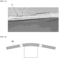
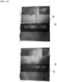
- Fig. 2 is a photograph that has been taken from a side surface of a conventional electrode assembly.
- Fig. 3 is a diagram that illustrates a test related to the stiffness of a conventional electrode assembly.
- the electrode assembly is a stacked type electrode assembly, and is formed by stacking unit cells in which a cathode 11, a separator 13, an anode 12 and a separator 13 are mainly stacked, or an anode 12, a cathode 11 and a separator 13 are sequentially stacked.
- the separator 13 is usually formed larger than the cathode 11 or the anode 12, the end of the separator 13 in the electrode assembly is present in a state of not being adhered to the cathode 11 or the anode 12, which may cause a problem that the end of the separator 13 is folded by an external force as in a region A of Fig. 2 .
- the overall stiffness of the electrode assembly may be deteriorated, such as being easily bent. In particular, this problem may occur more prominently on the long side of the separator 13 than on the short side.
- an electrode assembly is provided, preferably for a battery cell.
- electrodes in particular electrode sheets, and separators, in particular separator sheets, are alternately stacked in a stacking direction.
- the separators In at least one lengthwise and/or crosswise direction of the electrode assembly, the separators have a larger extension than the electrode.
- the separators have a larger extension into at least one of the lengthwise and/or crosswise direction in comparison to their immediately adjacent electrode (particularly in case of the lower- or topmost separator which may have only one adjacent electrode) or electrodes.
- the crosswise direction may generally refer to a direction crosswise, in particular perpendicular, with respect to the lengthwise direction.
- the stacking direction or stack height direction may preferably be defined crosswise, preferably perpendicular, with respect to the crosswise direction and crosswise, preferably perpendicular, with respect to the lengthwise direction.
- the multiple electrodes of the electrode assembly may optionally be of uniform size in the lengthwise and/or crosswise direction.
- the electrodes may include a first group of electrodes and a second group of electrodes, wherein the first group of electrodes is larger than the second group of electrodes in the lengthwise and/or crosswise direction, wherein the separators have a larger extension into at least one of the lengthwise and/or crosswise direction, preferably in the crosswise direction, in comparison to the first group of electrodes.
- the first group of electrodes and the second group of electrodes may comprise anodes and/or cathodes.
- the first group of electrodes may consist of anodes.
- the second group of electrodes may consist of cathodes.
- the separators preferably each, include at least one projection that protrudes beyond the electrode in the lengthwise and/or crosswise direction, preferably in the crosswise direction.
- the projections realize the larger extension of the separators.
- the separators in particular each, may comprise a first projection extending in the crosswise direction on a first side, for example on the left side, and/or a second projection extending in the crosswise direction on a second side, for example on the right side.
- the first side and the second side preferably face mutually opposite directions.
- a projection of a separator protruding in the crosswise direction preferably extends along the entire extension of the separator in the lengthwise direction.
- a projection of a separator protruding in the lengthwise direction preferably extends along the entire extension of the separator in the crosswise direction.
- the electrode assembly comprises at least one fixing member is arranged among a plurality of the separators.
- the at least one fixing member is attached to the projections of the separators adjacent to each other along the stacking direction.
- the fixing member is attached to all of them.
- the electrode member comprises a first fixing member attached to first projections extending on a first side of the electrode assembly, and a second fixing member attached to second projections extending on a second side of the electrode assembly.
- the fixing member may include or consist of a polymer material, in particular a duroplast material and/or a rubber material.
- the fixing member may in particular include or consist of PO, PUR, EVO, rubber, or a mixture, a blend, a copolymer thereof.
- the fixing member may comprise or consist of an adhesive member.
- a fixing member may be adapted to from a bond or connection with the separators, in particular an adhesion connection and/or a cohesion connection.
- the fixing member is configured to provide a structural reinforcement to the electrode assembly.
- the fixing member is configured realize a brace for the electrode assembly.
- the separator sheet may have generally the same shape but a larger size in the lengthwise and/or crosswise direction, wherein the size difference defines the projections.
- separator sheets may define a first area larger than a second area defined by the electrode sheets, wherein projections are defined by the area of the separator sheets protruding from the area of the adjacent electrode sheets.
- Electrodes comprise cathodes and anodes.
- the number of cathodes and anodes in the electrode assembly may be equal or differ, for example differ by one.
- the number of separators in the electrode assembly may be substantially equal to the number of electrodes or larger, for example larger by one or two.
- a separator may be arranged between two electrodes, an anode and a cathode, to keeps the adjacent electrodes apart so as to prevent electrical short circuits and/or to allow the transport of ionic charge carriers, such as an electrolyte solution between the adjacent electrodes.
- Electrode assemblies of the stacked (laminated) type and electrode assemblies of the stacked/folded type typically include electrode sheets and separator sheets.
- a stack may generally be understood to comprise of multiple separators and electrodes alternately layered (or: stacked) above one another.
- alternately stacked electrodes and separators in the electrode assembly are stacked, preferably directly above one another, in the order: separator - cathode - anode - separator - cathode - anode ... separator.
- sheet designates a generally planar structure, particularly having a lengthwise dimension and a crosswise direction, both of which are substantially, such as at least 10 times, in particular at least 20 times, more particularly at least 50 times or 100 times, larger than the height dimension of the sheet.
- a sheet may have equally or similarly large crosswise and lengthwise dimensions.
- the lengthwise direction of a sheet may be no less than 1/10, more particularly no less than 1/5, preferably no less than 1/3, and/or no more than 10 times, more particularly no more than 5 times, preferably no more than 3 times of the crosswise direction of the sheet.
- sheets, in particular separator sheets may be shaped, preferably by folding, into a zig-zag shape.
- sheet shall I the context of the present disclosure be understood to relate to a respective layer of composite sheet having multiple sheet-like layers (sheet sections) connected by bend sections or pillar sections extending in the stacking direction between successive sheet sections.
- a zigzag structure may extend over essentially the entire height of the electrode assembly in the stack height direction.
- an electrode assembly in which an electrode and a separator sheet are alternately stacked, wherein in one direction of the electrode assembly, the separator has a longer structure than the electrode, whereby the separator includes an projection that protrudes beyond the end part of the electrode, and wherein among a plurality of separators included in the electrode assembly, an fixing member for fixing between the projections of the separators adjacent to each other along a stacking direction of the electrode and the separator is formed.
- a projection may alternatively be designated as an extension part.
- the fixing member has a web structure comprising at least one line.
- a web structure may be realized completely or at least partially as a mesh structure, net structure, tangle structure, fleece structure and/or pattern structure.
- the web structure preferably comprises several lines.
- the line or lines each consist of a plurality of line sections.
- the at least one line may be continuously straight or curved.
- the at least one line may include straight line sections and/or curved line sections.
- the fixing member may in particular have a web structure comprising a plurality of lines.
- the plurality of lines may have substantially the same shape or different shapes.
- the line or lines may preferably be pigtail-shaped.
- the web structure comprises at least one of intersection formed by line sections.
- the web structure preferably comprises a plurality of intersection formed by line sections. An intersection generally designates a place where two or more lines overlap or coincide.
- the fixing member may have a pattern shape in which at least two lines intersect.
- the lines of the web structure have a line width.
- the line width may be at least 10 ⁇ m, in particular at least 20 ⁇ m.
- the line width may be no more than 200 ⁇ m, in particular no more than 100 ⁇ m.
- a preferred line width may be approximately 50 ⁇ m.
- the line width may designate a mean line width of a line section, more preferably of a line.
- the web structure may have distance between mutually adjacent lines of the web structure is at least 100 ⁇ m and/or no more than 800 ⁇ m.
- the web structure has a line width of 20 to 100 ⁇ m.
- the distance between mutually adjacent lines maybe understood to define the largest distance between those lines.
- the distance between mutually adjacent lines of the web structure may be 100 to 800 ⁇ m.
- the fixing member includes a plurality of openings.
- the fixing member may include at least 10, in particular at least 100, preferably at least 1000, openings per cm 2 electrode assembly surface area covered by the fixing member.
- the openings are configured to allow for electrolyte solution to flow through the fixing member.
- the openings are preferably relatively small.
- the openings may be smaller than 5 times the thickness of the fixing member, in particular smaller than 2 times the thickness of the fixing member, preferably smaller than the thickness of the fixing member.
- the openings define a clearance.
- the clearance may be defined by a distance between mutually adjacent lines.
- the openings may have a minimum clearance of no less than 10 ⁇ m.
- the clearance maybe no more than 1000 ⁇ m, in particular no more than 800 ⁇ m, preferably no more than 400 ⁇ m.
- the fixing member may include a web structure having a plurality of openings.
- the electrode assembly has a first, in particular lengthwise, dimension larger than a second, in particular crosswise, dimension, and a side surface defined in the stack height direction and the first direction.
- the side surface may be a right side surface or a left side surface.
- a left side surface may be provided with a first fixing member and a right side surface may be provided with a second fixing member.
- the fixing member covers the side surface at least partially, preferably completely, in the stack height direction.
- the fixing member covers the side surface at least partially, preferably completely, in the first direction. It may be preferred, that the fixing member covers the side surface completely in the stack height direction and at least partially in the first direction.
- the electrode assembly has a cuboid shape.
- the top and/or bottom surface of a cuboid shape electrode assembly is preferably defined by a separator, in particular a separator sheet.
- the front surface and/or back surface of the cuboid shape electrode assembly may be at least sectionally or completely free of a fixing member.
- the right and/or left side surface of the cuboid shape electrode assembly may be provided with at least one respective fixing member.
- the first direction may alternatively be called a "whole length direction".
- the fixing member may be formed by partially applying an adhesive along the whole length direction of the electrode assembly.
- the electrode assembly includes at least two electrode tabs protruding from the electrodes in the first direction.
- the at least two electrode tabs preferably include at least one cathode tab and at least one anode tab.
- the at least two electrode tabs may include a plurality of cathode tabs and/or anode tabs.
- the at least two electrode tabs may protrude in the same direction, forward or backward, from the electrodes.
- the at least two electrode tabs may protrude from the electrodes in different, preferably opposite directions.
- the protruding electrode tabs may be arranged on a front and/or back surface of the electrode assembly completely covered by a fixing member, sectionally covered by a fixing member or free of a fixing member.
- the electrode assembly further includes an electrode tab protruding from one end part of the electrode, wherein the whole length direction may be the same as a direction in which the electrode tab protrudes.
- the separator has a zigzag shape.
- the zigzag shape may include two or more sheets (sheet sections) and wall sections connecting adjacent sheets.
- the separator may have a zigzag shape formed by bending a rectangular sheet.
- the fixing member has an inside facing towards the electrodes and an outside facing away from the electrodes.
- the electrode assembly further comprises a finishing separator located on the outside of the fixing member, wherein preferably the finishing separator is attached to the outside of the fixing member.
- a finishing separator may be a separator beginning at a topmost or lowermost separator of the electrode assembly and enveloping at least one side surface, preferably two mutually opposite side surfaces, at least once.
- the finishing separator may wrap around the electrode structure, particularly in a spiral-like manner as seen in the first direction of the electrode assembly.
- the finishing separator may cover the top-, bottom-, left side and right side surface of the electrode assembly completely or at least partially.
- the finishing separator and may wrap the side surface of the cell stack on which the fixing member is formed. At this time, the finishing separator may be finished after surrounding one circle around the cell stack as a whole, and thus wrapping the side surface of the cell stack once.
- the finishing separators and the fixing member may be firmly attached to each other, Thereby, the overall stiffness of the electrode assembly can be further improved.
- a finishing separator may be located on the outside of the fixing member.
- the separators in particular the separator sheets, have mutually opposite first, in particular lengthwise, edges and mutually opposite second, in particular crosswise, edges, wherein the first edges are longer than the second edges.
- At least one edge, in particular first edge may be formed by the projection. Alternatively or additionally, at least one edge may be formed by a bent section or pillar section of a zigzag shaped composite separator.
- the fixing member is attached to separators adjacent to each other along the stacking direction along at least one of their respective first edges.
- the separator has long sides facing each other and short sides facing each other, and the fixing member may be formed on the long side of the separator.
- the fixing member covers at least 25 %, in particular at least 50 %, preferably at least 70 % if one, in particular first and/or second, side surface.
- the fixing member may cover a whole, in particular first and/or second, side surface of the electrode assembly.
- the fixing member no more than 90%, preferably no more than 80%, of one, in particular first and/or second, side surface of the electrode assembly.
- the fixing member may be formed so as to cover 70 to 80% of one side surface of the electrode assembly.
- the fixing member covering the side surface entirely or in part may be provided with a multitude of openings having a clearance as described above.
- the electrode assembly may be provided with a singular or one-piece fixing member covering one respective electrode assembly side surface.
- a surface area in particular a side surface area, which is covered by the fixing member essentially completely, at least 50%, preferably at least 66% or at least 75%, and/or no more than 95%, preferably no more than 80% or 75%, of the covered area is free of openings.
- the electrode assembly includes electrodes comprising at least one cathode and at least one anode
- the at least one cathode is distanced from the fixing member.
- the at least one anode is distanced from the fixing member.
- all of the electrodes are distanced from the fixing member.
- the distance between an electrode and the fixing member may be designated as a space or gap. Such a gap is defined between the edge of a respective electrode, the separator projections adjacent thereto, and the fixing member attached to those projections. Gaps configured to be filled with an electrolyte solution may be provided for separating the electrodes from the fixing member or members of the electrode assembly in the crosswise and/or lengthwise direction.
- the cathodes and/or anodes are distanced on either side from fixing members attached on opposite side surfaces of the electrode assembly.
- the electrode includes a cathode and an anode, and the end of the cathode may not come into contact with the fixing member.
- the fixing member has a thickness of at least 50 ⁇ m, in particular at least 100 ⁇ m or 200 ⁇ m, and/or no more than 1000 ⁇ m, in particular no more than 800 ⁇ m, preferably no more than 600 ⁇ m.
- the thickness of the fixing member relates to its extension perpendicular to the surface area it is attached to.
- the thickness of the fixing member covering surface extending in the first direction and in the stacking direction may be defined in the second direction.
- the fixing member may have a thickness of 100 to 600 ⁇ m.
- the fixing member covers the projections of the separators.
- the fixing member may for example be attached to the edges of the separators and the thickness of the fixing member extend outward from the edges.
- the fixing member is attached to the projections so as to protrude both inwardly and outwardly from the surface defined by the separator edges.
- the electrode assembly may comprise a battery case surrounding the electrode assembly, wherein a space is defined between the electrode assembly and the battery case, particularly in the second direction, wherein the thickness of the fixing member extends from the separators through said space, in particularly filling said space, such that the fixing member contacts the battery case.
- the fixing member is flush with the projections, in particular the edges, of the separators.
- the fixing member is contained within the electrode assembly between the separators, particularly does not protrude outward of the separators.
- the fixing member may comprise or consist of an adhesive member.
- the adhesive member may include a curable adhesive.
- the adhesive member may include a two-component or more-component adhesive.
- the adhesive member may be configured for of natural curing, moisture curing, UV curing, and the like.
- the adhesive member may preferably be realized as heat sealing member or adhesive tape member.
- the adhesive member be made of at least one component that is not readily dissolved in the electrolytic solution of the battery cell.
- a battery cell comprising the above-mentioned electrode assembly.
- the battery cell including the electrode assembly may be of stacked (laminated) type structure.
- the battery cell includes an electrode assembly as described above, wherein the electrode assembly is realized as a stacked/folded type electrode.
- the electrode assembly of the present disclosure and a battery cell including the same include fixing members applied to both ends of the electrode assembly, thereby capable of improving the separator folding phenomenon, and enhancing the overall stiffness.
- planar when referred to as “planar”, it means when a target portion is viewed from the upper side, and when referred to as “cross-sectional”, it means when a target portion is viewed from the side of a cross section cut vertically.
- Figs. 4 and 5 are diagrams showing an electrode assembly according to an embodiment of the present disclosure.
- the electrode assembly 100 of the present embodiment is a power generation element capable of charging and discharging, which may include electrodes 110 and 120 and a separator 130.
- the electrodes 110 and 120 included in the electrode assembly 100 may include a cathode 110 and an anode 120, and the separator 130 is interposed between the electrodes 110 and 120, so that the electrode assembly 100 can have a structure in which cathode 110 / separator 130 / anode 120 are alternately stacked.
- the positions of the cathode 110 and the anode 120 shown in Figs. 4 and 5 are shown for convenience, and the positions can be changed from each other.
- the electrode assembly 100 of the present embodiment includes the fixing member 140 formed on at least one (right or left) side surface or both (right and left) side surfaces.
- the electrode assembly 100 may include a fixing member 140 formed on a side surface of a cell stack in which the electrodes 110 and 120 and the separator 130 are alternately stacked.
- the cell stack refers to a stacked body of the electrodes 110 and 120 and the separator 130 in the electrode assembly 100 of the present embodiment, and may not include the fixing member 140.
- the side surface of the cell stack refers to the surface where the ends of the plurality of electrodes 110 and 120 and/or the separator 130 are exposed in the cell stack in which the electrodes 110 and 120 and the separator 130 are alternately stacked.
- the side surface of the cell stack may refer to one surface of the cell stack that extends long along the first, lengthwise direction (or: whole length direction) of the electrode assembly 100 (the Z-axis or lengthwise direction of Fig. 4 ) which is larger than the second, crosswise direction thereof.
- the size, in particular in the lengthwise direction and/or in the crosswise direction, of the separator 130 may be greater than the size of the electrodes 110 and 120.
- the lengthwise and/or crosswise, preferably the lengthwise, ends of the separator 130 may protrude beyond the ends of the electrodes 110 and 120. Specifically, in one direction (X-axis or crosswise direction in Fig.
- the separator 130 has a longer structure than the electrodes 100 and 120, so that the separator 130 includes a projection 138 protruding beyond the ends of the electrodes 110 and 120 on one, left or right, side thereof, or two mutually opposite projections 138.
- the pillar section (which subsequently shall be referred to by way of example as a "bent part") of the separator 130 may protrude beyond the ends of the electrodes 110 and 120.
- the end of the protruding separator 130 or the bent part of the composite zigzag-shaped separator 130 may be referred to as a 'projection 138'.
- the fixing member 140 may be formed by applying an adhesive.
- the adhesive may include a component that is not readily dissolved in the electrolytic solution.
- An example of the adhesive used for the fixing member 140 may include PO, PUR, EVA, and/or rubber series. Further, another example may be a curable adhesive capable of natural curing, moisture curing, UV curing, and the like.
- the fixing member 140 comes into contact with an projection 138 of the separator 130 that does not come into contact with the electrodes 110 and 120, so as to fix or rigidify the shape of the separator 130.
- the separator 130 and at least one other separator 130 adjacent thereto may be connected to each other by the fixing member 140. Multiple or even all separators 130 of the electrode assembly 100 can be connected using at least one fixing member 140.
- the fixing member 140 may come into contact with the separator 130. At this time, the fixing member 140 may be formed between the separators 130 as shown in Fig. 4 , and thus can formed so as to correspond to the projection 138 of the separator 130 and the position thereof.
- the fixing member 140 does not come into contact with the cathode 110. It has been found that in some embodiments, the fixing member 140 may disturb the flow of ions moving from the cathode 110 to the anode 120. Further, it may be preferred that the fixing member 140 does not come into contact with the anode 120. But as the anode 120 is not a direct charging region, and thus, the influence thereof may be less than the contact between the cathode 110 and the fixing member 140.
- the fixing member 140 may be formed on all side surfaces of the electrode assembly 100, but may be preferably formed on only a part of the side surfaces. It has been found that in some embodiments, when the fixing member 140 is formed on the whole of the side surface of the electrode assembly 100, the fixing member 140 impedes the gas discharge of the electrode assembly 100 in the electrolytic solution impregnation or activation process of the electrodes 110 and 120.
- surfaces facing in the lengthwise direction may be designated as a front surface or back surface.
- Surfaces facing in the crosswise direction may be designated as a left side surface or right side surface.
- the fixing member 140 may be formed so as to cover the whole of one side surface of the electrode assembly 100, or may be formed so as to cover 70 to 80% of the side surface, particularly while covering the entire height of this side surface in the stacking direction.
- the side surface of the electrode assembly 100 may have a 'height' formed through stacking.
- the side surface may have a first 'width' corresponding to the length of the long side (first side) or a second 'width' corresponding to the short side (second side) in the electrode assembly 100.
- the fixing member 140 may be formed so as to cover 70 to 80% of the width, preferably the first width, of the side surface, preferably the first side surface, of the electrode assembly 100.
- the fixing member 140 may be configured so as not to cover the whole of the side surfaces of the electrode assembly 100, thereby capable of preventing the gas discharge of the electrode assembly 100 from being impeded by the fixing member 140 in the electrolytic solution impregnation or activation process of the electrodes 110 and 120.
- the fixing member 140 may be formed on a surface where the long side of the separator 130 is located among the side surfaces of the electrode assembly 100.
- the fixing member 140 may be formed on the long side of the separator 130. It has been found that in some embodiments, the folding phenomenon or the like occurs more frequently on the long side of the separator 130 having a relatively longer length than on the short side. However, such an explanation does not completely exclude that the fixing member 140 can be formed on the short side of the separator 130.
- the fixing member 140 may be joined together across multiple levels in the stacking direction by including portions 142 thereof that extend around the lateralmost outer edges of the separator 130.
- Fig. 6 is a photograph that has been taken from a side surface of the electrode assembly.
- Fig. 7 is a diagram that illustrates a test related to the stiffness of the electrode assembly.
- the fixing member 140 can serve to prevent a phenomenon in which the end of the separator 130 is folded and supplement the stiffness of the electrode assembly 100.
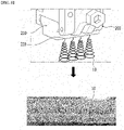
- Fig. 8 is a view showing an example of a device for applying an adhesive to the electrode assembly and the applied adhesive.
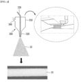
- Fig. 9 is a view illustrating an apparatus for applying an adhesive to an electrode assembly and another example of the applied adhesive.
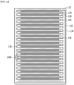
- the fixing member 140 of the present embodiment may be formed as a network of strands 144 of the adhesive material.
- the network of strands may have a form similar to a web structure.
- the network of strands 144 include multiple nodes or crossing locations 146 where a strand 144 of adhesive material intersects or crosses over another strand 144 of material.
- the web structure is realized by a patterning method.
- a patterning method may be realized using one or more, for example four, printing units being operated while over the side surface to be provided with the fixing member according to a random or predetermined pattern.
- the patterning method may mean applying an adhesive so that the adhesive 10 applied to the target position has a predetermined pattern. While the illustrated pattern is a pigtail pattern, other patterns may likewise be applied.
- the adhesive application device 200 based on the patterning method may include a housing 210 and a nozzle 220.
- the adhesive 10 may be supplied from the outside of the device 200 and housed in the housing 210, and the adhesive 10 that has passed through the nozzle 220 can be discharged in the form of a line.
- the applied adhesive 10 may have a specific pattern according to the movement of the nozzle 220. As an example, the adhesive 10 is spirally applied to the bottom of Fig. 8 and thus, it is shown that a large number of circular shapes have an overlapping web structure. Such a web structure may be referred to as a pig tail shape or a pig tail pattern.
- the fixing member 140 may be formed by a surface application method.
- the surface application method may mean applying an adhesive with a high density so that the adhesive 10 is applied to the target position without gaps.
- the adhesive application device 300 based on the surface application method can apply the adhesive 10 so that the adhesive 10 covers the whole of the target portion as shown in the below photograph of Fig. 9 .
- the adhesive application device 300 by the surface coating method can apply the adhesive through a spray, slot, or other method.
- the adhesive application device 300 based on the surface application method may include a housing 310, a nozzle 320, and a tube 330 through which the adhesive 10 is supplied into the housing 310, and an air tube 340 for injecting a compressed air when the adhesive 10 is sprayed through the nozzle 320 connected to the tube 330.
- the adhesive application device 300 based on the surface application method of Fig. 9 uses a compressed air, or the like, there is a fear that a scattering phenomenon of the adhesive 10 may occur at the time of spraying the adhesive 10. Further, when the thickness of the fixing member 140 is to be formed thick, there is a disadvantage in that the uniformity of the fixing member 140 is deteriorated.
- the adhesive application device 200 of Fig. 8 discharges the adhesive 10 in the form of a line, the scattering phenomenon of the adhesive by air or the like can be minimized, and the contamination of the device can be minimized. Further, the device 200 of Fig. 8 adjusts the distance between the lines so that the density and thickness of the fixing member 140 can be relatively freely adjusted. The device 200 of Fig. 8 applies the adhesive 10 in a certain pattern, so that the adhesive 10 can be applied more uniformly than the adhesive application device 300 of Fig. 9 even when the thickness of the fixing member 140 is to be formed thick.
- the device 200 of Fig. 8 can minimize the thickness of the fixing member 140 as compared with the device 300 of Fig. 9 .
- the thickness of the fixing member 140 formed through the device 200 of Fig. 8 is about 100 ⁇ m or more, whereas the thickness of the fixing member 140 formed through the device 300 of Fig. 9 may be about 200 ⁇ m or more.
- the device 200 of Fig. 8 applies the adhesive 10 in the form of a line as described above.
- the thickness of the fixing member 140 formed on the electrode assembly 100 can be variously set according to a design. For example, considering the size of the space between the electrode assembly 100 and the battery case in the battery cell, the thickness of the fixing member 140 can be designed to be less than or equal to that size. As a specific example, when the electrode assembly 100 is incorporated in the battery case in a state where the fixing member 140 is not formed, the separation distance between the electrode assembly 100 and the battery case may be about 600 ⁇ m. In this case, the thickness of the fixing member 140 formed on the electrode assembly 100 maybe 600 ⁇ m or less, 500 ⁇ m or less, 400 ⁇ m or less, 300 ⁇ m or less, or 200 ⁇ m or less.
- the thickness of the fixing member 140 formed on the electrode assembly 100 may be 100 to 600 ⁇ m, 100 to 500 ⁇ m, 100 to 400 ⁇ m, 100 to 300 ⁇ m, or 100 to 200 ⁇ m.
- the fixing member 140 may be formed by repeatedly stacking lines by the device 200 of Fig. 8 .
- the adhesive 10 provided through the adhesive application device may have a predetermined temperature.
- the adhesive application device adjusts the temperature of the adhesive 10 so that the adhesive 10 is easily applied.
- the operating temperature of the device 200 of Fig. 8 is 110°C, and the temperature of the adhesive 10 discharged from the device 200 maybe in the range of 40°C to 50°C.
- the operating temperature of the device 300 of Fig. 9 is 160°C, and the temperature of the adhesive 10 discharged from the device 200 may be the level of 60°C to 70°C. If the temperature of the adhesive 10 is high, the separator 130 is highly likely to contract.
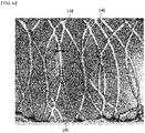
- Fig. 10 is a photograph comparing the adhesives applied using the devices of Figs. 8 and 9 .
- Fig. 11 is an enlarged photograph of a region B of Fig. 10 .
- the application shape of the adhesive according to the devices of Figs. 8 and 9 can be compared.
- the corresponding shape may be the shape of the fixing member 140 applied to the side surface of the electrode assembly 100.
- Fig. 10(a) is based on a patterning method, and may be formed by the device 200 of Fig. 8 .
- the adhesive 10 discharged in a linear shape is repeated.
- the linear shape is repeated in a spiral shape or a circular shape to form a pattern.
- the fixing member 140 formed by the patterning method may have a pattern in which at least two lines intersect.
- a structure, particularly a planar structure, formed by one or more lines consisting of line sections, some of which intersect can generally be designated as a web structure.
- the fixing member 140 formed by the patterning method may include a plurality of openings.
- the line width of the adhesive 10 by the patterning method may be 20 to 100 ⁇ m, and the distance between the lines may be 100 to 800 ⁇ m.
- the fixing member 140 has a pig tail pattern.
- the first line width d1 is 50 ⁇ m, and the first line distance w1 is 600 ⁇ m.
- Fig. 10(b) is based on a surface application method, and may be formed by the device 300 of Fig. 9 .
- the gap between the adhesives 10 may not be present and it is applied so as to form one singular surface.
- openings are not formed in the fixing member 140.
- the fixing member 140 of the present embodiment is formed on the side surface of the electrode assembly 100, the fixing member 140 can prevent the electrolytic solution absorbed through the side surface of the electrode assembly 100 from coming into contact with the electrodes 110 and 120.
- the fixing member 140 may be formed to minimize any decrease in absorption of the electrolytic solution.
- Fig. 12 is a photograph of a test related to the wettability of the electrode assembly to which the processes of Figs. 8 and 9 are applied. Specifically, Fig. 12 is obtained by impregnating the electrode assembly 100 having the fixing member 140, formed through the processes of Figs. 8 and 9 , with the electrolytic solution, followed by disassembling. A section in which the electrolytic solution is not absorbed in the electrodes 110 and 120 as shown in the photograph can be designated as a non-wetting region 20, and based on this the wettability of the electrodes 110 and 120 with respect to the electrolytic solution and any reduction thereof through the fixing member 140 may be assumed.
- the non-wetting region 20 is smaller, it may mean that the contact between the electrodes 110 and 120 and the electrolytic solution are sufficient.
- the electrodes 110 and 120 of Fig. 12(a) to which the patterning method of Fig. 8 is applied have a smaller non-wetting region 20 than the electrodes 110 and 120 of Fig. 12 (b) to which the surface application method of Fig. 9 is applied.
- the fixing member 140 formed by Fig. 8 may not interfere with the absorption of the electrolytic solution than the fixing member 140 formed by Fig. 9 .
- the pattern application method of Fig. 8 has a pattern in which a plurality of lines intersect, it may be formed so as to include a plurality of openings in the fixing member 140.
- the electrolytic solution can be absorbed into the inside of the electrode assembly 100 through the opening, whereby the fixing member 140 by the pattern application method can suppress a substantial decrease in penetration of the electrolytic solution. If the electrolytic solution is not well absorbed by the electrodes 110 and 120, the output characteristics of the electrode assembly 100 can be deteriorated. Therefore, even when the fixing member 140 is formed by the surface application method of Fig. 9 , the absorption rate of the electrolytic solution can be increased by partially forming the fixing member 140 on the side surface of the electrode assembly 100. However, in the case of partially forming the fixing member 140 in this way, since the stiffness of the electrode assembly 100 can be reduced as shown in Fig. 3 , the application position and application level of the fixing member 140 may have to be designed strictly.
- the electrode assembly of the present embodiment is the same as the above-mentioned electrode assembly except that the shape of the cell stack is different. Therefore, unless otherwise stated, the electrode assembly according to the present embodiment may be described as including all the contents related to the electrode assembly of Figs. 4 to 12 described above.
- Figs. 13 and 14 are diagrams showing an electrode assembly according to another embodiment of the present disclosure.
- the electrode assembly 100 of the present embodiment may include a cell stack in which a cathode 110 / a separator 130 / an anode 120 are alternately stacked and finishing separators 132 and 134 surrounding the side surface of the cell stack.
- the separator 130 has a zigzag shape formed by bending a rectangular separator sheet, and the separator 130 bent in a zigzag may be interposed between the cathode 110 and the anode 120.
- the separator 130 can wrap the side surface of the cell stack at least once via the finishing separators 132 and 134, so that the side surface of the cell stack can be finished.
- the positions of the cathode 110 and the anode 120 shown in Figs. 13 and 14 are shown for convenience, and the positions can be changed from each other.
- the fixing member 140 can be formed on a side surface of the cell stack.
- the fixing member 140 comes into contact with the projection 138 of the separator 130 and connects the projection 138, so that the shape of the separator 130 can be fixed.
- the fixing member 140 connects the bent part 138B of the separator 130, that is, the bent part 138B of the separator 130, so that the overall shape of the separator 130 can be fixed.
- the overall shape of the cell stack including the separator 130 is fixed by the fixing member 140, and can ensure minimum stiffness.
- the fixing member 140 may be formed on all side surfaces of the cell stack as described above, but can be formed on both side surfaces where the bent separation film 130 is located as shown in Figs. 13 and 14 . Further(not shown in Figs. 13 and 14 ), it can be formed on the other side (particularly the front side or back side) of the cell stack. However, in the process of impregnating or activating the electrodes 110 and 120 with an electrolytic solution, since the discharge of gas from the electrode assembly 100 can be disturbed by the fixing member 140, the position of the fixing member 140 needs to be properly designed, and it may not be desirable to be formed so as to cover all side surfaces of the cell stack. Further, the fixing member 140 may be formed so as to cover the whole of one side surface of the electrode assembly 100, or may be formed so as to cover 70 to 80% of the side surface of the electrode assembly 100.
- finishing separators 132 and 134 may be formed on the outside of the fixing member 140.
- the finishing separators 132 and 134 may wrap the side surface of the cell stack on which the fixing member 140 is formed.
- the finishing separator 132 may be finished after surrounding one circle around the cell stack as a whole, and thus wrapping the side surface of the cell stack once.
- the finishing separators 132 and 134 are finished after surrounding two circles or more around the cell stack as a whole, and thus wrapping the side surface of the cell stack twice or more as shown in Fig. 14 .
- the side surface of the cell stack can be finished by attaching an adhesive means such as heat sealing or adhesive tape, and the finishing method may be implemented by changing in various ways in addition to the above-mentioned embodiments.
- the manufacturing method (S1000) of the electrode assembly of the present embodiment may include a step of forming a cell stack in which the electrodes 110 and 120 and the separator 130 are alternately stacked (S1100), a step of applying the adhesive 10 to the side surface of the cell stack (S1200) and a step of forming the fixing member 140 for fixing the separator 130 (S1300).
- the step of forming the cell stack (S1100), any known method can be used as long as the electrode and the separator are stacked in the order of the cathode 110, the separator 130, the anode 120 and the separator 130 or in the order of the anode 120 , the separator 130, the cathode 110 and the separator 130.
- the cell stack can be manufactured in a stacked type as shown in Figs. 4 and 5 , or may be manufactured in a zig-zag shape as shown in Figs. 13 and 14 .
- the device 200 of Fig. 8 can be used, or the application device 300 of Fig. 9 can be used.
- the step (S1200) may include a step of determining the application pattern of the adhesive 10, and/or a step of moving the nozzle 220 to the determined pattern to apply the adhesive in a pattern.
- the step of determining the application pattern of the adhesive 10 may be performed before the step of forming the cell stack (S1100).
- the step of forming the fixing member 140 may include a step of drying the adhesive 10. Further, depending on the nature of the adhesive 10, the adhesive 10 can be solidified by heat curing or UV curing, and in such a case, the step of forming the fixing member 140 (S1300) may include a step of curing the adhesive 10.
- the above-mentioned method may further include a step of finishing the side surface of the cell stack (S1400).
- the finishing separators 132 and 134 may be formed on the side surface of the cell stack.
- the finishing separators 132 and 134 may be finished after wrapping the side surface of the cell stack at least once.
- the finishing separators 132 and 134 may wrap the side surface of the cell stack once as shown in Fig. 13 , and the side surface of the cell stack may be wrapped twice or more as shown inf Fig. 14 .
- the method of manufacturing the electrode assembly 100 according to the present embodiment may further include a step of pressing along one direction (X-axis direction) toward the side surface of the cell stack, after the formation of the finishing separators 132 and 134.
- finishing separators 132 and 134 and the fixing member 140 are adhered to each other, so that the overall stiffness of the electrode assembly can be further improved.
- the finishing separators 132 and 134 have an effect of more strongly winding the electrode assembly. Accordingly, it is possible to prevent the battery cell from being bent.
- the electrode assembly 100 of the present embodiment described above is housed in a cell case together with an electrolytic solution and can be provided as a battery cell.
- a battery cell may include an electrode assembly 100 in which a plurality of electrodes and a plurality of separators are alternately stacked, electrode leads connected to electrode tabs extending from a plurality of electrodes, and a cell case for sealing the electrode assembly in a state where one end of the electrode lead protrude.
- the above-mentioned battery cell can be stacked in one direction to form a battery cell stack, and a battery pack can be formed together with a battery management system (BMS) and/or a cooling device that is modularized into a battery module and manages the temperature or voltage of the battery.
- BMS battery management system
- the battery pack can be applied to various devices.
- the device to which the battery pack is applied may be a vehicle means such as an electric bicycle, an electric vehicle, or a hybrid vehicle, but the present disclosure is not limited thereto, and the battery pack according to the present embodiment can be used for various devices in addition to the above illustrations, which also falls within the scope of the present disclosure.
Landscapes
- Chemical & Material Sciences (AREA)
- Chemical Kinetics & Catalysis (AREA)
- Electrochemistry (AREA)
- General Chemical & Material Sciences (AREA)
- Engineering & Computer Science (AREA)
- Manufacturing & Machinery (AREA)
- Secondary Cells (AREA)
- Cell Separators (AREA)
- Connection Of Batteries Or Terminals (AREA)
Abstract
Description
- The present disclosure relates to an electrode assembly and a battery cell including the same, and more particularly, an electrode assembly that prevents the folding phenomenon of the separator, and a battery cell including the same.
- In modern society, as portable devices such as mobile phones, notebook computers, camcorders and digital cameras are used daily, the development of technologies in the fields related to such mobile devices has been substantial. In addition, chargeable/dischargeable secondary batteries are used as a power source for an electric vehicle (EV), a hybrid electric vehicle (HEV), a plug-in hybrid electric vehicle (P-HEV) and the like, in an attempt to solve air pollution and the like caused by existing gasoline vehicles using fossil fuel. Therefore, there is a growing need for improvements of secondary batteries.
- Currently commercialized secondary batteries include nickel cadmium batteries, nickel hydrogen batteries, nickel zinc batteries, and lithium secondary batteries. Of these, the lithium secondary battery has come into the spotlight because of its advantages, for example, hardly exhibiting memory effects compared to nickel-based secondary batteries and so that it may be freely charged and discharged, and for having very low self-discharge rate and high energy density.
- Secondary batteries may be according to the shape of a battery case into a cylindrical battery having an electrode assembly mounted in a cylindrical metal can, a prismatic battery having an electrode assembly mounted in a prismatic metal can, and a pouch type battery having an electrode assembly mounted in a pouch-shaped case made of a laminated aluminum sheet.
- Further, secondary batteries may be classified according to the structure of an electrode assembly having a structure in which a cathode and an anode are stacked with a separator being interposed between the cathode and the anode. Typically, they may be designated as a jelly-roll (wound) type structure in which a long sheet type cathode and a long sheet type anode are wound with a separator being interposed between the cathode and the anode, as a stacked (laminated) type structure in which pluralities of cathodes and anodes, cut into predetermined unit sizes, are sequentially stacked with separators being interposed between the cathodes and the anodes, or the like. In recent years, in order to solve problems caused by the jelly-roll type electrode assembly and the stacked type electrode assembly, there has been developed a stacked/folded type electrode assembly, which is a combination of the jelly-roll type electrode assembly and the stacked type electrode assembly.
-
Fig. 1 is a side view of a conventional electrode assembly.Fig. 2 is a photograph that has been taken from a side surface of a conventional electrode assembly.Fig. 3 is a diagram that illustrates a test related to the stiffness of a conventional electrode assembly. - Referring to
Fig. 1 , the electrode assembly is a stacked type electrode assembly, and is formed by stacking unit cells in which acathode 11, aseparator 13, ananode 12 and aseparator 13 are mainly stacked, or ananode 12, acathode 11 and aseparator 13 are sequentially stacked. - Meanwhile, since the
separator 13 is usually formed larger than thecathode 11 or theanode 12, the end of theseparator 13 in the electrode assembly is present in a state of not being adhered to thecathode 11 or theanode 12, which may cause a problem that the end of theseparator 13 is folded by an external force as in a region A ofFig. 2 . Further, as shown inFig. 3 , when an uneven force is applied to the electrode assembly, the overall stiffness of the electrode assembly may be deteriorated, such as being easily bent. In particular, this problem may occur more prominently on the long side of theseparator 13 than on the short side. - It is an object of the present disclosure to provide an electrode assembly that improves a separator folding phenomenon of the electrode assembly and enhances the overall stiffness, and a battery cell including the same.
- However, the problem to be solved by the embodiments of the present disclosure is not limited to the above-described problems, and can be variously expanded within the scope of the technical idea included in the present disclosure.
- According to one embodiment of the present disclosure, an electrode assembly is provided, preferably for a battery cell. In the electrode assembly, electrodes, in particular electrode sheets, and separators, in particular separator sheets, are alternately stacked in a stacking direction. In at least one lengthwise and/or crosswise direction of the electrode assembly, the separators have a larger extension than the electrode. In particular, the separators have a larger extension into at least one of the lengthwise and/or crosswise direction in comparison to their immediately adjacent electrode (particularly in case of the lower- or topmost separator which may have only one adjacent electrode) or electrodes.
- The crosswise direction may generally refer to a direction crosswise, in particular perpendicular, with respect to the lengthwise direction. The stacking direction or stack height direction may preferably be defined crosswise, preferably perpendicular, with respect to the crosswise direction and crosswise, preferably perpendicular, with respect to the lengthwise direction.
- The multiple electrodes of the electrode assembly may optionally be of uniform size in the lengthwise and/or crosswise direction. In some embodiments, the electrodes may include a first group of electrodes and a second group of electrodes, wherein the first group of electrodes is larger than the second group of electrodes in the lengthwise and/or crosswise direction, wherein the separators have a larger extension into at least one of the lengthwise and/or crosswise direction, preferably in the crosswise direction, in comparison to the first group of electrodes. The first group of electrodes and the second group of electrodes may comprise anodes and/or cathodes. The first group of electrodes may consist of anodes. The second group of electrodes may consist of cathodes.
- The separators, preferably each, include at least one projection that protrudes beyond the electrode in the lengthwise and/or crosswise direction, preferably in the crosswise direction. Preferably, the projections realize the larger extension of the separators. The separators, in particular each, may comprise a first projection extending in the crosswise direction on a first side, for example on the left side, and/or a second projection extending in the crosswise direction on a second side, for example on the right side. The first side and the second side preferably face mutually opposite directions. A projection of a separator protruding in the crosswise direction preferably extends along the entire extension of the separator in the lengthwise direction. A projection of a separator protruding in the lengthwise direction preferably extends along the entire extension of the separator in the crosswise direction.
- The electrode assembly comprises at least one fixing member is arranged among a plurality of the separators. The at least one fixing member is attached to the projections of the separators adjacent to each other along the stacking direction. In particular, in an electrode assembly having at least one side on which projections of multiple separators protrude, the fixing member is attached to all of them. Preferably, the electrode member comprises a first fixing member attached to first projections extending on a first side of the electrode assembly, and a second fixing member attached to second projections extending on a second side of the electrode assembly. The fixing member may include or consist of a polymer material, in particular a duroplast material and/or a rubber material. The fixing member may in particular include or consist of PO, PUR, EVO, rubber, or a mixture, a blend, a copolymer thereof. The fixing member may comprise or consist of an adhesive member. A fixing member may be adapted to from a bond or connection with the separators, in particular an adhesion connection and/or a cohesion connection. Preferably, the fixing member is configured to provide a structural reinforcement to the electrode assembly. Alternatively or additionally, the fixing member is configured realize a brace for the electrode assembly. In a preferred embodiment in which electrodes and separators are realized as sheets, the separator sheet may have generally the same shape but a larger size in the lengthwise and/or crosswise direction, wherein the size difference defines the projections. In other words, separator sheets may define a first area larger than a second area defined by the electrode sheets, wherein projections are defined by the area of the separator sheets protruding from the area of the adjacent electrode sheets.
- Electrodes comprise cathodes and anodes. The number of cathodes and anodes in the electrode assembly may be equal or differ, for example differ by one. The number of separators in the electrode assembly may be substantially equal to the number of electrodes or larger, for example larger by one or two. A separator may be arranged between two electrodes, an anode and a cathode, to keeps the adjacent electrodes apart so as to prevent electrical short circuits and/or to allow the transport of ionic charge carriers, such as an electrolyte solution between the adjacent electrodes.
- Electrode assemblies of the stacked (laminated) type and electrode assemblies of the stacked/folded type typically include electrode sheets and separator sheets. A stack may generally be understood to comprise of multiple separators and electrodes alternately layered (or: stacked) above one another. Preferably, alternately stacked electrodes and separators in the electrode assembly are stacked, preferably directly above one another, in the order: separator - cathode - anode - separator - cathode - anode ... separator. The term sheet designates a generally planar structure, particularly having a lengthwise dimension and a crosswise direction, both of which are substantially, such as at least 10 times, in particular at least 20 times, more particularly at least 50 times or 100 times, larger than the height dimension of the sheet. A sheet may have equally or similarly large crosswise and lengthwise dimensions. In particular, the lengthwise direction of a sheet may be no less than 1/10, more particularly no less than 1/5, preferably no less than 1/3, and/or no more than 10 times, more particularly no more than 5 times, preferably no more than 3 times of the crosswise direction of the sheet. In a stacked/folded type electrode assembly, sheets, in particular separator sheets, may be shaped, preferably by folding, into a zig-zag shape. In this case, it shall be understood that the term "sheet" shall I the context of the present disclosure be understood to relate to a respective layer of composite sheet having multiple sheet-like layers (sheet sections) connected by bend sections or pillar sections extending in the stacking direction between successive sheet sections. A zigzag structure may extend over essentially the entire height of the electrode assembly in the stack height direction.
- In particular there may be provided an electrode assembly in which an electrode and a separator sheet are alternately stacked, wherein in one direction of the electrode assembly, the separator has a longer structure than the electrode, whereby the separator includes an projection that protrudes beyond the end part of the electrode, and wherein among a plurality of separators included in the electrode assembly, an fixing member for fixing between the projections of the separators adjacent to each other along a stacking direction of the electrode and the separator is formed. A projection may alternatively be designated as an extension part.
- According to one embodiment of an electrode assembly, the fixing member has a web structure comprising at least one line. A web structure may be realized completely or at least partially as a mesh structure, net structure, tangle structure, fleece structure and/or pattern structure. The web structure preferably comprises several lines. The line or lines each consist of a plurality of line sections. The at least one line may be continuously straight or curved. The at least one line may include straight line sections and/or curved line sections. The fixing member may in particular have a web structure comprising a plurality of lines. The plurality of lines may have substantially the same shape or different shapes. The line or lines may preferably be pigtail-shaped. The web structure comprises at least one of intersection formed by line sections. The web structure preferably comprises a plurality of intersection formed by line sections. An intersection generally designates a place where two or more lines overlap or coincide. In particular, the fixing member may have a pattern shape in which at least two lines intersect.
- In one embodiment of the electrode assembly, the lines of the web structure have a line width. The line width may be at least 10 µm, in particular at least 20 µm. The line width may be no more than 200 µm, in particular no more than 100 µm. A preferred line width may be approximately 50 µm. Preferably, the line width may designate a mean line width of a line section, more preferably of a line. Alternatively or additionally, the web structure may have distance between mutually adjacent lines of the web structure is at least 100 µm and/or no more than 800 µm. In particular, the web structure has a line width of 20 to 100 µm. Preferably, the distance between mutually adjacent lines maybe understood to define the largest distance between those lines. In particular, the distance between mutually adjacent lines of the web structure may be 100 to 800 µm.
- Additionally or alternatively, in one embodiment of the electrode assembly, the fixing member includes a plurality of openings. The fixing member may include at least 10, in particular at least 100, preferably at least 1000, openings per cm2 electrode assembly surface area covered by the fixing member. Preferably, the openings are configured to allow for electrolyte solution to flow through the fixing member. The openings are preferably relatively small. The openings may be smaller than 5 times the thickness of the fixing member, in particular smaller than 2 times the thickness of the fixing member, preferably smaller than the thickness of the fixing member. In particular the openings define a clearance. In a web structure, the clearance may be defined by a distance between mutually adjacent lines. Optionally, the openings may have a minimum clearance of no less than 10 µm. The clearance maybe no more than 1000 µm, in particular no more than 800 µm, preferably no more than 400 µm. In particular, the fixing member may include a web structure having a plurality of openings.
- In one embodiment, the electrode assembly has a first, in particular lengthwise, dimension larger than a second, in particular crosswise, dimension, and a side surface defined in the stack height direction and the first direction. The side surface may be a right side surface or a left side surface. Preferably, a left side surface may be provided with a first fixing member and a right side surface may be provided with a second fixing member. The fixing member covers the side surface at least partially, preferably completely, in the stack height direction. Alternatively or additionally, the fixing member covers the side surface at least partially, preferably completely, in the first direction. It may be preferred, that the fixing member covers the side surface completely in the stack height direction and at least partially in the first direction. Preferably, the electrode assembly has a cuboid shape. The top and/or bottom surface of a cuboid shape electrode assembly is preferably defined by a separator, in particular a separator sheet. The front surface and/or back surface of the cuboid shape electrode assembly may be at least sectionally or completely free of a fixing member. The right and/or left side surface of the cuboid shape electrode assembly may be provided with at least one respective fixing member. The first direction may alternatively be called a "whole length direction". In particular, the fixing member may be formed by partially applying an adhesive along the whole length direction of the electrode assembly.
- In a further development, the electrode assembly includes at least two electrode tabs protruding from the electrodes in the first direction. The at least two electrode tabs preferably include at least one cathode tab and at least one anode tab. The at least two electrode tabs may include a plurality of cathode tabs and/or anode tabs. The at least two electrode tabs may protrude in the same direction, forward or backward, from the electrodes. Alternatively, the at least two electrode tabs may protrude from the electrodes in different, preferably opposite directions. The protruding electrode tabs may be arranged on a front and/or back surface of the electrode assembly completely covered by a fixing member, sectionally covered by a fixing member or free of a fixing member. In particular, the electrode assembly further includes an electrode tab protruding from one end part of the electrode, wherein the whole length direction may be the same as a direction in which the electrode tab protrudes.
- According to a preferred embodiment, the separator has a zigzag shape. The zigzag shape may include two or more sheets (sheet sections) and wall sections connecting adjacent sheets. In particular, the separator may have a zigzag shape formed by bending a rectangular sheet.
- In one embodiment of a separator assembly, the fixing member has an inside facing towards the electrodes and an outside facing away from the electrodes. The electrode assembly further comprises a finishing separator located on the outside of the fixing member, wherein preferably the finishing separator is attached to the outside of the fixing member. A finishing separator may be a separator beginning at a topmost or lowermost separator of the electrode assembly and enveloping at least one side surface, preferably two mutually opposite side surfaces, at least once. The finishing separator may wrap around the electrode structure, particularly in a spiral-like manner as seen in the first direction of the electrode assembly. The finishing separator may cover the top-, bottom-, left side and right side surface of the electrode assembly completely or at least partially. The finishing separator and may wrap the side surface of the cell stack on which the fixing member is formed. At this time, the finishing separator may be finished after surrounding one circle around the cell stack as a whole, and thus wrapping the side surface of the cell stack once. The finishing separators and the fixing member may be firmly attached to each other, Thereby, the overall stiffness of the electrode assembly can be further improved. A finishing separator may be located on the outside of the fixing member.
- According to one embodiment of the electrode assembly, the separators, in particular the separator sheets, have mutually opposite first, in particular lengthwise, edges and mutually opposite second, in particular crosswise, edges, wherein the first edges are longer than the second edges. At least one edge, in particular first edge, may be formed by the projection. Alternatively or additionally, at least one edge may be formed by a bent section or pillar section of a zigzag shaped composite separator. The fixing member is attached to separators adjacent to each other along the stacking direction along at least one of their respective first edges.
- In particular, the separator has long sides facing each other and short sides facing each other, and the fixing member may be formed on the long side of the separator.
- In one particular embodiment of the electrode assembly, the fixing member covers at least 25 %, in particular at least 50 %, preferably at least 70 % if one, in particular first and/or second, side surface. The fixing member may cover a whole, in particular first and/or second, side surface of the electrode assembly. Alternatively or additionally, the fixing member no more than 90%, preferably no more than 80%, of one, in particular first and/or second, side surface of the electrode assembly. In particular, the fixing member may be formed so as to cover 70 to 80% of one side surface of the electrode assembly. The fixing member covering the side surface entirely or in part may be provided with a multitude of openings having a clearance as described above. The electrode assembly may be provided with a singular or one-piece fixing member covering one respective electrode assembly side surface. In particular, of a surface area, in particular a side surface area, which is covered by the fixing member essentially completely, at least 50%, preferably at least 66% or at least 75%, and/or no more than 95%, preferably no more than 80% or 75%, of the covered area is free of openings. Experiments have shown a good balance between permeability and stiffness.
- In one embodiment in which the electrode assembly includes electrodes comprising at least one cathode and at least one anode, the at least one cathode is distanced from the fixing member. Alternatively, the at least one anode is distanced from the fixing member. Optionally, all of the electrodes are distanced from the fixing member. The distance between an electrode and the fixing member may be designated as a space or gap. Such a gap is defined between the edge of a respective electrode, the separator projections adjacent thereto, and the fixing member attached to those projections. Gaps configured to be filled with an electrolyte solution may be provided for separating the electrodes from the fixing member or members of the electrode assembly in the crosswise and/or lengthwise direction. It may be preferred that the cathodes and/or anodes, preferably at least the cathodes, are distanced on either side from fixing members attached on opposite side surfaces of the electrode assembly. In particular, the electrode includes a cathode and an anode, and the end of the cathode may not come into contact with the fixing member.
- According to a further embodiment of the electrode assembly that can be combined with the abovementioned ones, the fixing member has a thickness of at least 50 µm, in particular at least 100 µm or 200 µm, and/or no more than 1000 µm, in particular no more than 800 µm, preferably no more than 600 µm. It should be clear that the thickness of the fixing member relates to its extension perpendicular to the surface area it is attached to. Preferably, the thickness of the fixing member covering surface extending in the first direction and in the stacking direction may be defined in the second direction. In particular, the fixing member may have a thickness of 100 to 600 µm.
- In one embodiment of the electrode assembly, that can be combined with the abovementioned ones, the fixing member covers the projections of the separators. The fixing member may for example be attached to the edges of the separators and the thickness of the fixing member extend outward from the edges. According to another example, the fixing member is attached to the projections so as to protrude both inwardly and outwardly from the surface defined by the separator edges. Preferably, the electrode assembly may comprise a battery case surrounding the electrode assembly, wherein a space is defined between the electrode assembly and the battery case, particularly in the second direction, wherein the thickness of the fixing member extends from the separators through said space, in particularly filling said space, such that the fixing member contacts the battery case.
- According to an alternative embodiment, the fixing member is flush with the projections, in particular the edges, of the separators. In this embodiment, the fixing member is contained within the electrode assembly between the separators, particularly does not protrude outward of the separators.
- The fixing member may comprise or consist of an adhesive member. The adhesive member may include a curable adhesive. The adhesive member may include a two-component or more-component adhesive. In particular, the adhesive member may be configured for of natural curing, moisture curing, UV curing, and the like. The adhesive member may preferably be realized as heat sealing member or adhesive tape member. Preferably, the adhesive member be made of at least one component that is not readily dissolved in the electrolytic solution of the battery cell.
- According to another embodiment of the present disclosure, there is provided a battery cell comprising the above-mentioned electrode assembly. The battery cell including the electrode assembly may be of stacked (laminated) type structure. Alternatively, the battery cell includes an electrode assembly as described above, wherein the electrode assembly is realized as a stacked/folded type electrode.
- According to the embodiments, the electrode assembly of the present disclosure and a battery cell including the same include fixing members applied to both ends of the electrode assembly, thereby capable of improving the separator folding phenomenon, and enhancing the overall stiffness.
- The effects of the present disclosure are not limited to the effects mentioned above and additional other effects not described above will be clearly understood from the description of the appended claims by those skilled in the art.
-
-
Fig. 1 is a side view of a conventional electrode assembly; -
Fig. 2 is a photograph that has been taken from a side surface of a conventional electrode assembly; -
Fig. 3 is a diagram that illustrates a test related to the stiffness of a conventional electrode assembly; -
Figs. 4 and5 are diagrams showing an electrode assembly according to an embodiment of the present disclosure; -
Fig. 6 is a photograph that has been taken from a side surface of the electrode assembly; -
Fig. 7 is a diagram that illustrates a test related to the stiffness of the electrode assembly; -
Fig. 8 is a view showing an example of a device for applying an adhesive to the electrode assembly and the applied adhesive; -
Fig. 9 is a view illustrating an apparatus for applying an adhesive to an electrode assembly and another example of the applied adhesive; -
Fig. 10 is a photograph comparing the adhesives applied using the devices ofFigs. 8 and9 ; -
Fig. 11 is an enlarged photograph of a region B ofFig. 10 ; -
Fig. 12 is a photograph of a test related to the wettability of the electrode assembly to which the processes ofFigs. 8 and9 are applied; and -
Figs. 13 and14 are diagrams showing an electrode assembly according to another embodiment of the present disclosure. - Hereinafter, various embodiments of the present disclosure will be described in detail with reference to the accompanying drawings so that those skilled in the art can easily carry out them. The present disclosure can be modified in various different ways, and is not limited to the embodiments set forth herein.
- Portions that are irrelevant to the description will be omitted to clearly describe the present disclosure, and like reference numerals designate like elements throughout the description.
- Further, in the drawings, the size and thickness of each element are arbitrarily illustrated for convenience of description, and the present disclosure is not necessarily limited to those illustrated in the drawings. In the drawings, the thickness of layers, regions, etc. are exaggerated for clarity. In the drawings, for convenience of description, the thicknesses of some layers and regions are exaggerated.
- In addition, it will be understood that when an element such as a layer, film, region, or plate is referred to as being "on" or "above" another element, it can be directly on the other element or intervening elements may also be present. In contrast, when an element is referred to as being "directly on" another element, it means that other intervening elements are not present. Further, the word "on" or "above" means disposed on or below a reference portion, and does not necessarily mean being disposed on the upper end of the reference portion toward the opposite direction of gravity. Meanwhile, similarly to the case where it is described as being located "on" or "above" another part, the case where it is described as being located "below" or "under" another part will also be understood with reference to the above-mentioned contents.
- Further, throughout the description, when a portion is referred to as "including" or "comprising" a certain component, it means that the portion can further include other components, without excluding the other components, unless otherwise stated.
- Further, throughout the description, when referred to as "planar", it means when a target portion is viewed from the upper side, and when referred to as "cross-sectional", it means when a target portion is viewed from the side of a cross section cut vertically.
- Hereinafter, a battery assembly according to an embodiment of the present disclosure will be described.
-
Figs. 4 and5 are diagrams showing an electrode assembly according to an embodiment of the present disclosure. - Referring to
Figs. 4 and5 , theelectrode assembly 100 of the present embodiment is a power generation element capable of charging and discharging, which may includeelectrodes separator 130. Theelectrodes electrode assembly 100 may include acathode 110 and ananode 120, and theseparator 130 is interposed between theelectrodes electrode assembly 100 can have a structure in whichcathode 110 /separator 130 /anode 120 are alternately stacked. Here, the positions of thecathode 110 and theanode 120 shown inFigs. 4 and5 are shown for convenience, and the positions can be changed from each other. - Further, the
electrode assembly 100 of the present embodiment includes the fixingmember 140 formed on at least one (right or left) side surface or both (right and left) side surfaces. Theelectrode assembly 100 may include a fixingmember 140 formed on a side surface of a cell stack in which theelectrodes separator 130 are alternately stacked. Here, the cell stack refers to a stacked body of theelectrodes separator 130 in theelectrode assembly 100 of the present embodiment, and may not include the fixingmember 140. Further, here, the side surface of the cell stack refers to the surface where the ends of the plurality ofelectrodes separator 130 are exposed in the cell stack in which theelectrodes separator 130 are alternately stacked. In addition, the side surface of the cell stack may refer to one surface of the cell stack that extends long along the first, lengthwise direction (or: whole length direction) of the electrode assembly 100 (the Z-axis or lengthwise direction ofFig. 4 ) which is larger than the second, crosswise direction thereof. When manufacturing theelectrode assembly 100, the size, in particular in the lengthwise direction and/or in the crosswise direction, of theseparator 130 may be greater than the size of theelectrodes separator 130 may protrude beyond the ends of theelectrodes Fig. 4 ) of theelectrode assembly 100, theseparator 130 has a longer structure than theelectrodes separator 130 includes aprojection 138 protruding beyond the ends of theelectrodes opposite projections 138. - Further, as mentioned below, when the
electrode assembly 100 is formed through a zigzag stacking, the pillar section (which subsequently shall be referred to by way of example as a "bent part") of theseparator 130 may protrude beyond the ends of theelectrodes separator 130 or the bent part of the composite zigzag-shapedseparator 130 may be referred to as a 'projection 138'. - The fixing
member 140 may be formed by applying an adhesive. The adhesive may include a component that is not readily dissolved in the electrolytic solution. An example of the adhesive used for the fixingmember 140 may include PO, PUR, EVA, and/or rubber series. Further, another example may be a curable adhesive capable of natural curing, moisture curing, UV curing, and the like. - The fixing
member 140 comes into contact with anprojection 138 of theseparator 130 that does not come into contact with theelectrodes separator 130. Theseparator 130 and at least oneother separator 130 adjacent thereto may be connected to each other by the fixingmember 140. Multiple or even allseparators 130 of theelectrode assembly 100 can be connected using at least one fixingmember 140. - The fixing
member 140 may come into contact with theseparator 130. At this time, the fixingmember 140 may be formed between theseparators 130 as shown inFig. 4 , and thus can formed so as to correspond to theprojection 138 of theseparator 130 and the position thereof. - It may be preferred that the fixing
member 140 does not come into contact with thecathode 110. It has been found that in some embodiments, the fixingmember 140 may disturb the flow of ions moving from thecathode 110 to theanode 120. Further, it may be preferred that the fixingmember 140 does not come into contact with theanode 120. But as theanode 120 is not a direct charging region, and thus, the influence thereof may be less than the contact between thecathode 110 and the fixingmember 140. - The fixing
member 140 may be formed on all side surfaces of theelectrode assembly 100, but may be preferably formed on only a part of the side surfaces. It has been found that in some embodiments, when the fixingmember 140 is formed on the whole of the side surface of theelectrode assembly 100, the fixingmember 140 impedes the gas discharge of theelectrode assembly 100 in the electrolytic solution impregnation or activation process of theelectrodes - In reference to the embodiments shown in the figures, surfaces facing in the lengthwise direction may be designated as a front surface or back surface. Surfaces facing in the crosswise direction may be designated as a left side surface or right side surface.
- The fixing
member 140 may be formed so as to cover the whole of one side surface of theelectrode assembly 100, or may be formed so as to cover 70 to 80% of the side surface, particularly while covering the entire height of this side surface in the stacking direction. Here, the side surface of theelectrode assembly 100 may have a 'height' formed through stacking. The side surface may have a first 'width' corresponding to the length of the long side (first side) or a second 'width' corresponding to the short side (second side) in theelectrode assembly 100. For example, the fixingmember 140 may be formed so as to cover 70 to 80% of the width, preferably the first width, of the side surface, preferably the first side surface, of theelectrode assembly 100. The fixingmember 140 may be configured so as not to cover the whole of the side surfaces of theelectrode assembly 100, thereby capable of preventing the gas discharge of theelectrode assembly 100 from being impeded by the fixingmember 140 in the electrolytic solution impregnation or activation process of theelectrodes - The fixing
member 140 may be formed on a surface where the long side of theseparator 130 is located among the side surfaces of theelectrode assembly 100. The fixingmember 140 may be formed on the long side of theseparator 130. It has been found that in some embodiments, the folding phenomenon or the like occurs more frequently on the long side of theseparator 130 having a relatively longer length than on the short side. However, such an explanation does not completely exclude that the fixingmember 140 can be formed on the short side of theseparator 130. In another embodiment, as shown inFIG. 5 , the fixingmember 140 may be joined together across multiple levels in the stacking direction by includingportions 142 thereof that extend around the lateralmost outer edges of theseparator 130. -
Fig. 6 is a photograph that has been taken from a side surface of the electrode assembly.Fig. 7 is a diagram that illustrates a test related to the stiffness of the electrode assembly. - Referring to
Figs. 6 and7 , the fixingmember 140 can serve to prevent a phenomenon in which the end of theseparator 130 is folded and supplement the stiffness of theelectrode assembly 100. - Specifically, it was found that when the fixing
member 140 is formed on the side surface of theelectrode assembly 100, the folding phenomenon appearing in the region A ofFig. 2 described above is overcome. Further, even in the same test as that performed inFig. 3 , it could be seen that a phenomenon in which a part of theelectrode assembly 100 is bent does not occur inFig. 7 , and thus, the minimum stiffness required for theelectrode assembly 100 is secured by the fixingmember 140. By supplementing the stiffness of theelectrode assembly 100 in this way, it is possible to prevent excessive deformation of theelectrode assembly 100 when an external force is applied. -
Fig. 8 is a view showing an example of a device for applying an adhesive to the electrode assembly and the applied adhesive.Fig. 9 is a view illustrating an apparatus for applying an adhesive to an electrode assembly and another example of the applied adhesive. - Referring to
Fig. 8 ,10 , and11 , the fixingmember 140 of the present embodiment may be formed as a network ofstrands 144 of the adhesive material. The network of strands may have a form similar to a web structure. The network ofstrands 144 include multiple nodes or crossinglocations 146 where astrand 144 of adhesive material intersects or crosses over anotherstrand 144 of material. The web structure is realized by a patterning method. A patterning method may be realized using one or more, for example four, printing units being operated while over the side surface to be provided with the fixing member according to a random or predetermined pattern. Here, the patterning method may mean applying an adhesive so that the adhesive 10 applied to the target position has a predetermined pattern. While the illustrated pattern is a pigtail pattern, other patterns may likewise be applied. - The
adhesive application device 200 based on the patterning method may include ahousing 210 and anozzle 220. The adhesive 10 may be supplied from the outside of thedevice 200 and housed in thehousing 210, and the adhesive 10 that has passed through thenozzle 220 can be discharged in the form of a line. The applied adhesive 10 may have a specific pattern according to the movement of thenozzle 220. As an example, the adhesive 10 is spirally applied to the bottom ofFig. 8 and thus, it is shown that a large number of circular shapes have an overlapping web structure. Such a web structure may be referred to as a pig tail shape or a pig tail pattern. - Referring to
Fig. 9 , the fixingmember 140 according to the present embodiment may be formed by a surface application method. Here, the surface application method may mean applying an adhesive with a high density so that the adhesive 10 is applied to the target position without gaps. - The
adhesive application device 300 based on the surface application method can apply the adhesive 10 so that the adhesive 10 covers the whole of the target portion as shown in the below photograph ofFig. 9 . Theadhesive application device 300 by the surface coating method can apply the adhesive through a spray, slot, or other method. In one example, theadhesive application device 300 based on the surface application method may include ahousing 310, anozzle 320, and atube 330 through which the adhesive 10 is supplied into thehousing 310, and anair tube 340 for injecting a compressed air when the adhesive 10 is sprayed through thenozzle 320 connected to thetube 330. - Meanwhile, since the
adhesive application device 300 based on the surface application method ofFig. 9 uses a compressed air, or the like, there is a fear that a scattering phenomenon of the adhesive 10 may occur at the time of spraying the adhesive 10. Further, when the thickness of the fixingmember 140 is to be formed thick, there is a disadvantage in that the uniformity of the fixingmember 140 is deteriorated. - Meanwhile, since the
adhesive application device 200 ofFig. 8 discharges the adhesive 10 in the form of a line, the scattering phenomenon of the adhesive by air or the like can be minimized, and the contamination of the device can be minimized. Further, thedevice 200 ofFig. 8 adjusts the distance between the lines so that the density and thickness of the fixingmember 140 can be relatively freely adjusted. Thedevice 200 ofFig. 8 applies the adhesive 10 in a certain pattern, so that the adhesive 10 can be applied more uniformly than theadhesive application device 300 ofFig. 9 even when the thickness of the fixingmember 140 is to be formed thick. - The
device 200 ofFig. 8 can minimize the thickness of the fixingmember 140 as compared with thedevice 300 ofFig. 9 . Specifically, the thickness of the fixingmember 140 formed through thedevice 200 ofFig. 8 is about 100 µm or more, whereas the thickness of the fixingmember 140 formed through thedevice 300 ofFig. 9 may be about 200 µm or more. Thedevice 200 ofFig. 8 applies the adhesive 10 in the form of a line as described above. - The thickness of the fixing
member 140 formed on theelectrode assembly 100 can be variously set according to a design. For example, considering the size of the space between theelectrode assembly 100 and the battery case in the battery cell, the thickness of the fixingmember 140 can be designed to be less than or equal to that size. As a specific example, when theelectrode assembly 100 is incorporated in the battery case in a state where the fixingmember 140 is not formed, the separation distance between theelectrode assembly 100 and the battery case may be about 600 µm. In this case, the thickness of the fixingmember 140 formed on theelectrode assembly 100 maybe 600 µm or less, 500 µm or less, 400 µm or less, 300 µm or less, or 200 µm or less. Further, the thickness of the fixingmember 140 formed on theelectrode assembly 100 may be 100 to 600 µm, 100 to 500 µm, 100 to 400 µm, 100 to 300 µm, or 100 to 200 µm. At this time, the fixingmember 140 may be formed by repeatedly stacking lines by thedevice 200 ofFig. 8 . - The adhesive 10 provided through the adhesive application device may have a predetermined temperature. The adhesive application device adjusts the temperature of the adhesive 10 so that the adhesive 10 is easily applied. The operating temperature of the
device 200 ofFig. 8 is 110°C, and the temperature of the adhesive 10 discharged from thedevice 200 maybe in the range of 40°C to 50°C. The operating temperature of thedevice 300 ofFig. 9 is 160°C, and the temperature of the adhesive 10 discharged from thedevice 200 may be the level of 60°C to 70°C. If the temperature of the adhesive 10 is high, theseparator 130 is highly likely to contract. -
Fig. 10 is a photograph comparing the adhesives applied using the devices ofFigs. 8 and9 .Fig. 11 is an enlarged photograph of a region B ofFig. 10 . - Referring to
Figs. 10 and11 , the application shape of the adhesive according to the devices ofFigs. 8 and9 can be compared. The corresponding shape may be the shape of the fixingmember 140 applied to the side surface of theelectrode assembly 100. -
Fig. 10(a) is based on a patterning method, and may be formed by thedevice 200 ofFig. 8 . InFig. 10(a) , the adhesive 10 discharged in a linear shape is repeated. For example, as shown, the linear shape is repeated in a spiral shape or a circular shape to form a pattern. The fixingmember 140 formed by the patterning method may have a pattern in which at least two lines intersect. A structure, particularly a planar structure, formed by one or more lines consisting of line sections, some of which intersect can generally be designated as a web structure. The fixingmember 140 formed by the patterning method may include a plurality of openings. The line width of the adhesive 10 by the patterning method may be 20 to 100 µm, and the distance between the lines may be 100 to 800 µm. - Referring to
Fig. 11 , the fixingmember 140 has a pig tail pattern. The first line width d1 is 50 µm, and the first line distance w1 is 600 µm. - Meanwhile,
Fig. 10(b) is based on a surface application method, and may be formed by thedevice 300 ofFig. 9 . InFig. 10(b) , the gap between theadhesives 10 may not be present and it is applied so as to form one singular surface. In the embodiment show inFig. 10(b) , openings are not formed in the fixingmember 140. - Meanwhile, since the fixing
member 140 of the present embodiment is formed on the side surface of theelectrode assembly 100, the fixingmember 140 can prevent the electrolytic solution absorbed through the side surface of theelectrode assembly 100 from coming into contact with theelectrodes member 140 may be formed to minimize any decrease in absorption of the electrolytic solution. -
Fig. 12 is a photograph of a test related to the wettability of the electrode assembly to which the processes ofFigs. 8 and9 are applied. Specifically,Fig. 12 is obtained by impregnating theelectrode assembly 100 having the fixingmember 140, formed through the processes ofFigs. 8 and9 , with the electrolytic solution, followed by disassembling. A section in which the electrolytic solution is not absorbed in theelectrodes non-wetting region 20, and based on this the wettability of theelectrodes member 140 may be assumed. Here, as thenon-wetting region 20 is smaller, it may mean that the contact between theelectrodes - Referring to
Fig. 12 , theelectrodes Fig. 12(a) to which the patterning method ofFig. 8 is applied have asmaller non-wetting region 20 than theelectrodes Fig. 12 (b) to which the surface application method ofFig. 9 is applied. In other words, the fixingmember 140 formed byFig. 8 may not interfere with the absorption of the electrolytic solution than the fixingmember 140 formed byFig. 9 . - Since the pattern application method of
Fig. 8 has a pattern in which a plurality of lines intersect, it may be formed so as to include a plurality of openings in the fixingmember 140. When theelectrode assembly 100 is impregnated with the electrolytic solution, the electrolytic solution can be absorbed into the inside of theelectrode assembly 100 through the opening, whereby the fixingmember 140 by the pattern application method can suppress a substantial decrease in penetration of the electrolytic solution. If the electrolytic solution is not well absorbed by theelectrodes electrode assembly 100 can be deteriorated. Therefore, even when the fixingmember 140 is formed by the surface application method ofFig. 9 , the absorption rate of the electrolytic solution can be increased by partially forming the fixingmember 140 on the side surface of theelectrode assembly 100. However, in the case of partially forming the fixingmember 140 in this way, since the stiffness of theelectrode assembly 100 can be reduced as shown inFig. 3 , the application position and application level of the fixingmember 140 may have to be designed strictly. - Next, an electrode assembly according to another embodiment of the present disclosure will be described.
- Prior to the description, it should be clarified that the electrode assembly of the present embodiment is the same as the above-mentioned electrode assembly except that the shape of the cell stack is different. Therefore, unless otherwise stated, the electrode assembly according to the present embodiment may be described as including all the contents related to the electrode assembly of
Figs. 4 to 12 described above. -
Figs. 13 and14 are diagrams showing an electrode assembly according to another embodiment of the present disclosure. - Referring to
Figs. 13 and14 , theelectrode assembly 100 of the present embodiment may include a cell stack in which acathode 110 / aseparator 130 / ananode 120 are alternately stacked and finishingseparators - Here, the
separator 130 has a zigzag shape formed by bending a rectangular separator sheet, and theseparator 130 bent in a zigzag may be interposed between thecathode 110 and theanode 120. After the zigzag stacking is completed, theseparator 130 can wrap the side surface of the cell stack at least once via the finishingseparators cathode 110 and theanode 120 shown inFigs. 13 and14 are shown for convenience, and the positions can be changed from each other. - The fixing
member 140 can be formed on a side surface of the cell stack. The fixingmember 140 comes into contact with theprojection 138 of theseparator 130 and connects theprojection 138, so that the shape of theseparator 130 can be fixed. The fixingmember 140 connects thebent part 138B of theseparator 130, that is, thebent part 138B of theseparator 130, so that the overall shape of theseparator 130 can be fixed. The overall shape of the cell stack including theseparator 130 is fixed by the fixingmember 140, and can ensure minimum stiffness. - The fixing
member 140 may be formed on all side surfaces of the cell stack as described above, but can be formed on both side surfaces where thebent separation film 130 is located as shown inFigs. 13 and14 . Further(not shown inFigs. 13 and14 ), it can be formed on the other side (particularly the front side or back side) of the cell stack. However, in the process of impregnating or activating theelectrodes electrode assembly 100 can be disturbed by the fixingmember 140, the position of the fixingmember 140 needs to be properly designed, and it may not be desirable to be formed so as to cover all side surfaces of the cell stack. Further, the fixingmember 140 may be formed so as to cover the whole of one side surface of theelectrode assembly 100, or may be formed so as to cover 70 to 80% of the side surface of theelectrode assembly 100. - After the fixing
member 140 is formed on the cell stack, finishingseparators member 140. The finishingseparators member 140 is formed. At this time, the finishingseparator 132 may be finished after surrounding one circle around the cell stack as a whole, and thus wrapping the side surface of the cell stack once. Further, the finishingseparators Fig. 14 . - Meanwhile, without forming the finishing
separators electrode assembly 100, the side surface of the cell stack can be finished by attaching an adhesive means such as heat sealing or adhesive tape, and the finishing method may be implemented by changing in various ways in addition to the above-mentioned embodiments. - Next, a method of manufacturing an electrode assembly according to an embodiment of the present disclosure will be described.
- The manufacturing method (S1000) of the electrode assembly of the present embodiment may include a step of forming a cell stack in which the
electrodes separator 130 are alternately stacked (S1100), a step of applying the adhesive 10 to the side surface of the cell stack (S1200) and a step of forming the fixingmember 140 for fixing the separator 130 (S1300). - Here, as the step of forming the cell stack (S1100), any known method can be used as long as the electrode and the separator are stacked in the order of the
cathode 110, theseparator 130, theanode 120 and theseparator 130 or in the order of theanode 120 , theseparator 130, thecathode 110 and theseparator 130. For example, the cell stack can be manufactured in a stacked type as shown inFigs. 4 and5 , or may be manufactured in a zig-zag shape as shown inFigs. 13 and14 . - Here, in the step of applying the adhesive to the side surface of the cell stack (S1200), the
device 200 ofFig. 8 can be used, or theapplication device 300 ofFig. 9 can be used. When thedevice 200 ofFig. 8 is used, the step (S1200) may include a step of determining the application pattern of the adhesive 10, and/or a step of moving thenozzle 220 to the determined pattern to apply the adhesive in a pattern. Here, the step of determining the application pattern of the adhesive 10 may be performed before the step of forming the cell stack (S1100). - Since the adhesive 10 is applied in a viscous state, it may be desirable to allow the shape of the adhesive 10 to be fixed by removing the solvent or moisture in the adhesive. In this case, the step of forming the fixing member 140 ( S1300 ) may include a step of drying the adhesive 10. Further, depending on the nature of the adhesive 10, the adhesive 10 can be solidified by heat curing or UV curing, and in such a case, the step of forming the fixing member 140 (S1300) may include a step of curing the adhesive 10.
- Meanwhile, when the present embodiment is a method of manufacturing the zigzag
type electrode assembly 100 shown inFigs. 13 and14 , the above-mentioned method may further include a step of finishing the side surface of the cell stack (S1400). Through this step, the finishingseparators separators separators Fig. 13 , and the side surface of the cell stack may be wrapped twice or more as shown infFig. 14 . - Further, the method of manufacturing the
electrode assembly 100 according to the present embodiment may further include a step of pressing along one direction (X-axis direction) toward the side surface of the cell stack, after the formation of the finishingseparators - When these steps are added, the finishing
separators member 140 are adhered to each other, so that the overall stiffness of the electrode assembly can be further improved. In addition, the finishingseparators - Meanwhile, the
electrode assembly 100 of the present embodiment described above is housed in a cell case together with an electrolytic solution and can be provided as a battery cell. - A battery cell according to an embodiment of the present disclosure may include an
electrode assembly 100 in which a plurality of electrodes and a plurality of separators are alternately stacked, electrode leads connected to electrode tabs extending from a plurality of electrodes, and a cell case for sealing the electrode assembly in a state where one end of the electrode lead protrude. - On the other hand, the above-mentioned battery cell can be stacked in one direction to form a battery cell stack, and a battery pack can be formed together with a battery management system (BMS) and/or a cooling device that is modularized into a battery module and manages the temperature or voltage of the battery. The battery pack can be applied to various devices. For example, the device to which the battery pack is applied may be a vehicle means such as an electric bicycle, an electric vehicle, or a hybrid vehicle, but the present disclosure is not limited thereto, and the battery pack according to the present embodiment can be used for various devices in addition to the above illustrations, which also falls within the scope of the present disclosure.
- Although preferred embodiments of the present disclosure have been described in detail above, the scope of the present disclosure is not limited thereto, and various modifications and improvements made by those skilled in the art using the basic concepts of the present disclosure, which are defined in the appended claims, also falls within the scope of the present disclosure.
-
- 10: adhesive
- 100: electrode assembly
- 110: cathode
- 120: anode
- 130: separator
- 132: finishing separator
- 134: finishing separator
- 138: projection
- 140: fixing member
- 200: application device
- 210: housing
- 220: nozzle
- 300: application device
- 310: housing
- 320: nozzle
- 330: tube
- 340: tube
- X: crosswise direction
- Y: stacking direction
- Z: lengthwise direction
Claims (15)
- An electrode assembly (100) in which electrodes (110, 120), in particular electrode sheets, and separators (130), in particular separator sheets, are alternately stacked in a stacking direction,wherein in at least one lengthwise direction (Z) and/or crosswise direction (X) of the electrode assembly (100), the separators (130) have a larger extension than the electrode (110, 120), in particular the immediately adjacent electrode or electrodes (110, 120), whereby the separators (130), preferably each, include at least one projection (138) that protrudes beyond the electrode (110, 120) in the lengthwise direction (Z) and/or crosswise direction (X), andwherein at least one fixing member (140) attaching the projections (138) of the separators (130) adjacent to each other along the stacking direction (Y) is arranged among a plurality of the separators (130).
- The electrode assembly (100) of claim 1, wherein:
the fixing member (140) has a web structure comprising at least one line consisting of a plurality of line sections, in particular a plurality of lines, wherein the web structure includes at least one intersection formed by two or more line sections. - The electrode assembly (100) according to claim 2, wherein:the lines of the web structure have a line width of at least 10 µm, in particular at least 20 µm, and/or no more than 200 µm, in particular no more than 100 µm;and/or wherein:the distance between mutually adjacent lines of the web structure is at least 100 µm and/or no more than 800 µm.
- The electrode assembly (100) according to one of the preceding claims, wherein:
the fixing member (140) includes a plurality of openings, wherein in particular the openings define a clearance of no more than 1000 µm, in particular no more than 800 µm, preferably no more than 400 µm. - The electrode assembly (100) according to one of the preceding claims, wherein:the electrode assembly (100) has a first, in particular lengthwise, dimension larger than a second, in particular crosswise, dimension, and a side surface defined in the stacking direction (Y) and the first direction, whereinthe fixing member (140) covers the side surface at least partially, preferably completely, in the stacking direction (Y); and/or whereinthe fixing member (140) covers the side surface at least partially, preferably completely, in the first direction.
- The electrode assembly (100) according to claim 6, further comprising:
at least two electrode tabs protruding from the electrodes (110, 120) in the first direction. - The electrode assembly (100) according to one of the preceding claims, wherein: the separator (130) has a zigzag shape.
- The electrode assembly (100) according to one of the preceding claims, wherein:the fixing member (140) has an inside facing towards the electrodes (110, 120) and an outside facing away from the electrodes (110, 120), whereina finishing separator (132, 134) is located on the outside of the fixing member (140), wherein preferably the finishing separator (132, 134) is attached to the outside of the fixing member (140).
- The electrode assembly (100) according to one of the preceding claims, wherein:the separators (130), in particular the separator sheets, have mutually opposite first, in particular lengthwise, edges and mutually opposite second, in particular crosswise, edges, wherein the first edges are longer than the second edges, and whereinthe fixing member (140) is attached to separators (130) adjacent to each other along the stacking direction (Y) along at least one of their respective first edges.
- The electrode assembly (100) according to one of the preceding claims, wherein:
the fixing member (140) covers at least 25 %, in particular at least 50 %, preferably at least 70 %, and/or the whole, in particular no more than 90%, preferably no more than 80%, of one, in particular first, side surface of the electrode assembly (100). - The electrode assembly (100) according to one of the preceding claims, wherein:the electrodes (110, 120) comprise at least one cathode (110) and at least one anode (120), wherein the at least one cathode (110) is distanced from the fixing member (140) and/or wherein the at least one anode (120) is distanced from the fixing member (140), wherein preferablythe electrodes (110, 120) are distanced from the fixing member (140).
- The electrode assembly (100) according to one of the preceding claims, wherein:
the fixing member (140) has a thickness of at least 50 µm, in particular at least 100 µm or 200 µm, and/or no more than 1000 µm, in particular no more than 800 µm, preferably no more than 600 µm. - The electrode assembly (100) according to one of the preceding claims, wherein:the fixing member (140) covers the projections (138) of the separators (130); or. whereinthe fixing member (140) is flush with the projections (138) of the separators (130).
- The electrode assembly (100) according to one of the preceding claims, wherein: the fixing member (140) comprises or consist of an adhesive (10).
- A battery cell comprising the electrode assembly (100) according to one of the preceding claims.
Applications Claiming Priority (2)
| Application Number | Priority Date | Filing Date | Title |
|---|---|---|---|
| KR20210127163 | 2021-09-27 | ||
| KR1020220114320A KR102653788B1 (en) | 2021-09-27 | 2022-09-08 | Electrode assembly and battery cell including the same |
Publications (2)
| Publication Number | Publication Date |
|---|---|
| EP4156316A1 true EP4156316A1 (en) | 2023-03-29 |
| EP4156316B1 EP4156316B1 (en) | 2025-06-25 |
Family
ID=83318989
Family Applications (1)
| Application Number | Title | Priority Date | Filing Date |
|---|---|---|---|
| EP22195523.0A Active EP4156316B1 (en) | 2021-09-27 | 2022-09-14 | Electrode assembly and battery cell including the same |
Country Status (7)
| Country | Link |
|---|---|
| US (1) | US20230110500A1 (en) |
| EP (1) | EP4156316B1 (en) |
| JP (1) | JP7707484B2 (en) |
| ES (1) | ES3041563T3 (en) |
| HU (1) | HUE072334T2 (en) |
| PL (1) | PL4156316T3 (en) |
| WO (1) | WO2023048431A1 (en) |
Cited By (1)
| Publication number | Priority date | Publication date | Assignee | Title |
|---|---|---|---|---|
| EP4525113A3 (en) * | 2023-09-14 | 2025-06-04 | Samsung Sdi Co., Ltd. | Rechargeable battery |
Families Citing this family (3)
| Publication number | Priority date | Publication date | Assignee | Title |
|---|---|---|---|---|
| JP7794168B2 (en) * | 2023-05-12 | 2026-01-06 | トヨタ自動車株式会社 | Electrode body and storage cell |
| JP7733697B2 (en) * | 2023-07-28 | 2025-09-03 | プライムプラネットエナジー&ソリューションズ株式会社 | Secondary battery manufacturing method |
| JP2025077132A (en) * | 2023-11-06 | 2025-05-19 | 株式会社Aescジャパン | Battery Cell |
Citations (4)
| Publication number | Priority date | Publication date | Assignee | Title |
|---|---|---|---|---|
| US20080305398A1 (en) * | 2007-02-19 | 2008-12-11 | Sony Corporation | Stacked nonaqueous electrolyte battery, manufacturing method thereof and stacking apparatus therefor |
| US20150357671A1 (en) * | 2013-10-31 | 2015-12-10 | Lg Chem, Ltd. | Stack-folding type electrode assembly |
| EP2874225B1 (en) * | 2013-09-30 | 2016-07-27 | LG Chem, Ltd. | Method for securing electrode assembly using tape |
| US20160218395A1 (en) * | 2013-07-10 | 2016-07-28 | Lg Chem, Ltd. | Electrode assembly having step portion in stabilized stacking and method of manufacturing the same |
Family Cites Families (13)
| Publication number | Priority date | Publication date | Assignee | Title |
|---|---|---|---|---|
| US5585178A (en) * | 1991-12-31 | 1996-12-17 | Minnesota Mining & Manufacturing Company | Composite adhesive tape |
| JP3934888B2 (en) * | 2001-06-28 | 2007-06-20 | Necトーキン株式会社 | Multilayer secondary battery |
| KR100894408B1 (en) * | 2006-07-10 | 2009-04-24 | 주식회사 엘지화학 | Stacked / Folded Electrode Assembly with Improved Safety and Electrochemical Cells Comprising the Same |
| JP2011216408A (en) * | 2010-04-01 | 2011-10-27 | Denso Corp | Lithium secondary battery, and manufacturing method thereof |
| KR102454949B1 (en) * | 2014-10-10 | 2022-10-17 | 삼성전자주식회사 | Flexible electrode assembly and electrochemical device having the electrode assembly |
| KR101731982B1 (en) * | 2014-10-10 | 2017-05-02 | 주식회사 엘지화학 | Electrode-separator assembly, secondary battery comprising the same, and manufacturing method thereof |
| MX2017014428A (en) * | 2015-05-12 | 2018-04-10 | Procter & Gamble | Absorbent article with improved core-to-backsheet adhesive. |
| JP2017050243A (en) * | 2015-09-04 | 2017-03-09 | シチズン時計株式会社 | Flat-type battery |
| WO2018116729A1 (en) * | 2016-12-20 | 2018-06-28 | 株式会社豊田自動織機 | Power storage module |
| JP6586969B2 (en) * | 2016-12-20 | 2019-10-09 | 株式会社豊田自動織機 | Power storage module |
| KR101896413B1 (en) * | 2017-09-14 | 2018-09-10 | 한국과학기술원 | Energy storage structure and battery for energy storage structure |
| KR20190090547A (en) * | 2018-01-25 | 2019-08-02 | 삼성에스디아이 주식회사 | Secondary Battery |
| KR102164003B1 (en) * | 2018-11-19 | 2020-10-12 | 삼성에스디아이 주식회사 | Electrode assembly and method of manufacturing the same |
-
2022
- 2022-09-14 ES ES22195523T patent/ES3041563T3/en active Active
- 2022-09-14 EP EP22195523.0A patent/EP4156316B1/en active Active
- 2022-09-14 JP JP2023563162A patent/JP7707484B2/en active Active
- 2022-09-14 WO PCT/KR2022/013703 patent/WO2023048431A1/en not_active Ceased
- 2022-09-14 HU HUE22195523A patent/HUE072334T2/en unknown
- 2022-09-14 PL PL22195523.0T patent/PL4156316T3/en unknown
- 2022-09-26 US US17/952,921 patent/US20230110500A1/en active Pending
Patent Citations (4)
| Publication number | Priority date | Publication date | Assignee | Title |
|---|---|---|---|---|
| US20080305398A1 (en) * | 2007-02-19 | 2008-12-11 | Sony Corporation | Stacked nonaqueous electrolyte battery, manufacturing method thereof and stacking apparatus therefor |
| US20160218395A1 (en) * | 2013-07-10 | 2016-07-28 | Lg Chem, Ltd. | Electrode assembly having step portion in stabilized stacking and method of manufacturing the same |
| EP2874225B1 (en) * | 2013-09-30 | 2016-07-27 | LG Chem, Ltd. | Method for securing electrode assembly using tape |
| US20150357671A1 (en) * | 2013-10-31 | 2015-12-10 | Lg Chem, Ltd. | Stack-folding type electrode assembly |
Cited By (1)
| Publication number | Priority date | Publication date | Assignee | Title |
|---|---|---|---|---|
| EP4525113A3 (en) * | 2023-09-14 | 2025-06-04 | Samsung Sdi Co., Ltd. | Rechargeable battery |
Also Published As
| Publication number | Publication date |
|---|---|
| US20230110500A1 (en) | 2023-04-13 |
| HUE072334T2 (en) | 2025-11-28 |
| WO2023048431A1 (en) | 2023-03-30 |
| JP2024514898A (en) | 2024-04-03 |
| PL4156316T3 (en) | 2025-09-29 |
| ES3041563T3 (en) | 2025-11-12 |
| JP7707484B2 (en) | 2025-07-15 |
| EP4156316B1 (en) | 2025-06-25 |
Similar Documents
| Publication | Publication Date | Title |
|---|---|---|
| EP4156316B1 (en) | Electrode assembly and battery cell including the same | |
| US9484593B2 (en) | Stack-folding type electrode assembly | |
| KR100509437B1 (en) | Stacked type lithium secondary battery and its fabrication | |
| KR102653788B1 (en) | Electrode assembly and battery cell including the same | |
| EP2267830A1 (en) | Electrode assembly and secondary battery using the same | |
| CN220065753U (en) | Secondary battery and device including the same | |
| JP2020537309A (en) | Lithium metal secondary battery and battery module containing it | |
| EP4345966A1 (en) | Secondary battery manufacturing apparatus and secondary battery manufacturing method | |
| KR20140014839A (en) | Secondary battery | |
| US20220238924A1 (en) | Method for Manufacturing Secondary Battery and Secondary Battery | |
| CN117795714A (en) | Electrode assembly and secondary battery including electrode assembly | |
| CN118369818A (en) | Prismatic secondary battery with improved safety | |
| KR102012863B1 (en) | Cable-Type Secondary Battery | |
| US10374250B2 (en) | Stack-folding type electrode assembly | |
| KR100555848B1 (en) | Manufacturing method of laminated lithium secondary battery capable of unidirectional adhesion of electrode plate | |
| KR20240076382A (en) | Battery cell comprising current collection structure and battery device including the same | |
| CN117529836A (en) | Electrode assembly and battery cell including the electrode assembly | |
| KR20220049192A (en) | Apparatus and method for manufacturing cylindrical battery | |
| KR100514214B1 (en) | Stacked type lithium secondary battery with separated two films of separator and its fabrication | |
| EP4343908A1 (en) | Electrode assembly and secondary battery including same | |
| EP4632867A1 (en) | Electrode assembly, cylindrical battery cell, and battery pack comprising same | |
| KR102875483B1 (en) | Method for manufacturing electrode assembly and electrode assembly manufactured by the method | |
| EP4517907A1 (en) | Electrode assembly and electrochemical device including same | |
| KR20260031811A (en) | Device for winding electrode assembly, method for manufacturing electrode assembly, battery cell and battery pack | |
| KR20260038365A (en) | Method for coating slurry on an electrode, electrode manufactured by the method, battery cell and battery pack |
Legal Events
| Date | Code | Title | Description |
|---|---|---|---|
| PUAI | Public reference made under article 153(3) epc to a published international application that has entered the european phase |
Free format text: ORIGINAL CODE: 0009012 |
|
| STAA | Information on the status of an ep patent application or granted ep patent |
Free format text: STATUS: REQUEST FOR EXAMINATION WAS MADE |
|
| 17P | Request for examination filed |
Effective date: 20220914 |
|
| AK | Designated contracting states |
Kind code of ref document: A1 Designated state(s): AL AT BE BG CH CY CZ DE DK EE ES FI FR GB GR HR HU IE IS IT LI LT LU LV MC MK MT NL NO PL PT RO RS SE SI SK SM TR |
|
| RBV | Designated contracting states (corrected) |
Designated state(s): AL AT BE BG CH CY CZ DE DK EE ES FI FR GB GR HR HU IE IS IT LI LT LU LV MC MK MT NL NO PL PT RO RS SE SI SK SM TR |
|
| REG | Reference to a national code |
Ref country code: DE Ref legal event code: R079 Free format text: PREVIOUS MAIN CLASS: H01M0004020000 Ipc: H01M0010058500 Ref document number: 602022016358 Country of ref document: DE |
|
| GRAP | Despatch of communication of intention to grant a patent |
Free format text: ORIGINAL CODE: EPIDOSNIGR1 |
|
| STAA | Information on the status of an ep patent application or granted ep patent |
Free format text: STATUS: GRANT OF PATENT IS INTENDED |
|
| RIC1 | Information provided on ipc code assigned before grant |
Ipc: H01M 4/02 20060101ALI20250310BHEP Ipc: H01M 10/04 20060101ALI20250310BHEP Ipc: H01M 50/491 20210101ALI20250310BHEP Ipc: H01M 50/474 20210101ALI20250310BHEP Ipc: H01M 10/0585 20100101AFI20250310BHEP |
|
| INTG | Intention to grant announced |
Effective date: 20250320 |
|
| GRAS | Grant fee paid |
Free format text: ORIGINAL CODE: EPIDOSNIGR3 |
|
| GRAA | (expected) grant |
Free format text: ORIGINAL CODE: 0009210 |
|
| STAA | Information on the status of an ep patent application or granted ep patent |
Free format text: STATUS: THE PATENT HAS BEEN GRANTED |
|
| P01 | Opt-out of the competence of the unified patent court (upc) registered |
Free format text: CASE NUMBER: APP_20645/2025 Effective date: 20250430 |
|
| AK | Designated contracting states |
Kind code of ref document: B1 Designated state(s): AL AT BE BG CH CY CZ DE DK EE ES FI FR GB GR HR HU IE IS IT LI LT LU LV MC MK MT NL NO PL PT RO RS SE SI SK SM TR |
|
| REG | Reference to a national code |
Ref country code: GB Ref legal event code: FG4D |
|
| REG | Reference to a national code |
Ref country code: CH Ref legal event code: EP |
|
| REG | Reference to a national code |
Ref country code: DE Ref legal event code: R096 Ref document number: 602022016358 Country of ref document: DE |
|
| REG | Reference to a national code |
Ref country code: CH Ref legal event code: EP |
|
| REG | Reference to a national code |
Ref country code: IE Ref legal event code: FG4D |
|
| REG | Reference to a national code |
Ref country code: NL Ref legal event code: FP |
|
| PGFP | Annual fee paid to national office [announced via postgrant information from national office to epo] |
Ref country code: NL Payment date: 20250821 Year of fee payment: 4 |
|
| REG | Reference to a national code |
Ref country code: SE Ref legal event code: TRGR |
|
| PG25 | Lapsed in a contracting state [announced via postgrant information from national office to epo] |
Ref country code: FI Free format text: LAPSE BECAUSE OF FAILURE TO SUBMIT A TRANSLATION OF THE DESCRIPTION OR TO PAY THE FEE WITHIN THE PRESCRIBED TIME-LIMIT Effective date: 20250625 |
|
| PGFP | Annual fee paid to national office [announced via postgrant information from national office to epo] |
Ref country code: DE Payment date: 20250820 Year of fee payment: 4 |
|
| REG | Reference to a national code |
Ref country code: LT Ref legal event code: MG9D |
|
| PG25 | Lapsed in a contracting state [announced via postgrant information from national office to epo] |
Ref country code: NO Free format text: LAPSE BECAUSE OF FAILURE TO SUBMIT A TRANSLATION OF THE DESCRIPTION OR TO PAY THE FEE WITHIN THE PRESCRIBED TIME-LIMIT Effective date: 20250925 Ref country code: GR Free format text: LAPSE BECAUSE OF FAILURE TO SUBMIT A TRANSLATION OF THE DESCRIPTION OR TO PAY THE FEE WITHIN THE PRESCRIBED TIME-LIMIT Effective date: 20250926 |
|
| PGFP | Annual fee paid to national office [announced via postgrant information from national office to epo] |
Ref country code: TR Payment date: 20250901 Year of fee payment: 4 Ref country code: PL Payment date: 20250822 Year of fee payment: 4 |
|
| PG25 | Lapsed in a contracting state [announced via postgrant information from national office to epo] |
Ref country code: BG Free format text: LAPSE BECAUSE OF FAILURE TO SUBMIT A TRANSLATION OF THE DESCRIPTION OR TO PAY THE FEE WITHIN THE PRESCRIBED TIME-LIMIT Effective date: 20250625 |
|
| PGFP | Annual fee paid to national office [announced via postgrant information from national office to epo] |
Ref country code: HU Payment date: 20250929 Year of fee payment: 4 Ref country code: BE Payment date: 20250820 Year of fee payment: 4 |
|
| PG25 | Lapsed in a contracting state [announced via postgrant information from national office to epo] |
Ref country code: HR Free format text: LAPSE BECAUSE OF FAILURE TO SUBMIT A TRANSLATION OF THE DESCRIPTION OR TO PAY THE FEE WITHIN THE PRESCRIBED TIME-LIMIT Effective date: 20250625 |
|
| PGFP | Annual fee paid to national office [announced via postgrant information from national office to epo] |
Ref country code: AT Payment date: 20251020 Year of fee payment: 4 Ref country code: FR Payment date: 20250821 Year of fee payment: 4 |
|
| PGFP | Annual fee paid to national office [announced via postgrant information from national office to epo] |
Ref country code: SE Payment date: 20250821 Year of fee payment: 4 |
|
| PG25 | Lapsed in a contracting state [announced via postgrant information from national office to epo] |
Ref country code: RS Free format text: LAPSE BECAUSE OF FAILURE TO SUBMIT A TRANSLATION OF THE DESCRIPTION OR TO PAY THE FEE WITHIN THE PRESCRIBED TIME-LIMIT Effective date: 20250925 |
|
| PG25 | Lapsed in a contracting state [announced via postgrant information from national office to epo] |
Ref country code: LV Free format text: LAPSE BECAUSE OF FAILURE TO SUBMIT A TRANSLATION OF THE DESCRIPTION OR TO PAY THE FEE WITHIN THE PRESCRIBED TIME-LIMIT Effective date: 20250625 |
|
| REG | Reference to a national code |
Ref country code: ES Ref legal event code: FG2A Ref document number: 3041563 Country of ref document: ES Kind code of ref document: T3 Effective date: 20251112 |
|
| REG | Reference to a national code |
Ref country code: HU Ref legal event code: AG4A Ref document number: E072334 Country of ref document: HU |
|
| PG25 | Lapsed in a contracting state [announced via postgrant information from national office to epo] |
Ref country code: PT Free format text: LAPSE BECAUSE OF FAILURE TO SUBMIT A TRANSLATION OF THE DESCRIPTION OR TO PAY THE FEE WITHIN THE PRESCRIBED TIME-LIMIT Effective date: 20251027 |
|
| REG | Reference to a national code |
Ref country code: AT Ref legal event code: MK05 Ref document number: 1807532 Country of ref document: AT Kind code of ref document: T Effective date: 20250625 |
|
| PG25 | Lapsed in a contracting state [announced via postgrant information from national office to epo] |
Ref country code: IS Free format text: LAPSE BECAUSE OF FAILURE TO SUBMIT A TRANSLATION OF THE DESCRIPTION OR TO PAY THE FEE WITHIN THE PRESCRIBED TIME-LIMIT Effective date: 20251025 |
|
| PG25 | Lapsed in a contracting state [announced via postgrant information from national office to epo] |
Ref country code: AT Free format text: LAPSE BECAUSE OF FAILURE TO SUBMIT A TRANSLATION OF THE DESCRIPTION OR TO PAY THE FEE WITHIN THE PRESCRIBED TIME-LIMIT Effective date: 20250625 Ref country code: SM Free format text: LAPSE BECAUSE OF FAILURE TO SUBMIT A TRANSLATION OF THE DESCRIPTION OR TO PAY THE FEE WITHIN THE PRESCRIBED TIME-LIMIT Effective date: 20250625 |
|
| PGFP | Annual fee paid to national office [announced via postgrant information from national office to epo] |
Ref country code: IT Payment date: 20250930 Year of fee payment: 4 |
|
| PG25 | Lapsed in a contracting state [announced via postgrant information from national office to epo] |
Ref country code: CZ Free format text: LAPSE BECAUSE OF FAILURE TO SUBMIT A TRANSLATION OF THE DESCRIPTION OR TO PAY THE FEE WITHIN THE PRESCRIBED TIME-LIMIT Effective date: 20250625 |
|
| PG25 | Lapsed in a contracting state [announced via postgrant information from national office to epo] |
Ref country code: EE Free format text: LAPSE BECAUSE OF FAILURE TO SUBMIT A TRANSLATION OF THE DESCRIPTION OR TO PAY THE FEE WITHIN THE PRESCRIBED TIME-LIMIT Effective date: 20250625 |
|
| PG25 | Lapsed in a contracting state [announced via postgrant information from national office to epo] |
Ref country code: SK Free format text: LAPSE BECAUSE OF FAILURE TO SUBMIT A TRANSLATION OF THE DESCRIPTION OR TO PAY THE FEE WITHIN THE PRESCRIBED TIME-LIMIT Effective date: 20250625 |
|
| PGFP | Annual fee paid to national office [announced via postgrant information from national office to epo] |
Ref country code: ES Payment date: 20251007 Year of fee payment: 4 |
|
| PG25 | Lapsed in a contracting state [announced via postgrant information from national office to epo] |
Ref country code: RO Free format text: LAPSE BECAUSE OF FAILURE TO SUBMIT A TRANSLATION OF THE DESCRIPTION OR TO PAY THE FEE WITHIN THE PRESCRIBED TIME-LIMIT Effective date: 20250625 |
|
| PG25 | Lapsed in a contracting state [announced via postgrant information from national office to epo] |
Ref country code: DK Free format text: LAPSE BECAUSE OF FAILURE TO SUBMIT A TRANSLATION OF THE DESCRIPTION OR TO PAY THE FEE WITHIN THE PRESCRIBED TIME-LIMIT Effective date: 20250625 |
|
| PLBE | No opposition filed within time limit |
Free format text: ORIGINAL CODE: 0009261 |
|
| STAA | Information on the status of an ep patent application or granted ep patent |
Free format text: STATUS: NO OPPOSITION FILED WITHIN TIME LIMIT |