EP4156088A1 - Correction of geometric measurement values from 2d projection images - Google Patents
Correction of geometric measurement values from 2d projection images Download PDFInfo
- Publication number
- EP4156088A1 EP4156088A1 EP21198444.8A EP21198444A EP4156088A1 EP 4156088 A1 EP4156088 A1 EP 4156088A1 EP 21198444 A EP21198444 A EP 21198444A EP 4156088 A1 EP4156088 A1 EP 4156088A1
- Authority
- EP
- European Patent Office
- Prior art keywords
- measurement value
- orientation
- ref
- image data
- Prior art date
- Legal status (The legal status is an assumption and is not a legal conclusion. Google has not performed a legal analysis and makes no representation as to the accuracy of the status listed.)
- Granted
Links
Images


Classifications
-
- G—PHYSICS
- G06—COMPUTING OR CALCULATING; COUNTING
- G06T—IMAGE DATA PROCESSING OR GENERATION, IN GENERAL
- G06T5/00—Image enhancement or restoration
- G06T5/80—Geometric correction
-
- G—PHYSICS
- G06—COMPUTING OR CALCULATING; COUNTING
- G06T—IMAGE DATA PROCESSING OR GENERATION, IN GENERAL
- G06T7/00—Image analysis
- G06T7/60—Analysis of geometric attributes
-
- G—PHYSICS
- G06—COMPUTING OR CALCULATING; COUNTING
- G06T—IMAGE DATA PROCESSING OR GENERATION, IN GENERAL
- G06T7/00—Image analysis
- G06T7/0002—Inspection of images, e.g. flaw detection
- G06T7/0012—Biomedical image inspection
-
- G—PHYSICS
- G06—COMPUTING OR CALCULATING; COUNTING
- G06T—IMAGE DATA PROCESSING OR GENERATION, IN GENERAL
- G06T7/00—Image analysis
- G06T7/70—Determining position or orientation of objects or cameras
- G06T7/73—Determining position or orientation of objects or cameras using feature-based methods
- G06T7/75—Determining position or orientation of objects or cameras using feature-based methods involving models
-
- G—PHYSICS
- G06—COMPUTING OR CALCULATING; COUNTING
- G06T—IMAGE DATA PROCESSING OR GENERATION, IN GENERAL
- G06T7/00—Image analysis
- G06T7/70—Determining position or orientation of objects or cameras
- G06T7/77—Determining position or orientation of objects or cameras using statistical methods
-
- G—PHYSICS
- G06—COMPUTING OR CALCULATING; COUNTING
- G06T—IMAGE DATA PROCESSING OR GENERATION, IN GENERAL
- G06T2207/00—Indexing scheme for image analysis or image enhancement
- G06T2207/10—Image acquisition modality
- G06T2207/10116—X-ray image
-
- G—PHYSICS
- G06—COMPUTING OR CALCULATING; COUNTING
- G06T—IMAGE DATA PROCESSING OR GENERATION, IN GENERAL
- G06T2207/00—Indexing scheme for image analysis or image enhancement
- G06T2207/20—Special algorithmic details
- G06T2207/20076—Probabilistic image processing
-
- G—PHYSICS
- G06—COMPUTING OR CALCULATING; COUNTING
- G06T—IMAGE DATA PROCESSING OR GENERATION, IN GENERAL
- G06T2207/00—Indexing scheme for image analysis or image enhancement
- G06T2207/20—Special algorithmic details
- G06T2207/20081—Training; Learning
-
- G—PHYSICS
- G06—COMPUTING OR CALCULATING; COUNTING
- G06T—IMAGE DATA PROCESSING OR GENERATION, IN GENERAL
- G06T2207/00—Indexing scheme for image analysis or image enhancement
- G06T2207/20—Special algorithmic details
- G06T2207/20084—Artificial neural networks [ANN]
-
- G—PHYSICS
- G06—COMPUTING OR CALCULATING; COUNTING
- G06T—IMAGE DATA PROCESSING OR GENERATION, IN GENERAL
- G06T2207/00—Indexing scheme for image analysis or image enhancement
- G06T2207/30—Subject of image; Context of image processing
- G06T2207/30004—Biomedical image processing
- G06T2207/30008—Bone
Definitions
- the invention relates to a method for correcting geometric measurement values.
- the invention also concerns a correction device. Further, the invention relates to a medical imaging system.
- Two-dimensional (abbreviated: 2D) X-ray images are commonly used for measurements.
- 2D Two-dimensional
- landmarks are identified in the image and distance and/or angles are measured.
- the location of the landmarks in the 2D image can change based on a three-dimensional (abbreviated: 3D) orientation of an organ being examined.
- 3D three-dimensional
- a dependency of the 2D measurement value on the 3D organ orientation poses certain problems: A non-standard 3D organ orientation in a patient's X-ray exam can bias the measurement values and negatively impact comparison of these values to values from existing guidelines.
- the before-mentioned problem is solved by a method for correcting a 2D measurement value according to claim 1, by a correction device according to claim 12 and by a medical imaging system according to claim 13.
- 2D image data preferably X-ray image data
- 2D image data of an examination object are received, for example from a data source or an X-ray imaging system.
- the 2D measurement value to be corrected is taken from the 2D image data.
- the 2D measurement value comprises a measurement value of a part of the body of a patient.
- the measurement value can comprise at least one of the measurement values like mLDFA, MPTA, mTFA, aTFA, AMA and aLDFA as illustrated in FIG 1 .
- the 2D measurement value based on the 2D image data may deviate from the correct 2D measurement value, since the orientation of the examination object in the 2D image data may differ from a reference orientation.
- landmarks are detected in the 2D image data and the 2D positions of the landmarks are estimated.
- a landmark is assigned to an unambiguous position in the 2D image data.
- the corrected 2D measurement value of the examination object is predicted using a trained model, which depends on the received 2D image data, the estimated 2D positions of the landmarks and a reference parameter of a reference 3D orientation of the examination object.
- the corrected measurement value comprises preferably a statistical quantity, i.e. a probability density function.
- o are the 3D orientation parameters of the examination object, for example an organ, also named organ orientation parameters, in an object-specific coordinate system
- r are the 3D positions of organ landmarks
- P is the projection from 3D to 2D.
- a are the 2D positions of organ landmarks, i.e. landmarks of the examination object, M is the 2D measurement definition and m is the 2D measurement value.
- the 3D orientation parameters o of the examination object are different from the reference orientation parameters due to a specific anatomy and indication, we would like to know, how the 2D measurement value m would be, if the examination object would have been positioned in the reference position.
- a model Z is defined that predicts measurement values for different organ orientation parameters.
- m ⁇ _ pdf Z a , I , o ref , wherein o ref are reference 3D orientation parameters for a specific anatomy and indication, I is an X-ray image comprising the 2D image data, a is a 2D position of organ landmarks, Z is a model that predicts a measurement value for a reference orientation o ref and m ⁇ _pdf is an estimated measurement value, preferably an estimated probability density function pdf of an estimated measurement value.
- the probability density function pdf can be parameterized, for example by mean value and standard deviation for a Gaussian pdf.
- the method according to the invention supplies a kind of support for a doctor for estimating a measurement value m of an examination object, for example an organ, based on an automatically determined orientation o and a reference orientation o ref .
- the data correction device comprises an input interface unit for receiving 2D image data of an examination object, a landmark detection unit for detecting landmarks in the 2D image data and estimating the 2D positions of the landmarks and a prediction unit for predicting a corrected measurement value of the examination object using a trained model, which depends on the received 2D image data, the estimated 2D positions of the landmarks and a reference parameter of a reference 3D orientation of the examination object.
- the correction device shares the advantages of the method for correcting a 2D measurement value according to the invention.
- the medical imaging system preferably an X-ray imaging system, according to the invention comprises an acquisition unit for acquiring measuring data, i.e. raw data, from an examination object, a post-processing unit for generating post-processed image data based on the acquired measuring data and a correction device according to the invention.
- the medical imaging system shares the advantages of the correction device according to the invention.
- the essential components of the correction device according to the invention can for the most part be designed in the form of software components. This applies in particular to the landmark detection unit and the prediction unit of the correction device, but also parts of the input interface. In principle, however, some of these components can also be implemented in the form of software-supported hardware, for example FPGAs or the like, especially when it comes to particularly fast calculations. Likewise, the required interfaces, for example if it is only a matter of transferring data from other software components, can be designed as software interfaces. However, they can also be designed as hardware-based interfaces that are controlled by suitable software. Furthermore, some parts of the above-mentioned components may be distributed and stored in a local or regional or global network or a combination of a network and software, in particular a cloud system.
- a largely software-based implementation has the advantage that medical imaging systems that have already been used, can easily be retrofitted by a software update in order to work in the manner according to the invention.
- the object is also achieved by a corresponding computer program product with a computer program that can be loaded directly into a memory device of, for example, a medical imaging system, with program sections, in order to carry out all steps of the method according to the invention, if the program is executed in the medical imaging system.
- a computer program product may contain additional components such as a documentation and/or additional components, including hardware components such as hardware keys (dongles etc.) for using the software.
- a computer-readable medium for example a memory stick, a hard disk or some other transportable or permanently installed data carrier is used on which the program sections of the computer program that can be read in and executed by a computer unit of the AI-based analysis system are stored.
- the computer unit can comprise for example, one or more cooperating microprocessors or the like used for this purpose.
- the examination object comprises at least one of the following object types:
- movable parts of the body like an upper or lower limb can be imaged from different rotation directions.
- each X-ray image of a patient is measured conventionally based on the landmarks in the 2D image.
- a doctor sets the landmarks or, in a preferred scenario, an algorithm finds the landmarks.
- the preliminary measurement values are calculated based on these 2D landmarks in the traditional way.
- the rotation of the limb is estimated taking into account X-ray image data I and in further, the measurement values concerning to the lower limb, for example the MPTA, aTFA, aLDFA values, are predicted as if there was no limb rotation. Then, for transparency, the doctor can analyse both results, the uncorrected original measurement values and the corrected results, for example with 95% confidence interval. The doctor can then interpret the uncorrected or corrected values or an algorithm can support with the interpretation of the values.
- the positioning of an external device e.g. a line
- the measurement value relates to the distance between the line's tips and anatomical structures, for example the carina, to, for example, compare device locations in sequential examinations.
- Such an examination is highly relevant in practice.
- reference landmarks are obtained from the chest X-ray images.
- the rotation and tilting information is determined based on the reference landmarks of the current 2D image as it is done in clinical routine. For instance, distances between sternoclavicular joints and spine in chest X-ray images are used to estimate patient rotation.
- the trained model comprises a first trained model and a second trained model to be carried out one after another.
- the subdivision into two separate tasks makes an automated correction possible.
- the input of the first model comprises the 2D image data and the output of the first model comprises the estimated 3D orientation parameters.
- the concept of cross-modality training data generation can be employed. That means that images from one modality, e.g. a CT system, are used to generate a multitude of synthetic images similar to those of another modality, e.g. an X-ray imaging system, corresponding to different object orientation parameter values.
- the data basis for the training data does not need to be very extensive, since synthetic images with different parameters are generated based on a relatively small data basis.
- the input for the second model comprises the estimated 3D orientation parameters, the reference parameter of a reference 3D orientation of the examination object and the 2D measurement value, depending on the estimated 2D positions to be corrected.
- the output of the second model comprises the corrected measurement value.
- the concept of cross-modality training data generation can also be employed. By creation of synthetic X-ray images from the same CT volume with different 3D orientations, one can determine once: the 2D measurement value for the reference 3D orientation, and N times the 2D measurement value m for a 3D non-reference orientation. N is the number of synthetics X-ray images with other orientations. This enables to generate a multitude of synthetic X-ray images corresponding to different organ orientation parameters as a training data source. That approach is much easier to implement than a collection of this data by human annotation.
- the subdivision into two separate tasks, wherein the first task comprises the prediction of the actual organ orientation parameters from the image data and the second task comprises the transformation of the measurement value between two different organ orientation parameter values, makes an automated correction possible. It also makes the correction procedure transparent by providing an easy-to-interpret intermediate value to the human user.
- the task of model Z is subdivided into two separate tasks:
- the first task is predicting actual organ orientation parameters from an X-ray image, i.e. 2D image data.
- the second task is transforming measurement values between two values between two different organ orientation parameters.
- o ⁇ _ pdf U I
- I is an X-ray image
- U is the model to predict organ orientation parameters from an x-ray image
- o ⁇ _pdf is an estimated orientation of an object or organ, preferably the estimated probability density function pdf of 3D orientation parameters, the probability density function pdf can be parameterized, e.g. with a mean value and standard deviation for a Gaussian pdf.
- the model U can be implemented using a deep learning model with two possible approaches: A first approach is an end-to-end regression approach. The second approach is a segmentation/ landmark detection approach followed by rule-based parameter estimation.
- the input of the second trained model comprises a difference between the estimated 3D orientation and the reference 3D orientation.
- W is the model to predict a measurement value based on a difference d in 3D orientation parameters.
- AI artificial intelligence
- a special variant of an AI based model comprises a deep learning model (abbreviated: DL model). Deep learning is part of a broader family of machine learning methods. The adjective "deep” in deep learning refers to the use of multiple layers in the network. Deep learning is appropriate for progressively extracting higher-level features from images.
- model W again the concept of cross-modality training data generation can be employed.
- synthetic X-ray images from the same CT volume with different 3D orientations, one can create an extensive training data basis for training the model W.
- labelled training image data can be generated with the following parameters and orientations:
- the first trained model is trained by a multitude of synthetic X-ray images of the examination object corresponding to different 3D orientation parameters. As mentioned above, this approach is much easier to implement than a collection of these data by human annotation.
- the first trained model can be realized by an end-to-end approach.
- the organ orientation parameters o ⁇ _pdf are predicted directly from the image.
- the concept of cross-modality training data generation can be employed.
- Tomographic images can be used to generate a multitude of synthetic X-ray images corresponding to different organ orientation parameters.
- Input data for the DL model training are the synthetic X-ray images, output of the DL model is the pdf of the organ orientation parameters o ⁇ _pdf.
- the first trained model comprises the step of carrying out the segmentation, which is trained by a multitude of synthetic X-ray images, wherein the output of the model is a label mask with segmentations.
- measurement values are derived from the positions of anatomical structures in the label mask and the 3D orientation parameters are determined based on the measurement values.
- This variant is also named the segmentation approach.
- Input data for the model training are the synthetic X-ray images
- output of the model is a label mask with the pixel-level segmentations. From the label mask, measurements are made to predict a pdf of the organ orientation parameters o ⁇ _pdf.
- Equation (8) is taken from Mader-bacher et al.
- segmentation of anatomical structures can be carried out in the domain of the CT images and segmentations can be forward projected onto 2D.
- the step of estimating the 3D orientation parameters comprises segmenting anatomical structures of the 2D image data and localizing these segmented anatomical structures and predicting the 3D orientation parameters based on the positions of the localized anatomical structures.
- the determining of the orientation parameters is divided in a plurality of separated tasks, wherein the first step of a segmentation is based on a trained model.
- the results of the model can be more easily validated by a doctor than compared to a variant, wherein the orientation parameters are estimated a single step.
- the estimation of 3D orientation parameters in the 2D image data comprises an estimation of a probability density function o ⁇ _pdf of the 3D orientation parameters in the 2D image.
- a confidence interval can be indicated, which supplies an additional information about the reliability of the estimated orientation value.
- the prediction of the corrected measurement value of the examination object comprises the determination of a probability density function m ⁇ _pdf of the corrected measurement value.
- a confidence interval can be indicated, which supplies an additional information about the reliability of the corrected measurement value.
- FIG 1 a chart 10, illustrating measurement values related to six different measurement methods of different common parameters of lower extremity alignment is depicted. On the left side, the different measurement methods are illustrated under the letters A, B, C, E, F, G.
- the letter A is assigned to the mLDFA measurement, which provides a measurement value of a mechanical lateral distal femoral angle, abbreviated with mLDFA. That measurement value mLDFA is defined as the lateral angle between the femoral mechanical axis and the distal femoral articular axis.
- the letter B is assigned to the MPTA measurement, which provides the measurement value of the medial proximal tibial angle. That measurement value MPTA is defined as the medial angle between the mechanical axis of the tibia and the proximal tibial articular axis.
- the letter C is assigned to the mTFA measurement, which provides the measurement value of the mechanical tibiofemoral angle. That measurement value is defined as the angle between the femoral mechanical axis and the tibial mechanical axis with a positive value indicative of a valgus alignment and a negative value indicative of a varus alignment of the lower extremity.
- the letter E is assigned to the aTFA measurement value, which provides the measurement value of the anatomic tibiofemoral angle. That measurement value is defined as the angle between the anatomical axis of the femur and the anatomical-mechanical axis of the tibia. A positive value is indicative of a valgus and a negative value is indicative of a varus alignment of the lower extremity.
- the letter F is assigned to the AMA measurement value, which provides the measurement value of the angle between the mechanical and anatomical axes of the femur.
- the letter G is assigned to the aLDFA measurement value, which provides the measurement value of the angle between the anatomical axis of the femur and the distal femoral articular axis.
- measurement values m in degree are shown related to different rotations of the lower limb in the corresponding X-ray images.
- IR means internal rotation and is related to negative values of the rotation of the lower extremity
- ER means external rotation of the lower extremity and is related to positive values of the rotation of the lower extremity. Dashed bars are concerned to values with a significant difference relative to the baseline of 0° measurement.
- the measurement values of the MPTA, mTFA, aTFA and AMA measurement significantly depend on the orientation of the lower extremity in the X-ray image.
- FIG 2 shows a flow chart diagram 200 illustrating the method for correcting a 2D measurement value according to an embodiment of the invention.
- step 2.1 2D image data I of an examination object, in that special embodiment, a lower extremity, are received from a post-processing unit 4a (shown in FIG 9 ).
- step 2.II landmarks LM are detected in the 2D image data I, wherein the 2D positions a of the landmarks LM are estimated.
- a preliminary measurement value m for example the MPTA value m is calculated based on the 2D positions a of the landmarks LM. As above-mentioned, due to a possible deviation of the lower limb rotation in the 2D image data compared to a reference rotation, the measurement value m may deviate from a corrected value m ⁇ .
- a probability density function o ⁇ _pdf of the 3D orientation parameters i.e. the lower limb rotation, is determined based on the image data I of the lower extremity. Details of the determination of the function o ⁇ _pdf are discussed in context with FIG 3 .
- a probability density function m ⁇ _pdf of a corrected measurement value m ⁇ is determined based on the preliminary measurement value m, the probability density function o ⁇ _pdf of the 3D orientation parameters o and the reference orientation o ref . Details of the calculation of the probability density function m ⁇ _pdf of a corrected measurement value m ⁇ are discussed in context with FIG 4 .
- FIG 3 a flow chart diagram 300 is shown, which illustrates details of the determination of the function o ⁇ _pdf in step 2.IV.
- step 2.IVa a segmentation of the image data I is carried out.
- a trained model is used to predict a label mask with pixel-level segmentations LMSK.
- step 2.IVb from the label mask LMSK, measurement values mv are determined for later predicting the probability density function o ⁇ _pdf of the orientation of the examined object.
- the examined object is the lower limb and the orientation o ⁇ of the lower limb, also named as rotation of the knee, can be calculated based on formula (8).
- step 2.IVa for example a Deep Learning model
- the concept of cross-modality training data generation can be employed as described above. Segmentation of anatomical structures can be carried out in the domain of CT images and segmentations can then be forward projected onto 2D image data.
- step 2.IVc the probability density function o ⁇ _pdf of an orientation of the knee is determined based on formula (8).
- FIG 4 a flow chart diagram 400 is shown, which illustrates details of the determination of the probability density function m ⁇ _pdf of the corrected measurement value, in the specific embodiment, the MPTA value of the lower limb in step 2.V.
- step 2.Va based on the probability density function o ⁇ _pdf of an orientation of the knee and a reference orientation value o ref , a difference d is determined.
- the difference value d is a difference between two scalar values, for example the measured and the reference rotation value of the knee.
- step 2.Vb the probability density function m ⁇ _pdf of a corrected measurement value m ⁇ is calculated based on the determined difference value d and the preliminary measurement value m, using a trained model W.
- the concept of cross-modality training data generation can be employed.
- the correction device 50 comprises an input interface unit 51 for receiving 2D image data I of an examination object, for example the 2D image data of a lower limb.
- the correction device 50 also comprises a landmark detection unit 52 for detecting landmarks LM in the 2D image data I and for estimating the 2D positions a of the landmarks LM.
- the correction device 50 also encompasses a preliminary measurement value determination unit 53 for determining a preliminary measurement value m based on the estimation of the 2D positions a of the landmarks LM.
- the correction device 50 further comprises an orientation prediction unit 54a for determining a probability density function o ⁇ _pdf of an orientation of the examined object.
- the probability density function o ⁇ _pdf is determined based on a trained model, for example a Deep Learning model.
- the correction device 50 further includes a measurement value prediction unit 54b for predicting a corrected measurement value m ⁇ _pdf of the examination object based on the probability density function o ⁇ _pdf of an orientation of the examined object and the preliminary measurement value m using a trained model.
- FIG 6 a flow chart 600 is illustrated, which is related to the method according to a second embodiment of the invention, wherein a lower limb X-ray exam is carried out.
- each X-ray image of a patient is measured conventionally based on the landmarks in the 2D image.
- a doctor sets the landmarks LM or, in a preferred scenario, an algorithm finds the landmarks.
- step 6.II the preliminary measurement values m are calculated based on these 2D landmarks LM in the traditional way.
- step 6.III in addition, based on the method according to the invention, the probability density function o ⁇ _pdf of the limb rotation is estimated taking into account X-ray image data I and in step 6.IV, the measurement values m ⁇ _pdf concerning to the lower limb, for example the MPTA, aTFA, aLDFA values are predicted as if there was no limb rotation.
- step 6.V for transparency, the doctor analyses both results.
- the doctor can then interpret the uncorrected or corrected values or an algorithm can support with the interpretation of the values.
- FIG 7 a table is shown, which compares original values, i.e. preliminary measurement values m with corrected measurement values m ⁇ _pdf for lower limb image data and a confidence interval CI.
- the estimated limb rotation of the image data is +10°.
- the measurement values m, m ⁇ relate to MPTA, aTFA and aLDFA measurement values.
- the corrected MPTA value and the corrected aTFA value significantly differ from the corresponding measured value.
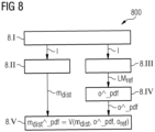
- FIG 8 a flow chart 800 is illustrated, which is related to the method according to a third embodiment of the invention, wherein a chest X-ray exam is carried out.
- step 8.1 chest X-ray images I are acquired from a patient.
- step 8.II the positioning of an external device (e.g. line) in the chest X-ray images I is checked.
- the measurement value m dist relates to the distance between the line's tips and anatomical structures, for example the carina, to, for example, compare device locations in sequential examinations. Such an examination is highly relevant in practice.
- step 8.III reference landmarks LM ref are obtained from the chest X-ray images I.
- step 8.IV the rotation and tilting information o ⁇ _pdf is determined based on the reference landmarks LM ref of the current 2D image I as it is done in clinical routine. For instance, distances between sternoclavicular joints and spine in chest X-ray images are used to estimate patient rotation o ⁇ _pdf.
- step 8.V the distance m dist ⁇ _pdf as if there would be no rotation is determined by transforming one pdf, which is related to the measured distances m dist in actual X-ray image to another pdf, which is related to the measured distances m dist ⁇ _pdf as if there would be no rotation.
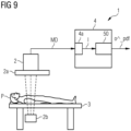
- FIG 9 shows an X-ray imaging system 1, which comprises the correction device 50 shown in FIG 5 in detail.
- the X-ray imaging system 1 essentially consists of a conventional acquisition unit 2 comprising an X-ray detector 2a and an X-ray source 2b opposite the X-ray detector 2a. Further, there is a patient table 3, the upper part of which with a patient P on it can be moved to the acquisition unit 2 in order to position the patient P under the X-ray detector 2a.
- the acquisition unit 2 and the patient table 3 are controlled by a control device 4, from which acquisition control signals (not shown in Fig 9 ) come for controlling the imaging process and which receives measuring data MD from the X-ray detector 2a.
- the control unit 4 also comprises a post-processing unit 4a for generating post-processed 2D medical image data I based on the received measuring data MD.
- the control unit 4 also includes the above-mentioned correction device 50 according to the invention.
- the medical image data I are analyzed by the correction device 50 and results o ⁇ _pdf are stored in a data storage unit (not shown in FIG 9 ) .
- the components of the correction device 50 can be implemented predominantly or completely in the form of software elements on a suitable processor.
- the interfaces between these components can also be designed purely in terms of software. All that is required is that there are access options to suitable storage areas in which the data can be stored temporarily and called up and updated at any time.
Landscapes
- Engineering & Computer Science (AREA)
- Physics & Mathematics (AREA)
- Theoretical Computer Science (AREA)
- General Physics & Mathematics (AREA)
- Computer Vision & Pattern Recognition (AREA)
- Nuclear Medicine, Radiotherapy & Molecular Imaging (AREA)
- Quality & Reliability (AREA)
- Radiology & Medical Imaging (AREA)
- Health & Medical Sciences (AREA)
- Medical Informatics (AREA)
- General Health & Medical Sciences (AREA)
- Geometry (AREA)
- Life Sciences & Earth Sciences (AREA)
- Bioinformatics & Cheminformatics (AREA)
- Bioinformatics & Computational Biology (AREA)
- Evolutionary Biology (AREA)
- Probability & Statistics with Applications (AREA)
- Apparatus For Radiation Diagnosis (AREA)
Abstract
Description
- The invention relates to a method for correcting geometric measurement values. The invention also concerns a correction device. Further, the invention relates to a medical imaging system.
- Two-dimensional (abbreviated: 2D) X-ray images are commonly used for measurements. For this purpose, usually anatomical or non-anatomical, for example, device based, landmarks are identified in the image and distance and/or angles are measured. However, the location of the landmarks in the 2D image can change based on a three-dimensional (abbreviated: 3D) orientation of an organ being examined. Thus, also the measurement values can change based on the 3D orientation of the organ.
- A dependency of the 2D measurement value on the 3D organ orientation poses certain problems:
A non-standard 3D organ orientation in a patient's X-ray exam can bias the measurement values and negatively impact comparison of these values to values from existing guidelines. - When follow-up exams of the same patient are acquired in different 3D organ orientation the resulting difference in measurement value may be misinterpreted as being caused by an actual anatomical change.
- Studies have shown that for a long-leg X-ray exam, the rotation of the limb, knee or foot have statistically significant impact on the measurement values. As an example, the study by Jamali et al (2017), "Do small changes in rotation affect measurements of lower extremity limb alignment?", Journal of Orthopaedic Surgery and Research, 12:77, https://doi.org/10.1186/s13018-017-0571-6 indicates that for some parameters, even a 3° rotational deviation can lead to a statistically significantly different value. Such different values are illustrated in
FIG 1 , which is taken from Jamali et al. - Hence there is a problem of a deviation of measurement values of 2D medical images.
- The before-mentioned problem is solved by a method for correcting a 2D measurement value according to
claim 1, by a correction device according toclaim 12 and by a medical imaging system according to claim 13. - According to the method for correcting a 2D measurement value, 2D image data, preferably X-ray image data, of an examination object are received, for example from a data source or an X-ray imaging system.
- The 2D measurement value to be corrected is taken from the 2D image data. Preferably, the 2D measurement value comprises a measurement value of a part of the body of a patient. For example, in case an image is taken from the lower limb of a patient, the measurement value can comprise at least one of the measurement values like mLDFA, MPTA, mTFA, aTFA, AMA and aLDFA as illustrated in
FIG 1 . - The 2D measurement value based on the 2D image data may deviate from the correct 2D measurement value, since the orientation of the examination object in the 2D image data may differ from a reference orientation. Further, landmarks are detected in the 2D image data and the 2D positions of the landmarks are estimated. In this context, it has to be mentioned that a landmark is assigned to an unambiguous position in the 2D image data. Furthermore, the corrected 2D measurement value of the examination object is predicted using a trained model, which depends on the received 2D image data, the estimated 2D positions of the landmarks and a reference parameter of a reference 3D orientation of the examination object. As later discussed in detail, the corrected measurement value comprises preferably a statistical quantity, i.e. a probability density function.
- For explaining the method in more details, we set some definitions:
Firstly, we define a transformation from 3D domain to 2D domain:
- Thereby, o are the 3D orientation parameters of the examination object, for example an organ, also named organ orientation parameters, in an object-specific coordinate system, r are the 3D positions of organ landmarks and P is the projection from 3D to 2D.
- Secondly, we define a transformation from 2D positions of landmarks to 2D measurement:

- Thereby, a are the 2D positions of organ landmarks, i.e. landmarks of the examination object, M is the 2D measurement definition and m is the 2D measurement value.
- From equation (1) and (2), it can be taken that the 2D measurement value m is a function of the 3D orientation parameters o.
- If the 3D orientation parameters o of the examination object are different from the reference orientation parameters due to a specific anatomy and indication, we would like to know, how the 2D measurement value m would be, if the examination object would have been positioned in the reference position.
- Thus, a model Z is defined that predicts measurement values for different organ orientation parameters.
- Formally, we define the corrected measurement value:

- Advantageously, the method according to the invention supplies a kind of support for a doctor for estimating a measurement value m of an examination object, for example an organ, based on an automatically determined orientation o and a reference orientation oref.
- The data correction device according to the invention comprises an input interface unit for receiving 2D image data of an examination object, a landmark detection unit for detecting landmarks in the 2D image data and estimating the 2D positions of the landmarks and a prediction unit for predicting a corrected measurement value of the examination object using a trained model, which depends on the received 2D image data, the estimated 2D positions of the landmarks and a reference parameter of a reference 3D orientation of the examination object. The correction device shares the advantages of the method for correcting a 2D measurement value according to the invention.
- The medical imaging system, preferably an X-ray imaging system, according to the invention comprises an acquisition unit for acquiring measuring data, i.e. raw data, from an examination object, a post-processing unit for generating post-processed image data based on the acquired measuring data and a correction device according to the invention. The medical imaging system shares the advantages of the correction device according to the invention.
- The essential components of the correction device according to the invention can for the most part be designed in the form of software components. This applies in particular to the landmark detection unit and the prediction unit of the correction device, but also parts of the input interface. In principle, however, some of these components can also be implemented in the form of software-supported hardware, for example FPGAs or the like, especially when it comes to particularly fast calculations. Likewise, the required interfaces, for example if it is only a matter of transferring data from other software components, can be designed as software interfaces. However, they can also be designed as hardware-based interfaces that are controlled by suitable software. Furthermore, some parts of the above-mentioned components may be distributed and stored in a local or regional or global network or a combination of a network and software, in particular a cloud system.
- A largely software-based implementation has the advantage that medical imaging systems that have already been used, can easily be retrofitted by a software update in order to work in the manner according to the invention. In this respect, the object is also achieved by a corresponding computer program product with a computer program that can be loaded directly into a memory device of, for example, a medical imaging system, with program sections, in order to carry out all steps of the method according to the invention, if the program is executed in the medical imaging system. In addition to the computer program, such a computer program product may contain additional components such as a documentation and/or additional components, including hardware components such as hardware keys (dongles etc.) for using the software.
- For transport to the medical imaging system and/or for storage on or in the medical imaging system, a computer-readable medium, for example a memory stick, a hard disk or some other transportable or permanently installed data carrier is used on which the program sections of the computer program that can be read in and executed by a computer unit of the AI-based analysis system are stored. The computer unit can comprise for example, one or more cooperating microprocessors or the like used for this purpose.
- The dependent claims and the following description each contain particularly advantageous embodiments and developments of the invention. In particular, the claims of one claim category can also be further developed analogously to the dependent claims of another claim category. In addition, within the scope of the invention, the various features of different exemplary embodiments and claims can also be combined to form new exemplary embodiments.
- In a variant of the method for correcting a 2D measurement value according to the invention the examination object comprises at least one of the following object types:
- an organ of a patient,
- a part of the body of a patient,
- a limb of a patient,
- a chest of a patient.
- In particular movable parts of the body like an upper or lower limb can be imaged from different rotation directions. In that context, it is very advantageous to correct measurement values such that they are comparable with a reference orientation.
- In case of the limb exam, in particular a lower limb X-ray exam, many different parameters can be measured, which depend on the limb rotation to a different extend. Often several exams are acquired of the same patient at different time points and the measurement values should be compared. Today, doctors make these measurements unassisted and may take limb rotation subjectively into account. To aid doctors and to make the measurements more objective, the method according to the invention can be applied in the following manner:
First, each X-ray image of a patient is measured conventionally based on the landmarks in the 2D image. A doctor sets the landmarks or, in a preferred scenario, an algorithm finds the landmarks. After that, the preliminary measurement values are calculated based on these 2D landmarks in the traditional way. In addition, based on the method according to the invention, the rotation of the limb, preferably the probability density function of the limb rotation, is estimated taking into account X-ray image data I and in further, the measurement values concerning to the lower limb, for example the MPTA, aTFA, aLDFA values, are predicted as if there was no limb rotation. Then, for transparency, the doctor can analyse both results, the uncorrected original measurement values and the corrected results, for example with 95% confidence interval. The doctor can then interpret the uncorrected or corrected values or an algorithm can support with the interpretation of the values. - In case of a chest X-ray exam the positioning of an external device, e.g. a line, in the chest X-ray images can be checked. Here, the measurement value relates to the distance between the line's tips and anatomical structures, for example the carina, to, for example, compare device locations in sequential examinations. Such an examination is highly relevant in practice. For estimating a rotation of the chest, reference landmarks are obtained from the chest X-ray images. Then, the rotation and tilting information is determined based on the reference landmarks of the current 2D image as it is done in clinical routine. For instance, distances between sternoclavicular joints and spine in chest X-ray images are used to estimate patient rotation. Having landmarks segmented as heatmaps, it is easily achievable to derive a probability distribution for the rotation of the chest using this approach. In that context, a linear transformation of normally distributed variables is used, which relates to a Gaussian probability density function. After that, the distance as if there would be no rotation is determined by transforming one probability distribution, which is related to the measured distances in actual X-ray image to another probability distribution, which is related to the measured distances as if there would be no rotation.
- In a further variant of the method for correcting a 2D measurement value according to the invention, the trained model comprises a first trained model and a second trained model to be carried out one after another. Advantageously, the subdivision into two separate tasks makes an automated correction possible.
- In another variant of the method for correcting a 2D measurement value according to the invention the input of the first model comprises the 2D image data and the output of the first model comprises the estimated 3D orientation parameters. To implement the first model, the concept of cross-modality training data generation can be employed. That means that images from one modality, e.g. a CT system, are used to generate a multitude of synthetic images similar to those of another modality, e.g. an X-ray imaging system, corresponding to different object orientation parameter values. Advantageously, the data basis for the training data does not need to be very extensive, since synthetic images with different parameters are generated based on a relatively small data basis.
- Further, the input for the second model comprises the estimated 3D orientation parameters, the reference parameter of a reference 3D orientation of the examination object and the 2D measurement value, depending on the estimated 2D positions to be corrected. The output of the second model comprises the corrected measurement value. To implement the second model, the concept of cross-modality training data generation can also be employed. By creation of synthetic X-ray images from the same CT volume with different 3D orientations, one can determine once: the 2D measurement value for the reference 3D orientation, and N times the 2D measurement value m for a 3D non-reference orientation. N is the number of synthetics X-ray images with other orientations. This enables to generate a multitude of synthetic X-ray images corresponding to different organ orientation parameters as a training data source. That approach is much easier to implement than a collection of this data by human annotation.
- The subdivision into two separate tasks, wherein the first task comprises the prediction of the actual organ orientation parameters from the image data and the second task comprises the transformation of the measurement value between two different organ orientation parameter values, makes an automated correction possible. It also makes the correction procedure transparent by providing an easy-to-interpret intermediate value to the human user.
- To do so, the task of model Z is subdivided into two separate tasks:
The first task is predicting actual organ orientation parameters from an X-ray image, i.e. 2D image data. - The second task is transforming measurement values between two values between two different organ orientation parameters.
- For prediction of organ orientation parameters from an X-ray image, it is defined:

- The model U can be implemented using a deep learning model with two possible approaches:
A first approach is an end-to-end regression approach. The second approach is a segmentation/ landmark detection approach followed by rule-based parameter estimation. - The prediction of a measurement value with reference organ orientation parameters can be defined as follows:

- In a further variant of the method for correcting a 2D measurement value according to the invention, the input of the second trained model comprises a difference between the estimated 3D orientation and the reference 3D orientation.
- A particular implementation of V is defined as follows:


- W is the model to predict a measurement value based on a difference d in 3D orientation parameters. Preferably, W is an AI (AI = artificial intelligence) based model, which can be generated by training an artificial neural network structure. A special variant of an AI based model comprises a deep learning model (abbreviated: DL model). Deep learning is part of a broader family of machine learning methods. The adjective "deep" in deep learning refers to the use of multiple layers in the network. Deep learning is appropriate for progressively extracting higher-level features from images.
- To implement the model W, again the concept of cross-modality training data generation can be employed. By creation of synthetic X-ray images from the same CT volume with different 3D orientations, one can create an extensive training data basis for training the model W.
- To train a model W that predicts a corrected measurement value m^_pdf based on a 2D measurement value m and the difference d = D(o^_pdf, oref), labelled training image data can be generated with the following parameters and orientations:
- Once: the estimated 2D measurement value or the corresponding possibility density function m^_pdf for the reference 3D orientation oref,
- N times: the 2D measurement value m for a 3D non-reference orientation o^_pdf.
- In a variant of the method for correcting a 2D measurement value according to the invention, the first trained model is trained by a multitude of synthetic X-ray images of the examination object corresponding to different 3D orientation parameters. As mentioned above, this approach is much easier to implement than a collection of these data by human annotation.
- The first trained model can be realized by an end-to-end approach. In this approach, the organ orientation parameters o^_pdf are predicted directly from the image. To train the model, for example a DL model, the concept of cross-modality training data generation can be employed. Tomographic images can be used to generate a multitude of synthetic X-ray images corresponding to different organ orientation parameters. Input data for the DL model training are the synthetic X-ray images, output of the DL model is the pdf of the organ orientation parameters o^_pdf.
- Alternatively, the first trained model comprises the step of carrying out the segmentation, which is trained by a multitude of synthetic X-ray images, wherein the output of the model is a label mask with segmentations.
- Then, preferably, measurement values are derived from the positions of anatomical structures in the label mask and the 3D orientation parameters are determined based on the measurement values.
- This variant is also named the segmentation approach.
- In this approach first relevant anatomical structures are segmented, and the locations of these structures are used to predict the organ orientation parameters o^_pdf based on measurements. Input data for the model training are the synthetic X-ray images, output of the model is a label mask with the pixel-level segmentations. From the label mask, measurements are made to predict a pdf of the organ orientation parameters o^_pdf.
- As an example, the following mathematical equation is suggested to predict the knee rotation based on a segmentation of the fibula and tibia:

- To train the model, again the concept of cross-modality training data generation can be employed, as described above. Segmentation of anatomical structures can be carried out in the domain of the CT images and segmentations can be forward projected onto 2D.
- This approach is more robust and has better transparency for a human compared to the end-to-end regression approach. In a further variant of the method for correcting a 2D measurement value according to the invention, the step of estimating the 3D orientation parameters comprises segmenting anatomical structures of the 2D image data and localizing these segmented anatomical structures and predicting the 3D orientation parameters based on the positions of the localized anatomical structures. In this preferred variant, the determining of the orientation parameters is divided in a plurality of separated tasks, wherein the first step of a segmentation is based on a trained model. Advantageously, the results of the model can be more easily validated by a doctor than compared to a variant, wherein the orientation parameters are estimated a single step.
- In a further variant of the method for correcting a measurement value according to the invention, the estimation of 3D orientation parameters in the 2D image data comprises an estimation of a probability density function o^_pdf of the 3D orientation parameters in the 2D image. Advantageously, a confidence interval can be indicated, which supplies an additional information about the reliability of the estimated orientation value.
- In a further variant of the method for correcting a measurement value according to the invention, the prediction of the corrected measurement value of the examination object comprises the determination of a probability density function m^_pdf of the corrected measurement value.
- Advantageously, a confidence interval can be indicated, which supplies an additional information about the reliability of the corrected measurement value.
- The invention is explained below with reference to the figures enclosed once again. The same components are provided with identical reference numbers in the various figures. The figures are usually not to scale.
-
FIG 1 shows some exemplary illustrations of medical images of limbs and related measurement values depending on the orientation of the limbs in the medical images, -
FIG 2 shows a flow chart diagram illustrating the method for correcting a 2D measurement value according to an embodiment of the invention, -
FIG 3 shows a flow chart diagram illustrating step 2.IV depicted inFIG 2 , -
FIG 4 shows a flow chart diagram illustrating step 2.V depicted inFIG 2 , -
FIG 5 shows a schematic view on a correction device according to an embodiment of the invention, -
FIG 6 shows a flow chart diagram illustrating the method for correcting a 2D measurement value according to a second embodiment of the invention, -
FIG 7 shows a schematic view on a table related to a comparison of original values, i.e. preliminary measurement values m with corrected measurement values for lower limb image data, -
FIG 8 shows a flow chart diagram illustrating the method for correcting a 2D measurement value according to a third embodiment of the invention, -
FIG 9 shows a schematic view on an X-ray imaging system according to an embodiment of the invention. - In
FIG 1 , achart 10, illustrating measurement values related to six different measurement methods of different common parameters of lower extremity alignment is depicted. On the left side, the different measurement methods are illustrated under the letters A, B, C, E, F, G. - The letter A is assigned to the mLDFA measurement, which provides a measurement value of a mechanical lateral distal femoral angle, abbreviated with mLDFA. That measurement value mLDFA is defined as the lateral angle between the femoral mechanical axis and the distal femoral articular axis.
- The letter B is assigned to the MPTA measurement, which provides the measurement value of the medial proximal tibial angle. That measurement value MPTA is defined as the medial angle between the mechanical axis of the tibia and the proximal tibial articular axis.
- The letter C is assigned to the mTFA measurement, which provides the measurement value of the mechanical tibiofemoral angle. That measurement value is defined as the angle between the femoral mechanical axis and the tibial mechanical axis with a positive value indicative of a valgus alignment and a negative value indicative of a varus alignment of the lower extremity.
- The letter E is assigned to the aTFA measurement value, which provides the measurement value of the anatomic tibiofemoral angle. That measurement value is defined as the angle between the anatomical axis of the femur and the anatomical-mechanical axis of the tibia. A positive value is indicative of a valgus and a negative value is indicative of a varus alignment of the lower extremity.
- The letter F is assigned to the AMA measurement value, which provides the measurement value of the angle between the mechanical and anatomical axes of the femur.
- The letter G is assigned to the aLDFA measurement value, which provides the measurement value of the angle between the anatomical axis of the femur and the distal femoral articular axis.
- On the right side of
FIG 1 , measurement values m in degree are shown related to different rotations of the lower limb in the corresponding X-ray images. "IR" means internal rotation and is related to negative values of the rotation of the lower extremity and "ER" means external rotation of the lower extremity and is related to positive values of the rotation of the lower extremity. Dashed bars are concerned to values with a significant difference relative to the baseline of 0° measurement. As can be taken fromFIG 1 , the measurement values of the MPTA, mTFA, aTFA and AMA measurement significantly depend on the orientation of the lower extremity in the X-ray image. Further information about the effect of rotation on various measured parameters of lower extremity alignment can be read in Jamali et al., "Do small changes in rotation affect measurements of lower extremity limb alignment?", Journal of Orthopaedic Surgery and Research (2017) 12:77 DOI 10.1186/s13018-0571-6. -
FIG 2 shows a flow chart diagram 200 illustrating the method for correcting a 2D measurement value according to an embodiment of the invention. - In step 2.1, 2D image data I of an examination object, in that special embodiment, a lower extremity, are received from a
post-processing unit 4a (shown inFIG 9 ). - In step 2.II, landmarks LM are detected in the 2D image data I, wherein the 2D positions a of the landmarks LM are estimated.
- In step 2.III, a preliminary measurement value m, for example the MPTA value m is calculated based on the 2D positions a of the landmarks LM. As above-mentioned, due to a possible deviation of the lower limb rotation in the 2D image data compared to a reference rotation, the measurement value m may deviate from a corrected value m^ .
- In step 2.IV, a probability density function o^_pdf of the 3D orientation parameters, i.e. the lower limb rotation, is determined based on the image data I of the lower extremity. Details of the determination of the function o^_pdf are discussed in context with
FIG 3 . - In step 2.V, a probability density function m^_pdf of a corrected measurement value m^ is determined based on the preliminary measurement value m, the probability density function o^_pdf of the 3D orientation parameters o and the reference orientation oref. Details of the calculation of the probability density function m^_pdf of a corrected measurement value m^ are discussed in context with
FIG 4 . - In
FIG 3 , a flow chart diagram 300 is shown, which illustrates details of the determination of the function o^_pdf in step 2.IV. - In step 2.IVa, a segmentation of the image data I is carried out. For that purpose a trained model is used to predict a label mask with pixel-level segmentations LMSK.
- Then in step 2.IVb, from the label mask LMSK, measurement values mv are determined for later predicting the probability density function o^_pdf of the orientation of the examined object.
- For example, the examined object is the lower limb and the orientation o^ of the lower limb, also named as rotation of the knee, can be calculated based on formula (8). The measurement values mv comprise a first measurement value mv1, a second measurement value mv2 and a third measurement value mv3, wherein mv1 = the visible part of the fibula(%), mv2 = the overlapped part of the fibular tip(%), mv3 = distance between the fibular tip and the lateral fibular cortex(%).
- To train the model of step 2.IVa, for example a Deep Learning model, the concept of cross-modality training data generation can be employed as described above. Segmentation of anatomical structures can be carried out in the domain of CT images and segmentations can then be forward projected onto 2D image data.
- In step 2.IVc the probability density function o^_pdf of an orientation of the knee is determined based on formula (8).
- In
FIG 4 , a flow chart diagram 400 is shown, which illustrates details of the determination of the probability density function m^_pdf of the corrected measurement value, in the specific embodiment, the MPTA value of the lower limb in step 2.V. - In step 2.Va, based on the probability density function o^_pdf of an orientation of the knee and a reference orientation value oref, a difference d is determined. In the simplest case the difference value d is a difference between two scalar values, for example the measured and the reference rotation value of the knee.
- In step 2.Vb, the probability density function m^_pdf of a corrected measurement value m^ is calculated based on the determined difference value d and the preliminary measurement value m, using a trained model W.
- To implement the model W, again the concept of cross-modality training data generation can be employed. By creation of synthetic X-ray images from the same CT volume with different 3D orientations one can determine once, the 2D measurement value m^_pdf for the reference 3D orientation oref and N times, the 2D measurement value m for a 3D non-reference orientation o^_pdf, to train the model W.
- In
FIG 5 , a schematic view on acorrection device 50 is illustrated. Thecorrection device 50 comprises aninput interface unit 51 for receiving 2D image data I of an examination object, for example the 2D image data of a lower limb. Thecorrection device 50 also comprises alandmark detection unit 52 for detecting landmarks LM in the 2D image data I and for estimating the 2D positions a of the landmarks LM. Thecorrection device 50 also encompasses a preliminary measurementvalue determination unit 53 for determining a preliminary measurement value m based on the estimation of the 2D positions a of the landmarks LM. Thecorrection device 50 further comprises anorientation prediction unit 54a for determining a probability density function o^_pdf of an orientation of the examined object. The probability density function o^_pdf is determined based on a trained model, for example a Deep Learning model. - The
correction device 50 further includes a measurementvalue prediction unit 54b for predicting a corrected measurement value m^_pdf of the examination object based on the probability density function o^_pdf of an orientation of the examined object and the preliminary measurement value m using a trained model. - In
FIG 6 , aflow chart 600 is illustrated, which is related to the method according to a second embodiment of the invention, wherein a lower limb X-ray exam is carried out. - In a lower limb X-ray exam, many different parameters can be measured, which depend on the limb rotation to a different extend, as illustrated in
FIG 1 . Often, several exams are acquired of the same patient at different time points and the measurement values should be compared. Today, doctors make these measurements unassisted and may take limb rotation subjectively into account. To aid doctors and to make the measurements more objective, the following sequence of steps is proposed. - In step 6.1, each X-ray image of a patient is measured conventionally based on the landmarks in the 2D image. A doctor sets the landmarks LM or, in a preferred scenario, an algorithm finds the landmarks.
- In step 6.II, the preliminary measurement values m are calculated based on these 2D landmarks LM in the traditional way.
- In step 6.III, in addition, based on the method according to the invention, the probability density function o^_pdf of the limb rotation is estimated taking into account X-ray image data I and in step 6.IV, the measurement values m^_pdf concerning to the lower limb, for example the MPTA, aTFA, aLDFA values are predicted as if there was no limb rotation.
- Then in step 6.V, for transparency, the doctor analyses both results. The uncorrected original measurement values m and the corrected results m^_pdf with 95% confidence interval.
- The doctor can then interpret the uncorrected or corrected values or an algorithm can support with the interpretation of the values.
- In
FIG 7 , a table is shown, which compares original values, i.e. preliminary measurement values m with corrected measurement values m^_pdf for lower limb image data and a confidence interval CI. The estimated limb rotation of the image data is +10°. The measurement values m, m^ relate to MPTA, aTFA and aLDFA measurement values. As can be taken from the table inFIG 7 , the corrected MPTA value and the corrected aTFA value significantly differ from the corresponding measured value. - In
FIG 8 , aflow chart 800 is illustrated, which is related to the method according to a third embodiment of the invention, wherein a chest X-ray exam is carried out. - In the third embodiment, in step 8.1 chest X-ray images I are acquired from a patient. In step 8.II the positioning of an external device (e.g. line) in the chest X-ray images I is checked. Here, the measurement value mdist relates to the distance between the line's tips and anatomical structures, for example the carina, to, for example, compare device locations in sequential examinations. Such an examination is highly relevant in practice.
- In step 8.III, reference landmarks LMref are obtained from the chest X-ray images I.
- In step 8.IV, the rotation and tilting information o^_pdf is determined based on the reference landmarks LMref of the current 2D image I as it is done in clinical routine. For instance, distances between sternoclavicular joints and spine in chest X-ray images are used to estimate patient rotation o^_pdf.
- Having landmarks LMref segmented as heatmaps, it is straightforward to derive a probability o^_pdf distribution using this approach. In that context, a linear transformation of normally distributed variables is used, which relates to a Gaussian probability density function o^_pdf.
- In step 8.V, the distance mdist^_pdf as if there would be no rotation is determined by transforming one pdf, which is related to the measured distances mdist in actual X-ray image to another pdf, which is related to the measured distances mdist^_pdf as if there would be no rotation.
-
FIG 9 shows anX-ray imaging system 1, which comprises thecorrection device 50 shown inFIG 5 in detail. TheX-ray imaging system 1 essentially consists of aconventional acquisition unit 2 comprising anX-ray detector 2a and anX-ray source 2b opposite theX-ray detector 2a. Further, there is a patient table 3, the upper part of which with a patient P on it can be moved to theacquisition unit 2 in order to position the patient P under theX-ray detector 2a. Theacquisition unit 2 and the patient table 3 are controlled by acontrol device 4, from which acquisition control signals (not shown inFig 9 ) come for controlling the imaging process and which receives measuring data MD from theX-ray detector 2a. Thecontrol unit 4 also comprises apost-processing unit 4a for generating post-processed 2D medical image data I based on the received measuring data MD. - The
control unit 4 also includes the above-mentionedcorrection device 50 according to the invention. The medical image data I are analyzed by thecorrection device 50 and results o^_pdf are stored in a data storage unit (not shown inFIG 9 ) . - The components of the
correction device 50 can be implemented predominantly or completely in the form of software elements on a suitable processor. In particular, the interfaces between these components can also be designed purely in terms of software. All that is required is that there are access options to suitable storage areas in which the data can be stored temporarily and called up and updated at any time. - Further, the use of the undefined article "a" or "one" does not exclude that the referred features can also be present several times. Likewise, the term "unit" or "device" does not exclude that it consists of several components, which may also be spatially distributed.
Claims (15)
- Method for correcting a 2D measurement value (m), comprising the steps of:- receiving 2D image data (I) of an examination object,- detecting landmarks (LM) in the 2D image data (I) wherein 2D positions (a) of the landmarks (LM) are estimated,- predicting a corrected measurement value (m^_pdf) of the examination object using a trained model (Z(a, I, oref)), which depends on the received 2D image data (I), the estimated 2D positions (a) of the landmarks (LM) and a reference parameter (oref) of a reference 3D orientation of the examination object.
- Method according to claim 1, wherein the examination object comprises at least one of the following object types:- an organ of a patient (P),- a part of the body of a patient (P),- a limb of a patient (P),- a chest of a patient (P).
- Method according to claim 1 or 2, wherein the trained model (Z(a, I, oref)) comprises a first trained model (U(I)) and a second trained model (V(m, o^_pdf, oref)) to be carried out one after another.
- Method according to claim 3, wherein- the input of the first trained model (U(I)) comprises the 2D image data (I) and- the output of the first trained model (U(I)) comprises estimated 3D orientation parameters (o^_pdf).
- Method according to claim 3 or 4, wherein- the input for the second trained model (V(m, o^_pdf, oref)) comprises- the estimated 3D orientation parameters (o^_pdf),- the reference parameters (oref) of a reference 3D-orientation of the examination object and- a 2D measurement value (m), depending on the estimated 2D positions (a), to be corrected, and- the output of the second trained model (V(m, o^_pdf, oref)) comprises the corrected measurement value (m^_pdf).
- Method according to one of the claims 3 to 5, wherein the input of the second trained model (V(m, o^_pdf, oref)) comprises a difference D(o^_pdf, oref) between the estimated 3D orientation (o^_pdf) and the reference 3D orientation (oref).
- Method according to one of the claims 3 to 6, wherein the first trained model (U(I)) is trained by a multitude of synthetic 2D images of the examination object corresponding to different 3D orientation parameters (o^_pdf).
- Method according to one of the preceding claims, wherein the step of estimating the 3D orientation parameters (o^_pdf) comprises:- segmenting anatomical structures of the 2D image data (I) and localizing the segmented anatomical structures (LM),- predict 3D orientation parameters (o^_pdf) based on the positions (a) of the localized segmented anatomical structures (LM).
- Method according to claim 8, wherein the first trained model (U(I)) comprises the step of carrying out the segmentation, which is trained by a multitude of synthetic 2D images, wherein the output of the model (U(I)) comprises a label mask (LMSK) with segmentations.
- Method according to claim 9, wherein- measurement values concerning the positions of anatomical structures are taken from the label mask (LMSK) and- the 3D orientation parameters (o^_pdf) are determined based on the measurement values.
- Method according to one of the preceding claims, wherein- the estimation of the 3D orientation parameters (o^_pdf) in the 2D image data (I) comprises an estimation of a probability density function of the 3D orientation parameters (o^_pdf) in the 2D-image and/or- the prediction of the corrected measurement value (m^_pdf) of the examination object comprises the determination of a probability density function (m^_pdf) of the corrected measurement value.
- Correction device (50) for, comprising:- an input interface unit (51) for receiving 2D image data (I) of an examination object,- a landmark detection unit (52) for detecting landmarks (LM) in the 2D image data (I) and for estimating the 2D positions (a) of the landmarks (LM),- a prediction unit (54a, 54b) for predicting a corrected measurement value (m^_pdf) of the examination object using a trained model (Z(a, I, oref)), which depends on the received 2D image data (I), the estimated 2D positions (a) of the landmarks (LM) and a reference parameter (oref) of a reference 3D orientation of the examination object.
- A medical imaging system (1), comprising:- an acquisition unit (2) for acquiring measuring data (MD) from an examination object (P),- a post-processing unit (4a) for generating post-processed 2D image data (I) based on the acquired measuring data (MD),- a correction device (50) according to claim 12.
- Computer program product with a computer program, which can be loaded directly into a memory device of a medical imaging system (1), with program sections to perform all the steps of the method according to anyone of the claims 1 to 11, when the computer program is carried out in the medical imaging system (1).
- Computer readable medium, on which program sections that can be read in and executed by a computer unit are stored in order to carry out all steps of the method according to anyone of the claims 1 to 11, when the program sections are executed by the computer unit.
Priority Applications (3)
| Application Number | Priority Date | Filing Date | Title |
|---|---|---|---|
| EP21198444.8A EP4156088B1 (en) | 2021-09-23 | 2021-09-23 | Correction of geometric measurement values from 2d projection images |
| US17/948,454 US20230090411A1 (en) | 2021-09-23 | 2022-09-20 | Correction of geometric measurement values from 2d projection images |
| CN202211150874.6A CN115861459A (en) | 2021-09-23 | 2022-09-21 | Correction of geometric measurements from 2D projection images |
Applications Claiming Priority (1)
| Application Number | Priority Date | Filing Date | Title |
|---|---|---|---|
| EP21198444.8A EP4156088B1 (en) | 2021-09-23 | 2021-09-23 | Correction of geometric measurement values from 2d projection images |
Publications (3)
| Publication Number | Publication Date |
|---|---|
| EP4156088A1 true EP4156088A1 (en) | 2023-03-29 |
| EP4156088B1 EP4156088B1 (en) | 2025-07-09 |
| EP4156088C0 EP4156088C0 (en) | 2025-07-09 |
Family
ID=77910655
Family Applications (1)
| Application Number | Title | Priority Date | Filing Date |
|---|---|---|---|
| EP21198444.8A Active EP4156088B1 (en) | 2021-09-23 | 2021-09-23 | Correction of geometric measurement values from 2d projection images |
Country Status (3)
| Country | Link |
|---|---|
| US (1) | US20230090411A1 (en) |
| EP (1) | EP4156088B1 (en) |
| CN (1) | CN115861459A (en) |
Families Citing this family (2)
| Publication number | Priority date | Publication date | Assignee | Title |
|---|---|---|---|---|
| AU2022316594A1 (en) * | 2021-07-28 | 2024-02-08 | Artrya Limited | A coronary artery disease analysis system |
| CN117830305B (en) * | 2024-03-04 | 2024-05-03 | 腾讯科技(深圳)有限公司 | Object measurement method, device, equipment and medium |
Citations (1)
| Publication number | Priority date | Publication date | Assignee | Title |
|---|---|---|---|---|
| US20210007806A1 (en) * | 2018-03-21 | 2021-01-14 | Vikas KARADE | A method for obtaining 3-d deformity correction for bones |
Family Cites Families (2)
| Publication number | Priority date | Publication date | Assignee | Title |
|---|---|---|---|---|
| TWI607412B (en) * | 2016-09-10 | 2017-12-01 | 財團法人工業技術研究院 | Measurement systems and methods for measuring multi-dimensions |
| JP7787654B2 (en) * | 2021-06-11 | 2025-12-17 | Astemo株式会社 | Appearance inspection device, appearance inspection method, image generation device, and image generation method |
-
2021
- 2021-09-23 EP EP21198444.8A patent/EP4156088B1/en active Active
-
2022
- 2022-09-20 US US17/948,454 patent/US20230090411A1/en active Pending
- 2022-09-21 CN CN202211150874.6A patent/CN115861459A/en active Pending
Patent Citations (1)
| Publication number | Priority date | Publication date | Assignee | Title |
|---|---|---|---|---|
| US20210007806A1 (en) * | 2018-03-21 | 2021-01-14 | Vikas KARADE | A method for obtaining 3-d deformity correction for bones |
Non-Patent Citations (5)
| Title |
|---|
| JAMALI AMIR A. ET AL: "Do small changes in rotation affect measurements of lower extremity limb alignment?", JOURNAL OF ORTHOPAEDIC SURGERY AND RESEARCH, vol. 12, no. 1, 22 May 2017 (2017-05-22), XP055891640, Retrieved from the Internet <URL:http://link.springer.com/content/pdf/10.1186/s13018-017-0571-6.pdf> [retrieved on 20220225], DOI: 10.1186/s13018-017-0571-6 * |
| JAMALI ET AL.: "Do small changes in rotation affect measurements of lower extremity limb alignment?", JOUR NAL OF ORTHOPAEDIC SURGERY AND RESEARCH, vol. 12, 2017, pages 77 |
| JAMALI ET AL.: "Do small changes in rotation affect measurements of lower extremity limb alignment?", JOURNAL OF, vol. 12, 2017, pages 77, Retrieved from the Internet <URL:https://doi.org/10.1186/s13018-017-0571-6> |
| KWOLEK KAMIL ET AL: "Measuring Lower Limb Alignment and Joint Orientation Using Deep Learning Based Segmentation of Bones", 26 August 2019, ADVANCES IN DATABASES AND INFORMATION SYSTEMS; [LECTURE NOTES IN COMPUTER SCIENCE; LECT.NOTES COMPUTER], SPRINGER INTERNATIONAL PUBLISHING, CHAM, PAGE(S) 514 - 525, ISBN: 978-3-319-10403-4, XP047518649 * |
| MADER-BACHER ET AL.: "Predicting knee rotation by the projection overlap of the proximal fibula and tibia in long-leg radiographs", KNEE SURG SPORTS TRAUMATOL ARTHROSC, vol. 22, 2014, pages 2982 - 2988, Retrieved from the Internet <URL:http://doi.org/10.1007/s00167-014-3327-4> |
Also Published As
| Publication number | Publication date |
|---|---|
| US20230090411A1 (en) | 2023-03-23 |
| CN115861459A (en) | 2023-03-28 |
| EP4156088B1 (en) | 2025-07-09 |
| EP4156088C0 (en) | 2025-07-09 |
Similar Documents
| Publication | Publication Date | Title |
|---|---|---|
| JP7466928B2 (en) | Artificial intelligence intraoperative surgical guidance systems and methods of use | |
| Ma et al. | Multimodal image registration with deep context reinforcement learning | |
| EP2603136B1 (en) | Detection of anatomical landmarks | |
| US11141225B2 (en) | Image matching device and image matching method | |
| US7929745B2 (en) | Method and system for characterization of knee joint morphology | |
| EP2996599B1 (en) | Planning methods for surgical correction of abnormal bones | |
| US20240206990A1 (en) | Artificial Intelligence Intra-Operative Surgical Guidance System and Method of Use | |
| US11410769B1 (en) | Tactile solutions integration for patient specific treatment | |
| Zhu et al. | Construction of 3D human distal femoral surface models using a 3D statistical deformable model | |
| Jensen et al. | Joint track machine learning: an autonomous method of measuring total knee arthroplasty kinematics from single-plane X-ray images | |
| EP4156088B1 (en) | Correction of geometric measurement values from 2d projection images | |
| Kordon et al. | Multi-task localization and segmentation for x-ray guided planning in knee surgery | |
| Phan et al. | Predicting anatomical landmarks and bone morphology of the femur using local region matching | |
| Cerveri et al. | Automated method for computing the morphological and clinical parameters of the proximal femur using heuristic modeling techniques | |
| Casciaro et al. | Towards automatic measurement of anteversion and neck–shaft angles in human femurs using CT images | |
| Seise et al. | Learning active shape models for bifurcating contours | |
| Ebsim et al. | Detection of wrist fractures in X-ray images | |
| Mekhzoum et al. | Towards point cloud-based medical image registration for dynamic 4d-ct imaging | |
| Krönke et al. | CNN-based pose estimation for assessing quality of ankle-joint X-ray images | |
| Facente et al. | Multi-stage CNN for fast registration of 3D preoperative CTs to 2D intraoperative X-rays | |
| Cerveri et al. | Determination of the Whiteside line on femur surface models by fitting high-order polynomial functions to cross-section profiles of the intercondylar fossa | |
| Motesharei et al. | Assessing concordance in post-operative knee implant position analysis between automated image analysis algorithm and human radiologists | |
| Neiss-Theuerkauff et al. | Semantic bone structure segmentation in 2D image data: towards total knee arthroplasty | |
| Guo et al. | Surface-based rigid registration using a global optimization algorithm for assessment of MRI knee cartilage thickness changes | |
| Görres et al. | Articular surface segmentation using active shape models for intraoperative implant assessment |
Legal Events
| Date | Code | Title | Description |
|---|---|---|---|
| PUAI | Public reference made under article 153(3) epc to a published international application that has entered the european phase |
Free format text: ORIGINAL CODE: 0009012 |
|
| STAA | Information on the status of an ep patent application or granted ep patent |
Free format text: STATUS: THE APPLICATION HAS BEEN PUBLISHED |
|
| AK | Designated contracting states |
Kind code of ref document: A1 Designated state(s): AL AT BE BG CH CY CZ DE DK EE ES FI FR GB GR HR HU IE IS IT LI LT LU LV MC MK MT NL NO PL PT RO RS SE SI SK SM TR |
|
| STAA | Information on the status of an ep patent application or granted ep patent |
Free format text: STATUS: REQUEST FOR EXAMINATION WAS MADE |
|
| 17P | Request for examination filed |
Effective date: 20230905 |
|
| RBV | Designated contracting states (corrected) |
Designated state(s): AL AT BE BG CH CY CZ DE DK EE ES FI FR GB GR HR HU IE IS IT LI LT LU LV MC MK MT NL NO PL PT RO RS SE SI SK SM TR |
|
| RAP1 | Party data changed (applicant data changed or rights of an application transferred) |
Owner name: SIEMENS HEALTHINEERS AG |
|
| GRAP | Despatch of communication of intention to grant a patent |
Free format text: ORIGINAL CODE: EPIDOSNIGR1 |
|
| STAA | Information on the status of an ep patent application or granted ep patent |
Free format text: STATUS: GRANT OF PATENT IS INTENDED |
|
| INTG | Intention to grant announced |
Effective date: 20250307 |
|
| GRAS | Grant fee paid |
Free format text: ORIGINAL CODE: EPIDOSNIGR3 |
|
| GRAA | (expected) grant |
Free format text: ORIGINAL CODE: 0009210 |
|
| STAA | Information on the status of an ep patent application or granted ep patent |
Free format text: STATUS: THE PATENT HAS BEEN GRANTED |
|
| AK | Designated contracting states |
Kind code of ref document: B1 Designated state(s): AL AT BE BG CH CY CZ DE DK EE ES FI FR GB GR HR HU IE IS IT LI LT LU LV MC MK MT NL NO PL PT RO RS SE SI SK SM TR |
|
| REG | Reference to a national code |
Ref country code: GB Ref legal event code: FG4D |
|
| REG | Reference to a national code |
Ref country code: CH Ref legal event code: EP |
|
| REG | Reference to a national code |
Ref country code: IE Ref legal event code: FG4D |
|
| U01 | Request for unitary effect filed |
Effective date: 20250723 |
|
| U07 | Unitary effect registered |
Designated state(s): AT BE BG DE DK EE FI FR IT LT LU LV MT NL PT RO SE SI Effective date: 20250729 |
|
| U20 | Renewal fee for the european patent with unitary effect paid |
Year of fee payment: 5 Effective date: 20250919 |
|
| PG25 | Lapsed in a contracting state [announced via postgrant information from national office to epo] |
Ref country code: IS Free format text: LAPSE BECAUSE OF FAILURE TO SUBMIT A TRANSLATION OF THE DESCRIPTION OR TO PAY THE FEE WITHIN THE PRESCRIBED TIME-LIMIT Effective date: 20251109 |
|
| PGFP | Annual fee paid to national office [announced via postgrant information from national office to epo] |
Ref country code: GB Payment date: 20251002 Year of fee payment: 5 |
|
| PG25 | Lapsed in a contracting state [announced via postgrant information from national office to epo] |
Ref country code: NO Free format text: LAPSE BECAUSE OF FAILURE TO SUBMIT A TRANSLATION OF THE DESCRIPTION OR TO PAY THE FEE WITHIN THE PRESCRIBED TIME-LIMIT Effective date: 20251009 |
|
| PG25 | Lapsed in a contracting state [announced via postgrant information from national office to epo] |
Ref country code: HR Free format text: LAPSE BECAUSE OF FAILURE TO SUBMIT A TRANSLATION OF THE DESCRIPTION OR TO PAY THE FEE WITHIN THE PRESCRIBED TIME-LIMIT Effective date: 20250709 |
|
| PG25 | Lapsed in a contracting state [announced via postgrant information from national office to epo] |
Ref country code: GR Free format text: LAPSE BECAUSE OF FAILURE TO SUBMIT A TRANSLATION OF THE DESCRIPTION OR TO PAY THE FEE WITHIN THE PRESCRIBED TIME-LIMIT Effective date: 20251010 |
|
| PG25 | Lapsed in a contracting state [announced via postgrant information from national office to epo] |
Ref country code: PL Free format text: LAPSE BECAUSE OF FAILURE TO SUBMIT A TRANSLATION OF THE DESCRIPTION OR TO PAY THE FEE WITHIN THE PRESCRIBED TIME-LIMIT Effective date: 20250709 |
|
| PG25 | Lapsed in a contracting state [announced via postgrant information from national office to epo] |
Ref country code: RS Free format text: LAPSE BECAUSE OF FAILURE TO SUBMIT A TRANSLATION OF THE DESCRIPTION OR TO PAY THE FEE WITHIN THE PRESCRIBED TIME-LIMIT Effective date: 20251009 |
|
| PG25 | Lapsed in a contracting state [announced via postgrant information from national office to epo] |
Ref country code: ES Free format text: LAPSE BECAUSE OF FAILURE TO SUBMIT A TRANSLATION OF THE DESCRIPTION OR TO PAY THE FEE WITHIN THE PRESCRIBED TIME-LIMIT Effective date: 20250709 |
|
| PG25 | Lapsed in a contracting state [announced via postgrant information from national office to epo] |
Ref country code: SM Free format text: LAPSE BECAUSE OF FAILURE TO SUBMIT A TRANSLATION OF THE DESCRIPTION OR TO PAY THE FEE WITHIN THE PRESCRIBED TIME-LIMIT Effective date: 20250709 |
|
| PG25 | Lapsed in a contracting state [announced via postgrant information from national office to epo] |
Ref country code: CZ Free format text: LAPSE BECAUSE OF FAILURE TO SUBMIT A TRANSLATION OF THE DESCRIPTION OR TO PAY THE FEE WITHIN THE PRESCRIBED TIME-LIMIT Effective date: 20250709 |
|
| PG25 | Lapsed in a contracting state [announced via postgrant information from national office to epo] |
Ref country code: SK Free format text: LAPSE BECAUSE OF FAILURE TO SUBMIT A TRANSLATION OF THE DESCRIPTION OR TO PAY THE FEE WITHIN THE PRESCRIBED TIME-LIMIT Effective date: 20250709 |
|
| REG | Reference to a national code |
Ref country code: CH Ref legal event code: H13 Free format text: ST27 STATUS EVENT CODE: U-0-0-H10-H13 (AS PROVIDED BY THE NATIONAL OFFICE) Effective date: 20260504 |
|
| PLBE | No opposition filed within time limit |
Free format text: ORIGINAL CODE: 0009261 |
|
| STAA | Information on the status of an ep patent application or granted ep patent |
Free format text: STATUS: NO OPPOSITION FILED WITHIN TIME LIMIT |