EP4155744A1 - Device and method for diagnosing battery abnormality - Google Patents
Device and method for diagnosing battery abnormality Download PDFInfo
- Publication number
- EP4155744A1 EP4155744A1 EP21856155.3A EP21856155A EP4155744A1 EP 4155744 A1 EP4155744 A1 EP 4155744A1 EP 21856155 A EP21856155 A EP 21856155A EP 4155744 A1 EP4155744 A1 EP 4155744A1
- Authority
- EP
- European Patent Office
- Prior art keywords
- battery cell
- voltage
- battery
- abnormality
- diagnosing
- Prior art date
- Legal status (The legal status is an assumption and is not a legal conclusion. Google has not performed a legal analysis and makes no representation as to the accuracy of the status listed.)
- Granted
Links
Images




Classifications
-
- G—PHYSICS
- G01—MEASURING; TESTING
- G01R—MEASURING ELECTRIC VARIABLES; MEASURING MAGNETIC VARIABLES
- G01R31/00—Arrangements for testing electric properties; Arrangements for locating electric faults; Arrangements for electrical testing characterised by what is being tested not provided for elsewhere
- G01R31/36—Arrangements for testing, measuring or monitoring the electrical condition of accumulators or electric batteries, e.g. capacity or state of charge [SoC]
- G01R31/367—Software therefor, e.g. for battery testing using modelling or look-up tables
-
- G—PHYSICS
- G01—MEASURING; TESTING
- G01R—MEASURING ELECTRIC VARIABLES; MEASURING MAGNETIC VARIABLES
- G01R31/00—Arrangements for testing electric properties; Arrangements for locating electric faults; Arrangements for electrical testing characterised by what is being tested not provided for elsewhere
- G01R31/36—Arrangements for testing, measuring or monitoring the electrical condition of accumulators or electric batteries, e.g. capacity or state of charge [SoC]
- G01R31/392—Determining battery ageing or deterioration, e.g. state of health
-
- G—PHYSICS
- G01—MEASURING; TESTING
- G01R—MEASURING ELECTRIC VARIABLES; MEASURING MAGNETIC VARIABLES
- G01R31/00—Arrangements for testing electric properties; Arrangements for locating electric faults; Arrangements for electrical testing characterised by what is being tested not provided for elsewhere
- G01R31/36—Arrangements for testing, measuring or monitoring the electrical condition of accumulators or electric batteries, e.g. capacity or state of charge [SoC]
- G01R31/382—Arrangements for monitoring battery or accumulator variables, e.g. SoC
-
- G—PHYSICS
- G01—MEASURING; TESTING
- G01R—MEASURING ELECTRIC VARIABLES; MEASURING MAGNETIC VARIABLES
- G01R31/00—Arrangements for testing electric properties; Arrangements for locating electric faults; Arrangements for electrical testing characterised by what is being tested not provided for elsewhere
- G01R31/36—Arrangements for testing, measuring or monitoring the electrical condition of accumulators or electric batteries, e.g. capacity or state of charge [SoC]
- G01R31/382—Arrangements for monitoring battery or accumulator variables, e.g. SoC
- G01R31/3835—Arrangements for monitoring battery or accumulator variables, e.g. SoC involving only voltage measurements
-
- G—PHYSICS
- G08—SIGNALLING
- G08B—SIGNALLING SYSTEMS, e.g. PERSONAL CALLING SYSTEMS; ORDER TELEGRAPHS; ALARM SYSTEMS
- G08B21/00—Alarms responsive to a single specified undesired or abnormal condition and not otherwise provided for
- G08B21/18—Status alarms
- G08B21/185—Electrical failure alarms
-
- G—PHYSICS
- G01—MEASURING; TESTING
- G01R—MEASURING ELECTRIC VARIABLES; MEASURING MAGNETIC VARIABLES
- G01R31/00—Arrangements for testing electric properties; Arrangements for locating electric faults; Arrangements for electrical testing characterised by what is being tested not provided for elsewhere
- G01R31/36—Arrangements for testing, measuring or monitoring the electrical condition of accumulators or electric batteries, e.g. capacity or state of charge [SoC]
- G01R31/3644—Constructional arrangements
- G01R31/3648—Constructional arrangements comprising digital calculation means, e.g. for performing an algorithm
-
- G—PHYSICS
- G01—MEASURING; TESTING
- G01R—MEASURING ELECTRIC VARIABLES; MEASURING MAGNETIC VARIABLES
- G01R31/00—Arrangements for testing electric properties; Arrangements for locating electric faults; Arrangements for electrical testing characterised by what is being tested not provided for elsewhere
- G01R31/36—Arrangements for testing, measuring or monitoring the electrical condition of accumulators or electric batteries, e.g. capacity or state of charge [SoC]
- G01R31/382—Arrangements for monitoring battery or accumulator variables, e.g. SoC
- G01R31/3842—Arrangements for monitoring battery or accumulator variables, e.g. SoC combining voltage and current measurements
-
- G—PHYSICS
- G01—MEASURING; TESTING
- G01R—MEASURING ELECTRIC VARIABLES; MEASURING MAGNETIC VARIABLES
- G01R31/00—Arrangements for testing electric properties; Arrangements for locating electric faults; Arrangements for electrical testing characterised by what is being tested not provided for elsewhere
- G01R31/36—Arrangements for testing, measuring or monitoring the electrical condition of accumulators or electric batteries, e.g. capacity or state of charge [SoC]
- G01R31/396—Acquisition or processing of data for testing or for monitoring individual cells or groups of cells within a battery
-
- Y—GENERAL TAGGING OF NEW TECHNOLOGICAL DEVELOPMENTS; GENERAL TAGGING OF CROSS-SECTIONAL TECHNOLOGIES SPANNING OVER SEVERAL SECTIONS OF THE IPC; TECHNICAL SUBJECTS COVERED BY FORMER USPC CROSS-REFERENCE ART COLLECTIONS [XRACs] AND DIGESTS
- Y02—TECHNOLOGIES OR APPLICATIONS FOR MITIGATION OR ADAPTATION AGAINST CLIMATE CHANGE
- Y02E—REDUCTION OF GREENHOUSE GAS [GHG] EMISSIONS, RELATED TO ENERGY GENERATION, TRANSMISSION OR DISTRIBUTION
- Y02E60/00—Enabling technologies; Technologies with a potential or indirect contribution to GHG emissions mitigation
- Y02E60/10—Energy storage using batteries
Definitions
- the present invention relates to a battery abnormality diagnosis apparatus and method for diagnosing abnormality of a battery in an idle period.
- the secondary batteries which are chargeable/dischargeable batteries, may include all of conventional nickel (Ni)/cadmium (Cd) batteries, Ni/metal hydride (MH) batteries, etc., and recent lithium ion batteries.
- a lithium ion battery has a much higher energy density than those of the conventional Ni/Cd batteries, Ni/MH batteries, etc.
- the lithium ion battery may be manufactured to be small and lightweight, such that the lithium ion battery has been used as a power source of mobile devices.
- the lithium ion battery is attracting attention as a next-generation energy storage medium as a usage range thereof is expanded to a power source of electric vehicles.
- the secondary battery is generally used as a battery pack including a battery module where a plurality of battery cells are connected to one another in series and/or in parallel.
- the battery pack may be managed and controlled by a battery management system in terms of a state and an operation.
- a secondary battery of an energy storage system includes diagnosis lists for making a diagnosis before fire occurs.
- Such a diagnosis list includes several values regarding voltage, current, temperature, power, etc., for preventing the fire, and the secondary battery performs a diagnosis mainly for an over-voltage or an under-voltage.
- abnormality may substantially occur in a range other than a top or a base of a voltage.
- fire may occur even when a warning notification for the over-voltage or the under-voltage is not generated.
- a new diagnosis item is required to solve the problems of fire as well as the over-voltage or the under-voltage.
- the present invention has been designed to solve the foregoing problems and aims to provide a battery abnormality diagnosis apparatus and method by which an abnormality type in an idle period of a battery may be classified by diagnosing an unstable behavior of a voltage in the idle period of the battery through regression analysis.
- a battery abnormality diagnosis apparatus includes a voltage obtaining unit obtaining a voltage of a battery cell, an analyzing unit calculating estimation information for estimating the voltage of the battery by analyzing the voltage of the battery cell, and a diagnosing unit diagnosing abnormality of the battery cell by analyzing the estimation information.
- the estimation information may include a voltage estimation equation related to the voltage of the battery cell, and the diagnosing unit may diagnose the abnormality of the battery cell based on a slope difference with respect to time in the voltage estimation equation.
- the diagnosing unit may diagnose the battery cell as idle long-time relaxation abnormality when the slope difference is less than a preset first reference value, and diagnose the battery cell as post-charging or post-discharging idle voltage abnormality when the slope difference is greater than or equal to the first reference value.
- the first reference value may be determined based on a standard deviation for the slope difference of the voltage estimation equation for a plurality of battery cells included in a battery rack.
- the diagnosing unit may diagnose the battery cell as post-charging idle voltage abnormality when a start voltage of an idle period of the battery cell is greater than a preset second reference value and diagnose the battery cell as post-discharging idle voltage abnormality when the start voltage of the idle period of the battery cell is less than or equal to the second reference value, in case of the slope difference being greater than or equal to the first reference value.
- the second reference value may be determined as a voltage corresponding to a SOC of the battery cell being 50%.
- the diagnosing unit may diagnose the battery cell as post-charging idle voltage abnormality when current of the battery cell flows in a first direction and diagnose the battery cell as post-discharging idle voltage abnormality when the current of the battery cell flows in a second direction that is opposite to the first direction, in case of the slope difference being greater than or equal to the first reference value.
- the analyzing unit may calculate the voltage estimation equation in the idle period after charging or discharging of the battery cell.
- the battery abnormality diagnosis apparatus may further include a notifying unit generating an alarming notification when the diagnosing unit determines that abnormality occurs in the battery cell.
- a battery abnormality diagnosis method includes obtaining a voltage of a battery cell, calculating estimation information for estimating the voltage of the battery by analyzing the voltage of the battery cell, and diagnosing abnormality of the battery cell by analyzing the estimation information.
- the estimation information may include a voltage estimation equation related to the voltage of the battery cell
- the diagnosing of the abnormality of the battery cell may include diagnosing the abnormality of the battery cell based on a slope difference with respect to time in the voltage estimation equation.
- the diagnosing of the abnormality of the battery cell may include diagnosing the battery cell as idle long-time relaxation abnormality when the slope difference is less than a first reference value, and diagnosing the battery cell as post-charging or post-discharging idle voltage abnormality when the slope difference is greater than or equal to the first reference value.
- the diagnosing of the abnormality of the battery cell may include diagnosing the battery cell as post-charging idle voltage abnormality when a start voltage of an idle period of the battery cell is greater than a preset second reference value and diagnosing the battery cell as post-discharging idle voltage abnormality when the start voltage of the idle period of the battery cell is less than or equal to the second reference value, in case of the slope difference being greater than or equal to the first reference value.
- the diagnosing of the abnormality of the battery cell may include diagnosing the battery cell as post-charging idle voltage abnormality when current of the battery cell flows in a first direction and diagnosing the battery cell as post-discharging idle voltage abnormality when the current of the battery cell flows in a second direction that is opposite to the first direction, in case of the slope difference being greater than or equal to the first reference value.
- an abnormality type in the idle period of the battery may be classified.
- first, second, or the like may modify various components regardless of importance, and do not limit the components.
- a first component may be named as a second component without departing from the right scope of the present disclosure, and similarly, the second component may be named as the first component.
- FIG. 1 is a block diagram of a general battery rack.
- FIG. 1 a battery control system including a battery rack 1 and a upper-level controller 2 included in a upper-level system according to an embodiment of the present invention is schematically shown.
- the battery rack 1 may include a battery module 10 that includes one or more battery cells and is chargeable/dischargeable, a switching unit 14 serially connected to a positive (+) terminal side or a negative (-) terminal side of the battery module 10 to control a charging/discharging current flow of the battery module 10, and a battery management system (e.g., RBMS) 20 for control and management to prevent over-charging and over-discharging by monitoring voltage, current, temperature, etc., of the battery rack 1.
- the battery rack 1 may include a plurality of battery modules 10, sensors 12, switching units 14, and battery management systems 20.
- the switching unit 14 which is an element for controlling a current flow for charging or discharging of the plurality of battery modules 10, for example, at least one relay, magnetic contactor, etc., may be used according to specifications of the battery rack 1.
- the battery management system 20 which is an interface for receiving measurement values of the above-described various parameters, may include a plurality of terminals and a circuit, etc., connected thereto to process input values.
- the battery management system 20 may control on/off of the switching unit 14, e.g., a relay, a contactor, etc., and may be connected to the battery module 10 to monitor a state of each battery module 10.
- the battery management system 20 may perform regression analysis on a voltage of a battery cell through a separate program, as will be described below.
- An abnormal type of the battery cell may be classified using a calculated regression equation.
- the upper-level controller 2 may transmit a control signal regarding the battery module 10 to the battery management system 20.
- the battery management system 20 may also be controlled in terms of an operation thereof based on a signal applied from the upper-level controller 2.
- the battery cell according to the present invention may be included in the battery module 10 used for an energy storage system (ESS).
- the upper-level controller 2 may be a controller (BBMS) of a battery bank including a plurality of racks or an ESS controller for controlling the entire ESS including a plurality of banks.
- the battery rack 1 is not limited to such a purpose.
- Such configurations of the battery rack 1 and the battery management system 20 are well-known configurations, and thus will not be described in detail.
- FIG. 2 is a block diagram showing a structure of a battery abnormality diagnosis apparatus according to an embodiment of the present invention.
- a battery abnormality diagnosis apparatus 200 of FIG. 2 may be included in a BMS that manages the battery module 10, a BMS that manages the battery rack 1, or a system controller that manages the entire ESS, and may diagnose abnormality by collecting voltage data of each battery module from a plurality of rack BMSs included in a plurality of banks.
- the battery abnormality diagnosis apparatus 200 of FIG. 2 may be included in the battery management system 20 or the upper-level controller 2 of FIG. 1 described above.
- Classification, performed by the battery abnormality diagnosis apparatus 200 according to an embodiment of the present invention, of the abnormality type of the battery cell may be a process after it is determined that abnormality occurs in the battery cell through an abnormality detection algorithm (e.g., main component analysis, etc.) of the battery cell. That is, the following description will be made of the battery abnormality diagnosis apparatus 200 according to the present invention on the assumption that occurrence of an abnormal behavior in the battery cell has been already detected through a series of processes. However, this is merely an example, and the present invention is not limited thereto, and the battery abnormality diagnosis apparatus 200 according to the present invention may class the abnormality type by analyzing data in real time regardless of determination of whether the abnormal behavior is detected.
- an abnormality detection algorithm e.g., main component analysis, etc.
- the battery abnormality diagnosis apparatus 200 may include a voltage obtaining unit 210, an analyzing unit 220, a diagnosing unit 230, and a notifying unit 240.
- the voltage obtaining unit 210 may obtain a voltage of the battery cell.
- the voltage obtaining unit 210 may measure the voltage of the battery cell at specific time intervals.
- the voltage obtaining unit 210 may receive the measured voltage of the battery cell from another device.
- the voltage obtaining unit 210 may measure current flowing in the battery cell.
- the analyzing unit 220 may calculate estimation information related to the voltage of the battery cell by analyzing the obtained voltage of the battery cell.
- the estimation information may include a voltage estimation equation related to the voltage of the battery cell.
- the analyzing unit 220 may calculate the voltage estimation equation of the battery cell by performing regression analysis on the obtained voltage of the battery cell. In this case, the analyzing unit 220 may calculate the voltage estimation equation for the idle period after charging or discharging of the battery cell.
- the diagnosing unit 230 may diagnose abnormality of the battery cell by analyzing the voltage estimation equation calculated by the analyzing unit 220. For example, the diagnosing unit 230 may calculate a slope a of the voltage estimation equation and a slope difference (at+1 - at), and use them to diagnose abnormality of the battery cell. A time interval regarding the slope difference may be a sampling time (e.g., 1 second).
- the diagnosing unit 230 may diagnose the battery cell as idle long-time relaxation abnormality, when a standard deviation for the slope difference of the voltage estimation equation is less than a preset first reference value.
- the first reference value may be determined based on a multiple of a standard deviation ⁇ for a slope difference of a voltage estimation equation for a plurality of battery cells included in a battery rack.
- the first reference value may be 6o.
- idle long-time relaxation of the battery cell may be an abnormal type where the battery cell takes a longer time to reach a stable state than other battery cells after the idle state.
- idle long-time relaxation it may mean that an operation between an anode and a cathode in the battery cell is not smooth, causing a problem in battery performance.
- the diagnosing unit 230 may diagnose the battery cell as post-charging or post-discharging idle voltage abnormality when the slope difference of the voltage estimation equation is greater than or equal to the first reference value.
- the post-charging or post-discharging idle voltage abnormality of the battery cell indicates an abnormality type where the voltage is unstable rather than gently increasing or decreasing in a post-charging or post-discharging idle period of the battery cell.
- the slope of the voltage of the battery cell may change out of a certain sigma level.
- the diagnosing unit 230 may diagnose the battery cell as post-charging idle voltage abnormality when a start voltage of the idle period of the battery cell is greater than a preset second reference value, and diagnose the battery cell as post-discharging idle voltage abnormality when the start voltage of the idle period of the battery cell is less than or equal to the second reference value, in the case of the slope difference of the voltage estimation equation being greater than or equal to the first reference value.
- the second reference value may be determined as a voltage corresponding to a SOC of the battery cell being 50%.
- the diagnosing unit 230 may diagnose the battery cell as post-charging idle voltage abnormality when current of the battery cell flows in a first direction and diagnose the battery cell as post-discharging idle voltage abnormality when the current of the battery cell flows in a second direction that is opposite to the first direction, in the case of the slope difference of the voltage estimation equation being greater than or equal to the first reference value.
- the direction of the current may be indicated by (+) or (-).
- the notifying unit 240 may generate an alarming notification when it is determined by the diagnosing unit 230 that abnormality occurs in the battery cell.
- the notifying unit 240 may generate a different alarming notification for each of three battery abnormality types, i.e., idle long-time relaxation, post-charging idle voltage abnormality, and post-discharging idle voltage abnormality, to allow a user to identify each abnormality type.
- the notifying unit 240 may include a lamp, a speaker, etc.
- the battery abnormality diagnosis apparatus 200 may include a storing unit.
- the storing unit may store various data such as voltage and current data obtained by the voltage obtaining unit 210, a voltage estimation equation and a graph calculated by the analyzing unit 220, a standard deviation for a slope difference of a voltage estimation equation, etc.
- the battery abnormality diagnosis apparatus 200 according to an embodiment of the present invention may operate by transmitting and receiving the above-described data in communication with an external server through a communicating unit (not shown) instead of including the storing unit.
- the battery abnormality diagnosis apparatus 200 classifies the battery cell into the types of idle long-time relaxation, post-charging idle voltage abnormality, and post-discharging idle voltage abnormality, the present invention is not limited thereto, and classification into various abnormality types may be possible through a statistical method.
- a method for classifying the battery cell as an abnormality type may also make a diagnosis in other various statistical methods without being limited to the above-described method.
- the slope of the voltage estimation equation may be used in place of the slope difference of the voltage estimation equation, and other data such as differential data, etc., may be used.
- the battery abnormality diagnosis apparatus 200 by diagnosing the unstable behavior of the voltage in the idle period of the battery, the abnormality type in the idle period of the battery may be classified.
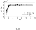
- FIGS. 3A through 3C show that idle long-time relaxation is classified by a battery abnormality diagnosis apparatus according to an embodiment of the present invention.
- FIG. 3A shows a voltage estimation equation for a voltage of a battery cell as a graph
- FIG. 3B shows a slope of the graph of FIG. 3A
- FIG. 3C shows a slope difference for the slope of FIG. 3B
- an x axis indicates time m
- a y axis of FIG. 3A indicates voltage V
- a y axis of FIG. 3B indicates a slope a of the voltage estimation equation
- a y axis of FIG. 3C indicates a slope difference diff(a).
- the battery abnormality diagnosis apparatus 200 may diagnose the battery cell as idle long-time relaxation abnormality when a standard deviation for the slope difference of the voltage estimation equation calculated as shown in FIG. 3A is less than the first reference value (6 ⁇ in FIG. 3 ). That is, referring to FIG. 3C , a part included in a graph region of 6 ⁇ (i.e., a bolded graph part) may indicate idle long-time relaxation abnormality of the battery cell.
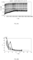
- FIGS. 4A through 4C show that post-charging idle voltage abnormality is classified by a battery abnormality diagnosis apparatus according to an embodiment of the present invention.
- FIGS. 4A through 4C an example of bank 1/rack 6/ module 13/cell 8 of an ESS battery is shown.
- FIG. 4A shows a voltage estimation equation for a voltage of a battery cell as a graph
- FIG. 4B shows a slope of the graph of FIG. 4A
- FIG. 4C shows a slope difference for the slope of FIG. 4B .
- an x axis indicates time m
- a y axis of FIG. 4A indicates voltage V
- a y axis of FIG. 4B indicates a slope a of a voltage estimation equation
- a y axis of FIG. 4C indicates a slope difference diff(a).
- the battery abnormality diagnosis apparatus 200 may diagnose the battery cell as post-charging or post-discharging idle voltage abnormality when the slope difference of the voltage estimation equation calculated as shown in FIG. 4A is greater than or equal to the first reference value (6 ⁇ in FIG. 4 ). That is, referring to FIG. 4C , a part out of the graph region of 6 ⁇ (i.e., a bolded graph part) may indicate post-charging or post-discharging idle voltage abnormality of the battery cell.
- the battery cell may be diagnosed as post-charging idle voltage abnormality when the start voltage of the idle period of the battery cell is greater than a second reference value (e.g., 3.8 V) and as post-discharging idle voltage abnormality when the start voltage of the idle period of the battery cell is less than or equal to the second reference value, in the case of the slope difference of the voltage estimation equation of FIG. 4C being greater than or equal to the first reference value.
- a second reference value e.g., 3.8 V
- the battery cell may be diagnosed as post-charging idle voltage abnormality when the current of the battery cell flows in the first direction (e.g., a (+) direction) and as post-discharging idle voltage abnormality when the current of the battery cell flows in the second direction (e.g., a (-) direction).
- first direction e.g., a (+) direction
- second direction e.g., a (-) direction
- FIG. 5 is a flowchart showing a battery abnormality diagnosis method according to an embodiment of the present invention.
- a battery abnormality diagnosis method measures a voltage X of a battery cell in operation S510.
- the voltage of the battery cell may be measured at specific time intervals.
- current flowing in the battery cell may also be measured.
- the voltage of the battery cell may be analyzed to calculate estimation information related to the voltage in an idle period (Ts - Te) of the battery cell, in operation S520.
- the estimation information may include a voltage estimation equation related to the voltage of the battery cell.
- the voltage estimation equation for the voltage of the battery cell may be calculated with respect to a set window size (e.g., 30 minutes).
- the voltage estimation equation of the battery cell may be Equation (1) described above.
- the slope difference diff(a) for the slope a may be calculated.
- the slope difference for the slope a may be expressed as at+1 - at.
- a time interval for the slope difference may be a sampling time (e.g., 1 second).
- the battery cell may be determined as idle long-time relaxation abnormality in operation S550.
- the slope difference e.g., an absolute value
- operation S560 it is determined whether a start voltage XTs of the idle period of the battery cell is greater than the preset second reference value (3.8 V in FIG. 5 ).
- the battery cell When the start voltage XTs of the idle period of the battery cell is less than or equal to the second reference value (No), the battery cell may be determined as post-discharging idle voltage abnormality in operation S570. Meanwhile, when the start voltage XTs of the idle period of the battery cell is greater than the second reference value (Yes), the battery cell may be determined as post-charging idle voltage abnormality in operation S580.
- the battery cell may be diagnosed as post-charging idle voltage abnormality when the current of the battery cell flows in the first direction (e.g., the (+) direction) and as post-discharging idle voltage abnormality when the current of the battery cell flows in the second direction (e.g., the (-) direction) that is opposite to the first direction.
- first direction e.g., the (+) direction
- second direction e.g., the (-) direction
- the abnormality type in the idle period of the battery may be classified.
- FIG. 6 is a block diagram showing a hardware structure of a battery abnormality diagnosis apparatus according to an embodiment of the present invention.
- a battery abnormality diagnosis apparatus 600 may include a microcontroller unit (MCU) 610, a memory 620, an input/output interface (I/F) 630, and a communication I/F 640.
- MCU microcontroller unit
- I/F input/output interface
- the MCU 610 may be a processor that executes various programs (e.g., a regression analysis program, a battery abnormality type classification program, etc.) stored in the memory 620, processes various data for regression analysis, abnormality type classification, etc., of the battery cell through these programs, and executes the above-described functions of FIG. 2 .
- programs e.g., a regression analysis program, a battery abnormality type classification program, etc.
- the memory 620 may store various programs regarding regression analysis, abnormality type classification, etc., of the battery cell. Moreover, the memory 620 may store various data such as measured voltage and current data of the battery cell, a graph corresponding to the voltage estimation equation, slope data, etc.
- the memory 620 may be provided in plural, depending on a need.
- the memory 620 may be a volatile or nonvolatile memory.
- RAM random access memory
- DRAM dynamic RAM
- SRAM static RAM
- ROM read only memory
- PROM programmable ROM
- EAROM electrically alterable ROM
- EPROM erasable PROM
- EEPROM electrically erasable PROM
- flash memory etc.
- the above-listed examples of the memory 620 are merely examples and are not limited thereto.
- the input/output I/F 630 may provide an interface for transmitting and receiving data by connecting an input device (not shown) such as a keyboard, a mouse, a touch panel, etc., and an output device such as a display (not shown), etc., with the MCU 610.
- an input device such as a keyboard, a mouse, a touch panel, etc.
- an output device such as a display (not shown), etc.
- the communication I/F 640 which is a component capable of transmitting and receiving various data to and from a server, may be various types of devices capable of supporting wired or wireless communication.
- a program for voltage estimation and abnormality type diagnosis of the battery cell or various data may be transmitted and received to and from a separately provided external server through the communication I/F 740.
- a computer program according to an embodiment of the present invention may be recorded in the memory 620 and processed by the MCU 610, thus being implemented as a module that performs function blocks shown in FIG. 2 .
Landscapes
- Physics & Mathematics (AREA)
- General Physics & Mathematics (AREA)
- Business, Economics & Management (AREA)
- Emergency Management (AREA)
- Secondary Cells (AREA)
- Charge And Discharge Circuits For Batteries Or The Like (AREA)
- Tests Of Electric Status Of Batteries (AREA)
- Testing Electric Properties And Detecting Electric Faults (AREA)
Abstract
Description
- This application claims priority to and the benefit of
Korean Patent Application No. 10-2020-0100131 filed in the Korean Intellectual Property Office on August 10, 2020 - The present invention relates to a battery abnormality diagnosis apparatus and method for diagnosing abnormality of a battery in an idle period.
- Recently, research and development of secondary batteries have been actively performed. Herein, the secondary batteries, which are chargeable/dischargeable batteries, may include all of conventional nickel (Ni)/cadmium (Cd) batteries, Ni/metal hydride (MH) batteries, etc., and recent lithium ion batteries. Among the secondary batteries, a lithium ion battery has a much higher energy density than those of the conventional Ni/Cd batteries, Ni/MH batteries, etc. Moreover, the lithium ion battery may be manufactured to be small and lightweight, such that the lithium ion battery has been used as a power source of mobile devices. In addition, the lithium ion battery is attracting attention as a next-generation energy storage medium as a usage range thereof is expanded to a power source of electric vehicles.
- Furthermore, the secondary battery is generally used as a battery pack including a battery module where a plurality of battery cells are connected to one another in series and/or in parallel. The battery pack may be managed and controlled by a battery management system in terms of a state and an operation.
- Meanwhile, generally, a secondary battery of an energy storage system (ESS) includes diagnosis lists for making a diagnosis before fire occurs. Such a diagnosis list includes several values regarding voltage, current, temperature, power, etc., for preventing the fire, and the secondary battery performs a diagnosis mainly for an over-voltage or an under-voltage.
- However, in the secondary battery, abnormality may substantially occur in a range other than a top or a base of a voltage. For example, fire may occur even when a warning notification for the over-voltage or the under-voltage is not generated. Thus, a new diagnosis item is required to solve the problems of fire as well as the over-voltage or the under-voltage.
- The present invention has been designed to solve the foregoing problems and aims to provide a battery abnormality diagnosis apparatus and method by which an abnormality type in an idle period of a battery may be classified by diagnosing an unstable behavior of a voltage in the idle period of the battery through regression analysis.
- A battery abnormality diagnosis apparatus according to an embodiment disclosed in this document includes a voltage obtaining unit obtaining a voltage of a battery cell, an analyzing unit calculating estimation information for estimating the voltage of the battery by analyzing the voltage of the battery cell, and a diagnosing unit diagnosing abnormality of the battery cell by analyzing the estimation information.
- In an embodiment, the estimation information may include a voltage estimation equation related to the voltage of the battery cell, and the diagnosing unit may diagnose the abnormality of the battery cell based on a slope difference with respect to time in the voltage estimation equation.
- In an embodiment, the diagnosing unit may diagnose the battery cell as idle long-time relaxation abnormality when the slope difference is less than a preset first reference value, and diagnose the battery cell as post-charging or post-discharging idle voltage abnormality when the slope difference is greater than or equal to the first reference value.
- In an embodiment, the first reference value may be determined based on a standard deviation for the slope difference of the voltage estimation equation for a plurality of battery cells included in a battery rack.
- In an embodiment, the diagnosing unit may diagnose the battery cell as post-charging idle voltage abnormality when a start voltage of an idle period of the battery cell is greater than a preset second reference value and diagnose the battery cell as post-discharging idle voltage abnormality when the start voltage of the idle period of the battery cell is less than or equal to the second reference value, in case of the slope difference being greater than or equal to the first reference value.
- In an embodiment, the second reference value may be determined as a voltage corresponding to a SOC of the battery cell being 50%.
- In an embodiment, the diagnosing unit may diagnose the battery cell as post-charging idle voltage abnormality when current of the battery cell flows in a first direction and diagnose the battery cell as post-discharging idle voltage abnormality when the current of the battery cell flows in a second direction that is opposite to the first direction, in case of the slope difference being greater than or equal to the first reference value.
- In an embodiment, the analyzing unit may calculate the voltage estimation equation in the idle period after charging or discharging of the battery cell.
- In an embodiment, the battery abnormality diagnosis apparatus may further include a notifying unit generating an alarming notification when the diagnosing unit determines that abnormality occurs in the battery cell.
- A battery abnormality diagnosis method according to an embodiment disclosed in this document includes obtaining a voltage of a battery cell, calculating estimation information for estimating the voltage of the battery by analyzing the voltage of the battery cell, and diagnosing abnormality of the battery cell by analyzing the estimation information.
- In an embodiment, the estimation information may include a voltage estimation equation related to the voltage of the battery cell, and the diagnosing of the abnormality of the battery cell may include diagnosing the abnormality of the battery cell based on a slope difference with respect to time in the voltage estimation equation.
- In an embodiment, the diagnosing of the abnormality of the battery cell may include diagnosing the battery cell as idle long-time relaxation abnormality when the slope difference is less than a first reference value, and diagnosing the battery cell as post-charging or post-discharging idle voltage abnormality when the slope difference is greater than or equal to the first reference value.
- In an embodiment, the diagnosing of the abnormality of the battery cell may include diagnosing the battery cell as post-charging idle voltage abnormality when a start voltage of an idle period of the battery cell is greater than a preset second reference value and diagnosing the battery cell as post-discharging idle voltage abnormality when the start voltage of the idle period of the battery cell is less than or equal to the second reference value, in case of the slope difference being greater than or equal to the first reference value.
- In an embodiment, the diagnosing of the abnormality of the battery cell may include diagnosing the battery cell as post-charging idle voltage abnormality when current of the battery cell flows in a first direction and diagnosing the battery cell as post-discharging idle voltage abnormality when the current of the battery cell flows in a second direction that is opposite to the first direction, in case of the slope difference being greater than or equal to the first reference value.
- According to the battery abnormality diagnosis apparatus and method of the present invention, by diagnosing an unstable behavior of a voltage in an idle period of a battery through regression analysis, an abnormality type in the idle period of the battery may be classified.
-
-
FIG. 1 is a block diagram of a general battery rack. -
FIG. 2 is a block diagram showing a structure of a battery abnormality diagnosis apparatus according to an embodiment of the present invention. -
FIGS. 3A through 3C show that idle long-time relaxation is classified by a battery abnormality diagnosis apparatus according to an embodiment of the present invention. -
FIGS. 4A through 4C show that post-charging idle voltage abnormality is classified by a battery abnormality diagnosis apparatus according to an embodiment of the present invention. -
FIG. 5 is a flowchart showing a battery abnormality diagnosis method according to an embodiment of the present invention. -
FIG. 6 is a block diagram showing a hardware structure of a battery abnormality diagnosis apparatus according to an embodiment of the present invention. - Hereinafter, various embodiments of the present invention will be described in detail with reference to the accompanying drawings. In this document, identical reference numerals will be used for identical components in the drawings, and the identical components will not be redundantly described.
- For various embodiments of the present invention disclosed in this document, specific structural or functional descriptions are only exemplified for the purpose of describing the embodiments of the present invention, and various embodiments of the present invention may be implemented in various forms, and should not be construed as being limited to the embodiments described in this document.
- As used in various embodiments, the terms "1st, "2nd", "first", "second", or the like may modify various components regardless of importance, and do not limit the components. For example, a first component may be named as a second component without departing from the right scope of the present disclosure, and similarly, the second component may be named as the first component.
- Terms used in the present document are used for only describing a specific exemplary embodiment of the disclosure and may not have an intention to limit the scope of other exemplary embodiments of the disclosure. It is to be understood that the singular forms include plural references unless the context clearly dictates otherwise.
- All of the terms used herein including technical or scientific terms have the same meanings as those generally understood by an ordinary skilled person in the related art. It will be further understood that terms, such as those defined in commonly used dictionaries, should be interpreted as having a meaning that is consistent with their meaning in the context of the relevant art and will not be interpreted in an idealized or overly formal sense unless expressly so defined herein. In some cases, the terms defined herein may be interpreted to exclude embodiments of the present disclosure.
-
FIG. 1 is a block diagram of a general battery rack. - Referring to
FIG. 1 , a battery control system including abattery rack 1 and a upper-level controller 2 included in a upper-level system according to an embodiment of the present invention is schematically shown. - As shown in
FIG. 1 , thebattery rack 1 may include abattery module 10 that includes one or more battery cells and is chargeable/dischargeable, aswitching unit 14 serially connected to a positive (+) terminal side or a negative (-) terminal side of thebattery module 10 to control a charging/discharging current flow of thebattery module 10, and a battery management system (e.g., RBMS) 20 for control and management to prevent over-charging and over-discharging by monitoring voltage, current, temperature, etc., of thebattery rack 1. Thebattery rack 1 may include a plurality ofbattery modules 10,sensors 12,switching units 14, andbattery management systems 20. - Herein, as the
switching unit 14 which is an element for controlling a current flow for charging or discharging of the plurality ofbattery modules 10, for example, at least one relay, magnetic contactor, etc., may be used according to specifications of thebattery rack 1. - The
battery management system 20, which is an interface for receiving measurement values of the above-described various parameters, may include a plurality of terminals and a circuit, etc., connected thereto to process input values. Thebattery management system 20 may control on/off of theswitching unit 14, e.g., a relay, a contactor, etc., and may be connected to thebattery module 10 to monitor a state of eachbattery module 10. - Meanwhile, the
battery management system 20 according to the present invention may perform regression analysis on a voltage of a battery cell through a separate program, as will be described below. An abnormal type of the battery cell may be classified using a calculated regression equation. - The upper-
level controller 2 may transmit a control signal regarding thebattery module 10 to thebattery management system 20. Thus, thebattery management system 20 may also be controlled in terms of an operation thereof based on a signal applied from the upper-level controller 2. Meanwhile, the battery cell according to the present invention may be included in thebattery module 10 used for an energy storage system (ESS). In this case, the upper-level controller 2 may be a controller (BBMS) of a battery bank including a plurality of racks or an ESS controller for controlling the entire ESS including a plurality of banks. However, thebattery rack 1 is not limited to such a purpose. - Such configurations of the
battery rack 1 and thebattery management system 20 are well-known configurations, and thus will not be described in detail. -
FIG. 2 is a block diagram showing a structure of a battery abnormality diagnosis apparatus according to an embodiment of the present invention. - A battery
abnormality diagnosis apparatus 200 ofFIG. 2 may be included in a BMS that manages thebattery module 10, a BMS that manages thebattery rack 1, or a system controller that manages the entire ESS, and may diagnose abnormality by collecting voltage data of each battery module from a plurality of rack BMSs included in a plurality of banks. For example, the batteryabnormality diagnosis apparatus 200 ofFIG. 2 may be included in thebattery management system 20 or the upper-level controller 2 ofFIG. 1 described above. - Classification, performed by the battery
abnormality diagnosis apparatus 200 according to an embodiment of the present invention, of the abnormality type of the battery cell may be a process after it is determined that abnormality occurs in the battery cell through an abnormality detection algorithm (e.g., main component analysis, etc.) of the battery cell. That is, the following description will be made of the batteryabnormality diagnosis apparatus 200 according to the present invention on the assumption that occurrence of an abnormal behavior in the battery cell has been already detected through a series of processes. However, this is merely an example, and the present invention is not limited thereto, and the batteryabnormality diagnosis apparatus 200 according to the present invention may class the abnormality type by analyzing data in real time regardless of determination of whether the abnormal behavior is detected. - Referring to
FIG. 2 , the batteryabnormality diagnosis apparatus 200 according to an embodiment of the present invention may include avoltage obtaining unit 210, an analyzingunit 220, a diagnosingunit 230, and a notifyingunit 240. - The
voltage obtaining unit 210 may obtain a voltage of the battery cell. For example, thevoltage obtaining unit 210 may measure the voltage of the battery cell at specific time intervals. According to an embodiment, thevoltage obtaining unit 210 may receive the measured voltage of the battery cell from another device. In addition, thevoltage obtaining unit 210 may measure current flowing in the battery cell. - The analyzing
unit 220 may calculate estimation information related to the voltage of the battery cell by analyzing the obtained voltage of the battery cell. According to an embodiment, the estimation information may include a voltage estimation equation related to the voltage of the battery cell. According to an embodiment, the analyzingunit 220 may calculate the voltage estimation equation of the battery cell by performing regression analysis on the obtained voltage of the battery cell. In this case, the analyzingunit 220 may calculate the voltage estimation equation for the idle period after charging or discharging of the battery cell. The analyzingunit 220 may calculate the voltage estimation equation regarding the voltage of the battery cell with respect to a set window size (e.g., 30 minutes). For example, the analyzingunit 220 may calculate the voltage estimation equation as below.
(where Ts indicates a start time of an idle period, Te indicates an end time of the idle period, and X indicates a voltage of a battery cell.) - The diagnosing
unit 230 may diagnose abnormality of the battery cell by analyzing the voltage estimation equation calculated by the analyzingunit 220. For example, the diagnosingunit 230 may calculate a slope a of the voltage estimation equation and a slope difference (at+1 - at), and use them to diagnose abnormality of the battery cell. A time interval regarding the slope difference may be a sampling time (e.g., 1 second). - More specifically, the diagnosing
unit 230 may diagnose the battery cell as idle long-time relaxation abnormality, when a standard deviation for the slope difference of the voltage estimation equation is less than a preset first reference value. In this case, the first reference value may be determined based on a multiple of a standard deviation σ for a slope difference of a voltage estimation equation for a plurality of battery cells included in a battery rack. For example, the first reference value may be 6o. - Herein, idle long-time relaxation of the battery cell may be an abnormal type where the battery cell takes a longer time to reach a stable state than other battery cells after the idle state. When such idle long-time relaxation occurs, it may mean that an operation between an anode and a cathode in the battery cell is not smooth, causing a problem in battery performance.
- In addition, the diagnosing
unit 230 may diagnose the battery cell as post-charging or post-discharging idle voltage abnormality when the slope difference of the voltage estimation equation is greater than or equal to the first reference value. The post-charging or post-discharging idle voltage abnormality of the battery cell indicates an abnormality type where the voltage is unstable rather than gently increasing or decreasing in a post-charging or post-discharging idle period of the battery cell. For example, in the case of post-charging or post-discharging idle voltage abnormality of the battery cell, the slope of the voltage of the battery cell may change out of a certain sigma level. - More specifically, the diagnosing
unit 230 may diagnose the battery cell as post-charging idle voltage abnormality when a start voltage of the idle period of the battery cell is greater than a preset second reference value, and diagnose the battery cell as post-discharging idle voltage abnormality when the start voltage of the idle period of the battery cell is less than or equal to the second reference value, in the case of the slope difference of the voltage estimation equation being greater than or equal to the first reference value. For example, the second reference value may be determined as a voltage corresponding to a SOC of the battery cell being 50%. - The diagnosing
unit 230 may diagnose the battery cell as post-charging idle voltage abnormality when current of the battery cell flows in a first direction and diagnose the battery cell as post-discharging idle voltage abnormality when the current of the battery cell flows in a second direction that is opposite to the first direction, in the case of the slope difference of the voltage estimation equation being greater than or equal to the first reference value. In this case, the direction of the current may be indicated by (+) or (-). - The notifying
unit 240 may generate an alarming notification when it is determined by the diagnosingunit 230 that abnormality occurs in the battery cell. In this case, the notifyingunit 240 may generate a different alarming notification for each of three battery abnormality types, i.e., idle long-time relaxation, post-charging idle voltage abnormality, and post-discharging idle voltage abnormality, to allow a user to identify each abnormality type. For example, the notifyingunit 240 may include a lamp, a speaker, etc. - Meanwhile, although not shown in
FIG. 2 , the batteryabnormality diagnosis apparatus 200 according to an embodiment of the present invention may include a storing unit. In this case, the storing unit may store various data such as voltage and current data obtained by thevoltage obtaining unit 210, a voltage estimation equation and a graph calculated by the analyzingunit 220, a standard deviation for a slope difference of a voltage estimation equation, etc. The batteryabnormality diagnosis apparatus 200 according to an embodiment of the present invention may operate by transmitting and receiving the above-described data in communication with an external server through a communicating unit (not shown) instead of including the storing unit. - Moreover, although it is illustrated in
FIG. 2 that the batteryabnormality diagnosis apparatus 200 according to an embodiment of the present invention classifies the battery cell into the types of idle long-time relaxation, post-charging idle voltage abnormality, and post-discharging idle voltage abnormality, the present invention is not limited thereto, and classification into various abnormality types may be possible through a statistical method. - A method for classifying the battery cell as an abnormality type may also make a diagnosis in other various statistical methods without being limited to the above-described method. For example, the slope of the voltage estimation equation may be used in place of the slope difference of the voltage estimation equation, and other data such as differential data, etc., may be used.
- As such, with the battery
abnormality diagnosis apparatus 200 according to an embodiment of the present invention, by diagnosing the unstable behavior of the voltage in the idle period of the battery, the abnormality type in the idle period of the battery may be classified. -
FIGS. 3A through 3C show that idle long-time relaxation is classified by a battery abnormality diagnosis apparatus according to an embodiment of the present invention. - Referring to
FIGS. 3A through 3C , an example ofbank 1/rack 6/ module 13/cell 8 of an ESS battery is shown. More specifically,FIG. 3A shows a voltage estimation equation for a voltage of a battery cell as a graph,FIG. 3B shows a slope of the graph ofFIG. 3A , andFIG. 3C shows a slope difference for the slope ofFIG. 3B . In each graph ofFIG. 3 , an x axis indicates time m, a y axis ofFIG. 3A indicates voltage V, a y axis ofFIG. 3B indicates a slope a of the voltage estimation equation, and a y axis ofFIG. 3C indicates a slope difference diff(a). - As shown in
FIG. 3C , the batteryabnormality diagnosis apparatus 200 according to an embodiment of the present invention may diagnose the battery cell as idle long-time relaxation abnormality when a standard deviation for the slope difference of the voltage estimation equation calculated as shown inFIG. 3A is less than the first reference value (6σ inFIG. 3 ). That is, referring toFIG. 3C , a part included in a graph region of 6σ (i.e., a bolded graph part) may indicate idle long-time relaxation abnormality of the battery cell. -
FIGS. 4A through 4C show that post-charging idle voltage abnormality is classified by a battery abnormality diagnosis apparatus according to an embodiment of the present invention. - Referring to
FIGS. 4A through 4C , an example ofbank 1/rack 6/ module 13/cell 8 of an ESS battery is shown. LikeFIG. 3 ,FIG. 4A shows a voltage estimation equation for a voltage of a battery cell as a graph,FIG. 4B shows a slope of the graph ofFIG. 4A , andFIG. 4C shows a slope difference for the slope ofFIG. 4B . In each graph ofFIG. 4 , an x axis indicates time m, a y axis ofFIG. 4A indicates voltage V, a y axis ofFIG. 4B indicates a slope a of a voltage estimation equation, and a y axis ofFIG. 4C indicates a slope difference diff(a). - As shown in
FIG. 4C , the batteryabnormality diagnosis apparatus 200 according to an embodiment of the present invention may diagnose the battery cell as post-charging or post-discharging idle voltage abnormality when the slope difference of the voltage estimation equation calculated as shown inFIG. 4A is greater than or equal to the first reference value (6σ inFIG. 4 ). That is, referring toFIG. 4C , a part out of the graph region of 6σ (i.e., a bolded graph part) may indicate post-charging or post-discharging idle voltage abnormality of the battery cell. - More specifically, the battery cell may be diagnosed as post-charging idle voltage abnormality when the start voltage of the idle period of the battery cell is greater than a second reference value (e.g., 3.8 V) and as post-discharging idle voltage abnormality when the start voltage of the idle period of the battery cell is less than or equal to the second reference value, in the case of the slope difference of the voltage estimation equation of
FIG. 4C being greater than or equal to the first reference value. - Meanwhile, in the case of the slope difference of the voltage estimation equation of
FIG. 4C being greater than or equal to the first reference value, the battery cell may be diagnosed as post-charging idle voltage abnormality when the current of the battery cell flows in the first direction (e.g., a (+) direction) and as post-discharging idle voltage abnormality when the current of the battery cell flows in the second direction (e.g., a (-) direction). -
FIG. 5 is a flowchart showing a battery abnormality diagnosis method according to an embodiment of the present invention. - Referring to
FIG. 5 , a battery abnormality diagnosis method according to an embodiment of the present invention measures a voltage X of a battery cell in operation S510. In this case, in operation S510, the voltage of the battery cell may be measured at specific time intervals. In addition, current flowing in the battery cell may also be measured. - The voltage of the battery cell may be analyzed to calculate estimation information related to the voltage in an idle period (Ts - Te) of the battery cell, in operation S520. For example, the estimation information may include a voltage estimation equation related to the voltage of the battery cell. The voltage estimation equation for the voltage of the battery cell may be calculated with respect to a set window size (e.g., 30 minutes). For example, the voltage estimation equation of the battery cell may be Equation (1) described above.
- In operation S530, the slope difference diff(a) for the slope a may be calculated. In this case, the slope difference for the slope a may be expressed as at+1 - at. A time interval for the slope difference may be a sampling time (e.g., 1 second).
- Next, it is determined whether the slope difference (e.g., an absolute value) of the voltage estimation equation is greater than or equal to the preset first reference value (6σ in
FIG. 5 ) in operation S540. When the slope difference of the voltage estimation equation is less than the first reference value (No), the battery cell may be determined as idle long-time relaxation abnormality in operation S550. - Meanwhile, when the slope difference of the voltage estimation equation is greater than or equal to the first reference value (Yes), the process goes to operation S560. In operation S560, it is determined whether a start voltage XTs of the idle period of the battery cell is greater than the preset second reference value (3.8 V in
FIG. 5 ). - When the start voltage XTs of the idle period of the battery cell is less than or equal to the second reference value (No), the battery cell may be determined as post-discharging idle voltage abnormality in operation S570. Meanwhile, when the start voltage XTs of the idle period of the battery cell is greater than the second reference value (Yes), the battery cell may be determined as post-charging idle voltage abnormality in operation S580.
- Meanwhile, instead of the method of operations S560 through S580, the battery cell may be diagnosed as post-charging idle voltage abnormality when the current of the battery cell flows in the first direction (e.g., the (+) direction) and as post-discharging idle voltage abnormality when the current of the battery cell flows in the second direction (e.g., the (-) direction) that is opposite to the first direction.
- As such, with the battery abnormality diagnosis method according to an embodiment of the present invention, by analyzing the unstable behavior of the voltage in the idle period of the battery, the abnormality type in the idle period of the battery may be classified.
-
FIG. 6 is a block diagram showing a hardware structure of a battery abnormality diagnosis apparatus according to an embodiment of the present invention. - Referring to
FIG. 6 , a batteryabnormality diagnosis apparatus 600 according to an embodiment of the present invention may include a microcontroller unit (MCU) 610, amemory 620, an input/output interface (I/F) 630, and a communication I/F 640. - The
MCU 610 may be a processor that executes various programs (e.g., a regression analysis program, a battery abnormality type classification program, etc.) stored in thememory 620, processes various data for regression analysis, abnormality type classification, etc., of the battery cell through these programs, and executes the above-described functions ofFIG. 2 . - The
memory 620 may store various programs regarding regression analysis, abnormality type classification, etc., of the battery cell. Moreover, thememory 620 may store various data such as measured voltage and current data of the battery cell, a graph corresponding to the voltage estimation equation, slope data, etc. - The
memory 620 may be provided in plural, depending on a need. Thememory 620 may be a volatile or nonvolatile memory. For thememory 620 as the volatile memory, random access memory (RAM), dynamic RAM (DRAM), static RAM (SRAM), etc., may be used. For thememory 620 as the nonvolatile memory, read only memory (ROM), programmable ROM (PROM), electrically alterable ROM (EAROM), erasable PROM (EPROM), electrically erasable PROM (EEPROM), flash memory, etc., may be used. The above-listed examples of thememory 620 are merely examples and are not limited thereto. - The input/output I/
F 630 may provide an interface for transmitting and receiving data by connecting an input device (not shown) such as a keyboard, a mouse, a touch panel, etc., and an output device such as a display (not shown), etc., with theMCU 610. - The communication I/
F 640, which is a component capable of transmitting and receiving various data to and from a server, may be various types of devices capable of supporting wired or wireless communication. For example, a program for voltage estimation and abnormality type diagnosis of the battery cell or various data may be transmitted and received to and from a separately provided external server through the communication I/F 740. - As such, a computer program according to an embodiment of the present invention may be recorded in the
memory 620 and processed by theMCU 610, thus being implemented as a module that performs function blocks shown inFIG. 2 . - Even though all components constituting an embodiment of the present invention have been described above as being combined into one or operating in combination, the present invention is not necessarily limited to the embodiment. That is, within the object scope of the present invention, all the components may operate by being selectively combined into one or more.
- Moreover, terms such as "include", "constitute" or "have" described above may mean that the corresponding component may be inherent unless otherwise stated, and thus should be construed as further including other components rather than excluding other components. All terms including technical or scientific terms have the same meanings as those generally understood by those of ordinary skill in the art unless defined otherwise. The terms used generally like terms defined in dictionaries should be interpreted as having meanings that are the same as the contextual meanings of the relevant technology and should not be interpreted as having ideal or excessively formal meanings unless they are clearly defined in the present invention.
- The above description is merely illustrative of the technical idea of the present invention, and various modifications and variations will be possible without departing from the essential characteristics of the present invention by those of ordinary skill in the art to which the present invention pertains Therefore, the embodiments disclosed in the present invention are intended for description rather than limitation of the technical spirit of the present invention, and the scope of the technical spirit of the present invention is not limited by these embodiments. The protection scope of the present invention should be interpreted by the following claims, and all technical spirits within the same range should be understood to be included in the range of the present invention.
Claims (14)
- A battery abnormality diagnosis apparatus comprising:a voltage obtaining unit configured to obtain a voltage of a battery cell;an analyzing unit configured to calculate estimation information for estimating the voltage of the battery by analyzing the voltage of the battery cell; anda diagnosing unit configured to diagnose an abnormality of the battery cell by analyzing the estimation information.
- The battery abnormality diagnosis apparatus of claim 1, wherein the estimation information comprises a voltage estimation equation related to the voltage of the battery cell, and
wherein the diagnosing unit is configured to diagnose the abnormality of the battery cell based on a slope difference with respect to time in the voltage estimation equation. - The battery abnormality diagnosis apparatus of claim 2, wherein the diagnosing unit is configured to diagnose the battery cell as idle long-time relaxation abnormality when the slope difference is less than a preset first reference value, and diagnose the battery cell as post-charging or post-discharging idle voltage abnormality when the slope difference is greater than or equal to the first reference value.
- The battery abnormality diagnosis apparatus of claim 3, wherein the first reference value is determined based on a standard deviation for the slope difference of the voltage estimation equation for a plurality of battery cells included in a battery rack.
- The battery abnormality diagnosis apparatus of claim 3, wherein the diagnosing unit is configured to diagnose the battery cell as post-charging idle voltage abnormality when a start voltage of an idle period of the battery cell is greater than a preset second reference value and diagnoses the battery cell as post-discharging idle voltage abnormality when the start voltage of the idle period of the battery cell is less than or equal to the second reference value, in case of the slope difference being greater than or equal to the first reference value.
- The battery abnormality diagnosis apparatus of claim 5, wherein the second reference value is determined as a voltage corresponding to an SOC of the battery cell being 50%.
- The battery abnormality diagnosis apparatus of claim 3, wherein the diagnosing unit diagnoses the battery cell as post-charging idle voltage abnormality when current of the battery cell flows in a first direction and diagnoses the battery cell as post-discharging idle voltage abnormality when the current of the battery cell flows in a second direction that is opposite to the first direction, in case of the slope difference being greater than or equal to the first reference value.
- The battery abnormality diagnosis apparatus of claim 2, wherein the analyzing unit is configured to calculate the voltage estimation equation in an idle period after charging or discharging of the battery cell.
- The battery abnormality diagnosis apparatus of claim 1, further comprising a notifying unit configured to generate an alarming notification when the diagnosing unit determines that the abnormality occurs in the battery cell.
- A battery abnormality diagnosis method comprising:obtaining a voltage of a battery cell;calculating estimation information for estimating the voltage of the battery by analyzing the voltage of the battery cell; anddiagnosing abnormality of the battery cell by analyzing the estimation information.
- The battery abnormality diagnosis method of claim 10, wherein the estimation information comprises a voltage estimation equation related to the voltage of the battery cell, and
wherein the diagnosing of the abnormality of the battery cell comprises diagnosing the abnormality of the battery cell based on a slope difference with respect to time in the voltage estimation equation. - The battery abnormality diagnosis method of claim 11, wherein the diagnosing of the abnormality of the battery cell comprises:diagnosing the battery cell as idle long-time relaxation abnormality when the slope difference is less than a first reference value; anddiagnosing the battery cell as post-charging or post-discharging idle voltage abnormality when the slope difference is greater than or equal to the first reference value.
- The battery abnormality diagnosis method of claim 12, wherein the diagnosing of the abnormality of the battery cell comprises diagnosing the battery cell as post-charging idle voltage abnormality when a start voltage of an idle period of the battery cell is greater than a preset second reference value and diagnosing the battery cell as post-discharging idle voltage abnormality when the start voltage of the idle period of the battery cell is less than or equal to the second reference value, in case of the slope difference being greater than or equal to the first reference value.
- The battery abnormality diagnosis method of claim 12, wherein the diagnosing of the abnormality of the battery cell comprises diagnosing the battery cell as post-charging idle voltage abnormality when current of the battery cell flows in a first direction and diagnosing the battery cell as post-discharging idle voltage abnormality when the current of the battery cell flows in a second direction that is opposite to the first direction, in case of the slope difference being greater than or equal to the first reference value.
Applications Claiming Priority (2)
| Application Number | Priority Date | Filing Date | Title |
|---|---|---|---|
| KR20200100131 | 2020-08-10 | ||
| PCT/KR2021/010470 WO2022035149A1 (en) | 2020-08-10 | 2021-08-09 | Device and method for diagnosing battery abnormality |
Publications (3)
| Publication Number | Publication Date |
|---|---|
| EP4155744A1 true EP4155744A1 (en) | 2023-03-29 |
| EP4155744A4 EP4155744A4 (en) | 2023-11-29 |
| EP4155744B1 EP4155744B1 (en) | 2025-10-01 |
Family
ID=80246801
Family Applications (1)
| Application Number | Title | Priority Date | Filing Date |
|---|---|---|---|
| EP21856155.3A Active EP4155744B1 (en) | 2020-08-10 | 2021-08-09 | Battery abnormality diagnosis apparatus and method |
Country Status (8)
| Country | Link |
|---|---|
| US (1) | US12566214B2 (en) |
| EP (1) | EP4155744B1 (en) |
| JP (1) | JP7546702B2 (en) |
| KR (1) | KR102927153B1 (en) |
| CN (1) | CN115867815A (en) |
| ES (1) | ES3051518T3 (en) |
| HU (1) | HUE073124T2 (en) |
| WO (1) | WO2022035149A1 (en) |
Families Citing this family (11)
| Publication number | Priority date | Publication date | Assignee | Title |
|---|---|---|---|---|
| KR102900854B1 (en) * | 2022-09-16 | 2025-12-16 | 주식회사 엘지에너지솔루션 | Battery diagnosis apparatus, battery diagnosis method, battery pack, and vehicle including the same |
| KR102890378B1 (en) * | 2022-09-16 | 2025-11-24 | 주식회사 엘지에너지솔루션 | Battery diagnosis apparatus, battery diagnosis method, battery pack, and vehicle including the same |
| KR20240040991A (en) * | 2022-09-22 | 2024-03-29 | 주식회사 엘지에너지솔루션 | Apparatus and method for analysing test of battery's long time characteristics |
| KR102698009B1 (en) * | 2022-10-26 | 2024-08-21 | 주식회사 엘지에너지솔루션 | Apparatus and method for diagnosing battery |
| KR20240069507A (en) * | 2022-11-11 | 2024-05-20 | 주식회사 엘지에너지솔루션 | Apparatus for diagnosing battery and operating method thereof |
| KR20250052818A (en) * | 2023-10-12 | 2025-04-21 | 주식회사 엘지에너지솔루션 | Apparatus for managing battery and operating method of the same |
| KR20250083922A (en) * | 2023-12-01 | 2025-06-10 | 주식회사 엘지에너지솔루션 | Apparatus for managing battery and operating method of the same |
| CN120233244A (en) | 2023-12-29 | 2025-07-01 | 台达电子工业股份有限公司 | Fault detection method and fault detection system applied to battery cabinet |
| KR20250116366A (en) * | 2024-01-25 | 2025-08-01 | 주식회사 엘지에너지솔루션 | Battery diagnosis apparatus and battery diagnosis method |
| KR20250152865A (en) * | 2024-04-17 | 2025-10-24 | 주식회사 엘지에너지솔루션 | Battery diagnosing apparatus and operating method thereof |
| WO2026089402A1 (en) * | 2024-10-25 | 2026-04-30 | 주식회사 엘지에너지솔루션 | Battery diagnosis apparatus and battery diagnosis method |
Family Cites Families (31)
| Publication number | Priority date | Publication date | Assignee | Title |
|---|---|---|---|---|
| JP3540437B2 (en) | 1995-06-05 | 2004-07-07 | 本田技研工業株式会社 | Battery status determination device |
| JP2002252901A (en) | 2001-02-23 | 2002-09-06 | Yazaki Corp | Method and device for detecting voltage-current characteristics of vehicle-mounted battery, method and device for calculating internal resistance of vehicle-mounted battery, method of detecting degree of deterioration of vehicle-mounted battery and device therefor |
| JP4019815B2 (en) * | 2002-06-26 | 2007-12-12 | 日産自動車株式会社 | Abnormality diagnosis apparatus and method for assembled battery |
| JP4186811B2 (en) | 2003-12-10 | 2008-11-26 | 松下電器産業株式会社 | Gas shut-off device |
| JP4638195B2 (en) | 2004-09-28 | 2011-02-23 | 富士重工業株式会社 | Battery degradation degree estimation device |
| US7688033B2 (en) | 2004-09-29 | 2010-03-30 | Panasonic Ev Energy Co., Ltd. | Method for detecting state of secondary battery and device for detecting state of secondary battery |
| JP4668015B2 (en) | 2004-09-29 | 2011-04-13 | プライムアースEvエナジー株式会社 | Secondary battery state detection method and secondary battery state detection device |
| JP2008256436A (en) | 2007-04-03 | 2008-10-23 | Yazaki Corp | Approximate expression calculating apparatus and method, and battery state monitoring apparatus |
| JP2009250796A (en) | 2008-04-07 | 2009-10-29 | Mitsubishi Electric Corp | Method of diagnosing deterioration of storage battery and diagnostic system |
| US8219333B2 (en) * | 2010-06-29 | 2012-07-10 | O2Micro, Inc | Battery management systems for protecting batteries from fault conditions |
| JP5786324B2 (en) | 2010-11-17 | 2015-09-30 | 日産自動車株式会社 | Battery control device |
| JP5994240B2 (en) | 2011-12-02 | 2016-09-21 | 日産自動車株式会社 | Battery control device |
| JP5596083B2 (en) | 2012-06-26 | 2014-09-24 | Imv株式会社 | Lithium-ion secondary battery deterioration diagnosis device |
| JP5938633B2 (en) | 2012-09-28 | 2016-06-22 | 三菱自動車工業株式会社 | Battery chargeability determination device |
| KR101642329B1 (en) | 2013-09-30 | 2016-07-25 | 주식회사 엘지화학 | Battery management apparatus and Method for managing the battery using the same |
| JP6532374B2 (en) | 2015-10-16 | 2019-06-19 | 株式会社Nttファシリティーズ | Storage battery state analysis system, storage battery state analysis method, and storage battery state analysis program |
| JP6532373B2 (en) | 2015-10-16 | 2019-06-19 | 株式会社Nttファシリティーズ | Storage battery deterioration estimation system, storage battery deterioration estimation method and storage battery deterioration estimation program |
| EP3410136B1 (en) * | 2016-01-28 | 2022-02-02 | Panasonic Intellectual Property Management Co., Ltd. | Management device and power storage system |
| US9840161B2 (en) * | 2016-03-10 | 2017-12-12 | Ford Global Technologies, Llc | Circuit and method for detection of battery cell degradation events |
| JP6528906B2 (en) * | 2016-06-22 | 2019-06-12 | 株式会社豊田自動織機 | Power storage device and control method of power storage device |
| JP6589222B2 (en) | 2016-07-20 | 2019-10-16 | 公益財団法人鉄道総合技術研究所 | Voltage estimation device, voltage estimation method and program |
| US10641833B2 (en) * | 2016-11-18 | 2020-05-05 | Pacesetter, Inc. | Method of screening high rate electrochemical cells |
| KR102564005B1 (en) * | 2016-12-09 | 2023-08-07 | 현대자동차주식회사 | Apparatus and method for diagnosing deterioration of battery in eco-vehicle |
| US11226374B2 (en) * | 2017-10-17 | 2022-01-18 | The Board Of Trustees Of The Leland Stanford Junior University | Data-driven model for lithium-ion battery capacity fade and lifetime prediction |
| KR101930647B1 (en) | 2017-11-22 | 2019-03-11 | 주식회사 포스코아이씨티 | Apparatus and Method for Estimating Capacity of Battery Using Second Order Differential Voltage Curve |
| US20200355749A1 (en) | 2018-01-11 | 2020-11-12 | Semiconductor Energy Laboratory Co., Ltd. | Device detecting abnormality of secondary battery, abnormality detection method, and program |
| JP7044044B2 (en) | 2018-12-07 | 2022-03-30 | トヨタ自動車株式会社 | Deterioration degree estimation device for secondary batteries and deterioration degree estimation method for secondary batteries |
| CN110346726A (en) | 2019-05-28 | 2019-10-18 | 安徽沃博源科技有限公司 | Battery failures diagnostic method, device and electric car |
| CN111257764B (en) * | 2020-02-24 | 2025-09-30 | 武汉蔚来能源有限公司 | Method, system and device for monitoring battery short circuit |
| KR102717609B1 (en) | 2020-07-23 | 2024-10-16 | 주식회사 엘지에너지솔루션 | Apparatus and method for diagnosing battery |
| KR102782615B1 (en) | 2020-07-31 | 2025-03-18 | 주식회사 엘지에너지솔루션 | Battery diagnosis apparatus and method |
-
2021
- 2021-08-09 EP EP21856155.3A patent/EP4155744B1/en active Active
- 2021-08-09 CN CN202180046361.8A patent/CN115867815A/en active Pending
- 2021-08-09 ES ES21856155T patent/ES3051518T3/en active Active
- 2021-08-09 JP JP2022576515A patent/JP7546702B2/en active Active
- 2021-08-09 WO PCT/KR2021/010470 patent/WO2022035149A1/en not_active Ceased
- 2021-08-09 KR KR1020210104448A patent/KR102927153B1/en active Active
- 2021-08-09 US US18/014,297 patent/US12566214B2/en active Active
- 2021-08-09 HU HUE21856155A patent/HUE073124T2/en unknown
Also Published As
| Publication number | Publication date |
|---|---|
| US12566214B2 (en) | 2026-03-03 |
| KR102927153B1 (en) | 2026-02-12 |
| JP7546702B2 (en) | 2024-09-06 |
| ES3051518T3 (en) | 2025-12-29 |
| WO2022035149A1 (en) | 2022-02-17 |
| EP4155744B1 (en) | 2025-10-01 |
| JP2023529734A (en) | 2023-07-11 |
| EP4155744A4 (en) | 2023-11-29 |
| CN115867815A (en) | 2023-03-28 |
| HUE073124T2 (en) | 2026-01-28 |
| KR20220019637A (en) | 2022-02-17 |
| US20230258725A1 (en) | 2023-08-17 |
Similar Documents
| Publication | Publication Date | Title |
|---|---|---|
| EP4155744B1 (en) | Battery abnormality diagnosis apparatus and method | |
| US12130338B2 (en) | Battery abnormality diagnosis apparatus and method | |
| EP3958006B1 (en) | Battery diagnosis apparatus and method | |
| US20240003980A1 (en) | Battery management apparatus and method | |
| EP4170367A1 (en) | Battery capacity estimation device and method | |
| US12332320B2 (en) | Battery management apparatus and method | |
| EP4102239A1 (en) | Battery management device and method | |
| EP4446760B1 (en) | Battery depth-of-charge calculation apparatus and operating method thereof | |
| EP4206712A1 (en) | Apparatus and method for diagnosing battery | |
| EP4446764A1 (en) | Battery state management device and operation method thereof | |
| JP2022548918A (en) | Battery diagnostic device and method | |
| EP4692824A1 (en) | Battery management apparatus and operation method therefor | |
| EP4614167A1 (en) | Battery management device, and operation method thereof | |
| EP4513209A1 (en) | Battery management device and operation method therefor | |
| EP4600678A1 (en) | Battery management device and operation method therefor | |
| EP4682564A1 (en) | Battery management device and battery management method | |
| CN116324446B (en) | Battery management device and method |
Legal Events
| Date | Code | Title | Description |
|---|---|---|---|
| STAA | Information on the status of an ep patent application or granted ep patent |
Free format text: STATUS: THE INTERNATIONAL PUBLICATION HAS BEEN MADE |
|
| PUAI | Public reference made under article 153(3) epc to a published international application that has entered the european phase |
Free format text: ORIGINAL CODE: 0009012 |
|
| STAA | Information on the status of an ep patent application or granted ep patent |
Free format text: STATUS: REQUEST FOR EXAMINATION WAS MADE |
|
| 17P | Request for examination filed |
Effective date: 20221222 |
|
| AK | Designated contracting states |
Kind code of ref document: A1 Designated state(s): AL AT BE BG CH CY CZ DE DK EE ES FI FR GB GR HR HU IE IS IT LI LT LU LV MC MK MT NL NO PL PT RO RS SE SI SK SM TR |
|
| DAV | Request for validation of the european patent (deleted) | ||
| DAX | Request for extension of the european patent (deleted) | ||
| A4 | Supplementary search report drawn up and despatched |
Effective date: 20231026 |
|
| RIC1 | Information provided on ipc code assigned before grant |
Ipc: G08B 21/18 20060101ALI20231020BHEP Ipc: G01R 31/392 20190101ALI20231020BHEP Ipc: G01R 31/396 20190101ALI20231020BHEP Ipc: G01R 31/382 20190101ALI20231020BHEP Ipc: G01R 31/36 20200101ALI20231020BHEP Ipc: G01R 31/367 20190101AFI20231020BHEP |
|
| STAA | Information on the status of an ep patent application or granted ep patent |
Free format text: STATUS: EXAMINATION IS IN PROGRESS |
|
| 17Q | First examination report despatched |
Effective date: 20250227 |
|
| GRAP | Despatch of communication of intention to grant a patent |
Free format text: ORIGINAL CODE: EPIDOSNIGR1 |
|
| STAA | Information on the status of an ep patent application or granted ep patent |
Free format text: STATUS: GRANT OF PATENT IS INTENDED |
|
| INTG | Intention to grant announced |
Effective date: 20250528 |
|
| GRAS | Grant fee paid |
Free format text: ORIGINAL CODE: EPIDOSNIGR3 |
|
| GRAA | (expected) grant |
Free format text: ORIGINAL CODE: 0009210 |
|
| STAA | Information on the status of an ep patent application or granted ep patent |
Free format text: STATUS: THE PATENT HAS BEEN GRANTED |
|
| P01 | Opt-out of the competence of the unified patent court (upc) registered |
Free format text: CASE NUMBER: UPC_APP_2748_4155744/2025 Effective date: 20250807 |
|
| AK | Designated contracting states |
Kind code of ref document: B1 Designated state(s): AL AT BE BG CH CY CZ DE DK EE ES FI FR GB GR HR HU IE IS IT LI LT LU LV MC MK MT NL NO PL PT RO RS SE SI SK SM TR |
|
| REG | Reference to a national code |
Ref country code: GB Ref legal event code: FG4D Ref country code: CH Ref legal event code: F10 Free format text: ST27 STATUS EVENT CODE: U-0-0-F10-F00 (AS PROVIDED BY THE NATIONAL OFFICE) Effective date: 20251001 |
|
| REG | Reference to a national code |
Ref country code: IE Ref legal event code: FG4D |
|
| REG | Reference to a national code |
Ref country code: DE Ref legal event code: R096 Ref document number: 602021039757 Country of ref document: DE |
|
| REG | Reference to a national code |
Ref country code: ES Ref legal event code: FG2A Ref document number: 3051518 Country of ref document: ES Kind code of ref document: T3 Effective date: 20251229 |
|
| REG | Reference to a national code |
Ref country code: HU Ref legal event code: AG4A Ref document number: E073124 Country of ref document: HU |
|
| REG | Reference to a national code |
Ref country code: NL Ref legal event code: MP Effective date: 20251001 |
|
| REG | Reference to a national code |
Ref country code: AT Ref legal event code: MK05 Ref document number: 1842978 Country of ref document: AT Kind code of ref document: T Effective date: 20251001 |
|
| PG25 | Lapsed in a contracting state [announced via postgrant information from national office to epo] |
Ref country code: NL Free format text: LAPSE BECAUSE OF FAILURE TO SUBMIT A TRANSLATION OF THE DESCRIPTION OR TO PAY THE FEE WITHIN THE PRESCRIBED TIME-LIMIT Effective date: 20251001 |
|
| REG | Reference to a national code |
Ref country code: LT Ref legal event code: MG9D |
|
| PG25 | Lapsed in a contracting state [announced via postgrant information from national office to epo] |
Ref country code: NO Free format text: LAPSE BECAUSE OF FAILURE TO SUBMIT A TRANSLATION OF THE DESCRIPTION OR TO PAY THE FEE WITHIN THE PRESCRIBED TIME-LIMIT Effective date: 20260101 |
|
| PG25 | Lapsed in a contracting state [announced via postgrant information from national office to epo] |
Ref country code: HR Free format text: LAPSE BECAUSE OF FAILURE TO SUBMIT A TRANSLATION OF THE DESCRIPTION OR TO PAY THE FEE WITHIN THE PRESCRIBED TIME-LIMIT Effective date: 20251001 Ref country code: AT Free format text: LAPSE BECAUSE OF FAILURE TO SUBMIT A TRANSLATION OF THE DESCRIPTION OR TO PAY THE FEE WITHIN THE PRESCRIBED TIME-LIMIT Effective date: 20251001 Ref country code: FI Free format text: LAPSE BECAUSE OF FAILURE TO SUBMIT A TRANSLATION OF THE DESCRIPTION OR TO PAY THE FEE WITHIN THE PRESCRIBED TIME-LIMIT Effective date: 20251001 |
|
| PG25 | Lapsed in a contracting state [announced via postgrant information from national office to epo] |
Ref country code: RS Free format text: LAPSE BECAUSE OF FAILURE TO SUBMIT A TRANSLATION OF THE DESCRIPTION OR TO PAY THE FEE WITHIN THE PRESCRIBED TIME-LIMIT Effective date: 20260101 |
|
| PG25 | Lapsed in a contracting state [announced via postgrant information from national office to epo] |
Ref country code: IS Free format text: LAPSE BECAUSE OF FAILURE TO SUBMIT A TRANSLATION OF THE DESCRIPTION OR TO PAY THE FEE WITHIN THE PRESCRIBED TIME-LIMIT Effective date: 20260201 |
|
| PG25 | Lapsed in a contracting state [announced via postgrant information from national office to epo] |
Ref country code: PT Free format text: LAPSE BECAUSE OF FAILURE TO SUBMIT A TRANSLATION OF THE DESCRIPTION OR TO PAY THE FEE WITHIN THE PRESCRIBED TIME-LIMIT Effective date: 20260202 Ref country code: CZ Free format text: LAPSE BECAUSE OF FAILURE TO SUBMIT A TRANSLATION OF THE DESCRIPTION OR TO PAY THE FEE WITHIN THE PRESCRIBED TIME-LIMIT Effective date: 20251001 |
|
| PG25 | Lapsed in a contracting state [announced via postgrant information from national office to epo] |
Ref country code: PL Free format text: LAPSE BECAUSE OF FAILURE TO SUBMIT A TRANSLATION OF THE DESCRIPTION OR TO PAY THE FEE WITHIN THE PRESCRIBED TIME-LIMIT Effective date: 20251001 |
|
| PG25 | Lapsed in a contracting state [announced via postgrant information from national office to epo] |
Ref country code: LV Free format text: LAPSE BECAUSE OF FAILURE TO SUBMIT A TRANSLATION OF THE DESCRIPTION OR TO PAY THE FEE WITHIN THE PRESCRIBED TIME-LIMIT Effective date: 20251001 |
|
| PG25 | Lapsed in a contracting state [announced via postgrant information from national office to epo] |
Ref country code: BG Free format text: LAPSE BECAUSE OF FAILURE TO SUBMIT A TRANSLATION OF THE DESCRIPTION OR TO PAY THE FEE WITHIN THE PRESCRIBED TIME-LIMIT Effective date: 20251001 |