EP4155612A1 - Pre-combustion chamber for feeding a turbine in a liquid propellant rocket engine - Google Patents
Pre-combustion chamber for feeding a turbine in a liquid propellant rocket engine Download PDFInfo
- Publication number
- EP4155612A1 EP4155612A1 EP22020455.6A EP22020455A EP4155612A1 EP 4155612 A1 EP4155612 A1 EP 4155612A1 EP 22020455 A EP22020455 A EP 22020455A EP 4155612 A1 EP4155612 A1 EP 4155612A1
- Authority
- EP
- European Patent Office
- Prior art keywords
- turbine
- combustion chamber
- fuel
- oxidant
- pumps
- Prior art date
- Legal status (The legal status is an assumption and is not a legal conclusion. Google has not performed a legal analysis and makes no representation as to the accuracy of the status listed.)
- Granted
Links
Images



Classifications
-
- F—MECHANICAL ENGINEERING; LIGHTING; HEATING; WEAPONS; BLASTING
- F23—COMBUSTION APPARATUS; COMBUSTION PROCESSES
- F23R—GENERATING COMBUSTION PRODUCTS OF HIGH PRESSURE OR HIGH VELOCITY, e.g. GAS-TURBINE COMBUSTION CHAMBERS
- F23R7/00—Intermittent or explosive combustion chambers
-
- F—MECHANICAL ENGINEERING; LIGHTING; HEATING; WEAPONS; BLASTING
- F02—COMBUSTION ENGINES; HOT-GAS OR COMBUSTION-PRODUCT ENGINE PLANTS
- F02K—JET-PROPULSION PLANTS
- F02K9/00—Rocket-engine plants, i.e. plants carrying both fuel and oxidant therefor; Control thereof
- F02K9/42—Rocket-engine plants, i.e. plants carrying both fuel and oxidant therefor; Control thereof using liquid or gaseous propellants
- F02K9/44—Feeding propellants
- F02K9/46—Feeding propellants using pumps
Definitions
- the present invention relates to a pre-combustion chamber for feeding a turbine in a liquid propellant rocket engine.
- rockets Various types of rockets are known, equipped in solid, liquid or hybrid chemical propellant engines or with electric propulsion engines (ion and plasma engines). Each type of the same has its own advantages that can be useful in the various launching and flight stages of rockets or their individual stages, space shuttles and satellites.
- the criteria for selecting a propulsion depend on aims set for individual elements of space objects and technical conditions necessary for their implementation.
- liquid propellant rocket engines In liquid propellant rocket engines, the primary requirement is to ensure that the pumps supplying the propellants to the combustion chambers are sufficiently effective.
- one of the methods of driving the pumps supplying the engine with liquid fuel and liquid oxidizer is the use of pre-combustion chambers, in which the incomplete combustion of both propellants is used to drive the turbines.
- Two solutions are used:
- the composition of the mixture is selected so that the products of incomplete deflagration combustion have a temperature lower than the temperature admissible for feeding the turbines.
- the composition of incomplete combustion products allows their use in the main combustion chamber (closed combustion cycle), which improves the degree of fuel utilization.
- Fig. 3 shows the construction and operation of the SpaceX "Raptor" engine.
- This engine makes it possible to obtain unusually high pressures in the main combustion chamber. However, it requires cooling both the chamber and the outlet nozzle.
- the fuel and oxidant pumps are supplied with the energy obtained in the pre-combustion chambers.
- the aim of the present invention is to provide a new design of the propellant pre-combustion chamber, enabling simplification of the fuel and oxidant pumps supply system, which will reduce the weight of the system when compared to known classic solutions, and additionally allows greater flexibility of the engine operation, such as, for example, thrust control (the amount of a supplied fuel and oxidant) of a rocket engine at various stages of the rocket/shuttle flight, etc.
- a pre-combustion chamber that provides energy for driving the fuel and oxidant pumps, is a detonation chamber in which - in a rotating detonation mode, the propellant mixture enriched with one of its components is continuously burned, the chamber being arranged coaxially with a turbine and a power generator that powers electric motors driving the fuel and oxidant pumps, and also with the outlet of incomplete combustion products from the turbine to the main combustion chamber of the rocket engine.
- the pre-combustion chamber has a form of a disc connected on one side to the device body and protruding beyond its external circumference and on the other side forming a coaxial outlet for incomplete combustion products passing through a centripetal turbine mounted on a bearing shaft supporting also the power generator built into the body.
- inlets of the fuel and oxidant preferably previously vaporized, are arranged circumferentially, and on its cylindrical inner wall there are guides splitting a centripetal stream of exhaust gases and directing them to the centripetal turbine blades.
- the pre-combustion chamber has the form of a ring mounted on an inner side of the device cylindrical body and having a common external wall with the body, whereas a power generator is built into an interior of the body and mounted on a bearing shaft together with an axial turbine separating the body from the outlet of combustion products.
- inlets of the fuel and oxidant preferably previously vaporized, are arranged concentrically on the cylindrical ring base opposite to the outlet of a stream of exhaust gases, where there are guides splitting the axial stream of exhaust gases and directing the same to the axial turbine blades.
- the solution of the invention allows more flexible control of the pumps operation and of dosing components of the propellant powering the rocket engine by limiting the device structure to a single turbine and eliminating the rigid mechanical connection(s) between the turbine and the propellant pump(s) of the rocket engine.
- the simplified structure is lighter and more compact, which allows for better use of the space inside the rocket and for increase of the rocket load capacity.
- the generated electric current can optionally be used also for powering other devices/systems of the rocket and/or of the rocket stage.
- the incomplete combustion products leaving the turbine are burned in the main combustion chamber of the rocket engine.
- the pre-combustion chamber of a liquid propellant rocket engine provides energy for driving the fuel and oxidizer pumps.
- a propellant mixture is burned, in which the fuel or oxidant predominates, so as the combustion would utilize only a part of a component in excess, and thus would not lead to the combustion products temperature exceeding the acceptable turbine operating conditions.
- the products - after supplementing the propellant mixture to optimum composition parameters from the point of view of combustion in the main combustion chamber of the rocket engine need not to be removed as they can be burned in the main combustion chamber.
- Carrying the rotating detonation process in the pre-combustion chamber (pre-burner) of the rocket engine allows for a greater efficiency of the process, because in the detonation process, as opposed to a classic deflagration combustion, the pressure increases (the so-called Pressure Gain Combustion).
- the pre-burner is much smaller, more compact and in consequence also lighter. Therefore, the rotating detonation process taking place in the pre-burner of the engine allows for an improvement of the pre-burner efficiency and for an increase in performance of the rockets equipped with turbine propulsion systems of the kind.
- a fuel and oxidant propellant mixture preferably previously vaporized, is burned while having:
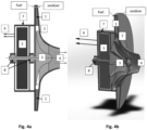
- Figs. 4 and 5 where the structural components of identical functions have the following identical reference numerals: 1 - detonation chamber, 2 - guides, 3 - turbine, 4 - outlet of incomplete combustion products from the turbine (to the main combustion chamber of the rocket engine), 5 - power generator (generator), 6 - electric cables for powering propellant pumps and possibly other on-board systems, 7 - device body, 8 - bearings of the turbinegenerator shaft system.
- the pre-combustion chamber of a liquid propellant rocket engine is a detonation chamber 1, in which a propellant mixture enriched with one of its components is continuously burned - in a rotating detonation mode, the chamber being arranged coaxially with a turbine 3 and a power generator 5 that powers electric motors (not shown) driving the fuel and oxidant pumps (not shown), and also with the outlet 4 of incomplete combustion products from the turbine 3 to the main combustion chamber (not shown) of the rocket engine.
- the pre-combustion chamber 1 has a form of a disk connected on one side to the device body 7 and protruding beyond its external circumference and on the other side forming a coaxial outlet 4 for incomplete combustion products passing through a centripetal turbine 3 mounted on a shaft equipped with the bearings 8 supporting also the power generator 5 built into the body 7.
- a cylindrical outer wall of the pre-combustion chamber 1 according to the invention there are circumferentially arranged inlets of the fuel and oxidant, preferably previously vaporized, and on its cylindrical inner wall there are guides 2 splitting a centripetal stream of exhaust gases and directing them to the blades of the centripetal turbine 3.
- the pre-combustion chamber 1 has the form of a ring mounted on an inner side of a device cylindrical body 7 and having a common external wall with the body 7, whereas a power generator 5 built into an interior of the body 7 and mounted on a shaft equipped with the bearings 8 together with an axial turbine 3 separating the body 7 from the outlet 4 of combustion products.
- inlets of the fuel and oxidant preferably previously vaporized, are arranged concentrically on the cylindrical ring base opposite to the outlet 4 of a stream of exhaust gases, where there are guides splitting the axial stream of exhaust gases and directing the same to the blades of the axial turbine 3.
- Electricity from the power generator 5 is directed through lines 6 to drive the fuel and oxidant pumps and possibly other electrical devices/systems of the rocket.
Landscapes
- Engineering & Computer Science (AREA)
- Chemical & Material Sciences (AREA)
- Combustion & Propulsion (AREA)
- Mechanical Engineering (AREA)
- General Engineering & Computer Science (AREA)
- Engine Equipment That Uses Special Cycles (AREA)
Abstract
Description
- The present invention relates to a pre-combustion chamber for feeding a turbine in a liquid propellant rocket engine.
- Various types of rockets are known, equipped in solid, liquid or hybrid chemical propellant engines or with electric propulsion engines (ion and plasma engines). Each type of the same has its own advantages that can be useful in the various launching and flight stages of rockets or their individual stages, space shuttles and satellites. The criteria for selecting a propulsion depend on aims set for individual elements of space objects and technical conditions necessary for their implementation.
- In liquid propellant rocket engines, the primary requirement is to ensure that the pumps supplying the propellants to the combustion chambers are sufficiently effective. In such engines, one of the methods of driving the pumps supplying the engine with liquid fuel and liquid oxidizer is the use of pre-combustion chambers, in which the incomplete combustion of both propellants is used to drive the turbines. Two solutions are used:
- ▪ a deflagration combustion of a fuel-rich mixture of propellants, carried out in a pre-combustion chamber, illustrated in the attached drawing
Fig. 1a , or - ▪ a deflagration combustion of an oxidant-rich mixture of propellants, carried out in the pre-combustion chamber, illustrated in the attached drawing
Fig. 1b . - In both cases, the composition of the mixture is selected so that the products of incomplete deflagration combustion have a temperature lower than the temperature admissible for feeding the turbines. The composition of incomplete combustion products allows their use in the main combustion chamber (closed combustion cycle), which improves the degree of fuel utilization. These systems are described in many manuals as well as they are available on the Internet [1-5]. Exemplary construction diagrams of such motors are shown in the accompanying drawing
Figs. 1-3 . - In the above known systems, a direct connection between the turbines and the propellant pumps is used. In practice, two types of solutions are used. In the first one, the gases from the pre-combustion chamber feed the turbine, which turbine through mechanical connections (gears), simultaneously drives both the fuel and oxidant pumps (
Fig. 1 ). More elaborated designs use separate pre-combustion chambers to drive the fuel pumps and the oxidant pumps (Fig. 2 ), allowing greater freedom in controlling the propellant composition in the main combustion chamber of the rocket engine. -
Fig. 3 shows the construction and operation of the SpaceX "Raptor" engine. This engine makes it possible to obtain unusually high pressures in the main combustion chamber. However, it requires cooling both the chamber and the outlet nozzle. In this solution, the fuel and oxidant pumps are supplied with the energy obtained in the pre-combustion chambers. - While the above solutions have significant advantages over previous liquid propellant engines, there are still areas where further improvements are possible.
- For the engines of the first stages of the rocket, it is possible to supply the engines driving the pumps of liquid propellants until the rocket launches from the ground power supply systems, which significantly simplifies and shortens the rocket engine starting cycle. However, this is an impractical solution and used only in relatively small rockets, because the engine on the launcher works only a few seconds until launch, and after detaching from the launcher - for a further few minutes, and then it must be powered from relatively heavy on-board batteries placed on the rocket, within the body of the rocket, which of course increase the rocket weight and at the same time reduce its load capacity.
- The aim of the present invention is to provide a new design of the propellant pre-combustion chamber, enabling simplification of the fuel and oxidant pumps supply system, which will reduce the weight of the system when compared to known classic solutions, and additionally allows greater flexibility of the engine operation, such as, for example, thrust control (the amount of a supplied fuel and oxidant) of a rocket engine at various stages of the rocket/shuttle flight, etc.
- Unexpectedly, it turned out that by using a detonation combustion of a mixture of fuel and oxidant in a pre-combustion chamber, it is possible to use the obtained energy to drive a single turbine and one electric energy generator supplying (with energy) separate electric motors for driving fuel and oxidant pumps. This ensures high flexibility in the operation of the pumps due to elimination of their mechanical coupling with the turbine, and at the same time reduces the weight of the entire power supply system and provides greater flexibility in rocket engine thrust control. The present invention significantly improves a supply of power for the rocket engine and simplifies its structure, eliminating energy losses in the pre-combustion stage.
- According to the invention, in a liquid propellant rocket engine, a pre-combustion chamber that provides energy for driving the fuel and oxidant pumps, is a detonation chamber in which - in a rotating detonation mode, the propellant mixture enriched with one of its components is continuously burned, the chamber being arranged coaxially with a turbine and a power generator that powers electric motors driving the fuel and oxidant pumps, and also with the outlet of incomplete combustion products from the turbine to the main combustion chamber of the rocket engine.
- According to the invention, the pre-combustion chamber has a form of a disc connected on one side to the device body and protruding beyond its external circumference and on the other side forming a coaxial outlet for incomplete combustion products passing through a centripetal turbine mounted on a bearing shaft supporting also the power generator built into the body. In a cylindrical outer wall of the pre-combustion chamber according to the invention, inlets of the fuel and oxidant, preferably previously vaporized, are arranged circumferentially, and on its cylindrical inner wall there are guides splitting a centripetal stream of exhaust gases and directing them to the centripetal turbine blades.
- Alternatively, the pre-combustion chamber has the form of a ring mounted on an inner side of the device cylindrical body and having a common external wall with the body, whereas a power generator is built into an interior of the body and mounted on a bearing shaft together with an axial turbine separating the body from the outlet of combustion products. In the annular pre-combustion chamber according to the invention, inlets of the fuel and oxidant, preferably previously vaporized, are arranged concentrically on the cylindrical ring base opposite to the outlet of a stream of exhaust gases, where there are guides splitting the axial stream of exhaust gases and directing the same to the axial turbine blades.
- Electrical current supplied through cables from the power generator, powers the fuel and oxidant pumps and possibly other electrical devices/systems of the rocket.
- First of all, the solution of the invention allows more flexible control of the pumps operation and of dosing components of the propellant powering the rocket engine by limiting the device structure to a single turbine and eliminating the rigid mechanical connection(s) between the turbine and the propellant pump(s) of the rocket engine. The simplified structure is lighter and more compact, which allows for better use of the space inside the rocket and for increase of the rocket load capacity. The generated electric current can optionally be used also for powering other devices/systems of the rocket and/or of the rocket stage. The incomplete combustion products leaving the turbine are burned in the main combustion chamber of the rocket engine.
- The invention is described below in more detail with reference to the accompanying drawing, where
Figs. 1 to 3 refer to prior art solutions and: -
Fig. 1a is a schematic diagram of a known rocket engine with a single pre-burner for propulsion of a turbine that drives fuel and oxidant pumps, wherein deflagration combustion of fuel-rich propellant takes place in the pre-burner; -
Fig. 1b is a schematic diagram of a known rocket engine with a single pre-burner for propulsion of a turbine that drives fuel and oxidant pumps, wherein the deflagration combustion of oxidant-rich propellant takes place in the pre-burner; -
Fig. 2 shows a schematic diagram of the known RS-25 rocket engine with separate pre-burners for driving the fuel and oxidizer pumps, in which pre-burners deflagration combustion of fuel-rich combustible mixture takes place; -
Fig. 3 shows a schematic diagram of the known "Raptor" rocket engine, in which two pre-burners are employed for deflagration combustion of enriched with fuel (in this case methane) combustible mixture in one of them and of a mixture enriched with oxidant (oxygen) in the other one; -
Fig. 4 is a schematic diagram of a disc detonation pre-combustion chamber for driving a turbine of a liquid propellant rocket engine, in an axial section (Fig. 4a ) and in a perspective and partial sectional view (Fig. 4b ); and -
Fig. 5 is a schematic diagram of an annular detonation pre-combustion chamber for driving a turbine of a liquid propellant rocket engine, in an axial section (Fig. 5a ) and in a perspective and partial sectional view (Fig. 5b ). - The pre-combustion chamber of a liquid propellant rocket engine provides energy for driving the fuel and oxidizer pumps. However, in the chamber, a propellant mixture is burned, in which the fuel or oxidant predominates, so as the combustion would utilize only a part of a component in excess, and thus would not lead to the combustion products temperature exceeding the acceptable turbine operating conditions. At the same time, the products - after supplementing the propellant mixture to optimum composition parameters from the point of view of combustion in the main combustion chamber of the rocket engine, need not to be removed as they can be burned in the main combustion chamber.
- Carrying the rotating detonation process in the pre-combustion chamber (pre-burner) of the rocket engine allows for a greater efficiency of the process, because in the detonation process, as opposed to a classic deflagration combustion, the pressure increases (the so-called Pressure Gain Combustion). In addition, due to the very high density of the released energy, the pre-burner is much smaller, more compact and in consequence also lighter. Therefore, the rotating detonation process taking place in the pre-burner of the engine allows for an improvement of the pre-burner efficiency and for an increase in performance of the rockets equipped with turbine propulsion systems of the kind.
- In a pre-combustion chamber according to the invention, in the rotating detonation process, a fuel and oxidant propellant mixture, preferably previously vaporized, is burned while having:
- ▪ a fuel-rich composition or alternatively an oxidant-rich composition;
whereas - ▪ the structure and dimensions of the chamber - in a disc or a ring form, can be easily adapted to the spatial conditions within the rocket and/or rocket stage, as well as to the desired efficiency of fuel and oxidizer pumps, taking into account the needs of the rocket, space shuttle or satellite; and
- ▪ the combustion products from the detonation pre-combustion chamber, used to power the turbine driving the power generator, provide sufficient energy to drive the fuel pump and the oxidizer pump, and possibly to generate an electricity excess for optional powering other components, devices and systems of the rocket apart from powering the propellant components pumps, although in the present solution according to the invention thus generated electricity serves mainly to improve the fuel and oxidizer pumps driving that is expected to consume approximately 98-99% of all energy produced in a generator powered by a single gas turbine.
- The subject matter of the invention is presented in
Figs. 4 and5 , where the structural components of identical functions have the following identical reference numerals: 1 - detonation chamber, 2 - guides, 3 - turbine, 4 - outlet of incomplete combustion products from the turbine (to the main combustion chamber of the rocket engine), 5 - power generator (generator), 6 - electric cables for powering propellant pumps and possibly other on-board systems, 7 - device body, 8 - bearings of the turbinegenerator shaft system. - In
Fig. 4 andFig. 5 , the pre-combustion chamber of a liquid propellant rocket engine is adetonation chamber 1, in which a propellant mixture enriched with one of its components is continuously burned - in a rotating detonation mode, the chamber being arranged coaxially with aturbine 3 and apower generator 5 that powers electric motors (not shown) driving the fuel and oxidant pumps (not shown), and also with theoutlet 4 of incomplete combustion products from theturbine 3 to the main combustion chamber (not shown) of the rocket engine. - According to the invention (
Fig. 4 ), thepre-combustion chamber 1 has a form of a disk connected on one side to thedevice body 7 and protruding beyond its external circumference and on the other side forming acoaxial outlet 4 for incomplete combustion products passing through acentripetal turbine 3 mounted on a shaft equipped with thebearings 8 supporting also thepower generator 5 built into thebody 7. In a cylindrical outer wall of thepre-combustion chamber 1 according to the invention, there are circumferentially arranged inlets of the fuel and oxidant, preferably previously vaporized, and on its cylindrical inner wall there areguides 2 splitting a centripetal stream of exhaust gases and directing them to the blades of thecentripetal turbine 3. - Alternatively (
Fig. 5 ), thepre-combustion chamber 1 has the form of a ring mounted on an inner side of a devicecylindrical body 7 and having a common external wall with thebody 7, whereas apower generator 5 built into an interior of thebody 7 and mounted on a shaft equipped with thebearings 8 together with anaxial turbine 3 separating thebody 7 from theoutlet 4 of combustion products. In the annularpre-combustion chamber 1 according to the invention, inlets of the fuel and oxidant, preferably previously vaporized, are arranged concentrically on the cylindrical ring base opposite to theoutlet 4 of a stream of exhaust gases, where there are guides splitting the axial stream of exhaust gases and directing the same to the blades of theaxial turbine 3. - Electricity from the
power generator 5 is directed throughlines 6 to drive the fuel and oxidant pumps and possibly other electrical devices/systems of the rocket. -
- 1. Sutton G. P., Biblarz O., Rocket propulsion elements, A Wiley-Interscience Publication JOHN WILEY & SONS, INC. New York / Chichester / Weinheim / Brisbane / Singapore / Toronto (7th ed. 2000);
- 2. https://en.wikipedia.org/wiki/Staged_combustion_cycle;
- 3. Wolanski P., "Detonative Propulsion", Proceedings of the Combustion Institute, 34, pp.125-158, Elsevier (2013);
- 4. Wolanski P. (Ed.), "Research on detonative propulsion in Poland", Institute of Aviation Scientific Publication No. 60, Warsaw: tukasiewicz Research Network - Institute of Aviation, 2021. ISBN 978-83-63539-45-0.
Claims (6)
- A pre-combustion chamber in a liquid propellants rocket engine, providing energy for driving fuel and oxidizer pumps, characterized in that it is a detonation chamber (1) in which - in a rotating detonation mode, the propellant mixture enriched in one of its components is continuously burned, the chamber being arranged coaxially with a turbine (3) and a power generator (5) that powers electric motors driving the fuel and oxidant pumps, and also with the outlet (4) of incomplete combustion products from the turbine (3) to the main combustion chamber of the rocket engine.
- The pre-combustion chamber according to claim 1, characterized in that it has a form of a disk connected on one side to the device body (7) and extending beyond its external circumference, on the other side forming a coaxial outlet (4) for incomplete combustion products passing through a centripetal turbine (3) mounted on a shaft equipped with the bearings (8), the shaft supporting also the power generator (5), built into the body (7).
- The pre-combustion chamber according to claim 1, characterized in that the inlets of the fuel and oxidant, preferably previously vaporized, are circumferentially arranged in the cylindrical outer wall of the pre-combustion chamber (1), and on its cylindrical inner wall there are guides (2) splitting a centripetal stream of exhaust gases and directing them to the blades of the centripetal turbines (3).
- The pre-combustion chamber according to claim 1, characterized in that it has a form of a ring mounted on an inner side of the device cylindrical body (7) and having a common external wall with the body (7), whereas the power generator (5) is built into an interior of the body (7) and mounted on a shaft equipped with the bearings (8) together with an axial a turbine (3) separating the body (7) from the outlet (4) of combustion products.
- The pre-combustion chamber according to claim 1, characterized in that the inlets of the fuel and oxidant, preferably previously vaporized, are arranged concentrically on the cylindrical ring base opposite to the outlet (4) of a stream of exhaust gases, where there are guides (2) splitting the axial stream of exhaust gases and directing them to the blades of the axial turbine (3).
- The pre-combustion chamber according to any one of the claims 1 to 5, characterized in that electricity from the power generator (5) is directed via the lines (6) to drive the fuel and oxidant pumps and possibly other electrical devices/systems on board.
Applications Claiming Priority (1)
| Application Number | Priority Date | Filing Date | Title |
|---|---|---|---|
| PL439009A PL439009A1 (en) | 2021-09-22 | 2021-09-22 | Pre-combustion chamber for powering the turbine in liquid propellant rocket engines |
Publications (2)
| Publication Number | Publication Date |
|---|---|
| EP4155612A1 true EP4155612A1 (en) | 2023-03-29 |
| EP4155612B1 EP4155612B1 (en) | 2026-01-21 |
Family
ID=84358168
Family Applications (1)
| Application Number | Title | Priority Date | Filing Date |
|---|---|---|---|
| EP22020455.6A Active EP4155612B1 (en) | 2021-09-22 | 2022-09-22 | Pre-combustion chamber for feeding a turbine in a liquid propellant rocket engine |
Country Status (2)
| Country | Link |
|---|---|
| EP (1) | EP4155612B1 (en) |
| PL (1) | PL439009A1 (en) |
Cited By (2)
| Publication number | Priority date | Publication date | Assignee | Title |
|---|---|---|---|---|
| CN118375532A (en) * | 2024-06-24 | 2024-07-23 | 北京航空航天大学 | Turbine pump pressure type solid-liquid hybrid rocket engine system |
| CN119844241A (en) * | 2025-03-18 | 2025-04-18 | 北京天兵科技有限公司 | Heat exchanger, rocket engine and rocket of integrated design with precombustor |
Citations (6)
| Publication number | Priority date | Publication date | Assignee | Title |
|---|---|---|---|---|
| FR2232685A1 (en) * | 1973-06-09 | 1975-01-03 | Messerschmitt Boelkow Blohm | Fluid drive system for rockets - with pre-combustion chamber to raise oxydator-rich gas mixture, and based on main drive electrical system |
| DE4234248A1 (en) * | 1992-10-10 | 1994-04-14 | Asea Brown Boveri | Gas turbine group |
| US7150143B2 (en) * | 2003-07-21 | 2006-12-19 | General Electric Company | Hybrid fuel cell-pulse detonation power system |
| US9021783B2 (en) * | 2012-10-12 | 2015-05-05 | United Technologies Corporation | Pulse detonation engine having a scroll ejector attenuator |
| CN106285945A (en) * | 2016-10-28 | 2017-01-04 | 清华大学 | Rotate pinking electromotor continuously |
| US20190128529A1 (en) * | 2017-10-27 | 2019-05-02 | General Electric Company | Multi-can annular rotating detonation combustor |
-
2021
- 2021-09-22 PL PL439009A patent/PL439009A1/en unknown
-
2022
- 2022-09-22 EP EP22020455.6A patent/EP4155612B1/en active Active
Patent Citations (6)
| Publication number | Priority date | Publication date | Assignee | Title |
|---|---|---|---|---|
| FR2232685A1 (en) * | 1973-06-09 | 1975-01-03 | Messerschmitt Boelkow Blohm | Fluid drive system for rockets - with pre-combustion chamber to raise oxydator-rich gas mixture, and based on main drive electrical system |
| DE4234248A1 (en) * | 1992-10-10 | 1994-04-14 | Asea Brown Boveri | Gas turbine group |
| US7150143B2 (en) * | 2003-07-21 | 2006-12-19 | General Electric Company | Hybrid fuel cell-pulse detonation power system |
| US9021783B2 (en) * | 2012-10-12 | 2015-05-05 | United Technologies Corporation | Pulse detonation engine having a scroll ejector attenuator |
| CN106285945A (en) * | 2016-10-28 | 2017-01-04 | 清华大学 | Rotate pinking electromotor continuously |
| US20190128529A1 (en) * | 2017-10-27 | 2019-05-02 | General Electric Company | Multi-can annular rotating detonation combustor |
Non-Patent Citations (3)
| Title |
|---|
| "Research on detonative propulsion in Poland", INSTITUTE OF AVIATION SCIENTIFIC PUBLICATION |
| SUTTON G. PBIBLARZ O.: "Rocket propulsion elements", 2000, JOHN WILEY & SONS, INC |
| WOLANSKI P.: "Proceedings of the Combustion Institute", vol. 34, 2013, ELSEVIER, article "Detonative Propulsion", pages: 125 - 158 |
Cited By (2)
| Publication number | Priority date | Publication date | Assignee | Title |
|---|---|---|---|---|
| CN118375532A (en) * | 2024-06-24 | 2024-07-23 | 北京航空航天大学 | Turbine pump pressure type solid-liquid hybrid rocket engine system |
| CN119844241A (en) * | 2025-03-18 | 2025-04-18 | 北京天兵科技有限公司 | Heat exchanger, rocket engine and rocket of integrated design with precombustor |
Also Published As
| Publication number | Publication date |
|---|---|
| EP4155612B1 (en) | 2026-01-21 |
| PL439009A1 (en) | 2023-03-27 |
Similar Documents
| Publication | Publication Date | Title |
|---|---|---|
| US9920689B2 (en) | Hybrid wave rotor propulsion system | |
| EP3447274B1 (en) | Electric power-assisted liquid-propellant rocket propulsion system | |
| EP4155612B1 (en) | Pre-combustion chamber for feeding a turbine in a liquid propellant rocket engine | |
| US4815277A (en) | Integrated power unit | |
| US10429154B2 (en) | Energy weapon having a fast start turbine for a high power generator | |
| US9951694B2 (en) | System and method for emergency starting of an aircraft turbomachine | |
| US9650997B2 (en) | Rotary turbo rocket | |
| WO2013024361A2 (en) | Improved rocket engine systems and devices | |
| US4819423A (en) | Integrated power unit | |
| US20060086078A1 (en) | Universal Carnot propulsion systems for turbo rocketry | |
| US10738697B2 (en) | Parallel combustor configuration for unmanned underwater vehicle propulsion turbine | |
| EP4607021A2 (en) | Integrated electro-aero-thermal engine | |
| JP2010540830A (en) | Device for powering rocket engine pumps using inertial disks | |
| RU2520771C1 (en) | Liquid-propellant engine with generator gas staged combustion cycle | |
| CN111043042A (en) | Electric pump device of liquid rocket | |
| RU2476709C1 (en) | Liquid propellant rocket engine | |
| EP4202200B1 (en) | A rocket engine with multi-stage combustion of a mixture of propellants | |
| RU2484285C1 (en) | Oxygen-hydrogen liquid-propellant engine | |
| RU2387582C2 (en) | Complex for reactive flight | |
| US12214889B2 (en) | Integral propulsion and auxiliary power generation system for rocket engine powered aircraft | |
| RU2594828C1 (en) | Propulsion engine of supersonic aircraft | |
| RU2490173C1 (en) | Vtol aircraft | |
| US20150211445A1 (en) | Missile having a turbine-compressing means-unit | |
| RU2481488C1 (en) | Three-component liquid-propellant engine | |
| RU2476708C1 (en) | Liquid propellant rocket engine |
Legal Events
| Date | Code | Title | Description |
|---|---|---|---|
| PUAI | Public reference made under article 153(3) epc to a published international application that has entered the european phase |
Free format text: ORIGINAL CODE: 0009012 |
|
| STAA | Information on the status of an ep patent application or granted ep patent |
Free format text: STATUS: THE APPLICATION HAS BEEN PUBLISHED |
|
| AK | Designated contracting states |
Kind code of ref document: A1 Designated state(s): AL AT BE BG CH CY CZ DE DK EE ES FI FR GB GR HR HU IE IS IT LI LT LU LV MC MK MT NL NO PL PT RO RS SE SI SK SM TR |
|
| STAA | Information on the status of an ep patent application or granted ep patent |
Free format text: STATUS: REQUEST FOR EXAMINATION WAS MADE |
|
| 17P | Request for examination filed |
Effective date: 20230929 |
|
| RBV | Designated contracting states (corrected) |
Designated state(s): AL AT BE BG CH CY CZ DE DK EE ES FI FR GB GR HR HU IE IS IT LI LT LU LV MC MK MT NL NO PL PT RO RS SE SI SK SM TR |
|
| STAA | Information on the status of an ep patent application or granted ep patent |
Free format text: STATUS: EXAMINATION IS IN PROGRESS |
|
| 17Q | First examination report despatched |
Effective date: 20240711 |
|
| GRAP | Despatch of communication of intention to grant a patent |
Free format text: ORIGINAL CODE: EPIDOSNIGR1 |
|
| STAA | Information on the status of an ep patent application or granted ep patent |
Free format text: STATUS: GRANT OF PATENT IS INTENDED |
|
| INTG | Intention to grant announced |
Effective date: 20250902 |
|
| GRAS | Grant fee paid |
Free format text: ORIGINAL CODE: EPIDOSNIGR3 |
|
| GRAA | (expected) grant |
Free format text: ORIGINAL CODE: 0009210 |
|
| STAA | Information on the status of an ep patent application or granted ep patent |
Free format text: STATUS: THE PATENT HAS BEEN GRANTED |
|
| AK | Designated contracting states |
Kind code of ref document: B1 Designated state(s): AL AT BE BG CH CY CZ DE DK EE ES FI FR GB GR HR HU IE IS IT LI LT LU LV MC MK MT NL NO PL PT RO RS SE SI SK SM TR |
|
| REG | Reference to a national code |
Ref country code: CH Ref legal event code: F10 Free format text: ST27 STATUS EVENT CODE: U-0-0-F10-F00 (AS PROVIDED BY THE NATIONAL OFFICE) Effective date: 20260121 |
|
| REG | Reference to a national code |
Ref country code: DE Ref legal event code: R096 Ref document number: 602022028685 Country of ref document: DE |
|
| REG | Reference to a national code |
Ref country code: IE Ref legal event code: FG4D |