EP4155592A1 - Ventileinrichtung, sowie fahrzeug mit einer luftfederungseinrichtung - Google Patents
Ventileinrichtung, sowie fahrzeug mit einer luftfederungseinrichtung Download PDFInfo
- Publication number
- EP4155592A1 EP4155592A1 EP22195077.7A EP22195077A EP4155592A1 EP 4155592 A1 EP4155592 A1 EP 4155592A1 EP 22195077 A EP22195077 A EP 22195077A EP 4155592 A1 EP4155592 A1 EP 4155592A1
- Authority
- EP
- European Patent Office
- Prior art keywords
- valve
- compressed air
- air channel
- actuated
- valves
- Prior art date
- Legal status (The legal status is an assumption and is not a legal conclusion. Google has not performed a legal analysis and makes no representation as to the accuracy of the status listed.)
- Granted
Links
Images

Classifications
-
- B—PERFORMING OPERATIONS; TRANSPORTING
- B60—VEHICLES IN GENERAL
- B60G—VEHICLE SUSPENSION ARRANGEMENTS
- B60G17/00—Resilient suspensions having means for adjusting the spring or vibration-damper characteristics, for regulating the distance between a supporting surface and a sprung part of vehicle or for locking suspension during use to meet varying vehicular or surface conditions, e.g. due to speed or load
- B60G17/02—Spring characteristics, e.g. mechanical springs and mechanical adjusting means
- B60G17/04—Spring characteristics, e.g. mechanical springs and mechanical adjusting means fluid spring characteristics
- B60G17/052—Pneumatic spring characteristics
- B60G17/0523—Regulating distributors or valves for pneumatic springs
- B60G17/0525—Height adjusting or levelling valves
-
- F—MECHANICAL ENGINEERING; LIGHTING; HEATING; WEAPONS; BLASTING
- F16—ENGINEERING ELEMENTS AND UNITS; GENERAL MEASURES FOR PRODUCING AND MAINTAINING EFFECTIVE FUNCTIONING OF MACHINES OR INSTALLATIONS; THERMAL INSULATION IN GENERAL
- F16K—VALVES; TAPS; COCKS; ACTUATING-FLOATS; DEVICES FOR VENTING OR AERATING
- F16K11/00—Multiple-way valves, e.g. mixing valves; Pipe fittings incorporating such valves
- F16K11/10—Multiple-way valves, e.g. mixing valves; Pipe fittings incorporating such valves with two or more closure members not moving as a unit
- F16K11/14—Multiple-way valves, e.g. mixing valves; Pipe fittings incorporating such valves with two or more closure members not moving as a unit operated by one actuating member, e.g. a handle
- F16K11/16—Multiple-way valves, e.g. mixing valves; Pipe fittings incorporating such valves with two or more closure members not moving as a unit operated by one actuating member, e.g. a handle which only slides, or only turns, or only swings in one plane
- F16K11/163—Multiple-way valves, e.g. mixing valves; Pipe fittings incorporating such valves with two or more closure members not moving as a unit operated by one actuating member, e.g. a handle which only slides, or only turns, or only swings in one plane only turns
- F16K11/165—Multiple-way valves, e.g. mixing valves; Pipe fittings incorporating such valves with two or more closure members not moving as a unit operated by one actuating member, e.g. a handle which only slides, or only turns, or only swings in one plane only turns with the rotating spindles parallel to the closure members
-
- F—MECHANICAL ENGINEERING; LIGHTING; HEATING; WEAPONS; BLASTING
- F16—ENGINEERING ELEMENTS AND UNITS; GENERAL MEASURES FOR PRODUCING AND MAINTAINING EFFECTIVE FUNCTIONING OF MACHINES OR INSTALLATIONS; THERMAL INSULATION IN GENERAL
- F16K—VALVES; TAPS; COCKS; ACTUATING-FLOATS; DEVICES FOR VENTING OR AERATING
- F16K31/00—Actuating devices; Operating means; Releasing devices
- F16K31/12—Actuating devices; Operating means; Releasing devices actuated by fluid
- F16K31/122—Actuating devices; Operating means; Releasing devices actuated by fluid the fluid acting on a piston
- F16K31/1221—Actuating devices; Operating means; Releasing devices actuated by fluid the fluid acting on a piston one side of the piston being spring-loaded
-
- F—MECHANICAL ENGINEERING; LIGHTING; HEATING; WEAPONS; BLASTING
- F16—ENGINEERING ELEMENTS AND UNITS; GENERAL MEASURES FOR PRODUCING AND MAINTAINING EFFECTIVE FUNCTIONING OF MACHINES OR INSTALLATIONS; THERMAL INSULATION IN GENERAL
- F16K—VALVES; TAPS; COCKS; ACTUATING-FLOATS; DEVICES FOR VENTING OR AERATING
- F16K31/00—Actuating devices; Operating means; Releasing devices
- F16K31/12—Actuating devices; Operating means; Releasing devices actuated by fluid
- F16K31/122—Actuating devices; Operating means; Releasing devices actuated by fluid the fluid acting on a piston
- F16K31/1223—Actuating devices; Operating means; Releasing devices actuated by fluid the fluid acting on a piston one side of the piston being acted upon by the circulating fluid
-
- F—MECHANICAL ENGINEERING; LIGHTING; HEATING; WEAPONS; BLASTING
- F16—ENGINEERING ELEMENTS AND UNITS; GENERAL MEASURES FOR PRODUCING AND MAINTAINING EFFECTIVE FUNCTIONING OF MACHINES OR INSTALLATIONS; THERMAL INSULATION IN GENERAL
- F16K—VALVES; TAPS; COCKS; ACTUATING-FLOATS; DEVICES FOR VENTING OR AERATING
- F16K31/00—Actuating devices; Operating means; Releasing devices
- F16K31/44—Mechanical actuating means
- F16K31/52—Mechanical actuating means with crank, eccentric, or cam
- F16K31/524—Mechanical actuating means with crank, eccentric, or cam with a cam
- F16K31/52475—Mechanical actuating means with crank, eccentric, or cam with a cam comprising a sliding valve
- F16K31/52483—Mechanical actuating means with crank, eccentric, or cam with a cam comprising a sliding valve comprising a multiple-way sliding valve
-
- B—PERFORMING OPERATIONS; TRANSPORTING
- B60—VEHICLES IN GENERAL
- B60G—VEHICLE SUSPENSION ARRANGEMENTS
- B60G2300/00—Indexing codes relating to the type of vehicle
- B60G2300/02—Trucks; Load vehicles
- B60G2300/026—Heavy duty trucks
-
- B—PERFORMING OPERATIONS; TRANSPORTING
- B60—VEHICLES IN GENERAL
- B60G—VEHICLE SUSPENSION ARRANGEMENTS
- B60G2500/00—Indexing codes relating to the regulated action or device
- B60G2500/20—Spring action or springs
- B60G2500/202—Height or leveling valve for air-springs
-
- B—PERFORMING OPERATIONS; TRANSPORTING
- B60—VEHICLES IN GENERAL
- B60G—VEHICLE SUSPENSION ARRANGEMENTS
- B60G2500/00—Indexing codes relating to the regulated action or device
- B60G2500/30—Height or ground clearance
-
- B—PERFORMING OPERATIONS; TRANSPORTING
- B60—VEHICLES IN GENERAL
- B60G—VEHICLE SUSPENSION ARRANGEMENTS
- B60G2600/00—Indexing codes relating to particular elements, systems or processes used on suspension systems or suspension control systems
- B60G2600/20—Manual control or setting means
Definitions
- the invention relates to a valve device and a vehicle with an air suspension device that has such a valve device.
- the valve device is designed, for example, as a level control valve for an air suspension device of a truck.
- Air suspension devices for trucks have been known for many years and are used in particular in the upper tonnage segment for goods transport.
- the advantages are in particular an optimal suspension independent of the road and load condition, which leads to an increase in driving comfort and protection of the load.
- This level control valve should always be operable, even if there is no electrical or pneumatic supply.
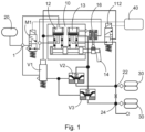
- the air suspension device has a compressed air inlet 1 via which compressed air is supplied from an air reservoir 20 to the air suspension device. This compressed air is applied to the air suspension control valve 10, through which ventilation and venting of air spring bellows 30 via ventilation connections 22, 24 can be controlled via valves V1, V2 and V3 of the air suspension device.
- the air suspension control valve 10 has two valves 12, 13, the ventilation being controlled via the valve 12 and the ventilation of the air spring bellows 30 being controlled via the valve 13.
- the air suspension control valve 10 is here both via a electronic control unit 40, through which the solenoid valves M1, M2 can be actuated for control, and can also be controlled via a hand lever 14.
- the air suspension control valve 10 also has an RTR control 16 (RTR: Return-To-Ride) via which the vehicle body can be automatically brought to a safe driving level.
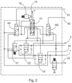
- a circuit diagram of the air suspension device 1 is in the 2 shown.
- the solenoid valves M1, M2 are controlled via electrical connections 61, 62.
- the air suspension device receives compressed air via the compressed air inlet 1, and the air suspension control valve 10 controls the ventilation connections 22, 24, the air spring bellows in which 2 not shown.
- the air bags are vented via the vent outlet 3.
- the other reference symbols correspond to those of 1 .
- the air suspension control valve 10 has a relatively complicated structure and is therefore expensive to manufacture. It has relatively large dimensions and its length in particular can lead to problems with the piping in practice. It also has the disadvantage that it does not offer any possibility for a defined limitation of the upper and/or lower level by the control unit 40 if an operator wants to manually raise the vehicle body above an upper permissible level, for example.
- Another prior art air suspension device uses an air suspension control valve with a pneumatic controller and pneumatic buttons for manual lifting and lowering of the truck.
- This air suspension device also has the disadvantage that lifting has priority in the event of conflicting control commands.
- Another disadvantage of this system is that a reservoir pressure is required to lower the vehicle body.
- the object of the invention is therefore to specify such a valve device and a vehicle with such a valve device.
- valve device according to claim 1 and a vehicle according to claim 10.
- the invention relates to a valve device, in particular for a vehicle, comprising a housing with a first valve and a second valve; wherein the housing has a compressed air inlet, a compressed air outlet and a ventilation outlet and each of the valves comprises a piston and a return spring and the valve device has no flow in a basic position when it is not actuated, and the valve device has a mechanical control for actuating the valves having at least one manual operating element and an electropneumatic control, and the first valve is configured as a ventilation valve and the second valve as a vent valve, and wherein both valves block when both controls are actuated.
- the second valve within the housing is connected to the first valve via two pneumatic connections in such a way that when the first valve is actuated, compressed air is passed from the compressed air inlet through the first and second valve to the compressed air outlet, and when the second valve is actuated, compressed air is conveyed from the Compressed air outlet is passed through the second and first valve to the vent outlet.
- first valve and the second valve are connected in series via two pneumatic connections, and the pneumatic connections between the first valve and the second valve are inverted.
- the first valve is a 4/2 valve and the second valve is a 4/2 or a 3/2 valve.
- the first valve contains a piston which has a first compressed air channel for a ventilation process and a second compressed air channel for a venting process, and with the first compressed air channel being blocked when the first valve is not actuated and the second compressed air channel being open and when the first valve is actuated Valve of the first compressed air channel is open and the second compressed air channel is blocked.
- the second valve contains a piston which has a third compressed air channel for a ventilation process and a fourth compressed air channel for a venting process, and with the third compressed air channel being open when the second valve is not actuated and the fourth compressed air channel being blocked and when the second valve is actuated Valve of the third compressed air channel is blocked and the fourth compressed air channel is open.
- the first compressed air channel when the first valve is actuated, the first compressed air channel is connected to the third compressed air channel via the first pneumatic connection, and when the second valve is actuated, the fourth compressed air channel is connected to the second compressed air channel via the second pneumatic connection.
- the mechanical control comprises two buttons and two tappets, or a lever, a shaft, a cam disc, a torsion spring and one tappet each for the valves.
- the electropneumatic control for each of the valves includes a solenoid valve for controlling a compressed air supply for the valves.
- valve device according to the invention can advantageously be used for a vehicle, in particular a truck, and trailer vehicles with an air suspension device.
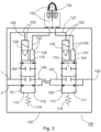
- FIG. 3 shows schematically a valve device 100 with a housing 102 in which a first valve 110 and a second valve 111 are arranged and which has a compressed air inlet 1 for a compressed air supply, a compressed air outlet 104 and a ventilation outlet 3 .
- the first valve 110 is in particular a ventilation valve and has a connection which is connected to the compressed air inlet 1 and a connection which is connected to the ventilation outlet 3 .
- the second valve 111 is in particular a vent valve and has two ports which are connected to two ports of the valve 111 via two pneumatic connections 106 , 107 within the valve device 100 , and two ports which are connected to the compressed air outlet 104 .
- the pneumatic connections 106, 107 and the connections of the valves 110, 111 are designed in particular such that upon actuation of the valve 110 compressed air from the compressed air inlet 1 through the Valves 110, 111 is passed through to the compressed air outlet 104 and when the valve 111 is actuated, compressed air is passed through the compressed air air outlet 104 through the valves 110, 111 to the vent outlet 3.
- the two valves 110, 111 are 4/2 valves in this embodiment and each have a piston 112 and 113, respectively, in which 1 shown only schematically, each with a return spring 114 or 115, and a valve housing 116 or 117, in each of which the piston 112 or 113 moves.
- the valve 111 can also be designed as a 3/2 valve with only one connection for the compressed air outlet 104 .
- a valve device of this type can be used in particular for air suspension systems in motor vehicles. If the valve 110 is actuated and its piston 112 is thereby displaced, a pressure for air suspension is built up via the connections 1 and 104 . If valve 111 is actuated and its piston 113 is displaced, pressure is released via connections 104 and 3. If none of the valves 110, 111 are actuated, the pressure at the compressed air outlet 104 is maintained.
- the valve 110 is designed in such a way that in a basic position it enables ventilation through the valves 110 and 111 and when the valve 110 is actuated it enables ventilation via the valves 110 and 111 .
- the valve 111 is designed in such a way that in a basic position it enables ventilation through the valves 110 and 111 and when the valve 111 is actuated it enables venting via the valves 110 and 111 . If both valves 110, 111 are actuated, there is no flow.
- each of the valves 110, 111 has both an electropneumatic control 120 and a mechanical control 122 for controlling a compressed air supply and a vent.
- the electropneumatic control 120 has a solenoid valve 124 and a pneumatic line 126 for the valve 110 and a solenoid valve 125 and a pneumatic line 127 for the valve 111.
- the mechanical Control 122 has a manual control element, for example with a lever or two buttons.
- the solenoid valves 124, 125 can, for example, by an electronic control unit in which 3 not shown, are operated.
- the mechanical control 122 contains the mechanical control 122 a plunger 130 for the valve 110 and a plunger 131 for the valve 111.
- the mechanical control 122 has a rotary mechanism 132 with a lever in which 3 not shown, on.
- the rotary mechanism 132 contains, for example, a cam disk, via which the plunger 130 moves the piston 112 when the lever is rotated in one direction of rotation, and via which the plunger 131 moves the piston 113 when the lever is rotated in the other direction of rotation.
- the valve device 100 has the property that the valve device 100 is guided into a stop position in the event of simultaneous opposing operation by the control device and by manual operation.
- both pistons 112, 113 are displaced so that there is no flow through the valve device 100.
- the piston 112 of the first valve 110 contains the piston 112 of the first valve 110 a first compressed air channel 150 for a ventilation process and a second compressed air channel 151 for a venting process.
- the compressed air ducts 150, 151 are configured such that when the first valve 110 is not actuated, the first compressed air duct 150 is blocked and the second compressed air duct 151 is open, and when the first valve 110 is actuated, the first compressed air duct 150 is opened and the second compressed air duct 151 is blocked .
- the piston 113 of the second valve 111 contains a third compressed air channel 152 for a ventilation process and a fourth compressed air channel 153 for a venting process.
- the compressed air channels 152, 153 are designed in such a way that when the second valve 111 is not actuated, the third compressed air channel 152 is open and the fourth compressed air channel 153 is blocked, and when the second valve 111 is actuated, the third compressed air channel 152 is blocked and the fourth compressed air channel 153 is open.
- the pneumatic connection 106 connects the first compressed air channel 150 to the third compressed air channel 152, so that ventilation takes place, and when the second valve 111 is actuated, the pneumatic connection 107 connects the fourth compressed air channel 153 to the second compressed air channel 151, so that venting takes place.
- valve device 100 By using two 4/2 valves or a 4/2 and a 3/2 valve, the circuit of the valve device 100 is significantly simplified compared to known valve devices of this type, so that a significant reduction in costs and a reduction in the dimensions is made possible. This reduces the system costs, for example for trailer vehicles with electronically controlled air suspension, and makes these systems more attractive to customers.
- FIG 4 A preferred embodiment of the valve device 100 is shown in FIG 4 shown in a plan.
- the solenoid valves 124, 125 of the valve device 100 are arranged on one side of the housing 102 in this case.
- the mechanical control 122 of 3 whose plunger in the housing 102 are integrated, in this case has a lever 140 which can be actuated by an operator.
- the valve device 100 of 4 is in the figure 5 shown in a cross section through a cutting axis B - B of the valve device 100.
- the two valves 110, 111 are arranged in the housing 102 of the valve device 100, the valve housings of the valves 110, 111 being configured essentially by the housing 102.
- the pistons 112 and 113 are each displaceable via the plungers 130 and 131 by the lever 140 of the mechanical control 122 .
- the mechanical control 122 also has a shaft 142 , a cam disc 144 and a torsion spring 146 .
- the cam disk 144 is fastened to the shaft 142 and when the lever 140 is actuated, either the plunger 130 or the plunger 131 is displaced by the cam disk 144 .
- a rotary movement of the lever 140 is converted into a translatory movement by the cam disk 144 .
- the torsion spring 146 causes a force in the direction of the basic position of the lever 140, in which no force acts on any of the plungers 130, 131.
- the cam disk 144 has a surface with a control such that when the lever 140 is actuated in one direction of rotation, for example clockwise, the plunger 130 and thereby the piston 112 are displaced and when the lever 140 is actuated in the other direction Direction of rotation, counterclockwise, the plunger 131 and thereby the piston 113 is displaced. Actuation of the lever 140 clockwise causes an aeration process by means of the valve 110 and actuation of the lever 140 counterclockwise causes a venting process by means of the valve 111. If the lever 140 is in the basic position, the set pressure is maintained.
- the pistons 112, 113 are arranged axially to the shaft 142.
- One of the tappets 130, 131 and thereby one of the pistons 112, 113 of the first or second valve 110, 111 can be actuated.
- the lever 140 is actuated, a transformation from a rotary to a translatory movement is carried out.
- each lever position can be assigned a defined piston position. Only a partial displacement of one of the pistons 112, 113 leads to a reduced flow through the valve device 100.
Landscapes
- Engineering & Computer Science (AREA)
- General Engineering & Computer Science (AREA)
- Mechanical Engineering (AREA)
- Vehicle Body Suspensions (AREA)
Abstract
Description
- Die Erfindung betrifft eine Ventileinrichtung sowie ein Fahrzeug mit einer Luftfederungseinrichtung, die eine derartige Ventileinrichtung aufweist. Die Ventileinrichtung ist beispielsweise als ein Niveauregulierungsventil für eine Luftfederungseinrichtung eines Lastkraftfahrzeugs ausgestaltet.
- Luftfederungseinrichtungen für Lastkraftfahrzeuge sind seit vielen Jahren bekannt und werden insbesondere im oberen Tonnagesegment für den Gütertransport verwendet. Vorteile sind insbesondere eine optimale Federung unabhängig vom Straßen- und Beladungszustand, die zur Erhöhung des Fahrkomforts und Schonung des Ladeguts führt.
- Moderne, elektronisch geregelte Luftfederungseinrichtungen dieser Art verwenden elektrische und/oder pneumatisch arbeitende Ansteuerungen für eine Steuerung von Luftfederbälgen und weisen üblicherweise auch ein mit der Hand zu betätigendes Niveauregulierungsventil auf, das vier Stellungen aufweist:
- Heben: die Luftfederbälge werden aus einem Luftvorrat belüftet,
- Senken: die Luftfederbälge werden an die Umgebung entlüftet,
- Stoppstellung: die Luftfederbälge sind von der Umgebung und dem Luftvorrat abgeschnitten, und
- Fahrtstellung: die Luftfederbälge sind mit einem Luftfederventil verbunden.
- Dieses Niveauregulierungsventil soll immer, also auch bei einer fehlenden elektrischen und pneumatischen Versorgung, bedienbar sein.
- Durch das gleichzeitige Vorhandensein mehrerer Kontrollmöglichkeiten benötigt man, um einen sicheren Betrieb des Lastkraftfahrzeugs zu gewährleisten, ein definiertes Verhalten im Falle von gegensätzlichen Kontrollbefehlen. Folgende
- Szenarien sind hierbei denkbar, bei denen gegensätzliche Kontrollbefehle auftreten können:
- 1) Das Fahrzeug wird durch die elektronische Luftfederungseinrichtung gesenkt. Der Fahrer erkennt jedoch, dass ein Mensch unter dem Anhänger liegt. Der Fahrer möchte daher die Bewegung durch intuitive Betätigung des Bedienelements in die Heben-Stellung stoppen.
- 2) Das Fahrzeug wird durch die elektronische Luftfederungseinrichtung gehoben. Der Fahrer erkennt jedoch, dass das Fahrzeug gleich unter die Werkstattdecke stößt. Der Fahrer möchte daher die Bewegung durch intuitive Betätigung des Bedienelements in die Senken-Stellung stoppen.
- 3) Der Fahrer hebt das Fahrzeug über das Bedienelement, jedoch ist das zulässige obere Niveau erreicht. Die elektronische Luftfederungseinrichtung kann daher den Hebevorgang stoppen.
- 4) Der Fahrer senkt das Fahrzeug über das Bedienelement, jedoch ist das zulässige untere Niveau erreicht. Die elektronische Luftfederungseinrichtung kann daher den Senkvorgang stoppen.
- Ein prinzipieller Aufbau einer Luftfederungseinrichtung für ein Lastkraftfahrzeug nach dem Stand der Technik, die sowohl eine elektronische Niveauregelung als auch eine manuelle Steuerung per Handhebel über ein Luftfederungs-Regelventil 10 an einem Fahrzeug ermöglicht, ist in der
Fig. 1 dargestellt. Die Luftfederungseinrichtung weist einen Drucklufteinlass 1 auf, über den der Luftfederungseinrichtung aus einem Luftreservoir 20 Druckluft zugeführt wird. Diese Druckluft liegt an dem Luftfederungs-Regelventil 10 an, durch das über Ventile V1, V2 und V3 der Luftfederungseinrichtung eine Belüftung und Entlüftung von Luftfederbälgen 30 über Belüftungsanschlüsse 22, 24 steuerbar ist. - Das Luftfederungs-Regelventil 10 weist zwei Ventile 12, 13 auf, wobei über das Ventil 12 die Belüftung und über das Ventil 13 die Entlüftung der Luftfederbälge 30 gesteuert wird. Das Luftfederungs-Regelventil 10 ist hierbei sowohl über ein elektronisches Steuergerät 40, durch das Magnetventile M1, M2 für eine Steuerung betätigt werden können, als auch über einen Handhebel 14 kontrollierbar. Das Luftfederungs-Regelventil 10 weist außerdem eine RTR-Steuerung 16 (RTR: Return-To-Ride) auf, über die der Fahrzeugaufbau automatisch in ein sicheres Fahrniveau gebracht werden kann.
- Ein Schaltbild der Luftfederungseinrichtung der
Fig. 1 ist in derFig. 2 dargestellt. Die Magnetventile M1, M2 werden hierbei über elektrische Anschlüsse 61, 62 gesteuert. Die Luftfederungseinrichtung erhält Druckluft über den Drucklufteinlass 1, und das Luftfederungs-Regelventil 10 steuert über die Belüftungsanschlüsse 22, 24 die Luftfederbälge, in derFig. 2 nicht dargestellt. Die Entlüftung der Luftfederbälge wird über den Entlüftungsauslass 3 bewirkt. Die weiteren Bezugszeichen entsprechen denen derFig. 1 . - Das Luftfederungs-Regelventil 10 ist verhältnismäßig kompliziert aufgebaut und daher kostenintensiv in der Herstellung. Es hat verhältnismäßig große Abmaße und insbesondere dessen Länge kann in der Praxis zu Problemen bei der Verrohrung führen. Es hat außerdem den Nachteil, dass es keine Möglichkeit für eine definierte Begrenzung des oberen und/oder unteren Niveaus durch das Steuergerät 40 bietet, falls ein Bediener beispielsweise den Fahrzeugaufbau manuell über ein oberes zulässiges Niveau heben will.
- Eine andere Luftfederungseinrichtung nach dem Stand der Technik verwendet ein Luftfederungs-Regelventil mit einer pneumatischen Steuerung und pneumatische Taster für ein manuelles Heben und Senken des Lastkraftfahrzeugs. Diese Luftfederungseinrichtung hat ebenfalls den Nachteil, dass bei gegensätzlichen Kontrollbefehlen das Heben Vorrang hat. Ein weiterer Nachteil dieses Systems ist, dass zum Senken des Fahrzeugaufbaus ein Vorratsdruck benötigt wird.
- Es besteht somit ein Bedarf für eine Luftfederungseinrichtung mit einer Ventileinrichtung, die sowohl eine elektropneumatische als auch eine manuelle Steuerung aufweist und die im Falle von gegensätzlichen Kontrollbefehlen trotzdem einen sicheren Betrieb gewährleistet.
- Aufgabe der Erfindung ist es daher, eine derartige Ventileinrichtung sowie ein Fahrzeug mit einer derartigen Ventileinrichtung anzugeben.
- Diese Aufgabe wird durch eine Ventileinrichtung gemäß Anspruch 1 sowie ein Fahrzeug gemäß Anspruch 10 gelöst.
- Die abhängigen Ansprüche beinhalten vorteilhafte Weiterbildungen und Verbesserungen der Erfindung entsprechend der nachfolgenden Beschreibung dieser Maßnahmen.
- Die Erfindung betrifft eine Ventileinrichtung, insbesondere für ein Fahrzeug, umfassend ein Gehäuse mit einem ersten Ventil und einem zweiten Ventil; wobei das Gehäuse einen Drucklufteinlass, einen Druckluftluftauslass und einen Entlüftungsauslass aufweist und jedes der Ventile einen Kolben und eine Rückstellfeder umfasst und die Ventileinrichtung in einer Grundstellung, wenn sie nicht betätigt ist, keinen Durchfluss aufweist, und wobei die Ventileinrichtung zur Betätigung der Ventile eine mechanische Ansteuerung mit mindestens einem manuellen Bedienelement und eine elektropneumatische Ansteuerung aufweist, und das erste Ventil als ein Belüftungsventil und das zweite Ventil als ein Entlüftungsventil ausgestaltet sind, und wobei beide Ventile sperren, wenn beide Ansteuerungen betätigt sind.
- In einer vorteilhaften Ausführungsform ist das zweite Ventil innerhalb des Gehäuses über zwei pneumatische Verbindungen derart mit dem ersten Ventil verbunden, dass bei einer Betätigung des ersten Ventils Druckluft vom Drucklufteinlass durch das erste und zweite Ventil zum Druckluftauslass durchgeleitet wird und bei Betätigung des zweiten Ventils Druckluft vom Druckluftauslass durch das zweite und erste Ventil zum Entlüftungsauslass durchgeleitet wird.
- In einer weiteren vorteilhaften Ausführungsform sind das erste Ventil und das zweite Ventil über zwei pneumatischen Verbindungen in Reihe geschaltet, und die pneumatischen Verbindungen zwischen dem ersten Ventil und dem zweiten Ventil sind invertiert.
- In einem vorteilhaften Ausführungsbeispiel ist das erste Ventil ein 4/2-Ventil und das zweite Ventil ein 4/2- oder ein 3/2-Ventil.
- In einer weiteren bevorzugten Ausgestaltung enthält das erste Ventil einen Kolben, der einen ersten Druckluftkanal für einen Belüftungsvorgang und einen zweiten Druckluftkanal für einen Entlüftungsvorgang aufweist, und wobei bei nicht betätigtem erstem Ventil der erste Druckluftkanal gesperrt ist und der zweite Druckluftkanal geöffnet ist und bei betätigtem erstem Ventil der erste Druckluftkanal geöffnet ist und der zweite Druckluftkanal gesperrt ist.
- In einer weiteren bevorzugten Ausgestaltung enthält das zweite Ventil einen Kolben, der einen dritten Druckluftkanal für einen Belüftungsvorgang und einen vierten Druckluftkanal für einen Entlüftungsvorgang aufweist, und wobei bei nicht betätigtem zweitem Ventil der dritte Druckluftkanal geöffnet ist und der vierte Druckluftkanal gesperrt ist und bei betätigtem zweitem Ventil der dritte Druckluftkanal gesperrt ist und der vierte Druckluftkanal geöffnet ist.
- In einer weiteren bevorzugten Ausgestaltung ist bei einer Betätigung des ersten Ventils der erste Druckluftkanal mit dem dritten Druckluftkanal über die erste pneumatische Verbindung verbunden und bei einer Betätigung des zweiten Ventils ist der vierte Druckluftkanal mit dem zweiten Druckluftkanal über die zweite pneumatische Verbindung verbunden.
- In einem vorteilhaften Ausführungsbeispiel umfasst die mechanische Ansteuerung zwei Taster und zwei Stößel, oder einen Hebel, eine Welle, eine Kurvenscheibe, eine Drehfeder und jeweils einen Stößel für die Ventile.
- In einem weiteren vorteilhaften Ausführungsbeispiel umfasst die elektropneumatische Ansteuerung für jedes der Ventile ein Magnetventil zur Steuerung einer Druckluftzufuhr für die Ventile.
- Die Ventileinrichtung gemäß der Erfindung ist vorteilhafterweise für ein Fahrzeug, insbesondere ein Lastkraftfahrzeug, sowie Anhängefahrzeuge mit einer Luftfederungseinrichtung verwendbar.
- Ausführungsbeispiele der Erfindung sind in den Zeichnungen schematisch dargestellt und werden nachfolgend anhand der Figuren näher erläutert.
-
- Fig. 1
- einen prinzipiellen Aufbau einer Luftfederungseinrichtung nach dem Stand der Technik;
- Fig. 2
- ein Schaltbild der Luftfederungseinrichtung der
Fig. 1 ; - Fig. 3
- eine mögliche Ausgestaltung einer Ventileinrichtung nach der Erfindung;
- Fig. 4
- ein bevorzugtes Ausführungsbeispiel der Ventileinrichtung der
Fig. 3 in einer Aufsicht; und - Fig. 5
- die Ventileinrichtung der
Fig. 4 in einem Querschnitt. - Die vorliegende Beschreibung veranschaulicht die Prinzipien der erfindungsgemäßen Offenbarung. Es versteht sich somit, dass Fachleute in der Lage sein werden, verschiedene Anordnungen zu konzipieren, die zwar hier nicht explizit beschrieben werden, die aber Prinzipien der erfindungsgemäßen Offenbarung verkörpern und in ihrem Umfang ebenfalls geschützt sein sollen.
-
Fig. 3 zeigt schematisch eine Ventileinrichtung 100 mit einem Gehäuse 102, in dem ein erstes Ventil 110 und ein zweites Ventil 111 angeordnet sind und das einen Drucklufteinlass 1 für eine Druckluftzufuhr, einen Druckluftauslass 104 und einen Entlüftungsauslass 3 aufweist. Das erste Ventil 110 ist insbesondere ein Belüftungsventil und weist einen Anschluss auf, der mit dem Drucklufteinlass 1 verbunden ist, und einen Anschluss, der mit dem Entlüftungsauslass 3 verbunden ist. Das zweite Ventil 111 ist insbesondere ein Entlüftungsventil und weist zwei Anschlüsse auf, die über zwei pneumatische Verbindungen 106, 107 innerhalb der Ventileinrichtung 100 mit zwei Anschlüssen des Ventils 111 verbunden sind, und zwei Anschlüsse, die mit dem Druckluftauslass 104 verbunden sind. Die pneumatischen Verbindungen 106, 107 und die Anschlüsse der Ventile 110, 111 sind insbesondere derart ausgestaltet, dass bei Betätigung des Ventils 110 Druckluft vom Drucklufteinlass 1 durch die Ventile 110, 111 zum Druckluftauslass 104 durchgeleitet wird und bei Betätigung des Ventils 111 Druckluft vom Druckluftluftauslass 104 durch die Ventile 110, 111 zum Entlüftungsauslass 3 durchgeleitet wird. - Die beiden Ventile 110, 111 sind in diesem Ausführungsbeispiel 4/2-Ventile und weisen jeweils einen Kolben 112 bzw. 113 auf, in der
Fig. 1 nur schematisch dargestellt, mit jeweils einer Rückstellfeder 114 bzw. 115, und ein Ventilgehäuse 116 bzw. 117, in dem sich jeweils der Kolben 112 bzw. 113 bewegt. Das Ventil 111 kann alternativ aber auch als ein 3/2-Ventil mit nur einem Anschluss für den Druckluftluftauslass 104 ausgestaltet sein. - Eine Ventileinrichtung dieser Art ist insbesondere für Luftfederungsanlagen von Kraftfahrzeugen verwendbar. Wird das Ventil 110 betätigt und hierdurch dessen Kolben 112 verschoben, so wird über die Anschlüsse 1 und 104 ein Druck für eine Luftfederung aufgebaut. Wird das Ventil 111 betätigt und dessen Kolben 113 verschoben, so wird über die Anschlüsse 104 und 3 Druck abgelassen. Wird keines der Ventile 110, 111 betätigt, so wird der Druck an dem Druckluftauslass 104 aufrechterhalten.
- Das Ventil 110 ist hierbei derart ausgestaltet, dass es in einer Grundstellung eine Entlüftung durch die Ventile 110 und 111 ermöglicht und bei einer Betätigung des Ventils 110 eine Belüftung über die Ventile 110 und 111 ermöglicht. Das Ventil 111 ist derart ausgestaltet, dass es in einer Grundstellung eine Belüftung durch die Ventile 110 und 111 ermöglicht und bei einer Betätigung des Ventils 111 eine Entlüftung über die Ventile 110 und 111 ermöglicht. Werden beide Ventile 110, 111 betätigt, so findet kein Durchfluss statt.
- Zur Betätigung des Kolbens weist jedes der Ventile 110, 111 zur Steuerung einer Druckluftzufuhr und einer Entlüftung sowohl eine elektropneumatische Ansteuerung 120 als auch eine mechanische Ansteuerung 122 auf. Die elektropneumatische Ansteuerung 120 weist für das Ventil 110 hierbei ein Magnetventil 124 und eine pneumatische Leitung 126 auf und für das Ventil 111 ein Magnetventil 125 und eine pneumatische Leitung 127. Die mechanische Ansteuerung 122 weist ein manuelles Bedienelement, beispielsweise mit einem Hebel oder zwei Taster auf. Die Magnetventile 124, 125 können beispielsweise durch ein elektronisches Steuergerät, in der
Fig. 3 nicht dargestellt, betätigt werden. Durch die Betätigung der Ventile 110 bzw. 111 kann beispielsweise ein Fahrzeugaufbau eines Lastkraftwagens gehoben oder gesenkt werden. - In dem Ausführungsbeispiel der
Fig. 3 enthält die mechanische Ansteuerung 122 einen Stößel 130 für das Ventil 110 und einen Stößel 131 für das Ventil 111. Zur Betätigung der Stößel 130, 131 weist die mechanische Ansteuerung 122 einen Drehmechanismus 132 mit einem Hebel, in derFig. 3 nicht dargestellt, auf. Der Drehmechanismus 132 enthält beispielsweise eine Kurvenscheibe, über die bei einer Drehung des Hebels in eine Drehrichtung der Stößel 130 den Kolben 112 verschiebt, und über die bei einer Drehung des Hebels in die andere Drehrichtung der Stößel 131 den Kolben 113 verschiebt. - Die Ventileinrichtung 100 hat hierdurch die Eigenschaft, dass bei einer gleichzeitigen gegensätzlichen Bedienung durch das Steuergerät und durch eine manuelle Bedienung die Ventileinrichtung 100 in eine Stoppstellung geführt wird. Insbesondere werden bei gegensätzlichen Kontrollbefehlen zwischen dem Steuergerät und einem Bediener der mechanischen Ansteuerung 122 der Ventileinrichtung 100 beide Kolben 112, 113 verschoben, so dass kein Durchfluss durch die Ventileinrichtung 100 stattfindet.
- In dem Ausführungsbeispiel der
Fig. 3 enthält der Kolben 112 des ersten Ventils 110 einen ersten Druckluftkanal 150 für einen Belüftungsvorgang und einen zweiten Druckluftkanal 151 für einen Entlüftungsvorgang. Die Druckluftkanäle 150, 151 sind derart ausgestaltet, dass bei nicht betätigtem erstem Ventil 110 hierbei der erste Druckluftkanal 150 gesperrt ist und der zweite Druckluftkanal 151 geöffnet ist, und bei betätigtem erstem Ventil 110 der erste Druckluftkanal 150 geöffnet ist und der zweite Druckluftkanal 151 gesperrt ist. - Der Kolben 113 des zweiten Ventils 111 enthält einen dritten Druckluftkanal 152 für einen Belüftungsvorgang und einen vierten Druckluftkanal 153 für einen Entlüftungsvorgang. Die Druckluftkanäle 152, 153 sind derart ausgestaltet, dass bei nicht betätigtem zweitem Ventil 111 hierbei der dritte Druckluftkanal 152 geöffnet ist und der vierte Druckluftkanal 153 gesperrt ist, und bei betätigtem zweitem Ventil 111 der dritte Druckluftkanal 152 gesperrt ist und der vierte Druckluftkanal 153 geöffnet ist.
- Wenn das erste Ventil 110 betätigt wird, verbindet die pneumatische Verbindung 106 hierbei den ersten Druckluftkanal 150 mit dem dritten Druckluftkanal 152, so dass eine Belüftung stattfindet, und wenn das zweite Ventil 111 betätigt wird, verbindet die pneumatische Verbindung 107 den vierten Druckluftkanal 153 mit dem zweiten Druckluftkanal 151, so dass eine Entlüftung stattfindet.
- Durch die Verwendung von zwei 4/2-Ventilen oder einem 4/2- und einem 3/2-Ventil ist die Schaltung der Ventileinrichtung 100 deutlich vereinfacht im Vergleich zu bekannten Ventileinrichtungen dieser Art, so dass eine deutliche Senkung der Kosten sowie eine Reduzierung der Abmaße ermöglicht wird. Hierdurch werden die Systemkosten beispielsweise für Anhängefahrzeuge mit einer elektronisch geregelten Luftfederung reduziert, und diese Systeme werden für Kunden attraktiver.
- Die Ventileinrichtung 100 bietet zudem zusätzliche Funktionen:
- eine Höhenlimitierung durch das Steuergerät bei einem manuellen Heben,
- bei gegensätzlichen Kontrollbefehlen wird die Bewegung des Fahrzeugaufbaus gestoppt, und
- die Hebe- und Senkgeschwindigkeit des Fahrzeugaufbaus kann proportional zum Betätigungsweg des Bedienelementes durchgeführt werden.
- Ein bevorzugtes Ausführungsbeispiel der Ventileinrichtung 100 ist in der
Fig. 4 in einer Aufsicht dargestellt. Die Magnetventile 124, 125 der Ventileinrichtung 100 sind hierbei an einer Seite des Gehäuses 102 angeordnet. Die mechanischen Ansteuerung 122 derFig. 3 , deren Stößel im Gehäuse 102 integriert sind, weist hierbei einen Hebel 140 auf, der von einem Bediener betätigt werden kann. - Die Ventileinrichtung 100 der
Fig. 4 ist in derFig. 5 in einem Querschnitt durch eine Schnittachse B - B der Ventileinrichtung 100 dargestellt. Die beiden Ventile 110, 111 sind in dem Gehäuse 102 der Ventileinrichtung 100 angeordnet, wobei die Ventilgehäuse der Ventile 110, 111 im Wesentlichen durch das Gehäuse 102 ausgestaltet sind. Die Kolben 112 bzw. 113 sind jeweils über die Stößel 130 bzw. 131 durch den Hebel 140 der mechanischen Ansteuerung 122 verschiebbar. - Die mechanische Ansteuerung 122 weist in diesem Ausführungsbeispiel außerdem eine Welle 142, eine Kurvenscheibe 144 sowie eine Drehfeder 146 auf. Die Kurvenscheibe 144 ist an der Welle 142 befestigt und bei einer Betätigung des Hebels 140 wird durch die Kurvenscheibe 144 entweder der Stößel 130 oder der Stößel 131 verschoben. Hierbei wird eine Drehbewegung des Hebels 140 durch die Kurvenscheibe 144 in eine translatorische Bewegung umgesetzt. Die Drehfeder 146 bewirkt eine Kraft in Richtung der Grundstellung des Hebels 140, in der auf keinen der Stößel 130, 131 eine Kraft wirkt.
- Die Kurvenscheibe 144 weist hierbei eine Fläche mit einer Steuerung auf, derart, dass bei einer Betätigung des Hebels 140 in eine Drehrichtung, zum Beispiel im Uhrzeigersinn, der Stößel 130 und hierdurch der Kolben 112 verschoben wird und bei einer Betätigung des Hebels 140 in die andere Drehrichtung, gegen den Uhrzeigersinn, der Stößel 131 und hierdurch der Kolben 113 verschoben wird. Die Betätigung des Hebels 140 im Uhrzeigersinn bewirkt hierbei einen Belüftungsvorgang mittels des Ventils 110 und die Betätigung des Hebels 140 gegen den Uhrzeigersinn bewirkt einen Entlüftungsvorgang mittels des Ventils 111. Ist der Hebel 140 in der Grundstellung, so wird der eingestellte Druck gehalten.
- In dem Ausführungsbeispiel der
Fig. 4 und derFig. 5 sind die Kolben 112, 113 axial zur Welle 142 angeordnet. Über den Hebel 140 und die Kurvenscheibe 144 ist jeweils einer der Stößel 130, 131 und hierdurch einer der Kolben 112, 113 des ersten bzw. zweiten Ventils 110, 111 betätigbar. Hierdurch wird bei einer Betätigung des Hebels 140 eine Transformation von einer rotatorischen in eine translatorische Bewegung durchgeführt. - Ein weiterer Vorteil dieses Prinzips ist die Möglichkeit zur Abstufung der Hebe- bzw. Senkgeschwindigkeit. Durch eine Anpassung der Geometrie der Kurvenscheibe 144 kann jeder Hebelstellung eine definierte Kolbenstellung zugeordnet werden. Eine nur teilweise Verschiebung eines der Kolben 112, 113 führt zu einem reduzierten Durchfluss durch die Ventileinrichtung 100.
- Alle hierin erwähnten Beispiele wie auch bedingte Formulierungen sind ohne Einschränkung auf solche speziell angeführten Ausführungsbeispiele zu verstehen. Die Offenbarung ist nicht auf die hier beschriebenen Ausführungsbeispiele beschränkt. Es gibt Raum für verschiedene Anpassungen und Modifikationen, die der Fachmann aufgrund seines Fachwissens als auch zu der Offenbarung zugehörend in Betracht ziehen würde.
-
- M1, M2
- Magnetventile
- V1, V2, V3
- Ventile
- 1
- Drucklufteinlass
- 3
- Entlüftungsauslass
- 10
- Luftfederungs-Regelventil
- 12, 13
- Ventile
- 14
- Handhebel
- 16
- RTR-Steuerung
- 20
- Luftreservoir
- 22, 24
- Belüftungsanschlüsse
- 30
- Luftfederbälge
- 40
- elektronisches Steuergerät
- 61, 62
- elektrische Anschlüsse
- 100
- Ventileinrichtung
- 102
- Gehäuse
- 104
- Druckluftauslass
- 106, 107
- pneumatische Verbindungen
- 110, 111
- Ventile
- 112, 113
- Kolben
- 114, 115
- Rückstellfedern
- 116, 117
- Ventilgehäuse
- 120
- elektropneumatische Ansteuerung
- 122
- mechanische Ansteuerung
- 124, 125
- Magnetventile
- 126, 127
- pneumatische Leitungen
- 130,131
- Stößel
- 132
- Drehmechanismus
- 140
- Hebel
- 142
- Welle
- 144
- Kurvenscheibe
- 146
- Drehfeder
- 150, 151
- Druckluftkanäle im ersten Kolben
- 152, 153
- Druckluftkanäle im zweiten Kolben
Claims (10)
- Ventileinrichtung (100), insbesondere für ein Fahrzeug, umfassend ein Gehäuse (102) mit einem ersten Ventil (110) und einem zweiten Ventil (111), wobei das Gehäuse (102) einen Drucklufteinlass (1), einen Druckluftluftauslass (104) und einen Entlüftungsauslass (3) aufweist und jedes der Ventile (110,111) jeweils einen Kolben (112, 113) und eine Rückstellfeder (114, 115) umfasst und die Ventileinrichtung in einer Grundstellung, wenn sie nicht betätigt ist, keinen Durchfluss aufweist, und wobeidie Ventileinrichtung zur Betätigung der Ventile (110,111) eine mechanische Ansteuerung (122) mit mindestens einem manuellen Bedienelement (132) und eine elektropneumatische Ansteuerung (120) aufweist, unddas erste Ventil (110) als ein Belüftungsventil und das zweite Ventil (111) als ein Entlüftungsventil ausgestaltet sind, und wobei beide Ventile (110,111) sperren, wenn beide Ansteuerungen (120, 122) betätigt sind.
- Ventileinrichtung (100) nach Anspruch 1, wobei das zweite Ventil (111) innerhalb des Gehäuses (102) über eine erste und eine zweite pneumatische Verbindung (106, 107) derart mit dem ersten Ventil (110) verbunden ist, dass bei einer Betätigung des ersten Ventils (110) Druckluft vom Drucklufteinlass (1) durch das erste und zweite Ventil (110,111) zum Druckluftauslass (102) durchgeleitet wird und bei einer Betätigung des zweiten Ventils (111) Druckluft vom Druckluftauslass (102) durch das zweite und erste Ventil (110,111) zum Entlüftungsauslass (3) durchgeleitet wird.
- Ventileinrichtung (100) nach Anspruch 1, wobei das erste Ventil (110) und das zweite Ventil (111) über eine erste und eine zweite pneumatische Verbindung (106, 107) in Reihe geschaltet sind, und wobei die zwei pneumatischen Verbindungen (106, 107) zwischen dem ersten Ventil (110) und dem zweiten Ventil (111) invertiert sind.
- Ventileinrichtung (100) nach Anspruch 2 oder 3, wobei das erste Ventil (110) einen Kolben (112) enthält, der einen ersten Druckluftkanal (150) für einen Belüftungsvorgang und einen zweiten Druckluftkanal (151) für einen Entlüftungsvorgang aufweist, und wobei bei nicht betätigtem erstem Ventil (110) der erste Druckluftkanal (150) gesperrt ist und der zweite Druckluftkanal (151) geöffnet ist und bei betätigtem erstem Ventil (110) der erste Druckluftkanal (150) geöffnet ist und der zweite Druckluftkanal (151) gesperrt ist.
- Ventileinrichtung (100) nach Anspruch 4, wobei das zweite Ventil (111) einen Kolben (113) enthält, der einen dritten Druckluftkanal (152) für einen Belüftungsvorgang und einen vierten Druckluftkanal (153) für einen Entlüftungsvorgang aufweist, und wobei bei nicht betätigtem zweitem Ventil (111) der dritte Druckluftkanal (152) geöffnet ist und der vierte Druckluftkanal (153) gesperrt ist und bei betätigtem zweitem Ventil (111) der dritte Druckluftkanal (152) gesperrt ist und der vierte Druckluftkanal (153) geöffnet ist.
- Ventileinrichtung (100) nach Anspruch 5, wobei bei einer Betätigung des ersten Ventils (110) der erste Druckluftkanal (150) mit dem dritten Druckluftkanal (152) über die erste pneumatische Verbindung (106) verbunden ist, und bei einer Betätigung des zweiten Ventils (111) der vierte Druckluftkanal (153) mit dem zweiten Druckluftkanal (151) über die zweite pneumatische Verbindung (107) verbunden ist.
- Ventileinrichtung (100) nach einem der vorangehenden Ansprüche, wobei das erste Ventil (110) ein 4/2-Ventil ist und das zweite Ventil (111) ein 4/2- oder ein 3/2-Ventil ist.
- Ventileinrichtung (100) nach einem der vorangehenden Ansprüche, wobei die mechanische Ansteuerung (122) zwei Taster und zwei Stößel, oder einen Hebel (140), eine Welle (142), eine Kurvenscheibe (144), eine Drehfeder (146) und jeweils einen Stößel (130,131) für die Ventile (110,111) umfasst.
- Ventileinrichtung (100) nach einem der vorangehenden Ansprüche, wobei die elektropneumatische Ansteuerung (120) für jedes der Ventile (110,111) ein Magnetventil (124,125) zur Steuerung einer Druckluftzufuhr für die Ventile (110,111) aufweist.
- Fahrzeug, insbesondere Lastkraftfahrzeug, das eine Luftfederungseinrichtung mit einer Ventileinrichtung (100) nach einem der Ansprüche 1 bis 9 aufweist.
Applications Claiming Priority (1)
| Application Number | Priority Date | Filing Date | Title |
|---|---|---|---|
| DE102021125122.2A DE102021125122A1 (de) | 2021-09-28 | 2021-09-28 | Ventileinrichtung, sowie Fahrzeug mit einer Luftfederungseinrichtung |
Publications (2)
| Publication Number | Publication Date |
|---|---|
| EP4155592A1 true EP4155592A1 (de) | 2023-03-29 |
| EP4155592B1 EP4155592B1 (de) | 2025-02-19 |
Family
ID=83283441
Family Applications (1)
| Application Number | Title | Priority Date | Filing Date |
|---|---|---|---|
| EP22195077.7A Active EP4155592B1 (de) | 2021-09-28 | 2022-09-12 | Ventileinrichtung, sowie fahrzeug mit einer luftfederungseinrichtung |
Country Status (2)
| Country | Link |
|---|---|
| EP (1) | EP4155592B1 (de) |
| DE (1) | DE102021125122A1 (de) |
Citations (3)
| Publication number | Priority date | Publication date | Assignee | Title |
|---|---|---|---|---|
| EP1382469A2 (de) * | 2002-07-18 | 2004-01-21 | Haldex Brake Products GmbH | Magnetventil für Nutzfahrzeuge mit Luftfederung |
| EP2263893A1 (de) * | 2009-06-10 | 2010-12-22 | Haldex Brake Products GmbH | Schaltventileinheit zum Be- und Entlüften von Federbälgen eines Fahrzeugs oder Anhängers |
| CN103253102A (zh) * | 2008-10-14 | 2013-08-21 | 威伯科有限公司 | 阀系统、带有它的阀装置和用于空气悬架设备的阀装置 |
-
2021
- 2021-09-28 DE DE102021125122.2A patent/DE102021125122A1/de active Pending
-
2022
- 2022-09-12 EP EP22195077.7A patent/EP4155592B1/de active Active
Patent Citations (3)
| Publication number | Priority date | Publication date | Assignee | Title |
|---|---|---|---|---|
| EP1382469A2 (de) * | 2002-07-18 | 2004-01-21 | Haldex Brake Products GmbH | Magnetventil für Nutzfahrzeuge mit Luftfederung |
| CN103253102A (zh) * | 2008-10-14 | 2013-08-21 | 威伯科有限公司 | 阀系统、带有它的阀装置和用于空气悬架设备的阀装置 |
| EP2263893A1 (de) * | 2009-06-10 | 2010-12-22 | Haldex Brake Products GmbH | Schaltventileinheit zum Be- und Entlüften von Federbälgen eines Fahrzeugs oder Anhängers |
Also Published As
| Publication number | Publication date |
|---|---|
| DE102021125122A1 (de) | 2023-03-30 |
| EP4155592B1 (de) | 2025-02-19 |
Similar Documents
| Publication | Publication Date | Title |
|---|---|---|
| DE10354056B4 (de) | Ventileinrichtung für eine Luftfederungseinrichtung für ein Fahrzeug | |
| DE102017118263B4 (de) | Elektrische Parkbremse, Parkbremssystem, ein Nutzfahrzeug, ein Verfahren und ein Computerprogrammprodukt | |
| EP1844999B1 (de) | Relaisventil | |
| EP1888389B1 (de) | Parkbremseinrichtung eines fahrzeugs mit elektro-pneumatischer notlöseeinrichtung | |
| DE102007008159B4 (de) | Luftfederungseinrichtung mit elektrisch betätigtem Sperrventil | |
| EP3371017A1 (de) | Pneumatische bremseinrichtung für ein nutzfahrzeug | |
| EP3371020A1 (de) | Pneumatische bremseinrichtung | |
| EP1039147B1 (de) | Vorrichtung zur gesteuerten Betätigung eines Schaltorgans eines Ventils, insbesondere eines Containerschaltventils eines Nutzfahrzeugs | |
| DE19834705A1 (de) | Druckluftversorgungseinrichtung für Fahrzeug-Druckluftanlagen und Verfahren zum Energiesparen bei Druckluftaufbereitungsanlagen | |
| EP2177381B1 (de) | Ventileinrichtung für eine Luftfederungsanlage | |
| EP4155592B1 (de) | Ventileinrichtung, sowie fahrzeug mit einer luftfederungseinrichtung | |
| EP3996962B1 (de) | Parkbremseinrichtung | |
| EP1647473B1 (de) | Anlage für Kraftfahrzeuge mit Luftfederung und Liftachse | |
| EP4155593B1 (de) | Ventileinrichtung für ein fahrzeug | |
| DE102004028325A1 (de) | Luftfederungseinrichtung für Fahrzeuge, insbesondere für Nutzfahrzeuge | |
| DE102010010605A1 (de) | Vorrichtung zur Steuerung von pneumatischen Einrichtungen eines Anhängers | |
| EP2957442A1 (de) | Luftfederungseinrichtung zum heben und senken eines fahrzeugaufbaus | |
| DE19636946C1 (de) | Baueinheit zum Steuern einer Liftachse an einem mehrachsigen Nutzfahrzeug | |
| DE3506179C2 (de) | ||
| EP4170210B1 (de) | Ventileinrichtung sowie fahrzeug mit einer ventileinrichtung | |
| EP2957441B1 (de) | Luftfederungseinrichtung zum heben und senken eines fahrzeugaufbaus | |
| DE102015224996B4 (de) | Fahrzeug mit Anhänger mit Aufhängungssystem | |
| EP0292829A2 (de) | Zweikreis-Bremsventil, insbesondere Fussbremsventil für Bremsanlagen von Fahrzeugen | |
| EP4170211A1 (de) | Ventileinheit, betätigungseinheit, ventileinrichtung, geräteplattform, sowie fahrzeug | |
| DE10203793B4 (de) | Pneumatisches Druckregelventil mit integriertem Stellzeitbeschleuniger |
Legal Events
| Date | Code | Title | Description |
|---|---|---|---|
| PUAI | Public reference made under article 153(3) epc to a published international application that has entered the european phase |
Free format text: ORIGINAL CODE: 0009012 |
|
| STAA | Information on the status of an ep patent application or granted ep patent |
Free format text: STATUS: THE APPLICATION HAS BEEN PUBLISHED |
|
| AK | Designated contracting states |
Kind code of ref document: A1 Designated state(s): AL AT BE BG CH CY CZ DE DK EE ES FI FR GB GR HR HU IE IS IT LI LT LU LV MC MK MT NL NO PL PT RO RS SE SI SK SM TR |
|
| STAA | Information on the status of an ep patent application or granted ep patent |
Free format text: STATUS: REQUEST FOR EXAMINATION WAS MADE |
|
| 17P | Request for examination filed |
Effective date: 20230728 |
|
| RBV | Designated contracting states (corrected) |
Designated state(s): AL AT BE BG CH CY CZ DE DK EE ES FI FR GB GR HR HU IE IS IT LI LT LU LV MC MK MT NL NO PL PT RO RS SE SI SK SM TR |
|
| GRAP | Despatch of communication of intention to grant a patent |
Free format text: ORIGINAL CODE: EPIDOSNIGR1 |
|
| STAA | Information on the status of an ep patent application or granted ep patent |
Free format text: STATUS: GRANT OF PATENT IS INTENDED |
|
| INTG | Intention to grant announced |
Effective date: 20240809 |
|
| GRAJ | Information related to disapproval of communication of intention to grant by the applicant or resumption of examination proceedings by the epo deleted |
Free format text: ORIGINAL CODE: EPIDOSDIGR1 |
|
| STAA | Information on the status of an ep patent application or granted ep patent |
Free format text: STATUS: REQUEST FOR EXAMINATION WAS MADE |
|
| GRAP | Despatch of communication of intention to grant a patent |
Free format text: ORIGINAL CODE: EPIDOSNIGR1 |
|
| STAA | Information on the status of an ep patent application or granted ep patent |
Free format text: STATUS: GRANT OF PATENT IS INTENDED |
|
| INTC | Intention to grant announced (deleted) | ||
| INTG | Intention to grant announced |
Effective date: 20241112 |
|
| GRAS | Grant fee paid |
Free format text: ORIGINAL CODE: EPIDOSNIGR3 |
|
| GRAA | (expected) grant |
Free format text: ORIGINAL CODE: 0009210 |
|
| STAA | Information on the status of an ep patent application or granted ep patent |
Free format text: STATUS: THE PATENT HAS BEEN GRANTED |
|
| AK | Designated contracting states |
Kind code of ref document: B1 Designated state(s): AL AT BE BG CH CY CZ DE DK EE ES FI FR GB GR HR HU IE IS IT LI LT LU LV MC MK MT NL NO PL PT RO RS SE SI SK SM TR |
|
| REG | Reference to a national code |
Ref country code: GB Ref legal event code: FG4D Free format text: NOT ENGLISH |
|
| REG | Reference to a national code |
Ref country code: CH Ref legal event code: EP |
|
| REG | Reference to a national code |
Ref country code: IE Ref legal event code: FG4D Free format text: LANGUAGE OF EP DOCUMENT: GERMAN |
|
| REG | Reference to a national code |
Ref country code: DE Ref legal event code: R096 Ref document number: 502022002924 Country of ref document: DE |
|
| REG | Reference to a national code |
Ref country code: NL Ref legal event code: MP Effective date: 20250219 |
|
| PG25 | Lapsed in a contracting state [announced via postgrant information from national office to epo] |
Ref country code: RS Free format text: LAPSE BECAUSE OF FAILURE TO SUBMIT A TRANSLATION OF THE DESCRIPTION OR TO PAY THE FEE WITHIN THE PRESCRIBED TIME-LIMIT Effective date: 20250519 |
|
| PG25 | Lapsed in a contracting state [announced via postgrant information from national office to epo] |
Ref country code: FI Free format text: LAPSE BECAUSE OF FAILURE TO SUBMIT A TRANSLATION OF THE DESCRIPTION OR TO PAY THE FEE WITHIN THE PRESCRIBED TIME-LIMIT Effective date: 20250219 |
|
| PG25 | Lapsed in a contracting state [announced via postgrant information from national office to epo] |
Ref country code: PL Free format text: LAPSE BECAUSE OF FAILURE TO SUBMIT A TRANSLATION OF THE DESCRIPTION OR TO PAY THE FEE WITHIN THE PRESCRIBED TIME-LIMIT Effective date: 20250219 |
|
| PG25 | Lapsed in a contracting state [announced via postgrant information from national office to epo] |
Ref country code: ES Free format text: LAPSE BECAUSE OF FAILURE TO SUBMIT A TRANSLATION OF THE DESCRIPTION OR TO PAY THE FEE WITHIN THE PRESCRIBED TIME-LIMIT Effective date: 20250219 |
|
| REG | Reference to a national code |
Ref country code: LT Ref legal event code: MG9D |
|
| PG25 | Lapsed in a contracting state [announced via postgrant information from national office to epo] |
Ref country code: NO Free format text: LAPSE BECAUSE OF FAILURE TO SUBMIT A TRANSLATION OF THE DESCRIPTION OR TO PAY THE FEE WITHIN THE PRESCRIBED TIME-LIMIT Effective date: 20250519 Ref country code: IS Free format text: LAPSE BECAUSE OF FAILURE TO SUBMIT A TRANSLATION OF THE DESCRIPTION OR TO PAY THE FEE WITHIN THE PRESCRIBED TIME-LIMIT Effective date: 20250619 |
|
| PG25 | Lapsed in a contracting state [announced via postgrant information from national office to epo] |
Ref country code: NL Free format text: LAPSE BECAUSE OF FAILURE TO SUBMIT A TRANSLATION OF THE DESCRIPTION OR TO PAY THE FEE WITHIN THE PRESCRIBED TIME-LIMIT Effective date: 20250219 |
|
| PG25 | Lapsed in a contracting state [announced via postgrant information from national office to epo] |
Ref country code: HR Free format text: LAPSE BECAUSE OF FAILURE TO SUBMIT A TRANSLATION OF THE DESCRIPTION OR TO PAY THE FEE WITHIN THE PRESCRIBED TIME-LIMIT Effective date: 20250219 |
|
| PG25 | Lapsed in a contracting state [announced via postgrant information from national office to epo] |
Ref country code: LV Free format text: LAPSE BECAUSE OF FAILURE TO SUBMIT A TRANSLATION OF THE DESCRIPTION OR TO PAY THE FEE WITHIN THE PRESCRIBED TIME-LIMIT Effective date: 20250219 Ref country code: PT Free format text: LAPSE BECAUSE OF FAILURE TO SUBMIT A TRANSLATION OF THE DESCRIPTION OR TO PAY THE FEE WITHIN THE PRESCRIBED TIME-LIMIT Effective date: 20250620 |
|
| PG25 | Lapsed in a contracting state [announced via postgrant information from national office to epo] |
Ref country code: BG Free format text: LAPSE BECAUSE OF FAILURE TO SUBMIT A TRANSLATION OF THE DESCRIPTION OR TO PAY THE FEE WITHIN THE PRESCRIBED TIME-LIMIT Effective date: 20250219 Ref country code: GR Free format text: LAPSE BECAUSE OF FAILURE TO SUBMIT A TRANSLATION OF THE DESCRIPTION OR TO PAY THE FEE WITHIN THE PRESCRIBED TIME-LIMIT Effective date: 20250520 |
|
| PG25 | Lapsed in a contracting state [announced via postgrant information from national office to epo] |
Ref country code: SE Free format text: LAPSE BECAUSE OF FAILURE TO SUBMIT A TRANSLATION OF THE DESCRIPTION OR TO PAY THE FEE WITHIN THE PRESCRIBED TIME-LIMIT Effective date: 20250219 |
|
| PG25 | Lapsed in a contracting state [announced via postgrant information from national office to epo] |
Ref country code: SM Free format text: LAPSE BECAUSE OF FAILURE TO SUBMIT A TRANSLATION OF THE DESCRIPTION OR TO PAY THE FEE WITHIN THE PRESCRIBED TIME-LIMIT Effective date: 20250219 |
|
| PG25 | Lapsed in a contracting state [announced via postgrant information from national office to epo] |
Ref country code: DK Free format text: LAPSE BECAUSE OF FAILURE TO SUBMIT A TRANSLATION OF THE DESCRIPTION OR TO PAY THE FEE WITHIN THE PRESCRIBED TIME-LIMIT Effective date: 20250219 |
|
| PGFP | Annual fee paid to national office [announced via postgrant information from national office to epo] |
Ref country code: DE Payment date: 20250702 Year of fee payment: 4 |
|
| PG25 | Lapsed in a contracting state [announced via postgrant information from national office to epo] |
Ref country code: IT Free format text: LAPSE BECAUSE OF FAILURE TO SUBMIT A TRANSLATION OF THE DESCRIPTION OR TO PAY THE FEE WITHIN THE PRESCRIBED TIME-LIMIT Effective date: 20250219 |
|
| PGFP | Annual fee paid to national office [announced via postgrant information from national office to epo] |
Ref country code: FR Payment date: 20250703 Year of fee payment: 4 Ref country code: AT Payment date: 20251020 Year of fee payment: 4 |
|
| PG25 | Lapsed in a contracting state [announced via postgrant information from national office to epo] |
Ref country code: EE Free format text: LAPSE BECAUSE OF FAILURE TO SUBMIT A TRANSLATION OF THE DESCRIPTION OR TO PAY THE FEE WITHIN THE PRESCRIBED TIME-LIMIT Effective date: 20250219 Ref country code: CZ Free format text: LAPSE BECAUSE OF FAILURE TO SUBMIT A TRANSLATION OF THE DESCRIPTION OR TO PAY THE FEE WITHIN THE PRESCRIBED TIME-LIMIT Effective date: 20250219 |
|
| PG25 | Lapsed in a contracting state [announced via postgrant information from national office to epo] |
Ref country code: RO Free format text: LAPSE BECAUSE OF FAILURE TO SUBMIT A TRANSLATION OF THE DESCRIPTION OR TO PAY THE FEE WITHIN THE PRESCRIBED TIME-LIMIT Effective date: 20250219 |
|
| PG25 | Lapsed in a contracting state [announced via postgrant information from national office to epo] |
Ref country code: SK Free format text: LAPSE BECAUSE OF FAILURE TO SUBMIT A TRANSLATION OF THE DESCRIPTION OR TO PAY THE FEE WITHIN THE PRESCRIBED TIME-LIMIT Effective date: 20250219 |
|
| REG | Reference to a national code |
Ref country code: DE Ref legal event code: R097 Ref document number: 502022002924 Country of ref document: DE |
|
| PLBE | No opposition filed within time limit |
Free format text: ORIGINAL CODE: 0009261 |
|
| STAA | Information on the status of an ep patent application or granted ep patent |
Free format text: STATUS: NO OPPOSITION FILED WITHIN TIME LIMIT |
|
| 26N | No opposition filed |
Effective date: 20251120 |