EP4155577A1 - Speed reducer - Google Patents
Speed reducer Download PDFInfo
- Publication number
- EP4155577A1 EP4155577A1 EP22190020.2A EP22190020A EP4155577A1 EP 4155577 A1 EP4155577 A1 EP 4155577A1 EP 22190020 A EP22190020 A EP 22190020A EP 4155577 A1 EP4155577 A1 EP 4155577A1
- Authority
- EP
- European Patent Office
- Prior art keywords
- teeth
- gear
- speed reducer
- input
- input shaft
- Prior art date
- Legal status (The legal status is an assumption and is not a legal conclusion. Google has not performed a legal analysis and makes no representation as to the accuracy of the status listed.)
- Pending
Links
Images




Classifications
-
- F—MECHANICAL ENGINEERING; LIGHTING; HEATING; WEAPONS; BLASTING
- F16—ENGINEERING ELEMENTS AND UNITS; GENERAL MEASURES FOR PRODUCING AND MAINTAINING EFFECTIVE FUNCTIONING OF MACHINES OR INSTALLATIONS; THERMAL INSULATION IN GENERAL
- F16H—GEARING
- F16H1/00—Toothed gearings for conveying rotary motion
- F16H1/28—Toothed gearings for conveying rotary motion with gears having orbital motion
- F16H1/32—Toothed gearings for conveying rotary motion with gears having orbital motion in which the central axis of the gearing lies inside the periphery of an orbital gear
-
- F—MECHANICAL ENGINEERING; LIGHTING; HEATING; WEAPONS; BLASTING
- F16—ENGINEERING ELEMENTS AND UNITS; GENERAL MEASURES FOR PRODUCING AND MAINTAINING EFFECTIVE FUNCTIONING OF MACHINES OR INSTALLATIONS; THERMAL INSULATION IN GENERAL
- F16H—GEARING
- F16H49/00—Other gearings
- F16H49/001—Wave gearings, e.g. harmonic drive transmissions
-
- F—MECHANICAL ENGINEERING; LIGHTING; HEATING; WEAPONS; BLASTING
- F16—ENGINEERING ELEMENTS AND UNITS; GENERAL MEASURES FOR PRODUCING AND MAINTAINING EFFECTIVE FUNCTIONING OF MACHINES OR INSTALLATIONS; THERMAL INSULATION IN GENERAL
- F16H—GEARING
- F16H1/00—Toothed gearings for conveying rotary motion
- F16H1/28—Toothed gearings for conveying rotary motion with gears having orbital motion
- F16H1/32—Toothed gearings for conveying rotary motion with gears having orbital motion in which the central axis of the gearing lies inside the periphery of an orbital gear
- F16H2001/323—Toothed gearings for conveying rotary motion with gears having orbital motion in which the central axis of the gearing lies inside the periphery of an orbital gear comprising eccentric crankshafts driving or driven by a gearing
-
- F—MECHANICAL ENGINEERING; LIGHTING; HEATING; WEAPONS; BLASTING
- F16—ENGINEERING ELEMENTS AND UNITS; GENERAL MEASURES FOR PRODUCING AND MAINTAINING EFFECTIVE FUNCTIONING OF MACHINES OR INSTALLATIONS; THERMAL INSULATION IN GENERAL
- F16H—GEARING
- F16H1/00—Toothed gearings for conveying rotary motion
- F16H1/28—Toothed gearings for conveying rotary motion with gears having orbital motion
- F16H1/32—Toothed gearings for conveying rotary motion with gears having orbital motion in which the central axis of the gearing lies inside the periphery of an orbital gear
- F16H2001/327—Toothed gearings for conveying rotary motion with gears having orbital motion in which the central axis of the gearing lies inside the periphery of an orbital gear with the orbital gear having internal gear teeth
Definitions
- the present disclosure relates to a speed reducer, and more particularly to a speed reducer comprising an input gear shared by a fixing gear and an output gear.
- a motor is operated at a high speed and a low torque. In other words, it is difficult for the motor to drive a large-sized load. Consequently, for allowing the motor to drive a heavy object, a speed reducer is used for reducing the rotating speed of the motor and increasing the torque.
- the traditional speed reducer usually includes two independent annular input gears so that the speed reducer can achieve a high reduction ratio through the cooperation between the two annular input gears and other components of the speed reducer.
- the traditional speed reducer has the disadvantages of more components, more cost, a larger volume and a poor structural strength.
- An object of the present disclosure provides a speed reducer. Since the speed reducer includes a shared input gear, the speed reducer has the advantages of a high reduction ratio, less components, a smaller volume and a stronger structural strength.
- a speed reducer in accordance with an aspect of the present disclosure, includes an outer or a central type of input shaft, an input gear, a fixing gear and an output gear.
- the input shaft comprises an eccentric structure.
- the input gear is disposed on the eccentric structure of the input shaft, wherein the input gear is rotated with the input shaft and eccentrically rotated about an axel center of the input shaft, wherein the input gear comprises a plurality of first teeth, each of the plurality of first teeth comprises a first contact portion and a second contact portion arranged side by side in an axial direction.
- the fixing gear is disposed fixedly corresponding to the input gear and forming a first gear pair with the input gear, wherein the fixing gear comprises a plurality of second teeth, and each of the plurality of second teeth is in contact with the corresponding first contact portion of the first tooth.
- the output gear is disposed corresponding to the input gear and adjacent to the fixing gear and forming a second gear pair with the input gear, wherein the output gear comprises a plurality of third teeth, and each of the plurality of third teeth is in contact with the corresponding second contact portion of the first tooth, wherein while the input gear is rotated with the input shaft, the first teeth are pushed against the corresponding third teeth so that the output gear is correspondingly rotated.
- a first tooth number difference between the first teeth and the second teeth is different from a second tooth number difference between the first teeth and the third teeth.
- FIG. 1 is a schematic exploded view illustrating a speed reducer according to a first embodiment of the present disclosure.
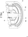
- FIG. 2 is a schematic cutaway view illustrating the speed reducer according to the first embodiment of the present disclosure.
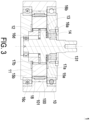
- FIG. 3 is a cross-sectional view illustrating the speed reducer according to the first embodiment of the present disclosure.
- FIG. 4 is a schematic front view illustrating the speed reducer according to the first embodiment of the present disclosure.
- the speed reducer 1 is a two-stage reducer.
- the speed reducer 1 includes an input shaft 10, an input gear 11, a fixing gear 12 and an output gear 13.
- the input shaft 10 is outer type defined by inputting manner and located at the outer side of the overall speed reducer 1.
- the input shaft 10 is outer type.
- the input shaft 10 is ring-shaped and has a first hollow structure.
- the input shaft 10 includes a ring-shaped inner wall 100 and a ring-shaped outer wall 101.
- the thicknesses between the ring-shaped inner wall 100 and the ring-shaped outer wall 101 are not the same so that an eccentricity is formed between the ring-shaped inner wall 100 and the ring-shaped outer wall 101 of the input shaft 10. That is, the eccentricity exists between the center of the ring-shaped inner wall 100 and the center of the ring-shaped outer wall 101.
- the input shaft 10 since the center of the ring-shaped inner wall 100 and the center of the ring-shaped outer wall 101 are eccentric, the input shaft 10 includes an eccentric structure formed by the ring-shaped inner wall 100 and the ring-shaped outer wall 101.
- the input gear 11 is accommodated within the first hollow structure of the input shaft 10 and disposed on the eccentric structure of the input shaft 10. While the input shaft 10 is rotated, the input gear 11 is rotated with the input shaft 10 and is eccentrically rotated about the center of the ring-shaped outer wall 101 of the input shaft 10.
- the input gear 11 includes a second hollow structure and a plurality of first teeth 110. Each of the plurality of first teeth 110 is surrounded and protruded from a ring-shaped inner wall of the input gear 11, and each of the plurality of first teeth 110 includes a first contact portion and a second contact portion arranged side by side in an axial direction. As shown in FIGS. 2 and 3 , the first teeth 110 are formed as the inner teeth on the ring-shaped inner wall of the input gear 11 corresponding to the input shaft 10 which is outer type.
- the fixing gear 12 is disposed corresponding to the input gear 11. Moreover, the fixing gear 12 is accommodated within the second hollow structure of the input gear 11 and disposed on the ring-shaped inner wall of the input gear 11.
- the fixing gear 12 is fixed and not rotatable.
- the fixing gear 12 includes a plurality of second teeth 120. Each of the plurality of second teeth 120 is surrounded and protruded from an outer periphery of the fixing gear 12 towarding to the input gear 11 and in contact with the corresponding first contact portion of the first tooth 110. Besides, the fixing gear 12 forms a first gear pair with the input gear 11.
- the output gear 13 is disposed corresponding to the input gear 11 and adjacent to the fixing gear 12. Moreover, the output gear 13 is accommodated within the second hollow structure of the input gear 11 and disposed on the ring-shaped inner wall of the input gear 11.
- the output gear 13 includes a plurality of third teeth 130. Each of the plurality of third teeth 130 is surrounded and protruded from an outer periphery of the output gear 13 towarding to the input gear 11 and in contact with the corresponding second contact portion of the first tooth 110. While the input gear 11 is rotated with the input shaft 10, the first teeth 110 are pushed against the corresponding third teeth 130. Consequently, the output gear 13 is correspondingly rotated.
- the output gear 13 forms a second gear pair with the input gear 11. Moreover, there is a first tooth number difference formed between the first teeth 110 and the second teeth 120. There is a second tooth number difference formed between the first teeth 110 and the third teeth 130. The first tooth number difference is different from the second tooth number difference.
- the fixing gear 12 and the output gear 13 of the speed reducer 1 share with the single input gear 11. Consequently, compared with the traditional speed reducer with two independent annular input gears, the speed reducer 1 not only has the high reduction ratio, but also has the advantages of less components, lower cost, a smaller volume and a stronger structural strength due to the use of the shared single input gear 11. Besides, the speed reducer 1 can avoid the problem about complicated machining the inner teeth since the use of the shared single input gear 11. Moreover, since the speed reducer 1 includes the fixing gear 12, so that the input gear 11 of the speed reducer 1 does not require the design of fixing holes or indexing holes as the traditional speed reducer. Consequently, the volume along a radial direction of the speed reducer 1 is reduced.
- the input shaft 10 is a power input terminal of the speed reducer 1, wherein a rotation speed of the input shaft 10 is defined as an input speed of the speed reducer 1.
- the output gear 13 is a power output terminal of the speed reducer 1, wherein a rotation speed of the output gear 13 is defined as an output speed of the speed reducer 1.
- S out is the output speed of the speed reducer 1
- S in is the input speed of the speed reducer 1
- TA is the number of the second teeth 120
- TB is the number of the third teeth 130
- TC is the number of the first teeth 110
- TCA is the first tooth number difference
- TCB is the second tooth number difference.
- the tooth number difference of any two of the first teeth 110, the second teeth 120 and the third teeth 130 is one to two teeth.
- the number of the first tooth number difference is one tooth
- the number of the second tooth number difference is two teeth.
- the tooth number difference of any two of the first teeth 110, the second teeth 120 and the third teeth 130 is two to four teeth.
- the number of the first tooth number difference is two teeth
- the output gear 13 further includes an output shaft 131 extending from a center of the output gear 13 to the two opposite outer sides. While the output gear 13 is rotated, the output shaft 131 is rotated with the output gear 13.
- the speed reducer 1 further includes a cover 14, a first fixing base 15a, a first ball bearing 16a, a first washer 17a, a second ball bearing 16b, a third ball bearing 16c, a needle bearing 18, a fourth ball bearing 16d, a second washer 17b and a second fixing base 15b.
- the first fixing base 15a and the second fixing base 15b are located at the opposite outer sides of the speed reducer 1 in the axial direction, wherein the fixing gear 12 is fixedly connected with the second fixing base 15b.
- the first fixing base 15a includes a third hollow structure
- the second fixing base 15b includes a fourth hollow structure.
- the cover 14 is disposed on the outer surface of the first fixing base 15a to cover one side of the third hollow structure.
- the first ball bearing 16a is disposed in the third hollow structure of the first fixing base 15a and arranged between the first fixing base 15a and the output shaft 131.
- the fourth ball bearing 16d is disposed in the fourth hollow structure of the second fixing base 15b and arranged between the second fixing base 15b and the output shaft 131.
- the output shaft 131 is rotatable within the third hollow structure of the first fixing base 15a and the fourth hollow structure of the second fixing base 15b through the first ball bearing 16a and the fourth ball bearing 16d.
- the second ball bearing 16b is disposed in the first hollow structure of the input shaft 10 and arranged between the first fixing base 15a and the input shaft 10.
- the third ball bearing 16c is disposed in the first hollow structure of the input shaft 10 and arranged between the second fixing base 15b and the input shaft 10.
- the first washer 17a is disposed between the first fixing base 15a and the input gear 11.
- the second washer 17b is disposed between the second fixing base 15b and the input gear 11.
- the needle bearing 18 is disposed in the first hollow structure of the input shaft 10 and arranged between the input gear 11 and the input shaft 10.
- the input shaft 10 is rotatable through the second ball bearing 16b, the third ball bearing 16c and the needle bearing 18.
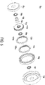
- FIG. 5 is a schematic exploded view illustrating a speed reducer according to a second embodiment of the present disclosure.
- FIG. 6 is a schematic cutaway view illustrating the speed reducer according to the second embodiment of the present disclosure.
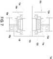
- FIG. 7 is a cross-sectional view illustrating a speed reducer according to a second embodiment of the present disclosure.
- FIG. 8 is a schematic front view illustrating the speed reducer according to the second embodiment of the present disclosure. Since the structure and the operation of the speed reducer 1a of this embodiment are similar to those of the first embodiment, the following description only uses the cross-sectional view shown in FIG. 5 to explain the speed reducer 1a.
- the speed reducer 1a is a two-stage reducer.
- the speed reducer 1a includes an input shaft 10a, an input gear 11a, a fixing gear 12a and an output gear 13a.
- the input shaft 10a is central type defined by inputting manner and located at a center of the overall speed reducer 1a.
- the input shaft 10a includes an eccentric structure 10b.
- the eccentric structure 10b is eccentrically fixed on the input shaft 10a. While the input shaft 10a is rotated, the eccentric structure 10b is rotated with the input shaft 10a and eccentrically rotated about the axle center of the input shaft 10a.
- the input gear 11a includes a first hollow structure, a ring-shaped inner wall, a ring-shaped outer wall and a plurality of first teeth 110a.
- the eccentric structure 10b is disposed in the first hollow structure. Consequently, while the eccentric structure 10b is rotated with the input shaft 10a, the input gear 11a is rotated with the eccentric structure 10b.
- the plurality of first teeth 110a are surrounded and protruded from the ring-shaped outer wall of the input gear 11a, and each of the plurality of first teeth 110a includes a first contact portion and a second contact portion arranged side by side in an axial direction.
- the first teeth 110a are formed as the outer teeth on the ring-shaped outer wall of the input gear 11a corresponding to the input shaft 10a which is central type.
- the fixing gear 12a is disposed corresponding to the input gear 11a and includes a second hollow structure. Moreover, the fixing gear 12a is disposed on the ring-shaped outer wall of the input gear 11a so that one part of the input gear 11a is accommodated within the second hollow structure of the fixing gear 12a.
- the fixing gear 12a is fixed and not rotatable.
- the fixing gear 12a includes a plurality of second teeth 120a. Each of the plurality of second teeth 120a is surrounded and protruded from an inner periphery of the fixing gear 12a towarding to the input gear 11a and in contact with the corresponding first contact portion of the first tooth 110a. Besides, the fixing gear 12a forms a first gear pair with the input gear 11a.
- the output gear 13a is disposed corresponding to the input gear 11a and adjacent to the fixing gear 12a, and the output gear 13a includes a third hollow structure. Moreover, the output gear 13a is disposed on the ring-shaped outer wall of the input gear 11a so that another part of the input gear 11a is accommodated within the third hollow structure of the output gear 13a.
- the output gear 13a includes a plurality of third teeth 130a. Each of the plurality of third teeth 130a is surrounded and protruded from an inner periphery of the output gear 13a towarding to the input gear 11a and in contact with the corresponding second contact portion of the first tooth 110a.
- the output gear 13a forms a second gear pair with the input gear 11a.
- the fixing gear 12a and the output gear 13a of the speed reducer 1a share with the single input gear 11a. Consequently, compared with the traditional speed reducer with two independent annular gears, the speed reducer 1a not only has the high reduction ratio, but also has the advantages of less components, lower cost, a smaller volume and a stronger structural strength due to the use of the shared single input gear 11a. Besides, since the speed reducer 1a includes the fixing gear 12a and the input gear 13a, the speed reducer 1a does not require the design of fixing holes or indexing holes as the traditional speed reducer. Consequently, the volume along a radial direction of the speed reducer 1a is reduced.
- the input shaft 10a is a power input terminal of the speed reducer 1a
- the output gear 13a is a power output terminal of the speed reducer 1a
- a rotation speed of the input shaft 10a is defined as an input speed of the speed reducer 1a
- a rotation speed of the output gear 13a is defined as an output speed of the speed reducer 1a
- S out is the output speed of the speed reducer 1a
- S in is the input speed of the speed reducer 1a
- TA is the number of the second teeth 120a
- TB is the number of the third teeth 130a
- TC is the number of the first teeth 110a
- TCA is the first tooth number difference
- TCB is the second tooth number difference.
- the tooth number difference of any two of the first teeth 110a, the second teeth 120a and the third teeth 130a is one to two teeth.
- the number of the first tooth number difference is one tooth
- the number of the second tooth number difference is two teeth.
- the tooth number difference of any two of the first teeth 110a, the second teeth 120a and the third teeth 130a is two to four teeth.
- the number of the first tooth number difference is two teeth
- the speed reducer 1a further includes a fixing base 15c, a first ball bearing 16e, a second ball bearing 16f, a third ball bearing 16g, a needle bearing 18a and an output disc 15d.
- the fixing base 15c and the output disc 15d are located at the opposite outer sides of the speed reducer 1a in the axial direction, wherein the fixing gear 12a is fixedly connected with the fixing base 15c, and the output gear 13a is connected with the output disc 15d. While the output gear 13a is rotated, the output disc 15d is rotated with the output gear 13a.
- the fixing base 15c includes a fourth hollow structure, and the output disc 15d includes a fifth hollow structure.
- the input shaft 10a is penetrated through the fourth hollow structure of the fixing base 15c, and another part of the input shaft 10a is penetrated through the fifth hollow structure of the output disc 15d.
- the first ball bearing 16e is disposed in the fourth hollow structure of the fixing base 15c and arranged between the fixing base 15c and the input shaft 10a.
- the second ball bearing 16f is disposed in the fifth hollow structure of the output disc 15d and arranged between the output disc 15d and the input shaft 10a.
- the input shaft 10a is rotatable within the fourth hollow structure of the fixing base 15c and the fifth hollow structure of the output disc 15d through the first ball bearing 16e and the second ball bearing 16f.
- the third ball bearing 16g is arranged between the fixing base 15c and the output disc 15d.
- the output disc 15d is rotatable through the third ball bearing 16g.
- the needle bearing 18a is disposed in the first hollow structure of the input gear 11a and arranged between the input gear 11a and the eccentric structure 10b.
- the input gear 11a is rotatable through the needle bearing 18a.
- the present disclosure provides a speed reducer.
- the fixing gear and the output gear of the speed reducer share with the single input gear. Consequently, compared with the traditional speed reducer with two independent annular input gears, the speed reducer not only has the high reduction ratio, but also has the advantages of less components, lower cost, a smaller volume and a stronger structural strength due to the use of the shared single input gear.
- the speed reducer since the speed reducer includes the fixing gear, the input gear of the speed reducer does not require the design of fixing holes or indexing holes as the traditional speed reducer. Consequently, the volume along a radial direction of the speed reducer is reduced.
Landscapes
- Engineering & Computer Science (AREA)
- General Engineering & Computer Science (AREA)
- Mechanical Engineering (AREA)
- Retarders (AREA)
- Valve Device For Special Equipments (AREA)
- Soil Working Implements (AREA)
Abstract
Description
- The present disclosure relates to a speed reducer, and more particularly to a speed reducer comprising an input gear shared by a fixing gear and an output gear.
- Generally, a motor is operated at a high speed and a low torque. In other words, it is difficult for the motor to drive a large-sized load. Consequently, for allowing the motor to drive a heavy object, a speed reducer is used for reducing the rotating speed of the motor and increasing the torque.
- In order to have a high reduction ratio, the structure of the speed reducer is usually complicated. Therefore, how to effectively improve the utilization of space of the speed reducer, and to maintain a high reduction ratio while reducing the number of the structural elements and the volume of the speed reducer is the focus of the design currently.
- The traditional speed reducer usually includes two independent annular input gears so that the speed reducer can achieve a high reduction ratio through the cooperation between the two annular input gears and other components of the speed reducer. However, due to the use of two annular input gears, the traditional speed reducer has the disadvantages of more components, more cost, a larger volume and a poor structural strength.
- Therefore, there is a need of providing an improved speed reducer in order to the overcome the above issues.
- An object of the present disclosure provides a speed reducer. Since the speed reducer includes a shared input gear, the speed reducer has the advantages of a high reduction ratio, less components, a smaller volume and a stronger structural strength.
- In accordance with an aspect of the present disclosure, a speed reducer is provided. The speed reducer includes an outer or a central type of input shaft, an input gear, a fixing gear and an output gear. The input shaft comprises an eccentric structure. The input gear is disposed on the eccentric structure of the input shaft, wherein the input gear is rotated with the input shaft and eccentrically rotated about an axel center of the input shaft, wherein the input gear comprises a plurality of first teeth, each of the plurality of first teeth comprises a first contact portion and a second contact portion arranged side by side in an axial direction. The fixing gear is disposed fixedly corresponding to the input gear and forming a first gear pair with the input gear, wherein the fixing gear comprises a plurality of second teeth, and each of the plurality of second teeth is in contact with the corresponding first contact portion of the first tooth. The output gear is disposed corresponding to the input gear and adjacent to the fixing gear and forming a second gear pair with the input gear, wherein the output gear comprises a plurality of third teeth, and each of the plurality of third teeth is in contact with the corresponding second contact portion of the first tooth, wherein while the input gear is rotated with the input shaft, the first teeth are pushed against the corresponding third teeth so that the output gear is correspondingly rotated. A first tooth number difference between the first teeth and the second teeth is different from a second tooth number difference between the first teeth and the third teeth.
- The above contents of the present disclosure will become more readily apparent to those ordinarily skilled in the art after reviewing the following detailed description and accompanying drawings, in which:
-
-
FIG. 1 is a schematic exploded view illustrating a speed reducer according to a first embodiment of the present disclosure; -
FIG. 2 is a schematic cutaway view illustrating the speed reducer according to the first embodiment of the present disclosure; -
FIG. 3 is a cross-sectional view illustrating the speed reducer according to the first embodiment of the present disclosure; -
FIG. 4 is a schematic front view illustrating the speed reducer according to the first embodiment of the present disclosure; -
FIG. 5 is a schematic exploded view illustrating a speed reducer according to a second embodiment of the present disclosure; -
FIG. 6 is a schematic cutaway view illustrating the speed reducer according to the second embodiment of the present disclosure; -
FIG. 7 is a cross-sectional view illustrating a speed reducer according to the second embodiment of the present disclosure; and -
FIG. 8 is a schematic front view illustrating the speed reducer according to the second embodiment of the present disclosure. - The present disclosure will now be described more specifically with reference to the following embodiments. It is to be noted that the following descriptions of preferred embodiments of this disclosure are presented herein for purpose of illustration and description only. It is not intended to be exhaustive or to be limited to the precise form disclosed.
- Please refer to
FIGS. 1 ,2 ,3 and4 .FIG. 1 is a schematic exploded view illustrating a speed reducer according to a first embodiment of the present disclosure.FIG. 2 is a schematic cutaway view illustrating the speed reducer according to the first embodiment of the present disclosure.FIG. 3 is a cross-sectional view illustrating the speed reducer according to the first embodiment of the present disclosure.FIG. 4 is a schematic front view illustrating the speed reducer according to the first embodiment of the present disclosure. In this embodiment, thespeed reducer 1 is a two-stage reducer. Thespeed reducer 1 includes aninput shaft 10, aninput gear 11, afixing gear 12 and anoutput gear 13. Theinput shaft 10 is outer type defined by inputting manner and located at the outer side of theoverall speed reducer 1. As shown inFIGS. 2 and3 , theinput shaft 10 is outer type. Theinput shaft 10 is ring-shaped and has a first hollow structure. Theinput shaft 10 includes a ring-shapedinner wall 100 and a ring-shapedouter wall 101. The thicknesses between the ring-shapedinner wall 100 and the ring-shapedouter wall 101 are not the same so that an eccentricity is formed between the ring-shapedinner wall 100 and the ring-shapedouter wall 101 of theinput shaft 10. That is, the eccentricity exists between the center of the ring-shapedinner wall 100 and the center of the ring-shapedouter wall 101. Moreover, since the center of the ring-shapedinner wall 100 and the center of the ring-shapedouter wall 101 are eccentric, theinput shaft 10 includes an eccentric structure formed by the ring-shapedinner wall 100 and the ring-shapedouter wall 101. - The
input gear 11 is accommodated within the first hollow structure of theinput shaft 10 and disposed on the eccentric structure of theinput shaft 10. While theinput shaft 10 is rotated, theinput gear 11 is rotated with theinput shaft 10 and is eccentrically rotated about the center of the ring-shapedouter wall 101 of theinput shaft 10. Theinput gear 11 includes a second hollow structure and a plurality offirst teeth 110. Each of the plurality offirst teeth 110 is surrounded and protruded from a ring-shaped inner wall of theinput gear 11, and each of the plurality offirst teeth 110 includes a first contact portion and a second contact portion arranged side by side in an axial direction. As shown inFIGS. 2 and3 , thefirst teeth 110 are formed as the inner teeth on the ring-shaped inner wall of theinput gear 11 corresponding to theinput shaft 10 which is outer type. - The
fixing gear 12 is disposed corresponding to theinput gear 11. Moreover, thefixing gear 12 is accommodated within the second hollow structure of theinput gear 11 and disposed on the ring-shaped inner wall of theinput gear 11. Thefixing gear 12 is fixed and not rotatable. Thefixing gear 12 includes a plurality ofsecond teeth 120. Each of the plurality ofsecond teeth 120 is surrounded and protruded from an outer periphery of thefixing gear 12 towarding to theinput gear 11 and in contact with the corresponding first contact portion of thefirst tooth 110. Besides, thefixing gear 12 forms a first gear pair with theinput gear 11. - The
output gear 13 is disposed corresponding to theinput gear 11 and adjacent to thefixing gear 12. Moreover, theoutput gear 13 is accommodated within the second hollow structure of theinput gear 11 and disposed on the ring-shaped inner wall of theinput gear 11. Theoutput gear 13 includes a plurality ofthird teeth 130. Each of the plurality ofthird teeth 130 is surrounded and protruded from an outer periphery of theoutput gear 13 towarding to theinput gear 11 and in contact with the corresponding second contact portion of thefirst tooth 110. While theinput gear 11 is rotated with theinput shaft 10, thefirst teeth 110 are pushed against the correspondingthird teeth 130. Consequently, theoutput gear 13 is correspondingly rotated. Besides, theoutput gear 13 forms a second gear pair with theinput gear 11. Moreover, there is a first tooth number difference formed between thefirst teeth 110 and thesecond teeth 120. There is a second tooth number difference formed between thefirst teeth 110 and thethird teeth 130. The first tooth number difference is different from the second tooth number difference. - In accordance with the present disclosure, the fixing
gear 12 and theoutput gear 13 of thespeed reducer 1 share with thesingle input gear 11. Consequently, compared with the traditional speed reducer with two independent annular input gears, thespeed reducer 1 not only has the high reduction ratio, but also has the advantages of less components, lower cost, a smaller volume and a stronger structural strength due to the use of the sharedsingle input gear 11. Besides, thespeed reducer 1 can avoid the problem about complicated machining the inner teeth since the use of the sharedsingle input gear 11. Moreover, since thespeed reducer 1 includes the fixinggear 12, so that theinput gear 11 of thespeed reducer 1 does not require the design of fixing holes or indexing holes as the traditional speed reducer. Consequently, the volume along a radial direction of thespeed reducer 1 is reduced. - In this embodiment, the
input shaft 10 is a power input terminal of thespeed reducer 1, wherein a rotation speed of theinput shaft 10 is defined as an input speed of thespeed reducer 1. Theoutput gear 13 is a power output terminal of thespeed reducer 1, wherein a rotation speed of theoutput gear 13 is defined as an output speed of thespeed reducer 1. Besides, the reduction ratio of thespeed reducer 1 is equal to a ratio calculated by dividing the number of teeth on the larger gear by the number of teeth on the smaller gear, and can be expressed as the following formulas:

- Wherein Sout is the output speed of the
speed reducer 1, Sin is the input speed of thespeed reducer 1, TA is the number of thesecond teeth 120, TB is the number of thethird teeth 130, TC is the number of thefirst teeth 110, TCA is the first tooth number difference and TCB is the second tooth number difference. The tooth number difference of any two of thefirst teeth 110, thesecond teeth 120 and thethird teeth 130 is one to two teeth. For example, the number of the first tooth number difference is one tooth, and the number of the second tooth number difference is two teeth. - In case that the number of the second teeth 120 (TA) is 31 teeth, the number of the third teeth 130 (TB) is 30 teeth and the number of the first teeth 110 (TC) is 32 teeth, according to the above formula, TA1=31/1=31, TB1=30/2=15, TC1=32/1=32, TC2=32/2=16. Therefore,

input shaft 10 and theoutput gear 13 rotate in opposite directions. - In some embodiments, the tooth number difference of any two of the
first teeth 110, thesecond teeth 120 and thethird teeth 130 is two to four teeth. For example, the number of the first tooth number difference is two teeth, and the number of the second tooth number difference is four teeth. Therefore, in case that the number of the second teeth 120 (TA) is 70 teeth, the number of the third teeth 130 (TB) is 68 teeth and the number of the first teeth 110 (TC) is 72 teeth, the number of the first tooth number difference is two teeth, and the number of the second tooth number difference is four teeth, and according to the above formula, TA1=70/2=35, TB1 =68/4=17, TC1=72/2=36, TC2=72/4=18. Therefore, Sout = Sin ×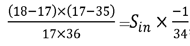
input shaft 10 and theoutput gear 13 rotate in opposite directions. - In some embodiments, the
output gear 13 further includes anoutput shaft 131 extending from a center of theoutput gear 13 to the two opposite outer sides. While theoutput gear 13 is rotated, theoutput shaft 131 is rotated with theoutput gear 13. - In some embodiments, the
speed reducer 1 further includes acover 14, afirst fixing base 15a, afirst ball bearing 16a, afirst washer 17a, a second ball bearing 16b, athird ball bearing 16c, aneedle bearing 18, afourth ball bearing 16d, asecond washer 17b and asecond fixing base 15b. Thefirst fixing base 15a and thesecond fixing base 15b are located at the opposite outer sides of thespeed reducer 1 in the axial direction, wherein the fixinggear 12 is fixedly connected with thesecond fixing base 15b. Thefirst fixing base 15a includes a third hollow structure, and thesecond fixing base 15b includes a fourth hollow structure. One part of theoutput shaft 131 is penetrated through the third hollow structure of thefirst fixing base 15a, and another part of theoutput shaft 131 is penetrated through the fourth hollow structure of thesecond fixing base 15b. Thecover 14 is disposed on the outer surface of thefirst fixing base 15a to cover one side of the third hollow structure. Thefirst ball bearing 16a is disposed in the third hollow structure of thefirst fixing base 15a and arranged between thefirst fixing base 15a and theoutput shaft 131. Thefourth ball bearing 16d is disposed in the fourth hollow structure of thesecond fixing base 15b and arranged between thesecond fixing base 15b and theoutput shaft 131. Theoutput shaft 131 is rotatable within the third hollow structure of thefirst fixing base 15a and the fourth hollow structure of thesecond fixing base 15b through thefirst ball bearing 16a and thefourth ball bearing 16d. Thesecond ball bearing 16b is disposed in the first hollow structure of theinput shaft 10 and arranged between thefirst fixing base 15a and theinput shaft 10. Thethird ball bearing 16c is disposed in the first hollow structure of theinput shaft 10 and arranged between thesecond fixing base 15b and theinput shaft 10. Thefirst washer 17a is disposed between thefirst fixing base 15a and theinput gear 11. Thesecond washer 17b is disposed between thesecond fixing base 15b and theinput gear 11. Theneedle bearing 18 is disposed in the first hollow structure of theinput shaft 10 and arranged between theinput gear 11 and theinput shaft 10. Theinput shaft 10 is rotatable through the second ball bearing 16b, thethird ball bearing 16c and theneedle bearing 18. - Please refer to
FIGs. 5 ,6 ,7 and8 .FIG. 5 is a schematic exploded view illustrating a speed reducer according to a second embodiment of the present disclosure.FIG. 6 is a schematic cutaway view illustrating the speed reducer according to the second embodiment of the present disclosure.FIG. 7 is a cross-sectional view illustrating a speed reducer according to a second embodiment of the present disclosure.FIG. 8 is a schematic front view illustrating the speed reducer according to the second embodiment of the present disclosure. Since the structure and the operation of thespeed reducer 1a of this embodiment are similar to those of the first embodiment, the following description only uses the cross-sectional view shown inFIG. 5 to explain thespeed reducer 1a. Thespeed reducer 1a is a two-stage reducer. Thespeed reducer 1a includes aninput shaft 10a, aninput gear 11a, afixing gear 12a and anoutput gear 13a. Theinput shaft 10a is central type defined by inputting manner and located at a center of theoverall speed reducer 1a. Theinput shaft 10a includes aneccentric structure 10b. Theeccentric structure 10b is eccentrically fixed on theinput shaft 10a. While theinput shaft 10a is rotated, theeccentric structure 10b is rotated with theinput shaft 10a and eccentrically rotated about the axle center of theinput shaft 10a. - The
input gear 11a includes a first hollow structure, a ring-shaped inner wall, a ring-shaped outer wall and a plurality offirst teeth 110a. Theeccentric structure 10b is disposed in the first hollow structure. Consequently, while theeccentric structure 10b is rotated with theinput shaft 10a, theinput gear 11a is rotated with theeccentric structure 10b. The plurality offirst teeth 110a are surrounded and protruded from the ring-shaped outer wall of theinput gear 11a, and each of the plurality offirst teeth 110a includes a first contact portion and a second contact portion arranged side by side in an axial direction. Besides, thefirst teeth 110a are formed as the outer teeth on the ring-shaped outer wall of theinput gear 11a corresponding to theinput shaft 10a which is central type. - The
fixing gear 12a is disposed corresponding to theinput gear 11a and includes a second hollow structure. Moreover, thefixing gear 12a is disposed on the ring-shaped outer wall of theinput gear 11a so that one part of theinput gear 11a is accommodated within the second hollow structure of thefixing gear 12a. Thefixing gear 12a is fixed and not rotatable. Thefixing gear 12a includes a plurality ofsecond teeth 120a. Each of the plurality ofsecond teeth 120a is surrounded and protruded from an inner periphery of thefixing gear 12a towarding to theinput gear 11a and in contact with the corresponding first contact portion of thefirst tooth 110a. Besides, thefixing gear 12a forms a first gear pair with theinput gear 11a. - The
output gear 13a is disposed corresponding to theinput gear 11a and adjacent to thefixing gear 12a, and theoutput gear 13a includes a third hollow structure. Moreover, theoutput gear 13a is disposed on the ring-shaped outer wall of theinput gear 11a so that another part of theinput gear 11a is accommodated within the third hollow structure of theoutput gear 13a. Theoutput gear 13a includes a plurality ofthird teeth 130a. Each of the plurality ofthird teeth 130a is surrounded and protruded from an inner periphery of theoutput gear 13a towarding to theinput gear 11a and in contact with the corresponding second contact portion of thefirst tooth 110a. While theinput gear 11a is rotated with theinput shaft 10a, thefirst teeth 110a are pushed against the correspondingthird teeth 130a. Consequently, theoutput gear 13a is correspondingly rotated. Besides, theoutput gear 13a forms a second gear pair with theinput gear 11a. Moreover, there is a first tooth number difference formed between thefirst teeth 110a and thesecond teeth 120a. There is a second tooth number difference formed between thefirst teeth 110a and thethird teeth 130a. The first tooth number difference is different from the second tooth number difference. - In accordance with the present disclosure, the
fixing gear 12a and theoutput gear 13a of thespeed reducer 1a share with thesingle input gear 11a. Consequently, compared with the traditional speed reducer with two independent annular gears, thespeed reducer 1a not only has the high reduction ratio, but also has the advantages of less components, lower cost, a smaller volume and a stronger structural strength due to the use of the sharedsingle input gear 11a. Besides, since thespeed reducer 1a includes thefixing gear 12a and theinput gear 13a, thespeed reducer 1a does not require the design of fixing holes or indexing holes as the traditional speed reducer. Consequently, the volume along a radial direction of thespeed reducer 1a is reduced. - In this embodiment, the
input shaft 10a is a power input terminal of thespeed reducer 1a, and theoutput gear 13a is a power output terminal of thespeed reducer 1a. Wherein a rotation speed of theinput shaft 10a is defined as an input speed of thespeed reducer 1a, and a rotation speed of theoutput gear 13a is defined as an output speed of thespeed reducer 1a. Besides, the reduction ratio of thespeed reducer 1 is equal to the following formula:

- Wherein Sout is the output speed of the
speed reducer 1a, Sin is the input speed of thespeed reducer 1a, TA is the number of thesecond teeth 120a, TB is the number of thethird teeth 130a, TC is the number of thefirst teeth 110a, TCA is the first tooth number difference, and TCB is the second tooth number difference. The tooth number difference of any two of thefirst teeth 110a, thesecond teeth 120a and thethird teeth 130a is one to two teeth. For example, the number of the first tooth number difference is one tooth, and the number of the second tooth number difference is two teeth. - In case that the number of the
second teeth 120a (TA) is 31 teeth, the number of thethird teeth 130a (TB) is 32 teeth and the number of thefirst teeth 110a (TC) is 30 teeth, according to the above formula, TA1=31/1=31, TB1=32/2=16, TC1=30/1=30, TC2=30/2=15. Therefore,
- In some embodiments, the tooth number difference of any two of the
first teeth 110a, thesecond teeth 120a and thethird teeth 130a is two to four teeth. For example, the number of the first tooth number difference is two teeth, and the number of the second tooth number difference is four teeth. Therefore, in case that the number of thesecond teeth 120a (TA) is 68 teeth, the number of thethird teeth 130a (TB) is 70 teeth and the number of thefirst teeth 130a (TC) is 72 teeth, according to the above formula, TA1=68/4=17, TB1=70/2=35, TC1=72/4=18, TC2=72/2=36. Therefore,
- In some embodiments, the
speed reducer 1a further includes a fixingbase 15c, afirst ball bearing 16e, a second ball bearing 16f, athird ball bearing 16g, aneedle bearing 18a and anoutput disc 15d. The fixingbase 15c and theoutput disc 15d are located at the opposite outer sides of thespeed reducer 1a in the axial direction, wherein thefixing gear 12a is fixedly connected with the fixingbase 15c, and theoutput gear 13a is connected with theoutput disc 15d. While theoutput gear 13a is rotated, theoutput disc 15d is rotated with theoutput gear 13a. The fixingbase 15c includes a fourth hollow structure, and theoutput disc 15d includes a fifth hollow structure. One part of theinput shaft 10a is penetrated through the fourth hollow structure of the fixingbase 15c, and another part of theinput shaft 10a is penetrated through the fifth hollow structure of theoutput disc 15d. Thefirst ball bearing 16e is disposed in the fourth hollow structure of the fixingbase 15c and arranged between the fixingbase 15c and theinput shaft 10a. The second ball bearing 16f is disposed in the fifth hollow structure of theoutput disc 15d and arranged between theoutput disc 15d and theinput shaft 10a. Theinput shaft 10a is rotatable within the fourth hollow structure of the fixingbase 15c and the fifth hollow structure of theoutput disc 15d through thefirst ball bearing 16e and the second ball bearing 16f. Thethird ball bearing 16g is arranged between the fixingbase 15c and theoutput disc 15d. Theoutput disc 15d is rotatable through thethird ball bearing 16g. Theneedle bearing 18a is disposed in the first hollow structure of theinput gear 11a and arranged between theinput gear 11a and theeccentric structure 10b. Theinput gear 11a is rotatable through theneedle bearing 18a. - From the above descriptions, the present disclosure provides a speed reducer. The fixing gear and the output gear of the speed reducer share with the single input gear. Consequently, compared with the traditional speed reducer with two independent annular input gears, the speed reducer not only has the high reduction ratio, but also has the advantages of less components, lower cost, a smaller volume and a stronger structural strength due to the use of the shared single input gear. Moreover, since the speed reducer includes the fixing gear, the input gear of the speed reducer does not require the design of fixing holes or indexing holes as the traditional speed reducer. Consequently, the volume along a radial direction of the speed reducer is reduced.
Claims (10)
- A speed reducer (1, 1a), characterized by comprising:an outer or a central type of input shaft (10, 10a), wherein the input shaft (10, 10a) comprises an eccentric structure (10b);an input gear (11, 11a) disposed on the eccentric structure (10b) of the input shaft (10, 10a), wherein the input gear (11, 11a) is rotated with the input shaft (10, 10a) and eccentrically rotated about an axel center of the input shaft (10, 10a), wherein the input gear (10, 10a) comprises a plurality of first teeth (110, 110a), each of the plurality of first teeth (110, 110a) comprises a first contact portion and a second contact portion arranged side by side in an axial direction;a fixing gear (12, 12a) disposed fixedly corresponding to the input gear (10, 10a) and forming a first gear pair with the input gear (10, 10a), wherein the fixing gear (12, 12a) comprises a plurality of second teeth (120, 120a), and each of the plurality of second teeth (120, 120a) is in contact with the corresponding first contact portion of the first tooth (110, 110a); andan output gear (13, 13a) disposed corresponding to the input gear (11, 11a) and adjacent to the fixing gear (12, 12a) and forming a second gear pair with the input gear (11, 11a), wherein the output gear (13, 13a) comprises a plurality of third teeth (130, 130a), and each of the plurality of third teeth (130, 130a) is in contact with the corresponding second contact portion of the first tooth (110, 110a), wherein while the input gear (11, 11a) is rotated with the input shaft (10, 10a), the first teeth (110, 110a) are pushed against the corresponding third teeth (130, 130a), so that the output gear (13, 13a) is correspondingly rotated;wherein a first tooth number difference between the first teeth (110, 110a) and the second teeth (120, 120a) is different from a second tooth number difference between the first teeth (110, 110a) and the third teeth (130, 130a).
- The speed reducer (1, 1a) according to claim 1, wherein the input shaft (10) is outer type, and the plurality of first teeth (110) are formed as the inner teeth, wherein a reduction ratio of the speed reducer (1) is equal to the following formula:


- The speed reducer (1, 1a) according to claim 2, wherein the input shaft (10) comprises a ring-shaped inner wall (100) and a ring-shaped outer wall (101), wherein an eccentricity is formed between the ring-shaped inner wall (100) and the ring-shaped outer wall (101), so that forms the eccentric structure, and wherein the input gear (11) is accommodated within the input shaft (10), wherein each of the plurality of first teeth (110) is surrounded and protruded from a ring-shaped inner wall of the input gear (11).
- The speed reducer (1, 1a) according to claim 3, wherein the fixing gear (12) is accommodated within the input gear (11) and disposed on the ring-shaped inner wall of the input gear (11), wherein each of the plurality of second teeth (120) is surrounded and protruded from an outer periphery of the fixing gear (12).
- The speed reducer (1, 1a) according to claim 4, wherein the output gear (13) is accommodated within the input gear (11) and disposed on the ring-shaped inner wall of the input gear (11), wherein each of the plurality of third teeth (130) is surrounded and protruded from an outer periphery of the output gear (13).
- The speed reducer (1, 1a) according to claim 1, wherein the input shaft (10a) is central type, and the plurality of first teeth (110a) are formed as the outer teeth, wherein a reduction ratio of the speed reducer (1a) is equal to the following formula:


- The speed reducer (1, 1a) according to claim 6, wherein the eccentric structure (10b) is eccentrically fixed on the input shaft (10a), wherein the eccentric structure (10b) is rotated with the input shaft (10a) and eccentrically rotated about the axle center of the input shaft (10a).
- The speed reducer (1, 1a) according to claim 7, wherein the input gear (11a) comprises a ring-shaped outer wall, wherein the eccentric structure (10b) is disposed within the input gear (11a), and the plurality of first teeth (110a) are surrounded and protruded from the ring-shaped outer wall.
- The speed reducer (1, 1a) according to claim 8, wherein the fixing gear (12a) is disposed on the ring-shaped outer wall of the input gear (11a), so that the input gear (11a) is accommodated within the fixing gear (12a), wherein each of the plurality of second teeth (120a) is surrounded and protruded from an inner periphery of the fixing gear (12a).
- The speed reducer (1, 1a) according to claim 9, wherein the output gear (13a) is disposed on the ring-shaped outer wall of the input gear (11a), so that the input gear (11a) is accommodated within the output gear (13a), wherein each of the plurality of third teeth (130a) is surrounded and protruded from an inner periphery of the output gear (13a).
Applications Claiming Priority (2)
| Application Number | Priority Date | Filing Date | Title |
|---|---|---|---|
| US202163247967P | 2021-09-24 | 2021-09-24 | |
| US17/731,074 US12060923B2 (en) | 2021-09-24 | 2022-04-27 | Speed reducer |
Publications (1)
| Publication Number | Publication Date |
|---|---|
| EP4155577A1 true EP4155577A1 (en) | 2023-03-29 |
Family
ID=82898790
Family Applications (1)
| Application Number | Title | Priority Date | Filing Date |
|---|---|---|---|
| EP22190020.2A Pending EP4155577A1 (en) | 2021-09-24 | 2022-08-11 | Speed reducer |
Country Status (4)
| Country | Link |
|---|---|
| US (1) | US12060923B2 (en) |
| EP (1) | EP4155577A1 (en) |
| CN (1) | CN115853968A (en) |
| TW (1) | TWI814439B (en) |
Citations (3)
| Publication number | Priority date | Publication date | Assignee | Title |
|---|---|---|---|---|
| DE3131612A1 (en) * | 1981-08-10 | 1983-02-24 | Zahnräderfabrik Renk AG, 8900 Augsburg | GEARBOX FOR POSITIONING SOLAR ENERGY COLLECTORS |
| DE102020104758A1 (en) * | 2019-02-25 | 2020-08-27 | Sumitomo Heavy Industries, Ltd. | REDUCTION GEAR |
| DE102020134973A1 (en) * | 2020-02-04 | 2021-08-05 | Sumitomo Heavy Industries, Ltd. | GEAR DEVICE OF THE BENDING ENGAGEMENT TYPE |
Family Cites Families (17)
| Publication number | Priority date | Publication date | Assignee | Title |
|---|---|---|---|---|
| US2250259A (en) * | 1940-03-11 | 1941-07-22 | Jr Bradford Foote | Speed reducing gearing |
| US3377886A (en) * | 1966-08-02 | 1968-04-16 | Atomic Energy Commission Usa | Speed reducer |
| US3558944A (en) * | 1969-02-03 | 1971-01-26 | Bendix Corp | Self-commutated actuator |
| CN2534423Y (en) | 2002-04-24 | 2003-02-05 | 李有宏 | Profile shifted gear speed reducer |
| CN103307216A (en) | 2012-03-07 | 2013-09-18 | 庄聿翔 | Planetary speed difference reducer |
| CN103410924A (en) | 2013-04-19 | 2013-11-27 | 四川大学 | Intelligent reducer |
| CN204403286U (en) | 2015-01-16 | 2015-06-17 | 苏州悍猛谐波机电有限公司 | Synchronous cycloid reduction device |
| TWI548823B (en) | 2015-04-14 | 2016-09-11 | 台達電子工業股份有限公司 | Deceleration machine |
| KR101805576B1 (en) | 2016-09-01 | 2017-12-07 | 주식회사 세진아이지비 | Planetary reduction gear device for ultra high reduction gear ratio |
| EP3399211B1 (en) | 2017-05-03 | 2021-07-21 | Delta Electronics, Inc. | Cycloid speed reducer |
| CN208858869U (en) | 2018-07-06 | 2019-05-14 | 华南理工大学 | A kind of fewer differential teeth planetary line gear retarder |
| JP2020070823A (en) | 2018-10-29 | 2020-05-07 | 京セラドキュメントソリューションズ株式会社 | Speed reducer, developing device, and image forming device |
| CN111156294B (en) | 2018-11-07 | 2021-06-11 | 台达电子工业股份有限公司 | Speed reducer |
| US11336147B2 (en) | 2018-11-07 | 2022-05-17 | Delta Electronics, Inc. | Speed reducing device having power source |
| CN110360274A (en) | 2019-07-22 | 2019-10-22 | 孙金曦 | Planetary speed reducer with small tooth number difference |
| TWM591134U (en) | 2019-09-11 | 2020-02-21 | 國立虎尾科技大學 | Gear variable-speed mechanism |
| TWI704305B (en) | 2019-11-01 | 2020-09-11 | 上銀科技股份有限公司 | High reduction ratio reducer |
-
2022
- 2022-04-27 US US17/731,074 patent/US12060923B2/en active Active
- 2022-06-13 TW TW111121806A patent/TWI814439B/en active
- 2022-06-13 CN CN202210661863.8A patent/CN115853968A/en active Pending
- 2022-08-11 EP EP22190020.2A patent/EP4155577A1/en active Pending
Patent Citations (3)
| Publication number | Priority date | Publication date | Assignee | Title |
|---|---|---|---|---|
| DE3131612A1 (en) * | 1981-08-10 | 1983-02-24 | Zahnräderfabrik Renk AG, 8900 Augsburg | GEARBOX FOR POSITIONING SOLAR ENERGY COLLECTORS |
| DE102020104758A1 (en) * | 2019-02-25 | 2020-08-27 | Sumitomo Heavy Industries, Ltd. | REDUCTION GEAR |
| DE102020134973A1 (en) * | 2020-02-04 | 2021-08-05 | Sumitomo Heavy Industries, Ltd. | GEAR DEVICE OF THE BENDING ENGAGEMENT TYPE |
Also Published As
| Publication number | Publication date |
|---|---|
| TW202314143A (en) | 2023-04-01 |
| CN115853968A (en) | 2023-03-28 |
| US20230095283A1 (en) | 2023-03-30 |
| US12060923B2 (en) | 2024-08-13 |
| TWI814439B (en) | 2023-09-01 |
Similar Documents
| Publication | Publication Date | Title |
|---|---|---|
| JP6137875B2 (en) | Planetary gear reducer | |
| US12359711B2 (en) | Speed reducer | |
| US10520062B2 (en) | Cycloid speed reducer | |
| US11486469B2 (en) | Cycloid speed reducer | |
| EP4141287B1 (en) | Transmission mechanism | |
| US11336147B2 (en) | Speed reducing device having power source | |
| CN108953541B (en) | RV speed reducer with ultralow reduction ratio | |
| JPWO2008053775A1 (en) | Decelerator | |
| US11555531B1 (en) | Cycloid speed reducer | |
| JPS63254251A (en) | Planetary gear speed variation gear | |
| EP3081424B1 (en) | Speed reducer | |
| US12060923B2 (en) | Speed reducer | |
| US11572941B2 (en) | Wave generator for reducer of harmonic drive structure | |
| CN108757847B (en) | RV speed reducer with large reduction ratio | |
| CN113915295B (en) | Differential cycloidal pin gear speed reducer | |
| US11391347B2 (en) | Cycloid speed reducer with enhanced dynamic balance | |
| CN111156294B (en) | Speed reducer | |
| CN114110096A (en) | RV reduction gear, robot | |
| US12013013B2 (en) | Gear mechanism and gear | |
| US20250189012A1 (en) | Gear device and actuator | |
| CN121782335A (en) | High-transmission-ratio sine-tooth RV reducer | |
| KR20250051538A (en) | Cycloidal deducer | |
| KR20250051537A (en) | Cycloidal deducer | |
| KR20250051535A (en) | Cycloidal deducer | |
| KR20250051536A (en) | Cycloidal deducer |
Legal Events
| Date | Code | Title | Description |
|---|---|---|---|
| PUAI | Public reference made under article 153(3) epc to a published international application that has entered the european phase |
Free format text: ORIGINAL CODE: 0009012 |
|
| STAA | Information on the status of an ep patent application or granted ep patent |
Free format text: STATUS: THE APPLICATION HAS BEEN PUBLISHED |
|
| AK | Designated contracting states |
Kind code of ref document: A1 Designated state(s): AL AT BE BG CH CY CZ DE DK EE ES FI FR GB GR HR HU IE IS IT LI LT LU LV MC MK MT NL NO PL PT RO RS SE SI SK SM TR |
|
| STAA | Information on the status of an ep patent application or granted ep patent |
Free format text: STATUS: REQUEST FOR EXAMINATION WAS MADE |
|
| 17P | Request for examination filed |
Effective date: 20230719 |
|
| RBV | Designated contracting states (corrected) |
Designated state(s): AL AT BE BG CH CY CZ DE DK EE ES FI FR GB GR HR HU IE IS IT LI LT LU LV MC MK MT NL NO PL PT RO RS SE SI SK SM TR |
|
| STAA | Information on the status of an ep patent application or granted ep patent |
Free format text: STATUS: EXAMINATION IS IN PROGRESS |
|
| 17Q | First examination report despatched |
Effective date: 20241022 |
|
| GRAP | Despatch of communication of intention to grant a patent |
Free format text: ORIGINAL CODE: EPIDOSNIGR1 |
|
| STAA | Information on the status of an ep patent application or granted ep patent |
Free format text: STATUS: GRANT OF PATENT IS INTENDED |
|
| INTG | Intention to grant announced |
Effective date: 20251222 |
|
| GRAS | Grant fee paid |
Free format text: ORIGINAL CODE: EPIDOSNIGR3 |
|
| GRAJ | Information related to disapproval of communication of intention to grant by the applicant or resumption of examination proceedings by the epo deleted |
Free format text: ORIGINAL CODE: EPIDOSDIGR1 |
|
| GRAL | Information related to payment of fee for publishing/printing deleted |
Free format text: ORIGINAL CODE: EPIDOSDIGR3 |
|
| STAA | Information on the status of an ep patent application or granted ep patent |
Free format text: STATUS: EXAMINATION IS IN PROGRESS |
|
| INTC | Intention to grant announced (deleted) |