EP4155570A1 - Rotor clip for brake assembly - Google Patents
Rotor clip for brake assembly Download PDFInfo
- Publication number
- EP4155570A1 EP4155570A1 EP21461600.5A EP21461600A EP4155570A1 EP 4155570 A1 EP4155570 A1 EP 4155570A1 EP 21461600 A EP21461600 A EP 21461600A EP 4155570 A1 EP4155570 A1 EP 4155570A1
- Authority
- EP
- European Patent Office
- Prior art keywords
- sheet metal
- metal strip
- rotor
- body portion
- clip
- Prior art date
- Legal status (The legal status is an assumption and is not a legal conclusion. Google has not performed a legal analysis and makes no representation as to the accuracy of the status listed.)
- Granted
Links
Images


Classifications
-
- F—MECHANICAL ENGINEERING; LIGHTING; HEATING; WEAPONS; BLASTING
- F16—ENGINEERING ELEMENTS AND UNITS; GENERAL MEASURES FOR PRODUCING AND MAINTAINING EFFECTIVE FUNCTIONING OF MACHINES OR INSTALLATIONS; THERMAL INSULATION IN GENERAL
- F16D—COUPLINGS FOR TRANSMITTING ROTATION; CLUTCHES; BRAKES
- F16D65/00—Parts or details
- F16D65/02—Braking members; Mounting thereof
- F16D65/12—Discs; Drums for disc brakes
- F16D65/125—Discs; Drums for disc brakes characterised by the material used for the disc body
- F16D65/126—Discs; Drums for disc brakes characterised by the material used for the disc body the material being of low mechanical strength, e.g. carbon, beryllium; Torque transmitting members therefor
-
- B—PERFORMING OPERATIONS; TRANSPORTING
- B60—VEHICLES IN GENERAL
- B60B—VEHICLE WHEELS; CASTORS; AXLES FOR WHEELS OR CASTORS; INCREASING WHEEL ADHESION
- B60B27/00—Hubs
- B60B27/0047—Hubs characterised by functional integration of other elements
- B60B27/0052—Hubs characterised by functional integration of other elements the element being a brake disc
-
- B—PERFORMING OPERATIONS; TRANSPORTING
- B64—AIRCRAFT; AVIATION; COSMONAUTICS
- B64C—AEROPLANES; HELICOPTERS
- B64C25/00—Alighting gear
- B64C25/32—Alighting gear characterised by elements which contact the ground or similar surface
- B64C25/34—Alighting gear characterised by elements which contact the ground or similar surface wheeled type, e.g. multi-wheeled bogies
- B64C25/36—Arrangements or adaptations of wheels, tyres or axles in general
-
- F—MECHANICAL ENGINEERING; LIGHTING; HEATING; WEAPONS; BLASTING
- F16—ENGINEERING ELEMENTS AND UNITS; GENERAL MEASURES FOR PRODUCING AND MAINTAINING EFFECTIVE FUNCTIONING OF MACHINES OR INSTALLATIONS; THERMAL INSULATION IN GENERAL
- F16D—COUPLINGS FOR TRANSMITTING ROTATION; CLUTCHES; BRAKES
- F16D65/00—Parts or details
- F16D65/02—Braking members; Mounting thereof
- F16D65/12—Discs; Drums for disc brakes
- F16D65/123—Discs; Drums for disc brakes comprising an annular disc secured to a hub member; Discs characterised by means for mounting
-
- F—MECHANICAL ENGINEERING; LIGHTING; HEATING; WEAPONS; BLASTING
- F16—ENGINEERING ELEMENTS AND UNITS; GENERAL MEASURES FOR PRODUCING AND MAINTAINING EFFECTIVE FUNCTIONING OF MACHINES OR INSTALLATIONS; THERMAL INSULATION IN GENERAL
- F16D—COUPLINGS FOR TRANSMITTING ROTATION; CLUTCHES; BRAKES
- F16D65/00—Parts or details
- F16D65/02—Braking members; Mounting thereof
- F16D2065/13—Parts or details of discs or drums
- F16D2065/134—Connection
- F16D2065/1392—Connection elements
-
- F—MECHANICAL ENGINEERING; LIGHTING; HEATING; WEAPONS; BLASTING
- F16—ENGINEERING ELEMENTS AND UNITS; GENERAL MEASURES FOR PRODUCING AND MAINTAINING EFFECTIVE FUNCTIONING OF MACHINES OR INSTALLATIONS; THERMAL INSULATION IN GENERAL
- F16D—COUPLINGS FOR TRANSMITTING ROTATION; CLUTCHES; BRAKES
- F16D2250/00—Manufacturing; Assembly
- F16D2250/0084—Assembly or disassembly
-
- F—MECHANICAL ENGINEERING; LIGHTING; HEATING; WEAPONS; BLASTING
- F16—ENGINEERING ELEMENTS AND UNITS; GENERAL MEASURES FOR PRODUCING AND MAINTAINING EFFECTIVE FUNCTIONING OF MACHINES OR INSTALLATIONS; THERMAL INSULATION IN GENERAL
- F16D—COUPLINGS FOR TRANSMITTING ROTATION; CLUTCHES; BRAKES
- F16D55/00—Brakes with substantially-radial braking surfaces pressed together in axial direction, e.g. disc brakes
- F16D55/24—Brakes with substantially-radial braking surfaces pressed together in axial direction, e.g. disc brakes with a plurality of axially-movable discs, lamellae, or pads, pressed from one side towards an axially-located member
- F16D55/26—Brakes with substantially-radial braking surfaces pressed together in axial direction, e.g. disc brakes with a plurality of axially-movable discs, lamellae, or pads, pressed from one side towards an axially-located member without self-tightening action
- F16D55/36—Brakes with a plurality of rotating discs all lying side by side
Definitions
- the present disclosure relates to a clip for the rotor of a brake assembly.
- Braking assemblies for applying a braking force to a rotating body e.g. a wheel are well known and typically comprise a brake stack of alternating rotor and stator disks.
- the braking assembly is actuated by applying a force to an actuator e.g. a piston which applies force to a pressure plate which compresses the rotor and stator disks of the brake stack together to cause deceleration and braking by friction.
- an actuator e.g. a piston which applies force to a pressure plate which compresses the rotor and stator disks of the brake stack together to cause deceleration and braking by friction.
- the rotor disks are provided with circumferential drive lugs via which the compressive force is applied to the rotor disks.
- Such braking mechanisms are well known and will not be described further in any detail. Brake assemblies operating in this way are common in aircraft and other vehicles.
- the rotor disks have to be made of a strong, heavy duty material such as a strong steel material or, more recently, carbon material. Carbon is preferred in many applications e.g. in aircraft, because it is more lightweight than steel for the same strength. Reduced weight of parts in or on aircraft allow for a reduction in fuel consumption and, in turn, reduced CO 2. emissions. Because of the material used, the rotor disks are expensive parts. In order to prolong the life of these disks, rotor clips are typically provided on the outer circumference of the disk e.g. on the drive lugs to provide some protection against wear of the rotor disk material. The clips transfer the drive force to the rotor drive lug. These clips, when they become worn, can be easily and relatively inexpensively replaced, allowing the more expensive rotor disks to be reused and extending their life.
- a strong, heavy duty material such as a strong steel material or, more recently, carbon material. Carbon is preferred in many applications e.g. in aircraft, because it is more lightweight than steel for the same strength
- rotor clips include a spring clip secured over the rotor drive lug by means of a rivet or similar fastener.
- Half cap clips are also know, which fir over just the end part of the drive lug.
- Floating clips are also know, which are positioned between drive lugs and allow for some movement of the clip during braking. Again, these clips are secured in position by means of rivets or pins or similar fasteners.
- the fasteners securing the clips in place are also subject to high forces acting perpendicular to the force to be transmitted to the clip and these rivets/pins are subject to bending or breakage due to these forces.
- such fasteners will have a head that protrudes beyond the surface of the clip which can also be damaged or can cause damage to other parts.
- the force on the fasteners and the forces exerted by the fasteners in known designs might not be equally distributed and hot spots can be created where the fasteners exert forces on the clip or the rotor, thus causing damage to the clip and/or rotor disk.
- Rivets that can provide the required strength and security are expensive and difficult to manufacture and use. The use of these rivets also introduces the risk of damage to the rotor disk material when the clips are being replaced.
- a clip for a rotor disk of a brake assembly comprising: a first half comprising a first sheet metal strip having a body portion and a first end and a second end bent in a first direction relative to the body portion; and a second half comprising a second sheet metal strip having a body portion having a length the same as the length of the body portion of the first sheet metal strip, the second sheet metal strip having a first end and a second end bent in a second direction, opposite to the first direction, relative to the body portion of the second sheet metal strip; and wherein one of the first end of the first sheet metal strip and the first end of the second sheet metal strip is provided with a first pin protruding from the end and the other of the first end of the first sheet metal strip and the second sheet metal strip is provided with a first aperture configured to receive the first pin when the first and second sheet metal strips are assembled such that their first ends overlap; and wherein one of the second end of the first sheet metal strip and the second end of the second sheet
- a wheel brake assembly is shown for purposes of explanation.
- the brake assembly 100 is mounted within a wheel 102 which rotates about an axis A-A' 112.
- the brake assembly comprises a stack of alternate rotor disks 122 and stator disks 126 with the rotor disks rotatable with the wheel, and relative to the stator disks, about axis 112.
- To decelerate or brake rotation of the wheel pressure is applied by means of actuators in the axial direction A-A' to the brake stack to compress the rotor and stator disks together, causing friction between the rotor and stator disks and thus slowing the wheel.
- the rotor disks have rotor lugs 124 defined around their circumference and extending radially outwards with respect to the axis of rotation 112.
- Torque bars 108 acts as drive lugs that engage the wheel with the rotor disks via the rotor lugs.
- the rotor lugs 124 may be provided with protective clips 123 via which the torque is transferred from the torque bars 108 to the rotor lugs 124, and hence to the rotor disk.
- the operation of the brake assembly will cause the brake clips 123 to wear before the rotor disk material wears, and the clips 123 can be removed and new clips fitted, without needing to replace the entire rotor disk.
- these clips are attached to the rotor disks or rotor lugs by means of rivets.
- An example of such known clip designs is shown in Fig. 2 .
- Fig. 2 shows a so-called half cap clip 10 which has at least one rivet aperture 12 (in this example, there are two rivet apertures 12).
- the clip 10 is shaped to fit over the end of a rotor lug 124 and is secured to the lug by means of rivets 14 secured to the side of the lug through the clip apertures 12.
- rivets 14 secured to the side of the lug through the clip apertures 12.
- these rivets can be expensive and difficult to manufacture and install and a hotspot of force can occur around the region of the rivet head 15.
- the clip according to the present disclosure avoids the need for rivets for fastening the clip to the rotor disk.
- the clip 200 is formed from two complementary strips of flexible sheet metal 30, 40, each formed to match the shape of one side of a rotor lug 124 and each defining a body 30', 40' between two ends 31, 32, 41, 42 such that when assembled, a first end 31 of a first of the two strips 30 overlaps a first end 41 of the second strip 40 at an end of the rotor lug and a second end 32 of the first strip and a second end 42 of the second strip 40 overlap at the other end of the rotor lug, and wherein the overlapping first ends 31,41 are secured together by means of a first pin 33 protruding from one of the first ends 31, 41 and a first aperture 43 formed in the other of the first ends 41, 31 within which the first pin 33 locates, and the overlapping second ends 32,42 are secured together by means of a second pin 34 protruding from one of the second ends 32, 42 and a second aperture 44 formed in the other of the second ends 42, 32 within which the second pin 34 locates.
- the two complementary strips of flexible sheet material are formed of a material that has some resilience and are formed by bending the ends 31, 32 of the first strip 30 in a first direction and by bending the ends 41, 42 of the second strip 42 in an opposite direction such that the strips have some degree of pre-tensioning due to the bending so that when they are fitted together the resilience of the strips biases the ends together such that the pins and the apertures engage and remain in engagement.
- the first strip 30 is fitted along a first side of the lug 124 and the second strip 40 is fitted along the opposite side of the lug 124.
- the first and second ends 41, 42 of the second strip 40 are slightly opened out away from the lug and are then fitted over the first and second ends 31, 32 such that the pins 33, 34 protruding from the first 31 and second 32 ends of the first strip 30 at the ends of the lug are received in the apertures 43, 44 formed in the first 41 and second 42 ends of the second strip 40 as the ends of the second strip elastically move back in towards the ends of the lug 124.
- the strips 30, 40 are dimensioned such that when the pins are engaged in the apertures, the combined clip 200 fits snugly around the rotor lug 124 and is held in a form fitting engagement to the lug.
- Forming the clip 200 of two sheet metal halves makes it simple and inexpensive to manufacture and install and to remove, as needed.
- the clip is simple and lightweight and offers good thermal behaviour in that all parts are made of the same material, thus avoiding hot spots. Because the fastening pin and aperture are formed in the metal strips, no additional fasteners are required adding to the simplicity, light weight and low cost of the clip.
Landscapes
- Engineering & Computer Science (AREA)
- General Engineering & Computer Science (AREA)
- Mechanical Engineering (AREA)
- Aviation & Aerospace Engineering (AREA)
- Braking Arrangements (AREA)
Abstract
Description
- The present disclosure relates to a clip for the rotor of a brake assembly.
- Braking assemblies for applying a braking force to a rotating body e.g. a wheel, are well known and typically comprise a brake stack of alternating rotor and stator disks. The braking assembly is actuated by applying a force to an actuator e.g. a piston which applies force to a pressure plate which compresses the rotor and stator disks of the brake stack together to cause deceleration and braking by friction. Typically the rotor disks are provided with circumferential drive lugs via which the compressive force is applied to the rotor disks. Such braking mechanisms are well known and will not be described further in any detail. Brake assemblies operating in this way are common in aircraft and other vehicles. Where a high braking force is required, such as in aircraft, the rotor disks have to be made of a strong, heavy duty material such as a strong steel material or, more recently, carbon material. Carbon is preferred in many applications e.g. in aircraft, because it is more lightweight than steel for the same strength. Reduced weight of parts in or on aircraft allow for a reduction in fuel consumption and, in turn, reduced CO2. emissions. Because of the material used, the rotor disks are expensive parts. In order to prolong the life of these disks, rotor clips are typically provided on the outer circumference of the disk e.g. on the drive lugs to provide some protection against wear of the rotor disk material. The clips transfer the drive force to the rotor drive lug. These clips, when they become worn, can be easily and relatively inexpensively replaced, allowing the more expensive rotor disks to be reused and extending their life.
- Various designs for rotor clips are known, these include a spring clip secured over the rotor drive lug by means of a rivet or similar fastener. Half cap clips are also know, which fir over just the end part of the drive lug. Floating clips are also know, which are positioned between drive lugs and allow for some movement of the clip during braking. Again, these clips are secured in position by means of rivets or pins or similar fasteners.
- As high torques are transferred by the clip, the fasteners securing the clips in place are also subject to high forces acting perpendicular to the force to be transmitted to the clip and these rivets/pins are subject to bending or breakage due to these forces. Furthermore, such fasteners will have a head that protrudes beyond the surface of the clip which can also be damaged or can cause damage to other parts. The force on the fasteners and the forces exerted by the fasteners in known designs might not be equally distributed and hot spots can be created where the fasteners exert forces on the clip or the rotor, thus causing damage to the clip and/or rotor disk. Rivets that can provide the required strength and security are expensive and difficult to manufacture and use. The use of these rivets also introduces the risk of damage to the rotor disk material when the clips are being replaced.
- There is a need for an improved clip that avoids or mitigates these problems.
- According to the disclosure, there is provided a clip for a rotor disk of a brake assembly, the clip comprising: a first half comprising a first sheet metal strip having a body portion and a first end and a second end bent in a first direction relative to the body portion; and a second half comprising a second sheet metal strip having a body portion having a length the same as the length of the body portion of the first sheet metal strip, the second sheet metal strip having a first end and a second end bent in a second direction, opposite to the first direction, relative to the body portion of the second sheet metal strip; and wherein one of the first end of the first sheet metal strip and the first end of the second sheet metal strip is provided with a first pin protruding from the end and the other of the first end of the first sheet metal strip and the second sheet metal strip is provided with a first aperture configured to receive the first pin when the first and second sheet metal strips are assembled such that their first ends overlap; and wherein one of the second end of the first sheet metal strip and the second end of the second sheet metal strip is provided with a second pin protruding from the end and the other of the second end of the first sheet metal strip and the second sheet metal strip is provided with a second aperture configured to receive the second pin when the first and second sheet metal strips are assembled such that their second ends overlap.
- Also provided is a method for assembling such a clip, as well as a rotor disk, a brake assembly and a wheel assembly having such a clip design.
- Examples of the clip according to the disclosure will now be described with reference to the drawings. It should be noted that other examples are possible within the scope of the claims.
-
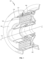
Figure 1 is a perspective view of a section through a typical brake assembly. -
Figure 2 shows a conventional clip with a rivet fastener. -
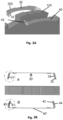
Figure 3A is a perspective side view showing a clip according to the disclosure, being assembled. -
Figure 3B shows the clip being assembled from a top view. -
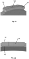
Figure 4A shows a clip such as shown inFigure 3A and 3B , when attached to a rotor lug. -
Figure 4B shows the attached clip from a top view. -
Figure 5 shows a close up view of the fastening features of the clip ofFigs 3A, 3B ,4A and 4B . - Referring first to
Fig. 1 , a wheel brake assembly is shown for purposes of explanation. Thebrake assembly 100 is mounted within awheel 102 which rotates about an axis A-A' 112. The brake assembly comprises a stack ofalternate rotor disks 122 andstator disks 126 with the rotor disks rotatable with the wheel, and relative to the stator disks, aboutaxis 112. To decelerate or brake rotation of the wheel pressure is applied by means of actuators in the axial direction A-A' to the brake stack to compress the rotor and stator disks together, causing friction between the rotor and stator disks and thus slowing the wheel. The rotor disks haverotor lugs 124 defined around their circumference and extending radially outwards with respect to the axis ofrotation 112.Torque bars 108 acts as drive lugs that engage the wheel with the rotor disks via the rotor lugs. - As mentioned above, in order to protect the rotor disk material against wear, the
rotor lugs 124 may be provided withprotective clips 123 via which the torque is transferred from thetorque bars 108 to therotor lugs 124, and hence to the rotor disk. During use, the operation of the brake assembly will cause thebrake clips 123 to wear before the rotor disk material wears, and theclips 123 can be removed and new clips fitted, without needing to replace the entire rotor disk. - Conventionally, these clips are attached to the rotor disks or rotor lugs by means of rivets. An example of such known clip designs is shown in
Fig. 2 . -
Fig. 2 shows a so-calledhalf cap clip 10 which has at least one rivet aperture 12 (in this example, there are two rivet apertures 12). Theclip 10 is shaped to fit over the end of arotor lug 124 and is secured to the lug by means ofrivets 14 secured to the side of the lug through theclip apertures 12. As mentioned above, these rivets can be expensive and difficult to manufacture and install and a hotspot of force can occur around the region of therivet head 15. - The clip according to the present disclosure, described below with reference to
Figs. 3A, 3B ,4A, 4B and5 , avoids the need for rivets for fastening the clip to the rotor disk. - The
clip 200 according to the disclosure is formed from two complementary strips offlexible sheet metal rotor lug 124 and each defining a body 30', 40' between twoends first end 31 of a first of the twostrips 30 overlaps afirst end 41 of thesecond strip 40 at an end of the rotor lug and asecond end 32 of the first strip and asecond end 42 of thesecond strip 40 overlap at the other end of the rotor lug, and wherein the overlappingfirst ends first pin 33 protruding from one of thefirst ends first aperture 43 formed in the other of thefirst ends first pin 33 locates, and the overlappingsecond ends second pin 34 protruding from one of thesecond ends second aperture 44 formed in the other of thesecond ends second pin 34 locates. - The two complementary strips of flexible sheet material are formed of a material that has some resilience and are formed by bending the
ends first strip 30 in a first direction and by bending theends second strip 42 in an opposite direction such that the strips have some degree of pre-tensioning due to the bending so that when they are fitted together the resilience of the strips biases the ends together such that the pins and the apertures engage and remain in engagement. - To assemble the
clip 200 onto therotor lug 124, thefirst strip 30 is fitted along a first side of thelug 124 and thesecond strip 40 is fitted along the opposite side of thelug 124. The first andsecond ends second strip 40 are slightly opened out away from the lug and are then fitted over the first andsecond ends pins first strip 30 at the ends of the lug are received in theapertures second strip 40 as the ends of the second strip elastically move back in towards the ends of thelug 124. Thestrips clip 200 fits snugly around therotor lug 124 and is held in a form fitting engagement to the lug. - Forming the
clip 200 of two sheet metal halves makes it simple and inexpensive to manufacture and install and to remove, as needed. - The clip is simple and lightweight and offers good thermal behaviour in that all parts are made of the same material, thus avoiding hot spots. Because the fastening pin and aperture are formed in the metal strips, no additional fasteners are required adding to the simplicity, light weight and low cost of the clip.
Claims (7)
- A clip for a rotor disk of a brake assembly, the clip comprising: a first half comprising a first sheet metal strip (30) having a body portion (30') and a first end (31) and a second end (32) bent in a first direction relative to the body portion; and a second half comprising a second sheet metal strip (40) having a body portion (40') having a length the same as the length of the body portion (30') of the first sheet metal strip (30), the second sheet metal strip having a first end (41) and a second end (42) bent in a second direction, opposite to the first direction, relative to the body portion (40') of the second sheet metal strip; and wherein one of the first end of the first sheet metal strip and the first end of the second sheet metal strip is provided with a first pin (33) protruding from the end and the other of the first end of the first sheet metal strip and the second sheet metal strip is provided with a first aperture (43) configured to receive the first pin when the first and second sheet metal strips are assembled such that their first ends overlap; and wherein one of the second end of the first sheet metal strip and the second end of the second sheet metal strip is provided with a second pin (34) protruding from the end and the other of the second end of the first sheet metal strip and the second sheet metal strip is provided with a second aperture (44) configured to receive the second pin when the first and second sheet metal strips are assembled such that their second ends overlap.
- A method of providing a clip to a rotor disk of a brake assembly, the method comprising fitting a first sheet metal strip (30) having a body portion (30') and a first end (31) and a second end (32) bent in a first direction relative to the body portion to a first side of a lug of the rotor; fitting a second sheet metal strip (40) having a body portion (40') having a length the same as the length of the body portion (30') of the first sheet metal strip (30), to a second, opposite side of the lug of the rotor, the second sheet metal strip having a first end (41) and a second end (42) bent in a second direction, opposite to the first direction, relative to the body portion (40') of the second sheet metal strip; overlapping the first ends of the first and second metal strips and overlapping the second ends of the first and second metal strips, securing the first end of the first metal strip and the first end of the second metal strip together by receiving a pin provided on one of the first ends in an aperture provided in the other of the first ends; and securing the second end of the first metal strip and the second end of the second metal strip together by receiving a pin provided on one of the second ends in an aperture provided in the other of the second ends.
- A rotor disk of a brake assembly provided with a plurality of rotor lugs around and radially extending from its circumference; and a clip as claimed in claim 1 mounted to each rotor lug.
- A brake assembly comprising a plurality of rotor disks as claimed in claim 3 and a plurality of stator disks, the stator disks and the rotor disks arranged alternately to form a brake stack.
- A wheel assembly comprising a wheel having an inner diameter within which is mounted a brake assembly as claimed in claim 4.
- A wheel assembly as claimed in claim 5, the wheel having an outer diameter onto which a tire is mounted.
- A wheel assembly as claimed in claim 5 or 6 being a wheel assembly for the landing gear of an aircraft.
Priority Applications (2)
| Application Number | Priority Date | Filing Date | Title |
|---|---|---|---|
| EP21461600.5A EP4155570B1 (en) | 2021-09-24 | 2021-09-24 | Rotor clip for brake assembly |
| US17/901,684 US11746844B2 (en) | 2021-09-24 | 2022-09-01 | Rotor clip for brake assembly |
Applications Claiming Priority (1)
| Application Number | Priority Date | Filing Date | Title |
|---|---|---|---|
| EP21461600.5A EP4155570B1 (en) | 2021-09-24 | 2021-09-24 | Rotor clip for brake assembly |
Publications (2)
| Publication Number | Publication Date |
|---|---|
| EP4155570A1 true EP4155570A1 (en) | 2023-03-29 |
| EP4155570B1 EP4155570B1 (en) | 2024-04-17 |
Family
ID=77951652
Family Applications (1)
| Application Number | Title | Priority Date | Filing Date |
|---|---|---|---|
| EP21461600.5A Active EP4155570B1 (en) | 2021-09-24 | 2021-09-24 | Rotor clip for brake assembly |
Country Status (2)
| Country | Link |
|---|---|
| US (1) | US11746844B2 (en) |
| EP (1) | EP4155570B1 (en) |
Families Citing this family (1)
| Publication number | Priority date | Publication date | Assignee | Title |
|---|---|---|---|---|
| EP4293246B1 (en) * | 2022-06-13 | 2025-02-19 | Goodrich Corporation | Rotor clip for brake assembly |
Citations (6)
| Publication number | Priority date | Publication date | Assignee | Title |
|---|---|---|---|---|
| JPS60234140A (en) * | 1984-04-30 | 1985-11-20 | グツドイアー エアロスペース コーポレーシヨン | Friction disc |
| US4863001A (en) * | 1987-02-18 | 1989-09-05 | The Bf Goodrich Company | Brake apparatus |
| US20080296109A1 (en) * | 2007-06-04 | 2008-12-04 | James Jay Cress | Insert and retainer for securing same to an aircraft brake disk |
| US20180128331A1 (en) * | 2016-11-09 | 2018-05-10 | Goodrich Corporation | Bridged clip retainer for brake system |
| US20190017562A1 (en) * | 2017-07-12 | 2019-01-17 | Goodrich Corporation | Wear liner with integrated torque button |
| US20190048949A1 (en) * | 2017-08-10 | 2019-02-14 | Goodrich Corporation | Rivet-less rotor clip design |
Family Cites Families (3)
| Publication number | Priority date | Publication date | Assignee | Title |
|---|---|---|---|---|
| US4465165A (en) | 1983-01-28 | 1984-08-14 | The B. F. Goodrich Company | Brake apparatus |
| US4511021A (en) * | 1983-04-21 | 1985-04-16 | The B. F. Goodrich Company | Brake apparatus |
| US7802758B2 (en) * | 2007-05-04 | 2010-09-28 | Honeywell International Inc. | Load-distributing rotor insert for aircraft brakes |
-
2021
- 2021-09-24 EP EP21461600.5A patent/EP4155570B1/en active Active
-
2022
- 2022-09-01 US US17/901,684 patent/US11746844B2/en active Active
Patent Citations (6)
| Publication number | Priority date | Publication date | Assignee | Title |
|---|---|---|---|---|
| JPS60234140A (en) * | 1984-04-30 | 1985-11-20 | グツドイアー エアロスペース コーポレーシヨン | Friction disc |
| US4863001A (en) * | 1987-02-18 | 1989-09-05 | The Bf Goodrich Company | Brake apparatus |
| US20080296109A1 (en) * | 2007-06-04 | 2008-12-04 | James Jay Cress | Insert and retainer for securing same to an aircraft brake disk |
| US20180128331A1 (en) * | 2016-11-09 | 2018-05-10 | Goodrich Corporation | Bridged clip retainer for brake system |
| US20190017562A1 (en) * | 2017-07-12 | 2019-01-17 | Goodrich Corporation | Wear liner with integrated torque button |
| US20190048949A1 (en) * | 2017-08-10 | 2019-02-14 | Goodrich Corporation | Rivet-less rotor clip design |
Also Published As
| Publication number | Publication date |
|---|---|
| US20230116460A1 (en) | 2023-04-13 |
| US11746844B2 (en) | 2023-09-05 |
| EP4155570B1 (en) | 2024-04-17 |
Similar Documents
| Publication | Publication Date | Title |
|---|---|---|
| US4222476A (en) | Torsion damping device for friction plate having a flexible center | |
| US4676356A (en) | Multiple rotating disk assembly with elastic separator means | |
| EP3563073B1 (en) | Floating rotor disc brake with marcel expander ring attachment | |
| EP3489538A1 (en) | Segmented wear liner | |
| US20140000991A1 (en) | Disc Brake | |
| US12486878B2 (en) | Rotor clip for brake assembly | |
| GB2167504A (en) | Friction material and carrier plate assembly | |
| US11746844B2 (en) | Rotor clip for brake assembly | |
| KR20210149692A (en) | Multi-disc clutch for hybrid drivetrain | |
| EP3418601B1 (en) | Multi-disk brake assembly with travel limit pin | |
| US12571442B2 (en) | Rotor clip for brake assembly | |
| US12498008B2 (en) | Rotor clip for brake assembly | |
| EP0096553B1 (en) | Disc assemblies for brakes | |
| EP4283154B1 (en) | Stator clip for brake assembly | |
| EP4290093B1 (en) | Rotor clip for brake assembly | |
| US4607738A (en) | Friction clutch cover assemblies | |
| EP3404283B1 (en) | Extended torque tube | |
| GB2054099A (en) | Torsion damping assembly for a friction clutch | |
| KR101524423B1 (en) | Clutch friction disk | |
| US4000791A (en) | Disk brake for reinforced drive key member | |
| US5803222A (en) | Torque transmitting friction mechanism with a plate having a reaction tab | |
| EP4403790B1 (en) | Heat shield assembly | |
| EP0252600A2 (en) | Cover assembly for a friction clutch | |
| EP4321769B1 (en) | Heat shield panel | |
| EP3798463B1 (en) | Carbon brake stack assembly for improved life |
Legal Events
| Date | Code | Title | Description |
|---|---|---|---|
| PUAI | Public reference made under article 153(3) epc to a published international application that has entered the european phase |
Free format text: ORIGINAL CODE: 0009012 |
|
| STAA | Information on the status of an ep patent application or granted ep patent |
Free format text: STATUS: THE APPLICATION HAS BEEN PUBLISHED |
|
| AK | Designated contracting states |
Kind code of ref document: A1 Designated state(s): AL AT BE BG CH CY CZ DE DK EE ES FI FR GB GR HR HU IE IS IT LI LT LU LV MC MK MT NL NO PL PT RO RS SE SI SK SM TR |
|
| STAA | Information on the status of an ep patent application or granted ep patent |
Free format text: STATUS: REQUEST FOR EXAMINATION WAS MADE |
|
| 17P | Request for examination filed |
Effective date: 20230928 |
|
| P01 | Opt-out of the competence of the unified patent court (upc) registered |
Effective date: 20230922 |
|
| RBV | Designated contracting states (corrected) |
Designated state(s): AL AT BE BG CH CY CZ DE DK EE ES FI FR GB GR HR HU IE IS IT LI LT LU LV MC MK MT NL NO PL PT RO RS SE SI SK SM TR |
|
| GRAP | Despatch of communication of intention to grant a patent |
Free format text: ORIGINAL CODE: EPIDOSNIGR1 |
|
| STAA | Information on the status of an ep patent application or granted ep patent |
Free format text: STATUS: GRANT OF PATENT IS INTENDED |
|
| RIC1 | Information provided on ipc code assigned before grant |
Ipc: F16D 65/12 20060101AFI20231102BHEP |
|
| INTG | Intention to grant announced |
Effective date: 20231123 |
|
| GRAS | Grant fee paid |
Free format text: ORIGINAL CODE: EPIDOSNIGR3 |
|
| GRAA | (expected) grant |
Free format text: ORIGINAL CODE: 0009210 |
|
| STAA | Information on the status of an ep patent application or granted ep patent |
Free format text: STATUS: THE PATENT HAS BEEN GRANTED |
|
| AK | Designated contracting states |
Kind code of ref document: B1 Designated state(s): AL AT BE BG CH CY CZ DE DK EE ES FI FR GB GR HR HU IE IS IT LI LT LU LV MC MK MT NL NO PL PT RO RS SE SI SK SM TR |
|
| REG | Reference to a national code |
Ref country code: GB Ref legal event code: FG4D |
|
| REG | Reference to a national code |
Ref country code: CH Ref legal event code: EP |
|
| REG | Reference to a national code |
Ref country code: IE Ref legal event code: FG4D Ref country code: DE Ref legal event code: R096 Ref document number: 602021011919 Country of ref document: DE |
|
| REG | Reference to a national code |
Ref country code: LT Ref legal event code: MG9D |
|
| REG | Reference to a national code |
Ref country code: NL Ref legal event code: MP Effective date: 20240417 |
|
| REG | Reference to a national code |
Ref country code: AT Ref legal event code: MK05 Ref document number: 1677521 Country of ref document: AT Kind code of ref document: T Effective date: 20240417 |
|
| PG25 | Lapsed in a contracting state [announced via postgrant information from national office to epo] |
Ref country code: NL Free format text: LAPSE BECAUSE OF FAILURE TO SUBMIT A TRANSLATION OF THE DESCRIPTION OR TO PAY THE FEE WITHIN THE PRESCRIBED TIME-LIMIT Effective date: 20240417 |
|
| PG25 | Lapsed in a contracting state [announced via postgrant information from national office to epo] |
Ref country code: NL Free format text: LAPSE BECAUSE OF FAILURE TO SUBMIT A TRANSLATION OF THE DESCRIPTION OR TO PAY THE FEE WITHIN THE PRESCRIBED TIME-LIMIT Effective date: 20240417 |
|
| PG25 | Lapsed in a contracting state [announced via postgrant information from national office to epo] |
Ref country code: IS Free format text: LAPSE BECAUSE OF FAILURE TO SUBMIT A TRANSLATION OF THE DESCRIPTION OR TO PAY THE FEE WITHIN THE PRESCRIBED TIME-LIMIT Effective date: 20240817 |
|
| PG25 | Lapsed in a contracting state [announced via postgrant information from national office to epo] |
Ref country code: BG Free format text: LAPSE BECAUSE OF FAILURE TO SUBMIT A TRANSLATION OF THE DESCRIPTION OR TO PAY THE FEE WITHIN THE PRESCRIBED TIME-LIMIT Effective date: 20240417 |
|
| PG25 | Lapsed in a contracting state [announced via postgrant information from national office to epo] |
Ref country code: FI Free format text: LAPSE BECAUSE OF FAILURE TO SUBMIT A TRANSLATION OF THE DESCRIPTION OR TO PAY THE FEE WITHIN THE PRESCRIBED TIME-LIMIT Effective date: 20240417 Ref country code: HR Free format text: LAPSE BECAUSE OF FAILURE TO SUBMIT A TRANSLATION OF THE DESCRIPTION OR TO PAY THE FEE WITHIN THE PRESCRIBED TIME-LIMIT Effective date: 20240417 |
|
| PG25 | Lapsed in a contracting state [announced via postgrant information from national office to epo] |
Ref country code: GR Free format text: LAPSE BECAUSE OF FAILURE TO SUBMIT A TRANSLATION OF THE DESCRIPTION OR TO PAY THE FEE WITHIN THE PRESCRIBED TIME-LIMIT Effective date: 20240718 |
|
| PG25 | Lapsed in a contracting state [announced via postgrant information from national office to epo] |
Ref country code: PT Free format text: LAPSE BECAUSE OF FAILURE TO SUBMIT A TRANSLATION OF THE DESCRIPTION OR TO PAY THE FEE WITHIN THE PRESCRIBED TIME-LIMIT Effective date: 20240819 |
|
| PG25 | Lapsed in a contracting state [announced via postgrant information from national office to epo] |
Ref country code: ES Free format text: LAPSE BECAUSE OF FAILURE TO SUBMIT A TRANSLATION OF THE DESCRIPTION OR TO PAY THE FEE WITHIN THE PRESCRIBED TIME-LIMIT Effective date: 20240417 |
|
| PG25 | Lapsed in a contracting state [announced via postgrant information from national office to epo] |
Ref country code: AT Free format text: LAPSE BECAUSE OF FAILURE TO SUBMIT A TRANSLATION OF THE DESCRIPTION OR TO PAY THE FEE WITHIN THE PRESCRIBED TIME-LIMIT Effective date: 20240417 |
|
| PG25 | Lapsed in a contracting state [announced via postgrant information from national office to epo] |
Ref country code: PL Free format text: LAPSE BECAUSE OF FAILURE TO SUBMIT A TRANSLATION OF THE DESCRIPTION OR TO PAY THE FEE WITHIN THE PRESCRIBED TIME-LIMIT Effective date: 20240417 |
|
| PG25 | Lapsed in a contracting state [announced via postgrant information from national office to epo] |
Ref country code: LV Free format text: LAPSE BECAUSE OF FAILURE TO SUBMIT A TRANSLATION OF THE DESCRIPTION OR TO PAY THE FEE WITHIN THE PRESCRIBED TIME-LIMIT Effective date: 20240417 |
|
| PG25 | Lapsed in a contracting state [announced via postgrant information from national office to epo] |
Ref country code: PT Free format text: LAPSE BECAUSE OF FAILURE TO SUBMIT A TRANSLATION OF THE DESCRIPTION OR TO PAY THE FEE WITHIN THE PRESCRIBED TIME-LIMIT Effective date: 20240819 Ref country code: PL Free format text: LAPSE BECAUSE OF FAILURE TO SUBMIT A TRANSLATION OF THE DESCRIPTION OR TO PAY THE FEE WITHIN THE PRESCRIBED TIME-LIMIT Effective date: 20240417 Ref country code: NO Free format text: LAPSE BECAUSE OF FAILURE TO SUBMIT A TRANSLATION OF THE DESCRIPTION OR TO PAY THE FEE WITHIN THE PRESCRIBED TIME-LIMIT Effective date: 20240717 Ref country code: LV Free format text: LAPSE BECAUSE OF FAILURE TO SUBMIT A TRANSLATION OF THE DESCRIPTION OR TO PAY THE FEE WITHIN THE PRESCRIBED TIME-LIMIT Effective date: 20240417 Ref country code: IS Free format text: LAPSE BECAUSE OF FAILURE TO SUBMIT A TRANSLATION OF THE DESCRIPTION OR TO PAY THE FEE WITHIN THE PRESCRIBED TIME-LIMIT Effective date: 20240817 Ref country code: HR Free format text: LAPSE BECAUSE OF FAILURE TO SUBMIT A TRANSLATION OF THE DESCRIPTION OR TO PAY THE FEE WITHIN THE PRESCRIBED TIME-LIMIT Effective date: 20240417 Ref country code: GR Free format text: LAPSE BECAUSE OF FAILURE TO SUBMIT A TRANSLATION OF THE DESCRIPTION OR TO PAY THE FEE WITHIN THE PRESCRIBED TIME-LIMIT Effective date: 20240718 Ref country code: FI Free format text: LAPSE BECAUSE OF FAILURE TO SUBMIT A TRANSLATION OF THE DESCRIPTION OR TO PAY THE FEE WITHIN THE PRESCRIBED TIME-LIMIT Effective date: 20240417 Ref country code: ES Free format text: LAPSE BECAUSE OF FAILURE TO SUBMIT A TRANSLATION OF THE DESCRIPTION OR TO PAY THE FEE WITHIN THE PRESCRIBED TIME-LIMIT Effective date: 20240417 Ref country code: BG Free format text: LAPSE BECAUSE OF FAILURE TO SUBMIT A TRANSLATION OF THE DESCRIPTION OR TO PAY THE FEE WITHIN THE PRESCRIBED TIME-LIMIT Effective date: 20240417 Ref country code: AT Free format text: LAPSE BECAUSE OF FAILURE TO SUBMIT A TRANSLATION OF THE DESCRIPTION OR TO PAY THE FEE WITHIN THE PRESCRIBED TIME-LIMIT Effective date: 20240417 Ref country code: RS Free format text: LAPSE BECAUSE OF FAILURE TO SUBMIT A TRANSLATION OF THE DESCRIPTION OR TO PAY THE FEE WITHIN THE PRESCRIBED TIME-LIMIT Effective date: 20240717 |
|
| PG25 | Lapsed in a contracting state [announced via postgrant information from national office to epo] |
Ref country code: DK Free format text: LAPSE BECAUSE OF FAILURE TO SUBMIT A TRANSLATION OF THE DESCRIPTION OR TO PAY THE FEE WITHIN THE PRESCRIBED TIME-LIMIT Effective date: 20240417 |
|
| REG | Reference to a national code |
Ref country code: DE Ref legal event code: R097 Ref document number: 602021011919 Country of ref document: DE |
|
| PG25 | Lapsed in a contracting state [announced via postgrant information from national office to epo] |
Ref country code: EE Free format text: LAPSE BECAUSE OF FAILURE TO SUBMIT A TRANSLATION OF THE DESCRIPTION OR TO PAY THE FEE WITHIN THE PRESCRIBED TIME-LIMIT Effective date: 20240417 |
|
| PG25 | Lapsed in a contracting state [announced via postgrant information from national office to epo] |
Ref country code: CZ Free format text: LAPSE BECAUSE OF FAILURE TO SUBMIT A TRANSLATION OF THE DESCRIPTION OR TO PAY THE FEE WITHIN THE PRESCRIBED TIME-LIMIT Effective date: 20240417 |
|
| PG25 | Lapsed in a contracting state [announced via postgrant information from national office to epo] |
Ref country code: SK Free format text: LAPSE BECAUSE OF FAILURE TO SUBMIT A TRANSLATION OF THE DESCRIPTION OR TO PAY THE FEE WITHIN THE PRESCRIBED TIME-LIMIT Effective date: 20240417 Ref country code: RO Free format text: LAPSE BECAUSE OF FAILURE TO SUBMIT A TRANSLATION OF THE DESCRIPTION OR TO PAY THE FEE WITHIN THE PRESCRIBED TIME-LIMIT Effective date: 20240417 |
|
| PG25 | Lapsed in a contracting state [announced via postgrant information from national office to epo] |
Ref country code: SM Free format text: LAPSE BECAUSE OF FAILURE TO SUBMIT A TRANSLATION OF THE DESCRIPTION OR TO PAY THE FEE WITHIN THE PRESCRIBED TIME-LIMIT Effective date: 20240417 |
|
| PG25 | Lapsed in a contracting state [announced via postgrant information from national office to epo] |
Ref country code: SM Free format text: LAPSE BECAUSE OF FAILURE TO SUBMIT A TRANSLATION OF THE DESCRIPTION OR TO PAY THE FEE WITHIN THE PRESCRIBED TIME-LIMIT Effective date: 20240417 Ref country code: SK Free format text: LAPSE BECAUSE OF FAILURE TO SUBMIT A TRANSLATION OF THE DESCRIPTION OR TO PAY THE FEE WITHIN THE PRESCRIBED TIME-LIMIT Effective date: 20240417 Ref country code: RO Free format text: LAPSE BECAUSE OF FAILURE TO SUBMIT A TRANSLATION OF THE DESCRIPTION OR TO PAY THE FEE WITHIN THE PRESCRIBED TIME-LIMIT Effective date: 20240417 Ref country code: EE Free format text: LAPSE BECAUSE OF FAILURE TO SUBMIT A TRANSLATION OF THE DESCRIPTION OR TO PAY THE FEE WITHIN THE PRESCRIBED TIME-LIMIT Effective date: 20240417 Ref country code: DK Free format text: LAPSE BECAUSE OF FAILURE TO SUBMIT A TRANSLATION OF THE DESCRIPTION OR TO PAY THE FEE WITHIN THE PRESCRIBED TIME-LIMIT Effective date: 20240417 Ref country code: CZ Free format text: LAPSE BECAUSE OF FAILURE TO SUBMIT A TRANSLATION OF THE DESCRIPTION OR TO PAY THE FEE WITHIN THE PRESCRIBED TIME-LIMIT Effective date: 20240417 |
|
| PG25 | Lapsed in a contracting state [announced via postgrant information from national office to epo] |
Ref country code: IT Free format text: LAPSE BECAUSE OF FAILURE TO SUBMIT A TRANSLATION OF THE DESCRIPTION OR TO PAY THE FEE WITHIN THE PRESCRIBED TIME-LIMIT Effective date: 20240417 |
|
| PLBE | No opposition filed within time limit |
Free format text: ORIGINAL CODE: 0009261 |
|
| STAA | Information on the status of an ep patent application or granted ep patent |
Free format text: STATUS: NO OPPOSITION FILED WITHIN TIME LIMIT |
|
| 26N | No opposition filed |
Effective date: 20250120 |
|
| REG | Reference to a national code |
Ref country code: DE Ref legal event code: R119 Ref document number: 602021011919 Country of ref document: DE |
|
| PG25 | Lapsed in a contracting state [announced via postgrant information from national office to epo] |
Ref country code: SI Free format text: LAPSE BECAUSE OF FAILURE TO SUBMIT A TRANSLATION OF THE DESCRIPTION OR TO PAY THE FEE WITHIN THE PRESCRIBED TIME-LIMIT Effective date: 20240417 Ref country code: MC Free format text: LAPSE BECAUSE OF FAILURE TO SUBMIT A TRANSLATION OF THE DESCRIPTION OR TO PAY THE FEE WITHIN THE PRESCRIBED TIME-LIMIT Effective date: 20240417 |
|
| REG | Reference to a national code |
Ref country code: CH Ref legal event code: PL |
|
| PG25 | Lapsed in a contracting state [announced via postgrant information from national office to epo] |
Ref country code: LU Free format text: LAPSE BECAUSE OF NON-PAYMENT OF DUE FEES Effective date: 20240924 |
|
| PG25 | Lapsed in a contracting state [announced via postgrant information from national office to epo] |
Ref country code: DE Free format text: LAPSE BECAUSE OF NON-PAYMENT OF DUE FEES Effective date: 20250401 |
|
| REG | Reference to a national code |
Ref country code: BE Ref legal event code: MM Effective date: 20240930 |
|
| PG25 | Lapsed in a contracting state [announced via postgrant information from national office to epo] |
Ref country code: BE Free format text: LAPSE BECAUSE OF NON-PAYMENT OF DUE FEES Effective date: 20240930 |
|
| PG25 | Lapsed in a contracting state [announced via postgrant information from national office to epo] |
Ref country code: CH Free format text: LAPSE BECAUSE OF NON-PAYMENT OF DUE FEES Effective date: 20240930 |
|
| PG25 | Lapsed in a contracting state [announced via postgrant information from national office to epo] |
Ref country code: IE Free format text: LAPSE BECAUSE OF NON-PAYMENT OF DUE FEES Effective date: 20240924 |
|
| PG25 | Lapsed in a contracting state [announced via postgrant information from national office to epo] |
Ref country code: SE Free format text: LAPSE BECAUSE OF FAILURE TO SUBMIT A TRANSLATION OF THE DESCRIPTION OR TO PAY THE FEE WITHIN THE PRESCRIBED TIME-LIMIT Effective date: 20240417 |
|
| PGFP | Annual fee paid to national office [announced via postgrant information from national office to epo] |
Ref country code: GB Payment date: 20250827 Year of fee payment: 5 |
|
| PGFP | Annual fee paid to national office [announced via postgrant information from national office to epo] |
Ref country code: FR Payment date: 20250820 Year of fee payment: 5 |
|
| PG25 | Lapsed in a contracting state [announced via postgrant information from national office to epo] |
Ref country code: CY Free format text: LAPSE BECAUSE OF FAILURE TO SUBMIT A TRANSLATION OF THE DESCRIPTION OR TO PAY THE FEE WITHIN THE PRESCRIBED TIME-LIMIT; INVALID AB INITIO Effective date: 20210924 |
|
| PG25 | Lapsed in a contracting state [announced via postgrant information from national office to epo] |
Ref country code: HU Free format text: LAPSE BECAUSE OF FAILURE TO SUBMIT A TRANSLATION OF THE DESCRIPTION OR TO PAY THE FEE WITHIN THE PRESCRIBED TIME-LIMIT; INVALID AB INITIO Effective date: 20210924 |