EP4155557A1 - Fluid pressure cylinder movement time sensor - Google Patents
Fluid pressure cylinder movement time sensor Download PDFInfo
- Publication number
- EP4155557A1 EP4155557A1 EP22191857.6A EP22191857A EP4155557A1 EP 4155557 A1 EP4155557 A1 EP 4155557A1 EP 22191857 A EP22191857 A EP 22191857A EP 4155557 A1 EP4155557 A1 EP 4155557A1
- Authority
- EP
- European Patent Office
- Prior art keywords
- piston
- flux density
- magnetic flux
- threshold value
- end point
- Prior art date
- Legal status (The legal status is an assumption and is not a legal conclusion. Google has not performed a legal analysis and makes no representation as to the accuracy of the status listed.)
- Granted
Links
Images


Classifications
-
- F—MECHANICAL ENGINEERING; LIGHTING; HEATING; WEAPONS; BLASTING
- F15—FLUID-PRESSURE ACTUATORS; HYDRAULICS OR PNEUMATICS IN GENERAL
- F15B—SYSTEMS ACTING BY MEANS OF FLUIDS IN GENERAL; FLUID-PRESSURE ACTUATORS, e.g. SERVOMOTORS; DETAILS OF FLUID-PRESSURE SYSTEMS, NOT OTHERWISE PROVIDED FOR
- F15B19/00—Testing; Calibrating; Fault detection or monitoring; Simulation or modelling of fluid-pressure systems or apparatus not otherwise provided for
- F15B19/005—Fault detection or monitoring
-
- F—MECHANICAL ENGINEERING; LIGHTING; HEATING; WEAPONS; BLASTING
- F15—FLUID-PRESSURE ACTUATORS; HYDRAULICS OR PNEUMATICS IN GENERAL
- F15B—SYSTEMS ACTING BY MEANS OF FLUIDS IN GENERAL; FLUID-PRESSURE ACTUATORS, e.g. SERVOMOTORS; DETAILS OF FLUID-PRESSURE SYSTEMS, NOT OTHERWISE PROVIDED FOR
- F15B15/00—Fluid-actuated devices for displacing a member from one position to another; Gearing associated therewith
- F15B15/20—Other details, e.g. assembly with regulating devices
- F15B15/28—Means for indicating the position, e.g. end of stroke
- F15B15/2815—Position sensing, i.e. means for continuous measurement of position, e.g. LVDT
- F15B15/2861—Position sensing, i.e. means for continuous measurement of position, e.g. LVDT using magnetic means
-
- G—PHYSICS
- G01—MEASURING; TESTING
- G01P—MEASURING LINEAR OR ANGULAR SPEED, ACCELERATION, DECELERATION, OR SHOCK; INDICATING PRESENCE, ABSENCE, OR DIRECTION, OF MOVEMENT
- G01P3/00—Measuring linear or angular speed; Measuring differences of linear or angular speeds
- G01P3/42—Devices characterised by the use of electric or magnetic means
- G01P3/50—Devices characterised by the use of electric or magnetic means for measuring linear speed
-
- F—MECHANICAL ENGINEERING; LIGHTING; HEATING; WEAPONS; BLASTING
- F15—FLUID-PRESSURE ACTUATORS; HYDRAULICS OR PNEUMATICS IN GENERAL
- F15B—SYSTEMS ACTING BY MEANS OF FLUIDS IN GENERAL; FLUID-PRESSURE ACTUATORS, e.g. SERVOMOTORS; DETAILS OF FLUID-PRESSURE SYSTEMS, NOT OTHERWISE PROVIDED FOR
- F15B15/00—Fluid-actuated devices for displacing a member from one position to another; Gearing associated therewith
- F15B15/20—Other details, e.g. assembly with regulating devices
- F15B15/202—Externally-operated valves mounted in or on the actuator
-
- F—MECHANICAL ENGINEERING; LIGHTING; HEATING; WEAPONS; BLASTING
- F15—FLUID-PRESSURE ACTUATORS; HYDRAULICS OR PNEUMATICS IN GENERAL
- F15B—SYSTEMS ACTING BY MEANS OF FLUIDS IN GENERAL; FLUID-PRESSURE ACTUATORS, e.g. SERVOMOTORS; DETAILS OF FLUID-PRESSURE SYSTEMS, NOT OTHERWISE PROVIDED FOR
- F15B15/00—Fluid-actuated devices for displacing a member from one position to another; Gearing associated therewith
- F15B15/20—Other details, e.g. assembly with regulating devices
- F15B15/22—Other details, e.g. assembly with regulating devices for accelerating or decelerating the stroke
- F15B15/228—Other details, e.g. assembly with regulating devices for accelerating or decelerating the stroke having shock absorbers mounted outside the actuator housing
-
- F—MECHANICAL ENGINEERING; LIGHTING; HEATING; WEAPONS; BLASTING
- F15—FLUID-PRESSURE ACTUATORS; HYDRAULICS OR PNEUMATICS IN GENERAL
- F15B—SYSTEMS ACTING BY MEANS OF FLUIDS IN GENERAL; FLUID-PRESSURE ACTUATORS, e.g. SERVOMOTORS; DETAILS OF FLUID-PRESSURE SYSTEMS, NOT OTHERWISE PROVIDED FOR
- F15B2211/00—Circuits for servomotor systems
- F15B2211/40—Flow control
- F15B2211/405—Flow control characterised by the type of flow control means or valve
- F15B2211/40515—Flow control characterised by the type of flow control means or valve with variable throttles or orifices
-
- F—MECHANICAL ENGINEERING; LIGHTING; HEATING; WEAPONS; BLASTING
- F15—FLUID-PRESSURE ACTUATORS; HYDRAULICS OR PNEUMATICS IN GENERAL
- F15B—SYSTEMS ACTING BY MEANS OF FLUIDS IN GENERAL; FLUID-PRESSURE ACTUATORS, e.g. SERVOMOTORS; DETAILS OF FLUID-PRESSURE SYSTEMS, NOT OTHERWISE PROVIDED FOR
- F15B2211/00—Circuits for servomotor systems
- F15B2211/40—Flow control
- F15B2211/405—Flow control characterised by the type of flow control means or valve
- F15B2211/40576—Assemblies of multiple valves
- F15B2211/40584—Assemblies of multiple valves the flow control means arranged in parallel with a check valve
-
- F—MECHANICAL ENGINEERING; LIGHTING; HEATING; WEAPONS; BLASTING
- F15—FLUID-PRESSURE ACTUATORS; HYDRAULICS OR PNEUMATICS IN GENERAL
- F15B—SYSTEMS ACTING BY MEANS OF FLUIDS IN GENERAL; FLUID-PRESSURE ACTUATORS, e.g. SERVOMOTORS; DETAILS OF FLUID-PRESSURE SYSTEMS, NOT OTHERWISE PROVIDED FOR
- F15B2211/00—Circuits for servomotor systems
- F15B2211/60—Circuit components or control therefor
- F15B2211/63—Electronic controllers
- F15B2211/6303—Electronic controllers using input signals
- F15B2211/6336—Electronic controllers using input signals representing a state of the output member, e.g. position, speed or acceleration
-
- F—MECHANICAL ENGINEERING; LIGHTING; HEATING; WEAPONS; BLASTING
- F15—FLUID-PRESSURE ACTUATORS; HYDRAULICS OR PNEUMATICS IN GENERAL
- F15B—SYSTEMS ACTING BY MEANS OF FLUIDS IN GENERAL; FLUID-PRESSURE ACTUATORS, e.g. SERVOMOTORS; DETAILS OF FLUID-PRESSURE SYSTEMS, NOT OTHERWISE PROVIDED FOR
- F15B2211/00—Circuits for servomotor systems
- F15B2211/80—Other types of control related to particular problems or conditions
- F15B2211/85—Control during special operating conditions
- F15B2211/853—Control during special operating conditions during stopping
-
- F—MECHANICAL ENGINEERING; LIGHTING; HEATING; WEAPONS; BLASTING
- F15—FLUID-PRESSURE ACTUATORS; HYDRAULICS OR PNEUMATICS IN GENERAL
- F15B—SYSTEMS ACTING BY MEANS OF FLUIDS IN GENERAL; FLUID-PRESSURE ACTUATORS, e.g. SERVOMOTORS; DETAILS OF FLUID-PRESSURE SYSTEMS, NOT OTHERWISE PROVIDED FOR
- F15B2211/00—Circuits for servomotor systems
- F15B2211/80—Other types of control related to particular problems or conditions
- F15B2211/86—Control during or prevention of abnormal conditions
- F15B2211/863—Control during or prevention of abnormal conditions the abnormal condition being a hydraulic or pneumatic failure
- F15B2211/864—Failure of an output member, e.g. actuator or motor failure
-
- F—MECHANICAL ENGINEERING; LIGHTING; HEATING; WEAPONS; BLASTING
- F15—FLUID-PRESSURE ACTUATORS; HYDRAULICS OR PNEUMATICS IN GENERAL
- F15B—SYSTEMS ACTING BY MEANS OF FLUIDS IN GENERAL; FLUID-PRESSURE ACTUATORS, e.g. SERVOMOTORS; DETAILS OF FLUID-PRESSURE SYSTEMS, NOT OTHERWISE PROVIDED FOR
- F15B2211/00—Circuits for servomotor systems
- F15B2211/80—Other types of control related to particular problems or conditions
- F15B2211/87—Detection of failures
-
- G—PHYSICS
- G01—MEASURING; TESTING
- G01D—MEASURING NOT SPECIALLY ADAPTED FOR A SPECIFIC VARIABLE; ARRANGEMENTS FOR MEASURING TWO OR MORE VARIABLES NOT COVERED IN A SINGLE OTHER SUBCLASS; TARIFF METERING APPARATUS; MEASURING OR TESTING NOT OTHERWISE PROVIDED FOR
- G01D5/00—Mechanical means for transferring the output of a sensing member; Means for converting the output of a sensing member to another variable where the form or nature of the sensing member does not constrain the means for converting; Transducers not specially adapted for a specific variable
- G01D5/12—Mechanical means for transferring the output of a sensing member; Means for converting the output of a sensing member to another variable where the form or nature of the sensing member does not constrain the means for converting; Transducers not specially adapted for a specific variable using electric or magnetic means
- G01D5/14—Mechanical means for transferring the output of a sensing member; Means for converting the output of a sensing member to another variable where the form or nature of the sensing member does not constrain the means for converting; Transducers not specially adapted for a specific variable using electric or magnetic means influencing the magnitude of a current or voltage
- G01D5/142—Mechanical means for transferring the output of a sensing member; Means for converting the output of a sensing member to another variable where the form or nature of the sensing member does not constrain the means for converting; Transducers not specially adapted for a specific variable using electric or magnetic means influencing the magnitude of a current or voltage using Hall-effect devices
- G01D5/145—Mechanical means for transferring the output of a sensing member; Means for converting the output of a sensing member to another variable where the form or nature of the sensing member does not constrain the means for converting; Transducers not specially adapted for a specific variable using electric or magnetic means influencing the magnitude of a current or voltage using Hall-effect devices influenced by the relative movement between the Hall device and magnetic fields
Definitions
- the present invention relates to a sensor that measures a time required for a piston of a fluid pressure cylinder such as an air cylinder to move by a predetermined stroke.
- the above-described fluid pressure cylinder position detecting device requires two proximity sensors (magnetic sensors). In general, if there are a plurality of positions of the sensor to be detected, it becomes necessary for a number of magnetic sensors corresponding thereto to be provided. Accordingly, in the case of measuring the time required for the piston to move from a predetermined first position to a predetermined second position, two magnetic sensors are required.
- the present invention has the object of solving the aforementioned problem.
- a fluid pressure cylinder movement time sensor is equipped with a single magnetic sensor configured to detect a magnetic flux density of a magnet mounted on a piston of a fluid pressure cylinder, and measures a time required for the piston to move by a predetermined stroke.
- the magnet is arranged so that a direction of magnetization thereof coincides with a direction of movement of the piston, and the magnetic sensor is configured to detect the magnetic flux density in a direction perpendicular to the direction of movement of the piston.
- a relationship between a position of the magnet along the direction of movement of the piston and the magnetic flux density detected by the magnetic sensor is represented by a curve including a positive local maximum value and a negative local minimum value.
- a positive value smaller than the positive local maximum value is defined as a first threshold value
- a negative value larger than the negative local minimum value is defined as a second threshold value
- a point in time at which the magnetic flux density detected by the magnetic sensor exceeds or falls below the first threshold value is defined as one of a starting point or an end point
- a point in time at which the magnetic flux density detected by the magnetic sensor exceeds or falls below the second threshold value is defined as another one of the starting point or the end point.
- the fluid pressure cylinder movement time sensor measures a time from the starting point to the end point.
- the fluid pressure cylinder movement time sensor according to the present invention is capable of determining the starting point and the end point based on the magnetic flux density detected by such a single uniaxial magnetic sensor. Accordingly, using a magnetic sensor having a simple configuration, it is possible to measure the time required for the piston to move by the predetermined stroke.
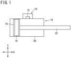
- FIG. 1 A basic configuration of a fluid pressure cylinder 14 equipped with a fluid pressure cylinder movement time sensor 10 according to an embodiment of the present invention is shown in FIG. 1 .
- a permanent magnet (magnet) 18 is mounted on a piston 16 of the fluid pressure cylinder 14.
- a direction of magnetization of the permanent magnet 18 coincides with a direction of movement (X direction) of the piston 16.
- the fluid pressure cylinder movement time sensor 10 is equipped with a magnetic sensor 12 capable of detecting a magnetic flux density of the permanent magnet 18, and is arranged on an outer side of a cylinder tube 20 of the fluid pressure cylinder 14.
- the magnetic sensor 12 is a uniaxial magnetic sensor constituted from a Hall IC or the like.
- the magnetic sensor 12 detects a magnetic flux density in a direction (Y direction) perpendicular to the direction of movement of the piston 16, and does not detect a magnetic flux density in the direction of movement of the piston 16.
- the fluid pressure cylinder movement time sensor 10 including the magnetic sensor 12 is attached to the cylinder tube 20 in a state in which the position thereof along the longitudinal direction (X direction) of the cylinder tube 20 can be adjusted.
- the fluid pressure cylinder movement time sensor 10 includes a control unit, a computation unit, a storage unit, and the like, which are constituted from a non-illustrated circuit board.
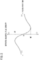
- FIG. 2 A relationship between the position of the permanent magnet 18 along the direction of movement of the piston 16 and the magnetic flux density detected by the magnetic sensor 12 is shown in FIG. 2 .
- the position of the permanent magnet 18 along the direction of movement of the piston 16 is referred to as a "piston position”.
- the magnetic flux density detected by the magnetic sensor 12 is referred to as a "detected magnetic flux density”.
- the piston position when the detected magnetic flux density is zero is set to zero.
- the detected magnetic flux density changes in a substantially linear manner between a vicinity of the local maximum value and a vicinity of the local minimum value.
- the relationship between the piston position and the detected magnetic flux density is represented by a curve in which the linearly changing portion is included.
- the curve representing the relationship between the piston position and the detected magnetic flux density is symmetrical with respect to the origin.
- the detected magnetic flux density assumes positive values in the negative region of the piston position, and the detected magnetic flux density assumes negative values in the positive region of the piston position.
- the detected magnetic flux density is equivalent to the second threshold value T2 at the two piston positions of the third position P3 and the fourth position P4, at which one of these two piston positions, the detected magnetic flux density has become equivalent to the second threshold value T2, can be determined by monitoring a change in the detected magnetic flux density. More specifically, when the detected magnetic flux density has changed from a state of being larger than the second threshold value T2 to a state of being smaller than the second threshold value T2, it can be determined that the piston 16 has passed through the third position P3. When the detected magnetic flux density has changed from a state of being smaller than the second threshold value T2 to a state of being larger than the second threshold value T2, it can be determined that the piston 16 has passed through the fourth position P4.
- a combination of the aforementioned two starting points and the aforementioned two end points is arbitrary, and there are a total of four of such combinations. From among the four combinations, in the case that the first position P1 is the starting point and the fourth position P4 is the end point, the distance between the piston position at the starting point and the piston position at the end point becomes maximum. Further, from among the four combinations, in the case that the second position P2 is the starting point and the third position P3 is the end point, the distance between the piston position at the starting point and the piston position at the end point becomes minimum.
- the piston position at the starting point is referred to as a "starting point position”
- the piston position at the end point is referred to as an "end point position”.
- the detected magnetic flux density is equivalent to the second threshold value T2 at the two piston positions of the fourth position P4 and the third position P3, at which one of these two piston positions, the detected magnetic flux density has become equivalent to the second threshold value T2, can be determined by monitoring a change in the detected magnetic flux density. More specifically, when the detected magnetic flux density has changed from a state of being larger than the second threshold value T2 to a state of being smaller than the second threshold value T2, it can be determined that the piston 16 has passed through the fourth position P4. When the detected magnetic flux density has changed from a state of being smaller than the second threshold value T2 to a state of being larger than the second threshold value T2, it can be determined that the piston 16 has passed through the third position P3.
- the detected magnetic flux density is equivalent to the first threshold value T1 at the two piston positions of the second position P2 and the first position P1, at which one of these two piston positions, the detected magnetic flux density has become equivalent to the first threshold value T1 can be determined by monitoring a change in the detected magnetic flux density. More specifically, when the detected magnetic flux density has changed from a state of being smaller than the first threshold value T1 to a state of being larger than the first threshold value T1, it can be determined that the piston 16 has passed through the second position P2. When the detected magnetic flux density has changed from a state of being larger than the first threshold value T1 to a state of being smaller than the first threshold value T1, it can be determined that the piston 16 has passed through the first position P1.
- a point in time at which the piston 16 has passed through the fourth position P4 is determined to be the starting point.
- a point in time at which the piston 16 has passed through the second position P2, or alternatively, a point in time at which the piston 16 has passed through the first position P1 is determined to be the end point. Then, by measuring the time from the starting point to the end point, the movement time of the piston 16 can be measured.
- the fluid pressure cylinder 14 is driven, whereby the piston 16 is actually moved from the specified starting point position to the specified end point position, and the detected magnetic flux density is monitored.
- the starting point position and the end point position are piston positions, such positions can be easily understood, for example, when the position of an end portion of a piston rod 22 that extends to the exterior from the cylinder tube 20 is considered, instead of the piston position.
- a condition that "the detected magnetic flux density falls below the second threshold value T2" is set as the determination condition for the end point. If the piston 16 has reached the specified end point position while the detected magnetic flux density is increasing, a condition that "the detected magnetic flux density exceeds the second threshold value T2" is set as the determination condition for the end point.
- the former is set as the second threshold value T2, and the latter is set as the first threshold value T1. If the detected magnetic flux density has decreased immediately after the piston 16 has separated away from the specified starting point position, a condition that "the detected magnetic flux density falls below the second threshold value T2" is set as the determination condition for the starting point. If the detected magnetic flux density has increased immediately after the piston 16 has separated away from the specified starting point position, a condition that "the detected magnetic flux density exceeds the second threshold value T2" is set as the determination condition for the starting point.
- a condition that "the detected magnetic flux density exceeds the first threshold value T1" is set as the determination condition for the end point. If the piston 16 has reached the specified end point position while the detected magnetic flux density is decreasing, a condition that "the detected magnetic flux density falls below the first threshold value T1" is set as the determination condition for the end point.
- the determination conditions for the starting point and the end point can be obtained by actually moving the piston 16 from the specified starting point position to the specified end point position, and monitoring the detected magnetic flux density. Including the first threshold value T1 and the second threshold value T2, these determination conditions for the starting point and the end point are stored in the storage unit or the control unit of the fluid pressure cylinder movement time sensor 10. Consequently, thereafter, the movement time of the piston 16 can be easily calculated in the computation unit of the fluid pressure cylinder movement time sensor 10.
- the piston 16 was actually moved from the position P1' to the position P3', and the detected magnetic flux density was monitored. It was monitored that the detected magnetic flux density was 3 mT when the piston position was the position P1', and the detected magnetic flux density exceeded 3 mT immediately after the piston 16 separated away from the position P1'.
- the first threshold value T1 is set to 3 mT, and a condition that "the detected magnetic flux density exceeds the first threshold value T1" is set as the determination condition for the starting point.
- the second threshold value T2 is set to -4 mT, and a condition that "the detected magnetic flux density falls below the second threshold value T2" is set as the determination condition for the end point.
- the determination conditions for the starting points and the end points are set for each of such sets. For example, a case may be presented in which it is desired to measure not only the time required for the piston 16 to move by the predetermined stroke in one direction, but also to measure the time required for the piston 16 to move by the same stroke in the opposite direction.
- the piston speed (an average value of the piston speed) on the basis of the movement time of the piston 16. More specifically, the reciprocal of the movement time of the piston 16 is multiplied by a constant corresponding to the distance from the starting point position to the end point position. According to this method, the piston speed can be calculated by the computation unit of the fluid pressure cylinder movement time sensor 10. Further, if the piston speed is obtained for a plurality of continuous segments, then a change in the piston speed can be detected.
- the first mode of use is a mode that is used to determine whether or not a buffering action of a shock absorber 24 that serves to decelerate the piston 16 is appropriate.
- the same or equivalent members as those in the basic configuration shown in FIG. 1 are designated by the same reference numerals.
- the shock absorber 24 is a fluid type shock absorber, which exerts a buffering action in the vicinity of a stroke end of the piston 16 when the piston rod 22 is pulled in.
- the magnetic sensor 12 is arranged at a position where it is capable of effectively detecting a change in the magnetic flux density of the permanent magnet 18 that is mounted on the piston 16 in the vicinity of the stroke end. Determination conditions for the starting point and the end point are appropriately set, and the movement time of the piston 16 is measured.
- reference numeral 26 indicates an end plate that is fixed to the end portion of the piston rod 22.
- the movement time of the piston 16 lies within a range of a reference time period defined by a predetermined upper limit value and a predetermined lower limit value.
- the buffering action of the shock absorber 24 is too strong, the movement time of the piston 16 becomes longer than the upper limit value.
- the buffering action of the shock absorber 24 is too weak, the movement time of the piston 16 becomes shorter than the lower limit value.
- the second mode of use is a mode that is used to obtain the piston speed on the basis of the movement time of the piston 16 in order for the user to adjust a speed controller 28 provided in the fluid pressure cylinder 14.
- the same or equivalent members as those in the basic configuration shown in FIG. 1 are designated by the same reference numerals.
- the speed controller 28 is a meter-out variable throttle valve, which throttles the flow rate of the air discharged at a time when the piston rod 22 of the fluid pressure cylinder 14 is pushed out.
- the speed controller 28 is arranged in a discharge port (not shown) of the fluid pressure cylinder 14.
- the magnetic sensor 12 is arranged at a position where it is capable of detecting a change in the magnetic flux density of the permanent magnet 18 that is mounted on the piston 16 when the piston rod 22 is pushed out. Determination conditions for the starting point and the end point are appropriately set, and the movement time of the piston 16 is measured.
- the movement time of the piston 16 is converted into a piston speed, and the piston speed is displayed on a display (not shown).
- the user observes the displayed piston speed, and in the case that the piston speed deviates from a desired value, the user manually operates the speed controller 28, and adjusts a flow path area for the air.
- the third mode of use is a mode that is used to detect that an elastic body 30 has been clamped in the fluid pressure cylinder 14, which clamps the elastic body 30 while compressing the elastic body 30.
- the same or equivalent members as those in the basic configuration shown in FIG. 1 are designated by the same reference numerals.
- the magnetic sensor 12 is arranged at a position where it is capable of detecting a change in the magnetic flux density of the permanent magnet 18 that is mounted on the piston 16, within a range in which at least a position where the piston rod 22 comes into contact with the elastic body 30 is included.
- Determination conditions are set for a plurality of sets of the starting point and the end point so that the piston speed can be obtained for a plurality of continuous segments, and the time required for the piston 16 to move in each of such segments is measured. Then, using a constant corresponding to the distance of each of such segments, the time required for the piston 16 to move in each of the segments is converted into the piston speed. When the piston speed is significantly reduced in adjacent segments, it can be determined that the elastic body 30 has been clamped by the fluid pressure cylinder 14.
- various other modes of use of the fluid pressure cylinder movement time sensor 10 may be considered.
- a mode may be considered that is used in the case that the movement time of the piston 16 is compared with the reference time period, and when the movement time of the piston 16 deviates from the reference time period, a notification is issued to the user that some type of abnormality has occurred.
- the cause of the abnormality can be assumed in accordance with the mode of use of the fluid pressure cylinder 14. For example, in the case that transportation is carried out by the fluid pressure cylinder 14, since there is a high likelihood that foreign matter being caught therein or dropping of the transported object will become a cause of the abnormality, a notification to that effect may be issued to the user.
- a mode may also be considered that is used in the case that the number of times that the movement time of the piston 16 is measured is counted, and when the cumulative number of times exceeds a predetermined value, the user is prompted to carry out necessary maintenance.
- the user since the useful lifetime of the fluid pressure cylinder 14 frequently depends on sliding portions, which are constituted from a sealing material or the like, the user may be prompted to carry out maintenance of the sliding portions.
Landscapes
- Engineering & Computer Science (AREA)
- Physics & Mathematics (AREA)
- Fluid Mechanics (AREA)
- Mechanical Engineering (AREA)
- General Engineering & Computer Science (AREA)
- General Physics & Mathematics (AREA)
- Actuator (AREA)
- Measurement Of Length, Angles, Or The Like Using Electric Or Magnetic Means (AREA)
- Measuring Fluid Pressure (AREA)
Abstract
Description
- The present invention relates to a sensor that measures a time required for a piston of a fluid pressure cylinder such as an air cylinder to move by a predetermined stroke.
- Conventionally, a fluid pressure cylinder equipped with a sensor for detecting a magnetic force of a magnet mounted on a piston, and detecting a position of the piston has been known.
- For example, in
JP 5889808 B2 - However, the above-described fluid pressure cylinder position detecting device requires two proximity sensors (magnetic sensors). In general, if there are a plurality of positions of the sensor to be detected, it becomes necessary for a number of magnetic sensors corresponding thereto to be provided. Accordingly, in the case of measuring the time required for the piston to move from a predetermined first position to a predetermined second position, two magnetic sensors are required.
- The present invention has the object of solving the aforementioned problem.
- A fluid pressure cylinder movement time sensor according to the present invention is equipped with a single magnetic sensor configured to detect a magnetic flux density of a magnet mounted on a piston of a fluid pressure cylinder, and measures a time required for the piston to move by a predetermined stroke. The magnet is arranged so that a direction of magnetization thereof coincides with a direction of movement of the piston, and the magnetic sensor is configured to detect the magnetic flux density in a direction perpendicular to the direction of movement of the piston. A relationship between a position of the magnet along the direction of movement of the piston and the magnetic flux density detected by the magnetic sensor is represented by a curve including a positive local maximum value and a negative local minimum value. A positive value smaller than the positive local maximum value is defined as a first threshold value, and a negative value larger than the negative local minimum value is defined as a second threshold value. A point in time at which the magnetic flux density detected by the magnetic sensor exceeds or falls below the first threshold value is defined as one of a starting point or an end point, and a point in time at which the magnetic flux density detected by the magnetic sensor exceeds or falls below the second threshold value is defined as another one of the starting point or the end point. In addition, the fluid pressure cylinder movement time sensor measures a time from the starting point to the end point.
- According to the above-described fluid pressure cylinder movement time sensor, the magnetic flux density detected by a single uniaxial magnetic sensor is compared with the first threshold value and the second threshold value, whereby the starting point and the end point when the piston moves by the predetermined stroke can be determined.
- The fluid pressure cylinder movement time sensor according to the present invention is capable of determining the starting point and the end point based on the magnetic flux density detected by such a single uniaxial magnetic sensor. Accordingly, using a magnetic sensor having a simple configuration, it is possible to measure the time required for the piston to move by the predetermined stroke.
- The above and other objects, features, and advantages of the present invention will become more apparent from the following description when taken in conjunction with the accompanying drawings, in which a preferred embodiment of the present invention is shown by way of illustrative example.
-
-
FIG. 1 is a diagram showing a basic configuration of a fluid pressure cylinder equipped with a fluid pressure cylinder movement time sensor according to the present invention; -
FIG. 2 is a diagram showing a relationship between a piston position in the fluid pressure cylinder ofFIG. 1 and a detected magnetic flux density; -
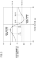
FIG. 3 is a diagram in order to describe a method for determining a starting point and an end point using threshold values of a magnetic flux density; -
FIG. 4 is a diagram in order to describe a method for setting determination conditions for the starting point and the end point; -
FIG. 5 is a diagram in order to describe a first mode of use of the fluid pressure cylinder movement time sensor according to the present invention; -
FIG. 6 is a diagram in order to describe a second mode of use of the fluid pressure cylinder movement time sensor according to the present invention; and -
FIG. 7 is a diagram in order to describe a third mode of use of the fluid pressure cylinder movement time sensor according to the present invention. - A basic configuration of a
fluid pressure cylinder 14 equipped with a fluid pressure cylindermovement time sensor 10 according to an embodiment of the present invention is shown inFIG. 1 . A permanent magnet (magnet) 18 is mounted on apiston 16 of thefluid pressure cylinder 14. A direction of magnetization of thepermanent magnet 18 coincides with a direction of movement (X direction) of thepiston 16. The fluid pressure cylindermovement time sensor 10 is equipped with amagnetic sensor 12 capable of detecting a magnetic flux density of thepermanent magnet 18, and is arranged on an outer side of acylinder tube 20 of thefluid pressure cylinder 14. - The
magnetic sensor 12 is a uniaxial magnetic sensor constituted from a Hall IC or the like. Themagnetic sensor 12 detects a magnetic flux density in a direction (Y direction) perpendicular to the direction of movement of thepiston 16, and does not detect a magnetic flux density in the direction of movement of thepiston 16. The fluid pressure cylindermovement time sensor 10 including themagnetic sensor 12 is attached to thecylinder tube 20 in a state in which the position thereof along the longitudinal direction (X direction) of thecylinder tube 20 can be adjusted. The fluid pressure cylindermovement time sensor 10 includes a control unit, a computation unit, a storage unit, and the like, which are constituted from a non-illustrated circuit board. - A relationship between the position of the
permanent magnet 18 along the direction of movement of thepiston 16 and the magnetic flux density detected by themagnetic sensor 12 is shown inFIG. 2 . Hereinafter, the position of thepermanent magnet 18 along the direction of movement of thepiston 16 is referred to as a "piston position". Further, the magnetic flux density detected by themagnetic sensor 12 is referred to as a "detected magnetic flux density". The piston position when the detected magnetic flux density is zero is set to zero. - In a negative region of the piston position, when the
piston 16 departs from a position located far away from the origin and moves until reaching the origin, the detected magnetic flux density becomes gradually larger within a range of positive values, and after having assumed a local maximum value M1, decreases in a substantially linear manner to zero. In a positive region of the piston position, when thepiston 16 departs from a position located far away from the origin and moves until reaching the origin, the detected magnetic flux density becomes gradually smaller within a range of negative values, and after having assumed a local minimum value M2, increases in a substantially linear manner to zero. - The detected magnetic flux density changes in a substantially linear manner between a vicinity of the local maximum value and a vicinity of the local minimum value. According to the present invention, for the sake of convenience, the relationship between the piston position and the detected magnetic flux density is represented by a curve in which the linearly changing portion is included. The curve representing the relationship between the piston position and the detected magnetic flux density is symmetrical with respect to the origin. Moreover, in
FIG. 2 , the detected magnetic flux density assumes positive values in the negative region of the piston position, and the detected magnetic flux density assumes negative values in the positive region of the piston position. In the case that the directions of the magnetic poles of thepermanent magnet 18 are reversed, the detected magnetic flux density assumes negative values in the negative region of the piston position, and the detected magnetic flux density assumes positive values in the positive region of the piston position. Hereinafter, although a description is given on the basis of the curve shown inFIG. 2 , the same situation also applies in a case in which the directions of the magnetic poles of thepermanent magnet 18 are reversed. - The present invention is a sensor that measures the time required for the
piston 16 to move by a predetermined stroke (hereinafter, referred to as a "movement time (or stroke time) of thepiston 16"). It is important how to determine the starting point and the end point on a time axis when thepiston 16 moves by the predetermined stroke. Hereinafter, with reference toFIG. 3 , a description will be given of a method for determining the starting point and the end point using two threshold values of the magnetic flux density. - In
FIG. 3 , a relationship between the piston position and the detected magnetic flux density is shown with specific numerical values, and two threshold values concerning the magnetic flux density are also shown. In the example shown inFIG. 3 , when the piston position is -7 mm (millimeters), the detected magnetic flux density becomes a local maximum, and a local maximum value M1 is 5 mT (millitesla). Further, when the piston position is 7 mm, the detected magnetic flux density becomes a local minimum, and a local minimum value M2 is -5 mT. The absolute value of the local minimum value M2 is equivalent to the absolute value of the local maximum value M1. - A positive value that is smaller than the local maximum value M1 is set as a first threshold value T1, and a negative value that is larger than the local maximum value M2 is set as a second threshold value T2. The absolute value of the second threshold value T2 may be the same value as the absolute value of the first threshold value T1, or may be a value that differs from the absolute value of the first threshold value T1. In the example shown in
FIG. 3 , the first threshold value T1 is 3.5 mT, the second threshold value T2 is -3.5 mT, and the absolute value of the second threshold value T2 is equivalent to the absolute value of the first threshold value T1. - Before and after the piston position at which the detected magnetic flux density becomes the local maximum, the detected magnetic flux density becomes equivalent to the first threshold value T1. More specifically, when the piston position is a first position P1 and a second position P2, the detected magnetic flux density becomes equivalent to the first threshold value T1. Further, before and after the piston position at which the detected magnetic flux density becomes the local minimum, the detected magnetic flux density becomes equivalent to the second threshold value T2. More specifically, when the piston position is a third position P3 and a fourth position P4, the detected magnetic flux density becomes equivalent to the second threshold value T2. In the example shown in
FIG. 3 , the first position P1 is -11 mm, the second position P2 is -3 mm, the third position P3 is 3 mm, and the fourth position P4 is 11 mm. - First, a case will be considered in which the
piston 16 moves from the negative region toward the positive region of the piston position. As noted previously, although the detected magnetic flux density is equivalent to the first threshold value T1 at the two piston positions of the first position P1 and the second position P2, at which one of these two piston positions, the detected magnetic flux density has become equivalent to the first threshold value T1, can be determined by monitoring a change in the detected magnetic flux density. More specifically, when the detected magnetic flux density has changed from a state of being smaller than the first threshold value T1 to a state of being larger than the first threshold value T1, it can be determined that thepiston 16 has passed through the first position P1. When the detected magnetic flux density has changed from a state of being larger than the first threshold value T1 to a state of being smaller than the first threshold value T1, it can be determined that thepiston 16 has passed through the second position P2. - Further, although the detected magnetic flux density is equivalent to the second threshold value T2 at the two piston positions of the third position P3 and the fourth position P4, at which one of these two piston positions, the detected magnetic flux density has become equivalent to the second threshold value T2, can be determined by monitoring a change in the detected magnetic flux density. More specifically, when the detected magnetic flux density has changed from a state of being larger than the second threshold value T2 to a state of being smaller than the second threshold value T2, it can be determined that the
piston 16 has passed through the third position P3. When the detected magnetic flux density has changed from a state of being smaller than the second threshold value T2 to a state of being larger than the second threshold value T2, it can be determined that thepiston 16 has passed through the fourth position P4. - Since the
piston 16 moves from the negative region toward the positive region, a point in time at which thepiston 16 has passed through the first position P1, or alternatively, a point in time at which thepiston 16 has passed through the second position P2 is determined to be the starting point. A point in time at which thepiston 16 has passed through the third position P3, or alternatively, a point in time at which thepiston 16 has passed through the fourth position P4 is determined to be the end point. Then, by measuring the time from the starting point to the end point, the movement time of thepiston 16 can be measured. - A combination of the aforementioned two starting points and the aforementioned two end points is arbitrary, and there are a total of four of such combinations. From among the four combinations, in the case that the first position P1 is the starting point and the fourth position P4 is the end point, the distance between the piston position at the starting point and the piston position at the end point becomes maximum. Further, from among the four combinations, in the case that the second position P2 is the starting point and the third position P3 is the end point, the distance between the piston position at the starting point and the piston position at the end point becomes minimum. Hereinafter, the piston position at the starting point is referred to as a "starting point position", and the piston position at the end point is referred to as an "end point position".
- Next, a case will be considered in which the
piston 16 moves from the positive region toward the negative region of the piston position. Although the detected magnetic flux density is equivalent to the second threshold value T2 at the two piston positions of the fourth position P4 and the third position P3, at which one of these two piston positions, the detected magnetic flux density has become equivalent to the second threshold value T2, can be determined by monitoring a change in the detected magnetic flux density. More specifically, when the detected magnetic flux density has changed from a state of being larger than the second threshold value T2 to a state of being smaller than the second threshold value T2, it can be determined that thepiston 16 has passed through the fourth position P4. When the detected magnetic flux density has changed from a state of being smaller than the second threshold value T2 to a state of being larger than the second threshold value T2, it can be determined that thepiston 16 has passed through the third position P3. - Further, although the detected magnetic flux density is equivalent to the first threshold value T1 at the two piston positions of the second position P2 and the first position P1, at which one of these two piston positions, the detected magnetic flux density has become equivalent to the first threshold value T1, can be determined by monitoring a change in the detected magnetic flux density. More specifically, when the detected magnetic flux density has changed from a state of being smaller than the first threshold value T1 to a state of being larger than the first threshold value T1, it can be determined that the
piston 16 has passed through the second position P2. When the detected magnetic flux density has changed from a state of being larger than the first threshold value T1 to a state of being smaller than the first threshold value T1, it can be determined that thepiston 16 has passed through the first position P1. - Since the
piston 16 moves from the positive region toward the negative region, a point in time at which thepiston 16 has passed through the fourth position P4, or alternatively, a point in time at which thepiston 16 has passed through the third position P3 is determined to be the starting point. A point in time at which thepiston 16 has passed through the second position P2, or alternatively, a point in time at which thepiston 16 has passed through the first position P1 is determined to be the end point. Then, by measuring the time from the starting point to the end point, the movement time of thepiston 16 can be measured. - A combination of the aforementioned two starting points and the aforementioned two end points is arbitrary, and there are a total of four of such combinations. From among the four combinations, in the case that the fourth position P4 is the starting point and the first position P1 is the end point, the distance between the piston position at the starting point and the piston position at the end point becomes maximum. Further, from among the four combinations, in the case that the third position P3 is the starting point and the second position P2 is the end point, the distance between the piston position at the starting point and the piston position at the end point becomes minimum.
- Next, a description will be given concerning a method for setting determination conditions for the starting point and the end point including the first threshold value T1 and the second threshold value T2, in the case that the starting point position and the end point position are specified. It is taken as a premise that the
magnetic sensor 12 is arranged between the specified starting point position and the specified end point position. - The
fluid pressure cylinder 14 is driven, whereby thepiston 16 is actually moved from the specified starting point position to the specified end point position, and the detected magnetic flux density is monitored. Moreover, although the starting point position and the end point position are piston positions, such positions can be easily understood, for example, when the position of an end portion of apiston rod 22 that extends to the exterior from thecylinder tube 20 is considered, instead of the piston position. - The sign of the detected magnetic flux density at the specified end point position differs from the sign of the detected magnetic flux density at the specified starting point position. Hereinafter, explanations will be provided separately for a case in which the former detected magnetic flux density is a positive value and the latter detected magnetic flux density is a negative value, and a case in which the former detected magnetic flux density is a negative value and the latter detected magnetic flux density is a positive value.
- In the case that the detected magnetic flux density at the specified starting point position is a positive value and the detected magnetic flux density at the specified end point position is a negative value, the former is set as the first threshold value T1, and the latter is set as the second threshold value T2. If the detected magnetic flux density has increased immediately after the
piston 16 has separated away from the specified starting point position, a condition that "the detected magnetic flux density exceeds the first threshold value T1" is set as the determination condition for the starting point. If the detected magnetic flux density has decreased immediately after thepiston 16 has separated away from the specified starting point position, a condition that "the detected magnetic flux density falls below the first threshold value T1" is set as the determination condition for the starting point. - Further, if the
piston 16 has reached the specified end point position while the detected magnetic flux density is decreasing, a condition that "the detected magnetic flux density falls below the second threshold value T2" is set as the determination condition for the end point. If thepiston 16 has reached the specified end point position while the detected magnetic flux density is increasing, a condition that "the detected magnetic flux density exceeds the second threshold value T2" is set as the determination condition for the end point. - On the other hand, in the case that the detected magnetic flux density at the specified starting point position is a negative value and the detected magnetic flux density at the specified end point position is a positive value, the former is set as the second threshold value T2, and the latter is set as the first threshold value T1. If the detected magnetic flux density has decreased immediately after the
piston 16 has separated away from the specified starting point position, a condition that "the detected magnetic flux density falls below the second threshold value T2" is set as the determination condition for the starting point. If the detected magnetic flux density has increased immediately after thepiston 16 has separated away from the specified starting point position, a condition that "the detected magnetic flux density exceeds the second threshold value T2" is set as the determination condition for the starting point. - Further, if the
piston 16 has reached the specified end point position while the detected magnetic flux density is increasing, a condition that "the detected magnetic flux density exceeds the first threshold value T1" is set as the determination condition for the end point. If thepiston 16 has reached the specified end point position while the detected magnetic flux density is decreasing, a condition that "the detected magnetic flux density falls below the first threshold value T1" is set as the determination condition for the end point. - In this manner, the determination conditions for the starting point and the end point can be obtained by actually moving the
piston 16 from the specified starting point position to the specified end point position, and monitoring the detected magnetic flux density. Including the first threshold value T1 and the second threshold value T2, these determination conditions for the starting point and the end point are stored in the storage unit or the control unit of the fluid pressure cylindermovement time sensor 10. Consequently, thereafter, the movement time of thepiston 16 can be easily calculated in the computation unit of the fluid pressure cylindermovement time sensor 10. - While referring to
FIG. 4 , a specific example will be described of setting the determination conditions for the starting point and the end point according to the above-described method. As the starting point position, P1' (-12 mm), which corresponds to the aforementioned first position P1, is specified by a user. Further, as the end point position, P3' (3 mm), which corresponds to the aforementioned third position P3, is specified by the user. When designating the positions P1' and P3', the user does not need to be aware of their numerical values, and for example, the user may simply specify two locations of the end portion of thepiston rod 22. However, it is necessary that themagnetic sensor 12 be arranged at least between the positions P1' and P3'. - The
piston 16 was actually moved from the position P1' to the position P3', and the detected magnetic flux density was monitored. It was monitored that the detected magnetic flux density was 3 mT when the piston position was the position P1', and the detected magnetic flux density exceeded 3 mT immediately after thepiston 16 separated away from the position P1'. In this case, the first threshold value T1 is set to 3 mT, and a condition that "the detected magnetic flux density exceeds the first threshold value T1" is set as the determination condition for the starting point. Further, it was monitored that the detected magnetic flux density when the piston position was the position P3' was -4 mT, and thepiston 16 reached the position P3' while the detected magnetic flux density was decreasing. In this case, the second threshold value T2 is set to -4 mT, and a condition that "the detected magnetic flux density falls below the second threshold value T2" is set as the determination condition for the end point. - In the case that there are a plurality of sets of the specified starting point position and the specified end point position, the determination conditions for the starting points and the end points are set for each of such sets. For example, a case may be presented in which it is desired to measure not only the time required for the
piston 16 to move by the predetermined stroke in one direction, but also to measure the time required for thepiston 16 to move by the same stroke in the opposite direction. - It is also possible to obtain the piston speed (an average value of the piston speed) on the basis of the movement time of the
piston 16. More specifically, the reciprocal of the movement time of thepiston 16 is multiplied by a constant corresponding to the distance from the starting point position to the end point position. According to this method, the piston speed can be calculated by the computation unit of the fluid pressure cylindermovement time sensor 10. Further, if the piston speed is obtained for a plurality of continuous segments, then a change in the piston speed can be detected. - Next, while referring to
FIG. 5 , a description will be given concerning a first mode of use of the fluid pressure cylindermovement time sensor 10 according to the present invention. The first mode of use is a mode that is used to determine whether or not a buffering action of ashock absorber 24 that serves to decelerate thepiston 16 is appropriate. Moreover, inFIG. 5 , the same or equivalent members as those in the basic configuration shown inFIG. 1 are designated by the same reference numerals. - In the example shown in
FIG. 5 , theshock absorber 24 is a fluid type shock absorber, which exerts a buffering action in the vicinity of a stroke end of thepiston 16 when thepiston rod 22 is pulled in. Themagnetic sensor 12 is arranged at a position where it is capable of effectively detecting a change in the magnetic flux density of thepermanent magnet 18 that is mounted on thepiston 16 in the vicinity of the stroke end. Determination conditions for the starting point and the end point are appropriately set, and the movement time of thepiston 16 is measured. Moreover,reference numeral 26 indicates an end plate that is fixed to the end portion of thepiston rod 22. - In the case that the buffering action by the
shock absorber 24 is appropriate, the movement time of thepiston 16 lies within a range of a reference time period defined by a predetermined upper limit value and a predetermined lower limit value. On the other hand, in the case that the buffering action of theshock absorber 24 is too strong, the movement time of thepiston 16 becomes longer than the upper limit value. Further, in the case that the buffering action of theshock absorber 24 is too weak, the movement time of thepiston 16 becomes shorter than the lower limit value. When the movement time of thepiston 16 lies outside of the reference time period, it can be determined that the buffering action of theshock absorber 24 is either too strong or too weak. Then, a notification is issued to the user that theshock absorber 24 needs to be adjusted. - Next, while referring to
FIG. 6 , a description will be given concerning a second mode of use of the fluid pressure cylindermovement time sensor 10 according to the present invention. The second mode of use is a mode that is used to obtain the piston speed on the basis of the movement time of thepiston 16 in order for the user to adjust aspeed controller 28 provided in thefluid pressure cylinder 14. Moreover, inFIG. 6 , the same or equivalent members as those in the basic configuration shown inFIG. 1 are designated by the same reference numerals. - In the example shown in
FIG. 6 , thespeed controller 28 is a meter-out variable throttle valve, which throttles the flow rate of the air discharged at a time when thepiston rod 22 of thefluid pressure cylinder 14 is pushed out. Thespeed controller 28 is arranged in a discharge port (not shown) of thefluid pressure cylinder 14. Themagnetic sensor 12 is arranged at a position where it is capable of detecting a change in the magnetic flux density of thepermanent magnet 18 that is mounted on thepiston 16 when thepiston rod 22 is pushed out. Determination conditions for the starting point and the end point are appropriately set, and the movement time of thepiston 16 is measured. - Using a constant corresponding to the distance from the starting point position to the end point position, the movement time of the
piston 16 is converted into a piston speed, and the piston speed is displayed on a display (not shown). The user observes the displayed piston speed, and in the case that the piston speed deviates from a desired value, the user manually operates thespeed controller 28, and adjusts a flow path area for the air. - Next, while referring to
FIG. 7 , a description will be given concerning a third mode of use of the fluid pressure cylindermovement time sensor 10 according to the present invention. The third mode of use is a mode that is used to detect that anelastic body 30 has been clamped in thefluid pressure cylinder 14, which clamps theelastic body 30 while compressing theelastic body 30. Moreover, inFIG. 7 , the same or equivalent members as those in the basic configuration shown inFIG. 1 are designated by the same reference numerals. - In the example shown in
FIG. 7 , when thepiston 16 is driven by a predetermined amount in a direction to push thepiston rod 22 out, anend plate 32 that is fixed to the end portion of thepiston rod 22 comes into contact with theelastic body 30. When thepiston rod 22 comes into contact with theelastic body 30, thepiston rod 22 receives a reaction force from theelastic body 30, and the piston speed is decelerated. Themagnetic sensor 12 is arranged at a position where it is capable of detecting a change in the magnetic flux density of thepermanent magnet 18 that is mounted on thepiston 16, within a range in which at least a position where thepiston rod 22 comes into contact with theelastic body 30 is included. - Determination conditions are set for a plurality of sets of the starting point and the end point so that the piston speed can be obtained for a plurality of continuous segments, and the time required for the
piston 16 to move in each of such segments is measured. Then, using a constant corresponding to the distance of each of such segments, the time required for thepiston 16 to move in each of the segments is converted into the piston speed. When the piston speed is significantly reduced in adjacent segments, it can be determined that theelastic body 30 has been clamped by thefluid pressure cylinder 14. - In addition to the first to third modes of use, various other modes of use of the fluid pressure cylinder
movement time sensor 10 according to the present invention may be considered. For example, a mode may be considered that is used in the case that the movement time of thepiston 16 is compared with the reference time period, and when the movement time of thepiston 16 deviates from the reference time period, a notification is issued to the user that some type of abnormality has occurred. The cause of the abnormality can be assumed in accordance with the mode of use of thefluid pressure cylinder 14. For example, in the case that transportation is carried out by thefluid pressure cylinder 14, since there is a high likelihood that foreign matter being caught therein or dropping of the transported object will become a cause of the abnormality, a notification to that effect may be issued to the user. - Further, a mode may also be considered that is used in the case that the number of times that the movement time of the
piston 16 is measured is counted, and when the cumulative number of times exceeds a predetermined value, the user is prompted to carry out necessary maintenance. In general, since the useful lifetime of thefluid pressure cylinder 14 frequently depends on sliding portions, which are constituted from a sealing material or the like, the user may be prompted to carry out maintenance of the sliding portions.
Claims (4)
- A fluid pressure cylinder movement time sensor (10) comprising a single magnetic sensor (12) configured to detect a magnetic flux density of a magnet (18) mounted on a piston (16) of a fluid pressure cylinder (14), the fluid pressure cylinder movement time sensor measuring a time required for the piston to move by a predetermined stroke, wherein:the magnet is arranged so that a direction of magnetization thereof coincides with a direction of movement of the piston, and the magnetic sensor is configured to detect the magnetic flux density in a direction perpendicular to the direction of movement of the piston; anda relationship between a position of the magnet along the direction of movement of the piston and the magnetic flux density detected by the magnetic sensor is represented by a curve including a positive local maximum value and a negative local minimum value, a positive value smaller than the positive local maximum value is defined as a first threshold value, and a negative value larger than the negative local minimum value is defined as a second threshold value, a point in time at which the magnetic flux density detected by the magnetic sensor exceeds or falls below the first threshold value is defined as one of a starting point or an end point, a point in time at which the magnetic flux density detected by the magnetic sensor exceeds or falls below the second threshold value is defined as another one of the starting point or the end point, and the fluid pressure cylinder movement time sensor measures a time from the starting point to the end point.
- The fluid pressure cylinder movement time sensor according to claim 1, wherein
the piston is moved from a specified starting point position to a specified end point position, the magnetic flux density detected at the specified starting point position is defined as one of the first threshold value or the second threshold value, the magnetic flux density detected at the specified end point position is defined as another one of the first threshold value or the second threshold value, a determination condition for the starting point is set depending on whether the magnetic flux density is increased or decreased immediately after the piston has separated away from the specified starting point position, and a determination condition for the end point is set depending on whether the piston has reached the specified end point position while the magnetic flux density is increasing or the piston has reached the specified end point position while the magnetic flux density is decreasing. - The fluid pressure cylinder movement time sensor according to claim 1, wherein a piston speed is calculated by multiplying a reciprocal of the measured time from the starting point to the end point by a constant corresponding to a distance from a starting point position to an end point position.
- The fluid pressure cylinder movement time sensor according to claim 3, wherein the piston speed is calculated for a plurality of continuous segments.
Applications Claiming Priority (1)
| Application Number | Priority Date | Filing Date | Title |
|---|---|---|---|
| JP2021153795A JP7739888B2 (en) | 2021-09-22 | 2021-09-22 | Fluid pressure cylinder travel time sensor |
Publications (2)
| Publication Number | Publication Date |
|---|---|
| EP4155557A1 true EP4155557A1 (en) | 2023-03-29 |
| EP4155557B1 EP4155557B1 (en) | 2024-10-16 |
Family
ID=83059341
Family Applications (1)
| Application Number | Title | Priority Date | Filing Date |
|---|---|---|---|
| EP22191857.6A Active EP4155557B1 (en) | 2021-09-22 | 2022-08-24 | Fluid pressure cylinder comprising a fluid pressure cylinder movement time sensor |
Country Status (4)
| Country | Link |
|---|---|
| EP (1) | EP4155557B1 (en) |
| JP (1) | JP7739888B2 (en) |
| CN (1) | CN115899014A (en) |
| TW (1) | TWI909086B (en) |
Families Citing this family (1)
| Publication number | Priority date | Publication date | Assignee | Title |
|---|---|---|---|---|
| DE102024109940B4 (en) * | 2024-04-10 | 2026-04-09 | Sick Ag | Magnetic or inductive sensor |
Citations (3)
| Publication number | Priority date | Publication date | Assignee | Title |
|---|---|---|---|---|
| US20080224692A1 (en) * | 2006-04-20 | 2008-09-18 | Joesf Baak | Method and apparatus for position detection |
| JP5889808B2 (en) | 2013-01-22 | 2016-03-22 | Ckd株式会社 | Piston position detection device for fluid pressure cylinder |
| DE102015210716A1 (en) * | 2015-06-11 | 2016-12-15 | Festo Ag & Co. Kg | Position sensor and method for operating a position sensor |
Family Cites Families (3)
| Publication number | Priority date | Publication date | Assignee | Title |
|---|---|---|---|---|
| JPH06207804A (en) * | 1993-01-05 | 1994-07-26 | Micro Tec:Kk | Position detector for linearly movable actuator |
| JPH10331810A (en) * | 1997-05-28 | 1998-12-15 | Fuji Oozx Inc | Fluid pressure cylinder device |
| EP2081276A1 (en) * | 2008-01-21 | 2009-07-22 | Marco Cipriani | Electro-magnetical device with reversible generator-motor operation |
-
2021
- 2021-09-22 JP JP2021153795A patent/JP7739888B2/en active Active
-
2022
- 2022-08-23 TW TW111131642A patent/TWI909086B/en active
- 2022-08-24 EP EP22191857.6A patent/EP4155557B1/en active Active
- 2022-09-21 CN CN202211151255.9A patent/CN115899014A/en active Pending
Patent Citations (3)
| Publication number | Priority date | Publication date | Assignee | Title |
|---|---|---|---|---|
| US20080224692A1 (en) * | 2006-04-20 | 2008-09-18 | Joesf Baak | Method and apparatus for position detection |
| JP5889808B2 (en) | 2013-01-22 | 2016-03-22 | Ckd株式会社 | Piston position detection device for fluid pressure cylinder |
| DE102015210716A1 (en) * | 2015-06-11 | 2016-12-15 | Festo Ag & Co. Kg | Position sensor and method for operating a position sensor |
Also Published As
| Publication number | Publication date |
|---|---|
| CN115899014A (en) | 2023-04-04 |
| TWI909086B (en) | 2025-12-21 |
| JP7739888B2 (en) | 2025-09-17 |
| EP4155557B1 (en) | 2024-10-16 |
| TW202319653A (en) | 2023-05-16 |
| JP2023045406A (en) | 2023-04-03 |
Similar Documents
| Publication | Publication Date | Title |
|---|---|---|
| KR102132746B1 (en) | Cylinder operating condition monitoring device | |
| US9618318B2 (en) | Method for contactlessly measuring a relative position by means of a 3D hall sensor having measurement signal store | |
| EP4155557B1 (en) | Fluid pressure cylinder comprising a fluid pressure cylinder movement time sensor | |
| US20180216925A1 (en) | Position detection device | |
| KR101536371B1 (en) | System and method of controlling a linear compressor | |
| US11426901B2 (en) | Magnetic clamp device | |
| US11608612B2 (en) | Hydraulic unit | |
| US8335659B2 (en) | Linear position sensor system | |
| KR20150006386A (en) | Fault detection system for actuator | |
| US11035488B2 (en) | Vacuum valve and valve control device | |
| US20130333904A1 (en) | Machine Tool and Control Method | |
| US20130285578A1 (en) | Method for driving linear actuator | |
| JP2012107929A (en) | Position detecting device | |
| KR102294641B1 (en) | Working fluid monitoring sensor and hydraulic pressure driving apparatus | |
| US11333143B2 (en) | Oscillating displacement pump having an electrodynamic drive and method for operation thereof | |
| JP2020034056A (en) | Actuator operation detection device | |
| CN102799194A (en) | Servo control method, apparatus and system | |
| KR100526607B1 (en) | linear compressor and control method thereof | |
| EP1559911B1 (en) | Linear compressor and control method thereof | |
| US20050069417A1 (en) | Linear compressor and control method thereof | |
| CN206020636U (en) | A kind of cylinder is close to magnetic switch | |
| KR20210016025A (en) | Clamp system equipped with a function to detect the behavior of the clamp object | |
| US8237430B2 (en) | Displacement sensor for a rod | |
| WO2018192393A1 (en) | Calibration method and device for proximity sensor | |
| CN220454504U (en) | Ranging system based on Hall sensor |
Legal Events
| Date | Code | Title | Description |
|---|---|---|---|
| PUAI | Public reference made under article 153(3) epc to a published international application that has entered the european phase |
Free format text: ORIGINAL CODE: 0009012 |
|
| STAA | Information on the status of an ep patent application or granted ep patent |
Free format text: STATUS: THE APPLICATION HAS BEEN PUBLISHED |
|
| AK | Designated contracting states |
Kind code of ref document: A1 Designated state(s): AL AT BE BG CH CY CZ DE DK EE ES FI FR GB GR HR HU IE IS IT LI LT LU LV MC MK MT NL NO PL PT RO RS SE SI SK SM TR |
|
| STAA | Information on the status of an ep patent application or granted ep patent |
Free format text: STATUS: REQUEST FOR EXAMINATION WAS MADE |
|
| 17P | Request for examination filed |
Effective date: 20230920 |
|
| RBV | Designated contracting states (corrected) |
Designated state(s): AL AT BE BG CH CY CZ DE DK EE ES FI FR GB GR HR HU IE IS IT LI LT LU LV MC MK MT NL NO PL PT RO RS SE SI SK SM TR |
|
| GRAP | Despatch of communication of intention to grant a patent |
Free format text: ORIGINAL CODE: EPIDOSNIGR1 |
|
| STAA | Information on the status of an ep patent application or granted ep patent |
Free format text: STATUS: GRANT OF PATENT IS INTENDED |
|
| RIC1 | Information provided on ipc code assigned before grant |
Ipc: G01B 7/00 20060101ALN20240422BHEP Ipc: G01D 5/00 20060101ALN20240422BHEP Ipc: F15B 15/20 20060101ALN20240422BHEP Ipc: F15B 15/22 20060101ALN20240422BHEP Ipc: G01P 3/50 20060101ALI20240422BHEP Ipc: G01D 5/14 20060101ALI20240422BHEP Ipc: F15B 15/28 20060101ALI20240422BHEP Ipc: F15B 19/00 20060101AFI20240422BHEP |
|
| INTG | Intention to grant announced |
Effective date: 20240515 |
|
| GRAS | Grant fee paid |
Free format text: ORIGINAL CODE: EPIDOSNIGR3 |
|
| GRAA | (expected) grant |
Free format text: ORIGINAL CODE: 0009210 |
|
| STAA | Information on the status of an ep patent application or granted ep patent |
Free format text: STATUS: THE PATENT HAS BEEN GRANTED |
|
| AK | Designated contracting states |
Kind code of ref document: B1 Designated state(s): AL AT BE BG CH CY CZ DE DK EE ES FI FR GB GR HR HU IE IS IT LI LT LU LV MC MK MT NL NO PL PT RO RS SE SI SK SM TR |
|
| REG | Reference to a national code |
Ref country code: GB Ref legal event code: FG4D |
|
| REG | Reference to a national code |
Ref country code: CH Ref legal event code: EP Ref country code: DE Ref legal event code: R096 Ref document number: 602022006826 Country of ref document: DE |
|
| REG | Reference to a national code |
Ref country code: IE Ref legal event code: FG4D |
|
| REG | Reference to a national code |
Ref country code: LT Ref legal event code: MG9D |
|
| REG | Reference to a national code |
Ref country code: NL Ref legal event code: MP Effective date: 20241016 |
|
| REG | Reference to a national code |
Ref country code: AT Ref legal event code: MK05 Ref document number: 1733115 Country of ref document: AT Kind code of ref document: T Effective date: 20241016 |
|
| PG25 | Lapsed in a contracting state [announced via postgrant information from national office to epo] |
Ref country code: NL Free format text: LAPSE BECAUSE OF FAILURE TO SUBMIT A TRANSLATION OF THE DESCRIPTION OR TO PAY THE FEE WITHIN THE PRESCRIBED TIME-LIMIT Effective date: 20241016 |
|
| PG25 | Lapsed in a contracting state [announced via postgrant information from national office to epo] |
Ref country code: NL Free format text: LAPSE BECAUSE OF FAILURE TO SUBMIT A TRANSLATION OF THE DESCRIPTION OR TO PAY THE FEE WITHIN THE PRESCRIBED TIME-LIMIT Effective date: 20241016 |
|
| PG25 | Lapsed in a contracting state [announced via postgrant information from national office to epo] |
Ref country code: HR Free format text: LAPSE BECAUSE OF FAILURE TO SUBMIT A TRANSLATION OF THE DESCRIPTION OR TO PAY THE FEE WITHIN THE PRESCRIBED TIME-LIMIT Effective date: 20241016 Ref country code: IS Free format text: LAPSE BECAUSE OF FAILURE TO SUBMIT A TRANSLATION OF THE DESCRIPTION OR TO PAY THE FEE WITHIN THE PRESCRIBED TIME-LIMIT Effective date: 20250216 Ref country code: PT Free format text: LAPSE BECAUSE OF FAILURE TO SUBMIT A TRANSLATION OF THE DESCRIPTION OR TO PAY THE FEE WITHIN THE PRESCRIBED TIME-LIMIT Effective date: 20250217 |
|
| PG25 | Lapsed in a contracting state [announced via postgrant information from national office to epo] |
Ref country code: FI Free format text: LAPSE BECAUSE OF FAILURE TO SUBMIT A TRANSLATION OF THE DESCRIPTION OR TO PAY THE FEE WITHIN THE PRESCRIBED TIME-LIMIT Effective date: 20241016 |
|
| PG25 | Lapsed in a contracting state [announced via postgrant information from national office to epo] |
Ref country code: BG Free format text: LAPSE BECAUSE OF FAILURE TO SUBMIT A TRANSLATION OF THE DESCRIPTION OR TO PAY THE FEE WITHIN THE PRESCRIBED TIME-LIMIT Effective date: 20241016 |
|
| PG25 | Lapsed in a contracting state [announced via postgrant information from national office to epo] |
Ref country code: ES Free format text: LAPSE BECAUSE OF FAILURE TO SUBMIT A TRANSLATION OF THE DESCRIPTION OR TO PAY THE FEE WITHIN THE PRESCRIBED TIME-LIMIT Effective date: 20241016 |
|
| PG25 | Lapsed in a contracting state [announced via postgrant information from national office to epo] |
Ref country code: NO Free format text: LAPSE BECAUSE OF FAILURE TO SUBMIT A TRANSLATION OF THE DESCRIPTION OR TO PAY THE FEE WITHIN THE PRESCRIBED TIME-LIMIT Effective date: 20250116 |
|
| PG25 | Lapsed in a contracting state [announced via postgrant information from national office to epo] |
Ref country code: GR Free format text: LAPSE BECAUSE OF FAILURE TO SUBMIT A TRANSLATION OF THE DESCRIPTION OR TO PAY THE FEE WITHIN THE PRESCRIBED TIME-LIMIT Effective date: 20250117 Ref country code: AT Free format text: LAPSE BECAUSE OF FAILURE TO SUBMIT A TRANSLATION OF THE DESCRIPTION OR TO PAY THE FEE WITHIN THE PRESCRIBED TIME-LIMIT Effective date: 20241016 Ref country code: LV Free format text: LAPSE BECAUSE OF FAILURE TO SUBMIT A TRANSLATION OF THE DESCRIPTION OR TO PAY THE FEE WITHIN THE PRESCRIBED TIME-LIMIT Effective date: 20241016 |
|
| PG25 | Lapsed in a contracting state [announced via postgrant information from national office to epo] |
Ref country code: PL Free format text: LAPSE BECAUSE OF FAILURE TO SUBMIT A TRANSLATION OF THE DESCRIPTION OR TO PAY THE FEE WITHIN THE PRESCRIBED TIME-LIMIT Effective date: 20241016 |
|
| PG25 | Lapsed in a contracting state [announced via postgrant information from national office to epo] |
Ref country code: RS Free format text: LAPSE BECAUSE OF FAILURE TO SUBMIT A TRANSLATION OF THE DESCRIPTION OR TO PAY THE FEE WITHIN THE PRESCRIBED TIME-LIMIT Effective date: 20250116 |
|
| RAP4 | Party data changed (patent owner data changed or rights of a patent transferred) |
Owner name: SMC CORPORATION |
|
| PG25 | Lapsed in a contracting state [announced via postgrant information from national office to epo] |
Ref country code: SM Free format text: LAPSE BECAUSE OF FAILURE TO SUBMIT A TRANSLATION OF THE DESCRIPTION OR TO PAY THE FEE WITHIN THE PRESCRIBED TIME-LIMIT Effective date: 20241016 |
|
| PG25 | Lapsed in a contracting state [announced via postgrant information from national office to epo] |
Ref country code: DK Free format text: LAPSE BECAUSE OF FAILURE TO SUBMIT A TRANSLATION OF THE DESCRIPTION OR TO PAY THE FEE WITHIN THE PRESCRIBED TIME-LIMIT Effective date: 20241016 |
|
| REG | Reference to a national code |
Ref country code: DE Ref legal event code: R097 Ref document number: 602022006826 Country of ref document: DE |
|
| PG25 | Lapsed in a contracting state [announced via postgrant information from national office to epo] |
Ref country code: EE Free format text: LAPSE BECAUSE OF FAILURE TO SUBMIT A TRANSLATION OF THE DESCRIPTION OR TO PAY THE FEE WITHIN THE PRESCRIBED TIME-LIMIT Effective date: 20241016 |
|
| PG25 | Lapsed in a contracting state [announced via postgrant information from national office to epo] |
Ref country code: RO Free format text: LAPSE BECAUSE OF FAILURE TO SUBMIT A TRANSLATION OF THE DESCRIPTION OR TO PAY THE FEE WITHIN THE PRESCRIBED TIME-LIMIT Effective date: 20241016 |
|
| PG25 | Lapsed in a contracting state [announced via postgrant information from national office to epo] |
Ref country code: SK Free format text: LAPSE BECAUSE OF FAILURE TO SUBMIT A TRANSLATION OF THE DESCRIPTION OR TO PAY THE FEE WITHIN THE PRESCRIBED TIME-LIMIT Effective date: 20241016 |
|
| PG25 | Lapsed in a contracting state [announced via postgrant information from national office to epo] |
Ref country code: CZ Free format text: LAPSE BECAUSE OF FAILURE TO SUBMIT A TRANSLATION OF THE DESCRIPTION OR TO PAY THE FEE WITHIN THE PRESCRIBED TIME-LIMIT Effective date: 20241016 |
|
| PG25 | Lapsed in a contracting state [announced via postgrant information from national office to epo] |
Ref country code: IT Free format text: LAPSE BECAUSE OF FAILURE TO SUBMIT A TRANSLATION OF THE DESCRIPTION OR TO PAY THE FEE WITHIN THE PRESCRIBED TIME-LIMIT Effective date: 20241016 |
|
| PLBE | No opposition filed within time limit |
Free format text: ORIGINAL CODE: 0009261 |
|
| STAA | Information on the status of an ep patent application or granted ep patent |
Free format text: STATUS: NO OPPOSITION FILED WITHIN TIME LIMIT |
|
| PG25 | Lapsed in a contracting state [announced via postgrant information from national office to epo] |
Ref country code: SE Free format text: LAPSE BECAUSE OF FAILURE TO SUBMIT A TRANSLATION OF THE DESCRIPTION OR TO PAY THE FEE WITHIN THE PRESCRIBED TIME-LIMIT Effective date: 20241016 |
|
| 26N | No opposition filed |
Effective date: 20250717 |
|
| PGFP | Annual fee paid to national office [announced via postgrant information from national office to epo] |
Ref country code: DE Payment date: 20250820 Year of fee payment: 4 |
|
| REG | Reference to a national code |
Ref country code: CH Ref legal event code: H13 Free format text: ST27 STATUS EVENT CODE: U-0-0-H10-H13 (AS PROVIDED BY THE NATIONAL OFFICE) Effective date: 20260324 |
|
| PG25 | Lapsed in a contracting state [announced via postgrant information from national office to epo] |
Ref country code: MC Free format text: LAPSE BECAUSE OF FAILURE TO SUBMIT A TRANSLATION OF THE DESCRIPTION OR TO PAY THE FEE WITHIN THE PRESCRIBED TIME-LIMIT Effective date: 20241016 |
|
| PG25 | Lapsed in a contracting state [announced via postgrant information from national office to epo] |
Ref country code: LU Free format text: LAPSE BECAUSE OF NON-PAYMENT OF DUE FEES Effective date: 20250824 |
|
| PG25 | Lapsed in a contracting state [announced via postgrant information from national office to epo] |
Ref country code: CH Free format text: LAPSE BECAUSE OF NON-PAYMENT OF DUE FEES Effective date: 20250831 |