EP4155521A1 - Aircraft power plant with a transmission to drive an electrical machine - Google Patents
Aircraft power plant with a transmission to drive an electrical machine Download PDFInfo
- Publication number
- EP4155521A1 EP4155521A1 EP22197878.6A EP22197878A EP4155521A1 EP 4155521 A1 EP4155521 A1 EP 4155521A1 EP 22197878 A EP22197878 A EP 22197878A EP 4155521 A1 EP4155521 A1 EP 4155521A1
- Authority
- EP
- European Patent Office
- Prior art keywords
- input
- output
- coupling device
- pressure
- electrical machine
- Prior art date
- Legal status (The legal status is an assumption and is not a legal conclusion. Google has not performed a legal analysis and makes no representation as to the accuracy of the status listed.)
- Granted
Links
Images


Classifications
-
- F—MECHANICAL ENGINEERING; LIGHTING; HEATING; WEAPONS; BLASTING
- F02—COMBUSTION ENGINES; HOT-GAS OR COMBUSTION-PRODUCT ENGINE PLANTS
- F02C—GAS-TURBINE PLANTS; AIR INTAKES FOR JET-PROPULSION PLANTS; CONTROLLING FUEL SUPPLY IN AIR-BREATHING JET-PROPULSION PLANTS
- F02C7/00—Features, components parts, details or accessories, not provided for in, or of interest apart form groups F02C1/00 - F02C6/00; Air intakes for jet-propulsion plants
- F02C7/32—Arrangement, mounting, or driving, of auxiliaries
-
- F—MECHANICAL ENGINEERING; LIGHTING; HEATING; WEAPONS; BLASTING
- F02—COMBUSTION ENGINES; HOT-GAS OR COMBUSTION-PRODUCT ENGINE PLANTS
- F02C—GAS-TURBINE PLANTS; AIR INTAKES FOR JET-PROPULSION PLANTS; CONTROLLING FUEL SUPPLY IN AIR-BREATHING JET-PROPULSION PLANTS
- F02C7/00—Features, components parts, details or accessories, not provided for in, or of interest apart form groups F02C1/00 - F02C6/00; Air intakes for jet-propulsion plants
- F02C7/36—Power transmission arrangements between the different shafts of the gas turbine plant, or between the gas-turbine plant and the power user
-
- F—MECHANICAL ENGINEERING; LIGHTING; HEATING; WEAPONS; BLASTING
- F01—MACHINES OR ENGINES IN GENERAL; ENGINE PLANTS IN GENERAL; STEAM ENGINES
- F01D—NON-POSITIVE DISPLACEMENT MACHINES OR ENGINES, e.g. STEAM TURBINES
- F01D21/00—Shutting-down of machines or engines, e.g. in emergency; Regulating, controlling, or safety means not otherwise provided for
- F01D21/003—Arrangements for testing or measuring
-
- F—MECHANICAL ENGINEERING; LIGHTING; HEATING; WEAPONS; BLASTING
- F01—MACHINES OR ENGINES IN GENERAL; ENGINE PLANTS IN GENERAL; STEAM ENGINES
- F01D—NON-POSITIVE DISPLACEMENT MACHINES OR ENGINES, e.g. STEAM TURBINES
- F01D21/00—Shutting-down of machines or engines, e.g. in emergency; Regulating, controlling, or safety means not otherwise provided for
- F01D21/12—Shutting-down of machines or engines, e.g. in emergency; Regulating, controlling, or safety means not otherwise provided for responsive to temperature
-
- F—MECHANICAL ENGINEERING; LIGHTING; HEATING; WEAPONS; BLASTING
- F01—MACHINES OR ENGINES IN GENERAL; ENGINE PLANTS IN GENERAL; STEAM ENGINES
- F01D—NON-POSITIVE DISPLACEMENT MACHINES OR ENGINES, e.g. STEAM TURBINES
- F01D21/00—Shutting-down of machines or engines, e.g. in emergency; Regulating, controlling, or safety means not otherwise provided for
- F01D21/14—Shutting-down of machines or engines, e.g. in emergency; Regulating, controlling, or safety means not otherwise provided for responsive to other specific conditions
-
- F—MECHANICAL ENGINEERING; LIGHTING; HEATING; WEAPONS; BLASTING
- F01—MACHINES OR ENGINES IN GENERAL; ENGINE PLANTS IN GENERAL; STEAM ENGINES
- F01D—NON-POSITIVE DISPLACEMENT MACHINES OR ENGINES, e.g. STEAM TURBINES
- F01D15/00—Adaptations of machines or engines for special use; Combinations of engines with devices driven thereby
- F01D15/10—Adaptations for driving, or combinations with, electric generators
-
- F—MECHANICAL ENGINEERING; LIGHTING; HEATING; WEAPONS; BLASTING
- F02—COMBUSTION ENGINES; HOT-GAS OR COMBUSTION-PRODUCT ENGINE PLANTS
- F02C—GAS-TURBINE PLANTS; AIR INTAKES FOR JET-PROPULSION PLANTS; CONTROLLING FUEL SUPPLY IN AIR-BREATHING JET-PROPULSION PLANTS
- F02C3/00—Gas-turbine plants characterised by the use of combustion products as the working fluid
- F02C3/04—Gas-turbine plants characterised by the use of combustion products as the working fluid having a turbine driving a compressor
- F02C3/107—Gas-turbine plants characterised by the use of combustion products as the working fluid having a turbine driving a compressor with two or more rotors connected by power transmission
-
- F—MECHANICAL ENGINEERING; LIGHTING; HEATING; WEAPONS; BLASTING
- F02—COMBUSTION ENGINES; HOT-GAS OR COMBUSTION-PRODUCT ENGINE PLANTS
- F02K—JET-PROPULSION PLANTS
- F02K3/00—Plants including a gas turbine driving a compressor or a ducted fan
- F02K3/02—Plants including a gas turbine driving a compressor or a ducted fan in which part of the working fluid by-passes the turbine and combustion chamber
- F02K3/04—Plants including a gas turbine driving a compressor or a ducted fan in which part of the working fluid by-passes the turbine and combustion chamber the plant including ducted fans, i.e. fans with high volume, low pressure outputs, for augmenting the jet thrust, e.g. of double-flow type
- F02K3/06—Plants including a gas turbine driving a compressor or a ducted fan in which part of the working fluid by-passes the turbine and combustion chamber the plant including ducted fans, i.e. fans with high volume, low pressure outputs, for augmenting the jet thrust, e.g. of double-flow type with front fan
-
- F—MECHANICAL ENGINEERING; LIGHTING; HEATING; WEAPONS; BLASTING
- F05—INDEXING SCHEMES RELATING TO ENGINES OR PUMPS IN VARIOUS SUBCLASSES OF CLASSES F01-F04
- F05D—INDEXING SCHEME FOR ASPECTS RELATING TO NON-POSITIVE-DISPLACEMENT MACHINES OR ENGINES, GAS-TURBINES OR JET-PROPULSION PLANTS
- F05D2220/00—Application
- F05D2220/70—Application in combination with
- F05D2220/76—Application in combination with an electrical generator
-
- F—MECHANICAL ENGINEERING; LIGHTING; HEATING; WEAPONS; BLASTING
- F05—INDEXING SCHEMES RELATING TO ENGINES OR PUMPS IN VARIOUS SUBCLASSES OF CLASSES F01-F04
- F05D—INDEXING SCHEME FOR ASPECTS RELATING TO NON-POSITIVE-DISPLACEMENT MACHINES OR ENGINES, GAS-TURBINES OR JET-PROPULSION PLANTS
- F05D2260/00—Function
- F05D2260/40—Transmission of power
- F05D2260/403—Transmission of power through the shape of the drive components
-
- F—MECHANICAL ENGINEERING; LIGHTING; HEATING; WEAPONS; BLASTING
- F05—INDEXING SCHEMES RELATING TO ENGINES OR PUMPS IN VARIOUS SUBCLASSES OF CLASSES F01-F04
- F05D—INDEXING SCHEME FOR ASPECTS RELATING TO NON-POSITIVE-DISPLACEMENT MACHINES OR ENGINES, GAS-TURBINES OR JET-PROPULSION PLANTS
- F05D2270/00—Control
- F05D2270/30—Control parameters, e.g. input parameters
- F05D2270/312—Air pressure
-
- F—MECHANICAL ENGINEERING; LIGHTING; HEATING; WEAPONS; BLASTING
- F05—INDEXING SCHEMES RELATING TO ENGINES OR PUMPS IN VARIOUS SUBCLASSES OF CLASSES F01-F04
- F05D—INDEXING SCHEME FOR ASPECTS RELATING TO NON-POSITIVE-DISPLACEMENT MACHINES OR ENGINES, GAS-TURBINES OR JET-PROPULSION PLANTS
- F05D2270/00—Control
- F05D2270/30—Control parameters, e.g. input parameters
- F05D2270/313—Air temperature
-
- F—MECHANICAL ENGINEERING; LIGHTING; HEATING; WEAPONS; BLASTING
- F05—INDEXING SCHEMES RELATING TO ENGINES OR PUMPS IN VARIOUS SUBCLASSES OF CLASSES F01-F04
- F05D—INDEXING SCHEME FOR ASPECTS RELATING TO NON-POSITIVE-DISPLACEMENT MACHINES OR ENGINES, GAS-TURBINES OR JET-PROPULSION PLANTS
- F05D2270/00—Control
- F05D2270/80—Devices generating input signals, e.g. transducers, sensors, cameras or strain gauges
Definitions
- the application relates generally to aircraft engines and, more particularly, to gearboxes and transmissions used to drive accessories connected to aircraft engines.
- Aircraft engines such as gas turbine engines, may have two spools, namely a low-pressure spool and a high-pressure spool, which are independently rotatable from one another.
- Accessories such as generators for example, are typically driven by the high-pressure spool. In some operating conditions, the power extracted by the accessory driven by the high-pressure spool may be limited. Hence, improvements are sought.
- an aircraft power plant comprising: a high-pressure spool including a high-pressure compressor, a high-pressure turbine, and a high-pressure shaft drivingly engaging the high-pressure turbine to the high-pressure compressor; a low-pressure spool including a low-pressure compressor, a low-pressure turbine, and a low-pressure shaft drivingly engaging the low-pressure turbine to the low-pressure compressor; an electrical machine operable as a generator; and a transmission having a first input drivingly engaged by the high-pressure shaft, a second input drivingly engaged by the low-pressure shaft, and an output drivingly engaging the electrical machine, the transmission having a coupling system selectively interconnecting the output with one of: the first input, with the second input disconnected from the output; the second input, with the first input disconnected from the output; and both of the first input and the second input.
- the aircraft power plant as defined above and described elsewhere herein may also include one or more of the following features, in whole or in part, and in any combination.
- the coupling system includes: a first coupling device having a first engaged configuration and a first disengaged configuration, the first input engaged to the output via the first coupling device in the first engaged configuration and disengaged from the output in the first disengaged configuration, and a second coupling device having a second engaged configuration and a second disengaged configuration, the second input engaged to the output via the second coupling device in the second engaged configuration and disengaged from the output in the second disengaged configuration.
- one or both of the first coupling device and the second coupling device has at least one intermediary configuration in which an input of the one or both of the first coupling device and the second coupling device rotates at a different speed than an output of the one or both of the first coupling device and the second coupling device.
- the one or both of the first coupling device and the second coupling device is a viscous coupling device having two members rotatable one relative to the other, the two members spaced apart from one another by a gap filled with a fluid.
- an actuator is engaged to one of the two members, the actuator operable to move the one of the two members toward and away from the other of the two members to vary a dimension of the gap.
- the transmission includes: a first load path from the first input to the output via the first coupling device, the first load path including a first gear engaged to a first coupling input of the first coupling device, and a second gear engaging the output and engaged by a first coupling output of the first coupling device, and a second load path from the second input to the output via the second coupling device, the second load path including a third gear engaged to a second coupling input of the second coupling device, and the second gear engaging the output and engaged by a second coupling output of the second coupling device.
- the first coupling input is defined by a fourth gear meshed with the first gear
- the first coupling output defined by a fifth gear meshed with the second gear
- the second coupling input is defined by a sixth gear meshed with the third gear
- the second coupling output defined by a seventh gear meshed with the second gear
- the coupling system interconnects the output with the first input when an altitude of the aircraft power plant is below an altitude threshold.
- the coupling system interconnects the output with the second input when an altitude of the aircraft power plant is above an altitude threshold.
- a controller has a processing unit operatively connected to a computer-readable medium having instructions stored thereon executable by the processing unit for: receiving a signal from at least one sensor, the signal indicative of an operating condition of the aircraft power plant; based on the received signal, determining a configuration of the transmission, the configuration being one of: a first configuration in which the transmission drivingly engages the first input to the output while the second input is disengaged from the output, a second configuration in which the transmission drivingly engages the second input to the output while the first input is disengaged from the output, and a hybrid configuration in which both of the first input and the second input are drivingly engaged to the output through the transmission; and operating the transmission in the determined configuration.
- the signal is indicative of an altitude of the aircraft power plant
- the determining of the configuration includes determining that the altitude is below an altitude threshold
- the operating of the transmission includes operating the transmission in the first configuration
- the signal is indicative of an altitude of the aircraft power plant
- the determining of the configuration includes determining that the altitude is above an altitude threshold
- the operating of the transmission includes operating the transmission in the second configuration.
- the determining of the configuration includes: determining that the configuration corresponds to the hybrid configuration; determining a power split between the high-pressure shaft and the low-pressure shaft as a function of the operating condition of the aircraft power plant; and driving the electrical machine per the determined power split.
- the determining of the power split includes determining the power split from a look-up table stored in the computer-readable medium.
- a method of driving an electrical machine with an aircraft power plant having a high-pressure spool and a low-pressure spool comprising: receiving a signal from at least one sensor, the signal indicative of an operating condition of the aircraft power plant; determining a portion of a torque requirement of the electrical machine to be provided by one of the high-pressure spool and the low-pressure spool as a function of the operating condition of the aircraft power plant; and transmitting the portion of the torque requirement from the one of the high-pressure spool and the low-pressure spool to the electrical machine and transmitting a remainder of the torque requirement from the other of the high-pressure spool and the low-pressure spool to the electrical machine.
- the method as defined above and described elsewhere herein may also include one or more of the following steps and/or features, in whole or in part, and in any combination.
- the determining that the portion of the torque requirement of the electrical machine to be provided by the one of the high-pressure spool and the low-pressure spool includes: determining that an entirety of the torque requirement is to be provided to the electrical machine by the one of the high-pressure spool and the low-pressure spool; and drivingly engaging the electrical machine to the one of the high-pressure spool and the low-pressure spool while the other of the high-pressure spool and the low-pressure spool is disengaged from the electrical machine.
- the determining that the portion of the torque requirement of the electrical machine to be provided by the one of the high-pressure spool and the low-pressure spool includes: determining that the torque requirement is to be provided to the electrical machine by both of the high-pressure spool and the low-pressure spool; and drivingly engaging both of the high-pressure spool and the low-pressure spool to the electrical machine.
- the drivingly engaging of both of the high-pressure spool and the low-pressure spool to the electrical machine includes: drivingly engaging the high-pressure spool to the electrical machine via a first coupling device; and drivingly engaging the low-pressure spool to the electrical machine via a second coupling device, wherein one or both of the first coupling device and the second coupling device has at least one intermediary configuration in which an input of the one or both of the first coupling device and the second coupling device rotates at a different speed than an output of the one or both of the first coupling device and the second coupling device.
- the signal is indicative of an altitude of the aircraft power plant
- the determining of the portion of a torque requirement of the electrical machine to be provided by one of the high-pressure spool and the low-pressure spool as a function of the operating condition of the aircraft power plant includes: determining that the altitude is below an altitude threshold; and determining that no torque is to be provided by the low-pressure spool.
- the signal is indicative of an altitude of the aircraft power plant
- the determining of the portion of a torque requirement of the electrical machine to be provided by one of the high-pressure spool and the low-pressure spool as a function of the operating condition of the aircraft power plant includes: determining that the altitude is above an altitude threshold; and determining that no torque is to be provided by the high-pressure spool.
- the aircraft power plant 10 is referred to herein below simply as "power plant 10" for the sake of conciseness.
- the power plant 10 includes a gas turbine engine 11.
- the gas turbine engine 11 is shown in Fig. 1 as being a turboprop gas turbine engine drivingly engaged to a propeller 12 via a reduction gearbox 14. It will be appreciated that the principles of the present disclosure may apply to any engine having two spools as will be explained below. These engines may include, for instance, turbofan and turboshaft.
- the gas turbine engine 11 includes an inlet 21 at a rear of the gas turbine engine 11 relative to a direction of travel T of the power plant 10.
- the gas turbine engine 11 includes an exhaust 22 at a front of the power plant 10 relative to the direction of travel T.
- the gas turbine engine 11 is therefore a reverse-flow engine in that air flows from the inlet 21 to the exhaust 22 in an annular gas path 23 from the rear to the front in the same direction as the direction of travel T.
- the gas turbine engine 11 includes a low-pressure (LP) spool 24 and a high-pressure (HP) spool 25.
- the term "spool” is herein intended to broadly refer to drivingly connected turbine and compressor rotors and is, thus, not limited to a compressor and turbine assembly on a single shaft. It also includes a rotary assembly with multiple shafts geared together.
- the LP spool 24 includes a LP compressor 24A, a LP or power turbine 24B, and a LP shaft 24C drivingly engaging the LP turbine 24B to the LP compressor 24A.
- the HP spool 25 includes a HP compressor 25A, a HP turbine 25B, and a HP shaft 25C drivingly engaging the HP turbine 25B to the HP compressor 25A.
- the gas turbine engine 11 includes a combustor 26 between the HP turbine 25B and the HP compressor 25A. In the embodiment shown, the HP shaft 25C is hollow and the LP shaft 24C extends within the HP shaft 25C. Other configurations are contemplate
- the air, now compressed, is mixed with fuel into the combustor 26 and is ignited thereby generating combustion gases.
- the combustion gases flow out of the combustor 26 into the HP turbine 25B, which extracts energy from the combustion gases to drive the HP compressor 25A via the HP shaft 25C.
- the combustion gases then flow through the LP or power turbine 24B located downstream of the HP turbine 25B relative to the direction of the flow through the annular gas path 23.
- the LP turbine 24B extracts power from the combustion gases to drive the LP compressor 24A via the LP shaft 24C.
- the LP turbine 24B further drivingly engages the propeller 12 via the reduction gearbox 14.
- the reduction gearbox 14 drives the propeller 12 via an output shaft 27.
- the gas turbine engine 11 includes variable inlet guide vanes (VIGV) 30 located upstream of the LP compressor 24A relative to the flow in the annular gas path 23.
- the VIGV 30 includes airfoils 31 that are each pivotable about respective spanwise axes to orient the incoming flow from the inlet 21 toward the LP compressor 24A.
- the airfoils 31 extend in a direction being substantially axial relative to a central axis of the gas turbine engine 11.
- the airfoils 31 may extend in a direction having a radial component relative to the central axis of the gas turbine engine 11.
- the VIGV 30 is operatively connected to a controller 40 of the aircraft power plant 10; the controller 40 operable to vary angles of attack defined between the incoming flow and the airfoils 31.
- the aircraft power plant 10 is used to drive an accessory such as an electrical machine 50.
- the electrical machine 50 is driven solely by the HP spool 25.
- the electrical machine 50 may be used in an electric motor configuration to drive the HP spool 25 for starting the gas turbine engine 11.
- the electrical machine 50 may be used in a generator configuration to generate electrical power to be used by an aircraft equipped with the aircraft power plant 10.
- the power extracted by the electrical machine 50 driven by the HP spool 25 may be limited for operability reasons. For instance, higher loads on the HP compressor 25A may reduce its surge margin, which may be undesirable. Typically, when this situation occurs, a second generator driven by the LP spool 24 is being used. However, this adds complexity and weight to the power plant 10, which may be undesirable.
- the aircraft power plant 10 includes a transmission 60, which may also be referred to as a differential, used to transmit a rotational input from both of the HP shaft 25C and the LP shaft 24C to the electrical machine 50.
- a transmission 60 which may also be referred to as a differential, used to transmit a rotational input from both of the HP shaft 25C and the LP shaft 24C to the electrical machine 50.
- series of intermediary shafts 49 are used to connect the transmission 60 to the HP shaft 25C. It will be understood that any suitable connection may be used to drivingly engage the transmission 60 to the HP shaft 25.
- the intermediary shafts 49 may be drivingly engaged to one another using bevel gears, universal joints, or any other suitable means.
- One of the intermediary shafts 49 is located radially outside the annular gas path 23 relative to an axis of rotation of the HP and LP shafts 25C, 24C.
- said intermediary shafts 49 are shown as being connected at a rear of the HP shaft 25C, they may alternatively be connected at a front thereof. In the present case, the transmission 60 is driven by the LP shaft 24C directly. However, it will be understood that intermediary shaft may be used to connect the LP shaft 24C to the transmission 60.
- the transmission 60 has a first input 60A drivingly engaged by the HP shaft 25C, herein via the intermediary shafts 49.
- the transmission 60 has a second input 60B drivingly engaged by the LP shaft 24C.
- the transmission 60 has an output 60C drivingly engaging the electrical machine 50.
- the transmission 60 is operable in a plurality of configurations to select which of the LP and HP spools 24, 25, or a combination thereof, drives the electrical machine 50 as a function of operating conditions of the power plant 10.
- the transmission 60 includes a coupling system, which will be described below.
- the coupling system is used to selectively interconnect the output 60C with one of: the first input 60A, with the second input 60B disconnected from the output 60C; the second input 60B, with the first input 60A disconnected from the output 60C; and both of the first input 60A and the second input 60B.
- the transmission 60 has a first configuration in which the transmission 60 drivingly engages the first input 60A to the output 60C while the second input 60B is disengaged from the output 60C.
- the first configuration solely the HP shaft 25C drives the electrical machine 50 and the LP shaft 24C is disengaged from the electrical machine 50.
- no power is extracted from the LP shaft 24C in the first configuration of the transmission 60.
- the gas turbine engine 11 may benefit from having higher loads extracted from the HP spool 25. For instance, at low altitude take-off during a hot day, higher loads on the HP spool 25 may reduce its rotational speed, which may avoid the HP spool 25 from reaching its speed limit.
- the LP spool 24 may be disengaged from the electrical machine 50 to maximize the load on the HP spool 25.
- the electrical machine 50 is operated as an electrical motor and is coupled solely to the HP shaft 25C to accelerate the HP spool 25.
- the LP spool 24 may be disengaged from the electrical machine 50.
- the transmission 60 has a second configuration in which the transmission 60 drivingly engages the second input 60B to the output 60C while the first input 60A is disengaged from the output 60C.
- the LP shaft 24C drives the electrical machine 50 and the HP shaft 25C is disengaged from the electrical machine 50.
- the LP shaft 24C of the gas turbine engine 11 may have a fixed rotating speed that may benefit from having higher loads on the LP compressor 24C connected thereto. For instance, at high altitude during cruise, higher loading on the LP compressor 24C may result in the opening of the VIGV 30, which may allow more air mass flow in the gas turbine engine 11.
- the HP spool 25 may be decoupled from the electrical machine 50, leaving the entire load to the LP spool 24 to maximize engine available power and spare the surge margin of the HP compressor 25A.
- the LP compressor 24A may be less sensitive surge-margin-wise than the HP compressor 25A to accessory power extraction. That is, more power can be extracted from the LP spool 24 before the surge margin of the LP compressor 24A is affected as much as the surge margin of the HP compressor 25A would be for the same power extraction by the electrical machine 50.
- the transmission 60 may have a hybrid configuration in which both of the first input 60A and the second input 60B are drivingly engaged to the output 60C through the transmission 60.
- both of the LP and HP spools 24, 25 provide power to the electrical machine 50.
- the hybrid configuration may be used to smoothly switch between the first and second configurations. This may allow the gas turbine engine 11 to run optimally from performance and operability standpoints.
- the controller 40 may receive data about engine inlet total pressure and total temperature and, from the received data, may determine an optimal split between the power extracted from the LP and HP spools 24, 25 to drive the electrical machine 50. When the total pressure and total temperature are above respective thresholds, more power may be extracted from the HP spool 25 than from the LP spool 24. When the total pressure and total temperature are below respective thresholds, more power may be extracted from the LP spool 24 than from the HP spool 25.
- the electrical machine 50 may have a torque requirement for proper operation at a given operating condition.
- the torque requirement of the electrical machine 50 may be dictated by a power output required from the electrical machine 50 when operated as a generator.
- the transmission 60 may allow one or both of the HP and LP spools 25, 24 to fulfill the torque requirement of the electrical machine 50.
- the transmission 60 may further be able to provide adequate speed ratios to cater to the difference between the rotational speeds of the HP and LP spools 25, 24 and the desired rotating speed of the electrical machine 50. Gears of varying diameters may be used for that purpose as will be described below.
- the coupling system of the transmission 60 includes a first coupling device 61 and a second coupling device 62.
- the first coupling device 61 is used to transmit a rotational input from the HP shaft 25C to the electrical machine 50.
- the first coupling device 61 has a first engaged configuration and a first disengaged configuration.
- the first input 60A of the transmission 60 is engaged to the output 60C of the transmission 60 via the first coupling device 61 in the first engaged configuration and disengaged from the output 60C in the first disengaged configuration.
- the second coupling device 62 having a second engaged configuration and a second disengaged configuration.
- the second input 60B of the transmission 60 is engaged to the output 60C of the transmission 60 via the second coupling device 62 in the second engaged configuration and disengaged from the output 60C in the second disengaged configuration.
- the first coupling device 61 has a first coupling input 61A drivingly engaged by the first input 60A of the transmission 60, and has a first coupling output 61B drivingly engaging the output 60C of the transmission 60.
- the second coupling device 62 has a second coupling input 62A drivingly engaged by the second input 60B of the transmission 60, and has a second coupling output 62B drivingly engaging the output 60C of the transmission 60.
- the first coupling input 61A is engaged to the first coupling output 61B in the first engaged configuration and disengaged from the first coupling output 61B in the first disengaged configuration.
- the second coupling input 62A is engaged to the second coupling output 62B in the second engaged configuration and disengaged from the second coupling output 62B in the second disengaged configuration.
- the first and second coupling devices 61, 62 may be a clutches, a visco-couplers, and so on.
- the first and second coupling devices 61, 62 may allow slippage between their respective first and second coupling inputs 61A, 62A and first and second coupling outputs 61B, 62B. That is, in the first and second disengaged configurations, the first coupling input 61A and the second coupling input 62A may rotate while no torque is transferred to the first coupling output 61B and the second coupling output 62B.
- the first coupling input 61A may rotate at the same speed as the first coupling output 61B and the second coupling input 62A may rotate at the same speed as the second coupling output 62B.
- the first and second coupling devices 61, 62 have an intermediary configuration in which the first coupling input 61A rotates at a different speed than the first coupling output 61A and in which the second coupling input 62A rotates at a different speed than the second coupling output 62B.
- only one of the first and second coupling devices 61, 62 may have this intermediate configuration. Any suitable coupling devices that may allow slippage as described herein may be used without departing from the scope of the present disclosure.
- This intermediary configuration may allow the driving of the electrical machine 50 with both of the HP and LP spools 25, 24 while avoiding the HP spool from being engaged to the LP spool, which would make the gas turbine engine 11 a single-spool engine, which may be undesirable in some operating conditions.
- performance benefits may be achieved.
- a torque is transferred from the first coupling input 61A to the first coupling output 61B, but the transferred torque may be less than a torque received at the first coupling input 61A from the HP shaft 25C.
- a torque is transferred from the second coupling input 62A to the second coupling output 62B, but the transferred torque may be less than a torque received at the second coupling input 62A from the LP shaft 24C.
- the first and second coupling devices 61, 62 may be used to modulate the torque received from the HP and LP shafts 25C, 24C such that the torque transmitted via the first and second coupling devices 61, 62 corresponds to the torque requirement of the electrical machine 50 while extracting the most optimal power from the HP and LP shafts 25C, 24C to avoid surge margin or excessive rotating speeds issues as discussed above.
- the transmission 60 includes a first driving gear 63A drivingly engaged by the HP shaft 25C and a second driving gear 63B drivingly engaged by the LP shaft 24C.
- the first driving gear 63A is meshed with a first idler gear 63C that defines the first coupling input 61A of the first coupling device 61.
- the second driving gear 63B is meshed with a second idler gear 63D that defines the second coupling input 62A of the second coupling device 62.
- the first coupling output 61B is defined by a third idler gear 63E and the second coupling output 62B is defined by a fourth idler gear 63F.
- the first idler gear 63C is drivingly engageable to the third idler gear 63E via a film 61C of a fluid located within a gap between the first idler gear 63C and the third idler gear 63E.
- the second idler gear 63D is drivingly engageable to the fourth idler gear 63F via a film 62C of a fluid located within a gap between the second idler gear 63D and the fourth idler gear 63F.
- the films 61C, 62C may include a viscous fluid, such as oil.
- first and second actuators 61D, 62D which are herein engaged respectively to the third and fourth idler gears 63E, 63F although other configurations are contemplated.
- the film may be suitably contained between members secured to the gears for rotation with the gears. These members may include, for instance, discs, plates, and so on.
- a housing may be provided around the gears to contain the fluid within the gaps.
- the actuators 61D, 62D may be operatively connected to the controller 40 to vary the distances between the gears.
- the torque is transferred via shearing stress of the viscous fluid located within the gaps between the gears.
- the smaller the distance the greater the torque transferred via the first and second coupling devices 61, 62 up to a point where both gears of each pairs of the idler gears rotate at the same speed.
- the torque transferred decreases up to a point where no torque is transferred.
- Both of the third and fourth idler gears 63E, 63F are meshed with a driven gear 63G that is drivingly engaged to the electrical machine 50 via an output shaft 64 of the transmission 60.
- the power extracted from the HP and LP shafts 25C, 24C may converge to the same driven gear 63G to drive the electrical machine 50.
- all of the gears are depicted as bevel gears. It will be appreciated that other configurations are contemplated without departing from the scope of the present disclosure.
- the diameters of the gears is selected to provide required speed ratios between the HP and LP shafts 25C, 24C and the output shaft 64 of the transmission 60.
- the transmission 60 therefore includes a first load path and a second load path.
- the first load path extends from the first input 60A to the output 60C via the first coupling device 61.
- the first load path includes the first driving gear 63A engaged to the first coupling input 61A of the first coupling device 61 and the driven gear 63G engaging the output 60C of the transmission 60 and engaged by the first coupling output 61B of the first coupling device 61.
- the second load path extends from the second input 60B of the transmission 60 to the output 60C via the second coupling device 62.
- the second load path includes the second driving gear 63B engaged to the second coupling input 62A of the second coupling device 62, and the driven gear 63G engaging the output 60C and engaged by the second coupling output 62B of the second coupling device 62.
- FIG. 3 another embodiment of an aircraft power plant is shown at 110.
- FIG. 3 another embodiment of an aircraft power plant is shown at 110.
- elements that differ from the aircraft power plant 10 described above are described below.
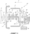
- the aircraft power plant 110 has a transmission 160 that includes first and second clutches 161, 162 each operable in an engaged configuration and a disengaged configuration.
- the transmission 160 may be operatively connected to the controller 40 to control operation of the first and second clutches 161, 162.
- the first and second clutches 161, 162 may be dog clutches, viscous clutches, and so on.
- the first clutch 161 has an input drivingly engaged to the HP shaft 25C and an output drivingly engaging a first gear 163A.
- the second clutch 162 has an input drivingly engaged to the LP shaft 24C and an output drivingly engaging a second gear 163B.
- the first and second gears 163A, 163B are meshed with a third gear 163C, which is drivingly engaged to the electrical machine 50 via an output shaft 164 of the transmission 160.
- one or both of the first and second clutches 161, 162 may be in its engaged configuration to provide a rotational input to the electrical machine 50.
- the transmission 160 may be limited to having only one of the two spools 24, 25 engaged to the electrical machine 50 at a time.
- the transmissions 60, 160 described herein may allow higher power extraction for a single generator and may void the possible addition of a second generator.
- the method 400 includes receiving a signal from at least one sensor 41 ( Fig. 1 ), the signal indicative of an operating condition of the aircraft power plant at 402.
- the method 400 includes determining a portion of a torque requirement of the electrical machine 50 to be provided by one of the high-pressure spool 25 and the low-pressure spool 24 as a function of the operating condition of the aircraft power plant at 404.
- the method 400 then includes transmitting the portion of the torque requirement from the one of the high-pressure spool 25 and the low-pressure spool 24 to the electrical machine 50 and transmitting a remainder of the torque requirement from the other of the high-pressure spool 25 and the low-pressure spool 24 to the electrical machine 50.
- the remainder of the torque requirement may be zero such that all of the torque requirement is to be fulfilled by only one of the two spools 24, 25.
- the determining that the portion of the torque requirement of the electrical machine 50 to be provided by the one of the high-pressure spool 25 and the low-pressure spool 24 may include: determining that an entirety of the torque requirement is to be provided to the electrical machine 50 by the one of the high-pressure spool 25 and the low-pressure spool 24; and drivingly engaging the electrical machine 50 to the one of the high-pressure spool 25 and the low-pressure spool 24 while the other of the high-pressure spool 25 and the low-pressure spool 24 is disengaged from the electrical machine 50.
- the determining that the portion of the torque requirement of the electrical machine to be provided by the one of the high-pressure spool 25 and the low-pressure spool 24 may include: determining that the torque requirement is to be provided to the electrical machine 50 by both of the high-pressure spool 25 and the low-pressure spool 24; and drivingly engaging both of the high-pressure spool 25 and the low-pressure spool 24 to the electrical machine 50. This may be done by drivingly engaging the high-pressure spool 25 to the electrical machine 50 via the first coupling device 61; and drivingly engaging the low-pressure spool 24 to the electrical machine 50 via the second coupling device 62.
- one or both of the first coupling device 61 and the second coupling device 62 may have at least one intermediary configuration in which an input of the one or both of the first coupling device 61 and the second coupling device 62 rotates at a different speed than an output of the one or both of the first coupling device 61 and the second coupling device 62.
- the signal may be indicative of an altitude of the aircraft power plant 10.
- the method 400 may include: determining that the altitude is below an altitude threshold; and determining that no torque is to be provided by the low-pressure spool 24.
- the method 400 may include determining that the altitude is above an altitude threshold; and determining that no torque is to be provided by the high-pressure spool 25.
- the method 400 may include determining an optimal configuration corresponding to one of the first, second, and hybrid configurations of the transmission 60 based on the received signal; and operating the transmission 60 in the determined optimal configuration.
- the signal may be indicative of an altitude of the aircraft power plant 10 and the determining of the optimal configuration includes determining that the altitude is below an altitude threshold and the operating of the transmission may include operating the transmission in the first configuration in which in which the transmission 60 drivingly engages the first input 60A to the output 60C while the second input 60B is disengaged from the output 60C and in which the LP shaft 24C is disengaged from the electrical machine 50.
- the determining of the optimal configuration may include determining that the altitude is above an altitude threshold and the operating of the transmission includes operating the transmission in the second configuration in which in which the transmission 60 drivingly engages the second input 60B to the output 60C while the first input 60A is disengaged from the output 60C and in which the HP shaft 25C is disengaged from the electrical machine 50.
- the signal indicative of the altitude may be provided by the sensor 41, which may be a total temperature sensor, a temperature sensor, an altimeter, a total pressure sensor, and/or a pressure sensor. Other parameters may be used to determine which of the two spools is to drive the electrical machine 50.
- An engine inlet temperature signal from a temperature sensor can be used in conjunction with the aforementioned pressure signal.
- a compressor discharge / combustor cavity pressure (P3) signal could also be used in conjunction with engine rotating speed sensor and other engine temperature and pressure sensors as an indication of compressor surge margin status and could drive a change in the spool driving the electrical machine 50.
- the determining of the optimal configuration includes: determining that the optimal configuration corresponds to the hybrid configuration.
- the method 400 may then include determining an optimal power split between the high-pressure shaft 25C and the low-pressure shaft 24C as a function of the operating condition of the aircraft power plant 10; and driving the electrical machine 50 per the determined optimal power split.
- the determining of the optimal power split includes determining the optimal power split from a look-up table stored in a computer-readable medium of the controller 40.
- the power split may, for instance, require that torque requirement of the electrical machine 50 be divided in half between the two spools 24, 25. Hence, 50% of the torque requirement may be provided by the HP spool 25 and 50% of the torque requirement may be provided by the LP spool 24. In some cases, a 70/30 split is desirable.
- the controller 40 may be able to compute the optimal power split.
- a total torque of the two spools 24, 25 may be greater than the torque requirement of the electrical machine 50.
- the first and second coupling devices 61, 62 may suitably reduce the torque they receive from the respective spools 24, 25 to ensure that the proper torque is provided to the electrical machine 50.
- the controller 40 may control the first and second coupling devices 61, 62 to adjust or modulate the torque that is transmitted from the spools 24, 25 to the output 60C of the transmission 60. This may include controlling a dimension of the gaps, and hence a thickness of the films 61C, 62C by powering the actuators 61D, 62D.
- the controller 40 may be implemented with one or more computing devices 500.
- the controller 40 can be implemented as part of a full-authority digital engine controls (FADEC) or other similar device, including electronic engine control (EEC), engine control unit (ECU), electronic propeller control, propeller control unit, and the like.
- FADEC full-authority digital engine controls
- EEC electronic engine control
- ECU engine control unit
- propeller control propeller control unit
- the controller 40 is implemented as a Flight Data Acquisition Storage and Transmission system, such as a FAST TM system.
- the controller 40 may be implemented in part in the FAST TM system and in part in the EEC. Other embodiments may also apply.
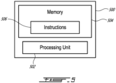
- the computing device 500 comprises a processing unit 502 and a memory 504 which has stored therein computer-executable instructions 506.
- the processing unit 502 may comprise any suitable devices configured to implement the method 400 such that instructions 506, when executed by the computing device 500 or other programmable apparatus, may cause the functions/acts/steps performed as part of the method 400 as described herein to be executed.
- the processing unit 502 may comprise, for example, any type of general-purpose microprocessor or microcontroller, a digital signal processing (DSP) processor, a central processing unit (CPU), an integrated circuit, a field programmable gate array (FPGA), a reconfigurable processor, other suitably programmed or programmable logic circuits, or any combination thereof.
- DSP digital signal processing
- CPU central processing unit
- FPGA field programmable gate array
- reconfigurable processor other suitably programmed or programmable logic circuits, or any combination thereof.
- the memory 504 may comprise any suitable known or other machine-readable storage medium.
- the memory 504 may comprise non-transitory computer readable storage medium, for example, but not limited to, an electronic, magnetic, optical, electromagnetic, infrared, or semiconductor system, apparatus, or device, or any suitable combination of the foregoing.
- the memory 504 may include a suitable combination of any type of computer memory that is located either internally or externally to device, for example random-access memory (RAM), read-only memory (ROM), compact disc read-only memory (CDROM), electro-optical memory, magneto-optical memory, erasable programmable read-only memory (EPROM), and electrically-erasable programmable read-only memory (EEPROM), Ferroelectric RAM (FRAM) or the like.
- Memory 504 may comprise any storage means (e.g., devices) suitable for retrievably storing machine-readable instructions 506 executable by processing unit 502.
- the methods and systems for driving an electrical machine described herein may be implemented in a high level procedural or object oriented programming or scripting language, or a combination thereof, to communicate with or assist in the operation of a computer system, for example the computing device 500.
- the methods and systems for driving an electrical machine may be implemented in assembly or machine language.
- the language may be a compiled or interpreted language.
- Program code for implementing the methods and systems for driving an electrical machine may be stored on a storage media or a device, for example a ROM, a magnetic disk, an optical disc, a flash drive, or any other suitable storage media or device.
- the program code may be readable by a general or special-purpose programmable computer for configuring and operating the computer when the storage media or device is read by the computer to perform the procedures described herein.
- Embodiments of the methods and systems for driving an electrical machine may also be considered to be implemented by way of a non-transitory computer-readable storage medium having a computer program stored thereon.
- the computer program may comprise computer-readable instructions which cause a computer, or more specifically the processing unit 502 of the computing device 500, to operate in a specific and predefined manner to perform the functions described herein, for example those described in the method 400.
- Computer-executable instructions may be in many forms, including program modules, executed by one or more computers or other devices.
- program modules include routines, programs, objects, components, data structures, etc., that perform particular tasks or implement particular abstract data types.
- functionality of the program modules may be combined or distributed as desired in various embodiments.
- the embodiments described herein are implemented by physical computer hardware, including computing devices, servers, receivers, transmitters, processors, memory, displays, and networks.
- the embodiments described herein provide useful physical machines and particularly configured computer hardware arrangements.
- the embodiments described herein are directed to electronic machines and methods implemented by electronic machines adapted for processing and transforming electromagnetic signals which represent various types of information.
- the embodiments described herein pervasively and integrally relate to machines, and their uses; and the embodiments described herein have no meaning or practical applicability outside their use with computer hardware, machines, and various hardware components. Substituting the physical hardware particularly configured to implement various acts for non-physical hardware, using mental steps for example, may substantially affect the way the embodiments work.
- connection or “coupled to” may include both direct coupling (in which two elements that are coupled to each other contact each other) and indirect coupling (in which at least one additional element is located between the two elements).
- the technical solution of embodiments may be in the form of a software product.
- the software product may be stored in a non-volatile or non-transitory storage medium, which can be a compact disk read-only memory (CD-ROM), a USB flash disk, or a removable hard disk.
- the software product includes a number of instructions that enable a computer device (personal computer, server, or network device) to execute the methods provided by the embodiments.
Landscapes
- Engineering & Computer Science (AREA)
- Mechanical Engineering (AREA)
- General Engineering & Computer Science (AREA)
- Chemical & Material Sciences (AREA)
- Combustion & Propulsion (AREA)
- Aviation & Aerospace Engineering (AREA)
- Connection Of Motors, Electrical Generators, Mechanical Devices, And The Like (AREA)
Abstract
Description
- The application relates generally to aircraft engines and, more particularly, to gearboxes and transmissions used to drive accessories connected to aircraft engines.
- Aircraft engines, such as gas turbine engines, may have two spools, namely a low-pressure spool and a high-pressure spool, which are independently rotatable from one another. Accessories, such as generators for example, are typically driven by the high-pressure spool. In some operating conditions, the power extracted by the accessory driven by the high-pressure spool may be limited. Hence, improvements are sought.
- In one aspect, there is provided an aircraft power plant comprising: a high-pressure spool including a high-pressure compressor, a high-pressure turbine, and a high-pressure shaft drivingly engaging the high-pressure turbine to the high-pressure compressor; a low-pressure spool including a low-pressure compressor, a low-pressure turbine, and a low-pressure shaft drivingly engaging the low-pressure turbine to the low-pressure compressor; an electrical machine operable as a generator; and a transmission having a first input drivingly engaged by the high-pressure shaft, a second input drivingly engaged by the low-pressure shaft, and an output drivingly engaging the electrical machine, the transmission having a coupling system selectively interconnecting the output with one of: the first input, with the second input disconnected from the output; the second input, with the first input disconnected from the output; and both of the first input and the second input.
- The aircraft power plant as defined above and described elsewhere herein may also include one or more of the following features, in whole or in part, and in any combination.
- In some embodiments, the coupling system includes: a first coupling device having a first engaged configuration and a first disengaged configuration, the first input engaged to the output via the first coupling device in the first engaged configuration and disengaged from the output in the first disengaged configuration, and a second coupling device having a second engaged configuration and a second disengaged configuration, the second input engaged to the output via the second coupling device in the second engaged configuration and disengaged from the output in the second disengaged configuration.
- In some embodiments, one or both of the first coupling device and the second coupling device has at least one intermediary configuration in which an input of the one or both of the first coupling device and the second coupling device rotates at a different speed than an output of the one or both of the first coupling device and the second coupling device.
- In some embodiments, the one or both of the first coupling device and the second coupling device is a viscous coupling device having two members rotatable one relative to the other, the two members spaced apart from one another by a gap filled with a fluid.
- In some embodiments, an actuator is engaged to one of the two members, the actuator operable to move the one of the two members toward and away from the other of the two members to vary a dimension of the gap.
- In some embodiments, the transmission includes: a first load path from the first input to the output via the first coupling device, the first load path including a first gear engaged to a first coupling input of the first coupling device, and a second gear engaging the output and engaged by a first coupling output of the first coupling device, and a second load path from the second input to the output via the second coupling device, the second load path including a third gear engaged to a second coupling input of the second coupling device, and the second gear engaging the output and engaged by a second coupling output of the second coupling device.
- In some embodiments, the first coupling input is defined by a fourth gear meshed with the first gear, the first coupling output defined by a fifth gear meshed with the second gear, the fourth gear engaged to the fifth gear via a fluid received within a first gap defined between the fourth gear and the fifth gear, the second coupling input is defined by a sixth gear meshed with the third gear, the second coupling output defined by a seventh gear meshed with the second gear, the sixth gear engaged to the seventh gear via a fluid received within a second gap defined between the sixth gear and the seventh gear.
- In some embodiments, the coupling system interconnects the output with the first input when an altitude of the aircraft power plant is below an altitude threshold.
- In some embodiments, the coupling system interconnects the output with the second input when an altitude of the aircraft power plant is above an altitude threshold.
- In some embodiments, a controller has a processing unit operatively connected to a computer-readable medium having instructions stored thereon executable by the processing unit for: receiving a signal from at least one sensor, the signal indicative of an operating condition of the aircraft power plant; based on the received signal, determining a configuration of the transmission, the configuration being one of: a first configuration in which the transmission drivingly engages the first input to the output while the second input is disengaged from the output, a second configuration in which the transmission drivingly engages the second input to the output while the first input is disengaged from the output, and a hybrid configuration in which both of the first input and the second input are drivingly engaged to the output through the transmission; and operating the transmission in the determined configuration.
- In some embodiments, the signal is indicative of an altitude of the aircraft power plant, the determining of the configuration includes determining that the altitude is below an altitude threshold and the operating of the transmission includes operating the transmission in the first configuration.
- In some embodiments, the signal is indicative of an altitude of the aircraft power plant, the determining of the configuration includes determining that the altitude is above an altitude threshold and the operating of the transmission includes operating the transmission in the second configuration.
- In some embodiments, the determining of the configuration includes: determining that the configuration corresponds to the hybrid configuration; determining a power split between the high-pressure shaft and the low-pressure shaft as a function of the operating condition of the aircraft power plant; and driving the electrical machine per the determined power split.
- In some embodiments, the determining of the power split includes determining the power split from a look-up table stored in the computer-readable medium.
- In another aspect, there is provided a method of driving an electrical machine with an aircraft power plant having a high-pressure spool and a low-pressure spool, the method comprising: receiving a signal from at least one sensor, the signal indicative of an operating condition of the aircraft power plant; determining a portion of a torque requirement of the electrical machine to be provided by one of the high-pressure spool and the low-pressure spool as a function of the operating condition of the aircraft power plant; and transmitting the portion of the torque requirement from the one of the high-pressure spool and the low-pressure spool to the electrical machine and transmitting a remainder of the torque requirement from the other of the high-pressure spool and the low-pressure spool to the electrical machine.
- The method as defined above and described elsewhere herein may also include one or more of the following steps and/or features, in whole or in part, and in any combination.
- In some embodiments, the determining that the portion of the torque requirement of the electrical machine to be provided by the one of the high-pressure spool and the low-pressure spool includes: determining that an entirety of the torque requirement is to be provided to the electrical machine by the one of the high-pressure spool and the low-pressure spool; and drivingly engaging the electrical machine to the one of the high-pressure spool and the low-pressure spool while the other of the high-pressure spool and the low-pressure spool is disengaged from the electrical machine.
- In some embodiments, the determining that the portion of the torque requirement of the electrical machine to be provided by the one of the high-pressure spool and the low-pressure spool includes: determining that the torque requirement is to be provided to the electrical machine by both of the high-pressure spool and the low-pressure spool; and drivingly engaging both of the high-pressure spool and the low-pressure spool to the electrical machine.
- In some embodiments, the drivingly engaging of both of the high-pressure spool and the low-pressure spool to the electrical machine includes: drivingly engaging the high-pressure spool to the electrical machine via a first coupling device; and drivingly engaging the low-pressure spool to the electrical machine via a second coupling device, wherein one or both of the first coupling device and the second coupling device has at least one intermediary configuration in which an input of the one or both of the first coupling device and the second coupling device rotates at a different speed than an output of the one or both of the first coupling device and the second coupling device.
- In some embodiments, the signal is indicative of an altitude of the aircraft power plant, the determining of the portion of a torque requirement of the electrical machine to be provided by one of the high-pressure spool and the low-pressure spool as a function of the operating condition of the aircraft power plant includes: determining that the altitude is below an altitude threshold; and determining that no torque is to be provided by the low-pressure spool.
- In some embodiments, the signal is indicative of an altitude of the aircraft power plant, the determining of the portion of a torque requirement of the electrical machine to be provided by one of the high-pressure spool and the low-pressure spool as a function of the operating condition of the aircraft power plant includes: determining that the altitude is above an altitude threshold; and determining that no torque is to be provided by the high-pressure spool.
- Reference is now made to the accompanying figures in which:
-
Fig. 1 is a schematic cross-sectional view of an aircraft power plant depicted as a turboprop gas turbine engine in accordance with one embodiment; -
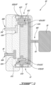
Fig. 2 is an enlarged view of a portion ofFig. 1 illustrating a transmission of the aircraft power plant ofFig. 1 ; -
Fig. 3 is a schematic cross-sectional view of an aircraft power plant depicted as a turboprop gas turbine engine in accordance with another embodiment; -
Fig. 4 is a flowchart illustrating steps of a method of operating the power plants ofFigs. 1 and2 ; and -
Fig. 5 is a schematic representation of a controller in accordance with one embodiment. - In at least some of the figures that follow, some elements appear more than once (e.g. there may be two, three, etc. of a given part in a given embodiment). Accordingly, only a first instance of each given element may be labeled, to maintain clarity of the figures.
- Referring to
Fig. 1 , an aircraft power plant is shown at 10. Theaircraft power plant 10 is referred to herein below simply as "power plant 10" for the sake of conciseness. Thepower plant 10 includes agas turbine engine 11. Thegas turbine engine 11 is shown inFig. 1 as being a turboprop gas turbine engine drivingly engaged to apropeller 12 via areduction gearbox 14. It will be appreciated that the principles of the present disclosure may apply to any engine having two spools as will be explained below. These engines may include, for instance, turbofan and turboshaft. - The
gas turbine engine 11 includes aninlet 21 at a rear of thegas turbine engine 11 relative to a direction of travel T of thepower plant 10. Thegas turbine engine 11 includes anexhaust 22 at a front of thepower plant 10 relative to the direction of travel T. Thegas turbine engine 11 is therefore a reverse-flow engine in that air flows from theinlet 21 to theexhaust 22 in anannular gas path 23 from the rear to the front in the same direction as the direction of travel T. - The
gas turbine engine 11 includes a low-pressure (LP)spool 24 and a high-pressure (HP)spool 25. The term "spool" is herein intended to broadly refer to drivingly connected turbine and compressor rotors and is, thus, not limited to a compressor and turbine assembly on a single shaft. It also includes a rotary assembly with multiple shafts geared together. TheLP spool 24 includes aLP compressor 24A, a LP orpower turbine 24B, and aLP shaft 24C drivingly engaging theLP turbine 24B to theLP compressor 24A. The HP spool 25 includes a HPcompressor 25A, a HPturbine 25B, and a HPshaft 25C drivingly engaging the HPturbine 25B to the HPcompressor 25A. Thegas turbine engine 11 includes acombustor 26 between the HPturbine 25B and the HPcompressor 25A. In the embodiment shown, the HPshaft 25C is hollow and theLP shaft 24C extends within the HPshaft 25C. Other configurations are contemplated. - In use, air enters the
gas turbine engine 11 via theinlet 21 and flows into theannular gas path 23 through theLP compressor 24A and through the HPcompressor 25A located downstream of theLP compressor 24A relative to a direction of the flow into theannular gas path 23. The air, now compressed, is mixed with fuel into thecombustor 26 and is ignited thereby generating combustion gases. The combustion gases flow out of thecombustor 26 into the HPturbine 25B, which extracts energy from the combustion gases to drive the HPcompressor 25A via the HPshaft 25C. The combustion gases then flow through the LP orpower turbine 24B located downstream of the HPturbine 25B relative to the direction of the flow through theannular gas path 23. TheLP turbine 24B extracts power from the combustion gases to drive theLP compressor 24A via theLP shaft 24C. TheLP turbine 24B further drivingly engages thepropeller 12 via thereduction gearbox 14. Thereduction gearbox 14 drives thepropeller 12 via anoutput shaft 27. - In the embodiment shown, the
gas turbine engine 11 includes variable inlet guide vanes (VIGV) 30 located upstream of theLP compressor 24A relative to the flow in theannular gas path 23. TheVIGV 30 includesairfoils 31 that are each pivotable about respective spanwise axes to orient the incoming flow from theinlet 21 toward theLP compressor 24A. In the present embodiment, theairfoils 31 extend in a direction being substantially axial relative to a central axis of thegas turbine engine 11. In some embodiments, theairfoils 31 may extend in a direction having a radial component relative to the central axis of thegas turbine engine 11. TheVIGV 30 is operatively connected to acontroller 40 of theaircraft power plant 10; thecontroller 40 operable to vary angles of attack defined between the incoming flow and theairfoils 31. - Still referring to
Fig. 1 , theaircraft power plant 10 is used to drive an accessory such as anelectrical machine 50. Typically, theelectrical machine 50 is driven solely by theHP spool 25. Theelectrical machine 50 may be used in an electric motor configuration to drive theHP spool 25 for starting thegas turbine engine 11. Theelectrical machine 50 may be used in a generator configuration to generate electrical power to be used by an aircraft equipped with theaircraft power plant 10. - It was observed that, when the
electrical machine 50 is being used in the generator configuration, the power extracted by theelectrical machine 50 driven by theHP spool 25 may be limited for operability reasons. For instance, higher loads on theHP compressor 25A may reduce its surge margin, which may be undesirable. Typically, when this situation occurs, a second generator driven by theLP spool 24 is being used. However, this adds complexity and weight to thepower plant 10, which may be undesirable. - In the embodiment shown, the
aircraft power plant 10 includes atransmission 60, which may also be referred to as a differential, used to transmit a rotational input from both of theHP shaft 25C and theLP shaft 24C to theelectrical machine 50. Hence, if power extraction requirement for certain engine operating conditions makes theHP compressor 25A surge margin fall below the operability threshold, thetransmission 60 is used to transmit power from theLP spool 24 to theelectrical machine 50 used in the generator mode. Hence, the use of a second generator may be avoided. - In the embodiment shown, series of
intermediary shafts 49 are used to connect thetransmission 60 to theHP shaft 25C. It will be understood that any suitable connection may be used to drivingly engage thetransmission 60 to theHP shaft 25. Theintermediary shafts 49 may be drivingly engaged to one another using bevel gears, universal joints, or any other suitable means. One of theintermediary shafts 49 is located radially outside theannular gas path 23 relative to an axis of rotation of the HP andLP shafts intermediary shafts 49 are shown as being connected at a rear of theHP shaft 25C, they may alternatively be connected at a front thereof. In the present case, thetransmission 60 is driven by theLP shaft 24C directly. However, it will be understood that intermediary shaft may be used to connect theLP shaft 24C to thetransmission 60. - Referring now to
Fig. 2 , thetransmission 60 is described in more detail. Thetransmission 60 has afirst input 60A drivingly engaged by theHP shaft 25C, herein via theintermediary shafts 49. Thetransmission 60 has asecond input 60B drivingly engaged by theLP shaft 24C. Thetransmission 60 has anoutput 60C drivingly engaging theelectrical machine 50. Thetransmission 60 is operable in a plurality of configurations to select which of the LP and HP spools 24, 25, or a combination thereof, drives theelectrical machine 50 as a function of operating conditions of thepower plant 10. Thetransmission 60 includes a coupling system, which will be described below. The coupling system is used to selectively interconnect theoutput 60C with one of: thefirst input 60A, with thesecond input 60B disconnected from theoutput 60C; thesecond input 60B, with thefirst input 60A disconnected from theoutput 60C; and both of thefirst input 60A and thesecond input 60B. - The
transmission 60 has a first configuration in which thetransmission 60 drivingly engages thefirst input 60A to theoutput 60C while thesecond input 60B is disengaged from theoutput 60C. In the first configuration, solely theHP shaft 25C drives theelectrical machine 50 and theLP shaft 24C is disengaged from theelectrical machine 50. Hence, no power is extracted from theLP shaft 24C in the first configuration of thetransmission 60. In some operating conditions, thegas turbine engine 11 may benefit from having higher loads extracted from theHP spool 25. For instance, at low altitude take-off during a hot day, higher loads on theHP spool 25 may reduce its rotational speed, which may avoid theHP spool 25 from reaching its speed limit. Hence, during these operating conditions, theLP spool 24 may be disengaged from theelectrical machine 50 to maximize the load on theHP spool 25. During starting of thegas turbine engine 11, theelectrical machine 50 is operated as an electrical motor and is coupled solely to theHP shaft 25C to accelerate theHP spool 25. Hence, during engine start-up, theLP spool 24 may be disengaged from theelectrical machine 50. - The
transmission 60 has a second configuration in which thetransmission 60 drivingly engages thesecond input 60B to theoutput 60C while thefirst input 60A is disengaged from theoutput 60C. In the second configuration, solely theLP shaft 24C drives theelectrical machine 50 and theHP shaft 25C is disengaged from theelectrical machine 50. Hence, no power is extracted from theHP shaft 25C in the second configuration of thetransmission 60. In certain operating conditions, theLP shaft 24C of thegas turbine engine 11 may have a fixed rotating speed that may benefit from having higher loads on theLP compressor 24C connected thereto. For instance, at high altitude during cruise, higher loading on theLP compressor 24C may result in the opening of theVIGV 30, which may allow more air mass flow in thegas turbine engine 11. This may result in thegas turbine engine 11 having higher output power capability. In such operating condition, theHP spool 25 may be decoupled from theelectrical machine 50, leaving the entire load to theLP spool 24 to maximize engine available power and spare the surge margin of theHP compressor 25A. In these operating conditions, theLP compressor 24A may be less sensitive surge-margin-wise than theHP compressor 25A to accessory power extraction. That is, more power can be extracted from theLP spool 24 before the surge margin of theLP compressor 24A is affected as much as the surge margin of theHP compressor 25A would be for the same power extraction by theelectrical machine 50. - The
transmission 60 may have a hybrid configuration in which both of thefirst input 60A and thesecond input 60B are drivingly engaged to theoutput 60C through thetransmission 60. In this hybrid configuration, both of the LP and HP spools 24, 25 provide power to theelectrical machine 50. The hybrid configuration may be used to smoothly switch between the first and second configurations. This may allow thegas turbine engine 11 to run optimally from performance and operability standpoints. During engine operation, thecontroller 40 may receive data about engine inlet total pressure and total temperature and, from the received data, may determine an optimal split between the power extracted from the LP and HP spools 24, 25 to drive theelectrical machine 50. When the total pressure and total temperature are above respective thresholds, more power may be extracted from theHP spool 25 than from theLP spool 24. When the total pressure and total temperature are below respective thresholds, more power may be extracted from theLP spool 24 than from theHP spool 25. - The
electrical machine 50 may have a torque requirement for proper operation at a given operating condition. For instance, the torque requirement of theelectrical machine 50 may be dictated by a power output required from theelectrical machine 50 when operated as a generator. Thetransmission 60 may allow one or both of the HP and LP spools 25, 24 to fulfill the torque requirement of theelectrical machine 50. - The
transmission 60 may further be able to provide adequate speed ratios to cater to the difference between the rotational speeds of the HP and LP spools 25, 24 and the desired rotating speed of theelectrical machine 50. Gears of varying diameters may be used for that purpose as will be described below. - Still referring to
Fig. 2 , the coupling system of thetransmission 60 includes afirst coupling device 61 and asecond coupling device 62. Thefirst coupling device 61 is used to transmit a rotational input from theHP shaft 25C to theelectrical machine 50. Thefirst coupling device 61 has a first engaged configuration and a first disengaged configuration. Thefirst input 60A of thetransmission 60 is engaged to theoutput 60C of thetransmission 60 via thefirst coupling device 61 in the first engaged configuration and disengaged from theoutput 60C in the first disengaged configuration. Similarly, thesecond coupling device 62 having a second engaged configuration and a second disengaged configuration. Thesecond input 60B of thetransmission 60 is engaged to theoutput 60C of thetransmission 60 via thesecond coupling device 62 in the second engaged configuration and disengaged from theoutput 60C in the second disengaged configuration. - The
first coupling device 61 has afirst coupling input 61A drivingly engaged by thefirst input 60A of thetransmission 60, and has afirst coupling output 61B drivingly engaging theoutput 60C of thetransmission 60. Similarly, thesecond coupling device 62 has asecond coupling input 62A drivingly engaged by thesecond input 60B of thetransmission 60, and has asecond coupling output 62B drivingly engaging theoutput 60C of thetransmission 60. Thefirst coupling input 61A is engaged to thefirst coupling output 61B in the first engaged configuration and disengaged from thefirst coupling output 61B in the first disengaged configuration. Thesecond coupling input 62A is engaged to thesecond coupling output 62B in the second engaged configuration and disengaged from thesecond coupling output 62B in the second disengaged configuration. - The first and
second coupling devices second coupling devices second coupling inputs second coupling outputs first coupling input 61A and thesecond coupling input 62A may rotate while no torque is transferred to thefirst coupling output 61B and thesecond coupling output 62B. In the first and second engaged configurations, thefirst coupling input 61A may rotate at the same speed as thefirst coupling output 61B and thesecond coupling input 62A may rotate at the same speed as thesecond coupling output 62B. In the embodiment shown, the first andsecond coupling devices first coupling input 61A rotates at a different speed than thefirst coupling output 61A and in which thesecond coupling input 62A rotates at a different speed than thesecond coupling output 62B. In some embodiments, only one of the first andsecond coupling devices electrical machine 50 with both of the HP and LP spools 25, 24 while avoiding the HP spool from being engaged to the LP spool, which would make the gas turbine engine 11 a single-spool engine, which may be undesirable in some operating conditions. However, in some other configurations, performance benefits may be achieved. - In the intermediate configuration of the
first coupling device 61, a torque is transferred from thefirst coupling input 61A to thefirst coupling output 61B, but the transferred torque may be less than a torque received at thefirst coupling input 61A from theHP shaft 25C. Similarly, in the intermediate configuration of thesecond coupling device 62, a torque is transferred from thesecond coupling input 62A to thesecond coupling output 62B, but the transferred torque may be less than a torque received at thesecond coupling input 62A from theLP shaft 24C. Hence, the first andsecond coupling devices LP shafts second coupling devices electrical machine 50 while extracting the most optimal power from the HP andLP shafts - As shown in
Fig. 2 , thetransmission 60 includes afirst driving gear 63A drivingly engaged by theHP shaft 25C and asecond driving gear 63B drivingly engaged by theLP shaft 24C. Thefirst driving gear 63A is meshed with afirst idler gear 63C that defines thefirst coupling input 61A of thefirst coupling device 61. Thesecond driving gear 63B is meshed with asecond idler gear 63D that defines thesecond coupling input 62A of thesecond coupling device 62. Thefirst coupling output 61B is defined by athird idler gear 63E and thesecond coupling output 62B is defined by afourth idler gear 63F. - The
first idler gear 63C is drivingly engageable to thethird idler gear 63E via afilm 61C of a fluid located within a gap between thefirst idler gear 63C and thethird idler gear 63E. Similarly, thesecond idler gear 63D is drivingly engageable to thefourth idler gear 63F via afilm 62C of a fluid located within a gap between thesecond idler gear 63D and thefourth idler gear 63F. Thefilms first idler gear 63C and thethird idler gear 63E and between thesecond idler gear 63D and thefourth idler gear 63F may be varied with first andsecond actuators - The
actuators controller 40 to vary the distances between the gears. The torque is transferred via shearing stress of the viscous fluid located within the gaps between the gears. The smaller the distance, the greater the torque transferred via the first andsecond coupling devices - Both of the third and fourth idler gears 63E, 63F are meshed with a driven
gear 63G that is drivingly engaged to theelectrical machine 50 via anoutput shaft 64 of thetransmission 60. Hence, the power extracted from the HP andLP shafts gear 63G to drive theelectrical machine 50. In the present embodiment, all of the gears are depicted as bevel gears. It will be appreciated that other configurations are contemplated without departing from the scope of the present disclosure. The diameters of the gears is selected to provide required speed ratios between the HP andLP shafts output shaft 64 of thetransmission 60. - The
transmission 60 therefore includes a first load path and a second load path. The first load path extends from thefirst input 60A to theoutput 60C via thefirst coupling device 61. The first load path includes thefirst driving gear 63A engaged to thefirst coupling input 61A of thefirst coupling device 61 and the drivengear 63G engaging theoutput 60C of thetransmission 60 and engaged by thefirst coupling output 61B of thefirst coupling device 61. - The second load path extends from the
second input 60B of thetransmission 60 to theoutput 60C via thesecond coupling device 62. The second load path includes thesecond driving gear 63B engaged to thesecond coupling input 62A of thesecond coupling device 62, and the drivengear 63G engaging theoutput 60C and engaged by thesecond coupling output 62B of thesecond coupling device 62. - Referring now to
Fig. 3 , another embodiment of an aircraft power plant is shown at 110. For the sake of conciseness, only elements that differ from theaircraft power plant 10 described above are described below. - The
aircraft power plant 110 has atransmission 160 that includes first andsecond clutches transmission 160 may be operatively connected to thecontroller 40 to control operation of the first andsecond clutches second clutches first clutch 161 has an input drivingly engaged to theHP shaft 25C and an output drivingly engaging afirst gear 163A. Thesecond clutch 162 has an input drivingly engaged to theLP shaft 24C and an output drivingly engaging asecond gear 163B. The first andsecond gears third gear 163C, which is drivingly engaged to theelectrical machine 50 via anoutput shaft 164 of thetransmission 160. In use one or both of the first andsecond clutches electrical machine 50. Thetransmission 160 may be limited to having only one of the twospools electrical machine 50 at a time. - The
transmissions - Referring now to
Fig. 4 , a method of driving the electrical machine is shown at 400. Themethod 400 includes receiving a signal from at least one sensor 41 (Fig. 1 ), the signal indicative of an operating condition of the aircraft power plant at 402. Themethod 400 includes determining a portion of a torque requirement of theelectrical machine 50 to be provided by one of the high-pressure spool 25 and the low-pressure spool 24 as a function of the operating condition of the aircraft power plant at 404. Themethod 400 then includes transmitting the portion of the torque requirement from the one of the high-pressure spool 25 and the low-pressure spool 24 to theelectrical machine 50 and transmitting a remainder of the torque requirement from the other of the high-pressure spool 25 and the low-pressure spool 24 to theelectrical machine 50. In some embodiments, the remainder of the torque requirement may be zero such that all of the torque requirement is to be fulfilled by only one of the twospools - In the embodiment shown, the determining that the portion of the torque requirement of the
electrical machine 50 to be provided by the one of the high-pressure spool 25 and the low-pressure spool 24 may include: determining that an entirety of the torque requirement is to be provided to theelectrical machine 50 by the one of the high-pressure spool 25 and the low-pressure spool 24; and drivingly engaging theelectrical machine 50 to the one of the high-pressure spool 25 and the low-pressure spool 24 while the other of the high-pressure spool 25 and the low-pressure spool 24 is disengaged from theelectrical machine 50. - The determining that the portion of the torque requirement of the electrical machine to be provided by the one of the high-
pressure spool 25 and the low-pressure spool 24 may include: determining that the torque requirement is to be provided to theelectrical machine 50 by both of the high-pressure spool 25 and the low-pressure spool 24; and drivingly engaging both of the high-pressure spool 25 and the low-pressure spool 24 to theelectrical machine 50. This may be done by drivingly engaging the high-pressure spool 25 to theelectrical machine 50 via thefirst coupling device 61; and drivingly engaging the low-pressure spool 24 to theelectrical machine 50 via thesecond coupling device 62. As explained above, one or both of thefirst coupling device 61 and thesecond coupling device 62 may have at least one intermediary configuration in which an input of the one or both of thefirst coupling device 61 and thesecond coupling device 62 rotates at a different speed than an output of the one or both of thefirst coupling device 61 and thesecond coupling device 62. - The signal may be indicative of an altitude of the
aircraft power plant 10. In such a case, themethod 400 may include: determining that the altitude is below an altitude threshold; and determining that no torque is to be provided by the low-pressure spool 24. Or, themethod 400 may include determining that the altitude is above an altitude threshold; and determining that no torque is to be provided by the high-pressure spool 25. - The
method 400 may include determining an optimal configuration corresponding to one of the first, second, and hybrid configurations of thetransmission 60 based on the received signal; and operating thetransmission 60 in the determined optimal configuration. In some cases, the signal may be indicative of an altitude of theaircraft power plant 10 and the determining of the optimal configuration includes determining that the altitude is below an altitude threshold and the operating of the transmission may include operating the transmission in the first configuration in which in which thetransmission 60 drivingly engages thefirst input 60A to theoutput 60C while thesecond input 60B is disengaged from theoutput 60C and in which theLP shaft 24C is disengaged from theelectrical machine 50. In some cases, the determining of the optimal configuration may include determining that the altitude is above an altitude threshold and the operating of the transmission includes operating the transmission in the second configuration in which in which thetransmission 60 drivingly engages thesecond input 60B to theoutput 60C while thefirst input 60A is disengaged from theoutput 60C and in which theHP shaft 25C is disengaged from theelectrical machine 50. - The signal indicative of the altitude may be provided by the
sensor 41, which may be a total temperature sensor, a temperature sensor, an altimeter, a total pressure sensor, and/or a pressure sensor. Other parameters may be used to determine which of the two spools is to drive theelectrical machine 50. An engine inlet temperature signal from a temperature sensor can be used in conjunction with the aforementioned pressure signal. A compressor discharge / combustor cavity pressure (P3) signal could also be used in conjunction with engine rotating speed sensor and other engine temperature and pressure sensors as an indication of compressor surge margin status and could drive a change in the spool driving theelectrical machine 50. - In some other cases, the determining of the optimal configuration includes: determining that the optimal configuration corresponds to the hybrid configuration. The
method 400 may then include determining an optimal power split between the high-pressure shaft 25C and the low-pressure shaft 24C as a function of the operating condition of theaircraft power plant 10; and driving theelectrical machine 50 per the determined optimal power split. The determining of the optimal power split includes determining the optimal power split from a look-up table stored in a computer-readable medium of thecontroller 40. - The power split may, for instance, require that torque requirement of the
electrical machine 50 be divided in half between the twospools HP spool LP spool 24. In some cases, a 70/30 split is desirable. Thecontroller 40 may be able to compute the optimal power split. - It is understood that, in some cases, a total torque of the two
spools electrical machine 50. In this case, the first andsecond coupling devices respective spools electrical machine 50. Thecontroller 40 may control the first andsecond coupling devices spools output 60C of thetransmission 60. This may include controlling a dimension of the gaps, and hence a thickness of thefilms - With reference to
Fig. 5 , an example of acomputing device 500 is illustrated. For simplicity only onecomputing device 500 is shown but the system may includemore computing devices 500 operable to exchange data. Thecomputing devices 500 may be the same or different types of devices. Thecontroller 40 may be implemented with one ormore computing devices 500. Note that thecontroller 40 can be implemented as part of a full-authority digital engine controls (FADEC) or other similar device, including electronic engine control (EEC), engine control unit (ECU), electronic propeller control, propeller control unit, and the like. In some embodiments, thecontroller 40 is implemented as a Flight Data Acquisition Storage and Transmission system, such as a FAST™ system. Thecontroller 40 may be implemented in part in the FAST™ system and in part in the EEC. Other embodiments may also apply. - The
computing device 500 comprises aprocessing unit 502 and amemory 504 which has stored therein computer-executable instructions 506. Theprocessing unit 502 may comprise any suitable devices configured to implement themethod 400 such thatinstructions 506, when executed by thecomputing device 500 or other programmable apparatus, may cause the functions/acts/steps performed as part of themethod 400 as described herein to be executed. Theprocessing unit 502 may comprise, for example, any type of general-purpose microprocessor or microcontroller, a digital signal processing (DSP) processor, a central processing unit (CPU), an integrated circuit, a field programmable gate array (FPGA), a reconfigurable processor, other suitably programmed or programmable logic circuits, or any combination thereof. - The
memory 504 may comprise any suitable known or other machine-readable storage medium. Thememory 504 may comprise non-transitory computer readable storage medium, for example, but not limited to, an electronic, magnetic, optical, electromagnetic, infrared, or semiconductor system, apparatus, or device, or any suitable combination of the foregoing. Thememory 504 may include a suitable combination of any type of computer memory that is located either internally or externally to device, for example random-access memory (RAM), read-only memory (ROM), compact disc read-only memory (CDROM), electro-optical memory, magneto-optical memory, erasable programmable read-only memory (EPROM), and electrically-erasable programmable read-only memory (EEPROM), Ferroelectric RAM (FRAM) or the like.Memory 504 may comprise any storage means (e.g., devices) suitable for retrievably storing machine-readable instructions 506 executable by processingunit 502. - The methods and systems for driving an electrical machine described herein may be implemented in a high level procedural or object oriented programming or scripting language, or a combination thereof, to communicate with or assist in the operation of a computer system, for example the
computing device 500. Alternatively, the methods and systems for driving an electrical machine may be implemented in assembly or machine language. The language may be a compiled or interpreted language. Program code for implementing the methods and systems for driving an electrical machine may be stored on a storage media or a device, for example a ROM, a magnetic disk, an optical disc, a flash drive, or any other suitable storage media or device. The program code may be readable by a general or special-purpose programmable computer for configuring and operating the computer when the storage media or device is read by the computer to perform the procedures described herein. Embodiments of the methods and systems for driving an electrical machine may also be considered to be implemented by way of a non-transitory computer-readable storage medium having a computer program stored thereon. The computer program may comprise computer-readable instructions which cause a computer, or more specifically theprocessing unit 502 of thecomputing device 500, to operate in a specific and predefined manner to perform the functions described herein, for example those described in themethod 400. - Computer-executable instructions may be in many forms, including program modules, executed by one or more computers or other devices. Generally, program modules include routines, programs, objects, components, data structures, etc., that perform particular tasks or implement particular abstract data types. Typically the functionality of the program modules may be combined or distributed as desired in various embodiments.
- The embodiments described herein are implemented by physical computer hardware, including computing devices, servers, receivers, transmitters, processors, memory, displays, and networks. The embodiments described herein provide useful physical machines and particularly configured computer hardware arrangements. The embodiments described herein are directed to electronic machines and methods implemented by electronic machines adapted for processing and transforming electromagnetic signals which represent various types of information. The embodiments described herein pervasively and integrally relate to machines, and their uses; and the embodiments described herein have no meaning or practical applicability outside their use with computer hardware, machines, and various hardware components. Substituting the physical hardware particularly configured to implement various acts for non-physical hardware, using mental steps for example, may substantially affect the way the embodiments work. Such computer hardware limitations are clearly essential elements of the embodiments described herein, and they cannot be omitted or substituted for mental means without having a material effect on the operation and structure of the embodiments described herein. The computer hardware is essential to implement the various embodiments described herein and is not merely used to perform steps expeditiously and in an efficient manner.
- The term "connected" or "coupled to" may include both direct coupling (in which two elements that are coupled to each other contact each other) and indirect coupling (in which at least one additional element is located between the two elements).
- The technical solution of embodiments may be in the form of a software product. The software product may be stored in a non-volatile or non-transitory storage medium, which can be a compact disk read-only memory (CD-ROM), a USB flash disk, or a removable hard disk. The software product includes a number of instructions that enable a computer device (personal computer, server, or network device) to execute the methods provided by the embodiments.
- The embodiments described in this document provide non-limiting examples of possible implementations of the present technology. Upon review of the present disclosure, a person of ordinary skill in the art will recognize that changes may be made to the embodiments described herein without departing from the scope of the present technology. For example, the transmissions described herein may be used with any engine on which accessory load is extracted from more than one spool. Yet further modifications could be implemented by a person of ordinary skill in the art in view of the present disclosure, which modifications would be within the scope of the present technology.
Claims (15)
- An aircraft power plant (10) comprising:a high-pressure spool (25) including a high-pressure compressor (25A), a high-pressure turbine (25B), and a high-pressure shaft (25C) drivingly engaging the high-pressure turbine (25B) to the high-pressure compressor (25A);a low-pressure spool (24) including a low-pressure compressor (24A), a low-pressure turbine (24B), and a low-pressure shaft (24C) drivingly engaging the low-pressure turbine (24B) to the low-pressure compressor (24A);an electrical machine (50) operable as a generator; anda transmission (60) having a first input (60A) drivingly engaged by the high-pressure shaft (25C), a second input (60B) drivingly engaged by the low-pressure shaft (24C), and an output (60C) drivingly engaging the electrical machine (50), the transmission (60) having a coupling system selectively interconnecting the output (60C) with one of:the first input (60A), with the second input (60B) disconnected from the output (60C);the second input (60B), with the first input (60A) disconnected from the output (60C); andboth of the first input (60A) and the second input (60B).
- The aircraft power plant (10) of claim 1, wherein the coupling system includes:a first coupling device (61) having a first engaged configuration and a first disengaged configuration, the first input (60A) engaged to the output (60C) via the first coupling device (61) in the first engaged configuration and disengaged from the output (60C) in the first disengaged configuration, anda second coupling device (62) having a second engaged configuration and a second disengaged configuration, the second input (60B) engaged to the output (60C) via the second coupling device (62) in the second engaged configuration and disengaged from the output (60C) in the second disengaged configuration.
- The aircraft power plant (10) of claim 2, wherein one or both of the first coupling device (61) and the second coupling device (62) has at least one intermediary configuration in which an input (61A, 62A) of the one or both of the first coupling device (61) and the second coupling device (62) rotates at a different speed than an output (61B, 62B) of the one or both of the first coupling device (61) and the second coupling device (62).
- The aircraft power plant (10) of claim 2 or 3, wherein the one or both of the first coupling device (61) and the second coupling device (62) is a viscous coupling device having two members (63C, 63E, 63D, 63F) rotatable one relative to the other, the two members (63C, 63E, 63D, 63F) spaced apart from one another by a gap filled with a fluid (61C, 62C), and optionally comprising an actuator (61D, 62D) engaged to one of the two members (63E, 63F), the actuator (61D, 62D) operable to move the one of the two members (63E, 63F) toward and away from the other of the two members (63C, 63D) to vary a dimension of the gap.
- The aircraft power plant (10) of any one of claims 2 to 4, wherein the transmission (60) includes:a first load path from the first input (60A) to the output (60C) via the first coupling device (61), the first load path including a first gear (63A) engaged to a first coupling input (61A) of the first coupling device (61), and a second gear (63B) engaging the output (60C) and engaged by a first coupling output (61B) of the first coupling device (61), anda second load path from the second input (60B) to the output (60C) via the second coupling device (62), the second load path including a third gear (63C) engaged to a second coupling input (62A) of the second coupling device (62), and the second gear (63B) engaging the output (60C) and engaged by a second coupling output (62B) of the second coupling device (62).
- The aircraft power plant (10) of claim 5, wherein the first coupling input (61A) is defined by a fourth gear (63C) meshed with the first gear (63A), the first coupling output (61B) defined by a fifth gear (63E) meshed with the second gear (63B), the fourth gear (63C) engaged to the fifth gear (63E) via a fluid (61C) received within a first gap defined between the fourth gear (63C) and the fifth gear (63E), the second coupling input (62A) is defined by a sixth gear (63D) meshed with the third gear (63C), the second coupling output (62B) defined by a seventh gear (63F) meshed with the second gear (63B), the sixth gear (63D) engaged to the seventh gear (63F) via a fluid (62C) received within a second gap defined between the sixth gear (63D) and the seventh gear (63F).
- The aircraft power plant (10) of any one of the preceding claims, wherein the coupling system interconnects the output with: the first input (60A) when an altitude of the aircraft power plant (10) is below an altitude threshold; and/or the second input (60B) when the altitude of the aircraft power plant (10) is above an altitude threshold.
- The aircraft power plant (10) of any one of the preceding claims, comprising a controller (40) having a processing unit (502) operatively connected to a computer-readable medium having instructions stored thereon executable by the processing unit (502) for:receiving a signal from at least one sensor (41), the signal indicative of an operating condition of the aircraft power plant (10);based on the received signal, determining a configuration of the transmission (60), the configuration being one of:a first configuration in which the transmission (60) drivingly engages the first input (60A) to the output (60C) while the second input (60B) is disengaged from the output (60C),a second configuration in which the transmission (60) drivingly engages the second input (60B) to the output (60C) while the first input (60A) is disengaged from the output (60C), anda hybrid configuration in which both of the first input (60A) and the second input (60B) are drivingly engaged to the output (60C) through the transmission (60); andoperating the transmission (60) in the determined configuration.
- The aircraft power plant (10) of claim 8, wherein the signal is indicative of an altitude of the aircraft power plant (10), the determining of the configuration includes: determining that the altitude is below an altitude threshold and the operating of the transmission (60) includes operating the transmission (60) in the first configuration; and/or determining that the altitude is above the altitude threshold and the operating of the transmission (60) includes operating the transmission (60) in the second configuration.
- The aircraft power plant (10) of claim 8 or 9, wherein the determining of the configuration includes:determining that the configuration corresponds to the hybrid configuration;determining a power split between the high-pressure shaft (25C) and the low-pressure shaft (24C) as a function of the operating condition of the aircraft power plant (10); anddriving the electrical machine (50) per the determined power split.
- The aircraft power plant (10) of claim 10, wherein the determining of the power split includes determining the power split from a look-up table stored in the computer-readable medium.
- A method of driving an electrical machine (50) with an aircraft power plant (10) having a high-pressure spool (25) and a low-pressure spool (24), the method comprising:receiving a signal from at least one sensor (41), the signal indicative of an operating condition of the aircraft power plant (10);determining a portion of a torque requirement of the electrical machine (50) to be provided by one of the high-pressure spool (25) and the low-pressure spool (24) as a function of the operating condition of the aircraft power plant (10); andtransmitting the portion of the torque requirement from the one of the high-pressure spool (25) and the low-pressure spool (24) to the electrical machine (50) and transmitting a remainder of the torque requirement from the other of the high-pressure spool (25) and the low-pressure spool (24) to the electrical machine (50).
- The method of claim 12, wherein the determining that the portion of the torque requirement of the electrical machine (50) to be provided by the one of the high-pressure spool (25) and the low-pressure spool (24) includes:determining that an entirety of the torque requirement is to be provided to the electrical machine (50) by the one of the high-pressure spool (25) and the low-pressure spool (24), and drivingly engaging the electrical machine (50) to the one of the high-pressure spool (25) and the low-pressure spool (24) while the other of the high-pressure spool (25) and the low-pressure spool (24) is disengaged from the electrical machine (50); ordetermining that the torque requirement is to be provided to the electrical machine (50) by both of the high-pressure spool (25) and the low-pressure spool (24), and drivingly engaging both of the high-pressure spool (25) and the low-pressure spool (24) to the electrical machine (50).
- The method of claim 13, wherein the drivingly engaging of both of the high-pressure spool (25) and the low-pressure spool (24) to the electrical machine (50) includes:drivingly engaging the high-pressure spool (25) to the electrical machine (50) via a first coupling device (61); anddrivingly engaging the low-pressure spool (24) to the electrical machine (50) via a second coupling device (62),wherein one or both of the first coupling device (61) and the second coupling device (62) has at least one intermediary configuration in which an input (61A, 62A) of the one or both of the first coupling device (61) and the second coupling device (62) rotates at a different speed than an output (61B, 62B) of the one or both of the first coupling device (61) and the second coupling device (62).
- The method of any one of claims 12 to 14, wherein the signal is indicative of an altitude of the aircraft power plant (10), the determining of the portion of a torque requirement of the electrical machine (50) to be provided by one of the high-pressure spool (25) and the low-pressure spool (24) as a function of the operating condition of the aircraft power plant (10) includes:determining that the altitude is below an altitude threshold, and determining that no torque is to be provided by the low-pressure spool (24); ordetermining that the altitude is above the altitude threshold, and determining that no torque is to be provided by the high-pressure spool (25).
Applications Claiming Priority (1)
| Application Number | Priority Date | Filing Date | Title |
|---|---|---|---|
| US17/484,579 US20230096526A1 (en) | 2021-09-24 | 2021-09-24 | Aircraft power plant with a transmission to drive an electrical machine |
Publications (2)
| Publication Number | Publication Date |
|---|---|
| EP4155521A1 true EP4155521A1 (en) | 2023-03-29 |
| EP4155521B1 EP4155521B1 (en) | 2025-06-25 |
Family
ID=83691604
Family Applications (1)
| Application Number | Title | Priority Date | Filing Date |
|---|---|---|---|
| EP22197878.6A Active EP4155521B1 (en) | 2021-09-24 | 2022-09-26 | Aircraft power plant with a transmission to drive an electrical machine |
Country Status (3)
| Country | Link |
|---|---|
| US (1) | US20230096526A1 (en) |
| EP (1) | EP4155521B1 (en) |
| CA (1) | CA3169395A1 (en) |
Cited By (1)
| Publication number | Priority date | Publication date | Assignee | Title |
|---|---|---|---|---|
| US20240102420A1 (en) * | 2022-09-28 | 2024-03-28 | Rolls-Royce Deutschland Ltd & Co Kg | Apparatus for generating electrical energy for an aircraft and aircraft |
Families Citing this family (3)
| Publication number | Priority date | Publication date | Assignee | Title |
|---|---|---|---|---|
| US12571349B2 (en) * | 2022-07-26 | 2026-03-10 | Rolls-Royce Corporation | Shaft couple for rapid start |
| US20260110266A1 (en) * | 2024-10-22 | 2026-04-23 | The Boeing Company | Transfer Assembly to Transfer Mechanical Power During Operation of a Turbine Engine |
| CN120083601A (en) * | 2025-03-18 | 2025-06-03 | 上海尚实航空发动机股份有限公司 | Aircraft engines and aircraft |
Citations (4)
| Publication number | Priority date | Publication date | Assignee | Title |
|---|---|---|---|---|
| WO2009067048A1 (en) * | 2007-11-20 | 2009-05-28 | Volvo Aero Corporation | Gas turbine engine |
| EP3736422A1 (en) * | 2019-05-06 | 2020-11-11 | The Boeing Company | Systems and methods for transferring mechanical power in a turbine engine |
| EP3800342A1 (en) * | 2019-10-03 | 2021-04-07 | Raytheon Technologies Corporation | Superposition gearbox for engine performance |
| EP3845750A1 (en) * | 2020-01-02 | 2021-07-07 | Raytheon Technologies Corporation | Spool power extraction via multiple generators |
Family Cites Families (17)
| Publication number | Priority date | Publication date | Assignee | Title |
|---|---|---|---|---|
| DE3937725A1 (en) * | 1988-11-14 | 1990-05-31 | Tochigi Fuji Sangyo Kk | VISCOSITY COUPLING |
| GB2225125A (en) * | 1988-11-16 | 1990-05-23 | Sundstrand Corp | Turbine monitoring system |
| US20060174629A1 (en) * | 2004-08-24 | 2006-08-10 | Honeywell International, Inc | Method and system for coordinating engine operation with electrical power extraction in a more electric vehicle |
| US7481062B2 (en) * | 2005-12-30 | 2009-01-27 | Honeywell International Inc. | More electric aircraft starter-generator multi-speed transmission system |
| FR2903451B1 (en) | 2006-07-07 | 2008-09-12 | Snecma Sa | TURBOMOTEUR WITH ALTERNATOR AND METHOD OF TRANSMITTING MOTION TO ALTERNATOR |
| US7788898B2 (en) * | 2006-12-06 | 2010-09-07 | General Electric Company | Variable coupling of turbofan engine spools via open differential gear set or simple planetary gear set for improved power extraction and engine operability, with torque coupling for added flexibility |
| US7880355B2 (en) * | 2006-12-06 | 2011-02-01 | General Electric Company | Electromagnetic variable transmission |
| WO2014143218A1 (en) * | 2013-03-13 | 2014-09-18 | Rolls-Royce North American Technologies, Inc. | Gas turbine engine and electrical system comprising electrical buses |
| US9260976B2 (en) * | 2013-03-13 | 2016-02-16 | Rolls-Royce North American Technologies, Inc. | Engine health monitoring and power allocation control for a turbine engine using electric generators |
| FR3024755B1 (en) * | 2014-08-08 | 2019-06-21 | Safran Aircraft Engines | HYBRIDIZING THE COMPRESSORS OF A TURBOJET ENGINE |
| US10465611B2 (en) | 2016-09-15 | 2019-11-05 | Pratt & Whitney Canada Corp. | Reverse flow multi-spool gas turbine engine with aft-end accessory gearbox drivingly connected to both high pressure spool and low pressure spool |
| US10526975B2 (en) | 2016-11-30 | 2020-01-07 | The Boeing Company | Power extraction system and method for a gas turbine engine of a vehicle |
| US10738709B2 (en) * | 2017-02-09 | 2020-08-11 | Pratt & Whitney Canada Corp. | Multi-spool gas turbine engine |
| EP3712412B1 (en) | 2017-11-13 | 2023-09-20 | Ihi Corporation | Turbo fan engine |
| US10378452B1 (en) * | 2018-02-26 | 2019-08-13 | The Boeing Company | Hybrid turbine jet engines and methods of operating the same |
| US11658594B2 (en) * | 2019-10-21 | 2023-05-23 | General Electric Company | System and method to detect low speed in a gas turbine generator |
| EP4036392B1 (en) | 2021-01-25 | 2026-02-25 | Pratt & Whitney Canada Corp. | Hybrid power plant for aircraft |
-
2021
- 2021-09-24 US US17/484,579 patent/US20230096526A1/en not_active Abandoned
-
2022
- 2022-08-02 CA CA3169395A patent/CA3169395A1/en active Pending
- 2022-09-26 EP EP22197878.6A patent/EP4155521B1/en active Active
Patent Citations (4)
| Publication number | Priority date | Publication date | Assignee | Title |
|---|---|---|---|---|
| WO2009067048A1 (en) * | 2007-11-20 | 2009-05-28 | Volvo Aero Corporation | Gas turbine engine |
| EP3736422A1 (en) * | 2019-05-06 | 2020-11-11 | The Boeing Company | Systems and methods for transferring mechanical power in a turbine engine |
| EP3800342A1 (en) * | 2019-10-03 | 2021-04-07 | Raytheon Technologies Corporation | Superposition gearbox for engine performance |
| EP3845750A1 (en) * | 2020-01-02 | 2021-07-07 | Raytheon Technologies Corporation | Spool power extraction via multiple generators |
Cited By (2)
| Publication number | Priority date | Publication date | Assignee | Title |
|---|---|---|---|---|
| US20240102420A1 (en) * | 2022-09-28 | 2024-03-28 | Rolls-Royce Deutschland Ltd & Co Kg | Apparatus for generating electrical energy for an aircraft and aircraft |
| US12345208B2 (en) * | 2022-09-28 | 2025-07-01 | Rolls-Royce Deutschland Ltd & Co Kg | Apparatus for generating electrical energy for an aircraft and aircraft |
Also Published As
| Publication number | Publication date |
|---|---|
| US20230096526A1 (en) | 2023-03-30 |
| CA3169395A1 (en) | 2023-03-24 |
| EP4155521B1 (en) | 2025-06-25 |
Similar Documents
| Publication | Publication Date | Title |
|---|---|---|
| EP4155521B1 (en) | Aircraft power plant with a transmission to drive an electrical machine | |
| US20210388733A1 (en) | Hybrid power plant for aircraft | |
| US8324746B2 (en) | Variable drive gas turbine engine | |
| EP2128389B1 (en) | A gas turbine engine arrangement | |
| EP2320067B1 (en) | Aircraft starter generator | |
| JP5048299B2 (en) | Extraction device for mechanical output between HP and LP shafts of a twin shaft turbine engine | |
| US8424280B2 (en) | Gas turbine engine arrangement | |
| US9328667B2 (en) | Systems and methods for changing a speed of a compressor boost stage in a gas turbine | |
| EP3282093A1 (en) | Geared turbofan with low spool power extraction | |
| EP3361057A2 (en) | Turbine rotor with low over-speed requirements | |
| CN109219695B (en) | Aircraft turbine engine with planetary or epicyclic reduction gears | |
| EP3530910B1 (en) | Method and apparatus for controlling at least a part of a start-up or re-light process of a gas turbine engine | |
| EP4036392B1 (en) | Hybrid power plant for aircraft | |
| US7434406B2 (en) | Drive for using a direct driven generator to start a counter-rotating multi-spool gas turbine engine | |
| EP3663536A1 (en) | Methods and apparatus for controlling at least part of a start-up or re-light process of a gas turbine engine | |
| US11549392B2 (en) | Structure and method to mitigate rotor bow in turbine engine | |
| US12497918B2 (en) | Turbine engine with inverse Brayton cycle | |
| US12480450B2 (en) | Hybrid electric multiple shaft core | |
| US20240270398A1 (en) | Sub-idle hybrid operation mode for hybrid electric propulsion system | |
| EP4124574B1 (en) | Multi-engine system and power transfer between engines thereof | |
| EP4296493A1 (en) | Dual fuel pump system for an aircraft | |
| US20210062721A1 (en) | Method for starting a turbine engine in cold weather and system for starting a turbine engine | |
| EP4123149A1 (en) | Gas turbine engine with low-pressure compressor bypass |
Legal Events
| Date | Code | Title | Description |
|---|---|---|---|
| PUAI | Public reference made under article 153(3) epc to a published international application that has entered the european phase |
Free format text: ORIGINAL CODE: 0009012 |
|
| STAA | Information on the status of an ep patent application or granted ep patent |
Free format text: STATUS: THE APPLICATION HAS BEEN PUBLISHED |
|
| AK | Designated contracting states |
Kind code of ref document: A1 Designated state(s): AL AT BE BG CH CY CZ DE DK EE ES FI FR GB GR HR HU IE IS IT LI LT LU LV MC MK MT NL NO PL PT RO RS SE SI SK SM TR |
|
| STAA | Information on the status of an ep patent application or granted ep patent |
Free format text: STATUS: REQUEST FOR EXAMINATION WAS MADE |
|
| 17P | Request for examination filed |
Effective date: 20230929 |
|
| RBV | Designated contracting states (corrected) |
Designated state(s): AL AT BE BG CH CY CZ DE DK EE ES FI FR GB GR HR HU IE IS IT LI LT LU LV MC MK MT NL NO PL PT RO RS SE SI SK SM TR |
|
| GRAP | Despatch of communication of intention to grant a patent |
Free format text: ORIGINAL CODE: EPIDOSNIGR1 |
|
| STAA | Information on the status of an ep patent application or granted ep patent |
Free format text: STATUS: GRANT OF PATENT IS INTENDED |
|
| INTG | Intention to grant announced |
Effective date: 20250121 |
|
| GRAS | Grant fee paid |
Free format text: ORIGINAL CODE: EPIDOSNIGR3 |
|
| GRAA | (expected) grant |
Free format text: ORIGINAL CODE: 0009210 |
|
| STAA | Information on the status of an ep patent application or granted ep patent |
Free format text: STATUS: THE PATENT HAS BEEN GRANTED |
|
| AK | Designated contracting states |
Kind code of ref document: B1 Designated state(s): AL AT BE BG CH CY CZ DE DK EE ES FI FR GB GR HR HU IE IS IT LI LT LU LV MC MK MT NL NO PL PT RO RS SE SI SK SM TR |
|
| REG | Reference to a national code |
Ref country code: GB Ref legal event code: FG4D |
|
| REG | Reference to a national code |
Ref country code: CH Ref legal event code: EP |
|
| REG | Reference to a national code |
Ref country code: CH Ref legal event code: EP |
|
| REG | Reference to a national code |
Ref country code: IE Ref legal event code: FG4D |
|
| REG | Reference to a national code |
Ref country code: DE Ref legal event code: R096 Ref document number: 602022016368 Country of ref document: DE |
|
| PG25 | Lapsed in a contracting state [announced via postgrant information from national office to epo] |
Ref country code: FI Free format text: LAPSE BECAUSE OF FAILURE TO SUBMIT A TRANSLATION OF THE DESCRIPTION OR TO PAY THE FEE WITHIN THE PRESCRIBED TIME-LIMIT Effective date: 20250625 |
|
| PGFP | Annual fee paid to national office [announced via postgrant information from national office to epo] |
Ref country code: DE Payment date: 20250820 Year of fee payment: 4 |
|
| REG | Reference to a national code |
Ref country code: LT Ref legal event code: MG9D |
|
| PG25 | Lapsed in a contracting state [announced via postgrant information from national office to epo] |
Ref country code: NO Free format text: LAPSE BECAUSE OF FAILURE TO SUBMIT A TRANSLATION OF THE DESCRIPTION OR TO PAY THE FEE WITHIN THE PRESCRIBED TIME-LIMIT Effective date: 20250925 Ref country code: GR Free format text: LAPSE BECAUSE OF FAILURE TO SUBMIT A TRANSLATION OF THE DESCRIPTION OR TO PAY THE FEE WITHIN THE PRESCRIBED TIME-LIMIT Effective date: 20250926 |
|
| PG25 | Lapsed in a contracting state [announced via postgrant information from national office to epo] |
Ref country code: BG Free format text: LAPSE BECAUSE OF FAILURE TO SUBMIT A TRANSLATION OF THE DESCRIPTION OR TO PAY THE FEE WITHIN THE PRESCRIBED TIME-LIMIT Effective date: 20250625 |
|
| PG25 | Lapsed in a contracting state [announced via postgrant information from national office to epo] |
Ref country code: HR Free format text: LAPSE BECAUSE OF FAILURE TO SUBMIT A TRANSLATION OF THE DESCRIPTION OR TO PAY THE FEE WITHIN THE PRESCRIBED TIME-LIMIT Effective date: 20250625 |
|
| PGFP | Annual fee paid to national office [announced via postgrant information from national office to epo] |
Ref country code: AT Payment date: 20251020 Year of fee payment: 4 Ref country code: FR Payment date: 20250820 Year of fee payment: 4 |
|
| PG25 | Lapsed in a contracting state [announced via postgrant information from national office to epo] |
Ref country code: RS Free format text: LAPSE BECAUSE OF FAILURE TO SUBMIT A TRANSLATION OF THE DESCRIPTION OR TO PAY THE FEE WITHIN THE PRESCRIBED TIME-LIMIT Effective date: 20250925 |
|
| PG25 | Lapsed in a contracting state [announced via postgrant information from national office to epo] |
Ref country code: LV Free format text: LAPSE BECAUSE OF FAILURE TO SUBMIT A TRANSLATION OF THE DESCRIPTION OR TO PAY THE FEE WITHIN THE PRESCRIBED TIME-LIMIT Effective date: 20250625 |
|
| REG | Reference to a national code |
Ref country code: NL Ref legal event code: MP Effective date: 20250625 |
|
| PG25 | Lapsed in a contracting state [announced via postgrant information from national office to epo] |
Ref country code: NL Free format text: LAPSE BECAUSE OF FAILURE TO SUBMIT A TRANSLATION OF THE DESCRIPTION OR TO PAY THE FEE WITHIN THE PRESCRIBED TIME-LIMIT Effective date: 20250625 |
|
| PG25 | Lapsed in a contracting state [announced via postgrant information from national office to epo] |
Ref country code: PT Free format text: LAPSE BECAUSE OF FAILURE TO SUBMIT A TRANSLATION OF THE DESCRIPTION OR TO PAY THE FEE WITHIN THE PRESCRIBED TIME-LIMIT Effective date: 20251027 |
|
| REG | Reference to a national code |
Ref country code: AT Ref legal event code: MK05 Ref document number: 1806652 Country of ref document: AT Kind code of ref document: T Effective date: 20250625 |
|
| PG25 | Lapsed in a contracting state [announced via postgrant information from national office to epo] |
Ref country code: IS Free format text: LAPSE BECAUSE OF FAILURE TO SUBMIT A TRANSLATION OF THE DESCRIPTION OR TO PAY THE FEE WITHIN THE PRESCRIBED TIME-LIMIT Effective date: 20251025 |
|
| PG25 | Lapsed in a contracting state [announced via postgrant information from national office to epo] |
Ref country code: SM Free format text: LAPSE BECAUSE OF FAILURE TO SUBMIT A TRANSLATION OF THE DESCRIPTION OR TO PAY THE FEE WITHIN THE PRESCRIBED TIME-LIMIT Effective date: 20250625 Ref country code: AT Free format text: LAPSE BECAUSE OF FAILURE TO SUBMIT A TRANSLATION OF THE DESCRIPTION OR TO PAY THE FEE WITHIN THE PRESCRIBED TIME-LIMIT Effective date: 20250625 |
|
| PG25 | Lapsed in a contracting state [announced via postgrant information from national office to epo] |
Ref country code: CZ Free format text: LAPSE BECAUSE OF FAILURE TO SUBMIT A TRANSLATION OF THE DESCRIPTION OR TO PAY THE FEE WITHIN THE PRESCRIBED TIME-LIMIT Effective date: 20250625 |
|
| PG25 | Lapsed in a contracting state [announced via postgrant information from national office to epo] |
Ref country code: PL Free format text: LAPSE BECAUSE OF FAILURE TO SUBMIT A TRANSLATION OF THE DESCRIPTION OR TO PAY THE FEE WITHIN THE PRESCRIBED TIME-LIMIT Effective date: 20250625 |
|
| PG25 | Lapsed in a contracting state [announced via postgrant information from national office to epo] |
Ref country code: EE Free format text: LAPSE BECAUSE OF FAILURE TO SUBMIT A TRANSLATION OF THE DESCRIPTION OR TO PAY THE FEE WITHIN THE PRESCRIBED TIME-LIMIT Effective date: 20250625 |
|
| PG25 | Lapsed in a contracting state [announced via postgrant information from national office to epo] |
Ref country code: SK Free format text: LAPSE BECAUSE OF FAILURE TO SUBMIT A TRANSLATION OF THE DESCRIPTION OR TO PAY THE FEE WITHIN THE PRESCRIBED TIME-LIMIT Effective date: 20250625 |
|
| PG25 | Lapsed in a contracting state [announced via postgrant information from national office to epo] |
Ref country code: ES Free format text: LAPSE BECAUSE OF FAILURE TO SUBMIT A TRANSLATION OF THE DESCRIPTION OR TO PAY THE FEE WITHIN THE PRESCRIBED TIME-LIMIT Effective date: 20250625 |
|
| PG25 | Lapsed in a contracting state [announced via postgrant information from national office to epo] |
Ref country code: RO Free format text: LAPSE BECAUSE OF FAILURE TO SUBMIT A TRANSLATION OF THE DESCRIPTION OR TO PAY THE FEE WITHIN THE PRESCRIBED TIME-LIMIT Effective date: 20250625 |
|
| REG | Reference to a national code |
Ref country code: DE Ref legal event code: R026 Ref document number: 602022016368 Country of ref document: DE |
|
| PLBI | Opposition filed |
Free format text: ORIGINAL CODE: 0009260 |
|
| REG | Reference to a national code |
Ref country code: CH Ref legal event code: L10 Free format text: ST27 STATUS EVENT CODE: U-0-0-L10-L00 (AS PROVIDED BY THE NATIONAL OFFICE) Effective date: 20260402 |
|
| PLAX | Notice of opposition and request to file observation + time limit sent |
Free format text: ORIGINAL CODE: EPIDOSNOBS2 |
|
| PG25 | Lapsed in a contracting state [announced via postgrant information from national office to epo] |
Ref country code: DK Free format text: LAPSE BECAUSE OF FAILURE TO SUBMIT A TRANSLATION OF THE DESCRIPTION OR TO PAY THE FEE WITHIN THE PRESCRIBED TIME-LIMIT Effective date: 20250625 |
|
| PG25 | Lapsed in a contracting state [announced via postgrant information from national office to epo] |
Ref country code: IT Free format text: LAPSE BECAUSE OF FAILURE TO SUBMIT A TRANSLATION OF THE DESCRIPTION OR TO PAY THE FEE WITHIN THE PRESCRIBED TIME-LIMIT Effective date: 20250625 |
|
| 26 | Opposition filed |
Opponent name: SAFRAN AIRCRAFT ENGINES Effective date: 20260324 |
|
| REG | Reference to a national code |
Ref country code: CH Ref legal event code: H13 Free format text: ST27 STATUS EVENT CODE: U-0-0-H10-H13 (AS PROVIDED BY THE NATIONAL OFFICE) Effective date: 20260504 |
|
| PG25 | Lapsed in a contracting state [announced via postgrant information from national office to epo] |
Ref country code: LU Free format text: LAPSE BECAUSE OF NON-PAYMENT OF DUE FEES Effective date: 20250926 |
|
| REG | Reference to a national code |
Ref country code: BE Ref legal event code: MM Effective date: 20250930 |
|
| PG25 | Lapsed in a contracting state [announced via postgrant information from national office to epo] |
Ref country code: LT Free format text: LAPSE BECAUSE OF FAILURE TO SUBMIT A TRANSLATION OF THE DESCRIPTION OR TO PAY THE FEE WITHIN THE PRESCRIBED TIME-LIMIT Effective date: 20250625 |
|
| PG25 | Lapsed in a contracting state [announced via postgrant information from national office to epo] |
Ref country code: MC Free format text: LAPSE BECAUSE OF FAILURE TO SUBMIT A TRANSLATION OF THE DESCRIPTION OR TO PAY THE FEE WITHIN THE PRESCRIBED TIME-LIMIT Effective date: 20250625 |
|
| PG25 | Lapsed in a contracting state [announced via postgrant information from national office to epo] |
Ref country code: CH Free format text: LAPSE BECAUSE OF NON-PAYMENT OF DUE FEES Effective date: 20250930 Ref country code: BE Free format text: LAPSE BECAUSE OF NON-PAYMENT OF DUE FEES Effective date: 20250930 Ref country code: IE Free format text: LAPSE BECAUSE OF NON-PAYMENT OF DUE FEES Effective date: 20250926 |
|
| PG25 | Lapsed in a contracting state [announced via postgrant information from national office to epo] |
Ref country code: SE Free format text: LAPSE BECAUSE OF FAILURE TO SUBMIT A TRANSLATION OF THE DESCRIPTION OR TO PAY THE FEE WITHIN THE PRESCRIBED TIME-LIMIT Effective date: 20250625 |
|
| PLBB | Reply of patent proprietor to notice(s) of opposition received |
Free format text: ORIGINAL CODE: EPIDOSNOBS3 |