EP4155516B1 - Vehicle with an exhaust silencing system and method for exhaust silencing of a vehicle - Google Patents
Vehicle with an exhaust silencing system and method for exhaust silencing of a vehicle Download PDFInfo
- Publication number
- EP4155516B1 EP4155516B1 EP20945691.2A EP20945691A EP4155516B1 EP 4155516 B1 EP4155516 B1 EP 4155516B1 EP 20945691 A EP20945691 A EP 20945691A EP 4155516 B1 EP4155516 B1 EP 4155516B1
- Authority
- EP
- European Patent Office
- Prior art keywords
- exhaust
- exhaust silencing
- auxiliary exhaust
- silencing
- auxiliary
- Prior art date
- Legal status (The legal status is an assumption and is not a legal conclusion. Google has not performed a legal analysis and makes no representation as to the accuracy of the status listed.)
- Active
Links
Images
Classifications
-
- F—MECHANICAL ENGINEERING; LIGHTING; HEATING; WEAPONS; BLASTING
- F01—MACHINES OR ENGINES IN GENERAL; ENGINE PLANTS IN GENERAL; STEAM ENGINES
- F01N—GAS-FLOW SILENCERS OR EXHAUST APPARATUS FOR MACHINES OR ENGINES IN GENERAL; GAS-FLOW SILENCERS OR EXHAUST APPARATUS FOR INTERNAL-COMBUSTION ENGINES
- F01N1/00—Silencing apparatus characterised by method of silencing
- F01N1/16—Silencing apparatus characterised by method of silencing by using movable parts
- F01N1/165—Silencing apparatus characterised by method of silencing by using movable parts for adjusting flow area
-
- F—MECHANICAL ENGINEERING; LIGHTING; HEATING; WEAPONS; BLASTING
- F01—MACHINES OR ENGINES IN GENERAL; ENGINE PLANTS IN GENERAL; STEAM ENGINES
- F01N—GAS-FLOW SILENCERS OR EXHAUST APPARATUS FOR MACHINES OR ENGINES IN GENERAL; GAS-FLOW SILENCERS OR EXHAUST APPARATUS FOR INTERNAL-COMBUSTION ENGINES
- F01N1/00—Silencing apparatus characterised by method of silencing
- F01N1/003—Silencing apparatus characterised by method of silencing by using dead chambers communicating with exhaust gas flow passages
-
- F—MECHANICAL ENGINEERING; LIGHTING; HEATING; WEAPONS; BLASTING
- F01—MACHINES OR ENGINES IN GENERAL; ENGINE PLANTS IN GENERAL; STEAM ENGINES
- F01N—GAS-FLOW SILENCERS OR EXHAUST APPARATUS FOR MACHINES OR ENGINES IN GENERAL; GAS-FLOW SILENCERS OR EXHAUST APPARATUS FOR INTERNAL-COMBUSTION ENGINES
- F01N1/00—Silencing apparatus characterised by method of silencing
- F01N1/16—Silencing apparatus characterised by method of silencing by using movable parts
- F01N1/161—Silencing apparatus characterised by method of silencing by using movable parts for adjusting resonance or dead chambers or passages to resonance or dead chambers
- F01N1/163—Silencing apparatus characterised by method of silencing by using movable parts for adjusting resonance or dead chambers or passages to resonance or dead chambers by means of valves
-
- F—MECHANICAL ENGINEERING; LIGHTING; HEATING; WEAPONS; BLASTING
- F01—MACHINES OR ENGINES IN GENERAL; ENGINE PLANTS IN GENERAL; STEAM ENGINES
- F01N—GAS-FLOW SILENCERS OR EXHAUST APPARATUS FOR MACHINES OR ENGINES IN GENERAL; GAS-FLOW SILENCERS OR EXHAUST APPARATUS FOR INTERNAL-COMBUSTION ENGINES
- F01N1/00—Silencing apparatus characterised by method of silencing
- F01N1/16—Silencing apparatus characterised by method of silencing by using movable parts
- F01N1/166—Silencing apparatus characterised by method of silencing by using movable parts for changing the flow path through the silencer or for adjusting the dimensions of a chamber or a pipe
-
- F—MECHANICAL ENGINEERING; LIGHTING; HEATING; WEAPONS; BLASTING
- F01—MACHINES OR ENGINES IN GENERAL; ENGINE PLANTS IN GENERAL; STEAM ENGINES
- F01N—GAS-FLOW SILENCERS OR EXHAUST APPARATUS FOR MACHINES OR ENGINES IN GENERAL; GAS-FLOW SILENCERS OR EXHAUST APPARATUS FOR INTERNAL-COMBUSTION ENGINES
- F01N13/00—Exhaust or silencing apparatus characterised by constructional features
- F01N13/04—Exhaust or silencing apparatus characterised by constructional features having two or more silencers in parallel, e.g. having interconnections for multi-cylinder engines
-
- F—MECHANICAL ENGINEERING; LIGHTING; HEATING; WEAPONS; BLASTING
- F01—MACHINES OR ENGINES IN GENERAL; ENGINE PLANTS IN GENERAL; STEAM ENGINES
- F01N—GAS-FLOW SILENCERS OR EXHAUST APPARATUS FOR MACHINES OR ENGINES IN GENERAL; GAS-FLOW SILENCERS OR EXHAUST APPARATUS FOR INTERNAL-COMBUSTION ENGINES
- F01N13/00—Exhaust or silencing apparatus characterised by constructional features
- F01N13/08—Other arrangements or adaptations of exhaust conduits
-
- F—MECHANICAL ENGINEERING; LIGHTING; HEATING; WEAPONS; BLASTING
- F01—MACHINES OR ENGINES IN GENERAL; ENGINE PLANTS IN GENERAL; STEAM ENGINES
- F01N—GAS-FLOW SILENCERS OR EXHAUST APPARATUS FOR MACHINES OR ENGINES IN GENERAL; GAS-FLOW SILENCERS OR EXHAUST APPARATUS FOR INTERNAL-COMBUSTION ENGINES
- F01N13/00—Exhaust or silencing apparatus characterised by constructional features
- F01N13/18—Construction facilitating manufacture, assembly, or disassembly
- F01N13/1838—Construction facilitating manufacture, assembly, or disassembly characterised by the type of connection between parts of exhaust or silencing apparatus, e.g. between housing and tubes, between tubes and baffles
- F01N13/1844—Mechanical joints
-
- F—MECHANICAL ENGINEERING; LIGHTING; HEATING; WEAPONS; BLASTING
- F01—MACHINES OR ENGINES IN GENERAL; ENGINE PLANTS IN GENERAL; STEAM ENGINES
- F01N—GAS-FLOW SILENCERS OR EXHAUST APPARATUS FOR MACHINES OR ENGINES IN GENERAL; GAS-FLOW SILENCERS OR EXHAUST APPARATUS FOR INTERNAL-COMBUSTION ENGINES
- F01N2240/00—Combination or association of two or more different exhaust treating devices, or of at least one such device with an auxiliary device, not covered by indexing codes F01N2230/00 or F01N2250/00, one of the devices being
- F01N2240/20—Combination or association of two or more different exhaust treating devices, or of at least one such device with an auxiliary device, not covered by indexing codes F01N2230/00 or F01N2250/00, one of the devices being a flow director or deflector
-
- F—MECHANICAL ENGINEERING; LIGHTING; HEATING; WEAPONS; BLASTING
- F01—MACHINES OR ENGINES IN GENERAL; ENGINE PLANTS IN GENERAL; STEAM ENGINES
- F01N—GAS-FLOW SILENCERS OR EXHAUST APPARATUS FOR MACHINES OR ENGINES IN GENERAL; GAS-FLOW SILENCERS OR EXHAUST APPARATUS FOR INTERNAL-COMBUSTION ENGINES
- F01N2240/00—Combination or association of two or more different exhaust treating devices, or of at least one such device with an auxiliary device, not covered by indexing codes F01N2230/00 or F01N2250/00, one of the devices being
- F01N2240/36—Combination or association of two or more different exhaust treating devices, or of at least one such device with an auxiliary device, not covered by indexing codes F01N2230/00 or F01N2250/00, one of the devices being an exhaust flap
-
- F—MECHANICAL ENGINEERING; LIGHTING; HEATING; WEAPONS; BLASTING
- F01—MACHINES OR ENGINES IN GENERAL; ENGINE PLANTS IN GENERAL; STEAM ENGINES
- F01N—GAS-FLOW SILENCERS OR EXHAUST APPARATUS FOR MACHINES OR ENGINES IN GENERAL; GAS-FLOW SILENCERS OR EXHAUST APPARATUS FOR INTERNAL-COMBUSTION ENGINES
- F01N2470/00—Structure or shape of exhaust gas passages, pipes or tubes
- F01N2470/14—Plurality of outlet tubes, e.g. in parallel or with different length
Definitions
- the present application relates to the technical field of exhaust silencing of vehicles, and in particular, to a vehicle with an exhaust silencing system and a method for exhaust silencing of a vehicle.
- an exhaust silencing system is generally provided in a trunk of a vehicle and configured to reduce exhaust noise of an engine of the vehicle.
- US 10 605 133 B2 teaches an exhaust system for an internal combustion automotive engine, such as a V engine or boxer engine, including a left exhaust tract connectable to a left group of cylinders and a right exhaust tract connectable to a right group of cylinders.
- Each exhaust tract includes a tract structure defining a tract inlet for receiving exhaust gas ejected from the group of cylinders to which the exhaust tract is connectable, at least one exhaust outlet opening into the atmosphere, and a connection pipe extending between the tract inlet and the exhaust outlet.
- the connection pipe includes an inlet aperture for receiving exhaust gas from the tract inlet and an outlet aperture for transferring exhaust gas towards the exhaust opening.
- the left and the right connection pipes are joined to realize a pipe junction such that the connection pipes form a common connection aperture for transferring exhaust gas and the exhaust system includes at least one valve member for opening or closing the common connection aperture.
- DE 10 2012112433 A1 discloses an exhaust system for an internal combustion engine, having a first exhaust tract and a second exhaust tract, wherein a first silencer device is arranged in an end section of the first exhaust tract and a second silencer device is arranged in an end section of the second exhaust tract, and the two exhaust tracts are connected in an inter-communicating manner by a crosstalk point, and, in the first or second exhaust tract downstream of the crosstalk point, there is provided a valve for the selective closure of the respective exhaust tract, wherein a distance between the valve and the crosstalk point is dimensioned such that, at a particular rotational speed of the engine, an exhaust line path between the valve and the crosstalk point serves as a quarter lambda resonator such that, at the rotational speed of the internal combustion engine, disturbing noises of the exhaust system are reduced.
- US 7 040 451 B2 discloses a muffler device of a motor vehicle, with mufflers and actuator for changing the flow resistance to the exhaust gases flowing through, in order to change the damping characteristic, it is proposed to provide the actuator in a flow branch having an inlet and two outlets, each outlet being connected via a pipe to a muffler and the throughflow cross section (D) of the inlet being variable by means of the actuator.
- JP 2007 218174 A relates to a variable exhaust system capable of attaining both improvement of an exhaust pulse effect according to an operation state of an internal combustion engine and reduction of back pressure according to the operation state with a simple construction.
- US 6 896 000 B2 relates to an apparatus for dividing an entering gas flow (1) into two split flows (20, 21), each of which flows through a branch (8, 9) of a line system.
- a control element (7) is provided, which executes a control motion (26) about a shaft (10) between a first position (27) and a second position (28).
- the entering gas flow (1) is divided continuously, by means of the adjustable control element (7), at a volumetric flow ratio VGas, and at the same time the control element (7) allocates a medium (5) to be metered, whose infeed point (3, 25) is associated with the control element (7), to the split flows (20, 21) at a different ratio VDOS.
- the main exhaust silencing cylinder and the auxiliary exhaust silencing device are controlled by using different control strategies based on changes of the engine rotation speed and the throttle opening, to implement intelligent time-sharing control for the exhaust silencing device.
- Reference numerals in the drawings correspondingly are: 1-air intake pipe, 2-main exhaust silencing cylinder, 3-main exhaust pipe, 4-auxiliary exhaust silencing device, 401-housing device, 402-auxiliary exhaust silencing cylinder, 5-auxiliary exhaust pipe, 6-multi-way valve, 7-one-way solenoid valve, 701-solenoid valve time-sharing control sensor, 8-first exhaust pipeline, 9-second exhaust pipeline, and 10-flange.
- FIG. 1 shows a schematic diagram of a stereoscopic structure of an exhaust silencing device disclosed in the present application, and the exhaust silencing device includes an air intake pipe 1, a main exhaust silencing cylinder 2, a main exhaust pipe 3, a multi-way valve 6, at least one auxiliary exhaust silencing device 4, and at least one auxiliary exhaust pipe 5, where
- the multi-way valve 6 includes a main exhaust port and at least one auxiliary exhaust port which is provided corresponding to the auxiliary exhaust pipe 5;
- auxiliary exhaust silencing devices 4 As shown in FIG. 1 , two auxiliary exhaust silencing devices 4 are provided, and the number of the auxiliary exhaust pipes 5 is the same as that of the auxiliary exhaust silencing devices 4.
- the multi-way valve 6 includes one main exhaust port and two auxiliary exhaust ports, and specifically, two auxiliary exhaust pipes 5 provided correspondingly to the auxiliary exhaust ports are also provided; the two auxiliary exhaust silencing devices 4 are in communication with the auxiliary exhaust ports of the multi-way valve by means of the auxiliary exhaust pipes 5; and at this time, the multi-way valve 6 may be a three-way valve.
- the exhaust pipe and the auxiliary exhaust pipe 5 are fixedly connected to the multi-way valve 6 by means of flanges 10.
- At least one one-way solenoid valve 7 is further included, where the one-way solenoid valve 7 is provided corresponding to the auxiliary exhaust port;
- At least one one-way solenoid valve 7 is further included, where the one-way solenoid valve 7 is provided corresponding to the auxiliary exhaust pipe 5;
- each one-way solenoid valve 7 controls opening or closing of one auxiliary exhaust port or one auxiliary exhaust pipe 5.
- the one-way solenoid valve 7 when the one-way solenoid valve 7 is at A1 position, the one-way solenoid valve 7 is in a closed state, and when the one-way solenoid valve 7 is at A2 position, the one-way solenoid valve 7 is in an open state.
- the exhaust silencing device further includes a first exhaust pipeline 8 and a second exhaust pipeline 9, where
- one end of the second exhaust pipeline 9 is in communication with the auxiliary exhaust silencing device 4, and the other end of the second exhaust pipeline is in communication with the outside by means of the first exhaust pipeline 8, that is, the second exhaust pipeline 9 discharges exhaust gases into the air by means of the first exhaust pipeline 8.
- the auxiliary exhaust silencing device 4 includes a housing device 401 having a closed cavity; one end of the housing device 401 is in communication with the multi-way valve 6 by means of the auxiliary exhaust pipe 5, and the other end of the housing device is in communication with the outside.
- the housing device 401 is directly used as the auxiliary exhaust silencing device 4 to implement a function of exhaust silencing.
- the housing device 401 when the housing device 401 is used as the auxiliary exhaust silencing device 4, the housing device 401 is required to have functions of heat resistance and silencing.
- the auxiliary exhaust silencing device 4 further includes an auxiliary exhaust silencing cylinder 402 fixedly provided in the closed cavity of the housing device 401.
- auxiliary exhaust silencing cylinder 402 in the housing device 401 is in communication with the multi-way valve 6 by means of the auxiliary exhaust pipe 5, and the other end of the auxiliary exhaust silencing cylinder is in communication with the outside.
- the housing device 401 is provided with the auxiliary exhaust silencing cylinder 402, which enables the housing device 401 and the auxiliary exhaust silencing cylinder 402 to be jointly used as the auxiliary exhaust silencing device 4 to implement the function of exhaust silencing.
- auxiliary exhaust silencing cylinder 402 which can implement the function of exhaust silencing in the housing device 401.
- a thermal insulating layer and the like may be further provided in the auxiliary exhaust silencing cylinder 402.
- auxiliary exhaust silencing cylinder 402 is connected to the housing device 401 by means of a rubber sleeve.
- one end of the rubber sleeve is fixedly connected to the housing device 401, the other end of the rubber sleeve is fixedly connected to the auxiliary exhaust silencing cylinder 402, and in the present application, by using this soft connection manner, a damping effect during vehicle movement may be strengthened, such that abrasion of the auxiliary exhaust silencing cylinder 402 is reduced, thereby improving a service life of the auxiliary exhaust silencing cylinder 402.
- the rubber sleeve may be sleeved on the auxiliary exhaust silencing cylinder 402, and an outer wall of the auxiliary exhaust silencing cylinder 402 may further be provided with a buffer layer which has a function of high-temperature resistance.
- the exhaust silencing device of the present application may reduce the volume of the main exhaust silencing cylinder 2, has a good noise reduction effect and a simple structure, and is easy to implement.
- the present application further provides an exhaust silencing system, including a rotational speed sensor, a throttle sensor, a control device, and the above exhaust silencing device;
- control device is configured to analyze and process the engine rotation speed and the throttle opening, to determine whether the engine rotation speed and the throttle opening satisfy a preset condition; and if the analysis result is that the engine rotation speed and the throttle opening satisfy the preset condition, the control device controls one one-way solenoid valve 7 to open.
- the control device controls the one-way solenoid valve 7 to close or controls at least one one-way solenoid valve 7 to open.
- the one-way solenoid valve 7 includes a solenoid valve time-sharing control sensor 701 which is communicatively connected to the control device;
- the exhaust silencing system of the present application can control the one-way solenoid valve 7 based on the engine rotation speed and the throttle opening of the vehicle, that is, control opening and closing of the auxiliary exhaust silencing device 4, can implement time-sharing control, and has a simple control principle.
- the present application further provides a vehicle, including a vehicle body and the above exhaust silencing system, and one end of the air intake pipe 1 is in communication with the multi-way valve 6, and the other end of the air intake pipe is in communication with an exhaust cylinder of the vehicle; and the multi-way valve 6 is provided on a floor of the vehicle body, the main exhaust silencing cylinder 2 is provided at a bottom of a trunk of the vehicle body, and the auxiliary exhaust silencing device 4 is provided at a bottom of the vehicle body.
- one end of the air intake pipe 1 away from the multi-way valve 6 is connected to the exhaust cylinder of the vehicle engine.
- the housing device 401 of the auxiliary exhaust silencing device 4 includes a vehicle body rear longitudinal beam, a vehicle body wheel cover plate, or a vehicle body rear enclosing plate.
- the housing device 401 is the vehicle body rear longitudinal beam
- the auxiliary exhaust silencing cylinder 402 is fixedly provided in the vehicle body rear longitudinal beam, to implement a function of exhaust silencing.
- the vehicle disclosed in the present application reduces the volume of the main exhaust silencing cylinder 2, and can reduce a rear trunk space occupied by the main exhaust silencing cylinder 2, thereby improving an utilization rate of the rear trunk space; and a closed cavity structure at the bottom of the vehicle (e.g., a rear longitudinal beam) is directly used as the auxiliary exhaust silencing device 4, or the auxiliary exhaust silencing cylinder 402 is provided in the closed cavity structure at the bottom of the vehicle to use the closed cavity and the auxiliary exhaust silencing cylinder 402 as the auxiliary exhaust silencing device 4 jointly, which is not only easy to implement, but also can improve a noise reduction effect of the vehicle on the premise that the volume of the main exhaust silencing cylinder 2 is reduced.
- a closed cavity structure at the bottom of the vehicle e.g., a rear longitudinal beam
- FIG. 4 is a schematic flowchart of an exhaust silencing method, specifically as follows: the method includes:
- the preset first threshold may be 3,000 r/min, and the preset second threshold may be 4,000 r/min; and the preset third threshold may be the throttle opening achieving 1/3, and the preset fourth threshold may be the throttle opening achieving 1/2.
- the first control strategy may be controlling the main exhaust silencing cylinder and one auxiliary exhaust silencing device of the exhaust silencing device to open.
- the main exhaust silencing cylinder and one auxiliary exhaust silencing device of the exhaust silencing device are controlled to open; and at this time, the main exhaust silencing cylinder and the one auxiliary exhaust silencing device perform exhaust silencing simultaneously, to implement demands for silencing and exhausting of the engine.
- the method further includes: when the engine rotation speed and the throttle opening do not satisfy the preset condition, the method further including:
- the second control strategy may be controlling the main exhaust silencing cylinder to open and controlling the auxiliary exhaust silencing device to close.
- the main exhaust silencing cylinder is controlled to open and the auxiliary exhaust silencing device is controlled to close; and at this time, only the main exhaust silencing cylinder performs the exhaust silencing, and demands for silencing and exhausting of the engine may be implemented.
- the method further includes:
- the third control strategy may be controlling the main exhaust silencing cylinder and at least one auxiliary exhaust silencing device to open.
- the main exhaust silencing cylinder and at least one auxiliary exhaust silencing device are controlled to open.
- the third control strategy may be controlling the main exhaust silencing cylinder and the two auxiliary exhaust silencing devices to open; and at this time, an exhaust silencing effect of the engine can be better improved.
- the exhaust silencing method of the present application controls the main exhaust silencing cylinder and the auxiliary exhaust silencing device by using different control strategies based on changes of the engine rotation speed and the throttle opening, and implements intelligent time-sharing control for the exhaust silencing device.
- the present application further provides an exhaust silencing terminal, the terminal including a processor and a memory, where the memory stores at least one instruction or at least one program, and the at least one instruction or the at least one program is loaded and executed by the processor to implement the parking method described in the above method embodiments.
- the memory may be used for storing software programs and modules, and the processor executes various functional applications and data processing by running the software programs and modules stored in the memory.
- the memory may mainly include a program storage area and a data storage area, where the program storage area may store an operating system, application programs required by a function, etc.; and the data storage area may store data created on the basis of usage of the device, etc..
- the memory may include a high-speed random access memory, and may further include a non-volatile memory such as at least one disk memory device, a flash memory device or other volatile solid state memories. Accordingly, the memory may further include a memory controller to provide the processor with access to the memory.
- FIG. 5 is a schematic structural diagram of an exhaust silencing terminal provided by the present application, and interior construction of the exhaust silencing terminal may include, but is not limited to: a processor, a network interface, and a memory, where the processor, the network interface, and the memory in the exhaust silencing terminal may be connected to each other by means of a bus or other manners.
- bus connection is taken as an example.
- the processor (or called as a central processing unit (CPU)) is a computing core and a control core of the exhaust silencing terminal.
- the network interface may optionally include standard wired interfaces and wireless interfaces (such as WI-FI, and mobile communication interfaces).
- the memory is a memory device in the exhaust silencing terminal and is configured to store programs and data. It should be understood that the memory herein may be a high speed RAM storage device, may be a non-volatile memory device, such as at least one disk storage device, or may optionally further be at least one storage device away from the foregoing processor.
- the memory provides a storage space which stores an operation system of the exhaust silencing terminal and the operation system may include but is not limited to: a Windows system (an operation system), a Linux (an operation system), and the like which are not limited by the present invention; and the storage space further stores one or more instructions which are applicable to be loaded and executed by the processor, and these instructions may be one or more computer programs (including program codes).
- the processor loads and executes the one or more instructions stored in the memory, to implement the exhaust silencing method provided by the above method embodiments.
- the main exhaust silencing cylinder and one auxiliary exhaust silencing device of the exhaust silencing device are controlled to open; and at this time, the main exhaust silencing cylinder and the one auxiliary exhaust silencing device perform exhaust silencing simultaneously, to implement demands for silencing and exhausting of the engine.
- the method further includes: when the engine rotation speed and the throttle opening do not satisfy the preset condition, the method further including:
- the second control strategy may be controlling the main exhaust silencing cylinder to open and controlling the auxiliary exhaust silencing device to close.
- the main exhaust silencing cylinder is controlled to open and the auxiliary exhaust silencing device is controlled to close; and at this time, only the main exhaust silencing cylinder performs the exhaust silencing, and demands for silencing and exhausting of the engine may be implemented.
- the method further includes:
- the third control strategy may be controlling the main exhaust silencing cylinder and at least one auxiliary exhaust silencing device to open.
- the main exhaust silencing cylinder and at least one auxiliary exhaust silencing device are controlled to open.
- the third control strategy may be controlling the main exhaust silencing cylinder and the two auxiliary exhaust silencing devices to open; and at this time, an exhaust silencing effect of the engine can be better improved.
- the exhaust silencing method of the present application controls the main exhaust silencing cylinder and the auxiliary exhaust silencing device by using different control strategies based on changes of the engine rotation speed and the throttle opening, and implements intelligent time-sharing control for the exhaust silencing device.
- the present application further provides an exhaust silencing terminal, the terminal including a processor and a memory, where the memory stores at least one instruction or at least one program, and the at least one instruction or the at least one program is loaded and executed by the processor to implement the parking method described in the above method embodiments.
- the memory may be used for storing software programs and modules, and the processor executes various functional applications and data processing by running the software programs and modules stored in the memory.
- the memory may mainly include a program storage area and a data storage area, where the program storage area may store an operating system, application programs required by a function, etc.; and the data storage area may store data created on the basis of usage of the device, etc..
- the memory may include a high-speed random access memory, and may further include a non-volatile memory such as at least one disk memory device, a flash memory device or other volatile solid state memories. Accordingly, the memory may further include a memory controller to provide the processor with access to the memory.
- FIG. 5 is a schematic structural diagram of an exhaust silencing terminal provided by the present application, and interior construction of the exhaust silencing terminal may include, but is not limited to: a processor, a network interface, and a memory, where the processor, the network interface, and the memory in the exhaust silencing terminal may be connected to each other by means of a bus or other manners.
- bus connection is taken as an example.
- the processor (or called as a central processing unit (CPU)) is a computing core and a control core of the exhaust silencing terminal.
- the network interface may optionally include standard wired interfaces and wireless interfaces (such as WI-FI, and mobile communication interfaces).
- the memory is a memory device in the exhaust silencing terminal and is configured to store programs and data. It should be understood that the memory herein may be a high speed RAM storage device, may be a non-volatile memory device, such as at least one disk storage device, or may optionally further be at least one storage device away from the foregoing processor.
- the memory provides a storage space which stores an operation system of the exhaust silencing terminal and the operation system may include but is not limited to: a Windows system (an operation system), a Linux (an operation system), and the like which are not limited by the present invention; and the storage space further stores one or more instructions which are applicable to be loaded and executed by the processor, and these instructions may be one or more computer programs (including program codes).
- the processor loads and executes the one or more instructions stored in the memory, to implement the exhaust silencing method provided by the above method embodiments.
Landscapes
- Engineering & Computer Science (AREA)
- Chemical & Material Sciences (AREA)
- Combustion & Propulsion (AREA)
- Mechanical Engineering (AREA)
- General Engineering & Computer Science (AREA)
- Exhaust Silencers (AREA)
Description
- The present application relates to the technical field of exhaust silencing of vehicles, and in particular, to
a vehicle with an exhaust silencing system and a method for exhaust silencing of a vehicle. - In vehicle design, an exhaust silencing system is generally provided in a trunk of a vehicle and configured to reduce exhaust noise of an engine of the vehicle.
-
US 10 605 133 B2 -
DE 10 2012112433 A1 discloses an exhaust system for an internal combustion engine, having a first exhaust tract and a second exhaust tract, wherein a first silencer device is arranged in an end section of the first exhaust tract and a second silencer device is arranged in an end section of the second exhaust tract, and the two exhaust tracts are connected in an inter-communicating manner by a crosstalk point, and, in the first or second exhaust tract downstream of the crosstalk point, there is provided a valve for the selective closure of the respective exhaust tract, wherein a distance between the valve and the crosstalk point is dimensioned such that, at a particular rotational speed of the engine, an exhaust line path between the valve and the crosstalk point serves as a quarter lambda resonator such that, at the rotational speed of the internal combustion engine, disturbing noises of the exhaust system are reduced. -
US 7 040 451 B2 discloses a muffler device of a motor vehicle, with mufflers and actuator for changing the flow resistance to the exhaust gases flowing through, in order to change the damping characteristic, it is proposed to provide the actuator in a flow branch having an inlet and two outlets, each outlet being connected via a pipe to a muffler and the throughflow cross section (D) of the inlet being variable by means of the actuator. -
JP 2007 218174 A -
US 6 896 000 B2 relates to an apparatus for dividing an entering gas flow (1) into two split flows (20, 21), each of which flows through a branch (8, 9) of a line system. A control element (7) is provided, which executes a control motion (26) about a shaft (10) between a first position (27) and a second position (28). The entering gas flow (1) is divided continuously, by means of the adjustable control element (7), at a volumetric flow ratio VGas, and at the same time the control element (7) allocates a medium (5) to be metered, whose infeed point (3, 25) is associated with the control element (7), to the split flows (20, 21) at a different ratio VDOS. - With improvement of noise reduction demands for exhaust noise of the vehicle, it is necessary to continuously increase the volume of the exhaust silencing system to reduce noise. However, with the increase of the volume of the exhaust silencing system, a layout space in the rear trunk is occupied too much, which may cause the following three problems:
- 1) a trunk space is reduced, and it is difficult to arrange a battery, a spare wheel, and other interior components of the vehicle;
- 2) a gap between the vehicle and the ground is low, and a departure angle is reduced; and
- 3) it is not beautiful that a silencing cylinder is easily seen from the outside of the vehicle.
- At present, conventional fuel vehicles on the market implement noise reduction by increasing the volume of the exhaust silencing system to achieve a noise target.
- The subject-matter according to independent claims define the invention, wherein preferred embodiments are covered by the dependent claims.
- Specific advantages: according to the exhaust silencing method disclosed in the present application, the main exhaust silencing cylinder and the auxiliary exhaust silencing device are controlled by using different control strategies based on changes of the engine rotation speed and the throttle opening, to implement intelligent time-sharing control for the exhaust silencing device.
- In order to more clearly illustrate the technical solutions and advantages of the embodiments of the present application or the prior art, the accompanying drawings required in the descriptions of the embodiments or the prior art will be briefly introduced below. Apparently, the accompanying drawings in the following descriptions are only some embodiments of the present application, and those of ordinary skill in the art may still obtain other drawings from these drawings without creative efforts.
-
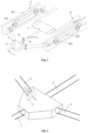
FIG. 1 is a schematic diagram of a stereoscopic structure of an exhaust silencing device; -
FIG. 2 is a schematic structural diagram of a multi-way valve in an exhaust silencing device; -
FIG. 3 is an A-A sectional view shown inFIG. 2 ; -
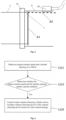
FIG. 4 is a schematic flowchart of an exhaust silencing method; and -
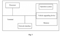
FIG. 5 is a schematic structural diagram of an exhaust silencing terminal. - Reference numerals in the drawings correspondingly are: 1-air intake pipe, 2-main exhaust silencing cylinder, 3-main exhaust pipe, 4-auxiliary exhaust silencing device, 401-housing device, 402-auxiliary exhaust silencing cylinder, 5-auxiliary exhaust pipe, 6-multi-way valve, 7-one-way solenoid valve, 701-solenoid valve time-sharing control sensor, 8-first exhaust pipeline, 9-second exhaust pipeline, and 10-flange.
- To clarify the purpose, technical solutions and advantages of the present application, the present application will be further described in detail below with reference to the accompanying drawings.
- It should be noted that the terms "first", "second", and the like in the specification, the claims, and the drawings of the present application are used to distinguish between similar objects and not necessarily to describe a specific sequence or order. The terms "include" and "have" and any variations thereof are intended to cover a non-exclusive inclusion. In different implementation variations, the same components have the same reference numerals.
-
FIG. 1 shows a schematic diagram of a stereoscopic structure of an exhaust silencing device disclosed in the present application, and the exhaust silencing device includes anair intake pipe 1, a mainexhaust silencing cylinder 2, amain exhaust pipe 3, amulti-way valve 6, at least one auxiliary exhaust silencing device 4, and at least oneauxiliary exhaust pipe 5, where - the
multi-way valve 6 is in communication with theair intake pipe 1, themain exhaust pipe 3, and theauxiliary exhaust pipe 5 respectively; - specifically, an air intake end of the multi-way valve is in communication with the
air intake pipe 1, and an exhaust end thereof is in communication with themain exhaust pipe 3 and theauxiliary exhaust pipe 5 respectively; - one end of the main
exhaust silencing cylinder 2 is in communication with themulti-way valve 6 by means of themain exhaust pipe 3, and the other end of the main exhaust silencing cylinder is in communication with the outside; and - one end of the auxiliary exhaust silencing device 4 is in communication with the
multi-way valve 6 by means of theauxiliary exhaust pipe 5, and the other end of the auxiliary exhaust silencing device is in communication with the outside. - Specifically, the
multi-way valve 6 includes a main exhaust port and at least one auxiliary exhaust port which is provided corresponding to theauxiliary exhaust pipe 5; - the
multi-way valve 6 is in communication with themain exhaust pipe 3 by means of the main exhaust port; and - the
multi-way valve 6 is in communication with theauxiliary exhaust pipe 5 by means of the auxiliary exhaust port. - As shown in
FIG. 1 , two auxiliary exhaust silencing devices 4 are provided, and the number of theauxiliary exhaust pipes 5 is the same as that of the auxiliary exhaust silencing devices 4. - Preferably, two auxiliary exhaust ports may be provided, that is, the
multi-way valve 6 includes one main exhaust port and two auxiliary exhaust ports, and specifically, twoauxiliary exhaust pipes 5 provided correspondingly to the auxiliary exhaust ports are also provided; the two auxiliary exhaust silencing devices 4 are in communication with the auxiliary exhaust ports of the multi-way valve by means of theauxiliary exhaust pipes 5; and at this time, themulti-way valve 6 may be a three-way valve. - Specifically, the exhaust pipe and the
auxiliary exhaust pipe 5 are fixedly connected to themulti-way valve 6 by means offlanges 10. - As shown in
FIG. 2 , at least one one-way solenoid valve 7 is further included, where the one-way solenoid valve 7 is provided corresponding to the auxiliary exhaust port; - the one-
way solenoid valve 7 is provided at the auxiliary exhaust port in themulti-way valve 6; and - the one-
way solenoid valve 7 is configured to control opening and closing of the auxiliary exhaust port. - As shown in
FIG. 2 , at least one one-way solenoid valve 7 is further included, where the one-way solenoid valve 7 is provided corresponding to theauxiliary exhaust pipe 5; - the one-
way solenoid valve 7 is provided in theauxiliary exhaust pipe 5; and - the one-
way solenoid valve 7 is configured to control opening and closing of theauxiliary exhaust pipe 5. - Preferably, when two auxiliary exhaust ports and two
auxiliary exhaust pipes 5 are provided, two corresponding one-way solenoid valves 7 are also provided, and each one-way solenoid valve 7 controls opening or closing of one auxiliary exhaust port or oneauxiliary exhaust pipe 5. - Specifically, as shown in
FIG. 3 , when the one-way solenoid valve 7 is at A1 position, the one-way solenoid valve 7 is in a closed state, and when the one-way solenoid valve 7 is at A2 position, the one-way solenoid valve 7 is in an open state. - As shown in
FIGs. 1 and 2 , the exhaust silencing device further includes a first exhaust pipeline 8 and asecond exhaust pipeline 9, where - one end of the first exhaust pipeline 8 is in communication with the main
exhaust silencing cylinder 2, and the other end of the first exhaust pipeline is in communication with the outside; and - one end of the
second exhaust pipeline 9 is in communication with the auxiliary exhaust silencing device 4, and the other end of the second exhaust pipeline is in communication with the outside. This design may discharge gas in the mainexhaust silencing cylinder 2 or the auxiliary exhaust silencing device 4 into the air. - Preferably, one end of the
second exhaust pipeline 9 is in communication with the auxiliary exhaust silencing device 4, and the other end of the second exhaust pipeline is in communication with the outside by means of the first exhaust pipeline 8, that is, thesecond exhaust pipeline 9 discharges exhaust gases into the air by means of the first exhaust pipeline 8. - As shown in
FIG. 1 , the auxiliary exhaust silencing device 4 includes ahousing device 401 having a closed cavity;
one end of thehousing device 401 is in communication with themulti-way valve 6 by means of theauxiliary exhaust pipe 5, and the other end of the housing device is in communication with the outside. In the present application, that is, thehousing device 401 is directly used as the auxiliary exhaust silencing device 4 to implement a function of exhaust silencing. - Specifically, when the
housing device 401 is used as the auxiliary exhaust silencing device 4, thehousing device 401 is required to have functions of heat resistance and silencing. - As shown in
FIG. 1 , the auxiliary exhaust silencing device 4 further includes an auxiliaryexhaust silencing cylinder 402 fixedly provided in the closed cavity of thehousing device 401. - One end of the auxiliary
exhaust silencing cylinder 402 in thehousing device 401 is in communication with themulti-way valve 6 by means of theauxiliary exhaust pipe 5, and the other end of the auxiliary exhaust silencing cylinder is in communication with the outside. In the present application, thehousing device 401 is provided with the auxiliaryexhaust silencing cylinder 402, which enables thehousing device 401 and the auxiliaryexhaust silencing cylinder 402 to be jointly used as the auxiliary exhaust silencing device 4 to implement the function of exhaust silencing. - Specifically, when the
housing device 401 cannot implement the function of exhaust silencing alone, it is necessary to provide the auxiliaryexhaust silencing cylinder 402 which can implement the function of exhaust silencing in thehousing device 401. - Preferably, a thermal insulating layer and the like may be further provided in the auxiliary
exhaust silencing cylinder 402. - Specifically, the auxiliary
exhaust silencing cylinder 402 is connected to thehousing device 401 by means of a rubber sleeve. - Specifically, one end of the rubber sleeve is fixedly connected to the
housing device 401, the other end of the rubber sleeve is fixedly connected to the auxiliaryexhaust silencing cylinder 402, and in the present application, by using this soft connection manner, a damping effect during vehicle movement may be strengthened, such that abrasion of the auxiliaryexhaust silencing cylinder 402 is reduced, thereby improving a service life of the auxiliaryexhaust silencing cylinder 402. - Preferably, the rubber sleeve may be sleeved on the auxiliary
exhaust silencing cylinder 402, and an outer wall of the auxiliaryexhaust silencing cylinder 402 may further be provided with a buffer layer which has a function of high-temperature resistance. - By providing the auxiliary exhaust silencing device 4, the exhaust silencing device of the present application may reduce the volume of the main
exhaust silencing cylinder 2, has a good noise reduction effect and a simple structure, and is easy to implement. - The present application further provides an exhaust silencing system, including a rotational speed sensor, a throttle sensor, a control device, and the above exhaust silencing device;
- specifically, the rotational speed sensor, the throttle sensor, and the control device are provided on a vehicle body, and the control device may be an ECU control center;
- the control device is communicatively connected to the rotational speed sensor, the throttle sensor, and the one-
way solenoid valve 7 of the exhaust silencing device respectively; - the rotational speed sensor is configured to detect an engine rotation speed of a vehicle;
- the throttle sensor is configured to detect a throttle opening of the vehicle;
- the control device is configured to receive the engine rotation speed sent by the rotational speed sensor and the throttle opening sent by the throttle sensor;
- the control device is configured to analyze and process the engine rotation speed and the throttle opening to obtain an analysis result; and
- the control device is configured to control the one-
way solenoid valve 7 to open or close based on the analysis result. - Specifically, the control device is configured to analyze and process the engine rotation speed and the throttle opening, to determine whether the engine rotation speed and the throttle opening satisfy a preset condition; and
if the analysis result is that the engine rotation speed and the throttle opening satisfy the preset condition, the control device controls one one-way solenoid valve 7 to open. - If the analysis result is that the engine rotation speed and the throttle opening do not satisfy the preset condition, the control device controls the one-
way solenoid valve 7 to close or controls at least one one-way solenoid valve 7 to open. - Specifically, as shown in
FIG. 3 , the one-way solenoid valve 7 includes a solenoid valve time-sharing control sensor 701 which is communicatively connected to the control device; - the control device is configured to generate an instruction for controlling the one-
way solenoid valve 7 to open or close based on the analysis result, and send the instruction to the solenoid valve time-sharing control sensor 701; and - the solenoid valve time-
sharing control sensor 701 is configured to receive the instruction sent by the control device, and execute the instruction, to make the one-way solenoid valve 7 close or open. - The exhaust silencing system of the present application can control the one-
way solenoid valve 7 based on the engine rotation speed and the throttle opening of the vehicle, that is, control opening and closing of the auxiliary exhaust silencing device 4, can implement time-sharing control, and has a simple control principle. - The present application further provides a vehicle, including a vehicle body and the above exhaust silencing system, and one end of the
air intake pipe 1 is in communication with themulti-way valve 6, and the other end of the air intake pipe is in communication with an exhaust cylinder of the vehicle; and
themulti-way valve 6 is provided on a floor of the vehicle body, the mainexhaust silencing cylinder 2 is provided at a bottom of a trunk of the vehicle body, and the auxiliary exhaust silencing device 4 is provided at a bottom of the vehicle body. - Specifically, one end of the
air intake pipe 1 away from themulti-way valve 6 is connected to the exhaust cylinder of the vehicle engine. - Specifically, the
housing device 401 of the auxiliary exhaust silencing device 4 includes a vehicle body rear longitudinal beam, a vehicle body wheel cover plate, or a vehicle body rear enclosing plate. - Preferably, the
housing device 401 is the vehicle body rear longitudinal beam, and the auxiliaryexhaust silencing cylinder 402 is fixedly provided in the vehicle body rear longitudinal beam, to implement a function of exhaust silencing. - By providing the auxiliary exhaust silencing device 4, the vehicle disclosed in the present application reduces the volume of the main
exhaust silencing cylinder 2, and can reduce a rear trunk space occupied by the mainexhaust silencing cylinder 2, thereby improving an utilization rate of the rear trunk space; and a closed cavity structure at the bottom of the vehicle (e.g., a rear longitudinal beam) is directly used as the auxiliary exhaust silencing device 4, or the auxiliaryexhaust silencing cylinder 402 is provided in the closed cavity structure at the bottom of the vehicle to use the closed cavity and the auxiliaryexhaust silencing cylinder 402 as the auxiliary exhaust silencing device 4 jointly, which is not only easy to implement, but also can improve a noise reduction effect of the vehicle on the premise that the volume of the mainexhaust silencing cylinder 2 is reduced. - The present application further provides an exhaust silencing method, which is implemented based on the above exhaust silencing system. As shown in
FIG. 4, FIG. 4 is a schematic flowchart of an exhaust silencing method, specifically as follows:
the method includes: - S101: obtaining an engine rotation speed and an throttle opening of a vehicle; and
- specifically, during a process of vehicle driving, obtaining the engine rotation speed and the throttle opening of the vehicle in real time.
- S103: determining whether the engine rotation speed and the throttle opening satisfy a preset condition; and
- specifically, determining whether the engine rotation speed and the throttle opening satisfy a preset condition includes:
- A1, determining whether the engine rotation speed is not less than a preset first threshold and less than a preset second threshold; and determining whether the throttle opening is not less than a preset third threshold and less than a preset fourth threshold; and
- A2, when the engine rotation speed is not less than the preset first threshold and less than the preset second threshold and/or the throttle opening is not less than the preset third threshold and less than the preset fourth threshold, determining that the engine rotation speed and the throttle opening satisfy the preset condition.
- Specifically, when only the engine rotation speed is not less than the preset first threshold and less than the preset second threshold, it may be determined that the engine rotation speed and the throttle opening satisfying the preset condition;
- when only the throttle opening is not less than the preset third threshold and less than the preset fourth threshold, it may be determined that the engine rotation speed and the throttle opening satisfying the preset condition; and
- when the engine rotation speed is not less than the preset first threshold and less than the preset second threshold and the throttle opening is not less than the preset third threshold and less than the preset fourth threshold, it may also be determined that the engine rotation speed and the throttle opening satisfying the preset condition.
- Specifically, the preset first threshold may be 3,000 r/min, and the preset second threshold may be 4,000 r/min; and the preset third threshold may be the throttle opening achieving 1/3, and the preset fourth threshold may be the throttle opening achieving 1/2.
- S105: if the engine rotation speed and the throttle opening satisfy the preset condition, controlling a main exhaust silencing cylinder and an auxiliary exhaust silencing device of the exhaust silencing device based on a first control strategy.
- Specifically, the first control strategy may be controlling the main exhaust silencing cylinder and one auxiliary exhaust silencing device of the exhaust silencing device to open.
- That is, if the engine rotation speed and the throttle opening satisfy the preset condition, the main exhaust silencing cylinder and one auxiliary exhaust silencing device of the exhaust silencing device are controlled to open; and at this time, the main exhaust silencing cylinder and the one auxiliary exhaust silencing device perform exhaust silencing simultaneously, to implement demands for silencing and exhausting of the engine.
- After determining whether the engine rotation speed and the throttle opening satisfy a preset condition, the method further includes:
when the engine rotation speed and the throttle opening do not satisfy the preset condition, the method further including: - B1, determining whether the engine rotation speed is less than the preset first threshold, and determining whether the throttle opening is less than the preset third threshold; and
- B2, if the engine rotation speed is less than the preset first threshold and the throttle opening is less than the preset third threshold, controlling the main exhaust silencing cylinder and the auxiliary exhaust silencing device of the exhaust silencing device based on a second control strategy.
- Specifically, the second control strategy may be controlling the main exhaust silencing cylinder to open and controlling the auxiliary exhaust silencing device to close.
- That is, if the engine rotation speed is less than the preset first threshold and the throttle opening is less than the preset third threshold, the main exhaust silencing cylinder is controlled to open and the auxiliary exhaust silencing device is controlled to close; and at this time, only the main exhaust silencing cylinder performs the exhaust silencing, and demands for silencing and exhausting of the engine may be implemented.
- When the engine rotation speed and the throttle opening do not satisfy the preset condition, the method further includes:
- C1, determining whether the engine rotation speed is not less than the preset second threshold, and determining whether the throttle opening is not less than the preset fourth threshold; and
- C2, if the engine rotation speed is not less than the preset second threshold, and the throttle opening is not less than the preset fourth threshold, controlling the main exhaust silencing cylinder and the auxiliary exhaust silencing device of the exhaust silencing device based on a third control strategy.
- Specifically, the third control strategy may be controlling the main exhaust silencing cylinder and at least one auxiliary exhaust silencing device to open.
- That is, if the engine rotation speed is not less than the preset second threshold, and the throttle opening is not less than the preset fourth threshold, the main exhaust silencing cylinder and at least one auxiliary exhaust silencing device are controlled to open.
- Preferably, when two auxiliary exhaust silencing devices are provided, the third control strategy may be controlling the main exhaust silencing cylinder and the two auxiliary exhaust silencing devices to open; and at this time, an exhaust silencing effect of the engine can be better improved.
- The exhaust silencing method of the present application controls the main exhaust silencing cylinder and the auxiliary exhaust silencing device by using different control strategies based on changes of the engine rotation speed and the throttle opening, and implements intelligent time-sharing control for the exhaust silencing device.
- The present application further provides an exhaust silencing terminal, the terminal including a processor and a memory, where the memory stores at least one instruction or at least one program, and the at least one instruction or the at least one program is loaded and executed by the processor to implement the parking method described in the above method embodiments.
- The memory may be used for storing software programs and modules, and the processor executes various functional applications and data processing by running the software programs and modules stored in the memory. The memory may mainly include a program storage area and a data storage area, where the program storage area may store an operating system, application programs required by a function, etc.; and the data storage area may store data created on the basis of usage of the device, etc.. In addition, the memory may include a high-speed random access memory, and may further include a non-volatile memory such as at least one disk memory device, a flash memory device or other volatile solid state memories. Accordingly, the memory may further include a memory controller to provide the processor with access to the memory.
-
FIG. 5 is a schematic structural diagram of an exhaust silencing terminal provided by the present application, and interior construction of the exhaust silencing terminal may include, but is not limited to: a processor, a network interface, and a memory, where the processor, the network interface, and the memory in the exhaust silencing terminal may be connected to each other by means of a bus or other manners. InFIG. 5 shown in the embodiments of the specification, bus connection is taken as an example. - The processor (or called as a central processing unit (CPU)) is a computing core and a control core of the exhaust silencing terminal. The network interface may optionally include standard wired interfaces and wireless interfaces (such as WI-FI, and mobile communication interfaces). The memory is a memory device in the exhaust silencing terminal and is configured to store programs and data. It should be understood that the memory herein may be a high speed RAM storage device, may be a non-volatile memory device, such as at least one disk storage device, or may optionally further be at least one storage device away from the foregoing processor. The memory provides a storage space which stores an operation system of the exhaust silencing terminal and the operation system may include but is not limited to: a Windows system (an operation system), a Linux (an operation system), and the like which are not limited by the present invention; and the storage space further stores one or more instructions which are applicable to be loaded and executed by the processor, and these instructions may be one or more computer programs (including program codes). In the embodiments of the specification, the processor loads and executes the one or more instructions stored in the memory, to implement the exhaust silencing method provided by the above method embodiments.
- That is, if the engine rotation speed and the throttle opening satisfy the preset condition, the main exhaust silencing cylinder and one auxiliary exhaust silencing device of the exhaust silencing device are controlled to open; and at this time, the main exhaust silencing cylinder and the one auxiliary exhaust silencing device perform exhaust silencing simultaneously, to implement demands for silencing and exhausting of the engine.
- After determining whether the engine rotation speed and the throttle opening satisfy a preset condition, the method further includes:
when the engine rotation speed and the throttle opening do not satisfy the preset condition, the method further including: -
B 1, determining whether the engine rotation speed is less than the preset first threshold, and determining whether the throttle opening is less than the preset third threshold; and - B2, if the engine rotation speed is less than the preset first threshold and the throttle opening is less than the preset third threshold, controlling the main exhaust silencing cylinder and the auxiliary exhaust silencing device of the exhaust silencing device based on a second control strategy.
- Specifically, the second control strategy may be controlling the main exhaust silencing cylinder to open and controlling the auxiliary exhaust silencing device to close.
- That is, if the engine rotation speed is less than the preset first threshold and the throttle opening is less than the preset third threshold, the main exhaust silencing cylinder is controlled to open and the auxiliary exhaust silencing device is controlled to close; and at this time, only the main exhaust silencing cylinder performs the exhaust silencing, and demands for silencing and exhausting of the engine may be implemented.
- When the engine rotation speed and the throttle opening do not satisfy the preset condition, the method further includes:
- C1, determining whether the engine rotation speed is not less than the preset second threshold, and determining whether the throttle opening is not less than the preset fourth threshold; and
- C2, if the engine rotation speed is not less than the preset second threshold, and the throttle opening is not less than the preset fourth threshold, controlling the main exhaust silencing cylinder and the auxiliary exhaust silencing device of the exhaust silencing device based on a third control strategy.
- Specifically, the third control strategy may be controlling the main exhaust silencing cylinder and at least one auxiliary exhaust silencing device to open.
- That is, if the engine rotation speed is not less than the preset second threshold, and the throttle opening is not less than the preset fourth threshold, the main exhaust silencing cylinder and at least one auxiliary exhaust silencing device are controlled to open.
- Preferably, when two auxiliary exhaust silencing devices are provided, the third control strategy may be controlling the main exhaust silencing cylinder and the two auxiliary exhaust silencing devices to open; and at this time, an exhaust silencing effect of the engine can be better improved.
- The exhaust silencing method of the present application controls the main exhaust silencing cylinder and the auxiliary exhaust silencing device by using different control strategies based on changes of the engine rotation speed and the throttle opening, and implements intelligent time-sharing control for the exhaust silencing device.
- The present application further provides an exhaust silencing terminal, the terminal including a processor and a memory, where the memory stores at least one instruction or at least one program, and the at least one instruction or the at least one program is loaded and executed by the processor to implement the parking method described in the above method embodiments.
- The memory may be used for storing software programs and modules, and the processor executes various functional applications and data processing by running the software programs and modules stored in the memory. The memory may mainly include a program storage area and a data storage area, where the program storage area may store an operating system, application programs required by a function, etc.; and the data storage area may store data created on the basis of usage of the device, etc.. In addition, the memory may include a high-speed random access memory, and may further include a non-volatile memory such as at least one disk memory device, a flash memory device or other volatile solid state memories. Accordingly, the memory may further include a memory controller to provide the processor with access to the memory.
-
FIG. 5 is a schematic structural diagram of an exhaust silencing terminal provided by the present application, and interior construction of the exhaust silencing terminal may include, but is not limited to: a processor, a network interface, and a memory, where the processor, the network interface, and the memory in the exhaust silencing terminal may be connected to each other by means of a bus or other manners. InFIG. 5 shown in the embodiments of the specification, bus connection is taken as an example. - The processor (or called as a central processing unit (CPU)) is a computing core and a control core of the exhaust silencing terminal. The network interface may optionally include standard wired interfaces and wireless interfaces (such as WI-FI, and mobile communication interfaces). The memory is a memory device in the exhaust silencing terminal and is configured to store programs and data. It should be understood that the memory herein may be a high speed RAM storage device, may be a non-volatile memory device, such as at least one disk storage device, or may optionally further be at least one storage device away from the foregoing processor. The memory provides a storage space which stores an operation system of the exhaust silencing terminal and the operation system may include but is not limited to: a Windows system (an operation system), a Linux (an operation system), and the like which are not limited by the present invention; and the storage space further stores one or more instructions which are applicable to be loaded and executed by the processor, and these instructions may be one or more computer programs (including program codes). In the embodiments of the specification, the processor loads and executes the one or more instructions stored in the memory, to implement the exhaust silencing method provided by the above method embodiments.
- The above disclosure is only a preferred embodiment of the present application, and certainly, the scope of rights of the present application cannot be limited based on this. Therefore, equivalent variations made based on the claims of the present application still fall within the scope encompassed by the present application.
Claims (11)
- A vehicle, comprising:a vehicle body; andan exhaust silencing system, comprising:a rotational speed sensor,a throttle sensor,a control device, andan exhaust silencing device, comprising:an air intake pipe (1), a main exhaust silencing cylinder (2), a main exhaust pipe (3), a multi-way valve (6), at least one auxiliary exhaust silencing device (4), and at least one auxiliary exhaust pipe (5), whereinthe multi-way valve (6) is in communication with the air intake pipe (1), the main exhaust pipe (3), and the auxiliary exhaust pipe (5) respectively;one end of the main exhaust silencing cylinder (2) is in communication with the multi-way valve (6) by means of the main exhaust pipe (3), and the other end of the main exhaust silencing cylinder is in communication with the outside; andone end of the auxiliary exhaust silencing device (4) is in communication with the multi-way valve (6) by means of the auxiliary exhaust pipe (5), and the other end the auxiliary exhaust silencing device is in communication with the outside;wherein the control device is communicatively connected to the rotational speed sensor, the throttle sensor, and a one-way solenoid valve (7) of the exhaust silencing device respectively;the rotational speed sensor is configured to detect an engine rotation speed of the vehicle;the throttle sensor is configured to detect a throttle opening of the vehicle;the control device is configured to receive the engine rotation speed sent by the rotational speed sensor and the throttle opening sent by the throttle sensor, analyze and process the engine rotation speed and the throttle opening to obtain an analysis result, and control the one-way solenoid valve (7) to open or close based on the analysis result;one end of the air intake pipe (1) is in communication with the multi-way valve (6), and the other end of the air intake pipe is in communication with an exhaust cylinder of the vehicle;characterized in thatthe auxiliary exhaust silencing device (4) comprises a housing device (401) having a closed cavity, and an auxiliary exhaust silencing cylinder (402) fixedly provided in the closed cavity of the housing device (401), wherein one end of the auxiliary exhaust silencing cylinder (402) in the housing device (401) is in communication with the multi-way valve (6) by means of the auxiliary exhaust pipe (5), and the other end of the auxiliary exhaust silencing cylinder is in communication with the outside;the multi-way valve (6) is provided on a floor of the vehicle body, the main exhaust silencing cylinder (2) is provided at a bottom of a trunk of the vehicle body, and the auxiliary exhaust silencing device (4) is provided at a bottom of the vehicle body, wherein the housing device (401) of the auxiliary exhaust silencing device (4) comprises a vehicle body rear longitudinal beam, a vehicle body wheel cover plate, or a vehicle body rear enclosing plate.
- The vehicle according to claim 1, characterized in that the multi-way valve (6) comprises a main exhaust port and at least one auxiliary exhaust port which is provided corresponding to the auxiliary exhaust pipe (5);the multi-way valve (6) is in communication with the main exhaust pipe (3) by means of the main exhaust port; andthe multi-way valve (6) is in communication with the auxiliary exhaust pipe (5) by means of the auxiliary exhaust port.
- The vehicle according to claim 2, characterized in that at least one one-way solenoid valve (7) is provided corresponding to the auxiliary exhaust port;the one-way solenoid valve (7) is provided at the auxiliary exhaust port in the multi-way valve (6); andthe one-way solenoid valve (7) is configured to control opening and closing of the auxiliary exhaust port; orat least one one-way solenoid valve (7) is provided corresponding to the auxiliary exhaust pipe (5);the one-way solenoid valve (7) is provided in the auxiliary exhaust pipe (5); andthe one-way solenoid valve (7) is configured to control opening and closing of the auxiliary exhaust pipe (5).
- The vehicle according to any one of claims 1 to 3, characterized in that the exhaust silencing device further comprises a first exhaust pipeline (8) and a second exhaust pipeline (9), whereinone end of the first exhaust pipeline (8) is in communication with the main exhaust silencing cylinder (2), and the other end of the first exhaust pipeline is in communication with the outside; andone end of the second exhaust pipeline (9) is in communication with the auxiliary exhaust silencing device (4), and the other end of the second exhaust pipeline is in communication with the outside, characterized in thatone end of the second exhaust pipeline (9) is in communication with the auxiliary exhaust silencing device (4), and the other end of the second exhaust pipeline is in communication with the outside by means of the first exhaust pipeline (8).
- The vehicle according to claim 2 or 3, characterized in that two auxiliary exhaust silencing devices (4) are provided, and the number of the auxiliary exhaust pipes (5) is the same as that of the auxiliary exhaust silencing devices (4); and
the multi-way valve (6) comprises two auxiliary exhaust ports, and the two auxiliary exhaust silencing devices (4) are in communication with the auxiliary exhaust ports of the multi-way valve by means of the auxiliary exhaust pipes (5). - The vehicle according to any one of claims 1 to 5, characterized in that the exhaust pipe and the auxiliary exhaust pipe (5) are fixedly connected to the multi-way valve (6) by means of flanges (10).
- The vehicle according to claims 1 to 6, characterized in that the one-way solenoid valve (7) comprises a solenoid valve time-sharing control sensor (701) communicatively connected to the control device;the control device is configured to generate an instruction for controlling the one-way solenoid valve (7) to open or close based on the analysis result, and send the instruction to the solenoid valve time-sharing control sensor (701); andthe solenoid valve time-sharing control sensor (701) is configured to receive the instruction sent by the control device, and execute the instruction.
- An exhaust silencing method for the vehicle according to claims 1 to 7, the method comprising:obtaining an engine rotation speed and a throttle opening of a vehicle;determining whether the engine rotation speed and the throttle opening satisfy a preset condition; andif the engine rotation speed and the throttle opening satisfy the preset condition, controlling the main exhaust silencing cylinder and the auxiliary exhaust silencing device of the exhaust silencing device based on a first control strategy.
- The exhaust silencing method according to claim 8, characterized in that determining whether the engine rotation speed and the throttle opening satisfy a preset condition comprises:determining whether the engine rotation speed is not less than a preset first threshold and less than a preset second threshold; determining whether the throttle opening is not less than a preset third threshold and less than a preset fourth threshold; andwhen the engine rotation speed is not less than the preset first threshold and less than the preset second threshold and/or the throttle opening is not less than the preset third threshold and less than the preset fourth threshold, determining that the engine rotation speed and the throttle opening satisfy the preset condition.
- The exhaust silencing method according to claim 9, characterized in that
when the engine rotation speed and the throttle opening do not satisfy the preset condition, the method further comprises:determining whether the engine rotation speed is less than the preset first threshold, and determining whether the throttle opening is less than the preset third threshold; andif the engine rotation speed is less than the preset first threshold and the throttle opening is less than the preset third threshold, controlling the main exhaust silencing cylinder and the auxiliary exhaust silencing device of the exhaust silencing device based on a second control strategy, characterized in that:the first control strategy comprises controlling the main exhaust silencing cylinder and one auxiliary exhaust silencing device of the exhaust silencing device to open; andthe second control strategy comprises controlling the main exhaust silencing cylinder to open and controlling the auxiliary exhaust silencing device to close. - The exhaust silencing method according to claim 9, characterized in that when the engine rotation speed and the throttle opening do not satisfy the preset condition, the method further comprises:determining whether the engine rotation speed is not less than the preset second threshold, and determining whether the throttle opening is not less than the preset fourth threshold; andif the engine rotation speed is not less than the preset second threshold, and the throttle opening is not less than the preset fourth threshold, controlling the main exhaust silencing cylinder and the auxiliary exhaust silencing device of the exhaust silencing device based on a third control strategy, characterized in thatthe third control strategy comprises controlling the main exhaust silencing cylinder and at least one auxiliary exhaust silencing device to open, characterized in thattwo auxiliary exhaust silencing devices are provided, and the method further comprises:
the third control strategy being controlling the main exhaust silencing cylinder and the two auxiliary exhaust silencing devices to open.
Applications Claiming Priority (1)
| Application Number | Priority Date | Filing Date | Title |
|---|---|---|---|
| PCT/CN2020/101769 WO2022011525A1 (en) | 2020-07-14 | 2020-07-14 | Exhaust silencing device and system, vehicle, and exhaust silencing method |
Publications (4)
| Publication Number | Publication Date |
|---|---|
| EP4155516A1 EP4155516A1 (en) | 2023-03-29 |
| EP4155516A4 EP4155516A4 (en) | 2023-07-12 |
| EP4155516B1 true EP4155516B1 (en) | 2024-03-13 |
| EP4155516C0 EP4155516C0 (en) | 2024-03-13 |
Family
ID=79554400
Family Applications (1)
| Application Number | Title | Priority Date | Filing Date |
|---|---|---|---|
| EP20945691.2A Active EP4155516B1 (en) | 2020-07-14 | 2020-07-14 | Vehicle with an exhaust silencing system and method for exhaust silencing of a vehicle |
Country Status (5)
| Country | Link |
|---|---|
| US (1) | US12404790B2 (en) |
| EP (1) | EP4155516B1 (en) |
| KR (1) | KR102768237B1 (en) |
| CN (1) | CN115943251B (en) |
| WO (1) | WO2022011525A1 (en) |
Families Citing this family (1)
| Publication number | Priority date | Publication date | Assignee | Title |
|---|---|---|---|---|
| US12404790B2 (en) * | 2020-07-14 | 2025-09-02 | Zhejiang Geely Holding Group Co., Ltd | Exhaust silencing device and system, vehicle, and exhaust silencing method |
Family Cites Families (38)
| Publication number | Priority date | Publication date | Assignee | Title |
|---|---|---|---|---|
| US5388408A (en) * | 1993-10-01 | 1995-02-14 | Lawrence-Keech Inc. | Exhaust system for internal combustion engines |
| DE10020491A1 (en) * | 2000-04-26 | 2002-03-14 | Eberspaecher J Gmbh & Co | Muffler system of a motor vehicle with variable damping characteristics |
| JP2002155741A (en) * | 2000-09-11 | 2002-05-31 | Calsonic Kansei Corp | Control muffler |
| DE10150170A1 (en) * | 2001-03-16 | 2002-09-26 | Bosch Gmbh Robert | Automotive exhaust pipe has infinitely variable flap valve varying gas feed to two branch pipes with regeneration medium variable inlet |
| JP4382316B2 (en) * | 2001-12-04 | 2009-12-09 | 株式会社Esr | Exhaust gas purifying device having frame reinforcing member |
| DE10231056A1 (en) * | 2002-07-10 | 2004-02-05 | J. Eberspächer GmbH & Co. KG | exhaust system |
| CA2477052C (en) * | 2003-08-21 | 2009-10-06 | Honda Motor Co., Ltd. | Self-propelled walk-behind snowplow vehicle |
| US7090048B2 (en) * | 2003-09-26 | 2006-08-15 | General Motors Corporation | Method and apparatus for exhaust sound attenuation on engines with cylinder deactivation |
| JP4270170B2 (en) * | 2004-11-02 | 2009-05-27 | トヨタ自動車株式会社 | Exhaust gas purification device for internal combustion engine |
| JP2007218174A (en) * | 2006-02-16 | 2007-08-30 | Toyota Motor Corp | Variable exhaust system |
| FR2902828B1 (en) * | 2006-06-27 | 2008-09-26 | Renault Sas | EXHAUST LINE OF A DIESEL ENGINE AND METHOD OF DESULFATATION |
| DE102007026812A1 (en) * | 2007-06-06 | 2008-12-11 | J. Eberspächer GmbH & Co. KG | exhaust system |
| DE102007039588B4 (en) * | 2007-08-22 | 2010-01-21 | Audi Ag | Apparatus and method for purifying exhaust gases for an internal combustion engine |
| US8037672B2 (en) * | 2007-10-09 | 2011-10-18 | Delphi Technologies, Inc. | Method and apparatus for detecting a non-operational status of a catalyst in an engine exhaust conduit |
| JP4960936B2 (en) * | 2008-09-08 | 2012-06-27 | 本田技研工業株式会社 | Engine exhaust system |
| GB2462743B (en) * | 2009-07-25 | 2010-07-28 | William Gallacher | Carbon control |
| JP5771113B2 (en) * | 2011-10-06 | 2015-08-26 | 川崎重工業株式会社 | Exhaust silencer |
| DE102011090160B4 (en) * | 2011-12-30 | 2023-02-23 | Dr.Ing.H.C. F. Porsche Ag | Internal combustion engine with an arrangement for routing exhaust gas and charge air |
| US9206726B2 (en) * | 2012-12-12 | 2015-12-08 | Continental Automotive Systems, Inc. | Exhaust mode selector system |
| DE102012112433A1 (en) * | 2012-12-17 | 2014-06-18 | Dr. Ing. H.C. F. Porsche Aktiengesellschaft | Exhaust system for an internal combustion engine |
| KR101511541B1 (en) * | 2013-11-15 | 2015-04-13 | 현대자동차주식회사 | Structure of dual exhaust system for cda engine |
| CN204163817U (en) * | 2014-10-10 | 2015-02-18 | 江阴市曾氏动力机械科技有限公司 | A kind of parallel baffler |
| US9765666B2 (en) * | 2015-02-11 | 2017-09-19 | Fca Us Llc | Dual path aftertreatment system and method utilizing fuel as an on-board reductant for NOx SCR |
| HUE041635T2 (en) * | 2015-07-16 | 2019-05-28 | Akrapovic D D | An exhaust system for an internal combustion automotive engine |
| CN204941679U (en) * | 2015-08-03 | 2016-01-06 | 天津市神驰汽车零部件有限公司 | A kind of automobile exhaust pipe |
| RS58305B1 (en) | 2015-09-10 | 2019-03-29 | Akrapovic D D | Exhaust system for an internal combustion automotive engine |
| CN204921116U (en) * | 2015-09-17 | 2015-12-30 | 顾东海 | Car double -purpose noise eliminator |
| KR101762280B1 (en) * | 2016-03-28 | 2017-07-28 | 현대자동차주식회사 | Structure of central-through type active control valve |
| US20170298802A1 (en) * | 2016-04-14 | 2017-10-19 | Hyundai Motor Company | Structure of exhaust pipe |
| ITUA20164078A1 (en) * | 2016-06-03 | 2017-12-03 | Ferrari Spa | ROAD VEHICLE WITH AN INTERNAL COMBUSTION ENGINE AND PROVIDED WITH A DISCHARGE NOISE TRANSMISSION DEVICE |
| US10584626B2 (en) * | 2018-05-07 | 2020-03-10 | Tenneco Automotive Operating Company Inc. | Muffler assembly including a center muffler and two satellite mufflers |
| US10358956B1 (en) * | 2018-07-09 | 2019-07-23 | Faurecia Emissions Control Technologies, Usa, Llc | Exhaust valve and active noise control for compact exhaust system |
| IT202000007627A1 (en) * | 2020-04-09 | 2021-10-09 | Ferrari Spa | EXHAUST SYSTEM FOR AN INTERNAL COMBUSTION ENGINE |
| US12404790B2 (en) * | 2020-07-14 | 2025-09-02 | Zhejiang Geely Holding Group Co., Ltd | Exhaust silencing device and system, vehicle, and exhaust silencing method |
| US11959406B2 (en) * | 2020-12-30 | 2024-04-16 | Ferrari S.P.A. | Car provided with an exhaust system with aerodynamic effect |
| US11988124B2 (en) * | 2020-12-30 | 2024-05-21 | Ferrari S.P.A. | Exhaust system for an internal combustion engine |
| GB202312768D0 (en) * | 2023-08-21 | 2023-10-04 | Mclaren Automotive Ltd | Improving acoustic efficiency |
| US12448907B2 (en) * | 2023-08-24 | 2025-10-21 | Tenneco Automotive Operating Company Llc | Dual mode muffler |
-
2020
- 2020-07-14 US US18/016,000 patent/US12404790B2/en active Active
- 2020-07-14 WO PCT/CN2020/101769 patent/WO2022011525A1/en not_active Ceased
- 2020-07-14 KR KR1020237002276A patent/KR102768237B1/en active Active
- 2020-07-14 CN CN202080102250.XA patent/CN115943251B/en active Active
- 2020-07-14 EP EP20945691.2A patent/EP4155516B1/en active Active
Also Published As
| Publication number | Publication date |
|---|---|
| KR20230031300A (en) | 2023-03-07 |
| US20230212968A1 (en) | 2023-07-06 |
| CN115943251A (en) | 2023-04-07 |
| EP4155516A1 (en) | 2023-03-29 |
| WO2022011525A1 (en) | 2022-01-20 |
| US12404790B2 (en) | 2025-09-02 |
| EP4155516A4 (en) | 2023-07-12 |
| CN115943251B (en) | 2025-11-28 |
| EP4155516C0 (en) | 2024-03-13 |
| KR102768237B1 (en) | 2025-02-18 |
Similar Documents
| Publication | Publication Date | Title |
|---|---|---|
| US9109483B2 (en) | Exhaust system for an internal combustion engine | |
| CN101115919B (en) | Exhaust throttle exhaust gas recirculation valve module for diesel engines | |
| US11187145B2 (en) | Branch communication valve for a twin scroll turbocharger | |
| US8590504B2 (en) | Method for controlling an intake system | |
| CN105804861B (en) | Exhaust control valve branch communication and wastegate | |
| WO2014132544A1 (en) | Control device for internal combustion engine | |
| JP2018193952A (en) | Exhaust emission control device of internal combustion engine | |
| CN107237675B (en) | Muffler apparatus including a centrally shared active control valve | |
| PH12018050030A1 (en) | Exhaust passage structure for internal combustion engine | |
| CN111788378A (en) | Internal combustion engine and control method thereof | |
| CN115943251B (en) | Exhaust silencing device, system, vehicle and exhaust silencing method | |
| WO2015166658A1 (en) | Air bypass valve control device | |
| JP4960936B2 (en) | Engine exhaust system | |
| JP6414412B2 (en) | Exhaust system for internal combustion engine | |
| JP2000080916A (en) | Exhaust system for multi-cylinder internal combustion engine | |
| US11319848B2 (en) | Variable valve for muffler and dual muffler having the same | |
| US20220325660A1 (en) | Turbocharger system with turbine bypass circuit to reduce emissions during engine cold start | |
| JP4199067B2 (en) | Exhaust device for vehicle engine | |
| US6295960B1 (en) | Intake manifold communication valve | |
| JP2008190413A (en) | Engine intake system | |
| JP2871737B2 (en) | Engine air intake silencer | |
| JP2002256873A (en) | Variable intake system for internal combustion engine | |
| JP2014181629A (en) | Exhaust gas recirculation device of engine for vehicle | |
| JP2008190414A (en) | Engine intake system | |
| JP2005194980A (en) | Exhaust cooling system for internal combustion engine |
Legal Events
| Date | Code | Title | Description |
|---|---|---|---|
| STAA | Information on the status of an ep patent application or granted ep patent |
Free format text: STATUS: THE INTERNATIONAL PUBLICATION HAS BEEN MADE |
|
| PUAI | Public reference made under article 153(3) epc to a published international application that has entered the european phase |
Free format text: ORIGINAL CODE: 0009012 |
|
| STAA | Information on the status of an ep patent application or granted ep patent |
Free format text: STATUS: REQUEST FOR EXAMINATION WAS MADE |
|
| 17P | Request for examination filed |
Effective date: 20221223 |
|
| AK | Designated contracting states |
Kind code of ref document: A1 Designated state(s): AL AT BE BG CH CY CZ DE DK EE ES FI FR GB GR HR HU IE IS IT LI LT LU LV MC MK MT NL NO PL PT RO RS SE SI SK SM TR |
|
| REG | Reference to a national code |
Ref country code: DE Ref legal event code: R079 Free format text: PREVIOUS MAIN CLASS: F01N0013040000 Ipc: F01N0001000000 Ref document number: 602020027372 Country of ref document: DE |
|
| STAA | Information on the status of an ep patent application or granted ep patent |
Free format text: STATUS: EXAMINATION IS IN PROGRESS |
|
| A4 | Supplementary search report drawn up and despatched |
Effective date: 20230609 |
|
| RIC1 | Information provided on ipc code assigned before grant |
Ipc: F01N 13/10 20100101ALI20230602BHEP Ipc: F01N 13/08 20100101ALI20230602BHEP Ipc: F01N 13/04 20100101ALI20230602BHEP Ipc: F01N 1/16 20060101ALI20230602BHEP Ipc: F01N 1/00 20060101AFI20230602BHEP |
|
| 17Q | First examination report despatched |
Effective date: 20230621 |
|
| DAV | Request for validation of the european patent (deleted) | ||
| DAX | Request for extension of the european patent (deleted) | ||
| GRAP | Despatch of communication of intention to grant a patent |
Free format text: ORIGINAL CODE: EPIDOSNIGR1 |
|
| STAA | Information on the status of an ep patent application or granted ep patent |
Free format text: STATUS: GRANT OF PATENT IS INTENDED |
|
| RIC1 | Information provided on ipc code assigned before grant |
Ipc: F01N 13/10 20100101ALI20231004BHEP Ipc: F01N 13/08 20100101ALI20231004BHEP Ipc: F01N 13/04 20100101ALI20231004BHEP Ipc: F01N 1/16 20060101ALI20231004BHEP Ipc: F01N 1/00 20060101AFI20231004BHEP |
|
| INTG | Intention to grant announced |
Effective date: 20231103 |
|
| GRAS | Grant fee paid |
Free format text: ORIGINAL CODE: EPIDOSNIGR3 |
|
| GRAA | (expected) grant |
Free format text: ORIGINAL CODE: 0009210 |
|
| STAA | Information on the status of an ep patent application or granted ep patent |
Free format text: STATUS: THE PATENT HAS BEEN GRANTED |
|
| AK | Designated contracting states |
Kind code of ref document: B1 Designated state(s): AL AT BE BG CH CY CZ DE DK EE ES FI FR GB GR HR HU IE IS IT LI LT LU LV MC MK MT NL NO PL PT RO RS SE SI SK SM TR |
|
| REG | Reference to a national code |
Ref country code: GB Ref legal event code: FG4D |
|
| REG | Reference to a national code |
Ref country code: CH Ref legal event code: EP |
|
| REG | Reference to a national code |
Ref country code: DE Ref legal event code: R096 Ref document number: 602020027372 Country of ref document: DE |
|
| REG | Reference to a national code |
Ref country code: IE Ref legal event code: FG4D |
|
| U01 | Request for unitary effect filed |
Effective date: 20240315 |
|
| U07 | Unitary effect registered |
Designated state(s): AT BE BG DE DK EE FI FR IT LT LU LV MT NL PT SE SI Effective date: 20240325 |
|
| PG25 | Lapsed in a contracting state [announced via postgrant information from national office to epo] |
Ref country code: GR Free format text: LAPSE BECAUSE OF FAILURE TO SUBMIT A TRANSLATION OF THE DESCRIPTION OR TO PAY THE FEE WITHIN THE PRESCRIBED TIME-LIMIT Effective date: 20240614 |
|
| PG25 | Lapsed in a contracting state [announced via postgrant information from national office to epo] |
Ref country code: HR Free format text: LAPSE BECAUSE OF FAILURE TO SUBMIT A TRANSLATION OF THE DESCRIPTION OR TO PAY THE FEE WITHIN THE PRESCRIBED TIME-LIMIT Effective date: 20240313 Ref country code: RS Free format text: LAPSE BECAUSE OF FAILURE TO SUBMIT A TRANSLATION OF THE DESCRIPTION OR TO PAY THE FEE WITHIN THE PRESCRIBED TIME-LIMIT Effective date: 20240613 |
|
| PG25 | Lapsed in a contracting state [announced via postgrant information from national office to epo] |
Ref country code: ES Free format text: LAPSE BECAUSE OF FAILURE TO SUBMIT A TRANSLATION OF THE DESCRIPTION OR TO PAY THE FEE WITHIN THE PRESCRIBED TIME-LIMIT Effective date: 20240313 |
|
| PG25 | Lapsed in a contracting state [announced via postgrant information from national office to epo] |
Ref country code: RS Free format text: LAPSE BECAUSE OF FAILURE TO SUBMIT A TRANSLATION OF THE DESCRIPTION OR TO PAY THE FEE WITHIN THE PRESCRIBED TIME-LIMIT Effective date: 20240613 Ref country code: NO Free format text: LAPSE BECAUSE OF FAILURE TO SUBMIT A TRANSLATION OF THE DESCRIPTION OR TO PAY THE FEE WITHIN THE PRESCRIBED TIME-LIMIT Effective date: 20240613 Ref country code: HR Free format text: LAPSE BECAUSE OF FAILURE TO SUBMIT A TRANSLATION OF THE DESCRIPTION OR TO PAY THE FEE WITHIN THE PRESCRIBED TIME-LIMIT Effective date: 20240313 Ref country code: GR Free format text: LAPSE BECAUSE OF FAILURE TO SUBMIT A TRANSLATION OF THE DESCRIPTION OR TO PAY THE FEE WITHIN THE PRESCRIBED TIME-LIMIT Effective date: 20240614 Ref country code: ES Free format text: LAPSE BECAUSE OF FAILURE TO SUBMIT A TRANSLATION OF THE DESCRIPTION OR TO PAY THE FEE WITHIN THE PRESCRIBED TIME-LIMIT Effective date: 20240313 |
|
| U20 | Renewal fee for the european patent with unitary effect paid |
Year of fee payment: 5 Effective date: 20240701 |
|
| PG25 | Lapsed in a contracting state [announced via postgrant information from national office to epo] |
Ref country code: IS Free format text: LAPSE BECAUSE OF FAILURE TO SUBMIT A TRANSLATION OF THE DESCRIPTION OR TO PAY THE FEE WITHIN THE PRESCRIBED TIME-LIMIT Effective date: 20240713 |
|
| PG25 | Lapsed in a contracting state [announced via postgrant information from national office to epo] |
Ref country code: SM Free format text: LAPSE BECAUSE OF FAILURE TO SUBMIT A TRANSLATION OF THE DESCRIPTION OR TO PAY THE FEE WITHIN THE PRESCRIBED TIME-LIMIT Effective date: 20240313 |
|
| PG25 | Lapsed in a contracting state [announced via postgrant information from national office to epo] |
Ref country code: CZ Free format text: LAPSE BECAUSE OF FAILURE TO SUBMIT A TRANSLATION OF THE DESCRIPTION OR TO PAY THE FEE WITHIN THE PRESCRIBED TIME-LIMIT Effective date: 20240313 |
|
| PG25 | Lapsed in a contracting state [announced via postgrant information from national office to epo] |
Ref country code: PL Free format text: LAPSE BECAUSE OF FAILURE TO SUBMIT A TRANSLATION OF THE DESCRIPTION OR TO PAY THE FEE WITHIN THE PRESCRIBED TIME-LIMIT Effective date: 20240313 |
|
| PG25 | Lapsed in a contracting state [announced via postgrant information from national office to epo] |
Ref country code: SK Free format text: LAPSE BECAUSE OF FAILURE TO SUBMIT A TRANSLATION OF THE DESCRIPTION OR TO PAY THE FEE WITHIN THE PRESCRIBED TIME-LIMIT Effective date: 20240313 |
|
| PG25 | Lapsed in a contracting state [announced via postgrant information from national office to epo] |
Ref country code: SM Free format text: LAPSE BECAUSE OF FAILURE TO SUBMIT A TRANSLATION OF THE DESCRIPTION OR TO PAY THE FEE WITHIN THE PRESCRIBED TIME-LIMIT Effective date: 20240313 Ref country code: SK Free format text: LAPSE BECAUSE OF FAILURE TO SUBMIT A TRANSLATION OF THE DESCRIPTION OR TO PAY THE FEE WITHIN THE PRESCRIBED TIME-LIMIT Effective date: 20240313 Ref country code: RO Free format text: LAPSE BECAUSE OF FAILURE TO SUBMIT A TRANSLATION OF THE DESCRIPTION OR TO PAY THE FEE WITHIN THE PRESCRIBED TIME-LIMIT Effective date: 20240313 Ref country code: PL Free format text: LAPSE BECAUSE OF FAILURE TO SUBMIT A TRANSLATION OF THE DESCRIPTION OR TO PAY THE FEE WITHIN THE PRESCRIBED TIME-LIMIT Effective date: 20240313 Ref country code: IS Free format text: LAPSE BECAUSE OF FAILURE TO SUBMIT A TRANSLATION OF THE DESCRIPTION OR TO PAY THE FEE WITHIN THE PRESCRIBED TIME-LIMIT Effective date: 20240713 Ref country code: CZ Free format text: LAPSE BECAUSE OF FAILURE TO SUBMIT A TRANSLATION OF THE DESCRIPTION OR TO PAY THE FEE WITHIN THE PRESCRIBED TIME-LIMIT Effective date: 20240313 |
|
| REG | Reference to a national code |
Ref country code: DE Ref legal event code: R097 Ref document number: 602020027372 Country of ref document: DE |
|
| PLBE | No opposition filed within time limit |
Free format text: ORIGINAL CODE: 0009261 |
|
| STAA | Information on the status of an ep patent application or granted ep patent |
Free format text: STATUS: NO OPPOSITION FILED WITHIN TIME LIMIT |
|
| PG25 | Lapsed in a contracting state [announced via postgrant information from national office to epo] |
Ref country code: MC Free format text: LAPSE BECAUSE OF FAILURE TO SUBMIT A TRANSLATION OF THE DESCRIPTION OR TO PAY THE FEE WITHIN THE PRESCRIBED TIME-LIMIT Effective date: 20240313 |
|
| 26N | No opposition filed |
Effective date: 20241216 |
|
| REG | Reference to a national code |
Ref country code: CH Ref legal event code: PL |
|
| PG25 | Lapsed in a contracting state [announced via postgrant information from national office to epo] |
Ref country code: CH Free format text: LAPSE BECAUSE OF NON-PAYMENT OF DUE FEES Effective date: 20240731 |
|
| U20 | Renewal fee for the european patent with unitary effect paid |
Year of fee payment: 6 Effective date: 20250527 |
|
| PGFP | Annual fee paid to national office [announced via postgrant information from national office to epo] |
Ref country code: GB Payment date: 20250527 Year of fee payment: 6 |
|
| PG25 | Lapsed in a contracting state [announced via postgrant information from national office to epo] |
Ref country code: IE Free format text: LAPSE BECAUSE OF NON-PAYMENT OF DUE FEES Effective date: 20240714 |
|
| PG25 | Lapsed in a contracting state [announced via postgrant information from national office to epo] |
Ref country code: CY Free format text: LAPSE BECAUSE OF FAILURE TO SUBMIT A TRANSLATION OF THE DESCRIPTION OR TO PAY THE FEE WITHIN THE PRESCRIBED TIME-LIMIT; INVALID AB INITIO Effective date: 20200714 |
|
| PG25 | Lapsed in a contracting state [announced via postgrant information from national office to epo] |
Ref country code: HU Free format text: LAPSE BECAUSE OF FAILURE TO SUBMIT A TRANSLATION OF THE DESCRIPTION OR TO PAY THE FEE WITHIN THE PRESCRIBED TIME-LIMIT; INVALID AB INITIO Effective date: 20200714 |