EP4155490A1 - Inner handle for automobile and application thereof - Google Patents
Inner handle for automobile and application thereof Download PDFInfo
- Publication number
- EP4155490A1 EP4155490A1 EP22187331.8A EP22187331A EP4155490A1 EP 4155490 A1 EP4155490 A1 EP 4155490A1 EP 22187331 A EP22187331 A EP 22187331A EP 4155490 A1 EP4155490 A1 EP 4155490A1
- Authority
- EP
- European Patent Office
- Prior art keywords
- handle
- driving component
- base
- switch
- automobile
- Prior art date
- Legal status (The legal status is an assumption and is not a legal conclusion. Google has not performed a legal analysis and makes no representation as to the accuracy of the status listed.)
- Granted
Links
Images


Classifications
-
- E—FIXED CONSTRUCTIONS
- E05—LOCKS; KEYS; WINDOW OR DOOR FITTINGS; SAFES
- E05B—LOCKS; ACCESSORIES THEREFOR; HANDCUFFS
- E05B85/00—Details of vehicle locks not provided for in groups E05B77/00 - E05B83/00
- E05B85/10—Handles
- E05B85/12—Inner door handles
-
- E—FIXED CONSTRUCTIONS
- E05—LOCKS; KEYS; WINDOW OR DOOR FITTINGS; SAFES
- E05B—LOCKS; ACCESSORIES THEREFOR; HANDCUFFS
- E05B81/00—Power-actuated vehicle locks
- E05B81/54—Electrical circuits
- E05B81/64—Monitoring or sensing, e.g. by using switches or sensors
- E05B81/76—Detection of handle operation; Detection of a user approaching a handle; Electrical switching actions performed by door handles
Definitions
- the disclosure belongs to the technical field of automobile, and particularly relates to an inner handle for an automobile and application thereof.
- the opening and closing of the electric car door may be performed through an electric switch, or the opening and closing of the electric car door may be performed through a mechanical inner handle arranged on the door body.
- the electric switch and the mechanical inner handle are in a split setting, so there are certain requirements for a layout and setting of the electric switch and the mechanical inner handle.
- the disclosure provides an inner handle for an automobile to solve the problem that a car door is difficult to open when an electric opening of the vehicle door is abnormal.
- the disclosure provides an inner handle for an automobile.
- the inner handle for automobile includes a base, a handle, a reset assembly and a driving assembly.
- the handle is rotatably connected with the base.
- the reset assembly is located between the handle and the base.
- the driving assembly is connected with the handle and includes an electronic module and a mechanical module.
- the electronic module includes a switch and a first driving component, and the first driving component is allowed to trigger the switch during a rotation of the handle.
- the mechanical module includes a second driving component and a pulling wire, and the second driving component is allowed to pull the pulling wire during the rotation of the handle.
- the inner handle for the automobile further includes a pin shaft, and the handle is rotatably connected on the pin shaft.
- the reset assembly includes a torsion spring, and the torsion spring is located between the handle and the base.
- the first driving component is connected with the handle.
- the first driving component includes a protrusion and a notch.
- the switch comprises a contacting point, and the contacting point is located in the notch.
- the second driving component is connected with the handle.
- the disclosure further provides a car door applied with the inner handle for automobile.
- the car door includes a door body, a locking structure and an inner handle.
- the locking structure is arranged on the door body.
- the inner handle includes a base, a handle, a reset assembly and a driving assembly.
- the handle is rotatably connected with the base.
- the reset assembly is located between the handle and the base.
- the driving assembly is connected with the handle and includes an electronic module and a mechanical module.
- the electronic module includes a switch and a first driving component, and the first driving component is allowed to trigger the switch during a rotation of the handle.
- the mechanical module includes a second driving component and a pulling wire, and the second driving component is allowed to pull the pulling wire during the rotation of the handle.
- the car door further includes a motor. An output end of the motor is connected with the locking structure.
- one end of the pulling wire is connected with the second driving component, and the other end of the pulling wire is connected with the locking structure.
- the disclosure provides the inner handle for the automobile.
- the switch of an electric car door on the handle, the switch may be first touched to realize an electric opening of the car door during an opening process of the handle.
- the handle continues to be pulled and reach an unlocking state to realize a mechanical unlocking of a door locking mechanism.
- additional electric switches may be avoided, so as to improve an actual use effect of the inner handle, which effectively reduces a risk that the car door may not be opened when the electric door is opened abnormally.
- the disclosure provides an inner handle for an automobile, which may be arranged on a door body to drive the door body to be opened and closed.
- a locking structure 10 is usually arranged between the door body and the vehicle body, and a connection between the vehicle body and the door body is realized through the locking structure 10. Therefore, an unlocking and locking of the locking structure 10 may be adjusted by driving the inner handle for automobiles, thereby driving an opening and closing of the door body.
- a specific structure of the locking structure 10 may not be limited, for example, the locking structure 10 may include a locking cylinder and a locking groove. A locking of the locking structure 10 is realized by clamping the locking cylinder with the locking groove, and an unlocking of the locking structure 10 is realized by separating the locking cylinder from the locking groove. And an unlocking method of the locking structure 10 is not limited, for example, the locking structure 10 may be unlocked by a mechanical module, or the locking structure 10 may be unlocked by an electronic module. An unlocking of the mechanical module means that during an unlocking process of the locking structure 10, the locking structure 10 is driven by a mechanical mechanism of the mechanical module to realize the unlocking of the locking structure 10.
- an unlocking of the electronic module means that during the unlocking process of the locking structure 10, the locking structure 10 is driven by a circuit control of the electronic module to realize the unlocking of the locking structure 10. Therefore, during an unlocking process of the electronic module, there is no input from the mechanical module.
- the inner handle for automobile may be connected with the mechanical module and the electronic module at the same time. Therefore, by driving the inner handle for automobile, the unlocking and locking of the locking structure 10 can be adjusted, thereby driving the opening and closing of the door body.
- the inner handle for automobile may include a handle 1, a base 2 and a reset assembly 3.
- the base 2 is connected with the door body, and the handle 1 is rotatably connected with the base 2.
- a pin shaft 301 may be connected with the base 2, and a through hole may be arranged on the handle 1. Therefore, the handle 1 rotates relative to the pin shaft 301 by rotatably connecting the through hole on the handle 1 with the pin shaft 301. Therefore, the handle 1 may rotate relative to the pin shaft 301 to realize a rotational connection between the handle 1 and the base 2.
- the reset assembly 3 is located between the handle 1 and the base 2, so when the handle 1 rotates relative to the base 2 by a certain angle, the reset assembly 3 is configured to reset the handle 1.
- the handle 1 may be quickly reset through the reset assembly 3.
- a specific structure of the reset assembly 3 may not be limited.
- the reset assembly 3 may include a torsion spring 302.
- the torsion spring 302 is connected between the base 2 and the handle 1, so that the handle 1 may be reset in time after rotating.
- the handle 1 is connected with the electronic module, and the electronic module may include a switch 4, a motor and a first driving component 6.
- the switch 4 is connected with a control circuit of the motor, so the motor may be driven to rotate by triggering the switch 4.
- a specific structure of the switch 4 may not be limited.
- the switch 4 may be a micro switch. Therefore, through the micro switch, a triggering precision of the switch 4 may be improved, so as to improve an actual use effect of the electronic module.
- an output end of the motor is connected with the locking cylinder, so during a rotation of the motor, the locking cylinder may be driven to be separated from the locking groove.
- a specific connection between the output end of the motor and the locking cylinder may not be limited.
- a rack may be connected to the locking cylinder, a gear is connected to the output end of the motor, and the gear and the rack are in a meshing connection. Therefore, through the rotation of the motor, the gear drives the rack to move, thereby driving the locking cylinder to move.
- the first driving component 6 is connected with the handle 1, and the first driving component 6 and the handle 1 are fixedly connected with each other, so the first driving component 6 may rotate synchronously with the handle 1. Therefore, when the first driving component 6 rotates, the switch 4 is triggered to drive the motor to rotate, thereby driving the lock cylinder to move.
- the first driving component 6 is provided with a notch 602 and a protrusion 601.
- a contacting point 5 of the switch 4 is located in the notch 602, and there may be a certain gap between the first driving component 6 and the contacting point 5. Therefore, by setting the gap between the first driving component 6 and the contacting point 5, it is possible to avoid touching the micro switch by mistake, so as to improve the actual use effect of the electronic module.
- the protrusion 601 is in contact with the contacting point 5 of the switch 4 to trigger the switch 4.
- a rotation angle of the handle 1 may not be limited.
- the rotation angle of the handle 1 may be from 10 degrees to 20 degrees.
- the handle 1 is connected with the mechanical module, and the mechanical module may include a pulling wire 7 and a second driving component 8.
- the pulling wire 7 is connected with the locking cylinder, and the locking cylinder may be driven to be separated from the locking groove by pulling the pulling wire 7.
- the other end of the pulling wire 7 is connected with the second driving component 8, so the pulling wire 7 may be pulled by driving the second driving component 8.
- the second driving component 8 is connected on the handle 1 and is fixedly connected with the handle 1. During the rotation of the handle 1, the second driving component 8 may rotate synchronously with the handle 1.
- the second driving component 8 pulls the pulling wire 7, and drives the locking cylinder to be separated from the locking groove through the pulling wire7.
- the rotation angle of the handle 1 may not be limited.
- the rotation angle of the handle 1 may be at least 25 degrees.
- the first driving component 6 and the second driving component 8 may also be set as an integral structure, so as to improve a utilization rate of a space of the inner handle for automobile.
- a driving component is connected with the handle 1.
- the driving component is provided with the protrusion 601 and the notch 602, and the pulling wire 7 is also connected with the driving component. Therefore, when the door body is not opened, the contacting point 5 of the micro switch is located in the notch 602.
- the protrusion 601 triggers the contacting point 5 of the micro switch.
- the contacting point 5 of the micro switch is triggered by the protrusion 601 to turn on the motor and unlock the locking structure 10.
- the second driving component 8 pulls the pulling wire 7 and drives the locking cylinder to be separated from the locking groove through the pulling wire 7.
- the pulling wire 7 is pulled by the driving component 8 to realize an unlocking of the locking structure 10.
- the disclosure provides the inner handle for automobile, which is provided with the micro switch of the electric door on the handle.
- the micro switch In an opening process of the handle of the inner handle, first the micro switch is touched to realize an opening of the electric door. Then the handle continues to be pulled after touching the micro switch, in order to reach an unlocking state to achieve a mechanical unlocking. Therefore, by arranging an electric switch of a vehicle door in the inner handle, an additional electric switch is avoided, and the actual use effect of the inner handle is improved.
Landscapes
- Lock And Its Accessories (AREA)
Abstract
Description
- The disclosure belongs to the technical field of automobile, and particularly relates to an inner handle for an automobile and application thereof.
- In an opening and closing technology of a car door, the opening and closing of the electric car door may be performed through an electric switch, or the opening and closing of the electric car door may be performed through a mechanical inner handle arranged on the door body. The electric switch and the mechanical inner handle are in a split setting, so there are certain requirements for a layout and setting of the electric switch and the mechanical inner handle.
- The disclosure provides an inner handle for an automobile to solve the problem that a car door is difficult to open when an electric opening of the vehicle door is abnormal.
- The disclosure provides an inner handle for an automobile. The inner handle for automobile includes a base, a handle, a reset assembly and a driving assembly. The handle is rotatably connected with the base. The reset assembly is located between the handle and the base. The driving assembly is connected with the handle and includes an electronic module and a mechanical module. The electronic module includes a switch and a first driving component, and the first driving component is allowed to trigger the switch during a rotation of the handle. The mechanical module includes a second driving component and a pulling wire, and the second driving component is allowed to pull the pulling wire during the rotation of the handle.
- In an embodiment of the disclosure, the inner handle for the automobile further includes a pin shaft, and the handle is rotatably connected on the pin shaft.
- In an embodiment of the disclosure, the reset assembly includes a torsion spring, and the torsion spring is located between the handle and the base.
- In an embodiment of the disclosure, the first driving component is connected with the handle.
- In an embodiment of the disclosure, the first driving component includes a protrusion and a notch.
- In an embodiment of the disclosure, the switch comprises a contacting point, and the contacting point is located in the notch.
- In an embodiment of the disclosure, the second driving component is connected with the handle.
- The disclosure further provides a car door applied with the inner handle for automobile. The car door includes a door body, a locking structure and an inner handle. The locking structure is arranged on the door body. The inner handle includes a base, a handle, a reset assembly and a driving assembly. The handle is rotatably connected with the base. The reset assembly is located between the handle and the base. The driving assembly is connected with the handle and includes an electronic module and a mechanical module. The electronic module includes a switch and a first driving component, and the first driving component is allowed to trigger the switch during a rotation of the handle. The mechanical module includes a second driving component and a pulling wire, and the second driving component is allowed to pull the pulling wire during the rotation of the handle.
- In an embodiment of the disclosure, the car door further includes a motor. An output end of the motor is connected with the locking structure.
- In an embodiment of the disclosure, one end of the pulling wire is connected with the second driving component, and the other end of the pulling wire is connected with the locking structure.
- In summary, the disclosure provides the inner handle for the automobile. By arranging the switch of an electric car door on the handle, the switch may be first touched to realize an electric opening of the car door during an opening process of the handle. When the door is opened, the handle continues to be pulled and reach an unlocking state to realize a mechanical unlocking of a door locking mechanism. By arranging the switch of the car door in the inner handle, additional electric switches may be avoided, so as to improve an actual use effect of the inner handle, which effectively reduces a risk that the car door may not be opened when the electric door is opened abnormally.
- In order to explain the technical solutions of the embodiments of the disclosure more clearly, the following will briefly introduce the drawings used in the description of the embodiments. Obviously, the drawings in the following description are only some embodiments of the disclosure. For those of ordinary skill in the art, other drawings can be obtained from these drawings without creative work.
-
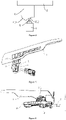
FIG. 1 is a schematic view of an inner handle for an automobile applied on a car door in an embodiment of the disclosure. -
FIG. 2 is a schematic structural view of the inner handle for the automobile in an embodiment of the disclosure. -
FIG. 3 is schematic structural view of a top view of the inner handle for the automobile in an embodiment of the disclosure. -
FIG. 4 is a schematic view of a first driving component of the inner handle for the automobile in an embodiment of the disclosure. -
FIG. 5 is a schematic structural view of a state of a triggered switch of the inner handle for the automobile in an embodiment of the disclosure. -
FIG. 6 is a schematic structural view of another state of a top view of the inner handle for the automobile in an embodiment of the disclosure. -
FIG. 7 is a schematic structural view of a pulling wire which is pulled in an embodiment of the inner handle for an automobile of the disclosure. - 1-handle, 2-base, 3-reset assembly, 301-pin shaft, 302-torsion spring, 4-switch, 5-contacting point, 6-first driving component, 601-protrusion, 602-notch, 7-pulling wire, 8-second driving component, 10-locking structure.
- The following describes the implementation of the disclosure through specific embodiments, and those skilled in the art can easily understand other advantages and effects of the disclosure from the content disclosed in this specification. The disclosure may also be implemented or applied through other different specific embodiments. Various details in this specification may also be modified or changed based on different viewpoints and applications without departing the subject-matter of the appending claims. It should be noted that following embodiments and features in the embodiments may be combined with each other under a condition of no conflict. It should also be understood that terms used in the embodiments of the disclosure are used to describe specific embodiments, rather than to limit a protection scope of the disclosure. In the following embodiments, test methods without specific conditions are usually in accordance with conventional conditions or in accordance with conditions suggested by various manufacturers.
- Please refer to
FIG. 1 . The disclosure provides an inner handle for an automobile, which may be arranged on a door body to drive the door body to be opened and closed. Alocking structure 10 is usually arranged between the door body and the vehicle body, and a connection between the vehicle body and the door body is realized through thelocking structure 10. Therefore, an unlocking and locking of thelocking structure 10 may be adjusted by driving the inner handle for automobiles, thereby driving an opening and closing of the door body. - Please refer to
FIG. 1 . In some embodiments, a specific structure of thelocking structure 10 may not be limited, for example, thelocking structure 10 may include a locking cylinder and a locking groove. A locking of thelocking structure 10 is realized by clamping the locking cylinder with the locking groove, and an unlocking of thelocking structure 10 is realized by separating the locking cylinder from the locking groove. And an unlocking method of thelocking structure 10 is not limited, for example, thelocking structure 10 may be unlocked by a mechanical module, or thelocking structure 10 may be unlocked by an electronic module. An unlocking of the mechanical module means that during an unlocking process of thelocking structure 10, thelocking structure 10 is driven by a mechanical mechanism of the mechanical module to realize the unlocking of thelocking structure 10. Therefore, during an unlocking process of the mechanical module, there is no additional power input. Further, an unlocking of the electronic module means that during the unlocking process of the lockingstructure 10, the lockingstructure 10 is driven by a circuit control of the electronic module to realize the unlocking of the lockingstructure 10. Therefore, during an unlocking process of the electronic module, there is no input from the mechanical module. By setting the lockingstructure 10 with multiple unlocking methods such as mechanical modules and electronic modules, an actual use effect of the lockingstructure 10 may be improved. - In some embodiments, the inner handle for automobile may be connected with the mechanical module and the electronic module at the same time. Therefore, by driving the inner handle for automobile, the unlocking and locking of the locking
structure 10 can be adjusted, thereby driving the opening and closing of the door body. - Please refer to
FIG. 2 . In some embodiments, the inner handle for automobile may include ahandle 1, abase 2 and areset assembly 3. Thebase 2 is connected with the door body, and thehandle 1 is rotatably connected with thebase 2. Apin shaft 301 may be connected with thebase 2, and a through hole may be arranged on thehandle 1. Therefore, thehandle 1 rotates relative to thepin shaft 301 by rotatably connecting the through hole on thehandle 1 with thepin shaft 301. Therefore, thehandle 1 may rotate relative to thepin shaft 301 to realize a rotational connection between thehandle 1 and thebase 2. Thereset assembly 3 is located between thehandle 1 and thebase 2, so when thehandle 1 rotates relative to thebase 2 by a certain angle, thereset assembly 3 is configured to reset thehandle 1. Therefore, after the door body is opened, thehandle 1 may be quickly reset through thereset assembly 3. A specific structure of thereset assembly 3 may not be limited. For example, in an embodiment, thereset assembly 3 may include atorsion spring 302. Specifically, thetorsion spring 302 is connected between thebase 2 and thehandle 1, so that thehandle 1 may be reset in time after rotating. - Please refer to
FIG. 3 through FIG. 5 . In some embodiments, thehandle 1 is connected with the electronic module, and the electronic module may include aswitch 4, a motor and afirst driving component 6. Theswitch 4 is connected with a control circuit of the motor, so the motor may be driven to rotate by triggering theswitch 4. A specific structure of theswitch 4 may not be limited. In one embodiment, theswitch 4 may be a micro switch. Therefore, through the micro switch, a triggering precision of theswitch 4 may be improved, so as to improve an actual use effect of the electronic module. Further, an output end of the motor is connected with the locking cylinder, so during a rotation of the motor, the locking cylinder may be driven to be separated from the locking groove. As long as the locking cylinder may be driven to move by the motor, a specific connection between the output end of the motor and the locking cylinder may not be limited. For example, in some embodiments, a rack may be connected to the locking cylinder, a gear is connected to the output end of the motor, and the gear and the rack are in a meshing connection. Therefore, through the rotation of the motor, the gear drives the rack to move, thereby driving the locking cylinder to move. Specifically, thefirst driving component 6 is connected with thehandle 1, and thefirst driving component 6 and thehandle 1 are fixedly connected with each other, so thefirst driving component 6 may rotate synchronously with thehandle 1. Therefore, when thefirst driving component 6 rotates, theswitch 4 is triggered to drive the motor to rotate, thereby driving the lock cylinder to move. In order to improve a practical use effect of thefirst driving component 6, in one embodiment, thefirst driving component 6 is provided with anotch 602 and aprotrusion 601. When thehandle 1 is in an non-rotating state, a contactingpoint 5 of theswitch 4 is located in thenotch 602, and there may be a certain gap between thefirst driving component 6 and the contactingpoint 5. Therefore, by setting the gap between thefirst driving component 6 and the contactingpoint 5, it is possible to avoid touching the micro switch by mistake, so as to improve the actual use effect of the electronic module. When thehandle 1 rotates at a certain angle, theprotrusion 601 is in contact with the contactingpoint 5 of theswitch 4 to trigger theswitch 4. Specifically, when theprotrusion 601 and theswitch 4 are triggered, a rotation angle of thehandle 1 may not be limited. For example, in one embodiment, when theprotrusion 601 and theswitch 4 are triggered, the rotation angle of thehandle 1 may be from 10 degrees to 20 degrees. - Please refer to
FIG. 6 andFIG. 7 . In some embodiments, thehandle 1 is connected with the mechanical module, and the mechanical module may include a pullingwire 7 and a second driving component 8. Wherein, one end of the pullingwire 7 is connected with the locking cylinder, and the locking cylinder may be driven to be separated from the locking groove by pulling the pullingwire 7. The other end of the pullingwire 7 is connected with the second driving component 8, so the pullingwire 7 may be pulled by driving the second driving component 8. Specifically, the second driving component 8 is connected on thehandle 1 and is fixedly connected with thehandle 1. During the rotation of thehandle 1, the second driving component 8 may rotate synchronously with thehandle 1. Therefore, when thehandle 1 rotates at a certain angle, the second driving component 8 pulls the pullingwire 7, and drives the locking cylinder to be separated from the locking groove through the pulling wire7. When the locking cylinder is driven to be separated from the locking groove by the pullingwire 7, the rotation angle of thehandle 1 may not be limited. For example, in one embodiment, when the pullingwire 7 drives the locking cylinder to be separated from the locking groove, the rotation angle of thehandle 1 may be at least 25 degrees. - Wherein, the
first driving component 6 and the second driving component 8 may also be set as an integral structure, so as to improve a utilization rate of a space of the inner handle for automobile. For example, in one embodiment, a driving component is connected with thehandle 1. The driving component is provided with theprotrusion 601 and thenotch 602, and the pullingwire 7 is also connected with the driving component. Therefore, when the door body is not opened, the contactingpoint 5 of the micro switch is located in thenotch 602. When thehandle 1 is opened at a certain angle, for example, when the angle is from 10 degrees to 20 degrees, theprotrusion 601 triggers the contactingpoint 5 of the micro switch. The contactingpoint 5 of the micro switch is triggered by theprotrusion 601 to turn on the motor and unlock the lockingstructure 10. Further, when thehandle 1 is continuously opened at a certain angle, for example, when the angle is greater than 25 degrees, the second driving component 8 pulls the pullingwire 7 and drives the locking cylinder to be separated from the locking groove through the pullingwire 7. The pullingwire 7 is pulled by the driving component 8 to realize an unlocking of the lockingstructure 10. - In summary, the disclosure provides the inner handle for automobile, which is provided with the micro switch of the electric door on the handle. In an opening process of the handle of the inner handle, first the micro switch is touched to realize an opening of the electric door. Then the handle continues to be pulled after touching the micro switch, in order to reach an unlocking state to achieve a mechanical unlocking. Therefore, by arranging an electric switch of a vehicle door in the inner handle, an additional electric switch is avoided, and the actual use effect of the inner handle is improved.
- The above-mentioned embodiments merely illustrate the principles and effects of the disclosure, but are not intended to limit the disclosure. Anyone skilled in the art may modify or change the above embodiments without departing from the range of the disclosure. Therefore, all equivalent modifications or changes made by those with ordinary knowledge in the technical field without departing from the range and technique disclosed in the disclosure should still be covered by the claims of the disclosure.
Claims (10)
- An inner handle for an automobile, comprising:a base,a handle, rotatably connected with the base,a reset assembly, located between the handle and the base, anda driving assembly, connected with the handle, comprising:an electronic module, comprising a switch and a first driving component, the first driving component configured to trigger the switch during a rotation of the handle, anda mechanical module, comprising a second driving component and a pulling wire, the second driving component configured to pull the pulling wire during the rotation of the handle.
- The inner handle for the automobile according to claim 1, further comprising a pin shaft, wherein,
the pin shaft is connected with the base, and the handle is rotatably connected on the pin shaft. - The inner handle for the automobile according to any preceding claims, wherein the reset assembly comprises a torsion spring, and the torsion spring is located between the handle and the base.
- The inner handle for the automobile according to any preceding claims, wherein the first driving component is connected with the handle.
- The inner handle for the automobile according to any preceding claims, wherein the first driving component comprises a protrusion and a notch.
- The inner handle for the automobile according to claim 5, wherein the switch comprises a contacting point, and the contacting point is located in the notch.
- The inner handle for the automobile according to any preceding claims, wherein the second driving component is connected with the handle.
- A car door, comprising:a door body,a locking structure, arranged on the door body, andan inner handle according to any one of claims 1 to 7,
the base being connected with the door body. - The car door according to claim 8, further comprising a motor, wherein
an output end of the motor is connected with the locking structure. - The car door according to claim 8 or claim 9, wherein
one end of the pulling wire is connected with the second driving component, and the other end of the pulling wire is connected with the locking structure.
Applications Claiming Priority (1)
| Application Number | Priority Date | Filing Date | Title |
|---|---|---|---|
| CN202122320670.XU CN218581385U (en) | 2021-09-24 | 2021-09-24 | Automobile inner buckle and automobile door applying same |
Publications (3)
| Publication Number | Publication Date |
|---|---|
| EP4155490A1 true EP4155490A1 (en) | 2023-03-29 |
| EP4155490C0 EP4155490C0 (en) | 2024-08-07 |
| EP4155490B1 EP4155490B1 (en) | 2024-08-07 |
Family
ID=82748216
Family Applications (1)
| Application Number | Title | Priority Date | Filing Date |
|---|---|---|---|
| EP22187331.8A Active EP4155490B1 (en) | 2021-09-24 | 2022-07-27 | Inner handle for automobile and application thereof |
Country Status (3)
| Country | Link |
|---|---|
| EP (1) | EP4155490B1 (en) |
| JP (1) | JP7389187B2 (en) |
| CN (1) | CN218581385U (en) |
Cited By (2)
| Publication number | Priority date | Publication date | Assignee | Title |
|---|---|---|---|---|
| CN117868611A (en) * | 2024-01-26 | 2024-04-12 | 上汽大众汽车有限公司 | Intelligent inner opening handle assembly of vehicle |
| CN121375010A (en) * | 2025-12-22 | 2026-01-23 | 浙江星泰模塑科技股份有限公司 | Automobile instrument frame injection mold and method |
Families Citing this family (1)
| Publication number | Priority date | Publication date | Assignee | Title |
|---|---|---|---|---|
| CN117846433A (en) * | 2023-12-25 | 2024-04-09 | 雷达新能源汽车(浙江)有限公司 | Door assembly and vehicle including the same |
Citations (4)
| Publication number | Priority date | Publication date | Assignee | Title |
|---|---|---|---|---|
| WO2013189695A1 (en) * | 2012-06-19 | 2013-12-27 | Bayerische Motoren Werke Aktiengesellschaft | Interior door opener for the door lock of a motor vehicle |
| DE202016106647U1 (en) * | 2016-11-29 | 2017-01-04 | Karl Heß GmbH & Co. KG Kunststoffverarbeitung | actuator |
| CN210563903U (en) * | 2019-05-24 | 2020-05-19 | 宁波华德汽车零部件有限公司 | Electronic mechanical double-unlocking structure of automobile inner handle |
| WO2021075301A1 (en) * | 2019-10-16 | 2021-04-22 | 株式会社ユーシン | Door opening/closing detection device and door opening/closing device |
Family Cites Families (3)
| Publication number | Priority date | Publication date | Assignee | Title |
|---|---|---|---|---|
| JP5293674B2 (en) * | 2010-04-22 | 2013-09-18 | アイシン精機株式会社 | Vehicle door lock device |
| JP5781025B2 (en) * | 2012-07-09 | 2015-09-16 | 株式会社ホンダロック | Unlatch device for vehicle door |
| WO2021182142A1 (en) * | 2020-03-13 | 2021-09-16 | アルプスアルパイン株式会社 | Vehicle door opener |
-
2021
- 2021-09-24 CN CN202122320670.XU patent/CN218581385U/en active Active
-
2022
- 2022-07-27 EP EP22187331.8A patent/EP4155490B1/en active Active
- 2022-08-10 JP JP2022127935A patent/JP7389187B2/en active Active
Patent Citations (4)
| Publication number | Priority date | Publication date | Assignee | Title |
|---|---|---|---|---|
| WO2013189695A1 (en) * | 2012-06-19 | 2013-12-27 | Bayerische Motoren Werke Aktiengesellschaft | Interior door opener for the door lock of a motor vehicle |
| DE202016106647U1 (en) * | 2016-11-29 | 2017-01-04 | Karl Heß GmbH & Co. KG Kunststoffverarbeitung | actuator |
| CN210563903U (en) * | 2019-05-24 | 2020-05-19 | 宁波华德汽车零部件有限公司 | Electronic mechanical double-unlocking structure of automobile inner handle |
| WO2021075301A1 (en) * | 2019-10-16 | 2021-04-22 | 株式会社ユーシン | Door opening/closing detection device and door opening/closing device |
Cited By (2)
| Publication number | Priority date | Publication date | Assignee | Title |
|---|---|---|---|---|
| CN117868611A (en) * | 2024-01-26 | 2024-04-12 | 上汽大众汽车有限公司 | Intelligent inner opening handle assembly of vehicle |
| CN121375010A (en) * | 2025-12-22 | 2026-01-23 | 浙江星泰模塑科技股份有限公司 | Automobile instrument frame injection mold and method |
Also Published As
| Publication number | Publication date |
|---|---|
| CN218581385U (en) | 2023-03-07 |
| EP4155490C0 (en) | 2024-08-07 |
| JP2023047291A (en) | 2023-04-05 |
| EP4155490B1 (en) | 2024-08-07 |
| JP7389187B2 (en) | 2023-11-29 |
Similar Documents
| Publication | Publication Date | Title |
|---|---|---|
| EP4155490B1 (en) | Inner handle for automobile and application thereof | |
| US10363799B2 (en) | Coach door of vehicle openable and closable regardless of order | |
| JP4583634B2 (en) | Vehicle door opening and closing device | |
| US8172303B2 (en) | Link mechanism | |
| KR20180071434A (en) | Switchger of tailgate for vehicle | |
| CN109458071A (en) | Engine hood lock and automobile | |
| KR20020041287A (en) | Door lock drive unit | |
| JP2015537132A (en) | Car door lock | |
| CN113266223B (en) | A scissor door hinge and vehicle | |
| CN109281557B (en) | Suction unlocking control device | |
| CN103527012B (en) | A kind of automobile tail gate lock and method of work | |
| CN109339617A (en) | Auto doors and cars | |
| KR20180072013A (en) | Switchger of tailgate for vehicle | |
| CN117328773A (en) | A vehicle charging port cover, control method, device and automobile | |
| CN117794774A (en) | Motor vehicle charging device | |
| CN210416258U (en) | Electronic lock with manual unlocking button, electric vehicle charging equipment and electric vehicle | |
| KR102764299B1 (en) | Ratch assembly for opening and closing of luggage room of vehicle | |
| CN220790923U (en) | Front cover electric lock | |
| CN215803834U (en) | Electromechanical separating mechanism for lock | |
| CN210798575U (en) | A Novel Angled Grasping Mechanism | |
| CN112360244B (en) | Automatic motor lock latch bolt toggle mechanism | |
| CN114562164A (en) | Lock device for sliding door of motor vehicle, sliding door of motor vehicle and motor vehicle | |
| CN208396472U (en) | Realize the mechanical gear structure with the independent open locking of intelligence | |
| CN223536174U (en) | A car door lock locking device | |
| CN117306965B (en) | A car door lock actuator mechanism with self-priming and interruption |
Legal Events
| Date | Code | Title | Description |
|---|---|---|---|
| PUAI | Public reference made under article 153(3) epc to a published international application that has entered the european phase |
Free format text: ORIGINAL CODE: 0009012 |
|
| STAA | Information on the status of an ep patent application or granted ep patent |
Free format text: STATUS: REQUEST FOR EXAMINATION WAS MADE |
|
| 17P | Request for examination filed |
Effective date: 20220823 |
|
| AK | Designated contracting states |
Kind code of ref document: A1 Designated state(s): AL AT BE BG CH CY CZ DE DK EE ES FI FR GB GR HR HU IE IS IT LI LT LU LV MC MK MT NL NO PL PT RO RS SE SI SK SM TR |
|
| RBV | Designated contracting states (corrected) |
Designated state(s): AL AT BE BG CH CY CZ DE DK EE ES FI FR GB GR HR HU IE IS IT LI LT LU LV MC MK MT NL NO PL PT RO RS SE SI SK SM TR |
|
| RIN1 | Information on inventor provided before grant (corrected) |
Inventor name: SHI, MIAO Inventor name: DING, SANLIN Inventor name: REN, ZHIPEI Inventor name: GAO, JIANG Inventor name: BI, YUANFEI |
|
| GRAP | Despatch of communication of intention to grant a patent |
Free format text: ORIGINAL CODE: EPIDOSNIGR1 |
|
| STAA | Information on the status of an ep patent application or granted ep patent |
Free format text: STATUS: GRANT OF PATENT IS INTENDED |
|
| INTG | Intention to grant announced |
Effective date: 20240415 |
|
| GRAS | Grant fee paid |
Free format text: ORIGINAL CODE: EPIDOSNIGR3 |
|
| GRAA | (expected) grant |
Free format text: ORIGINAL CODE: 0009210 |
|
| STAA | Information on the status of an ep patent application or granted ep patent |
Free format text: STATUS: THE PATENT HAS BEEN GRANTED |
|
| AK | Designated contracting states |
Kind code of ref document: B1 Designated state(s): AL AT BE BG CH CY CZ DE DK EE ES FI FR GB GR HR HU IE IS IT LI LT LU LV MC MK MT NL NO PL PT RO RS SE SI SK SM TR |
|
| REG | Reference to a national code |
Ref country code: GB Ref legal event code: FG4D |
|
| REG | Reference to a national code |
Ref country code: CH Ref legal event code: EP |
|
| REG | Reference to a national code |
Ref country code: IE Ref legal event code: FG4D |
|
| REG | Reference to a national code |
Ref country code: DE Ref legal event code: R096 Ref document number: 602022005119 Country of ref document: DE |
|
| U01 | Request for unitary effect filed |
Effective date: 20240813 |
|
| U07 | Unitary effect registered |
Designated state(s): AT BE BG DE DK EE FI FR IT LT LU LV MT NL PT RO SE SI Effective date: 20240902 |
|
| PG25 | Lapsed in a contracting state [announced via postgrant information from national office to epo] |
Ref country code: NO Free format text: LAPSE BECAUSE OF FAILURE TO SUBMIT A TRANSLATION OF THE DESCRIPTION OR TO PAY THE FEE WITHIN THE PRESCRIBED TIME-LIMIT Effective date: 20241107 |
|
| PG25 | Lapsed in a contracting state [announced via postgrant information from national office to epo] |
Ref country code: GR Free format text: LAPSE BECAUSE OF FAILURE TO SUBMIT A TRANSLATION OF THE DESCRIPTION OR TO PAY THE FEE WITHIN THE PRESCRIBED TIME-LIMIT Effective date: 20241108 Ref country code: PL Free format text: LAPSE BECAUSE OF FAILURE TO SUBMIT A TRANSLATION OF THE DESCRIPTION OR TO PAY THE FEE WITHIN THE PRESCRIBED TIME-LIMIT Effective date: 20240807 |
|
| PG25 | Lapsed in a contracting state [announced via postgrant information from national office to epo] |
Ref country code: IS Free format text: LAPSE BECAUSE OF FAILURE TO SUBMIT A TRANSLATION OF THE DESCRIPTION OR TO PAY THE FEE WITHIN THE PRESCRIBED TIME-LIMIT Effective date: 20241207 |
|
| PG25 | Lapsed in a contracting state [announced via postgrant information from national office to epo] |
Ref country code: HR Free format text: LAPSE BECAUSE OF FAILURE TO SUBMIT A TRANSLATION OF THE DESCRIPTION OR TO PAY THE FEE WITHIN THE PRESCRIBED TIME-LIMIT Effective date: 20240807 |
|
| PG25 | Lapsed in a contracting state [announced via postgrant information from national office to epo] |
Ref country code: RS Free format text: LAPSE BECAUSE OF FAILURE TO SUBMIT A TRANSLATION OF THE DESCRIPTION OR TO PAY THE FEE WITHIN THE PRESCRIBED TIME-LIMIT Effective date: 20241107 Ref country code: ES Free format text: LAPSE BECAUSE OF FAILURE TO SUBMIT A TRANSLATION OF THE DESCRIPTION OR TO PAY THE FEE WITHIN THE PRESCRIBED TIME-LIMIT Effective date: 20240807 |
|
| PG25 | Lapsed in a contracting state [announced via postgrant information from national office to epo] |
Ref country code: RS Free format text: LAPSE BECAUSE OF FAILURE TO SUBMIT A TRANSLATION OF THE DESCRIPTION OR TO PAY THE FEE WITHIN THE PRESCRIBED TIME-LIMIT Effective date: 20241107 Ref country code: PL Free format text: LAPSE BECAUSE OF FAILURE TO SUBMIT A TRANSLATION OF THE DESCRIPTION OR TO PAY THE FEE WITHIN THE PRESCRIBED TIME-LIMIT Effective date: 20240807 Ref country code: NO Free format text: LAPSE BECAUSE OF FAILURE TO SUBMIT A TRANSLATION OF THE DESCRIPTION OR TO PAY THE FEE WITHIN THE PRESCRIBED TIME-LIMIT Effective date: 20241107 Ref country code: IS Free format text: LAPSE BECAUSE OF FAILURE TO SUBMIT A TRANSLATION OF THE DESCRIPTION OR TO PAY THE FEE WITHIN THE PRESCRIBED TIME-LIMIT Effective date: 20241207 Ref country code: HR Free format text: LAPSE BECAUSE OF FAILURE TO SUBMIT A TRANSLATION OF THE DESCRIPTION OR TO PAY THE FEE WITHIN THE PRESCRIBED TIME-LIMIT Effective date: 20240807 Ref country code: GR Free format text: LAPSE BECAUSE OF FAILURE TO SUBMIT A TRANSLATION OF THE DESCRIPTION OR TO PAY THE FEE WITHIN THE PRESCRIBED TIME-LIMIT Effective date: 20241108 Ref country code: ES Free format text: LAPSE BECAUSE OF FAILURE TO SUBMIT A TRANSLATION OF THE DESCRIPTION OR TO PAY THE FEE WITHIN THE PRESCRIBED TIME-LIMIT Effective date: 20240807 |
|
| PG25 | Lapsed in a contracting state [announced via postgrant information from national office to epo] |
Ref country code: SM Free format text: LAPSE BECAUSE OF FAILURE TO SUBMIT A TRANSLATION OF THE DESCRIPTION OR TO PAY THE FEE WITHIN THE PRESCRIBED TIME-LIMIT Effective date: 20240807 |
|
| PG25 | Lapsed in a contracting state [announced via postgrant information from national office to epo] |
Ref country code: CZ Free format text: LAPSE BECAUSE OF FAILURE TO SUBMIT A TRANSLATION OF THE DESCRIPTION OR TO PAY THE FEE WITHIN THE PRESCRIBED TIME-LIMIT Effective date: 20240807 |
|
| PG25 | Lapsed in a contracting state [announced via postgrant information from national office to epo] |
Ref country code: SK Free format text: LAPSE BECAUSE OF FAILURE TO SUBMIT A TRANSLATION OF THE DESCRIPTION OR TO PAY THE FEE WITHIN THE PRESCRIBED TIME-LIMIT Effective date: 20240807 |
|
| PLBE | No opposition filed within time limit |
Free format text: ORIGINAL CODE: 0009261 |
|
| STAA | Information on the status of an ep patent application or granted ep patent |
Free format text: STATUS: NO OPPOSITION FILED WITHIN TIME LIMIT |
|
| U20 | Renewal fee for the european patent with unitary effect paid |
Year of fee payment: 4 Effective date: 20250527 |
|
| 26N | No opposition filed |
Effective date: 20250508 |
|
| REG | Reference to a national code |
Ref country code: CH Ref legal event code: H13 Free format text: ST27 STATUS EVENT CODE: U-0-0-H10-H13 (AS PROVIDED BY THE NATIONAL OFFICE) Effective date: 20260224 |
|
| PG25 | Lapsed in a contracting state [announced via postgrant information from national office to epo] |
Ref country code: CH Free format text: LAPSE BECAUSE OF NON-PAYMENT OF DUE FEES Effective date: 20250731 |