EP4155464A1 - Work machine - Google Patents
Work machine Download PDFInfo
- Publication number
- EP4155464A1 EP4155464A1 EP21809614.7A EP21809614A EP4155464A1 EP 4155464 A1 EP4155464 A1 EP 4155464A1 EP 21809614 A EP21809614 A EP 21809614A EP 4155464 A1 EP4155464 A1 EP 4155464A1
- Authority
- EP
- European Patent Office
- Prior art keywords
- arm
- link rod
- pin
- hydraulic cylinder
- working device
- Prior art date
- Legal status (The legal status is an assumption and is not a legal conclusion. Google has not performed a legal analysis and makes no representation as to the accuracy of the status listed.)
- Withdrawn
Links
Images


Classifications
-
- E—FIXED CONSTRUCTIONS
- E02—HYDRAULIC ENGINEERING; FOUNDATIONS; SOIL SHIFTING
- E02F—DREDGING; SOIL-SHIFTING
- E02F3/00—Dredgers; Soil-shifting machines
- E02F3/04—Dredgers; Soil-shifting machines mechanically-driven
- E02F3/96—Dredgers; Soil-shifting machines mechanically-driven with arrangements for alternate or simultaneous use of different digging elements
- E02F3/965—Dredgers; Soil-shifting machines mechanically-driven with arrangements for alternate or simultaneous use of different digging elements of metal-cutting or concrete-crushing implements
-
- E—FIXED CONSTRUCTIONS
- E02—HYDRAULIC ENGINEERING; FOUNDATIONS; SOIL SHIFTING
- E02F—DREDGING; SOIL-SHIFTING
- E02F3/00—Dredgers; Soil-shifting machines
- E02F3/04—Dredgers; Soil-shifting machines mechanically-driven
- E02F3/28—Dredgers; Soil-shifting machines mechanically-driven with digging tools mounted on a dipper- or bucket-arm, i.e. there is either one arm or a pair of arms, e.g. dippers, buckets
- E02F3/30—Dredgers; Soil-shifting machines mechanically-driven with digging tools mounted on a dipper- or bucket-arm, i.e. there is either one arm or a pair of arms, e.g. dippers, buckets with a dipper-arm pivoted on a cantilever beam, i.e. boom
- E02F3/308—Dredgers; Soil-shifting machines mechanically-driven with digging tools mounted on a dipper- or bucket-arm, i.e. there is either one arm or a pair of arms, e.g. dippers, buckets with a dipper-arm pivoted on a cantilever beam, i.e. boom working outwardly
-
- E—FIXED CONSTRUCTIONS
- E02—HYDRAULIC ENGINEERING; FOUNDATIONS; SOIL SHIFTING
- E02F—DREDGING; SOIL-SHIFTING
- E02F3/00—Dredgers; Soil-shifting machines
- E02F3/04—Dredgers; Soil-shifting machines mechanically-driven
- E02F3/28—Dredgers; Soil-shifting machines mechanically-driven with digging tools mounted on a dipper- or bucket-arm, i.e. there is either one arm or a pair of arms, e.g. dippers, buckets
- E02F3/30—Dredgers; Soil-shifting machines mechanically-driven with digging tools mounted on a dipper- or bucket-arm, i.e. there is either one arm or a pair of arms, e.g. dippers, buckets with a dipper-arm pivoted on a cantilever beam, i.e. boom
- E02F3/32—Dredgers; Soil-shifting machines mechanically-driven with digging tools mounted on a dipper- or bucket-arm, i.e. there is either one arm or a pair of arms, e.g. dippers, buckets with a dipper-arm pivoted on a cantilever beam, i.e. boom working downwardly and towards the machine, e.g. with backhoes
-
- E—FIXED CONSTRUCTIONS
- E02—HYDRAULIC ENGINEERING; FOUNDATIONS; SOIL SHIFTING
- E02F—DREDGING; SOIL-SHIFTING
- E02F3/00—Dredgers; Soil-shifting machines
- E02F3/04—Dredgers; Soil-shifting machines mechanically-driven
- E02F3/28—Dredgers; Soil-shifting machines mechanically-driven with digging tools mounted on a dipper- or bucket-arm, i.e. there is either one arm or a pair of arms, e.g. dippers, buckets
- E02F3/36—Component parts
- E02F3/38—Cantilever beams, i.e. booms;, e.g. manufacturing processes, forms, geometry or materials used for booms; Dipper-arms, e.g. manufacturing processes, forms, geometry or materials used for dipper-arms; Bucket-arms
-
- E—FIXED CONSTRUCTIONS
- E02—HYDRAULIC ENGINEERING; FOUNDATIONS; SOIL SHIFTING
- E02F—DREDGING; SOIL-SHIFTING
- E02F3/00—Dredgers; Soil-shifting machines
- E02F3/04—Dredgers; Soil-shifting machines mechanically-driven
- E02F3/28—Dredgers; Soil-shifting machines mechanically-driven with digging tools mounted on a dipper- or bucket-arm, i.e. there is either one arm or a pair of arms, e.g. dippers, buckets
- E02F3/36—Component parts
- E02F3/40—Dippers; Buckets ; Grab devices, e.g. manufacturing processes for buckets, form, geometry or material of buckets
-
- E—FIXED CONSTRUCTIONS
- E02—HYDRAULIC ENGINEERING; FOUNDATIONS; SOIL SHIFTING
- E02F—DREDGING; SOIL-SHIFTING
- E02F3/00—Dredgers; Soil-shifting machines
- E02F3/04—Dredgers; Soil-shifting machines mechanically-driven
- E02F3/28—Dredgers; Soil-shifting machines mechanically-driven with digging tools mounted on a dipper- or bucket-arm, i.e. there is either one arm or a pair of arms, e.g. dippers, buckets
- E02F3/36—Component parts
- E02F3/42—Drives for dippers, buckets, dipper-arms or bucket-arms
- E02F3/425—Drive systems for dipper-arms, backhoes or the like
-
- E—FIXED CONSTRUCTIONS
- E04—BUILDING
- E04G—SCAFFOLDING; FORMS; SHUTTERING; BUILDING IMPLEMENTS OR AIDS, OR THEIR USE; HANDLING BUILDING MATERIALS ON THE SITE; REPAIRING, BREAKING-UP OR OTHER WORK ON EXISTING BUILDINGS
- E04G23/00—Working measures on existing buildings
- E04G23/08—Wrecking of buildings
-
- E—FIXED CONSTRUCTIONS
- E04—BUILDING
- E04G—SCAFFOLDING; FORMS; SHUTTERING; BUILDING IMPLEMENTS OR AIDS, OR THEIR USE; HANDLING BUILDING MATERIALS ON THE SITE; REPAIRING, BREAKING-UP OR OTHER WORK ON EXISTING BUILDINGS
- E04G23/00—Working measures on existing buildings
- E04G23/08—Wrecking of buildings
- E04G23/082—Wrecking of buildings using shears, breakers, jaws and the like
-
- E—FIXED CONSTRUCTIONS
- E02—HYDRAULIC ENGINEERING; FOUNDATIONS; SOIL SHIFTING
- E02F—DREDGING; SOIL-SHIFTING
- E02F3/00—Dredgers; Soil-shifting machines
- E02F3/04—Dredgers; Soil-shifting machines mechanically-driven
- E02F3/28—Dredgers; Soil-shifting machines mechanically-driven with digging tools mounted on a dipper- or bucket-arm, i.e. there is either one arm or a pair of arms, e.g. dippers, buckets
- E02F3/36—Component parts
- E02F3/3604—Devices to connect tools to arms, booms or the like
- E02F3/3677—Devices to connect tools to arms, booms or the like allowing movement, e.g. rotation or translation, of the tool around or along another axis as the movement implied by the boom or arms, e.g. for tilting buckets
- E02F3/3681—Rotators
-
- E—FIXED CONSTRUCTIONS
- E02—HYDRAULIC ENGINEERING; FOUNDATIONS; SOIL SHIFTING
- E02F—DREDGING; SOIL-SHIFTING
- E02F3/00—Dredgers; Soil-shifting machines
- E02F3/04—Dredgers; Soil-shifting machines mechanically-driven
- E02F3/28—Dredgers; Soil-shifting machines mechanically-driven with digging tools mounted on a dipper- or bucket-arm, i.e. there is either one arm or a pair of arms, e.g. dippers, buckets
- E02F3/36—Component parts
- E02F3/40—Dippers; Buckets ; Grab devices, e.g. manufacturing processes for buckets, form, geometry or material of buckets
- E02F3/401—Buckets or forks comprising, for example, shock absorbers, supports or load striking scrapers to prevent overload
Definitions
- the present invention relates to a work machine equipped with a heavy attachment.
- a hydraulic excavator comprising a boom supported on an upperstructure so as to be raised and lowered, an arm rotatably supported at the distal end of the boom, and an attachment (for example, bucket) rotatably supported at the distal end of the arm (for example, see Patent Literature 1).
- the attachment operates in the gravity direction in accordance with the extension of a hydraulic cylinder supported on the back of the arm, and operates in the direction opposite to the gravity direction in accordance with the contraction of the hydraulic cylinder.
- Patent Literature 1 JP-A-2020-26782
- an object of the present invention is to provide a work machine capable of rotating an attachment while appropriately supporting a load applied to the attachment.
- the present invention provides a work machine comprising: an undercarriage; an upperstructure supported on the undercarriage so as to turn thereon; a front working device including a boom supported on the upperstructure so as to be raised and lowered, an arm rotatably supported at a distal end of the boom, and an attachment rotatably supported at a distal end of the arm, wherein the arm includes: a pair of side surfaces that faces each other in a width direction of the front working device; and a body side surface and a back side surface that face each other in a direction perpendicular to the width direction of the front working device, each of which is connected to ends of the pair of side surfaces, the front working device includes: a hydraulic cylinder that is attached to the body side surface of the arm, and is supplied with and discharges hydraulic oil to extend and contract; and a link mechanism configured to cause the attachment to dump when the hydraulic cylinder extends and cause the attachment to crowd when the hydraulic cylinder contracts, the linkage mechanism includes: a first link
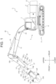
- FIG. 1 is a side view of a work machine 1 according to the present invention.
- the front, rear, left, and right are refereed based on the viewpoint of an operator who boards and operates the work machine 1 unless otherwise noted.
- the work machine 1 includes an undercarriage 2 and an upperstructure 3 supported on the undercarriage 2.
- the undercarriage 2 includes a pair of left and right crawlers 8. When the rotation of a traveling motor (not illustrated) is transmitted to the pair of left and right crawlers 8, the pair of left and right crawlers 8 rotates in accordance therewith, whereby the work machine 1 can travel.
- the undercarriage 2 may be a wheel-mounted type undercarriage instead of including the crawlers 8.
- the upperstructure 3 is supported on the undercarriage 2 so as to turn thereon.
- the upperstructure 3 mainly includes a turn frame 5 serving as a base, a cab (operator's seat) 7 arranged at the front left side of the turn frame 5, a front working device 10 mounted at the center of the front end of the turn frame 5 so as to rotate in the vertical direction, and a counterweight 6 arranged at the rear of the turn frame 5 to balance the weight between the front working device 10 and the upperstructure 3.
- a seat (not illustrated) on which the operator sits and operation devices (steering, pedal, lever, switch, etc.) which are operated by the operator sitting on the seat are arranged.
- the operator who is boarding the cab 7 operates the operation devices, whereby the undercarriage 2 travels, the upperstructure 3 turns, and the front working device 10 operates.
- the front working device 10 includes a boom 11 supported on the upperstructure 3 so as to be raised and lowered, an arm 12 rotatably supported at the distal end of the boom 11, a cutter (attachment) 13 rotatably supported at the distal end of the arm 12, hydraulic cylinders 14, 15, 16 for driving the boom 11, the arm 12, and the cutter 13, a link mechanism 17, and a stopper 18 (see FIG. 2 ).
- the arm 12 has a body side surface 12a, a back side surface 12b, a left side surface 12c (side surface), and a right side surface (not illustrated).
- the body side surface 12a and the back side surface 12b face each other in a direction perpendicular to the lateral direction (width direction of the front working device 10).
- the left side surface 12c and the right side surface face each other in the lateral direction.
- Each of the body side surface 12a and the back side surface 12b is connected to the end portions of the left side surface 12c and right side surface.
- the work machine 1 equipped with the cutter 13 works with the distal end of the arm 12 positioned forward of the distal end of the boom 11 (that is, with the body side surface 12a facing downward and the back side surface 12b facing upward).
- the cutter 13 is one of the examples of a demolition attachment designed to grasp and destroy an object (for example, buildings). As described later, the cutter 13 has the number of components, and also includes hydraulic actuators (a turn motor 13b, hydraulic cylinders 13e, 13f), and thus the cutter 13 is heavier than other attachments such as a bucket.
- the cutter 13 mainly includes a mounting bracket 13a, the turn motor 13b, a pair of blades 13c, 13d, and a pair of hydraulic cylinders 13e, 13f.
- the mounting bracket 13a is rotatably supported at the distal end of the arm 12 via a pin 13g extending in the lateral direction (width direction of the front working device 10). Furthermore, the mounting bracket 13a is rotatably connected to one end of a link rod 17a, which will be described later, via a pin 13h extending in the lateral direction.
- the pin 13h is arranged closer to the back surface side 12b of the arm 12 than the pin 13g. In other words, in the working attitude of the front working device 10, the pin 13h is arranged above the pin 13g.
- the turn motor 13b When the hydraulic oil is supplied to and discharged from the turn motor 13b, the turn motor 13b rotates the components 13c to 13f with respect to the mounting bracket 13a.
- the turn motor 13b rotates the components 13c to 13f about a rotation axis extending in a direction perpendicular to the pins 13g, 13h.
- the hydraulic oil is supplied from a hydraulic pump (not illustrated) mounted on the upperstructure 3 to the turn motor 13b, and returns to a hydraulic oil tank (not illustrated) mounted on the upperstructure 3 from the turn motor 13b.
- the pair of hydraulic cylinders 13e, 13f is supplied with the hydraulic oil, whereby the pair of blades 13c, 13d is opened and closed. More particularly, when the hydraulic oil is supplied to bottom chambers of the hydraulic cylinders 13e, 13f and the hydraulic oil in rod chambers thereof is discharged, the pair of blades 13c, 13d is closed. On the other hand, when the hydraulic oil is supplied to the rod chambers of the hydraulic cylinders 13e, 13f and the hydraulic oil in the bottom chambers is discharged, the pair of blades 13c, 13d is opened.
- the hydraulic cylinder 16 is supplied with and discharges the hydraulic oil, and extends and contracts in accordance therewith.
- the hydraulic cylinder 16 has a cylinder tube 16a, a piston (not illustrated), a cylinder rod 16b, and a cap 16c.
- the hydraulic cylinder 16 extends along the back side surface of the arm 12 in the longitudinal direction of the arm 12.
- the proximal end of the cylinder tube 16a is rotatably supported at the proximal end side of the arm 12, and the distal end of the cylinder rod 16b is rotatably connected to a link rod 17b, which will be described later.
- the cylinder tube 16a is a cylindrical member capable of being supplied with and discharging the hydraulic oil.
- the cylinder tube 16a is closed at the proximal end side and opened at the distal end side.
- the piston reciprocates within the cylinder tube 16a. Furthermore, the piston divides the internal space of the cylinder tube 16a into a bottom chamber at the proximal end side and a rod chamber at the cap 16c side.
- the cap 16c is attached to the distal end of the cylinder tube 16a via a bolt (not illustrated) or the like.
- the cap 16c includes a through hole for allowing the cylinder rod 16b to project while preventing the piston from projecting.
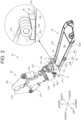
- FIG. 2 is a perspective view of the arm 12 and cutter 13.
- the link mechanism 17 is connected to the cutter 13 and the hydraulic cylinder 16.
- the link mechanism 17 rotates the cutter 13 with respect to the arm 12 in accordance with the extension and contraction of the hydraulic cylinder 16.
- the link mechanism 17 has a long bar-shaped link rod 17a (first link rod), a pair of long bar-shaped link rods 17b (second link rod), and pins 17c, 17d, 17e (first pin, second pin, third pin) extending in the lateral direction.
- the link rod 17a is arranged at the back side surface 12b side of the arm 12.
- the link rod 17a extends along the back side surface 12b of the arm 12.
- the link rod 17a is not necessarily parallel to the back side surface 12b.
- One end of the link rod 17a is rotatably connected to the mounting bracket 13a via the pin 13h.
- the other end of the link rod 17a is rotatably connected to each one end of the pair of link rods 17b via the pin 17d.
- the pair of link rods 17b is rotatably supported on the left side surface 12c and right side surface of the arm 12, respectively, via the pin 17c.
- one end thereof projects toward the back side surface 12b of the arm 12, and the other end thereof projects toward the body side surface 12a of the arm 12.
- the one end of the pair of link rods 17b (end portion at the back side surface 12b side) is rotatably connected to the other end of the link rod 17a via the pin 17d.
- the other end of the pair of link rods 17b (end portion at the body side surface 12a side) is rotatably connected to the distal end of the cylinder rod 16b via the pin 17e.
- a distance A between the pin 17c and the pin 17e is set equal to or more than a distance B between the pin 17c and the pin 17d (A ⁇ B).
- the stopper 18 is fixed to the back side surface 12b of the arm 12.
- the stopper 18 is fixed to the back side surface 12b at a position where the other end of the link rod 17a abuts when the hydraulic cylinder 16 extends.
- the top surface of the stopper 18 has a concave shape so as to be along the other end of the link rod 17a.
- FIG. 3 illustrates an attitude of the cutter 13 when the hydraulic cylinder contacts.
- the link rod 17b rotates counterclockwise in FIG. 3 about the pin 17c.
- the link rod 17b rotates about the pin 17c such that the end porion at the back side surface 12b side moves toward the distal end side of the arm 12 and the end portion at the body side surface 12a side moves toward the proximal end side of the arm 12.
- the link rod 17a moves in a direction for pushing the cutter 13 at the position of the pin 13h (that is, above the pin 13g).
- the cutter 13 rotates in a direction indicated by an arrow in FIG. 3 (that is, crowd operation).
- the “crowd operation” is an operation for rotating the cutter 13 toward the body side surface 12a of the arm 12. Then, while the distal end of the arm 12 is positioned forward of the distal end of the boom 11, by the crowd operation, the cutter 13 rotates in the gravity direction.
- FIG. 4 illustrates an attitude of the cutter 13 when the hydraulic cylinder extends.
- the link rod 17b rotates clockwise in FIG. 3 about the pin 17c.
- the link rod 17b rotates about the pin 17c such that the end portion at the back side surface 12b side moves toward the proximal end side of the arm 12 and the end portion at the body side surface 12a side moves toward the distal end side of the arm 12.
- the link rod 17a moves in a direction for pulling the cutter 13 at the position of the pin 13h (that is, above the pin 13g).
- the cutter 13 rotates in a direction indicated by an arrow in FIG. 4 (that is, dump operation).
- the "dump operation” is an operation for rotating the cutter 13 toward the body side surface 12a of the arm 12. Then, while the distal end of the arm 12 is positioned forward of the distal end of the boom 11, by the dump operation, the cutter 13 rotates in a direction opposite to the gravity direction (hereinafter, referred to as an "antigravity direction").
- the other end of the link rod 17a abuts the stopper 18 just when the hydraulic cylinder 16 extends to the maximum or immediately therebefore (that is, just before the hydraulic cylinder 16 extends to the maximum).
- the hydraulic cylinder 16 extends to the maximum is, for example, when the piston gets abutted the inner surface of the cap 16c. This prevents the cutter 13 from further rotating in the antigravity direction. As a result, a force in the direction for causing the hydraulic cylinder 16 to further extend is blocked from being transmitted from the cutter 13 to the hydraulic cylinder 16 through the link mechanism 17.
- the pressure receiving area at the bottom side of the piston is larger than the pressure receiving area at the rod side thereof to which the cylinder rod 16b is connected. Furthermore, as compared with the case where an amount of projection of the cylinder rod 16b is large, in the case where the amount of projection of the cylinder rod 16b is small, the hydraulic cylinder 16 can stably hold a load.
- the hydraulic cylinder 16 contracts in order to cause the cutter 13 to perform the crowd operation, it is possible to hold the cutter 13 with a large force as compared with the case where the cutter 13 is held while the hydraulic cylinder 16 extends. Therefore, in the work performed while the distal end of the arm 12 projects forward of the distal end of the boom 11, even if an unexpected load is applied to the cutter 13 and thus the cutter 13 nearly rotates further toward the body side surface 12a of the arm 12, the hydraulic cylinder 16 can stably support the cutter 13 with a sufficiently large force.
- the link rods 17a, 17b are elastically deformed by a load exerted thereto. Therefore, the link mechanism 17 also functions as a cushioning material for absorbing the load applied to the cutter 13 and preventing the load from being transmitted to the hydraulic cylinder 16. That is, according to the embodiment described above, it is possible to reduce the load applied from the cutter 13 to the hydraulic cylinder 16.
- the distance A between the pin 17c and the pin 17e is set to be equal to or more than the distance B between the pin 17c and the pin 17d, a force generated by the hydraulic cylinder 16 can be increased and transmitted to the cutter 13. As a result, it is possible to support the load acting on the cutter 13 more appropriately.
- the link rod 17a abuts the stopper 18 before the hydraulic cylinder 16 extends to the maximum.
- the force in the direction for causing the hydraulic cylinder 16 to further extend can be prevented from being transmitted from the cutter 13 to the hydraulic cylinder 16 through the link mechanism 17.
- the cutter 13 has been described as one of the examples of attachments, however, a specific example of the attachments is not limited thereto.
- the attachment may be a hanging attachment having a hook for hanging a material to be hung. It should be noted that the present invention can be applied to the work machine 1 equipped with a heavy attachment, thereby achieving particularly advantageous effects.
Landscapes
- Engineering & Computer Science (AREA)
- Mechanical Engineering (AREA)
- Structural Engineering (AREA)
- Architecture (AREA)
- Civil Engineering (AREA)
- Mining & Mineral Resources (AREA)
- General Engineering & Computer Science (AREA)
- Chemical & Material Sciences (AREA)
- Chemical Kinetics & Catalysis (AREA)
- Electrochemistry (AREA)
- Shovels (AREA)
- Working Measures On Existing Buildindgs (AREA)
Abstract
Description
- The present invention relates to a work machine equipped with a heavy attachment.
- Conventionally, there has been known a hydraulic excavator comprising a boom supported on an upperstructure so as to be raised and lowered, an arm rotatably supported at the distal end of the boom, and an attachment (for example, bucket) rotatably supported at the distal end of the arm (for example, see Patent Literature 1).
- In the hydraulic excavator configured as above, generally, the attachment operates in the gravity direction in accordance with the extension of a hydraulic cylinder supported on the back of the arm, and operates in the direction opposite to the gravity direction in accordance with the contraction of the hydraulic cylinder.
- Patent Literature 1:
JP-A-2020-26782 - However, when the attachment that is performing a crowd operation is held by the hydraulic cylinder with a rod thereof extending, a large load is applied on the hydraulic cylinder. This problem would be remarkable as the weight of the attachment increases.
- Therefore, an object of the present invention is to provide a work machine capable of rotating an attachment while appropriately supporting a load applied to the attachment.
- In order to achieve the object described above, the present invention provides a work machine comprising: an undercarriage; an upperstructure supported on the undercarriage so as to turn thereon; a front working device including a boom supported on the upperstructure so as to be raised and lowered, an arm rotatably supported at a distal end of the boom, and an attachment rotatably supported at a distal end of the arm, wherein the arm includes: a pair of side surfaces that faces each other in a width direction of the front working device; and a body side surface and a back side surface that face each other in a direction perpendicular to the width direction of the front working device, each of which is connected to ends of the pair of side surfaces, the front working device includes: a hydraulic cylinder that is attached to the body side surface of the arm, and is supplied with and discharges hydraulic oil to extend and contract; and a link mechanism configured to cause the attachment to dump when the hydraulic cylinder extends and cause the attachment to crowd when the hydraulic cylinder contracts, the linkage mechanism includes: a first link rod that extends along the back side surface of the arm; a second link rod that is rotatably supported on the side surfaces of the arm via a first pin extending in the width direction of the front working device, the second link rod having one end which projects toward the back side surface of the arm and the other end which projects toward the body side surface of the arm, one end of the first link rod is rotatably connected to the attachment, the one end of the second link rod is rotatably connected to the other end of the first link rod via a second pin extending in the width direction of the front working device, and the other end of the second link rod is rotatably connected to a distal end of a cylinder rod of the hydraulic cylinder via a third pin extending in the width direction of the front working device.
- According to the present invention, it is possible to rotate an attachment while appropriately supporting a load applied to the attachment. The problems, configurations, and advantageous effects other than those described above will be clarified by explanation of an embodiment below.
-
- [
FIG. 1] FIG. 1 is a side view of a work machine according to the present invention. - [
FIG. 2] FIG. 2 is a perspective view of an arm and cutter. - [
FIG. 3] FIG. 3 illustrates an attitude of the cutter when a hydraulic cylinder contracts. - [
FIG. 4] FIG. 4 illustrates an attitude of the cutter when the hydraulic cylinder extends. - An embodiment of a work machine according to the present invention will be described with reference to the drawings.
FIG. 1 is a side view of awork machine 1 according to the present invention. In the present specification, the front, rear, left, and right are refereed based on the viewpoint of an operator who boards and operates thework machine 1 unless otherwise noted. - The
work machine 1 includes anundercarriage 2 and anupperstructure 3 supported on theundercarriage 2. Theundercarriage 2 includes a pair of left andright crawlers 8. When the rotation of a traveling motor (not illustrated) is transmitted to the pair of left andright crawlers 8, the pair of left andright crawlers 8 rotates in accordance therewith, whereby thework machine 1 can travel. Note that theundercarriage 2 may be a wheel-mounted type undercarriage instead of including thecrawlers 8. - The
upperstructure 3 is supported on theundercarriage 2 so as to turn thereon. Theupperstructure 3 mainly includes a turn frame 5 serving as a base, a cab (operator's seat) 7 arranged at the front left side of the turn frame 5, afront working device 10 mounted at the center of the front end of the turn frame 5 so as to rotate in the vertical direction, and acounterweight 6 arranged at the rear of the turn frame 5 to balance the weight between thefront working device 10 and theupperstructure 3. - In the
cab 7, an internal space where an operator who operates theworking machine 1 boards is formed. Inside thecab 7, a seat (not illustrated) on which the operator sits and operation devices (steering, pedal, lever, switch, etc.) which are operated by the operator sitting on the seat are arranged. The operator who is boarding thecab 7 operates the operation devices, whereby theundercarriage 2 travels, theupperstructure 3 turns, and thefront working device 10 operates. - The
front working device 10 includes aboom 11 supported on theupperstructure 3 so as to be raised and lowered, anarm 12 rotatably supported at the distal end of theboom 11, a cutter (attachment) 13 rotatably supported at the distal end of thearm 12,hydraulic cylinders boom 11, thearm 12, and thecutter 13, alink mechanism 17, and a stopper 18 (seeFIG. 2 ). - The
arm 12 has abody side surface 12a, aback side surface 12b, aleft side surface 12c (side surface), and a right side surface (not illustrated). Thebody side surface 12a and theback side surface 12b face each other in a direction perpendicular to the lateral direction (width direction of the front working device 10). Theleft side surface 12c and the right side surface (a pair of side surfaces) face each other in the lateral direction. Each of thebody side surface 12a and theback side surface 12b is connected to the end portions of theleft side surface 12c and right side surface. - In particular, when the distal end of the
arm 12 is positioned forward of the distal end of the boom 11 (when thehydraulic cylinder 15 contracts to some extent), thebody side surface 12a faces downward and theback side surface 12b faces upward. In general, thework machine 1 equipped with thecutter 13 works with the distal end of thearm 12 positioned forward of the distal end of the boom 11 (that is, with thebody side surface 12a facing downward and theback side surface 12b facing upward). - The
cutter 13 is one of the examples of a demolition attachment designed to grasp and destroy an object (for example, buildings). As described later, thecutter 13 has the number of components, and also includes hydraulic actuators (aturn motor 13b,hydraulic cylinders cutter 13 is heavier than other attachments such as a bucket. Thecutter 13 mainly includes amounting bracket 13a, theturn motor 13b, a pair ofblades hydraulic cylinders - The
mounting bracket 13a is rotatably supported at the distal end of thearm 12 via apin 13g extending in the lateral direction (width direction of the front working device 10). Furthermore, themounting bracket 13a is rotatably connected to one end of alink rod 17a, which will be described later, via apin 13h extending in the lateral direction. Thepin 13h is arranged closer to theback surface side 12b of thearm 12 than thepin 13g. In other words, in the working attitude of thefront working device 10, thepin 13h is arranged above thepin 13g. - When the hydraulic oil is supplied to and discharged from the
turn motor 13b, theturn motor 13b rotates thecomponents 13c to 13f with respect to themounting bracket 13a. Theturn motor 13b rotates thecomponents 13c to 13f about a rotation axis extending in a direction perpendicular to thepins upperstructure 3 to theturn motor 13b, and returns to a hydraulic oil tank (not illustrated) mounted on theupperstructure 3 from theturn motor 13b. - The pair of
hydraulic cylinders blades hydraulic cylinders blades hydraulic cylinders blades - The
hydraulic cylinder 16 is supplied with and discharges the hydraulic oil, and extends and contracts in accordance therewith. Thehydraulic cylinder 16 has acylinder tube 16a, a piston (not illustrated), acylinder rod 16b, and acap 16c. Thehydraulic cylinder 16 extends along the back side surface of thearm 12 in the longitudinal direction of thearm 12. In thehydraulic cylinder 16, the proximal end of thecylinder tube 16a is rotatably supported at the proximal end side of thearm 12, and the distal end of thecylinder rod 16b is rotatably connected to alink rod 17b, which will be described later. - The
cylinder tube 16a is a cylindrical member capable of being supplied with and discharging the hydraulic oil. Thecylinder tube 16a is closed at the proximal end side and opened at the distal end side. The piston reciprocates within thecylinder tube 16a. Furthermore, the piston divides the internal space of thecylinder tube 16a into a bottom chamber at the proximal end side and a rod chamber at thecap 16c side. - One end of the
cylinder rod 16b is connected to the piston, and the other end projects to the outside of thecylinder tube 16a passing through thecap 16c. Thecap 16c is attached to the distal end of thecylinder tube 16a via a bolt (not illustrated) or the like. Thecap 16c includes a through hole for allowing thecylinder rod 16b to project while preventing the piston from projecting. - When the hydraulic oil is supplied from the hydraulic pump to the bottom chamber and the hydraulic oil in the rod chamber returns to the hydraulic oil tank, the piston moves in a direction for causing the
cylinder rod 16b to project from thecylinder tube 16a (hereinafter, this operational action is referred to as "extension of thehydraulic cylinder 16"). On the other hand, when the hydraulic oil is supplied from the hydraulic pump to the rod chamber and the hydraulic oil in the bottom chamber returns to the hydraulic oil tank, the piston moves in a direction for withdrawing thecylinder rod 16b into thecylinder tube 16a (hereinafter, this operational action is referred to as "contraction of thehydraulic cylinder 16"). -
FIG. 2 is a perspective view of thearm 12 andcutter 13. Thelink mechanism 17 is connected to thecutter 13 and thehydraulic cylinder 16. Thelink mechanism 17 rotates thecutter 13 with respect to thearm 12 in accordance with the extension and contraction of thehydraulic cylinder 16. As illustrated inFIG. 1 andFIG. 2 , thelink mechanism 17 has a long bar-shapedlink rod 17a (first link rod), a pair of long bar-shapedlink rods 17b (second link rod), and pins 17c, 17d, 17e (first pin, second pin, third pin) extending in the lateral direction. - The
link rod 17a is arranged at theback side surface 12b side of thearm 12. Thelink rod 17a extends along theback side surface 12b of thearm 12. Here, thelink rod 17a is not necessarily parallel to theback side surface 12b. One end of thelink rod 17a is rotatably connected to the mountingbracket 13a via thepin 13h. The other end of thelink rod 17a is rotatably connected to each one end of the pair oflink rods 17b via thepin 17d. - The pair of
link rods 17b is rotatably supported on theleft side surface 12c and right side surface of thearm 12, respectively, via thepin 17c. In each of the pair oflink rods 17b, one end thereof projects toward theback side surface 12b of thearm 12, and the other end thereof projects toward thebody side surface 12a of thearm 12. The one end of the pair oflink rods 17b (end portion at theback side surface 12b side) is rotatably connected to the other end of thelink rod 17a via thepin 17d. The other end of the pair oflink rods 17b (end portion at thebody side surface 12a side) is rotatably connected to the distal end of thecylinder rod 16b via thepin 17e. Furthermore, as illustrated inFIG. 3 , a distance A between thepin 17c and thepin 17e is set equal to or more than a distance B between thepin 17c and thepin 17d (A≥B). - Furthermore, as illustrated in
FIG. 2 , thestopper 18 is fixed to theback side surface 12b of thearm 12. Thestopper 18 is fixed to theback side surface 12b at a position where the other end of thelink rod 17a abuts when thehydraulic cylinder 16 extends. The top surface of thestopper 18 has a concave shape so as to be along the other end of thelink rod 17a. -
FIG. 3 illustrates an attitude of thecutter 13 when the hydraulic cylinder contacts. When thehydraulic cylinder 16 contracts, thelink rod 17b rotates counterclockwise inFIG. 3 about thepin 17c. In other words, thelink rod 17b rotates about thepin 17c such that the end porion at theback side surface 12b side moves toward the distal end side of thearm 12 and the end portion at thebody side surface 12a side moves toward the proximal end side of thearm 12. - Thus, the
link rod 17a moves in a direction for pushing thecutter 13 at the position of thepin 13h (that is, above thepin 13g). As a result, thecutter 13 rotates in a direction indicated by an arrow inFIG. 3 (that is, crowd operation). The "crowd operation" is an operation for rotating thecutter 13 toward thebody side surface 12a of thearm 12. Then, while the distal end of thearm 12 is positioned forward of the distal end of theboom 11, by the crowd operation, thecutter 13 rotates in the gravity direction. -
FIG. 4 illustrates an attitude of thecutter 13 when the hydraulic cylinder extends. When thehydraulic cylinder 16 extends, thelink rod 17b rotates clockwise inFIG. 3 about thepin 17c. In other words, thelink rod 17b rotates about thepin 17c such that the end portion at theback side surface 12b side moves toward the proximal end side of thearm 12 and the end portion at thebody side surface 12a side moves toward the distal end side of thearm 12. - Thus, the
link rod 17a moves in a direction for pulling thecutter 13 at the position of thepin 13h (that is, above thepin 13g). As a result, thecutter 13 rotates in a direction indicated by an arrow inFIG. 4 (that is, dump operation). The "dump operation" is an operation for rotating thecutter 13 toward thebody side surface 12a of thearm 12. Then, while the distal end of thearm 12 is positioned forward of the distal end of theboom 11, by the dump operation, thecutter 13 rotates in a direction opposite to the gravity direction (hereinafter, referred to as an "antigravity direction"). - Furthermore, the other end of the
link rod 17a abuts thestopper 18 just when thehydraulic cylinder 16 extends to the maximum or immediately therebefore (that is, just before thehydraulic cylinder 16 extends to the maximum). Just when thehydraulic cylinder 16 extends to the maximum is, for example, when the piston gets abutted the inner surface of thecap 16c. This prevents thecutter 13 from further rotating in the antigravity direction. As a result, a force in the direction for causing thehydraulic cylinder 16 to further extend is blocked from being transmitted from thecutter 13 to thehydraulic cylinder 16 through thelink mechanism 17. - According to the embodiment described above, for example, the following advantageous effects can be obtained.
- In the
hydraulic cylinder 16 according to the embodiment described above, the pressure receiving area at the bottom side of the piston is larger than the pressure receiving area at the rod side thereof to which thecylinder rod 16b is connected. Furthermore, as compared with the case where an amount of projection of thecylinder rod 16b is large, in the case where the amount of projection of thecylinder rod 16b is small, thehydraulic cylinder 16 can stably hold a load. - Thus, according to the embodiment described above, since the
hydraulic cylinder 16 contracts in order to cause thecutter 13 to perform the crowd operation, it is possible to hold thecutter 13 with a large force as compared with the case where thecutter 13 is held while thehydraulic cylinder 16 extends. Therefore, in the work performed while the distal end of thearm 12 projects forward of the distal end of theboom 11, even if an unexpected load is applied to thecutter 13 and thus thecutter 13 nearly rotates further toward thebody side surface 12a of thearm 12, thehydraulic cylinder 16 can stably support thecutter 13 with a sufficiently large force. - Still further, the
link rods link mechanism 17 also functions as a cushioning material for absorbing the load applied to thecutter 13 and preventing the load from being transmitted to thehydraulic cylinder 16. That is, according to the embodiment described above, it is possible to reduce the load applied from thecutter 13 to thehydraulic cylinder 16. - Still further, according to the embodiment described above, since the distance A between the
pin 17c and thepin 17e is set to be equal to or more than the distance B between thepin 17c and thepin 17d, a force generated by thehydraulic cylinder 16 can be increased and transmitted to thecutter 13. As a result, it is possible to support the load acting on thecutter 13 more appropriately. - Still further, according to the embodiment described above, the
link rod 17a abuts thestopper 18 before thehydraulic cylinder 16 extends to the maximum. Thus, the force in the direction for causing thehydraulic cylinder 16 to further extend can be prevented from being transmitted from thecutter 13 to thehydraulic cylinder 16 through thelink mechanism 17. As a result, it is possible to prevent thecylinder rod 16b from being pulled out more than necessary and then thecap 16c from being detached. - In the embodiment described above, the
cutter 13 has been described as one of the examples of attachments, however, a specific example of the attachments is not limited thereto. As one of other examples, the attachment may be a hanging attachment having a hook for hanging a material to be hung. It should be noted that the present invention can be applied to thework machine 1 equipped with a heavy attachment, thereby achieving particularly advantageous effects. - The embodiments described above are provided as exemplary embodiments for the purpose of describing the present invention, and it is not intended to limit the scope of the invention to only those embodiments described above. Those skilled in the art will be able to implement the invention in various other ways as long as they do not depart from the gist of the invention.
-
- 1:
- work machine
- 2:
- undercarriage
- 3:
- upperstructure
- 5:
- turn frame
- 6:
- counterweight
- 7:
- cab
- 8:
- crawler
- 10:
- front working device
- 11:
- boom
- 12:
- arm
- 12a:
- body side surface
- 12b:
- back side surface
- 12c:
- left side surface (side surface)
- 13
- cutter (attachment)
- 13a:
- mounting bracket
- 13b:
- turn motor
- 13c, 13d:
- blade
- 13g, 13h:
- pin
- 13e, 13f, 14, 15, 16:
- hydraulic cylinder
- 16:
- hydraulic cylinder
- 16a:
- cylinder tube
- 16b:
- cylinder rod
- 16c:
- cap
- 17:
- link mechanism
- 17a:
- link rod (first link rod)
- 17b:
- link rod (second link rod)
- 17c:
- pin (first pin)
- 17d:
- pin (second pin)
- 17e:
- pin (third pin)
- 18:
- stopper
Claims (3)
- A work machine comprising:an undercarriage;an upperstructure supported on the undercarriage so as to turn thereon;a front working device including a boom supported on the upperstructure so as to be raised and lowered, an arm rotatably supported at a distal end of the boom, and an attachment rotatably supported at a distal end of the arm,whereinthe arm includes:a pair of side surfaces that faces each other in a width direction of the front working device; anda body side surface and a back side surface that face each other in a direction perpendicular to the width direction of the front working device, each of which is connected to ends of the pair of side surfaces,the front working device includes:a hydraulic cylinder that is attached to the body side surface of the arm, and is supplied with and discharges hydraulic oil to extend and contract; anda link mechanism configured to cause the attachment to dump when the hydraulic cylinder extends and cause the attachment to crowd when the hydraulic cylinder contracts,the linkage mechanism includes:a first link rod that extends along the back side surface of the arm;a second link rod that is rotatably supported on the side surfaces of the arm via a first pin extending in the width direction of the front working device, the second link rod having one end which projects toward the back side surface of the arm and the other end which projects toward the body side surface of the arm,one end of the first link rod is rotatably connected to the attachment,the one end of the second link rod is rotatably connected to the other end of the first link rod via a second pin extending in the width direction of the front working device, andthe other end of the second link rod is rotatably connected to a distal end of a cylinder rod of the hydraulic cylinder via a third pin extending in the width direction of the front working device.
- The work machine according to claim 1, wherein
a distance between the first pin and the third pin is equal to or more than a distance between the first pin and the second pin. - The work machine according to claim 1, further comprising a stopper that is fixed to the back side surface of the arm, wherein the first link rod abuts the stopper before the hydraulic cylinder extends to a maximum so as to prevent the attachment from further dumping.
Applications Claiming Priority (2)
| Application Number | Priority Date | Filing Date | Title |
|---|---|---|---|
| JP2020088960A JP7287919B2 (en) | 2020-05-21 | 2020-05-21 | working machine |
| PCT/JP2021/018759 WO2021235426A1 (en) | 2020-05-21 | 2021-05-18 | Work machine |
Publications (2)
| Publication Number | Publication Date |
|---|---|
| EP4155464A1 true EP4155464A1 (en) | 2023-03-29 |
| EP4155464A4 EP4155464A4 (en) | 2024-07-10 |
Family
ID=78708432
Family Applications (1)
| Application Number | Title | Priority Date | Filing Date |
|---|---|---|---|
| EP21809614.7A Withdrawn EP4155464A4 (en) | 2020-05-21 | 2021-05-18 | CONSTRUCTION MACHINE |
Country Status (6)
| Country | Link |
|---|---|
| US (1) | US20230081760A1 (en) |
| EP (1) | EP4155464A4 (en) |
| JP (1) | JP7287919B2 (en) |
| KR (1) | KR20220126296A (en) |
| CN (1) | CN115135833A (en) |
| WO (1) | WO2021235426A1 (en) |
Families Citing this family (4)
| Publication number | Priority date | Publication date | Assignee | Title |
|---|---|---|---|---|
| US12378788B2 (en) * | 2021-06-25 | 2025-08-05 | LAG Equipment | Demolition machine |
| JP7715663B2 (en) * | 2022-03-21 | 2025-07-30 | 日立建機株式会社 | Construction machinery |
| JP7689504B2 (en) * | 2022-03-24 | 2025-06-06 | 日立建機株式会社 | Work Machine |
| JP7402559B1 (en) | 2022-09-30 | 2023-12-21 | 株式会社丸順 | earthmoving machine attachments |
Family Cites Families (12)
| Publication number | Priority date | Publication date | Assignee | Title |
|---|---|---|---|---|
| JPH0426592Y2 (en) * | 1984-11-17 | 1992-06-25 | ||
| JP3659393B2 (en) | 1999-02-15 | 2005-06-15 | コベルコ建機株式会社 | Civil work machine work attachment |
| JP4235186B2 (en) | 2005-03-18 | 2009-03-11 | ヤンマー株式会社 | Loading device for work vehicle |
| KR200462294Y1 (en) * | 2010-02-10 | 2012-09-04 | 최창덕 | The scrap iron cutting device using the crane |
| CN101942845B (en) * | 2010-08-25 | 2012-04-25 | 江苏柳工机械有限公司 | Loader single movable arm positive rotation six-connecting-rod power quick-change working device |
| JP2013104275A (en) * | 2011-11-16 | 2013-05-30 | Sumitomo (Shi) Construction Machinery Co Ltd | High altitude demolition machine |
| KR101254912B1 (en) * | 2012-04-23 | 2013-04-15 | 주식회사 제이케이 | Jaw spacing adjustor of shearing device for heavy industrial equipment |
| CN202925585U (en) * | 2012-12-05 | 2013-05-08 | 山东山工机械有限公司 | Crossbeam apparatus used in machine and machine provided with the crossbeam apparatus |
| CN203361216U (en) * | 2013-06-07 | 2013-12-25 | 江苏柳工机械有限公司 | Lengthened type work device for loading machine |
| JP6241949B2 (en) | 2014-12-18 | 2017-12-06 | キャタピラー エス エー アール エル | Front attachment for work vehicle |
| CN205062867U (en) * | 2015-05-21 | 2016-03-02 | 徐工集团工程机械股份有限公司科技分公司 | Improve controlling means who loads mechanical shovel dress ability |
| JP6905963B2 (en) | 2018-08-14 | 2021-07-21 | 日立建機株式会社 | Construction machinery |
-
2020
- 2020-05-21 JP JP2020088960A patent/JP7287919B2/en active Active
-
2021
- 2021-05-18 EP EP21809614.7A patent/EP4155464A4/en not_active Withdrawn
- 2021-05-18 US US17/802,159 patent/US20230081760A1/en not_active Abandoned
- 2021-05-18 KR KR1020227028886A patent/KR20220126296A/en not_active Ceased
- 2021-05-18 CN CN202180015552.8A patent/CN115135833A/en not_active Withdrawn
- 2021-05-18 WO PCT/JP2021/018759 patent/WO2021235426A1/en not_active Ceased
Also Published As
| Publication number | Publication date |
|---|---|
| CN115135833A (en) | 2022-09-30 |
| KR20220126296A (en) | 2022-09-15 |
| JP2021183767A (en) | 2021-12-02 |
| WO2021235426A1 (en) | 2021-11-25 |
| JP7287919B2 (en) | 2023-06-06 |
| EP4155464A4 (en) | 2024-07-10 |
| US20230081760A1 (en) | 2023-03-16 |
Similar Documents
| Publication | Publication Date | Title |
|---|---|---|
| US20230081760A1 (en) | Work machine | |
| US7793740B2 (en) | Ride control for motor graders | |
| US3145488A (en) | Vibrating bucket | |
| EP1659225B1 (en) | Swiveling work machine | |
| US6539650B2 (en) | Swivel mounting for quick attachment bracket | |
| US5732781A (en) | Mechanism to laterally tilt front end loader buckets | |
| US3927781A (en) | Excavator | |
| JP2010112094A (en) | Construction machine | |
| JP2009215698A (en) | Earth removal device of work vehicle | |
| EP1126088A2 (en) | Hydraulic system for the dampening of inertia load | |
| US2753060A (en) | Vehicle mounted loader | |
| US20150176241A1 (en) | Combination excavating bucket having a retractable tooth arm | |
| CA2968761C (en) | Combination excavating bucket having a retractable tooth arm | |
| WO2016080340A1 (en) | Working machine | |
| JP7155072B2 (en) | Hydraulic system of working machine and working machine | |
| CN112160359A (en) | Construction machine | |
| JP2017214033A (en) | Working machine | |
| JP6300694B2 (en) | Working machine | |
| JP7167076B2 (en) | working machine | |
| US2815137A (en) | Excavator attachment for tractor | |
| US2892558A (en) | Vehicle mounted apparatus | |
| US3027027A (en) | Combination pick and bucket attachment for excavating machines and the like | |
| US2653722A (en) | Tilting mechanism for tractor loaders | |
| JP7374831B2 (en) | construction machinery | |
| JP4836849B2 (en) | Work machine dozer equipment |
Legal Events
| Date | Code | Title | Description |
|---|---|---|---|
| STAA | Information on the status of an ep patent application or granted ep patent |
Free format text: STATUS: THE INTERNATIONAL PUBLICATION HAS BEEN MADE |
|
| PUAI | Public reference made under article 153(3) epc to a published international application that has entered the european phase |
Free format text: ORIGINAL CODE: 0009012 |
|
| STAA | Information on the status of an ep patent application or granted ep patent |
Free format text: STATUS: REQUEST FOR EXAMINATION WAS MADE |
|
| 17P | Request for examination filed |
Effective date: 20221221 |
|
| AK | Designated contracting states |
Kind code of ref document: A1 Designated state(s): AL AT BE BG CH CY CZ DE DK EE ES FI FR GB GR HR HU IE IS IT LI LT LU LV MC MK MT NL NO PL PT RO RS SE SI SK SM TR |
|
| DAV | Request for validation of the european patent (deleted) | ||
| DAX | Request for extension of the european patent (deleted) | ||
| A4 | Supplementary search report drawn up and despatched |
Effective date: 20240610 |
|
| RIC1 | Information provided on ipc code assigned before grant |
Ipc: E04G 23/08 20060101ALI20240604BHEP Ipc: E02F 3/40 20060101ALI20240604BHEP Ipc: E02F 3/38 20060101AFI20240604BHEP |
|
| STAA | Information on the status of an ep patent application or granted ep patent |
Free format text: STATUS: THE APPLICATION IS DEEMED TO BE WITHDRAWN |
|
| 18D | Application deemed to be withdrawn |
Effective date: 20250103 |